

Page 1

xx
TLA7KUP
ZZZ
Logic Analyzer Field Upgrade Kit
Instructions
This document applies to TLA System Software Version 5.6
Warning
These servicing instructions are for use by qualified personnel
only. To avoid per
unless you are qualified to do so. Refer to all safety summaries
prior to performi
sonal injury, do not perform any servicing
ng service.
www.tektronix.com
077-1749-04
Page 2

Copyright © Tektronix. All rights reserved. Licensed software products are owned by Tektronix or its subsidiaries
or suppliers, and are protected by national copyright laws and international treaty provisions.
Tektronix products are covered by U.S. and foreign patents, issued and pending. Information in this publication
supersedes that in all previously published material. Specifications and price change privileges reserved.
TEKTRONIX and TEK are registered trademarks of Tektronix, Inc.
Contacting Tektronix
Tektronix, Inc.
14200 SW Karl Braun Drive
P.O . Bo x 50 0
Beaverto
USA
For product information, sales, s ervice, and t echnical support:
n, OR 97077
In North America, call 1-800-833-9200.
World wide , visi t www.tektronix.com to find contacts in your area.
Page 3

Warranty 6
Tektronix warrants that the parts and modules (“parts”) that it manufactures and sells will be free from defects in
materials and workmanship for a period of three (3) months from the date of shipment. If any such part proves
defective during this warranty period, Tektronix, at its option, either will repair the defective part without charge,
or will provide a replacement in exchange for the defective part. Parts and modules used by Tektronix for
warranty wo
the property of Tektronix.
rk may be new or reconditioned to like new performance. All replaced parts and modules become
In order to o
the warranty period and make suitable arrangements for the performance of service. Customer shall be responsible
for packaging and shipping the defective part to the service center designated by Tektronix, with shipping charges
prepaid. Tektronix shall pay for the return of the part to Customer if the shipment is to a location within the country
in which the Tektronix service center is located. Customer shall be responsible for paying all shipping charges,
duties, taxes, and any other charges for parts returned to any other locations.
This warranty shall not apply to any defect, failure or damage caused by improper use or improper or inadequate
maintenance and care. Tektronix shall not be obligated to furnish service under this warranty a) to repair damage
result
repair damage resulting from improper use or connection to incompatible equipment; c) to repair any damage
or malfunction caused by the use of non-Tektronix supplies; or d) to service a part that has been modified or
integrated with other products or parts when the effect of such modification or integration increases the time or
difficulty of servicing the part.
THIS WARRANTY IS GIVEN BY TEKTRONIX WITH RESPECT TO THE PART IN LIEU OF ANY OTHER
WARRANTIES, EXPRESS OR IMPLIED. TEKTRONIX AND ITS VENDORS DISCLAIM ANY IMPLIED
WARRANTIES OF MERCHANTABILITY OR FITNESS FOR A PARTICULAR PURPOSE. TEKTRONIX’
PONSIBILITY TO REPAIR OR REPLACE DEFECTIVE PARTS IS THE SOLE AND EXCLUSIVE
RES
REMEDY PROVIDED TO THE CUSTOMER FOR BREACH OF THIS WARRANTY. TEKTRONIX AND ITS
VENDORS WILL NOT BE LIABLE FOR ANY INDIRECT, SPECIAL, INCIDENTAL, OR CONSEQUENTIAL
DAMAGES IRRESPECTIVE OF WHETHER TEKTRONIX OR THE VENDOR HAS ADVANCE NOTICE OF
THE POSSIBILITY OF SUCH DAMAGES.
btain service under this warranty, Customer must notify Tektronix of the defect before the expiration of
ing from attempts by personnel other than Tektronix representatives to install, repair or service the part; b) to
Page 4

Warranty 9(b)
Tektronix warrants that the media on which this software product is furnished and the encoding of the programs on
the media will be free from defects in materials and workmanship for a period of three (3) months from the date of
shipment. If any such medium or encoding proves defective during the warranty period, Tektronix will provide
a replacement in exchange for the defective medium. Except as to the media on which this software product is
furnished,
Tektronix does not warrant that the functions contained in this software product will meet Customer’s requirements
or that the operation of the programs will be uninterrupted or error-free.
In order to obtain service under this warranty, Customer must notify Tektronix of the defect before the expiration
of the warranty period. If Tektronix is unable to provide a replacement that is free from defects in materials and
workmanship within a reasonable time thereafter, Customer may terminate the license for this software product
and return this software product and any associated materials for credit or refund.
THIS WARRANTY IS GIVEN BY TEKTRONIX WITH RESPECT TO THE PRODUCT IN LIEU OF ANY
OTHER WARRANTIES, EXPRESS OR IMPLIED. TEKTRONIX AND ITS VENDORS DISCLAIM ANY
IMPLIED WARRANTIES OF MERCHANTABILITY OR FITNESS FOR A PARTICULAR PURPOSE.
TEKTRO
PAYMENT IS THE SOLE AND EXCLUSIVE REMEDY PROVIDED TO THE CUSTOMER FOR BREACH
OF THIS WARRANTY. TEKTRONIX AND ITS VENDORS WILL NOT BE LIABLE FOR ANY INDIRECT,
SPECIAL, INCIDENTAL, OR CONSEQUENTIAL DAMAGES IRRESPECTIVE OF WHETHER TEKTRONIX
OR THE VENDOR HAS ADVANCE NOTICE OF THE POSSIBILITY OF SUCH DAMAGES.
this software product is provided “as is” without warranty of any kind, either express or implied.
NIX’ RESPONSIBILITY TO REPLACE DEFECTIVE MEDIA O R REFUND CUSTOMER’S
Page 5

Table of Contents
Service Safety Summary.......... ................................ .................................. ............... v
Preface .............................................................................................................. vi
Products Eligible for TLA7KUP Upgrades........ ................................ ........................ vi
Service and Upgrade Notes .......................... .................................. ...................... ix
Adjustment and Certification Interval ...................................................................... ix
Service Offerings ............................................................................................. ix
TLA7KUP Option 15: iView External Oscilloscope Cable Installation .. .. . .. . .. .. . .. ... .. . .. .. . .. .. . .. . .. . 1
Instruments ..................................................................................................... 1
Minimum Tool and Equipment List .. ................................ ................................ ....... 1
Parts List ................... ................................ ................................ ..................... 1
Installation Prerequisite ........................ ................................ ............................... 1
Installation Instructions .... ................................ .................................. ................. 1
Attach the Upgrade Kit Label to the Instrument ............................ ............................... 2
TLA7KUP Option 18: TLA7012 Touchscreen Installation ................................................... 3
Instruments ..................................................................................................... 3
Minimum Tool and Equipment List .. ................................ ................................ ....... 3
Parts List ................... ................................ ................................ ..................... 3
Installation Prerequisite ........................ ................................ ............................... 3
Installation Instructions .... ................................ .................................. ................. 3
TLA7KUP Option 19: TLA700 Series Benchtop Mainframe Upgrade ................... ................... 9
Instruments ..................................................................................................... 9
Minimum Tool and Equipment List .. ................................ ................................ ....... 9
Parts List ................... ................................ ................................ ..................... 9
Installation Prerequisite ........................ ................................ .............................. 10
Installation Overview............................... ................................ .......................... 10
Installation Instructions .... ................................ .................................. ................ 11
Installing the Bracket Kit . .. .. . .. .. . .. . .. .. . .. . .. .. . .. .. . .. .. . .. . .. .. . .. . .. .. . .. .. . .. . .. .. . .. .. . .. . .. .. . .. . .. 27
TLA7KUP Option 21: Power Supply Upgrade .......... ................................ ...................... 31
Instruments .................................................................................................... 31
Minimum Tool and Equipment List .. ................................ ................................ ...... 31
Parts List ................... ................................ ................................ .................... 31
Installation Prerequisite ........................ ................................ .............................. 31
Installation Instructions .... ................................ .................................. ................ 32
TLA7KUP Option 29: Floppy Disk Drive ..................................................................... 45
Instruments .................................................................................................... 45
Minimum Tool and Equipment List .. ................................ ................................ ...... 45
Parts List ................... ................................ ................................ .................... 45
Installation Prerequisite ........................ ................................ .............................. 45
Installation Instructions .... ................................ .................................. ................ 45
TLA7KUP Logic Analyzer Field Upgrade Kit i
Page 6

Table of Contents
TLA7KUP Option
Instruments .................................................................................................... 47
Minimum Tool and Equipment List ........................................................................ 47
Parts List................... .................................. ................................ .................. 47
Installation Prerequisite ........................ ................................ .............................. 47
Installation Instructions .... ................................ .................................. ................ 47
TLA7KUP Opt
Instruments .................................................................................................... 57
Installation Prerequisite ........................ ................................ .............................. 57
Parts List................... .................................. ................................ .................. 57
Minimum Tool and Equipment List ........................................................................ 57
Upgrade Instruction Overview .............................................................................. 57
Update t
Upgrade the Instrument Firmware.. ................................ ................................ ........ 59
Update TLA Module Firmware ............................................................................. 60
Upgrading Firmware on the Interface Module and the TL708EX TekLink 8-Port Hub .............. 63
Calibrate the Instrument.......................... ................................ ............................ 64
Installing the TLA Application Software on a PC .. .. . .. .. . .. .. . .. . .. .. . .. .. . .. .. . .. . .. .. . .. .. . .. .. . .. . .. 64
ch the Upgrade Kit Label to the Instrument .......................................................... 66
Atta
TLA7KUP Option 4C: iCapture Cables .................... ................................ .................... 69
Instruments .................................................................................................... 69
Parts List................... .................................. ................................ .................. 69
Minimum Tool and Equipment List ........................................................................ 69
TLA7KUP Option IF: Upgrade Installation Service .............. ................................ ............ 71
struments .................................................................................................... 71
In
TLA7KUP Option IN: On-Site Installation Service ........................................................... 73
Instruments .................................................................................................... 73
39: USB Security Block for TLA7012 Series Logic Analyzers ....................... 47
ion 46: TLA Application Software Upgrade................................................. 57
he Software.................. ................................ ................................ ........ 58
ii TLA7KUP Logic Analyzer Field Upgrade Kit
Page 7

List of Figures
Figure 1: Kit label locations.......... ................................ ................................ ............. 2
Figure 2: Instrument enclosure detail ............................................................................ 4
Figure 3: Remove the front-panel trim screws..... ................................ ............................. 5
Figure 4: Tilt the front panel forward for cable access......................................................... 5
Figure 5: Front panel cable locations................................ .................................. ........... 6
Figure 6: Dress the cables properly ......................... ................................ ..................... 6
Figure 7: Kit label locations.......... ................................ ................................ ............. 7
Figure 8: Firmware update configuration..... ................................ .................................. 11
Figure 9: Removing the instrument cover ...................................................................... 12
Figure 10: Removing the instrument front panel .............................................................. 13
Figure 11: Installing the new front panel .. . .. .. . .. . .. .. . .. . .. .. . .. . .. .. . .. . .. .. . .. ... .. . .. ... .. . .. .. . .. . .. .. . .. 14
Figure 12: Mainframe serial number location.................................................................. 15
Figure 13: Adding the mainframe serial number to the Interface Module label........................ .... 15
Figure 14: Remove the cable cover . .................................. ................................ .......... 16
Figure 15: Check for an adapter cable and disconnect the cable............................................. 16
Figure 16: Set the fan jumpers on the Enhanced Monitor Card.............................................. 17
Figure 17: Connect the flash jumper ............................................................................ 18
Figure 18: LAN Connection Properties dialog box........................ .................................. .. 19
Figure 19: IP Properties dialog box ............................................................................. 20
Figure 20: TLA Network Search dialog box ................................................................... 21
Figure 21: Firmware Loader dialog box .. ................................ ................................ ...... 22
Figure 22: List of modules available for firmware update........ ................................ ............ 23
Figure 23: New front panel display and control buttons ............ ................................ .......... 24
Figure 24: Mainframe Firmware dialog box ................................................................... 25
Figure 25: Front panel upgrade label location.................................................................. 26
Figure 26: Setting the IP address .. . .. . .. .. . .. .. . .. .. . .. .. . .. .. . .. . .. .. . .. .. . .. .. . .. .. . .. .. . .. . .. .. . .. .. . .. .. . .. . 27
Figure 27: Bracket kit for the TLA7016 benchtop mainframe installed .................................... 28
Figure 28: Seeking a reply from the mainframe ............................................................... 29
Figure 29: Kit label locations .. ................................ .................................. ................ 30
Figure 30: Location of blower assembly screws..................... .................................. ........ 32
Figure 31: Remove the blower assembly ....................................................................... 33
Figure 32: Remove the power supply ........................................................................... 34
Figure 33: Reinstall the blower assembly ...................................................................... 35
Figure 34: Disconnect the fan cable............................................................................. 36
Figure 35: Remove the Enhanced Monitor Card............................... ................................ 36
Figure 36: Set the jumpers on the Enhanced Monitor Card .................................................. 37
Figure 37: Connect the flash jumper ............................................................................ 38
Figure 38: TLA Network Search dialog box ................................................................... 39
Figure 39: Firmware Loader dialog box .. ................................ ................................ ...... 40
TLA7KUP Logic Analyzer Field Upgrade Kit iii
Page 8

Table of Contents
Figure 40: List
Figure 41: Front panel display and control buttons.............. ................................ .............. 42
Figure 42: Power label location.................................................................................. 43
Figure 43: Front panel upgrade label location.................................................................. 43
Figure 44: Kit label locations .... ................................ .................................. .............. 44
Figure 45: Kit label locations .... ................................ .................................. .............. 46
Figure 46: Remove the instrument enclosure .......................... ................................ ........ 49
Figure 47: Remove the front-panel trim screws.................................. .............................. 50
Figure 48: Tilt the front panel forward for cable access ............................ .......................... 50
Figure 49: Disconnect the USB cables from the front panel ................. ................................ 51
Figure 50: Dress the cables properly ............................................................................ 51
Figure 51: Mount the main lock housing to the instrument..................... .............................. 52
Figure 52: Connect the cables........................ ................................ ............................ 52
Figure 53: Slide the housing cover into place .................... .................................. ............ 53
Figure 54: Attach a padlock.................... .................................. ................................ 53
Figure 55: Attach the revision and kit labels..... ................................ .............................. 54
Figure 56: Attach the notification label to the rear of the instrument.............. .......................... 54
Figure 57: Attach the notification label over the front-panel USB connectors ........... .................. 55
Figure 58: Flash programming pins ............................................................................. 61
Figure 59: Revision and kit label locations..................................................................... 67
of modules available for firmware update .................................................... 41
List of Tables
Table i: TLA7000 Series logic analyzers eligible for upgrades .............................................. vi
Table ii: TLA7KUP Logic Analyzer Field Upgrade Matrix................................................. vii
Table 1: TLA7KUP Option 15 parts list......................................................................... 1
Table 2: TLA7KUP Option 18 parts list......................................................................... 3
Table 3: TLA7KUP Option 19 parts list......................................................................... 9
Table 4: Preset IP addresses ................ ................................ .................................. .... 27
Table 5: TLA7KUP Option 21 parts list........................................................................ 31
Table 6: TLA7KUP Option 29 parts list........................................................................ 45
Table 7: TLA7KUP Option 39 parts list........................................................................ 47
Table 8: TLA7KUP Option 46 parts list........................................................................ 57
Table 9: TLA firmware files...................................................................................... 61
Table 10: TLA7KUP Option 4C parts list ...................................................................... 69
iv TLA7KUP Logic Analyzer Field Upgrade Kit
Page 9

Service Safety S ummary
Only qualified personnel should perform service procedures. Read this Service
Safety Summary and the General Safety Summary before performing any service
procedures.
Family Product Safety & Compliance Instructions (Tektronix part number
071-2591-xx).
Do Not Service Alone. Do not perform internal service or adjustments of this
product unless another person capable of rendering first aid and resuscitation is
present.
Disconnect Power. To avoid electric shock, switch off the instrument power, then
disconnect the power cord from the mains power.
UseCareWhenServicingWithPowerOn. Dangerousvoltagesorcurrentsmay
exist i
disconnect test leads before removing protective panels, soldering, or replacing
components.
To avoid electric shock, do not touch exposed connections.
The safety summaries are located in the Tektronix Logic Analyzer
n this product. Disconnect power, remove b attery (if applicable), and
TLA7KUP Logic Analyzer Field Upgrade Kit v
Page 10

Preface
Preface
This manual c
ontains specific information about the TLA7KUP logic analyzer
field upgrades. The logic analyzer field upgrades consist of software and hardware
options for the TLA7000 Series Logic Analyzers.
Products Eligible for TLA7KUP Upgrades
The following table lists all of the TLA7000 series logic analyzers eligible for
upgrades via the TLA7KUP field upgrade kits. The table tells you if your logic
analyzer is eligible for an upgrade. If it is, choose one of the possible upgrade
paths. (See Table ii.)
Table i:
Configuration Operating system
TLA7012 Portable, Std
TLA7016 Benchtop, Std
TLA7PC
TLA70
TLA7016 Benchtop, Std
TLA7PC1 Benchtop, Controller Std
TLA7012 Portable, Std Microsoft Windows XP
TLA
19 only)
1
TLA7000 Series logic analyzers eligible for upgrades
Microsoft Windows XP
Professional
1 Benchtop, Controller Std
12 Portable, Std
720, TLA721, TLA7XM Benchtop Standard (TLA7KUP Option
Windows 2000 is no longer supported on Tektronix logic analyzers with TLA software version 5.6.
soft Windows XP
Micro
Professional
essional
Prof
N.A. N.A.
1
TLA application software
5.6
Version
Version 5.1
Version 5.0
E. The TLA7016 Benchtop Mainframe does NOT include a PC controller.
NOT
The TLA7KUP upgrade kits are designed for "One TLA7KUP upgrade kit
er TLA7012 or TLA7016 with TLA7PC1." If you want to upgrade multiple
p
mainframes, you must order one TLA7KUP upgrade kit with the appropriate
options for each mainframe.
The latest TLA Application Software has been tested and can be installed and will
be supported by Tektronix only on the Tektronix-supplied version of Windows XP.
vi TLA7KUP Logic Analyzer Field Upgrade Kit
Page 11

Preface
Table ii: TLA7K
UP Logic Analyzer Field Upgrade Matrix
New capability desired
functionali
ty to existing TLA7000 logic
analyzers by upgrading to TLA Application
Software V5.6;
1
requires Windows XP.
Add New iView External Oscilloscope
Capabilit
y Add new iView capability
to view data from TDS oscilloscopes
correlated directly on the TLA7000 logic
analyzer
display
.
2
Requires latest TLA Application Software
and Windows X P.
e Logic Analyzer State Speed
Upgrad
and Record Length Enhance your current
TLA7000 series logic analyzer modules by
sing state speed or record length.
increa
Once installed, the PowerFlex Utility
software will inform you what upgrades
ailable. Instructions to obtain an
are av
upgrade are provided.
w Measurement Modules to
Add Ne
Existing Mainframe: Add new or existing
Logic Analyzer m odules to your new or
ting mainframe.
exis
Requires latest TLA Application Software
and Windows X P.
rtable Mainframe
Po
Current configuration and TLA software
version Please order
TLA7012 Portable Std, S W V5.1
TLA7016 Benc
htop Std, SW V5.1
TLA7KUP Option 46Add New Software Features Add new
TLA7PC1 Benchtop Controller Std with SW
V5.1
TLA7012 Portable Std, SW V5.0 TLA7KUP Option 46
TLA7012 Portable Std, S W V5.6
TLA7016 Be
nchtop Std, SW V5.6
TLA7KUP Option 15
TLA7PC1 Benchtop Controller Std, SW V5.6
TLA7012 Portable Std, S W V5.1
TLA7KUP Options 15 and 46
TLA7016 Benchtop Std, SW V5.1
TLA7PC1 B
TLA7012
Any TLA
V5.0 or above
enchtop Controller Std, SW V5.1
Portable Std, SW V5.0
7000 series logic analyzer with SW
TLA7KUP
TLA7KU
Options 15 and 46
POptionPF
or visit www.tektronix.com/LA for the
PowerFlex Utility software
TLA7012 Portable Std, S W V5.6
-
TLA7016 Benchtop Std, SW V5.6
PC1 Benchtop Controller Std, SW V5.6
TLA7
7012 Portable Std, SW V5.1
TLA
7KUP Option 46
TLA
TLA7016 Benchtop Std, SW V5.1
TLA7PC1 Benchtop Controller Std, SW V5.1
TLA7012 Portable Std, SW V5.0 TLA7KUP Option 46
TLA7012 Portable Std, SW V5.6 TLA7KUP Option 18Add Touch Screen to the TLA7012
TLA7012 Portable Std, SW V5.1 or V5.0 TLA7KUP Options 18 and 46
TLA7KUP Logic Analyzer Field Upgrade Kit vii
Page 12

Preface
Table ii: TLA7KUP Logic Analyzer Field Upgrade Matrix (cont.)
Current configuration and TLA software
New capability desired
Convert a TLA720/721/7XM Benchtop
Mainframe to a TLA7016 Benchtop
Mainframe:
Requires latest TLA Application Software
and Windows XP.
External PC or TLA7PC1 require the latest
TLA Application Software and Windows
XP.
Upgrade a TLA7016 Benchtop
Mainframe with a new high-capacity
power supply:
Convert a TLA7016 (B01xxxx) with a
1000 W power supply to a TLA7016 with a
1300 W power supply.
Requires the latest TLA Application
software and Windows XP.
Note: any TLA720/721/7XM must be
upgraded with TLA7KUP Option 19 before
performing the power supply upgrade.
Add 3.5-inch USB Floppy Disk Drive Any TLA7000 series logic analyzer, SW
Add USB Security Block:
Allows you to disable USB ports and
continue to use the USB keyboard and
mouse.
Add Cart:
Add your choice of either the K4000 or
LACART instrument cart.
Add Rackmount Kit
Add Wheeled Transport Case for
TLA7000 Series Mainframes
1
The latest version of the TLAPG2 PatGen Application Software is available either as part of the TLA Application Software or on the Web. Please visit our
Websiteatwww.tektronix.com/la.
2
For a list of supported Tektronix oscilloscopes, please visit our Web site at www.tektronix.com/la.
version Please order
TLA720 Std, SW V5.6
TLA721 Std, SW V5.6
TLA7XM Std
TLA7KUP Option 19
(External PC with Windows XP
or TLA7PC1 required to load TLA
software)
TLA720 Std, SW V5.1
TLA721 Std, SW V5.1
TLA7XM Std
TLA7KUP Options 19 and 46
(External PC with Windows XP
or TLA7PC1 required to load TLA
software)
TLA720 Std, SW V4.4 or below
TLA721 Std, SW V4.4 or below
TLA7XM Std
TLA7KUP Options 19 and 46
(External PC with Windows XP
or TLA7PC1 required to load TLA
software)
TLA7016 Benchtop Std (B02xxxx), SW V5.6
-
TLA7016 Benchtop Std (B02xxxx), SW V5.1 TLA7KUP Option 46
(External PC with Windows XP
or TLA7PC1 required to load TLA
software)
TLA7016 Benchtop Std (B01xxxx), SW V5.1 TLA7KUP Options 21 and 46
(External PC with Windows XP
or TLA7PC1 required to load TLA
software)
TLA7KUP Option 29
V5.0 or above
Any TLA7012 Portable Std TLA7KUP Option 39
Any TLA7012 or TLA7016 mainframe Choice of either K4000 or LACART
TLA7012 Portable Std
TLA7016 Benchtop Std
TLA7012 Portable Std
TLA7016 Benchtop Std
Tektronix part number 020-2664-xx
Tektronix part number 020-2369-xx
Tektronix part number 016-1522-xx
Tektronix part number 016-1651-xx
viii TLA7KUP Logic Analyzer Field Upgrade Kit
Page 13

Preface
Service and Up
Adjustme
nt and Certification Interval
grade Notes
To prevent personal injury or damage to the instrument, consider the following
requirements before attempting service:
Read the General Safety Summary and Service Safety Summary located in the
Tektronix Logic Analyzer Family Product Safety & Compliance Instructions
(Tektronix
Only qualified service personnel should perform the procedures in this manual.
Be sure to follow all warnings, cautions and notes.
Generally, you should perform the adjustments and performance verification
procedures for the mainframes described in the Tektronix Logic Analyzer Series
Product
once per year, or following repairs that may affect adjustment or calibration. The
adjustment and verification procedures for individual modules are described in
the respective module service manuals.
part number 071-2591-xx).
Specifications and Performance Verification Technical Reference Manual
Service Offerings
rranty Repair Service
Wa
Calibration and Repair
Service
Tektronix provides service to cover repair under warranty as well as other services
that are designed to m eet your specific service needs.
Whether providing warranty repair service or any of the other services listed
below, Tektronix service technicians are equipped to service your logic analyzer.
Services are provided at Tektronix Services Centers.
The warranty for this product is located behind the title page in this manual.
Tektronix technicians provide warranty service at most Tektronix service locations
worldwide. The Tektronix product catalog lists all service locations worldwide, or
ou can visit us on our Customer Services World Center Web site at:
y
www.tektronix.com/Measurement/Service
In addition to warranty repair, Tektronix Service offers calibration and other
services which provide solutions to your service needs and quality standards
compliance requirements.
The following services can b e tailored to fit your requirements for calibration
and/or repair of your logic analyzer.
TLA7KUP Logic Analyzer Field Upgrade Kit ix
Page 14

Preface
Service Option
purchase your instrument. You select these options to provide the services that
best meet your service needs.
Service Agreements. If service options are not added to the instrument purchase,
then service agreements are available on an annual basis to provide calibration
services or
to meet special turn-around time and/or on-site requirements.
Service on Demand. Tektronix offers calibration and repair services on a
"per-incident" basis that is available with standard prices.
Self Serv
for circuit board exchange.
Use this
remanufactured ones. Tektronix ships updated and tested exchange boards. Each
board comes with a 90-day service warranty.
For More Information. Contact your local Tektronix service center or sales
engineer for more information on any of the Calibration and Repair Services
escribed.
just d
s. Tektronix service options can be selected at the time you
post-warranty repair coverage. Service agreements may be customized
ice. Tektronix supports repair to the replaceable-part level by providing
service to reduce down-time for repair by exchanging circuit boards for
x TLA7KUP Logic Analyzer Field Upgrade Kit
Page 15

TLA7KUP Option 15: iView External Oscilloscope Cable
Installation
TLA7KUP Option 15 provides the capability of connecting your logic analyzer to
an external Tektronix oscilloscope through the iView cable.
Instruments
Instrument
TLA7000 Se
s
ries Logic Analyzers
Minimum Tool and Equipment List
No special tools or equipment are required.
Parts List
Table 1: TLA7KUP Option 15 parts list
Quantity Part number Description
1 ea 012-1614-xx iView external oscilloscope cable kit
1ea
allation Prerequisite
Inst
Although iView will operate on TLA Instruments with Windows 2000, Tektronix
recommends the latest TLA Application Software with Windows XP, and
MB minimum mainframe memory. Also requires the latest version of the
512
NI-488.2 software available on the TLA Application software CD; refer to the
release notes on the CD for software version history.
N/A
TLA7K
Serial numb
All serial numbers
UP kit label
er range
Installation Instructions
Online installation instructions are provided within the TLA application through a
wizard. After powering on the instrument, select Add iView External Scope from
the System menu and follow the online instructions.
TLA7KUP Logic Analyzer Field Upgrade Kit 1
Page 16

TLA7KUP Option 15: iView External Oscilloscope Cable Installation
Attach the Upgrade Kit Label to the Instrument
After completing the previous steps, you need to install the upgrade kit label on
the instrument to indicate that the kit is installed. Locate the big label on the
bottom of the portable mainframe or on the side of the TLA7016 Interface Module
and attach the TLA7KUP kit label as shown. (See Figure 1.)
NOTE. If the
just above the old one.
Figure 1 : Kit label locations
re already is an upgrade kit label installed, install the new label
2 TLA7KUP Logic Analyzer Field Upgrade Kit
Page 17

TLA7KUP Option 18: TLA7012 Touchscreen Installation
TLA7KUPOption18providespartsandinstructions to install a touchscreen
display on your TLA7012 Portable Logic Analyzer.
Instruments
Instruments Serial number range
TLA7012 Series Logic Analyzers
Minimum Tool and Equipment List
T-15 TORX and 5/16 in nut drivers required.
Parts List
Table 2: TLA7KUP Option 18 parts list
Quantity Part number Description
1 ea 650-4676-00 Front Panel Display Assembly with Touchscreen panel
1 ea 119-6107-00
1ea
N/A
Touchscreen stylus, package of 3
TLA7KUP kit label
All serial numbers
Installation Prerequisite
Installation Instructions
Removal
Requires TLA Application Software V5.6, Windows XP, and 512 MB m inimum
mainframe memory.
Refer to the illustrations as you perform the following procedures.
CAUTION. To prevent static discharge damage, service the product only
in a static-free environment. Observe standard handling precautions for
static-sensitive devices while installing this kit. Always wear a grounded wrist
strap, grounded foot strap, and static resistant apparel while installing this kit.
Beginbyremovingtheinstrument enclosure. (See Figure 2.)
1. Disconnect all cords, probes, and modules from the instrument.
TLA7KUP Logic Analyzer Field Upgrade Kit 3
Page 18

TLA7KUP Option 18: TLA7012 Touchscreen Installation
2. Set the instrum
3. Remove the six T-15 screws from the right cover and remove the cover.
ent on the bottom feet.
Figure 2: Instrument enclosure detail
4. Remove the accessory pouch and snap studs (4 T-15 screws).
5. Remove the four skid feet from the left side (4 T-15 screws).
6. Remove the three remaining T-15 screws from the top left cover and then
remove the cover.
7. Set the instrument on the rear feet.
4 TLA7KUP Logic Analyzer Field Upgrade Kit
Page 19

TLA7KUP Option 18: TLA7012 Touchscreen Installation
8. Remove the 12 T-
Figure 3: Remove the front-panel trim screws
9. Set the instrument back on the bottom feet.
10. Tilt the top of the front panel out about 8 inches. (See Figure 4.)
15 screws from the front-panel trim. (See Figure 3.)
ure 4: Tilt the front panel forward for cable access
Fig
sconnect the two display cables and three USB cables from the front panel
11.Di
assembly. (See Figure 5.)
emove the ground wire with a 5/16 in driver.
12.R
TLA7KUP Logic Analyzer Field Upgrade Kit 5
Page 20

TLA7KUP Option 18: TLA7012 Touchscreen Installation
Figure 5: Front panel cable locations
13. Remove the front panel assembly.
Installation
Install the new touchscreen display assembly by following steps 1 through 13 in
reverse
Figure 6: Dress the cables properly
. The following hints will help you complete a successful installation:
When connecting the display cable, carefully line up the centers of the plug
and soc
To avoid damaging the USB and DVD cables, dress the cables properly just
befor
ket before pressing them together. This may require some patience.
e you attach the n ew display assembly to the chassis. (See Figure 6.)
6 TLA7KUP Logic Analyzer Field Upgrade Kit
Page 21

TLA7KUP Option 18: TLA7012 Touchscreen Installation
Calibrate the Touchscreen
Attach the Upgrade Kit
Label to
the Instrument
Verify the touc
1. Power on the instrument.
2. In the Windows Quick Launch Taskbar, double-click on the Pointing Device
icon (small mouse graphic). The Touch Screen Properties appears.
3. Click Calibrate and follow the on-screen instructions to perform the alignment
routine. Use one of the styluses provided with this kit to ensure the best
accuracy.
You can also customize some of the functions of your touchscreen in the Touch
Screen Pro
of the function.
After completing the previous steps, you need to install the upgrade kit label on
the inst
bottom of the instrument, and then attach the TLA7KUP kit label. (See Figure 7.)
NOTE. If there already is an upgrade kit label installed, install the new label just
above or below the old one.
rument to indicate that the kit is installed. Locate the big label on the
hscreen operation by doing the following steps.
perties window. R ight-click on the selection text to view a description
gure 7: Kit label locations
Fi
TLA7KUP Logic Analyzer Field Upgrade Kit 7
Page 22

TLA7KUP Option 18: TLA7012 Touchscreen Installation
8 TLA7KUP Logic Analyzer Field Upgrade Kit
Page 23

TLA7KUP Option 19: TLA700 Series Benchtop Mainframe
Upgrade
TLA7KUP Option 19 provides parts and instructions to upgrade your TLA72X
or TLA7XM benchtop mainframe to a TLA7016 Benchtop Mainframe. This kit
includes a new Front Panel and Interface Module that, when installed, require
a separate PC controller to operate the mainframe. (See page 10, Installation
Prerequis
This kit also includes a set of brackets that allow you to conveniently secure
the TLA7PC
mainframe without purchasing a separate 19-inch instrument rack.
Instruments
Instruments Serial number range
TLA72X Series Logic Analyzers
TLA7XM Series Logic Analyzers
ite.)
1 controller, GbE switch, and TL708EX Hub to your benchtop
All serial numbers
All serial numbers
Minimum Tool and Equipment List
d T-10 TORX, P2 PoziDriv, P1 Phillips screwdriver, Needle-nose pliers
T-7 an
Parts List
le 3: TLA7KUP Option 19 parts list
Tab
Quantity Part number Description
1 ea 650
1 ea 650-4733-00
1 ea 174-5225-00
1 ea 174-5019-00 TekLink cable, 2 m
ea
2
1 ea 407-5127-00
1 ea 407-5132-00
1 sheet 355-1542-00
1ea
-4868-00
31-4356-xx
1
N/A
TLA7016 Front Panel w/ 2.5-inch Electroluminescent
Display
TLA7016 Single-Slot Interface Module
LAN cable, straight through, RJ-45, shielded, 15 ft
umper with pull-tab
J
Left side Benchtop System Mounting Bracket w/
preinstalled mounting hardware
Right side Benchtop System Mounting Bracket w/
preinstalled mounting hardware
Software revision labels
TLA7KUP kit label
TLA7KUP Logic Analyzer Field Upgrade Kit 9
Page 24

TLA7KUP Option 19: TLA700 Series Benchtop Mainframe Upgrade
Installation Prerequisite
The controller PC that is connected to the benchtop mainframe must be one of the
following devices (referred to as the controller PC throughout this document.)
User-supplied PC
Tektronix TLA7PC1 Benchtop Controller
Installation Overview
Tektronix T
Tektronix TLA520X Logic Analyzer
Also, the controller PC that you use requires:
TLA Application Software V5.6
Windows XP
512 MB minimum memory
See the P
application software.
These procedures must be performed in the following order:
1. Repl
2. Replace the existing TLA72X Benchtop Controller with the new TLA7016
3. Make the proper jumper settings on the Enhanced Monitor Card.
ace the existing front panel with the new display front panel.
rface Module.
Inte
LA7012 Portable Mainframe
reface in this manual for information on options to upgrade your TLA
4. Configure the IP properties of the controller PC (loaded with correct software).
5. Connect the LAN cable from the controller PC to the mainframe and upgrade
the firmware.
6. Verify the installation a nd apply the upgrade label to the mainframe.
7. Connect to your test system, using the TekLink cable if necessary.
The following figure shows the connections and describes the network settings for
the firmware upgrade.
10 TLA7KUP Logic Analyzer Field Upgrade Kit
Page 25

TLA7KUP Option 19: TLA700 Series Benchtop Mainframe Upgrade
Figure 8: Firmware update configuration
Installation Instructions
Refer to the illustrations as you perform the following procedures.
CAUTION. To prevent static discharge damage, service the product only
in a static-free environment. Observe standard handling precautions for
static-sensitive devices while installing this kit. Always wear a grounded wrist
strap, grounded foot strap, and static resistant apparel while installing this kit.
Front Panel Removal
TLA7KUP Logic Analyzer Field Upgrade Kit 11
Remove the front panel by performing the following steps:
1. Disconnect all cords, probes, and modules fr
2. Set the instrument on the bottom feet.
om the instrument.
Page 26

TLA7KUP Option 19: TLA700 Series Benchtop Mainframe Upgrade
3. Remove the eigh
t T-7 screws on the top of the instrument. (See Figure 9.)
Figure 9: Removing the instrument cover
4. RemovethetwelveT-10screws,sixoneachsideoftheinstrument.
5. Pull the top cover off of the instrument.
6. Note the orientation of the power switch. The green LED is toward the
front-left side. (See Figure 10.) You will remove the switch from the existing
front panel and reinstall it in the new front panel.
7. Using needle-nose pliers, remove the five wires from the power switch. (The
color-coded connections are shown later in the installation p rocedure).
8. Remove the two T-7 screws from the front panel and remove the front panel.
12 TLA7KUP Logic Analyzer Field Upgrade Kit
Page 27

TLA7KUP Option 19: TLA700 Series Benchtop Mainframe Upgrade
Figure 10: Removing the instrument front panel
9. Unsnap the power switch from the front panel b y squeezing the snaps on each
side of the switch and pushing the switch through the front of the panel.
TLA7KUP Logic Analyzer Field Upgrade Kit 13
Page 28

TLA7KUP Option 19: TLA700 Series Benchtop Mainframe Upgrade
Front Panel Installation
Install the new
1. Orient the power switch to the new front panel so that the four terminals are
on top, and the
2. Snap the power switch into the new front panel.
3. Connect the wires to the power switch as shown. (See Figure 11.)
front panel by performing the following steps:
green LED is toward the front-left side. (See Figure 11.)
Figure 11: Installing the new front panel
4. Connect the ribbon cable from the mainframe to the new front panel.
5. Position the front panel in the chassis. If there is a plastic cable retainer in
the way, remove it. Dress the ribbon cable around the display board to avoid
pinching the cable.
6. Dress the excess power switch cable towards the back of the chassis, away
from the card guides.
7. Attach the front panel to the chassis with one T-7 screw on each side.
8. Replace the cover and partially install the side cover screws first, and then the
top screws, until the cover is aligned and all of the screws are started.
9. Tighten all of the cover screws.
14 TLA7KUP Logic Analyzer Field Upgrade Kit
Page 29
TLA7KUP Option 19: TLA700 Series Benchtop Mainframe Upgrade
Interface Module
Installation
Continue by ins
1. Loosen the four Phillips P1 mounting screws (two each on the top and
bottom), and remove the existing TLA720/721 Benchtop Controller.
2. Get the serial number of the TLA720/721/7XM mainframe that you are
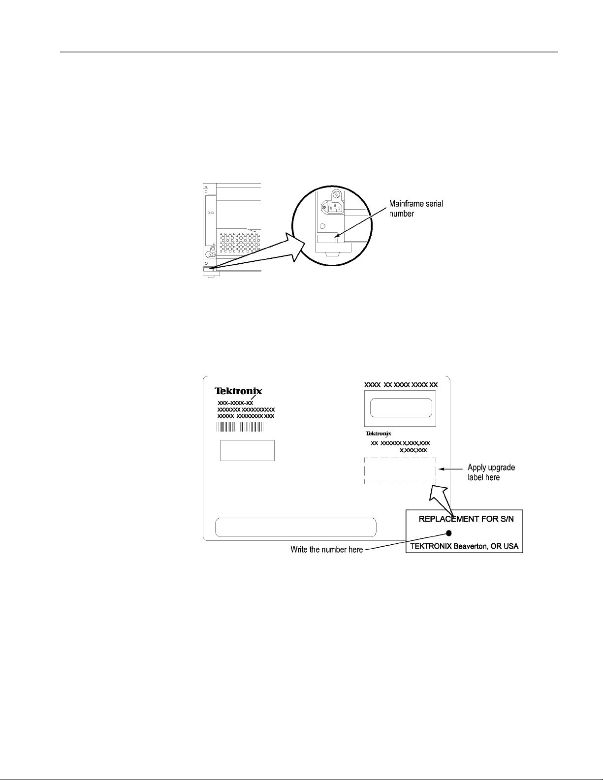
upgrading. It is located on a small white label below the power cord. (See
Figure 12.)
Figure 12: Mainframe serial number location
3. Write the mainframe serial number on the Replacement For Serial Number
label included in the kit. (See Figure 13.)
4. Affix the Replacement For Serial N umber Label to the large white label on
the side of the new TLA7016 Interface Module. (See Figure 13.)
talling the new TLA7016 Interface Module:
Figure 13: Adding the mainframe serial number to the Interface Module label
5. Plug the new TLA7016 Interface Module into the firstslot(slot0)ofthe
mainframe and tighten the two P1 mounting screws.
Set the Jumpers on the
Enhanced Mon itor Card
TLA7KUP Logic Analyzer Field Upgrade Kit 15
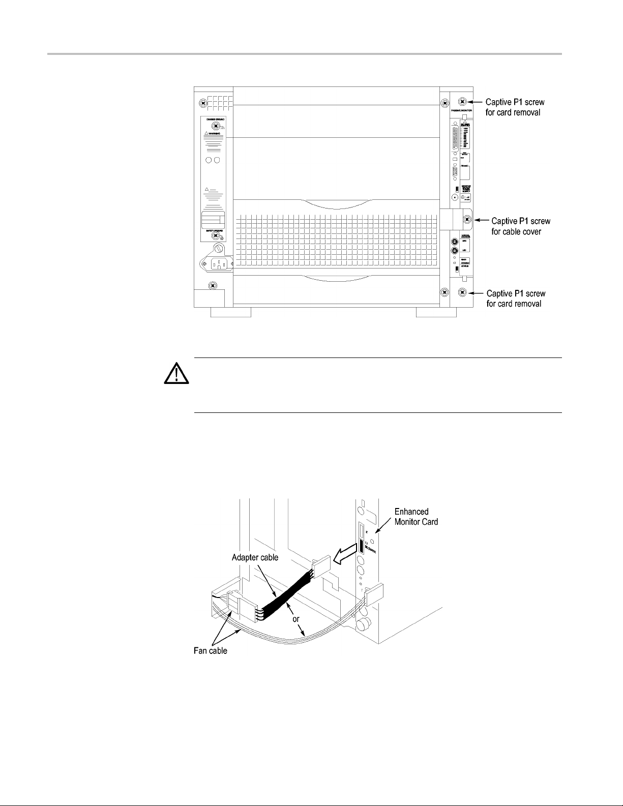
Thenextstepsaredoneatthebackoftheinstrument.
1. On the Enhanced Monitor Card, loosen the middle captive screw and remove
the cable cover near the middle of the card.
Page 30
TLA7KUP Option 19: TLA700 Series Benchtop Mainframe Upgrade
Figure 14: Remove the cable cover
CAUTION. Do not pull on the fan cable to disconnect the fan cable connector.
Pulling on the fan cable can damage the connector or the wires. To remove the
fan cab
before removing the fan cable.
2. Disco
le connector, disengage the locking connector on the fan cable connector
nnect the cable from the Enhanced Monitor Card. There may be a
3-inch adapter cable on the end of the fan cable. (See Figure 15.) The cable
configuration will be used to determine the proper jumper settings in step 5.
Figure 15: Check for an adapter cable and disconnect the cable
3. Loosen the top and bottom captive P1 screws.
16 TLA7KUP Logic Analyzer Field Upgrade Kit
Page 31
TLA7KUP Option 19: TLA700 Series Benchtop Mainframe Upgrade
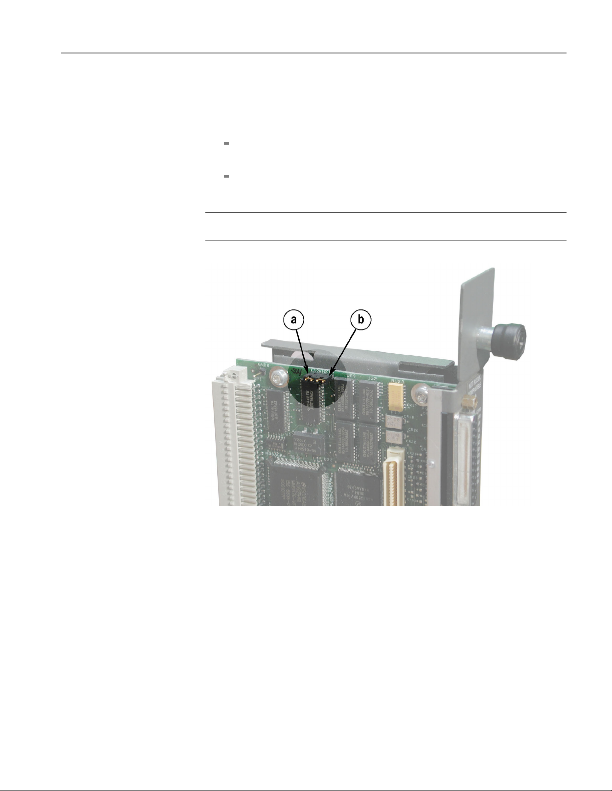
4. Pull the Enhanc
5. Note the pair of jumpers at the top of the Enhanced Monitor C ard. (See
Figure 16.)
If your fan has an adapter cable, remove the left jumper a and insert the
right jumpe
If your fan does not have an adapter cable, remove the right jumper b
and insert t
NOTE. Correct jumper configuration is important for the new firmware to
properly control the fan and to monitor the power supplies.
ed Monitor Card out of the mainframe.
r b.
he left jumper a.
Figure 16: Set the fan jumpers on the Enhanced Monitor Card
6. At the back of the Enhanced Monitor Card, connect a jumper on the bottom
two flash programming pins. (See Figure 17.)
7. If there are three pins above the flash programming pins, verify that there is
another jumper on the upper two pins.
TLA7KUP Logic Analyzer Field Upgrade Kit 17
Page 32

TLA7KUP Option 19: TLA700 Series Benchtop Mainframe Upgrade
Figure 17: Connect the flash jumper
8. Unless you need a static VXI address for the Enhanced Monitor Card, set
the arrows on the two white dials to F. This sets the card for VXI dynamic
addressing.
9. Plug the Enhanced Monitor Card firmly into the instrument, and tighten the
top and bottom P1 screws.
Set the Controller PC IP
Address Properties
10. Connect the fan cable (or cable adapter) to the connector labeled 1/BLOWER
on the Enhanced Monitor Card. (See Figure 17.)
11. Replace the fan cable cover and tighten the P1 screw.
Continue the installation by configuring the IP address of the controller PC:
1. Powe
NOTE. This upgrade kit requires TLA Application Software V5.6 running on the
controller PC. If you need to update your software, do so before continuing with
these procedures.
2. Click Start → Settings → C ontrol Panel → Network Connections.
3.R
NOTE. If you are using a PC for the controllerPC,itmayhaveseveralLANcards
installed. If so, more than one Local Area Connection will appear in the Network
Connections dialog box. You must choose which card you will use to communicate
with the mainframe, and then use the LAN connector on that card to connect to
the mainframe later in this procedure.
r on the controller PC.
ight-click the Local Area Connection of the LAN card you will use to
communicate with the mainframe (see note), and select Properties.
18 TLA7KUP Logic Analyzer Field Upgrade Kit
Page 33

TLA7KUP Option 19: TLA700 Series Benchtop Mainframe Upgrade
The Local Area C
onnection Properties dialog box appears. (See Figure 18.)
Figure 18: LAN Connection Properties dialog box
4. Scroll down the list and select Internet Protocol (TCP/IP).
5. Clic
TLA7KUP Logic Analyzer Field Upgrade Kit 19
k Properties. The IP Properties dialog box appears. (See Figure 19.)
Page 34

TLA7KUP Option 19: TLA700 Series Benchtop Mainframe Upgrade
te Firmware on the
Upda
Enhanced Mon itor Card
Figure 19: IP Properties dialog box
6. Check that the Obtain an IP address automatically radio button is selected. If
ot, select it.
it is n
7. Click OK and close the remaining Network Connection windows.
Continue the installation by installing three firmware files. In this procedure,
you first load the display firmware and check the mainframe display for proper
operation, and then load the remaining two files.
1. Connect the LAN cable (included with the kit) from the controller PC to the
LAN connector on the TLA7016 Interface Module in the mainframe.
2. Power on the TLA7016 mainframe. Note that no information appears in the
new display. This is normal operation while the flash jumper is installed on
he Enhanced Monitor Card.
t
3. Click Start → All Programs → Tektronix Logic Analyzer → TLA Firmware
Loader. The Firmware Loader Connection dialog box appears.
20 TLA7KUP Logic Analyzer Field Upgrade Kit
Page 35

TLA7KUP Option 19: TLA700 Series Benchtop Mainframe Upgrade
4. Click the binoc
(See Figure 20.)
ulars icon. The TLA Network Search dialog box appears.
Figure 20: TLA Network Search dialog box
5. Select Locate TLA systems in local subnet, a nd click Search.
6. When t
listed in the Connection window and click Connect. The Firmware Loader
dialog box appears. (See Figure 21 on page 22.)
NOTE. If your mainframe needs updated firmware, upgrade the mainframe
firmware before you upgrade the module firmware.
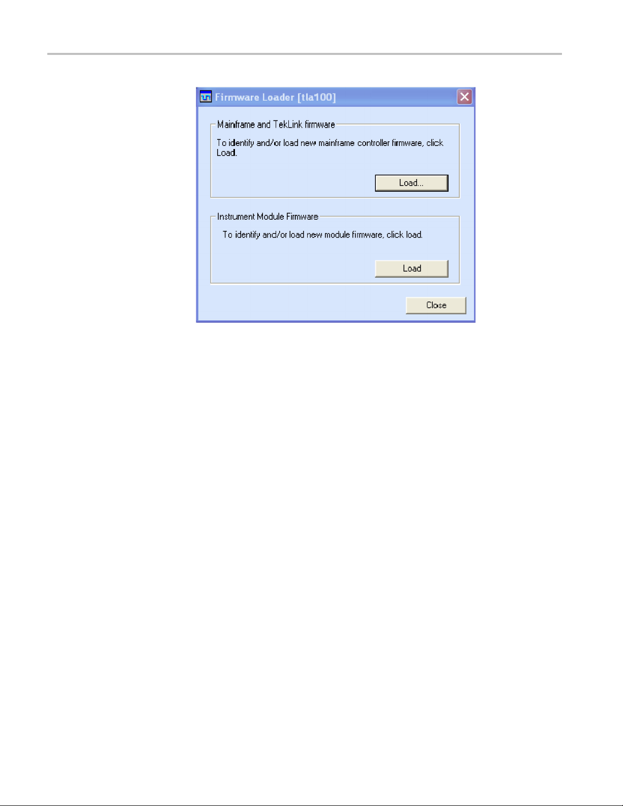
7. The Firmware Loader dialog box includes two Load buttons. Click the bottom
Load button (Instrument Module Firmware).
The firmware search progresses without indicating activity, and may take
about a minute to complete.
he network search is complete, click on the IP address of the TLA7016
TLA7KUP Logic Analyzer Field Upgrade Kit 21
Page 36

TLA7KUP Option 19: TLA700 Series Benchtop Mainframe Upgrade
Figure 21: Firmware Loader dialog box
8. When the search is finished, the Firmware Loader dialog box reappears with a
list of d
9. Click on the TLA BT Fan Ctl module displayed in the Devices Supported list
in the t
the firmware upgrade.
evices. (See Figure 22 on page 23.)
op portion of the window. This selects the Enhanced Monitor Card for
22 TLA7KUP Logic Analyzer Field Upgrade Kit
Page 37

TLA7KUP Option 19: TLA700 Series Benchtop Mainframe Upgrade
Figure 22: List of modules available for fi rmware update
10. From the Execute pull-down menu, select Load Firmware. A list of firmware
files displays.
11. Click TLA7016monitor.lod and click Open.
12. When prompted to confirm your action, click Yes.
13. The firmware flashing process begins and takes a bout a minute to finish.
When the process is done, click OK and exit the program.
14. Power off the mainframe.
15. Remove the lower flash jumper that you installed on the bottom two flash
programming pins of the Enhanced Monitor Card. Leave the upper jumper
connected.
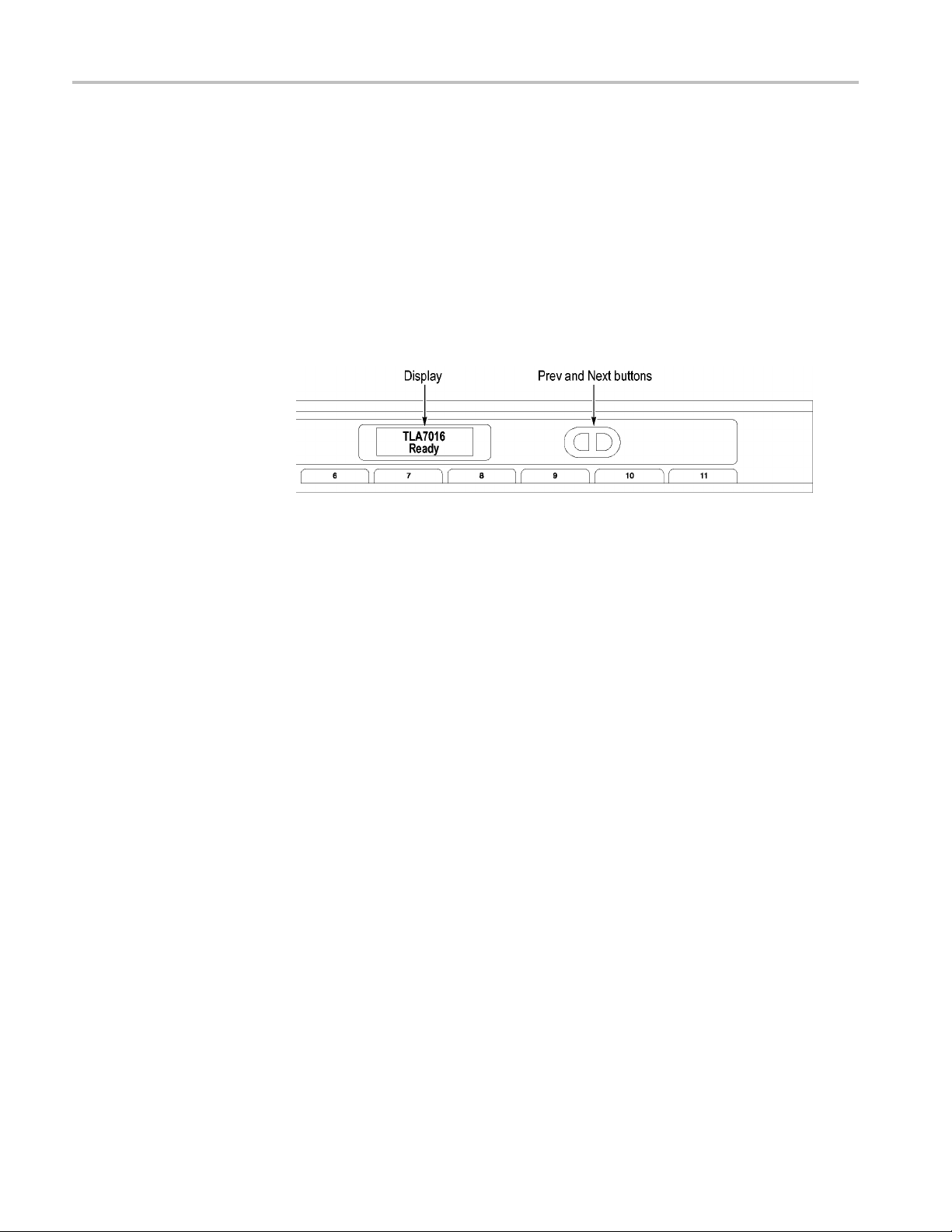
16. Check the mainframe display for proper operation.
Power on the mainframe. The mainframe initiates a self-test routine, and the
following message appears in the display:
TLA7016
Checking Mainframe
When the self-test passes
, the following message appears in the display:
TLA7016
TLA7KUP Logic Analyzer Field Upgrade Kit 23
Page 38
TLA7KUP Option 19: TLA700 Series Benchtop Mainframe Upgrade
Mainframe OK
If the following message appears flashing in the display,
WARN:Clean Filter
then make sure the rear fan air intake is clear of lint or other obstructions, and
then press both Prev and Next buttons simultaneously to clear the message.
After about a minute, the following message appears in the display:
TLA7016
Ready
Figure 23: New front panel display and control buttons
Complete the Firmware
Update
You can check mainframe status information by pressing the Prev or Next buttons
on the new front panel. Mainframe IP address, power s upply values, and chassis
temperature are some examples of the information available.
Load the remaining two firmware files:
1. Click Start → All Programs → Tektronix Logic Analyzer → TLA Firmware
Loader.
2. Select your instrument from the Firmware Loader - Connection dialog box
and click Connect.
3. Click Load in the upper portion of the Load Firmware dialog box. The
Mainframe Firmware dialog box opens. (See Figure 24.)
24 TLA7KUP Logic Analyzer Field Upgrade Kit
Page 39

TLA7KUP Option 19: TLA700 Series Benchtop Mainframe Upgrade
Figure 24: Mainframe Firmware dialog box
Attach the Upgrade Kit
Label to the Instrument
NOTE. Yo
4. Select the TLA7016 firmware and then click Update Firmware.
5. Follow the on-screen instructions.
6. When the process is done, click OK, and exit the program.
7. Power off the mainframe.
8. Power on the mainframe.
9. Repe
10. Select the TekLink firmware and then click Update Firmware.
11. Repeat steps 5 through 8 for the TekLink firmware.
12. Start the TLA Application and verify that the TLA7016 mainframe appears
After completing the previous steps, you need to install the upgrade kit label on
the instrument to indicate that the kit is installed.
1. Select the correct instrument upgrade label from the sheet of labels, and affix
u must load the firmware files in the order listed below.
at steps 1 through 3.
in the TLA Connection dialog box.
it to the lower front panel of the instrument. (See Figure 43.)
TLA7KUP Logic Analyzer Field Upgrade Kit 25
Page 40

TLA7KUP Option 19: TLA700 Series Benchtop Mainframe Upgrade
Figure 25: Front panel upgrade label location
Connect t
he Instrument
Through TekLink
Preset IP Addresses
TekLink is a mainframe real-time communication system that coordinates trigger
signals, input/output signals, and time references between mainframes.
TekLink uses a 2-meter cable (included with this kit) to connect between two
TLA7000 Series logic analyzers. If you want to connect more than three benchtop
mainframes together, you need a TekLink TL708EX Hub and more TekLink
.
cables
For more information on connecting TekLink components, refer to the TLA7000
Series Logic Analyzer Installation Manual.
You may need to change the IP address of the benchtop mainframe, depending
on the requirements of the network that it will be connected to. A preset list of
recommended IP addresses is programmed into the TLA7016 Interface Module.
For information about entering other IP addresses, refer to the TLA7000 Series
Logic Analyzer Installation Manual.
To cycle through the list of preset IP addresses, do the following:
1. Press and hold the recessed RESET button on the TLA7016 Interface Module.
(See Figure 26.) The front-panel display cycles every 2-3 seconds to the
next preset IP address (See Table 4.).
26 TLA7KUP Logic Analyzer Field Upgrade Kit
Page 41

Figure 26: Setting the IP address
Table 4: Preset IP addresses
Selection IP address S ubnet m ask
Use: DHCP
Use:
169.254.0.19
Use:
169.254.0.20
Use:
8.0.19
192.16
Use:
192.168.0.20
Factory
default
No change
–––
169.254.
169.254.0.20 255.255.0.0 0.0.0.0
192.168.0.19 255.255.0.0 0.0.0.0
192.16
–––
–––
0.19
8.0.20
255.255.
255.25
0.0
5.0.0
TLA7KUP Option 19: TLA700 Series Benchtop Mainframe Upgrade
Default
gateway Comments
IP addressing provided by DHCP-capable router
0.0.0.0
0.0.0.
0
Static, non-routable address used for direct PC
connection
Static, non-routable address used for direct PC
ion
connect
, non-routable address used for private LAN with
Static
DHCP-capable router
Static, non-routable address used for private LAN with
DHCP-capable router
Return to factory settings (Use DHCP and restore
ult Host Name to TLA7016_<Mainframe S/N>)
defa
Retain current IP address and Host Name
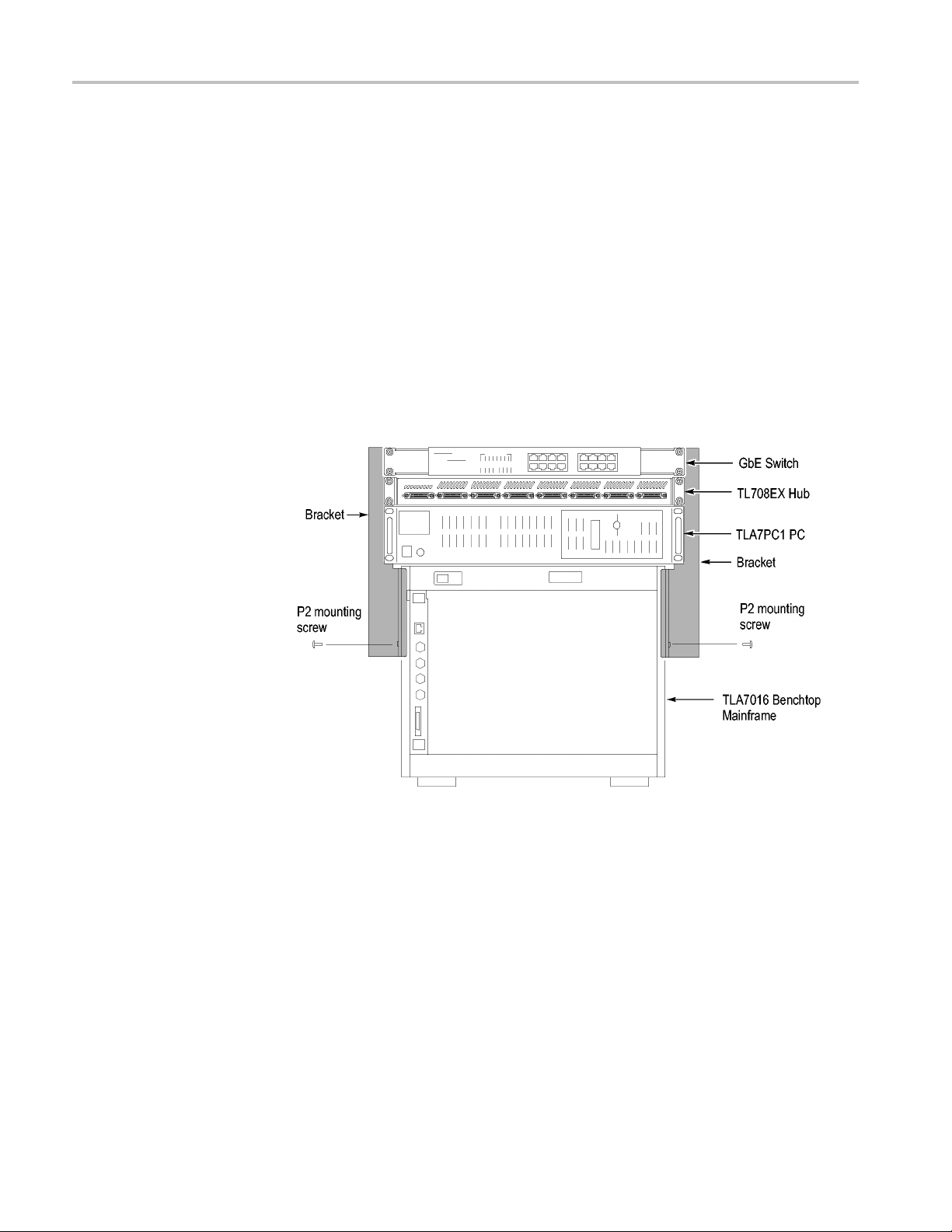
Installing the Bracket Kit
ou are using your benchtop logic analyzer outside of a rackmount e nvironment,
If y
you can use the bracket kit to mount the TLA7PC1 controller, GbE switch, and
TL708EX Hub together with your benchtop mainframe.
Left and right-side brackets and mounting screws are included in the kit. (See
Figure 27.) Use the following procedure.
TLA7KUP Logic Analyzer Field Upgrade Kit 27
Page 42
TLA7KUP Option 19: TLA700 Series Benchtop Mainframe Upgrade
1. Place the compo
the heaviest units lowest in the stack.
2. Align one of th
reaches all of the components, but does not extend above the top unit.
3. Fasten the b
screws preinstalled on the bracket.
4. Repeat step
5. If necessary, relocate the instrument brackets on the components you are
mounting.
the back of the unit, with installation instructions on the bottom of the unit.
6. Using the
components to the brackets.
nents you want to mount on top of the logic analyzer, putting
e brackets to the frame of the logic analyzer so that the bracket
racket to the logic analyzer with one of the 8-32, P2 Pozidriv
s 2 and 3 for the bracket on the other side of the logic analyzer.
For example, the brackets on the TL708EX Hub come mounted to
10-32, P2 Pozidriv screws preinstalled on the brackets, fasten the
Figure 27: Bracket kit for the TLA7016 benchtop mainframe installed
28 TLA7KUP Logic Analyzer Field Upgrade Kit
Page 43

TLA7KUP Option 19: TLA700 Series Benchtop Mainframe Upgrade
Troubleshooting Tips
If you cannot es
mainframe, do the following:
1. BringuptheDO
The address that returns should be 169.254.x.x with a subnet mask of
255.255.0.
2. If the above address is not returned, enter ipconfig release and then ipconfig
renew.
3. Enter ping 169.254.0.19 (the factory-set IP address of the mainframe). See
the follow
tablish a communication link between the controller and the
S window on the controller and enter ipconfig.
0 (the default IP address of the controller).
ing figure for an example of the expected reply from the mainframe.
Figure 28: Seeking a reply from the mainframe
4. If you get a reply using the ping command, but cannot see the mainframe in
configuration dialog box, check to see if a firewall is enabled.
the
Attach the Upgrade Kit
Label to the Instrument
TLA7KUP Logic Analyzer Field Upgrade Kit 29
After completing all of the previous steps, you need to install the upgrade kit label
on the instrument to indicate that the kit is installed. Locate the big label on the
de of the TLA7016 Interface Module and attach the TLA7KUP kit label as
si
shown. (See Figure 45.)
NOTE. If there already is an upgrade kit label installed, install the new label just
above or below the old one.
Page 44

TLA7KUP Option 19: TLA700 Series Benchtop Mainframe Upgrade
Figure 29:
Kit label locations
30 TLA7KUP Logic Analyzer Field Upgrade Kit
Page 45

TLA7KUP Option 21: Power Supply Upgrade
TLA7KUP Option 21 provides parts and instructions to upgrade your TLA7016
Benchtop Mainframe Logic Analyzer by replacing the power supply with a new
higher-capa
Instruments
Instruments Serial number range
TLA7016 Logic Analyzers
TLA7016 Logic Analyzers
Minimum Tool and Equipment List
3/32 hex driver, Phillips P1 screwdriver.
Parts List
city power supply.
Serial numbers B019999 and below
Upgraded from TLA700 series (with
TLA7KUP Option 19)
Installation Prerequisite
Table 5: TLA7KUP Option 21 parts list
Quantity Part number Description
1 ea 650-5105-00 Power supply assembly with label
1ea
2 ea 131-4356-xx Jumper with pull-tab
2 ea 131-3199-xx
1 ea 335-1863-xx
1 ea 334-9921-xx TLA7016 rear-panel label
Requires TLA Application Software V5.6, Windows XP, and 512 MB m inimum
mainframe memory.
NOTE. If you have a TLA720, TLA721, or TLA7XM mainframe, you must upgrade
it to a TLA7016 Benchtop Mainframe with TLA7KUP Option 19 before continuing
with this procedure. Contact your local Tektronix representative for upgrade
information.
N/A
TLA7KUP kit label
Low profile jumpers
TLA7016 Upgraded with TLA7KUP Option 21 front
panel label
TLA7KUP Logic Analyzer Field Upgrade Kit 31
Page 46
TLA7KUP Option 21: Power Supply Upgrade
Installation Instructions
Refer to the illustrations as you perform the following procedures.
CAUTION. To prevent static discharge damage, service the product only
in a static-free environment. Observe standard handling precautions for
static-sensitive devices while installing this kit. Always wear a grounded wrist
strap, grou
nded foot strap, and static resistant apparel while installing this kit.
Remove the Blower
Assembly
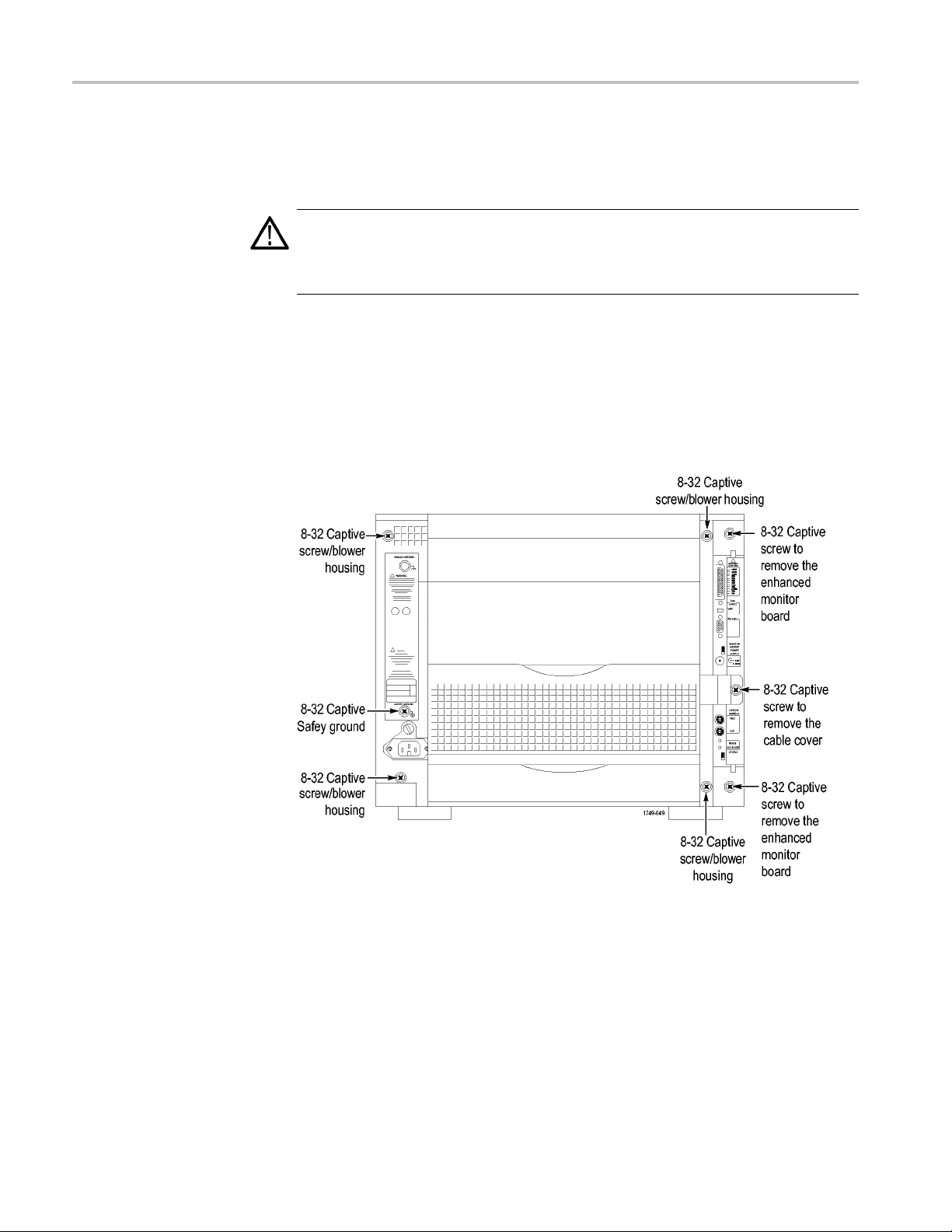
Begin by removing the blower assembly. (See Figure 30.) To remove the blower
assembly
1. Disconnect all cords, probes, and modules from the instrument.
2. From the back of the chassis, loosen the captive screw attaching the blower
, perform the following steps:
cable cover, and then remove the cover.
Figure 30: Location of blower assembly screws
3. Unplug the blower cable.
4. From the back of the chassis, loosen the four captive screws attaching the
blower assembly to the instrument, and loosen the safety ground captive screw.
5. Remove the blower assembly and set it aside on a clean working surface.
32 TLA7KUP Logic Analyzer Field Upgrade Kit
Page 47

TLA7KUP Option 21: Power Supply Upgrade
Figure 31: Remove the blower assembly
TLA7KUP Logic Analyzer Field Upgrade Kit 33
Page 48

TLA7KUP Option 21: Power Supply Upgrade
Remove the Old Power
Supply
After you have r
the mainframe by completing the following steps:
1. Using the hand
therearofthemainframe.
emoved the blower assembly, remove the old power supply from
le on the power supply, firmly pull out the power supply from
Figure 32: Remove the power supply
2. Remove the two 3/32 hex drive screws and washers to remove the handle
from the power supply.
34 TLA7KUP Logic Analyzer Field Upgrade Kit
Page 49
TLA7KUP Option 21: Power Supply Upgrade
Install the New Power
Supply
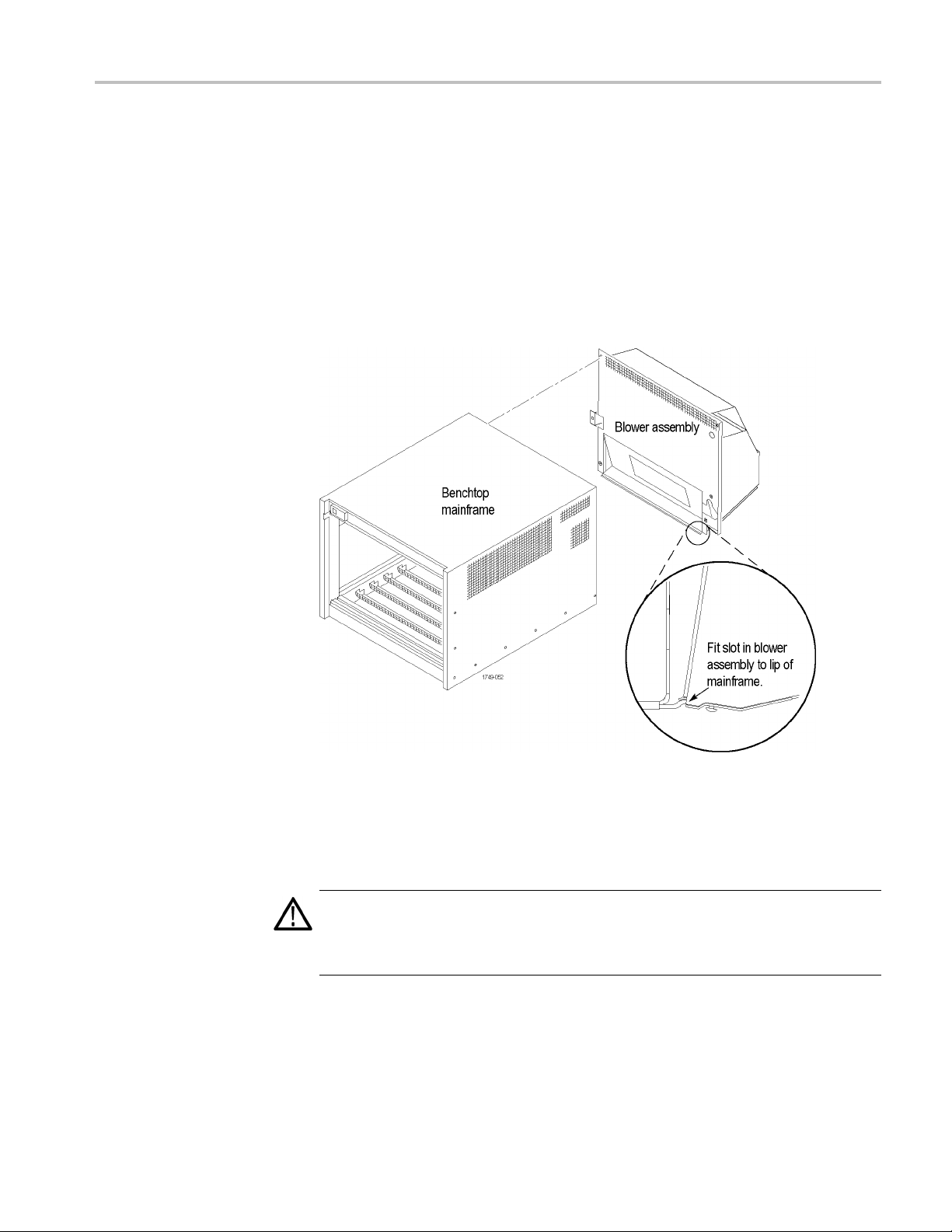
Complete the fo
1. Reinstall the power supply handle.
2. Slide the power supply into the mainframe.
3. Push the power supply handle in firmly to ensure that the connectors are
completely seated into the back plane connectors.
4. Reinstall the blower assembly, making sure that the slot at the bottom of the
blower assembly fits to the lip on the mainframe, and the fan cable protrudes
through the fan cable opening in the blower assembly shroud.
llowing steps to reinstall the power supply in the mainframe:
Figure 33: Reinstall the blower assembly
Set the Jumpers on the
Enhanced Mon itor Card
CAUTION. Do not pull on the fan cable to disconnect the fan cable connector.
Pulling on the fan cable can damage the connector or the wires. To remove the
fan cable connector, disengage the locking connector on the fan cable connector
before removing the fan cable.
1. Note whether there is a 3-inch adapter cable on the end of the fan cable. (See
Figure 34.) The cable configuration will be used to determine the proper
jumper settings in step 4.
TLA7KUP Logic Analyzer Field Upgrade Kit 35
Page 50

TLA7KUP Option 21: Power Supply Upgrade
Figure 34: Disconnect the fan cable
2. Loosen the top and bottom captive screws.
3. Pull the Enhanced Monitor Card out of the mainframe.
Figure 35: Remove the Enhanced Monitor Card
36 TLA7KUP Logic Analyzer Field Upgrade Kit
Page 51

TLA7KUP Option 21: Power Supply Upgrade
4. Note the pair of
Figure 36.) Also note the circuit board number label near the bottom of the
Enhanced Monitor Card.
If your fan has an adapter cable, insert both jumpers a and b.
If your fan d
starts with 679-3982, remove both jumpers a and b.
If the circu
cable. Insert both jumpers a and b.
NOTE. Correct jumper configuration is important for the new firmware to
properly control the fan and to monitor the power supplies.
jumpers at the top of the Enhanced Monitor Card. (See
oes not have an adapter cable and the circuit board number
it board number is 679-6146, there should not be an adaptor
Figure 36: Set the jumpers on the Enhanced Monitor Card
5. At the back of the Enhanced Monitor Card, connect a jumper (with a pull-tab)
the bottom two flash programming pins. (See Figure 37.)
on
6. If there are three pins above the flash programming pins, verify that there is
nother jumper on the upper two pins.
a
TLA7KUP Logic Analyzer Field Upgrade Kit 37
Page 52

TLA7KUP Option 21: Power Supply Upgrade
Update the Enhanced
tor Card Firmware
Moni
Figure 37:
7. Unless yo
8. Plug the Enhanced Monitor Card firmly into the instrument, and tighten the
9. Reconnect the fan cable (or cable adapter) to the connector labeled
10. Replace the fan cable cover a nd tighten the captive screw.
Complete the following steps to update the monitor firmware and to check the
main
NOTE. If your mainframe needs updated firmware, upgrade the mainframe
firmware before you upgrade the module firmware.
1. If you have not already done so, connect the LAN cable from the controller PC
Connect the flash jumper
u need a static VXI address for the Enhanced Monitor Card, set
the arrows on the two white dials to F. This sets the card for VXI dynamic
addressing.
top and bottom captive screws.
1/BLOWER on the Enhanced Monitor Card. (See Figure 37.)
frame for proper operation.
to the LAN connector on the TLA7016 Interface Module in the mainframe.
2. Power on the TLA7016 mainframe. Note that no information appears in the
display. This is normal operation while the flashjumperisinstalledonthe
Enhanced Monitor Card.
3. Click Start → All Programs → Tektronix Logic Analyzer → TLA Firmware
Loader. The Firmware Loader Connection dialog box appears.
4. Click the binoculars icon. The TLA Network Search dialog box appears.
(See Figure 38.)
38 TLA7KUP Logic Analyzer Field Upgrade Kit
Page 53

TLA7KUP Option 21: Power Supply Upgrade
Figure 3
5. Select L
6. When the network search is complete, click o n the IP address of the TLA7016
7. The Fi
8: TLA Network Search dialog box
ocate TLA systems in local subnet, and c lick Search.
in the Connection window and click Connect. The Firmware Loader
listed
dialog box appears. (See Figure 39 on page 40.)
rmware Loader dialog box includes two Load buttons. Click the bottom
Load button (Instrument Module Firmware).
rmware search progresses without indicating activity, and may take
The fi
about a minute to complete.
TLA7KUP Logic Analyzer Field Upgrade Kit 39
Page 54
TLA7KUP Option 21: Power Supply Upgrade
Figure 39: Firmware Loader dialog box
8. When the search is finished, the Firmware Loader dialog box reappears with a
list of d
9. Click on the TLA BT Fan Ctl module displayed in the Devices Supported list
in the t
the firmware upgrade.
evices. (See Figure 40 on page 41.)
op portion of the window. This selects the Enhanced Monitor Card for
40 TLA7KUP Logic Analyzer Field Upgrade Kit
Page 55

TLA7KUP Option 21: Power Supply Upgrade
Figure 40: List of modules available for fi rmware update
10. From the Execute pull-down menu, select Load Firmware. A list of firmware
files displays.
11. Click TLA7016monitor.lod and click Open.
12. When prompted to confirm your action, click Yes.
13. The firmware flashing process begins and takes a bout a minute to finish.
When the process is done, click OK and exit the program.
14. Power off the mainframe.
15. Remove the lower flash jumper that you installed on the bottom two flash
programming pins of the Enhanced Monitor Card. Leave the upper jumper
connected.
16. Check the mainframe display for proper operation.
Power on the mainframe. The mainframe initiates a self-test routine, and the
following message appears in the display:
TLA7016
Checking Mainframe
When the self-test passes
, the following message appears in the display:
TLA7016
TLA7KUP Logic Analyzer Field Upgrade Kit 41
Page 56

TLA7KUP Option 21: Power Supply Upgrade
Mainframe OK
If the following message appears flashing in the display,
WARN:Clean Filter
then make sure the rear fan air intake is clear of lint or other obstructions, and
then press both Prev and Next buttons simultaneously to clear the message.
After about a minute, the following message appears in the display:
TLA7016
Ready
Figure 41: Front panel display and control buttons
Attach the Upgrade Kit
Labels to the Instrument
You can check mainframe status information by pressing the Prev or Next buttons
on the new front panel. Mainframe IP address, power s upply values, and chassis
temperature are some examples of the information available.
After completing the previous steps, you need to install the upgrade kit labels on
the instrument to indicate that the kit is installed.
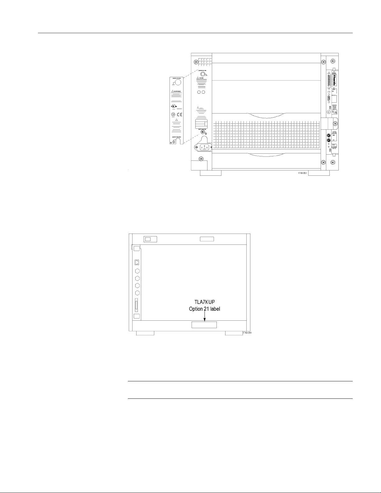
1. Locate the new power label and attach it to the rear of the instrument over the
old label. (See Figure 42.)
42 TLA7KUP Logic Analyzer Field Upgrade Kit
Page 57
TLA7KUP Option 21: Power Supply Upgrade
Figure 42: Power label location
2. Locate the instrument upgrade label (“Upgraded with TLA7KUP Option
21”) and affix it to the lower front panel of the instrument as shown. (See
Figure 43.) If there already is another label on the front panel, place the new
label next to the old label.
Figure 43: Front panel upgrade label location
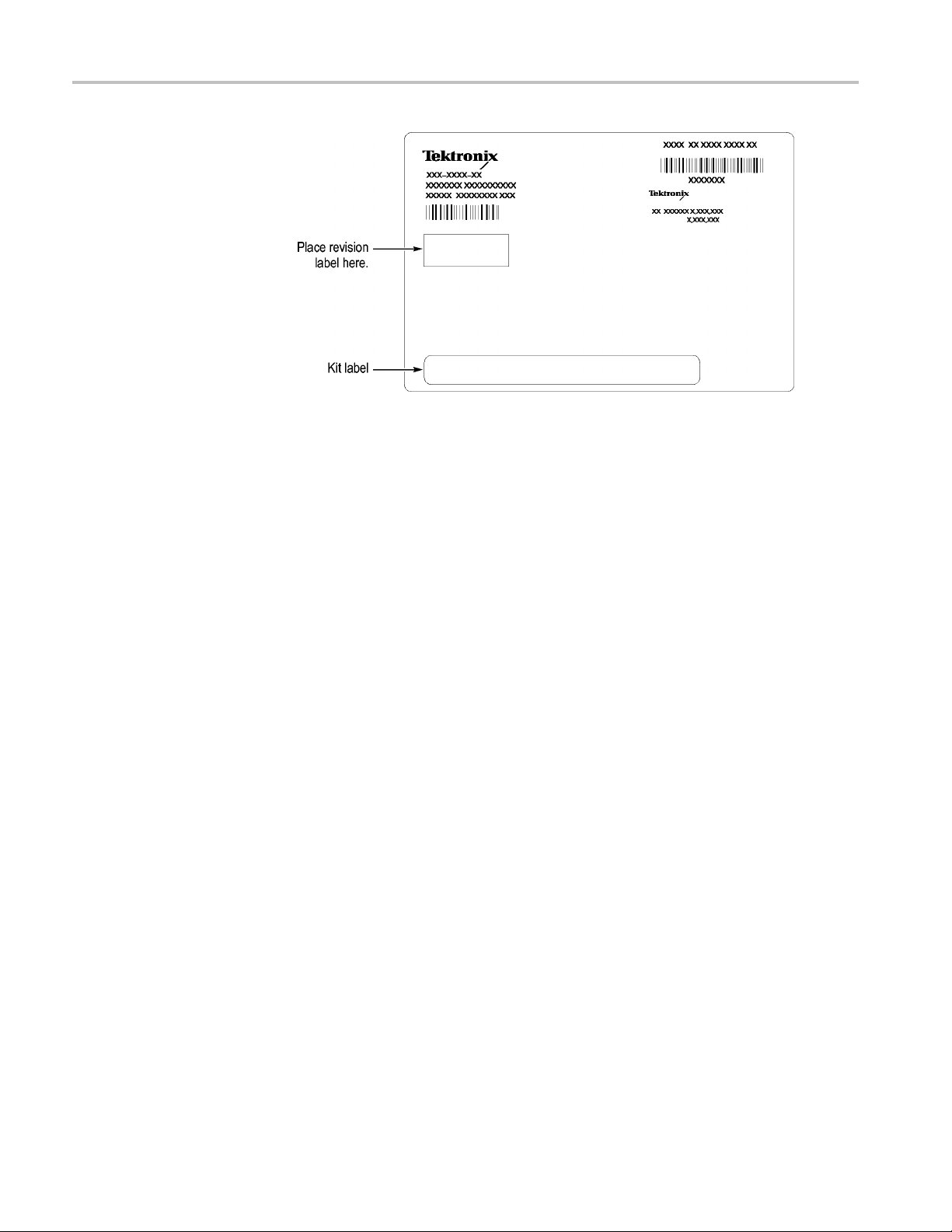
3. Locate the big label on the side of the TLA7016 Interface Module and attach
the TLA7KUP kit label as shown. (See Figure 45.)
NOTE. If there already is an upgrade kit label installed, install the new label just
bove or below the old one.
a
TLA7KUP Logic Analyzer Field Upgrade Kit 43
Page 58
TLA7KUP Option 21: Power Supply Upgrade
Figure 44:
Kit label locations
44 TLA7KUP Logic Analyzer Field Upgrade Kit
Page 59

TLA7KUP Option 29: Floppy Disk Drive
TLA7KUP Option 29 provides parts and instructions to add an USB floppy disk
drive to your TLA7000 series logic analyzer.
Instruments
Instruments Serial number range
TLA7012 Series Logic Analyzers
TLA7PC1 Benchtop Controllers
All serial n
All serial
umbers
numbers
Minimum T
Parts Li
ool and Equipment List
st
Installation Prerequisite
Installation Instructions
No special tools or equipment are required.
Table 6: TLA7KUP Option 29 parts list
ty
Quanti
1 ea 119-6960-xx
1ea
Requires TLA Application Software V5.0 or higher, Windows XP, and 512 MB
minimum mainframe memory.
Follow the instructions that come with the floppy disk drive. Connect the floppy
disk drive to one of the unused USB ports on the logic analyzer or external
controller.
Part nu
N/A
mber
ption
Descri
floppy disk drive, USB
3.5 in
TLA7KUP kit label
ttach the Upgrade Kit
A
Label to the Instrument
TLA7KUP Logic Analyzer Field Upgrade Kit 45
After completing the previous steps, you need to install the upgrade kit label on
the instrument to indicate that the kit is installed.
Locate the big label on the bottom of the portable mainframe or on the side of
the TLA7016 Interface Module and attach the TLA7KUP kit label as shown.
(See Figure 45.)
Page 60

TLA7KUP Option 29: Floppy Disk Drive
NOTE. If there a
above or below the old one.
Figure 45: Kit label locations
lready is an upgrade kit label installed, install the new label just
46 TLA7KUP Logic Analyzer Field Upgrade Kit
Page 61

TLA7KUP Option 39: USB Security Block for TLA7012
Series Logic Analyzers
TLA7KUP Option 39 provides parts and instructions to add a USB Security block
to your TLA7012 Logic Analyzer.
Instruments
Instruments Serial number range
TLA7012 Series Logic Analyzers
Minimum Tool and Equipment List
T-15 TOR X dr i ve r
All serial numbers
Parts Lis
t
Installation Prerequisite
Installation Instructions
Table 7: TLA7KUP Option 39 parts list
y
Quantit
1 ea 407-5154-00
1 ea 407-5155-00
2 ea 211-0721-00
1 ea 335-1469-00
1ea
None
This procedure contains three parts:
Disconnect the USB cables from inside the front of the instrument (you must
remove the front panel display assembly to gain access).
Part num
N/A
ber
Descrip
USB Sec
USB Sec
Brack
Set of
TLA7KUP Kit labels
tion
urity block, bracket, lock housing, main
urity block, bracket, lock housing, cover
et screw (one spare included)
USB Security block labels
Mount the lock assembly over the USB connectors on the rear of the
instrument.
Apply labels.
TLA7KUP Logic Analyzer Field Upgrade Kit 47
Page 62

TLA7KUP Option 39: USB Security Block for TLA7012 Series Logic Analyzers
CAUTION. To prevent static discharge damage, service the product only
in a static-fr
static-sensitive devices while installing this kit. Always wear a grounded wrist
strap, grounded foot strap, and static resistant apparel while installing this kit.
ee environment. Observe standard handling precautions for
Disable the Front-Panel
USB Connections
Start the installation by doing the following steps. (See Figure 46.)
1. Disconnec
2. Set the instrument on the bottom feet.
3. Remove the six T-15 screws from the right cover and remove the cover.
t all cords, probes, and modules from the instrument.
48 TLA7KUP Logic Analyzer Field Upgrade Kit
Page 63

TLA7KUP Option 39: USB Security Block for TLA7012 Series Logic Analyzers
Figure 46: Remove the instrument enclosure
4. Remove the accessory pouch and snap studs (4 T-15 screws).
5. Remove the four skid feet from the left side (4 T-15 screws).
6. Re
7.S
TLA7KUP Logic Analyzer Field Upgrade Kit 49
move the three remaining T-15 screws from the top left cover and then
remove the cover.
et the instrument on the rear feet.
Page 64

TLA7KUP Option 39: USB Security Block for TLA7012 Series Logic Analyzers
8. Remove the 12 T-
Figure 47: Remove the front-panel trim screws
9. Set the instrument back on the bottom feet.
10. Tilt the top of the front panel trim out about 8 inches. (See Figure 48.)
15 screws from the front panel trim. (See Figure 47.)
gure 48: Tilt the front panel forward for cable access
Fi
sconnect the three USB cables from the front panel assembly. (See
11.Di
Figure 49.)
50 TLA7KUP Logic Analyzer Field Upgrade Kit
Page 65

TLA7KUP Option 39: USB Security Block for TLA7012 Series Logic Analyzers
Figure 49: Disconnect the USB cables from the front panel
12. Reinstall the front panel assembly by following steps 1 through 11 in reverse.
To avoid damaging the USB and DVD cables, dress the cables properly just
before you attach the front panel to the chassis. (See Figure 50.)
Figure 50: Dress the cables properly
Attach Rear-Panel USB
Security Block
TLA7KUP Logic Analyzer Field Upgrade Kit 51
Continue the installation with the following procedure:
1. Set the instrument on the bottom feet with the rear panel facing you.
sert the tab of the main lock housing into the slot on the instrument under
2. In
the USB connectors. Fasten the lock housing to the instrument with the T-15
screw. (See Figure 51.)
Page 66

TLA7KUP Option 39: USB Security Block for TLA7012 Series Logic Analyzers
Figure 51: Mount the main lock housing to the instrument
3. Connect the cables. Do not use the top port. (See Figure 52.)
Figure 52: Connect the cables
4. Slide the lock housing cover into the main lock housing and over the cables
so that the padlock holes line up. (See Figure 53.)
52 TLA7KUP Logic Analyzer Field Upgrade Kit
Page 67

TLA7KUP Option 39: USB Security Block for TLA7012 Series Logic Analyzers
Figure 53: Slide the housing cover into place
5. Attach a padlock through the padlock holes. The holes will accommodate
a9/32-i
Figure 54: Attach a padlock
n shackle. (See Figure 54.)
Attach the Upgrade Kit
Labels to the Instrument
TLA7KUP Logic Analyzer Field Upgrade Kit 53
After completing the previous steps, you need to install the upgrade kit labels on
the instrument to indicate that the kit is installed.
1. Locate the big label on the bottom of the instrument, and then attach the
TLA7KUP kit label. (See Figure 55.)
Page 68
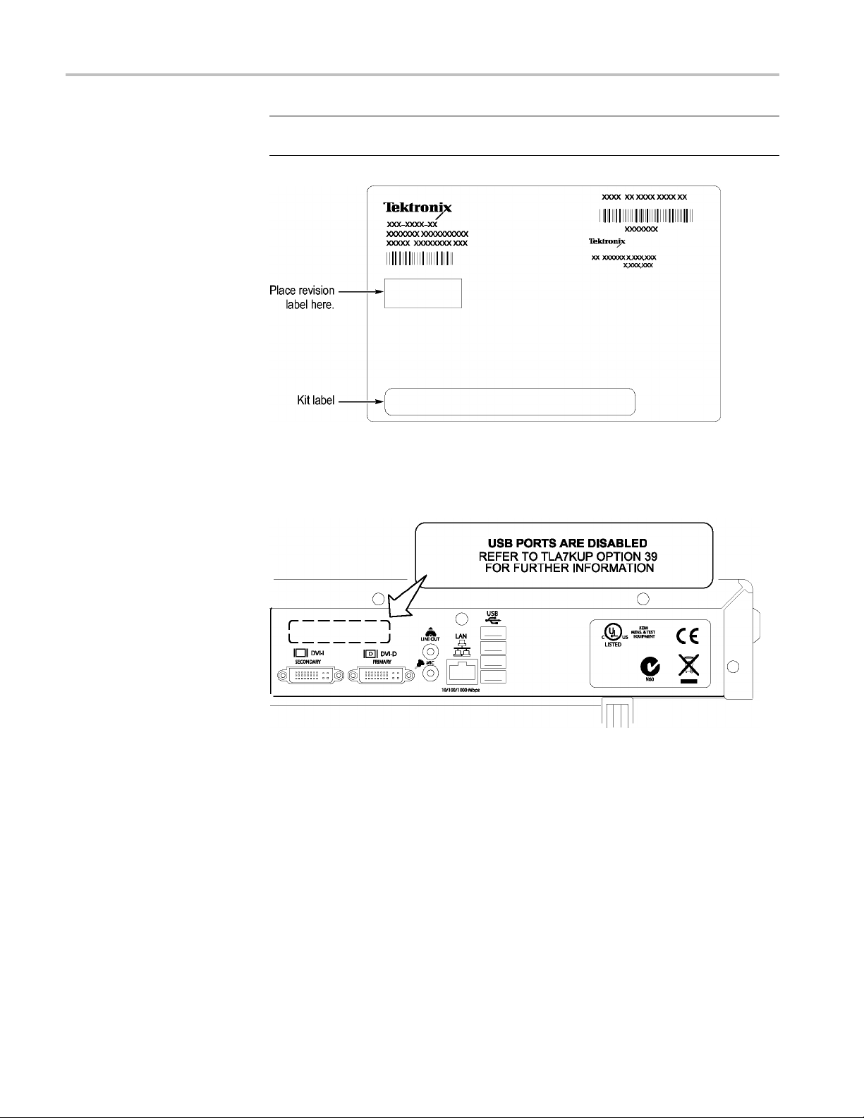
TLA7KUP Option 39: USB Security Block for TLA7012 Series Logic Analyzers
NOTE. If there a
above or below the old one.
Figure 55: Attach the revision and kit labels
2. Attach one of the USB PORTS ARE DISABLED notification labels on the
top rear of the instrument. (See Figure 56.)
lready is an upgrade kit label installed, install the new label just
re 56: Attach the notification label to the rear of the instrument
Figu
3. Att
54 TLA7KUP Logic Analyzer Field Upgrade Kit
ach another USB PORTS ARE DISABLED notification label on the front
of the instrument, over the USB connectors. (See Figure 57.)
Page 69

TLA7KUP Option 39: USB Security Block for TLA7012 Series Logic Analyzers
Figure 57: Attach the notification label over the front-panel USB connectors
TLA7KUP Logic Analyzer Field Upgrade Kit 55
Page 70

TLA7KUP Option 39: USB Security Block for TLA7012 Series Logic Analyzers
56 TLA7KUP Logic Analyzer Field Upgrade Kit
Page 71

TLA7KUP Option 46: TLA Application Software Upgrade
TLA7KUP Option 46 supports the upgrade to TLA Application Software V5.6.
This kit provides instructions to upgrade the TLA application software and
firmware for a
V5.0 or higher. This software will run only on instruments with Windows XP
purchased from Tektronix. The software will also run on a PC with Windows XP.
Instruments
Instruments Serial number range
TLA7000 Series Logic Analyzers
Installation Prerequisite
Requires TLA Application Software V5.0 (or higher), Windows XP.
Parts List
TLA7000 Series logic analyzer with TLA Application S oftware
All serial numbers
Table 8: TLA7KUP Option 46 parts list
Quantity Part number Description
1ea
1ea
1 sheet
5ea
1ea
Minimum Tool and Equipment List
No special tools or equipment are required to install this option.
Upgrade Instruction Overview
NOTE. Third-party software applications are included to use with your logic
analyzer. These applications may include software license agreements. Be sure
to abide by those license agreements.
N/A Tektronix Logic Analyzer Family Application Software
V5.6
N/A Nero software CD
N/A Software revision labels
131-4356-xx Jumper with pull-tab
N/A
TLA7KUP kit label
TLA7KUP Logic Analyzer Field Upgrade Kit 57
Page 72

TLA7KUP Option 46: TLA Application Software Upgrade
While performi
Throughout this procedure you will see the term "log on as Administrator."
The instrumen
password) so you may not see the log on prompt. If the network setups have
been changed on your instrument, make sure that you log on as Administrator
or as a user who has administrator privileges. Failure to do so can prevent the
software upgrade from completing successfully.
After logging on as administrator, quit any applications.
If your instrument does not display the file extensions, you need to change
your folder options to display the file extensions. (From the Control Panel,
double-click Folder Options, select the View tab, and then deselect the "Hide
file extensions for known file types" selection.)
Use the Microsoft Windows Add or Remove Programs Control Panel utility
to remove existing software.
You may be asked to restart the instrument after you install each software
package. If you do not restart the instrument when prompted, your software
may no
If the instrument does not restart normally, press and hold the On/Standby
butto
ng the upgrade procedures, keep the following items in mind:
t is set up to automatically log on as Administrator (with no
t install properly and can cause unpredictable behavior.
nforfive or six seconds to force a shutdown.
Update the Software
NOTE. You may want to compare the software version listed under Software
Compatibility in the release notes against the software on your instrument. If the
software versions do not match, remove the old software using the Microsoft
ndows Add or Remove Programs utility and then install the new software from
Wi
the TLA Application CD.
hen you reinstall the CheckIt Utilities software, you will be prompted for a
W
serial number; use U7-999999.
ollow the instructions to install the NI-GPIB software to use with iView. (See
F
page 65, Install the NI-GPIB Software.)
The TLA Application software uses a wizard to remove older software and install
the new software for your instrument.
58 TLA7KUP Logic Analyzer Field Upgrade Kit
Page 73
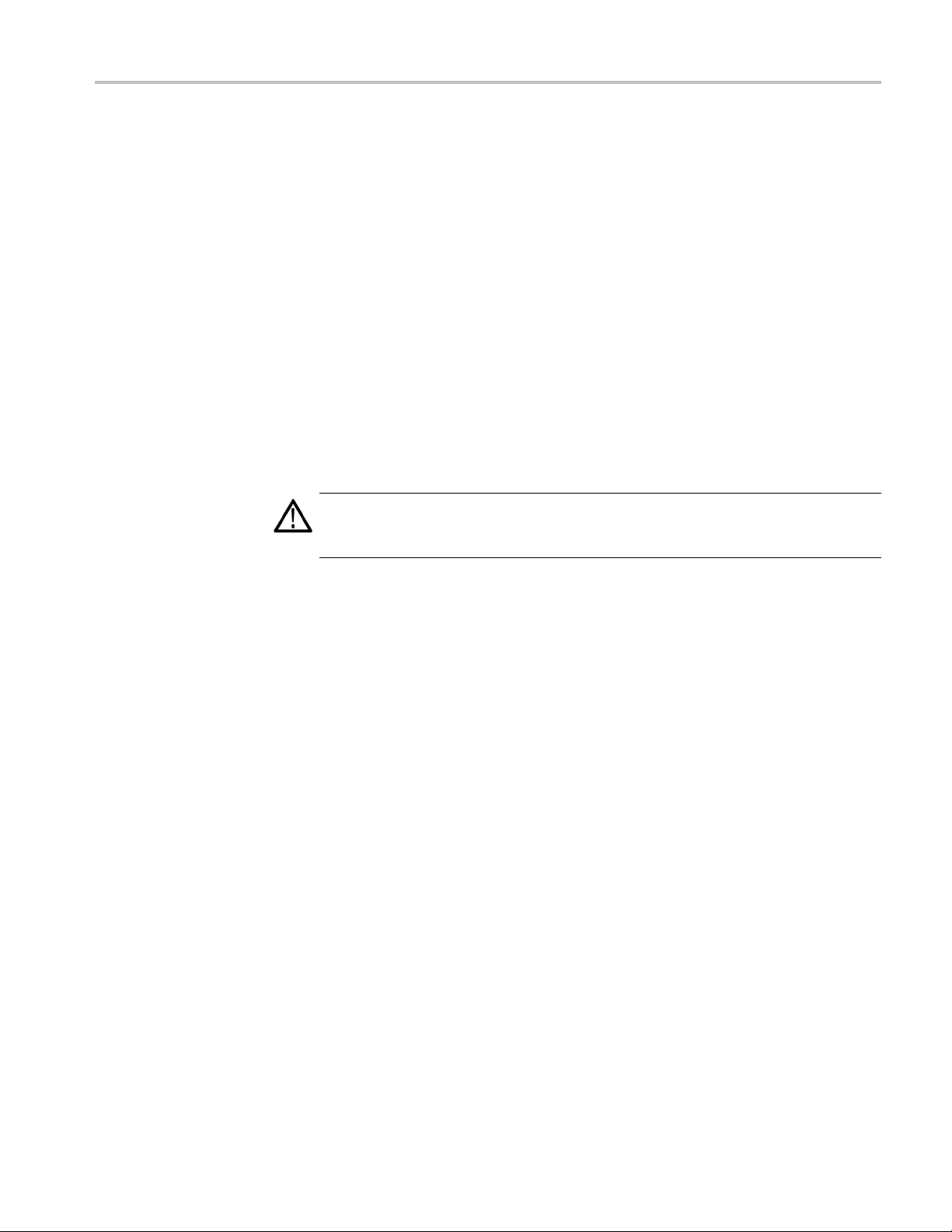
TLA7KUP Option 46: TLA Application Software Upgrade
1. Log on as Admini
2. Insert the first CD of the TLA Application software in the instrument.
3. Start Windows Explorer and browse to and execute D:\TLA Application
SW\Setup.exe.
4. Click Yes to start the installation.
5. Follow any on-screen instructions. If you are asked for permission to
overwrite any read-only files, select Ye s t o A l l .
6. After the software has been successfully installed, restart the instrument.
Upgrade the Instrument Firmware
Complete the following steps to upgrade the instrument firmware. Refer to
Update the TLA Module Firmware to upgrade module firmware. (See page 60.)
CAUTION. You MUST perform these steps to ensure that your Mainframe firm ware
has been upgraded. Failure to do so can result in the instrument not functioning
properly and the instrument might need to be repaired at the factory.
strator.
1. Log on as Administrator.
2. Exit the logic analyzer application.
3. Click Start → All Programs → Tektronix Logic Analyzer → TLA Firmware
Loader.
4. Select your instrument from the Firmware Loader - Connection d ialog box
and click Connect.
5. Click Load in the upper portion of the Load Firmware dialog box to identify
or to load mainframe firmware.
6. Compare the version numbers in the two columns. If the Running version
does not match the Required version, you MUST upgrade the firmware.
7. In the Frame column, click the Mainframe name that corresponds to the
firmware that requires upgrading and then click Update Firmware.
8. The next dialog box will have the correct .upd file selected in the file name
box. Click Open.
9. When the next window appears, click Start Flash Operation. The operation
may take several minutes.
10. Follow the remaining on-screen instructions.
11. Repeat the above steps for each mainframe firmware that is out of date.
TLA7KUP Logic Analyzer Field Upgrade Kit 59
Page 74

TLA7KUP Option 46: TLA Application Software Upgrade
Update TLA Module Firmware
Complete the following steps if the TLA startup messages indica te that you need
to upgrade module firmware You can update multiple modules and module types
during a single firmware update session.
NOTE. If you accidently closed the startup messages indicating which modules
need firmwar
1. Log on as Administrator.
2. Note the modules that require new firmware.
a. For TLA7Bxx/TLA7Axx/TLA7NAx series logic analyzer modules skip
b. For all other module types c ontinue with step 3.
3. Turn off the instrument and disconnect the power cord.
e upgrades, restart the TLA application.
steps 3 through 9 and go directly to step 10.
4. Remove the module requiring the upgrade from the instrument.
5. Locat
6. Install a jumper on the flash programming pins (use one of the spare jumpers
7. Reinstall the module(s) in the instrument.
8. Reconnect the power cord and then power on the logic analyzer.
NOTE. Any modules with the flash programming jumper installed will not display
in t
9. Log on as Administrator and then wait for the TLA application to start.
10. Exit the logic analyzer application.
11. Click Start → All Programs → Tektronix Logic Analyzer → TLA Firmware
12. Select your instrument from the Firmware Loader - Connection dialog box
13. Click Load in the lower portion of the Firmware Loader dialog box.
etheflash programming pins on the rear of the module. (See Figure 58.)
came with your logic analyzer).
that
he TLA or Pattern Generator System window.
Loader.
and click Connect.
14. Select the modules that you want to update from the list of modules displayed
in the Supported list box near the top of the menu. If you are updating more
than one module at a time, note the slot location of the module in the s election
box.
60 TLA7KUP Logic Analyzer Field Upgrade Kit
Page 75
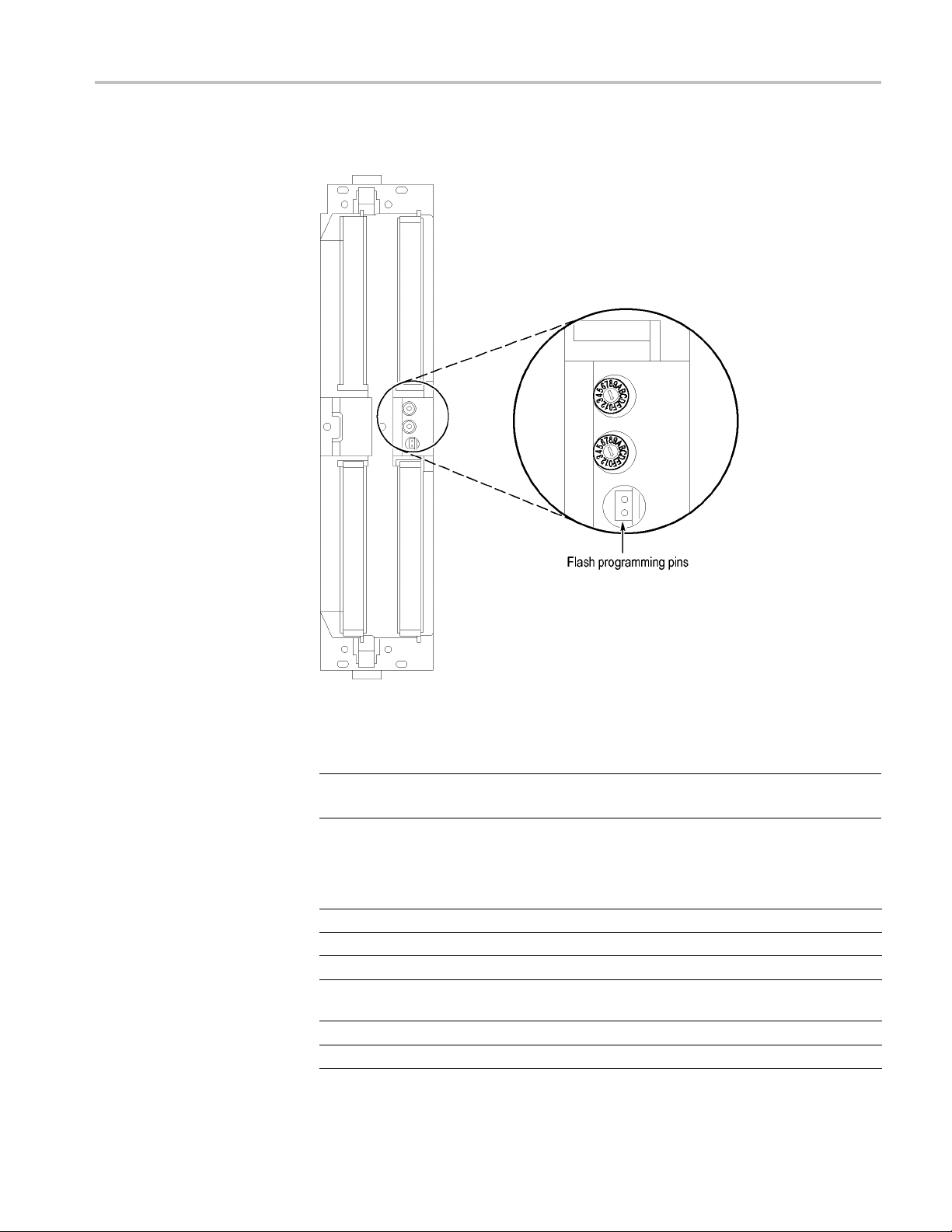
TLA7KUP Option 46: TLA Application Software Upgrade
15. Select Load Fir
mware from the Execute menu.
Figure 58: Flash programming pins
16. Click the proper .lod file for the selected module. (See Table 9.)
NOTE. Be sure to select the proper .lod file for each module. Note the slot number
in the title bar so that you select the correct module for the .lod file.
Table 9: TLA firmware files
Module type .lod file
TLA7NAx logic analyzer modules TLA7NAX.lod
TLA7Axx logic analyzer modules TLA7AXX.lod
TLA7Bxx logic analyzer modules TLA7BXX.lod
TLA7Nx, TLA7Px, TLA7Qx logic analyzer
modules
TLA7Lx and TLA7Mx logic analyzer modules TLA7LM.lod
TLA7Dx and TLA7Ex DSO modules FirmwareDSO.lod
TLA7NPQ.lod
TLA7KUP Logic Analyzer Field Upgrade Kit 61
Page 76

TLA7KUP Option 46: TLA Application Software Upgrade
Table 9 : TLA firmware files (cont.)
Module type .lod file
TLA7PG2 Pattern Generator modules
1
The .lod files for the pattern generator modules are located in the C:\Program Files\Tektronix Pattern
Generator\Firmware folder. All other filesarelocatedintheC:\Programfiles\TLA 700\Firmware folder.
17. Click Open. Whenpromptedtoconfirm your action; click Yes .
NOTE. The program will not allow you to load firmware to an incompatible
module. For example, the program will not load DSO firmwaretoalogicanalyzer
module.
The program will load the firmware for each module one at a time. The
process may take several minutes per module.
18. When the upgrade is complete, exit the firmware loader program.
1
tla7pg2.lod
19. Turn of
f the instrument and disconnect the power cord.
20. Remove the module from the instrument.
21. For all modules except the TLA7Bxx, TLA7Axx or TLA7NAx modules,
remove the jumper from the Flash programming pins on the rear of the
le. Keep the jumper for future updates.
modu
22. Reinstall the module in the instrument, tighten the hold-down screws, and
n reconnect the probes.
the
23. Reconnect the power cord and power on the instrument.
24. Verify that the power-on diagnostics pass.
62 TLA7KUP Logic Analyzer Field Upgrade Kit
Page 77

TLA7KUP Option 46: TLA Application Software Upgrade
Upgrading Fir
mware on the Interface Module and the TL708EX TekLink 8-Port Hub
Use the following procedure to upgrade the firmware on the benchtop mainframe
interface module and the hub.
1. Start the Firmware Loader.
2. A list of installed mainframes displays. Select the mainframe you want to
upgrade and click Connect.
3. The Firmware Loader dialog box appears. You have the choice to load
Mainframe or Instrument Module firmware. Click the Load button
corresponding to Mainframe and TekLink firmware.
4. A list of all the currently installed Mainframe and TekLink firmware displays.
The list shows the version currently running and the version available for
ation. Select the items you wish to load.
install
5. Click the Update Firmware button. A file dialog box displays a list of
firmwar
6. Select the appropriate file. Click Open to open the selected firmware image.
You m u
7. The Firmware Load Progress dialog displays. Click the Start Flash Operation
butt
operation is started it cannot be canceled.
eimagesavailable.
st do this for each firmware image selected.
on to start the flash operation for the selected flash images. Once the flash
8. As t
9. Tur
he flash operation runs, it identifies what steps are being performed. When
complete, it will inform you to reboot the system you just flashed.
n off and restart the TLA system after the flash operation is complete.
TLA7KUP Logic Analyzer Field Upgrade Kit 63
Page 78

TLA7KUP Option 46: TLA Application Software Upgrade
Calibrate the
Instrument
After verifying proper operation, you need to calibrate the logic analyzer.
1. Allow the instrument to warm up for at least 30 minutes before continuing.
2. In the System window, select Calibration and Diagnostics from the System
menu.
3. Click the Self Calibration tab.
4. Select the Run button and click Yes to any confirmation messages.
NOTE. The calibration process may take several minutes.
The Status column indicates Running while the instrument is being calibrated.
5. Verify t
6. Close the dialog box.
hat the Status column changes to Calibrated.
Installing the TLA Application Software on a PC
Install Third-Party Software
You can install the TLA application software on a PC for the following purposes:
To run the TLA application software in the Offline mode.
To control a logic analyzer with the same TLA application software version
over a network.
To use all of the features of the TLA application software on your PC, you must
install additional third-party software. The following third-party software is
available on the TLA Application Software CD:
The NI-GPIB software allows you to use the iView software with your PC.
The SnagIt software is useful for copying screen shots of logic analyzer data
for use with other applications.
NOTE. Several third-party software applications are included to use with your
logic analyzer. These applications may include software license agreements. Be
sure to abide by those license agreements.
64 TLA7KUP Logic Analyzer Field Upgrade Kit
Page 79

TLA7KUP Option 46: TLA Application Software Upgrade
Install the NI-
software on your PC:
1. Insert the TLA
2. Browse to the NI-GPIB-USB folder on the CD and run the Setup.exe program.
3. Follow the on-screen instructions and note the items below:
a. When prompted, select the Typical installation option.
b. When the Add GPIB wizard appears, click Cancel.
c. After restarting the instrument, the NI-488.2 Getting Started wizard
d. When you first connect the iView cable, the instrument will detect the new
Install the SnagIt Software. Complete the following steps to install the SnagIt
softwa
1. Browse to the SnagIt folder on the CD and run the Setup.exe program.
2. Follow the on-screen instructions.
GPIB Software. Complete the following steps to install the third-party
Application Software CD in the CD drive.
displays. This is not needed; select Do not show at Windows startup
and then click X to exit..
hardware. Select Install the software automatically (Recommended).
re on your PC:
Install the TLA Application
Software
Start the TLA Application
Browse to the TLA Application software folder on the CD and run the Setup.exe
program. Follow the on-screen instructions to install the TLA application
software.
If you have an older version of the software on the hard disk, the installation
program will detect it and ask if you want to remove it. Follow the on-screen
instructions to remove the software, answering "Yes" to any prompts. Restart the
strument when prompted and run the Setup.exe program again.
in
If you have installed the TLA application s of tware on a PC for remote operation,
start the software by double-clicking on the TLA Application icon. The TLA
Connection dialog box displays.
1. Select an instrument in the TLA Connection dialog box and then click
Connect. If your instrument is connected to a network, you can connect to
any unused instrument on your local network.
2. Click Offline to start an offline version of the TLA application software.
The TLA Offline software allows you to run the TLA application without
connectingtoaninstrument.Youcananalyzepreviouslyacquireddatafroma
logic analyzer, create or modify reference memories, or perform system tests
without being connected to an instrument.
TLA7KUP Logic Analyzer Field Upgrade Kit 65
Page 80

TLA7KUP Option 46: TLA Application Software Upgrade
Attach the Upgrade Kit Label to the Instrument
After completing the previous steps, you need to install the upgrade kit label on
the instrument to indicate that the kit is installed.
1. Turn off the instrument and disconnect the power cord.
2. Remove any of the instrument modules where you have installed new
firmware.
3. Locate the big label on the side of instrument modules and then attach the
revision label and the TLA7KUP kit label as shown. (See Figure 59.)
4. Complete the following steps if you are updating a TLA7016 Logic Analyzer:
a. Remove th
b. Locate the big label on the side of the TLA7016 Interface Module and
attach t
Figure 59.)
NOTE. If there already is an upgrade kit label installed, install the new label
just above or below the old one. However, ensure that you install the software
revision label over the old revision label to indicate the current version of
software on your instrument.
5. Complete the following steps if you have a TLA7012 Portable Mainframe:
Locate the big label on the bottom of the portable mainframe and attach
the revision label and the TLA7KUP kit label as shown. (See Figure 59.)
NOTE. If there already is an upgrade kit label installed, install the new label
st above or below the old one. However, ensure that you install the software
ju
revision label over the old revision label to indicate the current version of
software on your instrument.
e TLA7016 Interface Module from the mainframe.
he revision label and the TLA7KUP kit label as shown. (See
66 TLA7KUP Logic Analyzer Field Upgrade Kit
Page 81

TLA7KUP Option 46: TLA Application Software Upgrade
Figure 59:
6. Reinstal
screws.
7. Reconne
8. Verify that all power-on dia gnostics pass.
Revision and kit label locations
l any modules that you removed earlier and tighten the hold-down
ct the power cord and power on the instrument.
TLA7KUP Logic Analyzer Field Upgrade Kit 67
Page 82

TLA7KUP Option 46: TLA Application Software Upgrade
68 TLA7KUP Logic Analyzer Field Upgrade Kit
Page 83

TLA7KUP Option 4C: iCapture Cables
TLA7KUP Option 4C adds four iCapture, BNC-to-BNC, low-loss, 10x cables for
your TLA7Axx or TLA7Bxx logic analyzer modules.
Instruments
Instruments Serial number range
TLA7012 Series Logic Analyzers with
TLA7Axx or TLA7Bxx logic analyzer modules
TLA7016 Series Logic Analyzers with
TLA7Axx o
Parts List
Table 10: TLA7KUP Option 4C parts list
Quantity Part number Description
4ea
1ea
r TLA7Bxx logic analyzer modules
N/A iCapture Analog OUtput, BNC-to-BNC, low-loss, 10x
cable,
N/A
TLA7KUP kit label
36-in.
All serial n
All serial numbers
umbers
Minimum Tool and Equipment List
No special tools or equipment are required to install this option.
TLA7KUP Logic Analyzer Field Upgrade Kit 69
Page 84

TLA7KUP Option 4C: iCapture Cables
70 TLA7KUP Logic Analyzer Field Upgrade Kit
Page 85

TLA7KUP Option IF: Upgrade Installation Service
TLA7KUP Option IF provides installation of product upgrades performed at
a Tektronix service location.
Instruments
NOTE. Avail
product and may vary by geography.
Instrumen
TLA7012 S
TLA7016 S
ability of installation and on-site services depend on the type of
ts
eries Logic Analyzers
eries Logic Analyzers
Serial num
All serial numbers
All serial numbers
ber range
TLA7KUP Logic Analyzer Field Upgrade Kit 71
Page 86

TLA7KUP Option IF: Upgrade Installation Service
72 TLA7KUP Logic Analyzer Field Upgrade Kit
Page 87

TLA7KUP Option IN: On-Site Installation Service
TLA7KUP Option IN provides initial product installation/configuration and start
up training session including front panel and product familiarization at your site
(excludes ne
NOTE. Availability of installation and on-site services depend on the type of
product and may vary by geography.
twork integration).
Instrumen
ts
Instruments Serial number range
TLA7012 Series Logic Analyzers
TLA7016 Series Logic Analyzers
TLA7PC1
All serial numbers
All serial numbers
All serial numbers
TLA7KUP Logic Analyzer Field Upgrade Kit 73
 Loading...