


xx
TLA7Bxx
ZZZ
Logic Analyzer Module
Service Manual
This document applies to TLA System Software Version 5.6
or higher
Warning
These servicing instructions are for use by qualified personnel
only. To avoid personal injury, do not perform any servicing
unless you are qualified to do so. Refer to all safety summaries
prior to performing service.
www.tektronix.com
077-0147-00

Copyright © Tektronix. All rights reserved. Licensed software products are owned by Tektronix or its subsidiaries
or suppliers, and are protected by national copyright laws and international treaty provisions.
Tektronix products are covered by U.S. and foreign patents, issued and pending. Information in this publication
supersedes that in all previously published material. Specifications and price change privileges reserved.
TEKTRONIX and TEK are registered trademarks of Tektronix, Inc.
Contacting Tektronix
Tektronix, Inc.
14200 SW Karl Braun Drive
P.O . Bo x 500
Beaverto
USA
For product information, sales, service, and technical support:
n, OR 97077
In North America, call 1-800-833-9200.
World wi de, vis i t www.tektronix.com to find contacts in your area.

Warranty 2
Tektronix warrants that this product will be free from defects in materials and workmanship for a period of one (1)
year from the date of shipment. If any such product proves defective during this warranty period, Tektronix, at its
option, either will repair the defective product without charge for parts and labor, or will provide a replacement
in exchange for the defective product. Parts, modules and replacement products used by Tektronix for warranty
work may be n
the property of Tektronix.
ew or reconditioned to like new performance. All replaced parts, modules and products become
In order to o
the warranty period and make suitable arrangements for the performance of service. Customer shall be responsible
for packaging and shipping the defective product to the service center designated by Tektronix, with shipping
charges prepaid. Tektronix shall pay for the return of the product to Customer if the shipment is to a location within
the country in which the Tektronix service center is located. Customer shall be responsible for paying all shipping
charges, duties, taxes, and any other charges for products returned to any other locations.
This warranty shall not apply to any defect, failure or damage caused by improper use or improper or inadequate
maintenance and care. Tektronix shall not be obligated to furnish service under this warranty a) to repair damage
result
b) to repair damage resulting from improper use or connection to incompatible equipment; c) to repair any damage
or malfunction caused by the use of non-Tektronix supplies; or d) to service a product that has been modified or
integrated with other products when the effect of such modification or integration increases the time or difficulty
of servicing the product.
THIS WARRANTY IS GIVEN BY TEKTRONIX WITH RESPECT TO THE PRODUCT IN LIEU OF ANY
OTHER WARRANTIES, EXPRESS OR IMPLIED. TEKTRONIX AND ITS VENDORS DISCLAIM ANY
IMPLIED WARRANTIES OF MERCHANTABILITY OR FITNESS FOR A PARTICULAR PURPOSE.
TRONIX’ RESPONSIBILITY TO REPAIR OR REPLACE DEFECTIVE PRODUCTS IS THE SOLE
TEK
AND EXCLUSIVE REMEDY PROVIDED TO THE CUSTOMER FOR BREACH OF THIS WARRANTY.
TEKTRONIX AND ITS VENDORS WILL NOT BE LIABLE FOR ANY INDIRECT, SPECIAL, INCIDENTAL,
OR CONSEQUENTIAL DAMAGES IRRESPECTIVE OF WHETHER TEKTRONIX OR THE VENDOR HAS
ADVANCE NOTICE OF THE POSSIBILITY OF SUCH DAMAGES.
btain service under this warranty, Customer must notify Tektronix of the defect before the expiration of
ing from attempts by personnel other than Tektronix representatives to install, repair or service the product;


Table of Contents
General Safety Summary ......................................................................................... iii
Service Safety Summary.......... ................................ ................................ ................. v
Preface ............................................................................................................. vii
Manual Conv
Related Documentation ..................................................................................... vii
Introduction ........................................................................................................ ix
Service Offerings ............................................................................................. ix
Maintenance......................................................................................................... 1
Preventing ESD ................................................................................................ 1
Inspect
Removal and Installation ................. .................................. ................................ ....... 5
Tools Required ................................................................................................. 5
Torque Requirements.......................................................................................... 5
Top Covers .... .................................. ................................ ............................... 5
Local Processor Unit (LPU) Board .......................................................................... 8
isition Board ... ... . ... . ... .... ... . ... . ... .... ... . ... . ... . . ... ... . ... . ... . . ... ... . ... . ... . . ... ... . ... . ... . 9
Acqu
EMI Gaskets................................................................................................... 11
Troubleshooting.................................................................................................... 13
Check for Common Problems ................. ................................ .............................. 14
Eliminate Other Problem Sources........................................................................... 15
Troubleshoot the Module .................................................................................... 15
justment After Repair....... ................................ .................................. ............ 22
Ad
Updating the Module Firmware....... ................................ .................................. .... 23
Repackaging Instructions......................................................................................... 24
Parts List............................................................................................................ 25
Parts Ordering Information .................................................................................. 25
Using the Replaceable Parts List............................................................................ 26
entions.............. ................................ .................................. ......... vii
ion and Cleaning.............. .................................. ................................ ....... 1
TLA7Bxx Logic Analyzer Module Service Manual i

Table of Contents
List of Figure
Figure 1: EMI gasket and bracket ....................... ................................ ........................ 27
Figure 2: Fl
Figure 3: Top cover and rear panel ................ ................................ .............................. 29
Figure 4: LPU board .............................................................................................. 30
Figure 5: Acquisition board . ... . ... .... ... . ... ... . ... ... . ... ... . ... . ... ... . ... ... . ... ... . ... . ... ... . ... ... . ... ... 32
ex cable and bracket................................................................................. 28
List of Tables
Table 1: External inspection checklist................. .................................. ......................... 2
Table 2: Internal inspection checklist . ................................ .................................. ......... 3
Table 3
Table 4: Failure symptoms and possible causes........................................ ........................ 14
Table 5: Diagnostic tests.......................................................................................... 20
Table 6: Requirements after replacement. ................................ ................................ ...... 22
Table 7: Parts list column descriptions...... ................................ ................................ .... 26
: Tools required for circuit board replacement................................. ......................... 5
s
ii TLA7Bxx Logic A nalyzer Module Service Manual

General Safety Summary
General Safet
To Avoid Fire or Personal
Injury
ySummary
Review the fo
this product or any products connected to it.
To avoid pot
Only qualified personnel should perform service procedures.
While using this product, you may need to access other parts of a larger system.
Read the safety sections of the other component manuals for warnings and
cautions r
Ground the Product. This product is indirectly grounded through the grounding
conductor of the mainframe power cord. To avoid electric shock, the grounding
conductor must be connected to earth ground. Before making connections to
the input or output terminals of the product, ensure that the product is properly
ground
Observe All Terminal Ratings. To avoid fire or shock hazard, observe all ratings
and ma
information before making connections to the product.
The i
ed.
nputs are not rated for connection to mains or Category II, III, or IV circuits.
llowing safety precautions to avoid injury and prevent damage to
ential hazards, use this product only as specified.
elated to operating the system.
rkings on the product. Consult the product manual for further ratings
Terms in this Manual
Do not apply a potential to any terminal, including the common terminal, that
eeds the maximum rating of that terminal.
exc
Power Disconnect. The power cord disconnects the product from the power source.
ot block the power cord; it must remain accessible to the user at all times.
Do n
Do Not Operate Without Covers. Do not operate this product with covers or panels
moved.
re
Do Not Operate With Suspected Failures. If you suspect that there is damage to this
roduct, h ave it inspected by qualified service personnel.
p
Avoid Exposed Circuitry. Do not touch exposed connections and components
when power is present.
Do Not Operate in Wet/Damp Conditions.
Do Not Operate in an Explosive Atmosphere.
Keep Product Surfaces Clean and Dry.
Provide Proper Ventilation. Refer to the manual’s installation instructions for
details on installing the product so it has proper ventilation.
These terms may appear in this manual:
TLA7Bxx Logic Analyzer Module Service Manual iii
General Safety Summary
WARNING. Warning statements identify conditions or practices that could result
in injury or lo
CAUTION. Caution statements identify conditions or practices that could result in
damage to th
ss of life.
is product or other property.
Symbols and Terms on the
Product
These terms may appear on the product:
DANGER indicates an injury hazard immediately accessible as you read
the marking.
WARNING indicates an injury hazard not immediately accessible as you
read the marking.
CAUTION indicates a hazard to property including the product.
The following symbol(s) may appear on the product:
iv TLA7Bxx Logic Analyzer Module Service Manual

Service Safety Summary
Service Safet
y Summary
Only qualifie
Safety Summary and the General Safety Summary before performing any service
procedures.
Do Not Service Alone. Do not perform internal service or adjustments of this
product unless another person capable of rendering first aid and resuscitation is
present.
Disconnect Power. To avoid electric shock, switch off the instrument power, then
disconnect the power cord from the mains power.
UseCareWhenServicingWithPowerOn. Dangerousvoltagesorcurrentsmay
exist in
disconnect test leads before removing protective panels, soldering, or replacing
components.
To avoid electric shock, do not touch exposed connections.
d personnel should perform service procedures. Read this Service
this product. Disconnect power, remove battery (if applicable), and
TLA7Bxx Logic Analyzer Module Service Manual v

Service Safety Summary
vi TLA7Bxx Logic Analyzer Module Service Manual

Preface
Preface
Manual Conventions
Acquisition Board
LPU Board
Maintenance Procedures
This manual c
TLA7Bxx logic analyzer modules. It provides information for the removal and
replacement of circuit boards, assemblies, and mechanical parts listed in the parts
lists. It does not support component-level fault isolation and replacement.
This manual uses certain conventions that you should be familiar with before
service the instrument.
The acquisition board is one of the circuit boards inside the instrument module.
The circuit board receives and stores acquisition data
with the Local Processor Unit (LPU) board to provide information to the operator.
The Local Processor Unit (LPU) board is one of the circuit boards inside the
instrument module that provides the main communications interface with the
acquisition board and the mainframe.
Maintenance procedures are used for fault isolation and repair to the circuit board
level or to the replaceable part level.
ontains information needed for periodic maintenance of the
from the probes and works
Modules
Replaceable Parts
Related Documentation
Throughout this manual, the terms “module” and “instrument module” refer to
a logic analyzer, serial analyzer, or pattern generator unit that mounts inside a
mainframe. A module is composed of circuit boards, interconnecting cables, and
a user-accessible front panel.
This manual refers to any field-replaceable assembly or mechanical part
specifically by its name or generically as a replaceable part. In general, a
replaceable part is any circuit board or assembly that is listed in the replaceable
parts list near the end of this manual.
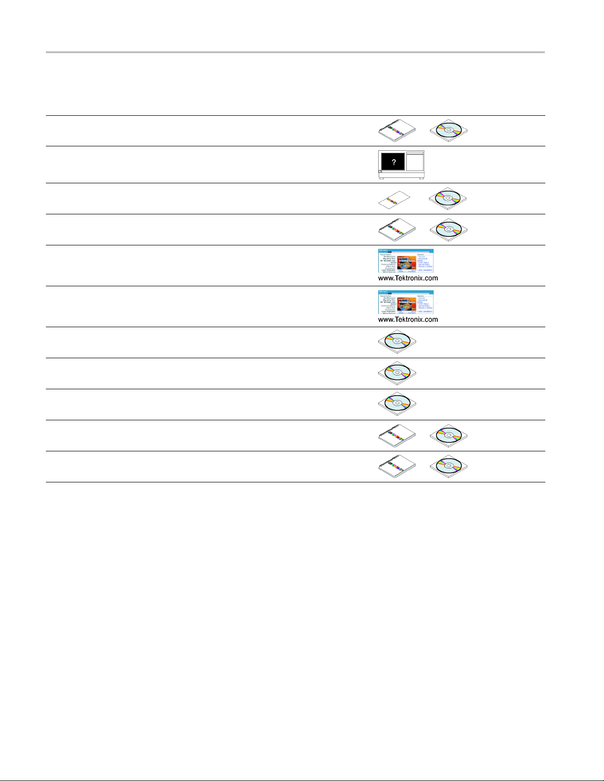
The following table lists related documentation available for your instrument. The
documentation is available on the TLA Documentation CD, included with your
instrument, and on the Tektronix Web site (www.Tektronix.com).
To obtain documentation not specified in the table, contact your local Tektronix
representative.
TLA7Bxx Logic Analyzer Module Service Manual vii
Preface
Related Docume
Item Purpose Location
TLA Quick Star
Online Help
Installati
Installation Manuals
XYZs of Logic Analyzers
Declassification and Securities
instructions
Applicat
Product Specifications & Performance
Verification Procedures
on Quick Reference Cards
ion notes
ntation
t User Manuals
High-level operational overview
In-depth operation and UI help
High-level
Detailed first-time installation information
Logic anal
Data security concerns specificto
sanitizing or removing memory devices
from Tektronix products
Collection of logic analyzer application
specific notes
TLA Product specifications and
performance v erification procedures
installation information
yzer basics
TPI.NET Documentation
Field upgrade kits
nal Service Manuals
Optio
Detailed information for controlling the
nalyzer using .NET
logic a
Upgrade information for your logic
analyzer
service documentation for modules
Selfand mainframes
viii TLA7Bxx Logic A nalyzer Module Service Manual

Introduction
This manual contains information needed to service the TLA7Bxx logic analyzer
modules.
Service Offerings
Warranty Repair Service
To prevent personal injury or damage to the instrument, consider the f
requirements before attempting service:
Read the General Safety Summary and Service Safety Summary located at
the beginning of this manual.
The procedures in this m anual should only be performed by a qualified service
person.
Be sure to follow all warnings, cautions and notes.
Tektronix provides service to cover repair under warranty as well as other services
that are designed to meet your specific service needs.
Tektronix service technicians are equipped to provide warranty and other services
at Tektronix Services Centers or on-site at your facility, depending on your
location.
Tektronix warrants this product for one year from d ate of purchase. The warranty
is located at the beginning of this manual. Tektronix technicians provide warranty
service at most Tektronix service locations worldwide. The Tektronix product
catalog lists all service locations worldwide.
ollowing
Calibration and Repair
Service
TLA7Bxx Logic Analyzer Module Service Manual ix
In addition to warranty repair, Tektronix Service offers calibration and other
services which provide solutions to your service needs and quality standards
compliance requirements.
The following services can be tailored to fit your requirements for calibration
and/or repair of your portable mainframe.
Service Options. Tektronix Service Options can be selected at the time you
purchase your instrument. You select these options to provide the services that
best meet your service needs.
Service Agreement. If service options are not added to the instrument purchase,
then service agreements are available on an annual basis to provide calibration
services or post-warranty repair coverage. Service agreements can be customized
to meet special turn-around time and/or on-site requirements.
Service on Demand. Tektronix offers calibration and repair services on a
“per-incident” basis that is available at standard prices.

Introduction
Self Service. T
for circuit board exchange.
Use this servi
remanufactured ones. Tektronix ships updated and tested exchange boards. Each
board comes with a 90-day service warranty.
For More Information. Contact your local Tektronix service center or sales
engineer for more information on any of these Calibration and Repair Services.
ektronix supports repair to the replaceable-part level by providing
ce to reduce down-time for repair by exchanging circuit boards for
x TLA7Bxx Logic Analyzer Module Service Manual

Maintenance
Preventing ESD
WAR N ING. To avoid electric shock, always power off the instrument and
disconnect the power cord before cleaning or servicing the instrument.
When perfor
adhere to the following precautions to avoid damaging internal circuit boards and
their components due to electrostatic discharge (ESD).
CAUTION. Many components within the instrument are susceptible to static
discharge damage.
Service the instrument only in a static-free environment. Observe standard
handling precautions for static-sensitive devices.
Minimize handling of static-sensitive circuit boards.
Transport and store static-sensitive circuit boards in their static protected
containers or on a metal tray. Label any package that contains static-sensitive
boards.
Discharge the static voltage from your body by wearing a grounded antistatic
wrist strap while handling these circuit boards.
Nothing capable of generating or holding a static charge should be allowed
on the work station surface.
Handle circuit boards by the edges when possible.
ming any service that requires internal access to the instrument,
Do not slide the circuit boards over any surface.
Avoid h andling circuit boards in areas that have a floororwork-surface
covering capable of generating a static charge.
Inspection and Cleaning
The instrument is inspected mechanically and electrically before shipment. It
should be free of marks or scratches and should meet or e xceed all electrical
specifications. To confirm this, inspect for physical damage incurred during
transit. Retain the packaging in case shipment for repair is necessary. If there
is damage or deficiency, contact your local Tektronix representative. Cleaning
procedures consist of exterior and interior cleaning. Periodic cleaning reduces
instrument breakdown and increases reliability. Clean the instrument as often as
needed, based on your operating environment. Cleaning procedure are provided
on the following pages.
TLA7Bxx Logic Analyzer Module Service Manual 1

Maintenance
Exterior Inspection
Thoroughly che
ck modules that appear to have been dropped or otherwise abused
to verify correct operation and performance. Immediately repair defects that
could cause personal injury or lead to further damage to the benchtop controller,
expansion module, or the mainframes that the module plugs into.
Table 1: External inspection checklist
Item Inspect for Repair acti
Front panel
Front and rear connectors
Accesso
ries
Cracks, scr
deformations, missing or
damaged retainer screws,
or ejector
Broken shells, cracked
insulati
contacts
Dirt in co
Missing items or parts of
items, bent pins, broken or
frayed
connectors
atches,
handles
on, and deformed
nnectors
cables, and damaged
Replace def
missing parts.
Replace d
Clear dirt out of connectors.
Replace
missing parts, frayed
cables.
on
ective or
efective parts.
damaged or
CAUTION. To prevent damage to electrical components from moisture during
nal cleaning, use only enough liquid to dampen the cloth or applicator.
exter
Exterior Cleaning
edure
Proc
Clean the exterior surfaces with a soft dry lint-free cloth or a soft-bristle brush.
y dirt remains, use a soft cloth or swab dipped in a 75% isopropyl alcohol
If an
solution. Use a swab to clean narrow spaces around controls and connectors. Do
not use abrasive cleaning compounds.
CAUTION. Avoid getting moisture inside the instrument during exterior cleaning;
use just enough moisture to dampen the cloth or swab.
Use only deionized water when cleaning. Use a 75% isopropyl alcohol solution
a cleanser and rinse with deionized or distilled water.
as
Do not use chemical cleaning agents; they may damage the chassis. Avoid
hemicals that contain benzene, toluene, xylene, acetone, or similar solvents.
c
2 TLA7Bxx Logic Analyzer Module Service Manual

Maintenance
Interior Inspection
Remove the modu
le covers to access the inside of the instrument for inspection
and cleaning. (See page 5, Top C ove r s.) Inspect the internal portions of the
modules and the mainframes for damage and wear. Defects should be repaired
immediately.
Table 2: Internal inspection checklist
Item Inspect for Repair acti
Circuit boa
Solder co
Wiring and cables Loose plugs or connectors
Chassis Dents, deformations, and
rds
nnections
Loose, broken, or corroded
solder conn
Burned circuit boards.
Burned, broken, or cracked
circuit-r
Cold sold
and burne
frayed wiring
damaged hardware
ections.
un plating.
er or rosin joints
d, broken, or
Return to a Tektronix
Service Cen
Return to a Tektronix
Service C
Firmly seat connectors.
Repair or
defective wires or cables.
Straighten, repair, or replace
defective hardware.
on
ter.
enter.
replace p arts with
CAUTION. To prevent damage from electrical arcing, ensure that circuit boards
and components are dry before applying power.
Interior Cleaning
Procedure
Use a dry, low-velocity stream of air to clean the interior of the modules and the
mainframes. Use a soft-bristle brush for cleaning around components. If you must
use a liquid for minor interior cleaning, use a 75% isopropyl alcohol solution and
rinse with deionized or distilled water.
TLA7Bxx Logic Analyzer Module Service Manual 3

Maintenance
4 TLA7Bxx Logic Analyzer Module Service Manual

Removal and Installation
This section provides detailed instructions for removing or installing parts of the
module after you have removed the module from the mainframe. Removal and
installation instructions are not provided for all replaceable parts. (See page 25,
Parts List.)
Tools Required
WAR N ING. Be
Summary and the General Safety Summary located at the front of this manual.
These servicing instructions are for use by qualified personnel only. To avoid
personal injury, do not perform any servicing unless you are qualified to do so.
When performing any service which requires internal access to the instrument,
avoid damaging internal circuit boards and their components by electrostatic
discharge (ESD). (See page 1, Preventing ESD.)
The following table lists the tools needed to replace the internal components
of the instrument.
Table 3: Tools required for circuit board replacement
Description Example
Screwdriver with a T-15 and T-10 Torx tips Standard tool
1/4-inch nut driver Standard tool
9/16-inch nut driver Standard tool
Needle-nose pliers
fore doing any procedures in this manual, read the Service Safety
Standard tool
Torque Requirements
Tighten all T-15 screws to 8 in-lbs. Tighten standoff posts to 8 in-lbs.
Tighten all T-10 screws to 4 in-lbs.
Top Covers
Removal
TLA7Bxx Logic Analyzer Module Service Manual 5
Refer to the exploded view of the module to remove the covers. (See Figure 3
on page 29.) To remove the merged bracket and cable, reverse the installation
steps in step 8.
CAUTION. To prevent damage to the board, do not push or pry the black heatsinks.

Removal and Installation
6 TLA7Bxx Logic Analyzer Module Service Manual

Removal and Installation
Installation
Refer to the fol
the covers. (See Figure 3 on page 29.)
NOTE. Install the cover tightly against the chassis. This will ensure that the
module fits into adjacent slots in the mainframe.
1. Place the module on its right side.
CAUTION. To prevent damage to the module during the installation process,
reinstall the cover exactly as described in steps 2 through 8.
If the cover is not properly seated, the module can be damaged when you install
it in a mai
2. Insert the cover at an angle such that the front edge of the cover engages
with the
cover in place.
3. Make su
chassis flanges.
lowing procedure and the exploded view of the module to install
nframe.
EMI gaskets on the back of the front panel. Push the rear of the
re that the cover is fully seated (no gaps) against the front and rear
4. While
nearest the front of the module (four on each side of the cover), to attach the
cover to the chassis.
5. Slide the rear panel on the chassis a nd install the two rear panel T-15
Torx-drive screws.
6. Gently squeeze the chassis flange and rear panel flange together while
tightening the screws on the sides. This ensures that the rear panel does not
rotate; otherwise the module may not seat properly when installed in the
mainframe.
7. Install the two remaining T-15 Torx-drive screws nearest the rear of the
module (one on each side of the cover).
8. Complete the following steps to install the left merge cable assembly: (See
Figure 2 on page 28.)
a. Feed the merge cable through the cover.
b. Carefully connect the merge cable to the circuit board.
c. Insert the bracket assembly into the hole in the cover.
d. Install the seven T-10 countersunk screws on the bracket.
9. Check and tighten all screws.
holding the cover in place, install the eight T-15 Torx-drive screws
TLA7Bxx Logic Analyzer Module Service Manual 7

Removal and Installation
Local Process
Installation
or Unit (LPU) Board
NOTE. When placing an order for a replacement LPU board or an LPU exchange
board from the Tektronix Exchange Center, you must supply the model number,
serial number, PowerFlex Option upgrade number and firmware level.
Removal
Refer to the exploded view of the module to remove the LPU board. (See Figure 4
on page 30.)
CAUTION. Handle the LPU board gently to avoid breaking the front panel LED
extension. Do not pry against the heat sinks on the Acquisition board.
Refer to the following bullets and the exploded view of the module to install the
LPU board. (See Figure 4 on page 30.)
1. Place the LPU board (component side down) over the chassis and insert the
tabs on the LPU board into the front subpanel.
2. Line up the pins on the 160-pin connector (JR751) from the LPU board to the
cquisition board and gently press the LPU board in place.
3. Install the five T-10 Torx screws to secure the LPU boa rd to the chassis.
4. Install the cover. (See page 5, Top Covers.)
NOTE. After replacing the LPU board, you must verify the proper PowerFlex
level. The PowerFlex configuration information is listed on the side panel of the
dule. This information should match the module-specific information on the
mo
System Properties tab in the TLA application.
f the PowerFlex level does not match the information on the side panel label, you
I
must return the entire module to your local Tektronix service center.
8 TLA7Bxx Logic Analyzer Module Service Manual

Acquisition Board
Removal and Installation
Removal
Refer to the following procedure and the exploded view of the module to remove
the acquisition board: (See Figure 5 on page 32.)
1. Remove the top cover. (See page 5, To p C ov e rs.)
2. Remove the Local Processor Unit Board. (See page 8, Local Processor Unit
(LPU) Board.)
3. To remove the merge cable assembly, turn the chassis over and remove the
two T-10 screws from the merge cable assembly bracket.
4. Using a 1/4 nut driver, remove the five spacer posts from the Acquisition
board.
5. Disconnect the five coaxial cables on the Acquisition board.
6. Remove t
7. Do these two tasks simultaneously:
Carefully slide the Acquisition board away from the front panel until the
probe connectors clear the front panel. Then slide the bottom merge connector
along
8. Lift the circuit board out of the chassis and unplug the bottom merge
conn
he five T-10 screws located near the front of the Acquisition board.
the rail until it is free.
ector from the back of the Acquisition board.
TLA7Bxx Logic Analyzer Module Service Manual 9

Removal and Installation
Installation
Refer to the fol
the Acquisition board: (See Figure 5 on page 32.)
1. Place the Acqu
the back side of the Acquisition board, and guide the merge connector into
the sliding rails.
2. Carefully slide the Acquisition board into the chassis until the probe
connectors fit snugly into the front panel slots.
NOTE. The compression gasket in the bottom cover requires extra pressure and
care to align the probe connectors on the Acquisition board to the front panel slots.
3. Install the five T-10 screws located near the front of the Acquisition board.
4. Install the five spacer posts that secure the Acquisition board to the chassis.
5. Connect the five output cables from the front panel to the Acquisition board.
6. Comple
a. Turn the chassis over.
b. Slide the bracket forward and install the two T-10 screws to hold the
bracket in place.
lowing procedure and the exploded view of the module to install
isition board into the chassis, connect the merge connector on
te the following steps to install the merge cable assembly:
7. Install the LPU board. (See page 8, Local Processor Unit (LPU) Board.)
8. Install the cover. (See page 5, Top Covers.)
10 TLA7Bxx Logic Analyzer Module Service Manual

EMI Gaskets
Removal and Installation
Removal
Installati
on
Refer to the exploded view of the module to remove the EMI gaskets: (See
Figure 1 on page 27.)
Use the following procedure and the exploded v iew of the module to install the
EMI gaskets: (See Figure 1 on page 27.)
1. Position each gasket so that the gasket fingers face the outside of the module.
CAUTION. To avoid breaking the gasket fingers, do not lift the fingers very high.
2. Pick up each gasket at the end where the gasket finger is curved upward.
Rotate the gasket onto the module. As you do this, lift up any fingers that
bind to the chassis or cover.
3. Slide each gasket gently from side to side to ensure that the gasket snaps
in place.
4. Reinstall the Acquisition board and the LPU board if you removed them to
install the rear EMI gaskets.
5. Install the cover. (See page 5, To p Co v ers .)
TLA7Bxx Logic Analyzer Module Service Manual 11

Removal and Installation
12 TLA7Bxx Logic Analyzer Module Service Manual

Troubleshooting
This section provides troubleshooting information at the circuit board level. Only
the parts listed in the parts list are replaceable.
In most cases, faults are isolated to circuit boards or assemblies, but not to
individual components on those boards. Fault isolation is to the following circuit
boards and replaceable parts:
LPU board
Acquisition board
Merge connectors
WAR N ING. Before doing any procedures in this manual, read the Service Safety
Summary and the General Safety Summary located at the beginning of this
manual.
When performing any service which requires internal access to the instrument,
avoid damaging internal circuit boards and their components by electrostatic
discharge (ESD). (See page 1, Preventing ESD.)
This section contains information and procedures designed to help isolate faults to
within the module. The processisasfollows:
1. Check for common problems. (See page 14, Check for Common Problems.)
2. Eliminate the mainframe, p robes, and other modules as the source of the
fault(s). (See page 15, Eliminate Other Problem Sources.)
3. Identify the failed replaceable part within the module. (See page 15,
Troubleshoot the Module.)
TLA7Bxx Logic Analyzer Module Service Manual 13

Troubleshooting
Check for Comm
on Problems
The following table lists common prob lems related to the instrument module
and possible causes. The list is not exhaustive, but it may help you eliminate
aproblemtha
CAUTION. To avoid damaging the instrument module or the mainframe, be sure to
power down the mainframe before removing or reinstalling any modules.
Table 4: Failure symptoms and possible causes
Symptom Possible cause(s)
Modules not recognized
Module does not pass the normal power on
diagnostics (READY indicator not green)
Module loses settings when power is turned
off
Module w ill not acquire data or the acquired
data is incorrect
tiseasytofix.
Modules not fully inserted; make sure front
of module is flush with front panel
Mainframe power supply failure; contact
local Tektronix service center
Corrupted module firmware; reinstall
firmware. (See page 23, Updating the
Module Firmware.)
Module logical address switches set to 00.
Reset the switches to FF.
Module not fully inserted; make sure front of
module is flush with front panel
Module failure. (See page 15, Troubleshoot
the Module.) If necessary, contact local
Tektronix service center
Module failure. (See page 15, Troubleshoot
the Module.) If necessary, contact local
Tektronix service center
NV RAM failure. Replace the LPU board.
(See page 8, Local Processor Unit (LPU)
Board.)
Module failure. (See page 15, Troubleshoot
the Module.) If necessary, contact local
Tektronix service center
Faulty probe, leadset, or probe adaptor
14 TLA7Bxx Logic Analyzer Module Service Manual

Troubleshooting
Eliminate Oth
er Problem Sources
Substitute Good Module
The module is part of the Tektronix Logic Analyzer Family, which consists
of one or more instrument modules installed in either a benchtop or portable
mainframe. T
other modules as possible sources of failures.
If you have a known-good module available, perform the following procedure:
1. Remove the suspect module from the mainframe.
2. Install a known-good module in the same slot as the suspected module (verify
that address s witches on the rear of the module are set to same address as
the module that you are replacing).
3. Power-on the instrument and check for normal operation.
4. If the failure symptoms are still present with the known-good module
installed, the problem most likely is in the mainframe or in the attached
probes, not in the module.
5. To eliminate the probes, use known-good probes and verify that the probes
are properly c onnected to the SUT.
he following procedures will help you eliminate the mainframe and
NOTE
isolate failures to individual modules or to the mainframe.
6. If t
Troubleshoot the Module
Follow the procedures in this section to identify the failed part within the
module. These procedure require that the module is installed in a fully functional
mainframe. If you have not determined that the mainframe is functional, or if
you suspect the problem might be in a probe or in another module, you need to
eliminate those possibilities. (See page 15, Eliminate Other Problem Sources.)
Equipment Required
The basic troubleshooting procedures require minimal test equipment. There are
no accessible test points to measure voltages.
. Viewing the diagnostic window from the TLA application can help you
he instrument operates normally with the known-good module and
with known-good probes, the suspect module needs to be repaired. (See
Troubleshoot the Module.)
TLA7Bxx Logic Analyzer Module Service Manual 15

Troubleshooting
Preparation
Diagnostic Procedures
The fault isola
Recognize codes flashed by the front-panel LED
Are familiar with the power-on diagnostics
To fill these requirements, read the following topics before performing the Fault
Isolation Procedure. (See page 17, Fault Isolation Procedure.)
The following diagnostic procedures will help you diagnose problems.
Self Calibration. Use self calibration to calibrate the installed modules. Run the
self calibration after a minimum of a 30 minute warm-up and before running the
extended diagnostics.
Power-On Diagnostics. Power-on diagnostics check basic functionality of the
instrument at every power on. If any failures occur at power on, the screen
displays the calibration and diagnostics property sheet.
You can display and run the calibration and diagnostics property sheet by selecting
Calibration and Diagnostics from the System menu, even if no diagnostic failures
occur when you power on the instrument.
Extended Diagnostics. The extended diagnostics execute more thorough tests
than the power-on diagnostics. Using the extended diagnostics, you can do the
following tasks:
tion procedure requires that you:
s during power up
Run tests individually or as a group
Run tests once or continuously
Run tests until f
One diagnostic test will fail if probes are a
diagnostics with probes disconnected from the module.
To run the extended diagnostics, do the following steps:
1. Disconnect the probes from the instrument.
2. Start the TLA application if it is not already running.
3. From the System menu, select Calibration and Diagnostics.
4. Select the Extended Diagnostics property page.
5. Select the individual tests, group of tests, or all tests.
6. Click the Run button.
While the tests are executing, the word Running displays adjacent to the tests.
When the tests are complete, either a Pass or Fail indication displays adjacent
to each test.
ailures occur
ttached. For best results, run the
16 TLA7Bxx Logic Analyzer Module Service Manual

Troubleshooting
Fault Isol
ation Procedure
Merged Modules
verifies the correct pipeline adjustment for the master module, inside slave
module, and outside slave module. This test does not require the modules to
be physically merged together.
Every time modules are merged in the System Configuration window, a calibration
is performed between the merged modules. An error message will appear if there
are any problems with the merge cables, circuit board traces, or if the calibration
fails.
The Primary Troubleshooting Tree provides troubleshooting steps that test the
module. Use the following procedure with the tree. To determine if module is
recognized, perform the following steps:
1. Install the module into a known-good mainframe.
2. Before you power on the mainframe, look at the READY, ACCESSED
ARM’D, and TRIG’D front panel indicators.
3. Poweronthemainframeandnotehowthe front-panel indicators respond.
a. Verify that the green READY indicator turns o n while the diagnostics
are being checked. If the green READY indicator does not turn on, the
module is not being recognized, which indicates possible p roblems on
the LPU board.
. The extended diagnostics include a special merge test that
b. Verify that after a few seconds, the ACCESSED indicator turns on. The
indicator stays on while the module is accessed by the controller. After
TLA application starts, the indicator blinks anytime the controller
the
accesses the module.
the previous steps are not verified, the module is not recognized. Proceed
4. If
as the troubleshooting tree instructs.
TLA7Bxx Logic Analyzer Module Service Manual 17

Troubleshooting
5. If diagnostic f
troubleshooting tree or see the diagnostics table. (See page 20, Diagnostics
Tab l e.)
Note from the tree, that if all the diagnostics pass, but self calibration fails,
replace the Acquisition board.
If any of the Kernel test groups fail (for example, ROM check, LPU RAM,
or LPU Address decode) replace the LPU board.
If the kernel group passes, but there are other failures, replace the acquisition
board.
NOTE. Ensure that the probes are disconnected from the module before running
the diagnostics.
If multiple tests fail, the problem could be related to power-supply problems
or the mainframe. If replacing the Acquisition board does not remedy the
failures, try replacing the LPU board.
NOTE.
to connect external test equipment to isolate faults to an individual circuit board.
Due to the module design, there are no accessible test points on the module
ailures occur, replace the circuit board indicated by the
6. Repl
ace the faulty circuit board. (See page 5, Removal and Installation.)
18 TLA7Bxx Logic Analyzer Module Service Manual

Troubleshooting
Primary Troubl
eshooting
Chart
TLA7Bxx Logic Analyzer Module Service Manual 19

Troubleshooting
Diagnostics Table
The following t
able will help you isolate a problem to one of the circuit boards in
the module.
Table 5: Diagnostic tests
Circuit board Group & test Power-on Extended
LPU board
Acquisition
board
Kernel Tests
ROM Check
LPU RAM
LPU Address Decode
NVRAM Check
Startup Te
Front-End
Clocking Tests
Datapath Tests
Trigger
Memor
sts
Power On St
ICC Diagnostics
Test s
Floating
CSM RAM
QC RAM
Clock Group Detect
Glitch Detection
Edge Detection
Crosspoint
Data Login
Data Pipeline
Setup/Hold Counter
Backplane
TSM RAM
PSM RAM
Word Recognizer
Transition Detector
Range Recognizer
TSM Co
Snapshot Recognizer
Fast Acquisition RAM
Slow Acquisition RAM
Stimulus
Test s
unters
yTests
atus
20 TLA7Bxx Logic Analyzer Module Service Manual

Troubleshooting
Table 5: Diagnostic tests (cont.)
Circuit board Group & test Power-on Extended
Fast MagniVu Write
Acquisition Tests
Unpack
At-Speed 1
At-Speed 2
At-Speed 3
Counter
Store 1
Store 2
Post Processing Tests
Ring Communication
Internal Data Transfer
Merge Tests
Merge Pipeline
Merge Signal Interface
TLA7Bxx Logic Analyzer Module Service Manual 21

Troubleshooting
Adjustment Af
ter Repair
After the replacing a circuit board or assembly due to electrical failure, perform
the indicated procedures in the following table.
Table 6: Req
Board replaced Adjustment required Verification checks
LPU board
Acquisit
1
The PowerFlex restoration or changes can only be made by Tektronix service personnel.
2
Refer to the TLA7UP Mainframe Field Upgrade Instruction Manual for instructions for updating module firmware.
uirements after replacement
Adjustment: Powerflex
Firmware level restoration
Deskew, Se
Threshold tests
ion board
Adjustment: Self Calibration,
Deskew, Threshold tests
lf Calibration,
1
2
Self Calibration, Power-on and
Extended Diagnostics, performance
verificati
Self Calibration, Power-on and
Extended Diagnostics, performance
verificat
on procedures
ion procedures
22 TLA7Bxx Logic Analyzer Module Service Manual

Updating the Module Firmware
After you install support software and restart the instrument, you might be
prompted that your current module firmware is unsupported by the currently
installed software. A new version of the firmware must be installed on the
instrument so that it will work with the latest support software.
1. If you have not already done so, exit the TLA application.
2. Click Start >All Programs >Tektronix Logic Analyzer >TLA Firmware
Loader.
3. Select your mainframe instrument from the TLA Connection dialog box.
You are given a choice to load Mainframe or Instrument Module Firmware.
Click the Load button in the Instrument Module Firmware section (bottom
part of the dialog box).
4. You may be prompted about cycling the power on the mainframe after
completing the upgrade operation. Click Yes to continue.
The instrument will scan the mainframe to detect all installed modules, and to
determine which modules have firmware that needs to be upgraded.
Troubleshooting
5. Select your module(s) from the list displayed in the Supported list box near
the top of the window. If you are updating the firmware for more than one
module, note the locations of the modules in the mainframe and select them
the list.
from
6. Select Load Firmware from the Execute menu.
7. Navigate to C:\Program Files\TLA 700\Firmware and select the file named
TLA7BBx.lod.
TE. Be sure to correctly associate your module with this file. Note the slot
NO
number in the title bar so that you select the correct module.
lick OK. You will be prompted to confirm your action; click Yes.
8.C
The program will begin to load the firmware. The process can take several
minutes.
9. When the process is complete, the firmware has been loaded for the module.
Exit the firmware loader program and power off the instrument. You must
power off the instrument to allow the software application to start up properly.
TLA7Bxx Logic Analyzer Module Service Manual 23

Repackaging Instructions
Repackaging Instructions
If at all possible, use the original packaging to ship or store the instrument. If the
original packaging is not available, use a corrugated cardboard shipping carton
having a test
at least six inches (15.25 cm) greater than the instrument dimensions. Add
cushioning material to prevent the instrument from moving around in the shipping
container. Seal the shipping carton with an industrial stapler or strapping tape.
strength of at least 275 pounds (125 kg) and with an inside dimension
Shipping the Instrument to
the Service Center
Storage
Contact the Service Center to get an RMA (return material authorization) number,
and any return or shipping information you may need.
If the instrument is being shipped to a Tektronix Service Center, enclose the
following information:
The RMA number
The own
Name and phone number of a contact person
Type of instrument and serial number
Reason for returning
A complete description of the service required
Mark the address of the Tektronix Service Center and the return address on the
shipping carton in two prominent locations.
n not used in a mainframe, store the logic analyzer module in a clean, dry
Whe
environment. The following environmental characteristics apply for both shipping
and storage:
Temperature range: -40 °F to +160 °F (-40 °C to +71 °C)
er’s address
ltitude: To 9843 feet (3000 meters)
A
24 TLA7Bxx Logic Analyzer Module Service Manual

Parts List
This section contains a list of the replaceable parts for the TLA7BXX Logic
Analyzer Modules. Use this information to order replacement parts for your
instrument.
Parts Ordering Information
Parts List
Part Number Revision
Leve
Replacemen
or representative. Changes to Tektronix products are sometimes made to
accommodate improved components as they become available and to give you the
benefit of the latest improvements. Therefore, when ordering parts, it is important
to include the following information in your order:
Part number (see Part Number Revision Level below)
Instrument type or model number
Instrument serial number
Instru
If you order a part that has been replaced with a different or improved part, your
local
change in part number.
Tektronix part numbers contain two digits representing the revision level of the
t. For most parts in this manual, you will find the letters XX in place of the
par
l
revision level number.
t parts are available through your local Tektronix field office
ment modification number, if applicable
Tektronix field office or representative will contact you concerning any
When you order parts, Tektronix will provide you with the most current part for
your product type, serial number, and modification (if applicable). At the time of
your order, Tektronix will determine the part number revision level needed for
your product, based on the information you provide.
TLA7Bxx Logic Analyzer Module Service Manual 25

Parts List
Using the Replaceable Parts List
The following table describes each column in the replaceable parts lists.
Table 7: Parts list column descriptions
Column number Column name Description
1
2 Tektronix part number Use this part number when ordering
3 and 4
5
6
Figure & index number
Serial number Column 3 indicates the serial number at
Qty Quantity of parts used.
Name & description An item name is separated from the
Figure and index numbers in the exploded
view illustrations.
replacement parts from Tektronix.
which the part was first effective. Column
4 indicates the serial number at which
the part was discontinued. No entries in
either column indicates the part is good
for all serial numbers.
description by a colon (:). Because of
space limitations, an item name may
sometimes appear incomplete. U se the
U. S. Federal Catalog Handbook H6-1 for
further item name identification.
Abbreviations
Fig. &
number
1–1 407-5179-XX 1
1–2 211-0409-XX 2
1–3 131-6643-XX 6
1–4 870-6211-XX 1
1–5 211-0409-XX 2
1–6 348-1537-XX 8
1–7 348-1365-XX 1
index
onix part
Tektr
number
Abbreviations conform to American National Standard ANSI Y1.1-1972.
Serial
no.
effective
lno.
Seria
discont’d Qty Name & description
KET ( MERGE, CHASSIS, RIGHT SIDE)
BRAC
SCR, ASSEM WSHR; 4-40 X 0.312, PNH, 410 SS
SI VATED, T-10 TORX DR
PAS
CONTACT,ELEC; GROUNDING,0.169 L,0.320
EP,ELECTROLESS NICKEL;TDS 3012
DE
CIRCUIT BD ASSY; MERGE, RIGHT, TESTED FLEX,
9019800
25
SCR, ASSEM WSHR; 4-40 X 0.312, PNH, 410 SS
ASSIVATED, T-10 TORX DR
P
GASKET, EMI; CLIP-ON, 1.98 L, BE CU, TIN
PLATED, W/T LANCES
SHLD GSKT, ELEC; SYMETRICAL SLOTTED
FINGER, 0.350 W X 7.5 L, RIVIT MTG, SNAP-IN,
RIVIT SPACING 1.5 INC H , BECU
26 TLA7Bxx Logic Analyzer Module Service Manual

Parts List
Figure 1: EMI gasket and bracket
TLA7Bxx Logic Analyzer Module Service Manual 27

Parts List
Fig. & index
number
2-1 407-5177-XX 1
2-2 211-0734-XX
2-3 211-0409-X
2-4 870-6210-
Tektronix part
number
X
XX
Serial no.
effective
Serial no.
discont’d Qty N ame & descrip
tion
BRACKET (MERGE, COVER, LEFT SIDE)
7
SCREW, MACHINE; 6-32 X 0.250, FLH100, 410 SS
PASSIVATED, T-10 TORX DR
2
SCR, ASSEM WSHR; 4-40 X 0.312, PNH, 410 SS
PASSIVATED, T-10 TORX DR
1
CIRCUIT BD ASSY; MERGE, LEFT, TESTED FLEX,
259019700, LEAD FREE
Figure 2: Flex cable and bracket
28 TLA7Bxx Logic Analyzer Module Service Manual

Fig. & ind ex
number
Tektronix par
number
t
Serial
no.
effective
Parts List
Serial no.
discont’d Qty Name & description
3-1 200-5004-XX 1
3-2 211-0722-XX 12
3-3 348-1365-XX 1
3-4 386-7490-XX 1
COVER (TWO WID
SCREW, MACHINE; 6-32 X 0.250, PNH, 410 SS
PAS SIVATED
SHLD GSKT, ELEC; SYMETRICAL SLOTTED
FINGER, 0.3
SPACING 1.5 IN CH , BECU
BRACKET, E
E), SAFETY CONTROLLED
,T-15TORXDR
50 W X 7.5 L, RIVIT MTG, SNAP-IN, RIVIT
ND (TWO WIDE)
Figure 3: Top cover and rear panel
TLA7Bxx Logic Analyzer Module Service Manual 29

Parts List
Tektronix part
Fig. & index nu
4–1 870-6298-XX 1
4–2 211-0409-XX
mber
number
Serial no.
effective
Serial no.
discont’d Qty Name & descrip
tion
CIRCUIT BD ASSY; LPU
BOARD,TESTED
FREE, BORG
5
SCR, ASSEM W
SS PASSIVATED, T-10 TORX DR
,WIRED;389395700;LEAD
SHR; 4-40 X 0.312, PNH, 410
Figure 4: LPU board
30 TLA7Bxx Logic Analyzer Module Service Manual

Parts List
Tektronix part
Fig. & index nu
5-1 870-6199-XX 1
5-2 129-1478-XX
5-3 211–0409-XX
5-4 441-2481-XX 1
mber
number
870-6201-XX 1
870-6202-XX 1
870-0282-XX 1
Serial no.
effective
Serial no.
discont’d Qty Name & descrip
tion
CKD BD ASSY; ACQ BD,68CH TESTED,
TLA7BB2
CKD BD ASSY; ACQ BD,102CH TESTE D,
TLA7BB3
CKD BD ASSY; ACQ BD,136CH TESTE D,
TLA7BB4
CKD BD ASSY; ACQ BD,136CH TESTE D,
TLA7BC4
5
SPACER, POST; 1.738 L,1.113 SPACING,W/
0.35 L,0.
EXTERNAL THD,NICKEL;
5
SCR, ASS
SS PASSIVATED, T-10 TORX DR
CHASSI
SAFETY CONTROLLED
25 HEX,W/ 4-40 INT THD X 6-32
EM WSHR; 4-40 X 0.312, PNH, 410
S, ASSEMBLY (136 CHANNELS),
TLA7Bxx Logic Analyzer Module Service Manual 31

Parts List
Figure 5: Acquisition board
32 TLA7Bxx Logic Analyzer Module Service Manual
 Loading...