

Page 1

xx
TLA7ACx
ZZZ
Tektronix Logic Analyzer Module
Service Manual
This document applies to TLA application software version 5.6
and above.
Warning
The servicing instructions are for use by qualified personnel
only. To avoid personal injury, do not perform any servicing
unless you are qualified to do so. Refer to all safety summaries
prior to performing service.
www.tektronix.com
077-0158-00
Page 2

Copyright © Tektronix. All rights reserved. Licensed software products are owned by Tektronix or its subsidiaries
or suppliers, and are protected by national copyright laws and international treaty provisions.
Tektronix products are covered by U.S. and foreign patents, issued and pending. Information in this publication
supersedes that in all previously published material. Specifications and price change privileges reserved.
TEKTRONIX and TEK are registered trademarks of Tektronix, Inc.
Contacting Tektronix
Tektronix, Inc.
14200 SW Karl Braun Drive
P.O . B ox 50 0
Beaverto
USA
For product information, sales, service, and technical support:
n, OR 97077
In North America, call 1-800-833-9200.
World wide , vis i t www.tektronix.com to find contacts in your area.
Page 3

Warranty
Tektronix warrants that this product will be free from defects in materials and workmanship for a period of one (1)
year from the date of shipment. If any such product proves defective during this warranty period, Tektronix, at its
option, either will repair the defective product w ithout charge for parts and labor, or will provide a replacement
in exchange for the defective product. Parts , modules and replacement products used by Tektronix for warranty
work may be n
the property of Tektronix.
ew or reconditioned to like new performance. All replaced parts, modules and products become
In order to o
the warranty period and make suitable arrangements for the performance of service. Customer shall be responsible
for packaging and shipping the defective product to the s ervice center designated by Tektronix, with shipping
charges prepaid. Tektronix shall pay for the return of the product to Customer if the shipment is to a location within
the country in which the Tektronix service center is located. Customer shall be responsible for paying all shipping
charges, duties, taxes, and any other charges for products returned to any other locations.
This warranty shall not apply to any defect, failure or damage caused by improper use or improper or inadequate
maintenance and care. Tektronix shall not be obligated to furnish service under this warranty a) to repair damage
result
b) to repair damage resulting from improper use or connection to incompatible equipment; c) to repair any damage
or malfunction caused by the use of non-Tektronix supplies; or d) to service a product that has been modified or
integrated with other products when the effect of such modification or integration increases the time or difficulty
of servicing the product.
THIS WARRANTY IS GIVEN BY TEKTRONIX WITH RESPECT TO THE PRODUCT IN LIEU OF ANY
OTHER WARRANTIES, EXPRESS OR IMPLIED. TEKTRONIX AND ITS VENDORS DISCLAIM ANY
IMPLIED WARRANTIES OF MERCHANTABILITY OR FITNESS FOR A PARTICULAR PURPOSE.
TRONIX’ RESPONSIBILITY TO REPAIR OR REPLACE DEFECTIVE PRODUCTS IS THE SOLE
TEK
AND EXCLUSIVE REMEDY PROVIDED TO THE CUSTOMER FOR BREACH OF THIS WARRANTY.
TEKTRONIX AND ITS VENDORS WILL NOT BE LIABLE FOR ANY INDIRECT, SPECIAL, INCIDENTAL,
OR CONSEQUENTIAL DAMAGES IRRESPECTIVE OF WHETHER TEKTRONIX OR THE VENDOR HAS
ADVANCE NOTICE OF THE POSSIBILITY OF SUCH DAMAGES.
[W2 – 15AUG04]
btain service under this warranty, Customer must notify Tektronix of the defect before the expiration of
ing from attempts by personnel other than Tektronix representatives to install, repair or service the product;
Page 4

Page 5

Table of Contents
General Safety Summary .......................................................................................... v
Service Safety Summary........................ ................................ ................................ . vii
Preface .............................................................................................................. ix
Related Documentation ...................................................................................... ix
Manual Conventions............................................ ................................ ............... x
Introduction ........................................................................................................ xi
Strategy for Servicing .... ................................ ................................ .................... xi
Service Offerings ............................................................................................. xi
Performance Verification Procedures............................................................................. 1
Test Equipment................................................................................................. 1
Threshold Accuracy Test............................... ................................ ....................... 1
Setup and Hold.......... ................................ .................................. ..................... 5
Test Fixtures.................................................................................................... 9
Threshold Accuracy Test Fixture ............................................................................ 9
Setup and Hold Test Fixture............. ................................ .................................. .. 10
Maintenance........................................................................................................ 13
Related Maintenance Procedures ........................................................................... 13
Preventing Electrostatic Discharge ......................................................................... 13
Inspection and Cleaning.............. ................................ ................................ ........ 14
Cleaning the P6864, P6880, P6960, and P6980 Compression Footprints .............................. 18
Cleaning the P6864, and P6880 Probe Heads ............... ................................ .............. 18
Cleaning the P6900 Probe Heads ... .................................. ................................ ...... 19
Storing the P6800 Probe Heads ......... ................................ ................................ .... 20
Storing the P6900 Probe Heads ......... ................................ ................................ .... 21
Removal and Installation Procedures.................................... ................................ ........ 23
Tools Required ................................................................................................ 23
Torque Requirements......................................................................................... 23
Injector/Ejector Handles ................. .................................. ................................ .. 24
Covers................ ................................ ................................ .......................... 25
Local Processor Unit Board ................................................................................. 30
Acquisition Board . .. ... .. . .. ... .. . .. . .. .. . .. . .. .. . .. . .. .. . .. . .. .. . .. . .. .. . .. . .. .. . .. . .. .. . .. . .. .. . .. . .. .. . .. . 33
Front and Rear EMI Gaskets ................................................................................ 37
Side EMI Gaskets................. .................................. ................................ .......... 38
Troubleshooting.................................................................................................... 39
Service Level.... ................................ ................................ .............................. 39
Required Documentation .................................................................................... 40
Check for Common Problems ............................. .................................. ................ 40
Eliminate Other Problem Sources........................................................................... 41
Troubleshoot the Logic Analyzer Module ............. ................................ .................... 43
TLA7ACx Logic Analyzer Module Service Manual i
Page 6

Table of Contents
Adjustment Aft
Updating or Restoring the Logic Analyzer Firmware .................................................... 49
Repackaging Instructions ......................................................................................... 51
Packaging...................................................................................................... 51
Shipping to the Service Center ................ ................................ .............................. 51
Storage..... ................................ ................................ .................................. .. 52
Parts List............................................................................................................ 5
Parts Ordering Information .. ................................ .................................. .............. 53
Using the Replaceable Parts List............................................................................ 54
er Repair..................................................................................... 49
3
ii TLA7ACx Logic Analyzer Module Service Manual
Page 7

List of Figures
Figure 1: Setting trigger parameters. .. . .. . .. .. . .. . .. .. . .. .. . .. ... .. . .. .. . .. . .. .. . .. . .. .. . .. .. . .. . .. .. . .. .. . .. . .. . 3
Figure 2: Set the trigger states .................................................................................... 7
Figure 3: Threshold Accuracy test fixture ....................................................................... 9
Figure 4: So
Figure 5: Solder the SMA connectors together ........ .................................. ...................... 11
Figure 6: Completed fixture with termination and coupler ................................................... 11
Figure 7: Cleaning the probe heads ....................... ................................ ...................... 19
Figure 8: Cleaning the P6900 probe heads ............... .................................. .................... 20
Figure 9: Storing the probe head................................................................................. 20
Figure 1
Figure 11: Injector/ejector handle replacement ................................................................ 24
Figure 12: Cover removal ........................................................................................ 26
Figure 13: Removing the merge cable bracket from the cover ............................... ................ 27
Figure 14: Installing the cover onto the chassis. .. . .. .. . .. . .. .. . .. .. . .. .. . .. . .. .. . .. .. . .. . .. .. . .. .. . .. . .. .. . .. . 28
Figure 15: Seating the cover on the chassis .................................................................... 30
re 16: LPU board removal .. ................................ ................................ ................ 31
Figu
Figure 17: Inserting LPU board tabs into front subpanel ..................................................... 32
Figure 18: Remove the single screw from the merge cable bracket ......................................... 33
Figure 19: Removing the merge cable assembly............................... ................................ 34
Figure 20: Removing the acquisition board from the chassis . .. . .. .. . .. ... .. . .. .. . .. .. . .. . .. .. . .. . .. .. . .. .. . 35
Figure 21: Rear EMI gasket removal............ ................................ ................................ 37
gure 22: Rear EMI gasket replacement....................................................................... 38
Fi
Figure 23: Primary troubleshooting chart....................................................................... 46
Figure 24: Logic analyzer module exploded view........................................... .................. 55
lder square pins to the SMA connector..... ................................ ...................... 10
0: Storing the P6900 probe heads...................................................................... 21
TLA7ACx Logic Analyzer Module Service Manual iii
Page 8

Table of Contents
List of Tables
Table 1: External inspection check list.......................................................................... 15
Table 2: Int
Table 3: Tools required for circuit board replacement............. ................................ ............ 23
Table 4: Failure symptoms and possible causes........................................ ........................ 40
Table 5: Diagnostic tests.......................................................................................... 47
Table 6: Requirements after replacement ............................... ................................ ........ 49
ernal inspection checklist ............... ................................ ............................ 16
iv TLA7ACx Logic Analyzer Module Service Manual
Page 9

General Safety Summary
General Safet
To Avoid Fire or Personal
Injury
ySummary
Review the fo
this product or any products connected to it.
To avoid pot
Only qualified personnel should perform service procedures.
While using this product, you may need to access other parts of a larger system.
Read the safety sections of the other component manuals for warnings and
cautions r
Ground the Product. This product is indirectly grounded through the grounding
conductor of the mainframe power cord. To avoid electric shock, the grounding
conductor must be connected to earth ground. Before making connections to
the input or output terminals of the product, ensure that the product is properly
ground
Observe All Terminal Ratings. To avoid fire or shock hazard, observe all ratings
and ma
information before making connections to the product.
The i
ed.
nputs are not rated for connection to mains or Category II, III, or IV circuits.
llowing safety precautions to avoid injury and prevent damage to
ential hazards, use this product only as specified.
elated to operating the system.
rkings on the product. Consult the product manual for further ratings
Terms in this Manual
Do not apply a potential to any terminal, including the common terminal, that
eeds the maximum rating of that terminal.
exc
Power Disconnect. The power cord disconnects the product from the power source.
ot block the power cord; it must remain accessible to the user at all times.
Do n
Do Not Operate Without Covers. Do not operate this product with covers or panels
moved.
re
Do Not Operate With Suspected Failures. If you suspect that there is damage to this
roduct, have it inspected by qualified service personnel.
p
Avoid Exposed Circuitry. Do not touch exposed connections and components
when power is present.
Do Not Operate in Wet/Damp Conditions.
Do Not Operate in an Explosive Atmosphere.
Keep Product Surfaces Clean and Dry.
Provide Proper Ventilation. Refer to the manual’s installation instructions for
details on installing the product so it has proper ventilation.
These terms may appear in this manual:
TLA7ACx Logic Analyzer Module Service Manual v
Page 10

General Safety Summary
WARNING. Warning statements identify conditions or practices that could result
in injury or lo
CAUTION. Caution statements identify conditions or practices that could result in
damage to th
ss of life.
is product or other property.
Symbols and Terms on the
Product
These terms may a ppear on the product:
DANGER indicates an injury hazard immediately accessible as you read
the marking.
WARNING indicates an injury hazard not immediately accessible as you
read the marking.
CAUTION indicates a hazard to property including the product.
The following symbol(s) may appear on the product:
vi TLA7ACx Logic Analyzer Module Service Manual
Page 11

Service Safety Summary
Service Safet
y Summary
Only qualifie
Safety Summary and the General Safety Summary before performing any service
procedures.
Do Not Service Alone. Do not perform internal service or adjustments of this
product unless another person capable of rendering fi rst aid and resuscitation is
present.
Disconnect Power. To avoid electric shock, switch off the instrument power, then
disconnect the power cord from the mains power.
UseCareWhenServicingWithPowerOn. Dangerousvoltagesorcurrentsmay
exist in
disconnect test leads before removing protective panels, soldering, or replacing
components.
To avoid electric shock, do not touch exposed connections.
d personnel should perform service procedures. Read this Service
this product. Disconnect power, remove battery (if applicable), and
TLA7ACx Logic Analyzer Module Service Manual vii
Page 12

Service Safety Summary
viii TLA7ACx Logic Analyzer Module Service Manual
Page 13

Preface
This is the service manual for the TLA7ACx Series Logic Analyzer Module. Read
this preface to learn how this manual is structured, what conventions it uses, and
where you can
Introduction, which follows this preface, for important background information
needed before using this manual for servicing this product.
Related Documentation
The following manuals are available as part of the TLA Series Logic Analyzer
documentation set.
Related Documentation
Item Purpose Location
TLA Quick Start User Manuals
High-level operational overview
find other information related to servicing this product. Read the
Online Help
Installation Quick Reference Cards High-level installation information
Installation Manuals
of Logic A nalyzers
XYZs
Declassification and Securities
instructions
Application notes
Product Specifications & Performance
Verification Procedures
I.NET Documentation
TP
Field upgrade kits
In-depth operation and UI help
Detailed first-time installation inform ation
Logic analyzer basics
Data security concerns specificto
sanitizing or removing memory devices
from Tektronix products
lection of logic analyzer application
Col
specific notes
TLA Product specifications and
performance verification procedures
Detailed information for controlling the
logic analyzer using .NET
Upgrade information for your logic
analyzer
Optional Service Manuals Self-service documentation for modules
nd mainframes
a
TLA7ACx Logic Analyzer Module Service Manual ix
Page 14

Preface
Manual Conven
Acquisition
tions
Board
LPU Board
Maintenance Procedures
Modul
This manual uses certain conventions that you should be familiar with before
attempting service.
The acquisition board is one of the circuit boards inside the logic analyzer module.
The circuit board receives and stores acquisition data from the probes and works
with the local process or unit (LPU) board to provide logic analysis information
to the o per
The LPU board is one of the circuit boards inside the logic analyzer module that
provides the main communications interface with the acquisition board and the
mainfra
Maintenance procedures are used for fault isolation and repair to the circuit board
level or to the replaceable part level.
Throughout this manual, the term "module" refers to a logic analyzer or digital
es
oscilloscope, or pattern generator unit that mounts inside a mainframe. A module
is composed of circuit boards, interconnecting cables, and a user-accessible front
pane
ator of the logic analyzer.
me.
l.
Performance Verification
Procedures
laceable Parts
Rep
Performance verification procedures confirm that a product meets or exceeds the
performance requirements for each of the published specifications.
This manual refers to a ny field-replaceable assembly or mechanical part
specifically by its name or generically as a replaceable part. In general, a
replaceable part is any circuit board or assembly that is listed in the replaceable
arts list near the end of this manual.
p
x TLA7ACx Logic Analyzer Module Service Manual
Page 15

Introduction
Strategy for Servicing
This manual contains information needed to properly service the logic analyzer
module, as well as general information c ritical to safe servicing.
To prevent personal injury or damage consider the following requirements before
attempting service:
The procedures in this manual should be performed only by qualified service
personnel.
Read the General Safety Summary and Service Safety S ummary located at
the beginning of this manual.
When using this manual for servicing follow all warnings and cautions.
This manual contains information for correc tive maintenance of this product:
Supports isolation of faults to the failed circuit board or assembly level shown
in the replaceable parts list
Supports removal a nd replacement of those boards or assemblies
Service Offerings
rts r emoval and replacement of mechanical parts listed in the
Suppo
replaceable parts list
manual does not support component-level fault isolation and replacement.
This
tronix provides service to cover repair under warranty as well as other services
Tek
that are designed to meet your specific service needs.
ether providing warranty repair service or any of the other services listed
Wh
below, Tektronix service technicians are well equipped to service the logic
analyzer module.
TLA7ACx Logic Analyzer Module Service Manual xi
Page 16

Introduction
Warranty Repair Service
Calibration and Repair
Service
Service Options
Service Agreements
Tektro ni x w a rr
appears behind the title page in this manual.) Tektronix technicians provide
warranty service at most Tektronix service locations worldwide. The Tektronix
product catalog lists all service locations worldwide or you can visit us on our
web site at http://www.tektronix.com/Measurement/Service. See our latest service
offerings and contact us by email.
In addition to warranty repair, Tektronix Service offers calibration and other
services that provide cost-effective solutions to your service needs and qualitystandards compliance requirements. Our instruments are supported worldwide
by the leading-edge design, manufacturing, and service resources of Tektronix to
provide the best possible service.
The following services can be tailored to fit your requirements for calibration
and/or repair of the logic analyzer mod
Tektronix Service Options can be selected at the time you purchase your
instrument. You select these options to provide the services that best meet your
service needs.
If service options are not added to the instrument purchase, then service
agreements are available on an annual basis to provide calibration services or
post-warranty repair coverage for the logic analyzer module. Service agreements
may be customized to meet special turn-around time and/or on-site requirements.
ants this product for one year from date of purchase. (The warranty
ule.
Service On Demand
Self Service
For More Information
Tektronix also offers calibration and repair services on a "per-incident" basis that
is available with standard prices for many products.
Tektronix supports repair to the replaceable-part level by providing for circuit
board exchange. Use this service to reduce down-time for repair by exchanging
circuit boards for remanufactured ones. Tektronix ships updated and tested
exchange boards. Each board comes with a 90-day service warranty.
When you exchange circuit boards, you must supply the following information to
allow the board to be preconfigured to the proper PowerFlex level. You can also
return the repaired module to your local service center for config
Model number and serial number
PowerFlex option upgrade number
Firmware level
Contact your local Tektronix service center or sales engineer for more information
on any of the Calibration and Repair Services just described.
uration.
xii TLA7ACx Logic Analyzer Module Service Manual
Page 17

Performance Verification Procedures
This section contains procedure for performance verification of the logic analyzer.
Generally, you should perform these procedures once per year or following repairs
that affect c
Test Equipment
ertification.
The proced
ures in this section use external, traceable signal sources to test key
specifications listed in the TLA Product Specifications & Performance Verification
Technical Reference Manual located on the TLA documentation CD or on the
Tektronix Web Site.
Test equipment or test
fixture Minimum requirements Example
Precision voltage reference
or a DC signal generator and
precision digital voltmeter
Logic analyzer probe
Data Timing Generator Tektronix DTG 524 with a
Test fixture, Threshold
Accuracy
Precision BNC cable One required
Test fixture, Setup and Hold Minimum of two test fixtures
performance verification procedures check the following specifications:
The
(accurate to within ±5mV)
One required
DTGM30 Output Module
One required Refer to Threshold Accuracy
required
P6810
Test Fixture. (See page 9.)
Refer to Setup and Hold
Test Fixture. (See page 10.)
Threshold Accuracy
Setup/Hold Window Size
hreshold Accuracy Test
T
This procedure verifies the threshold voltage accuracy of the logic analyzer.
Equipment required
Prerequisites Warm-up time: 30 minutes
Precision voltage reference or a DC signal
generator and precision digital voltmeter
(accurate to within ±5mV)
Threshold Accuracy test fixture
P6810 Logic analyzer probe
TLA7ACx Logic Analyzer Module Service Manual 1
Page 18

Performance Verification Procedures
Test Equipment Setup
TLA7000 Setup
Connect a P6810
Threshold Accuracy test fixture. If the voltage source does not have the required
output a ccuracy, use a multimeter with the required accuracy to verify the voltage
output levels specified in the procedure.
To set up the logic analyzer for this test, you must define the characteristics of the
channel that you are testing, and then set the trigger parameters:
1. Open the Setup window.
a. In the Grou
(“Test” in the example).
b. Define the
c. Set the sampling to Asynchronous, 2.0 ns.
d. Set the Acquisition Length to 128K or less.
e. Set Acquire to Samples.
2. Go to the Trigger window and select the Power Trigger tab. Create a trigger
program that triggers the logic analyzer when it doesn’t see all highs or all
lows:
probe from the logic analyzer to the voltage source, using the
p column, enter a name for the probe group that you are testing
signals for the group that you are testing.
a. Click the If Then button.
b. Set the channel definition to match the figure shown. (See Figure 1.)
c. After you set the channel definitions, click OK.
2 TLA7ACx Logic Analyzer Module Service Manual
Page 19

Performance Verification Procedures
Figure 1: Setting trigger parameters
TLA7ACx Logic Analyzer Module Service Manual 3
Page 20

Performance Verification Procedures
Verification Procedure
Complete the fo
the copy of the Calibration Data Sheet.
1. Go to the Setup
voltages to 4 V.
2. Set the volt
3. Start the logic analyzer and verify that it does not trigger.
4. Increase the voltage in 10 mV steps, waiting at least 3 seconds between steps
to make sure that the logic analyzer continues to run without triggering.
Continue u
5. Set the voltage source to 4.150 V.
6. Start the logic analyzer and verify that it does not trigger.
7. Decrease the voltage in 10 mV steps, waiting at least 3 seconds between
steps to make sure that the logic analyzer continues to run without triggering.
Continue until the logic analyzer triggers and then record the voltage.
8. Add the two voltage values and divide by two. Verify that the result is
4.00 V ±75 mV. Record the voltage on the Calibration Data Sheet.
9. Go to the Setup window and set the logic analyzer threshold voltages to –2.0 V.
llowing steps to complete this procedure. Record the results on
window of the logic analyzer and set the probe threshold
agesourceto3.850V.
ntil the logic analyzer triggers and then record the voltage.
10. Repeatsteps3through8for–2.130Vand–1.870V.
11. Add the two voltage values and divide by two. Verify that the result is
–2.00 V ±55 mV. Record the voltage on the Calibration D ata Sheet.
12. Repeat the procedure for each probe channel group that you want to verify.
4 TLA7ACx Logic Analyzer Module Service Manual
Page 21

Setup and Hold
Performance Verification Procedures
This procedure verifies the setup and hold specifications of the logic analyzer.
Digital Timing Generator
Setup
Equipment re
Prerequisi
1. Verify tha
quired
tes
Tektronix DTG 524 Data Timing Generator
with a DTGM30 Output Module
Precision B
Setup and Hold test fixture
Warm-up tim
NC cable
e: 30 minutes
t the digital timing generator (DTG) has been calibrated so that the
channel-to-channel skew is minimized.
2. Set up the
DTG so that a channel (CH1 for example), is set to be a clock
pattern of alternating 1 and 0 (101010… binary) starting with 1 (rising edge).
3. Set the output frequency to 250 MHz. (This may require you to set the D TG
base clock to 500 MHz for this pattern to represent 250 MHz at the channel
output.)
4. Set another channel of the DTG (CH2 for example) to a data pattern
representing half the period of CH1 (for example 001100110011...binary,
ing with 00).
start
5. Connect the setup and hold test fixtures to the DTG channels that you have set
onnect 50 Ω SMA terminations to the test fixtures.
up. C
6. Connect the DTG channel that you set up a s a clock to the appropriate TLA
x] input.
CK[
7. Connect the other DTG channel to two of the TLA data channels that you
nt to test.
wa
If you want to test other TLA data channels simultaneously and your DTG
as additional outputs available, set up those DTG channels like the first data
h
channel, and connect them to the other logic analyzer channels that you want
to test. (The channels must be in the same probe, and you will need another
test fixture for each additional channel pair.) Otherwise, repeat the procedure
for each new pair of logic analyzer channels.
8. SettheterminationtoopenoneachDTGchannel.
9. Set the DTG output voltage levels to 2.0 V High and 0.0 V Low, with no offset.
TLA7ACx Logic Analyzer Module Service Manual 5
Page 22

Performance Verification Procedures
TLA7000 Setup
1. Start the TLA Ap
2. Click the DM button to default the module.
3. Click on the Synchronous tab and set the following parameters:
a. Clock Signal: Choose the clock that you connected the DTG output to.
b. Max Clock Ra
c. Global Threshold: Set to 500 mV.
With the 50 Ω external termination attached at the SMA fixture end, this
sets the logic analyzer threshold voltage levels to one-half the resulting
terminat
4. In the Acquisition Options box, select the following:
a. Acquisition Length: 1K or greater
b. Storage Options: Normal
5. Create a new group: right click in the Group Name column.
6. Select Add Group from the pop-up window. Rename the new group Test.
7. In the
Probe Channels column, enter the names of the two adjacent data
channels that will be used to connect to CH2 of the DTG.
plication and open the Setup Window.
te: 450 MHz
ion voltage, which should be about 500 mV (not 1 V).
NOTE. These procedures test two channels. If you want to check more than two
channels, be sure to set the group and trigger word widths to the same amount.
6 TLA7ACx Logic Analyzer Module Service Manual
Page 23

Performance Verification Procedures
Trigger Logic.
whenever the two data lines are neither 00 nor 11 (binary). This will capture
the condition when the two data signals are 01 or 10, as they transition to their
common values. To set this up, do the following:
8. Open the LA Trigger window and select the Power Trigger tab. Set up three
states as shown. (See Figure 2.)
To complete the setup, you must configure a trigger to occur
Figure 2: Set the trigger states
TLA7ACx Logic Analyzer Module Service Manual 7
Page 24

Performance Verification Procedures
Verification Procedure
Complete the fo
on the C alibration Data Sheet.
1. Set the DTG seq
2. Press the RUN button on the TLA and wait a few seconds to verify that
it doesn’t t
3. Starting from 0.000 ns, increase the delay of the DTG clock channel in 100 ps
steps until
decrease the delay in 10 ps steps to find the trigger threshold to within 10 ps.
Record this delay amount.
Note that the logic analyzer might trigger because of a glitch when you make
a delay change. If the data in the waveform window is correct (all data
transitioning at the same time and at the correct frequency), then ignore this
"false trigger" and start the logic analyzer again.
As an alternative, you may want to run the logic analyzer in continuous loop
mode if the DTG causes a false trigger on the logic analyzer each time you
change the delay. Then observe if the data is correct in the waveform window
and ig
waveform window displays data that was not acquired correctly. Record this
delay.
4. Add0.75nstothedelayvaluethatyourecordedinstep3andincreasethe
DTG clock delay to match this cumulative value. (For example, if you
measured 0.85 ns, increase the delay to 1.60 ns.)
llowing steps to complete this procedure. Record the results
uencer to RUN and the outputs ON.
rigger.
triggering begins to occur. When the TLA begins to trigger,
nore any false triggers. Continue increasing the clock delay until the
5. Press Run and wait a few seconds to verify that it doesn’t trigger. This verifies
thatthesetupandholdwindowislessthan0.75ns,whichistheguaranteed
specification for a single channel.
If you want to measure the actual setup and hold window size for your
application, slowly decrease the clock delay in steps (waiting a few seconds
between steps to verify that it doesn’t trigger), until the logic analyzer triggers.
ecord this second value. The difference between this second value and the
R
value that you measured in step 3 is the measured setup and hold window size.
8 TLA7ACx Logic Analyzer Module Service Manual
Page 25

Test Fixtures
To complete the procedures in this section, you need to build the Threshold
Accuracy test fixture and the Setup and Hold test fixture.
Threshold Accuracy Test Fixture
Use this fixture to gain access to the logic analyzer probe pins. The fixture
connects a ll ground pins together, and all signal pins together.
Performance Verification Procedures
Equipment Required
Build Procedure
You will need the following items to build the test fixture:
Item Description Example part number
Square-pin strip
Wire 20 gauge
Soldering iron and solder
Use the
1. Set the square-pin strip down and lay a wire across one row of pins on
2. Sold
3. Repeat for the other row of pins.
following procedure to build the test fixture.
de of the insulator as shown. Leave some extra wire at one end for
one si
connecting to a test lead. (See Figure 3.)
er the wire to each pin in the row.
0.100 x 0.100, 2 x 8 contacts
(or two 1 x 8 contacts )
50 W
SAMTEC part number
TSW-102-
06-G-S
Figure 3 : Threshold A ccuracy test fixture
TLA7ACx Logic Analyzer Module Service Manual 9
Page 26

Performance Verification Procedures
Setup and Hold
Equipment Required
Build Procedure
Test Fixture
This fixture provides square-pin test points for logic analyzer probes when they
are used to probe in-line SMA connections. Note that you need a minimum of two
test fixtures
You will need the following items to build the test fixture:
Item Descriptio
SMA connec
required for each fixture)
Square-pin strip
SMA termination 50 Ω, ≥2 GHz bandwidth
SMA adapter
Soldering iron and solder
Use the
to complete the procedure.
n
tor (tw o
Female, PC
0.100 x 0.
(or two 1 x 2 contacts )
Male-to-male Johnson part number
50 W
B mount
100, 2 x 2 contacts
following procedure to build the test fixture.
Example par
SV Microwa
2985-6035, -6036, or -6037
SAMTEC part number
TSW-102-06-G-S
Johnson part number
142-0801-866
142-0901-811
t number
ve part number
1. Arrange one SMA connector as shown. (See Figure 4.)
2. Align the square pins at a right angle to the connector.
Figure 4: Solder square pins to the SMA connector
3. Solder one set of square pins to the SMA ground conductor.
4. Solder the other set of square pins to the SMA center conductor.
10 TLA7ACx Logic Analyzer Module Service Manual
Page 27

Performance Verification Procedures
5. Align the secon
conductors of the connectors together. (See Figure 5.)
Figure 5: Solder the SMA connectors together
6. Solder the ground conductors of the SMA connectors together.
7. Attach the termination and coupler to the fixture.
d SMA connector to the first as shown and solder the center
Figure 6: Completed fixture with termination and coupler
TLA7ACx Logic Analyzer Module Service Manual 11
Page 28

Performance Verification Procedures
12 TLA7ACx Logic Analyzer Module Service Manual
Page 29

Maintenance
This section contains the information needed for periodic and corrective
maintenance of the Logic Analyzer Modules. The following sections are included.
This Maintenance section provides general information on preventing damage
to internal circuit boards when doing maintenance, procedures for inspecting
the logic analyzer module, and cleaning external and internal circuit boards.
The Removal and Installation Procedures provide procedures for removing
and installing circuit boards and other common replaceable parts.
Troubleshooting provides information for isolating faulty circuit boards,
probes, and other faults.
Repackaging Instructions provides packaging information for shipment or
storage.
Related
Maintenance Procedures
The TLA7KUP Mainframe Field Upgrade Instruction Manual contains some
maintenance procedures not included in this manual. Refer to the TLA7KUP
rame Field Upgrade Instruction Manual for information on upgrading the
Mainf
mainframe software or module firmware.
Preventing Electrostatic Discharge
When performing any service that requires internal access to the logic analyzer
module, adhere to the following precautions to avoid damaging internal modules
and their components due to electrostatic discharge (ESD).
CAUTION. Static discharge can damage any semiconductor component.
TLA7ACx Logic Analyzer Module Service Manual 13
Page 30

Maintenance
Inspect
ion and Cleaning
Inspection and cleaning are done as preventive maintenance. Preventive
maintenance, when done regularly, may prevent malfunctions and enhance
reliab
Preventive maintenance consists of visua lly inspecting and cleaning the
instr
maintenance depends on the severity of the environment in which the instrument
is used. A proper time to perform preventive maintenance is just before having
performance verification procedures performed or as an incoming inspection.
Minimize handl
Transport and store static-sensitive modules in their static protected
containers. L
Wear a grounded antistatic wrist strap while handling these modules. Service
static-sen
Nothing capable of generating or holding a static charge should be allowed
on the work s
Handle circuit boards by the edges when possible.
Do not slide the modules over any surface.
Avoid handling the modules in areas that have a floor or work surface capable
of generating a static charge.
ility.
ument, and using general care when operating it. How often to perform
ing of static-sensitive modules.
abel any package that contains static-sensitive modules.
sitive modules only at a static-free work station.
urface.
General Care
Inspection and Cleaning
Procedures
The side cover keeps dust out of the instrument and should be in place during
normal operation.
spect and clean the instrument as often as operating conditions require.
In
Collection of dirt on internal components can cause them to overheat and
breakdown. Dirt acts as an insulating blanket, preventing efficient heat dissipation.
Dirt also provides an electrical conduction path that can cause failures, especially
under high-humidity conditions.
14 TLA7ACx Logic Analyzer Module Service Manual
Page 31

Maintenance
CAUTION. Avoid using chemical cleaning agents that might damage the plastics
and external l
abels used in the instrument.
Use a cloth dampened with water to clean external surfaces. To prevent damage
to electrica
l components from moisture during external cleaning, use only enough
liquid to dampen the cloth or applicator.
Exterior Inspection
Use a 75% iso
propyl alcohol solution to c lean internal surfaces and rinse with
deionized water. Before using any other type of cleaner, consult your Tektronix
Service Center or representative.
Inspect t
he outside of the instrument for damage, wear, and missing parts u sing
the following table as a guide. Instruments that appear to have been dropped or
otherwise abused should be checked thoroughly to verify correct operation and
performance.
Immediately repair defects that can cause personal injury or lead to further
damage to the logic analyzer module or mainframe where it is used.
Table 1: External inspection check list
Item Inspe
Front panel and side cover
nt panel connectors
Fro
Rear connectors
Accessories
Crac
deformations, missing or
damaged retainer screws,
ctor handles, or EMI
eje
shields.
ken shells, cracked
Bro
insulation, and deformed
contacts. Dirt in connectors.
ackedorbrokenshells,
Cr
damaged or missing
contacts. Dirt in connectors.
Missing items or parts of
tems, bent pins, broken or
i
frayed cables, and damaged
connectors.
ct for
ks, scratches,
r action
Repai
ace defective or
Repl
missing mechanical parts.
Replace defective parts or
clean parts based on the
eaning procedures.
cl
place defective parts or
Re
clean parts based on the
cleaning procedures.
Replace damaged or
missing items, frayed
ables, and defective
c
modules.
Exterior Cleaning
Procedure
To clean the exterior, perform the following steps:
1. Remove loose dust on the outside of the logic analyzer module with a lint
free cloth.
2. Remove remaining dirt with a lint-free cloth or applicator and water, using
only enough liquid to dampen the cloth or applicator. Do not use abrasive
cleaners.
TLA7ACx Logic Analyzer Module Service Manual 15
Page 32

Maintenance
Interior Inspection
Inspect the int
ernal portions of the logic analyzer module for damage and wear
using the following table as a guide. When found, defects should be repaired
immediately. If you must replace an internal component, refer to the Removal and
Installation Procedures. (Seepage23.)
CAUTION. Do not attempt to repair any circuit boards with a soldering iron. Most
of the internal components are surface mounted devices. Using a soldering iron
can damage t
he surface-mounted components and internal circuit boards. Refer
the replacement of surface-mounted components to qualified service personnel
with the appropriate tools.
Table 2: I
Item Inspect for Repair action
Circuit boards
Resistors Burned, cracked, broken,
Capacitors
Semiconductors
Wiring and cables Loose plugs or connectors.
nternal inspection checklist
Loose, b
connections. Burned circuit
boards. Burned, broken, or
cracked
bliste
Damage
Corroded solder on leads or
terminals.
Damaged parts or distorted
pins.
Burn
wiring.
circuit-run plating.
red condition.
d or leaking cases.
ed, broken, or frayed
roken, or corroded
Remove failed circuit board
and replace with a new one.
Remove
and replace with a new one.
Remove failed circuit board
and replace with a new one.
Replace circuit board if parts
are d
Firmly seat connectors.
Repa
boards with defective wires
or cables.
failed circuit board
amaged.
ir or replace circuit
CAUTION. To prevent damage from electrical arcing, ensure that circuit boards
and components are dry before applying power to the logic analyzer module.
16 TLA7ACx Logic Analyzer Module Service Manual
Page 33

Maintenance
Interior Cleaning
Procedure
To clean the int
1. Blow off dust with dry, low-pressure, deionized air (approximately 9 psi).
2. Remove any remaining dust with a lint free cloth dampened in isopropyl
alcohol (75% solution) and rinse with warm deionized water. (A cotton-tipped
applicator
NOTE. If, after performing steps 1 and 2, a module is clean upon inspection,
skip the remaining steps. If steps 1 and 2 do not remove all the dust or dirt, the
module may be spray washed using a solution of 75% isopropyl alcohol (see
steps 3 through 7).
3. Gain access to the parts to be cleaned by removing easily accessible shields
and panels. (See page 23.)
4. Spray wash dirty parts with the isopropyl alcohol and wait 60 seconds for the
majority of the alcohol to evaporate.
5. Use warm (48.9 °C to 60 °C / 120 °F to 140 °F) deionized water to thoroughly
rinse the parts.
6. Dry all parts with low-pressure, deionized air.
erior, perform the following steps:
is useful for cleaning in narrow spaces and on circuit boards.)
Cleaning the Probes
7. Dry all components and assemblies in an oven or drying compartment using
low-temperature (51.7 °C to 65.6 °C / 125 °F to 150 °F) circulating air.
To clean the exterior surfaces of the probes, remove dirt and dust with a soft
brush. For more extensive cleaning, use only a damp cloth. Never use abrasive
cleaners or organic solvents
CAUTION. Static discharge can damage any semiconductor component in the
probe head. Always wear a grounded antistatic wrist strap whenever handling
he probe head. Also verify that anything to which the probe head is connected
t
does not carry a static charge.
NOTE. Never clean the elastomers. Always replace them instead. Refer to
the P6800 Series Logic Analyzer Probe Instruction Manual for information on
replacing the probe elastomers and other probe accessories.
TLA7ACx Logic Analyzer Module Service Manual 17
Page 34

Maintenance
Cleaning the P
6864, P6880, P6960, and P6980 Compression Footprints
CAUTION. To avoid electrical damage, always turn off the power of your target
system before cleaning the compression footprint.
Prior to connecting the probe to the target system, the compression footprints on
the target system must be properly cleaned. Clean the compression footprints
according to the following steps:
1. Use a lint-free cloth moistened with isopropyl alcohol and gently wipe the
footprint surface.
2. Remove any remaining lint u sing a nitrogen air gun.
NOTE. Use alcohol sparingly and be sure that you have removed any remaining
lint or residue with the nitrogen air gun.
Cleaning the P6864, and P6880 Probe Heads
e connecting the P6864 or P6880 probes to the target system, ensure that
Befor
the probe heads are free from dust, dirt, and contaminants. If necessary, clean the
probe heads according to the following steps.
CAUTION. Static discharge can damage semiconductor c omponents in the probe
head. Always wear a grounded antistatic wrist strap whenever handling the probe
head. Also verify that anything to which the probe head is connected does not
ry a static charge.
car
NOTE. Never clean the elastomers. Always replace them instead. Refer to the
erating Basics section of the P6800 Series Logic Analyzer Probe Instruction
Op
Manual for information on replacing elastomers.
18 TLA7ACx Logic Analyzer Module Service Manual
Page 35

Maintenance
1. Remove elastom
2. Moisten a cotton swab with isopropyl alcohol.
Figure 7: Cleaning the probe heads
3. Gently wipe the edge print pads of the hybrid.
4. Remove a
5. Put the elastomer holder back in place.
CAUTIO
N. Do not touch the elastomers to avoid damaging the probe contacts.
er holder. (See Figure 7.)
ny remaining lint using a nitrogen air gun.
Cleaning the P6900 Probe Heads
To maintain a reliable electrical contact, keep the probes free from dirt, dust, and
contaminants. Remove dirt and dust with a soft brush. Avoid brushing or rubbing
the c-spring contacts. For more extensive cleaning, use only a damp cloth. Never
use abrasive cleaners or organic solvents .
CAUTION. Static discharge can damage semiconductor components in the probe
head. Alwa
head. Also verify that anything to which the probe head is connected does not
carry a static charge.
CAUTION. To prevent damage during the probe connection process, do not touch
the exposed edge of the interface clip. Do not drag the contacts against a hard
edge or corner.
ys wear a grounded antistatic wrist strap whenever handling the probe
TLA7ACx Logic Analyzer Module Service Manual 19
Page 36
Maintenance
Figure 8 : Cleaning the P6900 probe heads
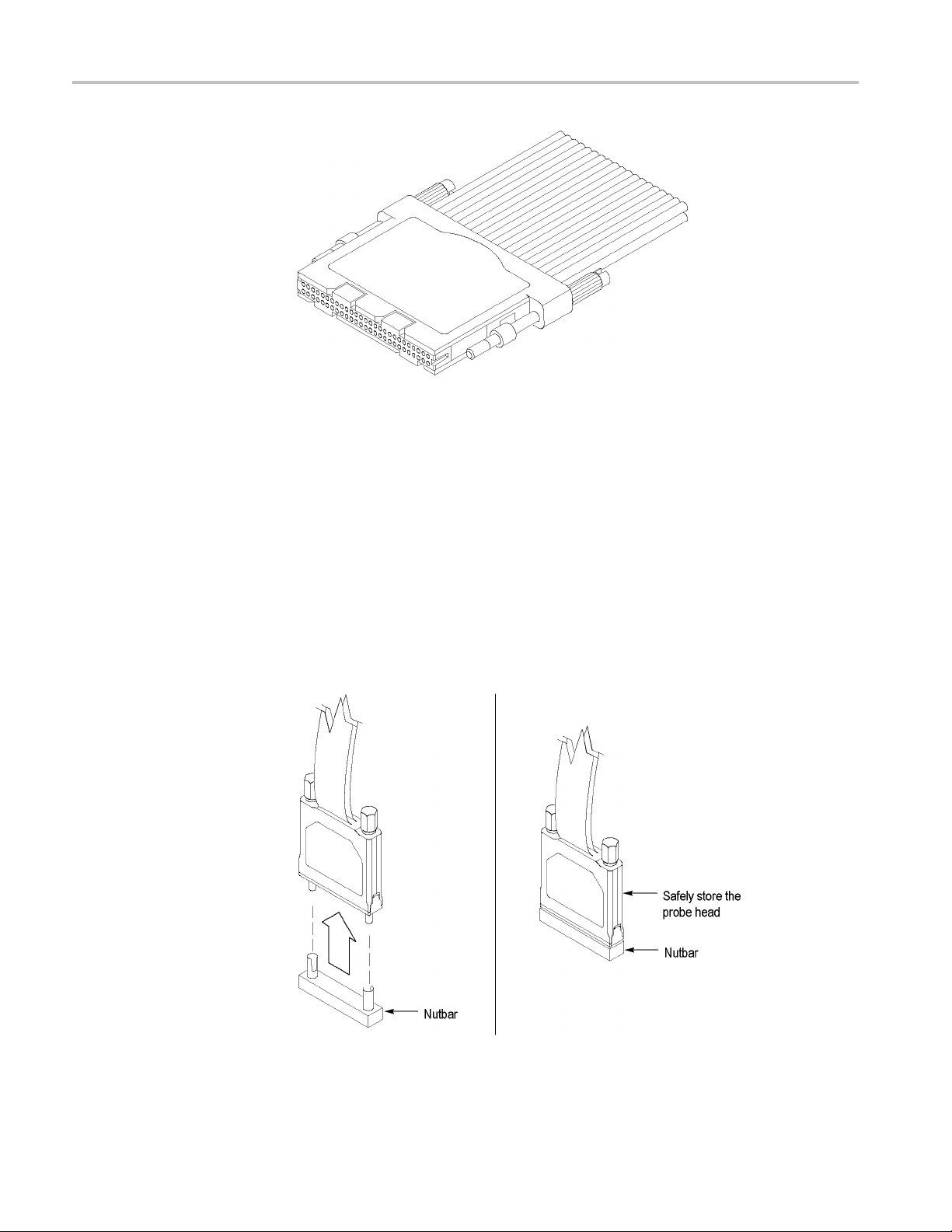
Storing the P6800 Probe Heads
To protect the elastomer, it is important to properly store the probe heads when the
probes a
renotinuse. (SeeFigure9.)
1. Locate the keying pin on the probe end and align it to the keying pin hole
on the n
2. While holding the probe end at a perpendicular angle to the nutbar,
finger
torque).
utbar.
-tighten both probe head screws until snug (no more than 1 in-lbs of
Figure 9: Storing the probe head
20 TLA7ACx Logic Analyzer Module Service Manual
Page 37

Maintenance
Storing the P6
900 Probe Heads
To protect the probe head, when the probes are not in use place the probe head
cover on the probe. (See Figure 10.)
1. Gently slide the probe cover over the probe end.
Figure 1 0: Storing the P6900 probe heads
TLA7ACx Logic Analyzer Module Service Manual 21
Page 38

Maintenance
22 TLA7ACx Logic Analyzer Module Service Manual
Page 39

Removal and Installation Procedures
This section describes how to remove and install the m ajor mechanical and
electrical modules. The procedures in this section assume that you already have
removed the module from the mainframe.
WAR N ING. Before doing any procedures in this manual, read the General Safety
Summary and
To prevent possible injury to service personnel or damage to electrical
components, read Preventing Electrostatic Discharge. (See page 13.)
Service Safety Summary located at the beginning of this manual.
Tools Requ
ired
Torque Requirements
The following table lists the tools needed to replace the internal components
of the logic analyzer module.
Table 3:
Name Descrip
Screwd
1/4-in
9/16-
Needle-nose pliers
Tighten all T-9 and T-10 screws to 4 in. lbs. Tighten standoff posts to 8 in. lbs.
Tools required for circuit board replacement
riverwithaT-9andaT-10Torxtip
ch nut driver
inch nut driver
Standa
Standa
Stand
Stan
tion
rd tool
rd tool
ard tool
dard tool
TLA7ACx Logic Analyzer Module Service Manual 23
Page 40

Removal and Installation Procedures
Injector/Eje
ctor Handles
Removal
You will need a screwdriver with a T-10 tip to complete the following procedures.
Use the following procedure to remove the injector/ejector handles:
1. Place the module on the right side. (See Figure 11.)
2. Remove the two screws that secure the injector/ejector handle to the chassis.
3. Remove the
injector/ejector handle from the module.
Figure 11: Injector/ejector handle replacement
24 TLA7ACx Logic Analyzer Module Service Manual
Page 41

Removal and Installation Procedures
Covers
Installation
Removal
Use the followi
figure. (See Figure 11.)
NOTE. The top and bottom injector/ejector handles are not interchangeable. The
top injector/ejector handle assembly hasanotchonrightsideandatabontheleft
side; the bottom injector/ejector handle assembly does not have a notch or a tab.
1. Install the injector/ejector handle through the front panel c utout onto the
mounting post.
2. Install the screws to secure the injector/ejector handle to the chassis.
3. Apply the proper replacement label (see the Replaceable Mechanical Parts
List for label part numbers if necessary).
You will need a screwdriver with a T-9 and a T-10 tip to complete the following
procedures.
Use the following procedure and figures to remove the covers:
ng procedure to install the injector/ejector handles by referring the
1. Place the module on the right side. (See Figure 12.)
2. Remo
3. Rem
4. Removethetwotopscrewsandthetwobottomscrewsthatsecurethecover
5. If you have a 102-channel module or a 136-channel module with a merge
6. Slide the cover back to disengage the tab and lift the cover from the chassis.
ve the two screws on the rear of the chassis and the two rear screws,
located on either side of the rear panel, that secure the rear panel to the chassis.
ove the rear panel and set it aside.
the chassis.
to
ble, complete to following steps. (See Figure 13.)
ca
a. Remove the eight T-9 countersunk screws holding the bracket to the cover.
b. Lift the assembly out of the cover and then reach into the hole and
disconnect the merge cable from the circuit board.
TLA7ACx Logic Analyzer Module Service Manual 25
Page 42

Removal and Installation Procedures
Figure 12: Cover removal
26 TLA7ACx Logic Analyzer Module Service Manual
Page 43

Removal and Installation Procedures
ure 13: Removing the merge cable bracket from the cover
Fig
TLA7ACx Logic Analyzer Module Service Manual 27
Page 44

Removal and Installation Procedures
Installation
Use the followi
NOTE. Install the cover tightly against the chassis. This will ensure that the
module fits into adjacent slots in the mainframe.
1. Place the module on its right side. (See Figure 12.)
CAUTION. To prevent damage to the module during the installation process,
reinstall the cover exactly as described in steps 2 through 8.
If the cover is not properly seated, the module can be damaged when you install
it in a mainframe.
2. Insert the cover at an angle (step 1) such that the front edge of the cover
engages with the EMI gaskets on the back of the front panel. Then push the
rear of the cover in place (step 2). (See Figure 14.)
ng procedure and figures to install the covers:
Figure 14: Installing the cover onto the chassis
3. Make sure that the cover is fully seated (no gaps) against the front and rear
chassis flanges. (See Figure 15.)
4. While holding the cover in place, install the four T-10 Torx-drive screws
nearest the front of the module (two on each side of the cover), to secure the
cover to the chassis.
5. Slide the rear panel on the chassis and install the two rear panel T-10
Torx-drive screws.
6. Gently squeeze the chassis flange and rear panels flange together while
tightening the screws on the sides. This ensures that the rea r panel does not
28 TLA7ACx Logic Analyzer Module Service Manual
Page 45

Removal and Installation Procedures
rotate, otherw
mainframe.
7. Install the tw
module (one on each side of the cover).
8. Place the co
9. If your instrument has a merge cable, complete the following steps to install
the merge ca
a. Feed the merge cable through the cover.
b. Carefully connect the merge cable to the circuit board. (See Figure 13.)
c. Insert the bracket assembly into the hole in the cover.
d. Install the eight T-9 countersunk screws on the bracket.
10. Check and tighten all screws to 4 in lbs.
ise the module may not seat properly when installed in the
o remaining T-10 Torx-drive screws nearest the rear of the
ver onto the chassis.
ble assembly:
TLA7ACx Logic Analyzer Module Service Manual 29
Page 46

Removal and Installation Procedures
Figure 1 5: Seating the cover on the chassis
Local Processor Unit Board
ill need a screwdriver with a T-10 tip to complete the following procedures.
You w
NOTE. When placing an order for a replacement LPU board or an LPU exchange
board from the Tektronix Exchange Center, you must supply the model number,
serial number, PowerFlex Option upgrade number and firmware level.
30 TLA7ACx Logic Analyzer Module Service Manual
Page 47

Removal and Installation Procedures
Removal
Use the followi
1. Perform the Covers removal procedure. (See page 31.)
2. Remove the five T-10 Torx-drive screws that secure the LPU board to the
chassis.
CAUTION. Ha
extension.
3. Carefully lift the LPU board up from the chassis to disengage the 160-pin
connecter from the acquisition board.
4. Move the LPU board away from the front panel until the tabs clear the front
subpanel and then remove the LPU board from the chassis. (See Figure 16.)
ng procedure and figure to remove the LPU board:
ndle the LPU board gently to avoid breaking the front panel LED
Figure 16: LPU board removal
TLA7ACx Logic Analyzer Module Service Manual 31
Page 48

Removal and Installation Procedures
Installation
Use the followi
1. Place the LPU board (component side down) over the chassis and insert the
tabs on the LPU
2. Line up the pins on the 160-pin connector from the LPU board to the
acquisitio
3. Install the five T-10 Torx-drive screws that secure the LPU board to the
chassis.
4. Perform the Covers installation procedure. (See page 28.)
NOTE. Aft
level. The PowerFlex configuration information is listed on the side panel of
the logic analyzer module. This information should match the module specific
information on the System Properties tab in the TLA application.
If the PowerFlex level does not match the information on the side panel label, you
must return the entire logic analyzer module to your local Tektronix service center.
ng procedure a nd figure to install the LPU board:
board into the front subpanel as shown in following figure.
n board and gently press the LPU board in place.
er replacing the LPU board, you must verify the proper PowerFlex
igure 17: Inserting LPU board tabs into front subpanel
F
32 TLA7ACx Logic Analyzer Module Service Manual
Page 49
Acquisition Board
Removal and Installation Procedures
You will need a1/4inch nut driver in addition to the T-10 Torx tip screwdriver
to complete the following procedures.
Removal
Use the following procedure to remove the acquisition board by referring the
figure. (See Figure 20.)
1. Perform the Covers removal procedure. (See page 25.)
2. Perform th
NOTE. The 34-channel and 68-channel modules do not have a left side or right
side merge cable. For these modules, ignore the steps dealing with the merge
cable.
3. Complete the following steps and figures to remove the merge cable assembly.
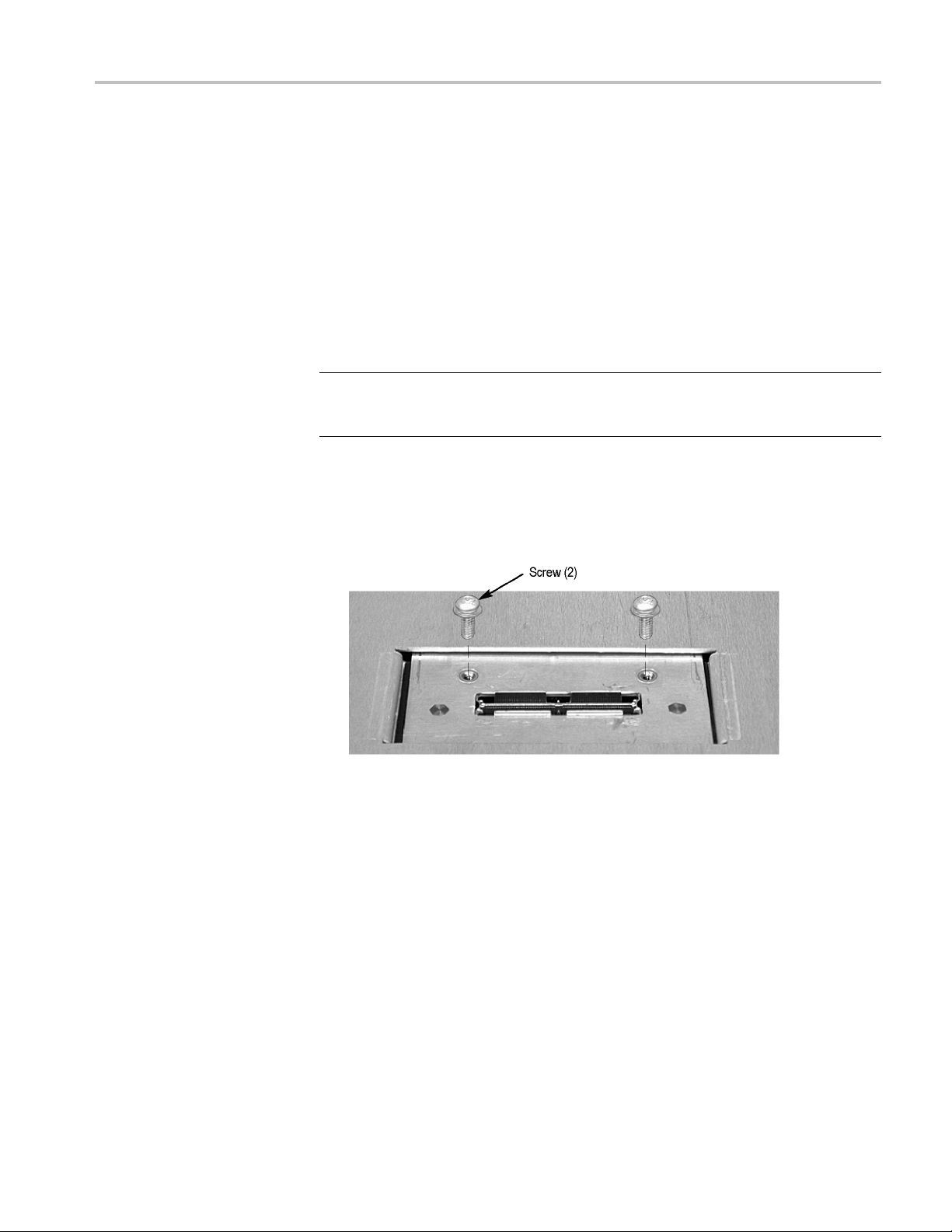
a. Turn the chassis over and remove the two T-10 screws from the merge
cable assembly bracket as shown in the following figure.
e Local Processor Unit Board removal procedure. (See page 31.)
Figure 18: Remove the single screw from the merge cable bracket
b. Carefully slide the bracket back underneath the cover until you can grasp
theedgeasshowninthefollowingfigure.
c. Lift the merge cable assembly bracket out of the hole being careful not to
damage the assembly.
d. Disconnect the merge cable from the acquisition board and set the
assembly aside.
TLA7ACx Logic Analyzer Module Service Manual 33
Page 50

Removal and Installation Procedures
Figure 19: Removing the merge cable assembly
1
4. Turn the chassis over and then remove the five spacer posts with the
/4nut
driver from the acquisition board.
5. Disconnect the four analog output cables on the acquisition board.
34 TLA7ACx Logic Analyzer Module Service Manual
Page 51

Removal and Installation Procedures
6. Remove the five T
front of the chassis.
-10 screws from the acquisition board located near the
Figure 20: Removing the acquisition board from the chassis
7. Carefully slide the acquisition board away from the front panel until the probe
connectors clear the front panel. Then lift the circuit board out of the chassis.
TLA7ACx Logic Analyzer Module Service Manual 35
Page 52

Removal and Installation Procedures
Installation
Use the followi
1. Place the acquisition board into the chassis.
2. Carefully slide the acquisition board into the chassis until the probe connectors
fit snuggly into the front panel slots.
3. Install five T-10 screws on the acquisition board at the front of the chassis.
4. Install the five spacer posts that secure the acquisition board to the chassis.
5. Connect the four analog output cables from the front panel to the acquisition
board.
6. Complete the following steps to install the merge cable assembly (skip these
steps if your instrument does not have a merge cable assembly):
a. Turn the chassis over.
b. Feed the merge cable into the hole and connect it to the circuit board.
(See Figure 19.)
c. Carefully slide the merge cable assembly into the hole.
d. Slide
bracket in place.
ng procedure to install the acquisition board:
the bracket forward and install the tow T-10 screws to hold the
7. Perfo
8. Perform the Covers installation procedure. (See page 32.)
rm the Local Processor Unit Board installation procedure. (See page 32.)
36 TLA7ACx Logic Analyzer Module Service Manual
Page 53

Removal and Installation Procedures
Front and Rear
Removal
EMI Gaskets
Use the following procedure to remove the front and rear EMI gaskets:
1. Perform the Cover removal procedure. (See page 33.)
2. For the front EMI gaskets:
a. Locate the gasket to be replaced.
b. Lift the ga
3. For the two rear gaskets on the chassis:
a. Perform the Local Processor Unit Board removal procedure. (See
b. Perform the Acquisition Board removal procedure. (See page 33.)
c. Lift the gasket fingers and rotate the gasket off. (See Figure 21.)
sket fingers and rotate the gasket off.
page 31.)
gure 21: Rear EMI gasket removal
Fi
TLA7ACx Logic Analyzer Module Service Manual 37
Page 54

Removal and Installation Procedures
Installation
Use the followi
1. Position each gasket so the gasket fingers face the outside of the module.
CAUTION. To a
2. Pick up each gasket at the end whe re the gasket finger is formed up. Then
rotate the gasket on. As you do this, lift up any fingers that bind to the chassis
or cover.
3. Slide each gasket gently from s ide to side to ensure that the gasket snaps
in place.
ng procedure and figure to install the EMI gaskets:
void breaking the gasket fingers, do not lift the fingers too high.
Side EMI Gaskets
Figure 22: Rear EMI gasket replacement
4. Reinstall the Acquisition board if you removed them to install the rear EMI
gaskets. (Se
5. Reinstall the LPU board if you removed them to install the rear EMI gaskets.
(See page 32.)
6. Install the module covers. (See page 32.)
To remove the side EMI gaskets, remove the covers and circuit boards as necessary
to access
To install the side EMI gaskets , pop them into place on the covers.
the EMI gaskets. (See Figure 24.) Pop the EMI gaskets out of the cover.
epage36.)
38 TLA7ACx Logic Analyzer Module Service Manual
Page 55
Troubleshooting
WAR N ING. Before performing this or any other procedure in this manual, read the
General Safety Summary and Service Safety Summary located in the Tektronix
Logic Analyzer Family Product Safety & Compliance Instructions (Tektronix part
number 071-2
components, read Preventing Electrostatic Discharge. (See page 13.)
591-xx). Also, to prevent possible injury or damage to electrical
Service Level
This secti
within the logic analyzer module. The process is as follows:
1. Review Ch
2. Perform
3. Perform the Troubleshoot the Logic Analyzer Module procedure to identify
If you replace a faulty circuit board or assembly found using these procedures,
you must follow any verification and adjustment procedures identified in Table
5-6 for the replaced board. (See Table 6.)
This section supports isolation of faults within the logic analyzer module to the
replaceable-part level that’s reflected in the replaceable parts lists in Mechanical
Parts List section. (See page 53.) In most cases, faults are isolated to circuit boards
assemblies, but not to individual components on those boards. (See page xi.)
or
on contains information and procedures designed to help isolate faults to
eck for Common Problems to eliminate easy to find problems.
(See page 40.)
procedures outlined in Eliminate Other Problem Sources to eliminate
the mainframe, probes, and other modules as the source of the fault(s). (See
page 41.)
the failed replaceable part within the module. (See page 43.)
Fault isolation is supported to the following circuit boards and replaceable parts:
LPU board
Acquisition board
TLA7ACx Logic Analyzer Module Service Manual 39
Page 56

Troubleshooting
Required Documentation
You may need to refer to the additional service manuals to isolate faults. In
addition, other manuals and other sections in this manual contain instructions you
will need to complete repairs after locating a faulty part. For a list of supplemental
documentation, refer to the following table.
Manual or Section Purpose
TLA7000 Series Mainframe Service Manual To eliminate benchtop or portable mainframe
TLA7000 Series Logic Analyzer Installation
Manual
TLA7KUP Mainframe Field Upgrade
Instruction Manual
Check for Common Problems
as problem source (whichever configuration
is in use)
To remove and reinstall modules in
mainframe
To reinstall the TLA application software
Use the following table to quickly isolate possible failures. The table lists
problems related to the logic analyzer module and possible ca uses. The list is not
exhaustive, but it may help you eliminate problems that are easy to fix.
CAUTION. To avoid damaging the logic an
alyzer module or the mainframe, be
sure to power down the mainframe before removing or reinstalling any modules.
Table 4: Failure symptoms and possibl
Symptom Possible cause(s)
Mainframe does not power on Power connection faulty; check or substitute power cord
Mainframe does not boot
Modules not recognized
ecauses
Fuse blown; check line fuse
Mainframe power supply failure; contact local Tektronix service center
Mainframe controller is not installed properly (or not at all)
Non-system disk or floppy in external drive; make sure logic analyzer boots from hard drive
(Refer to the TLA7000 Series Logic Analyzer Installation Manual for software reinstallation
procedures)
Hard drive failure or corrupted
Modules not fully inserted; mak
files on hard drive; contact local Tektronix service center
e sure front of module is flush with front panel
Mainframe power supply failur
Corrupted module firmware; rei
Upgrade Instruction Manual for information on reinstalling the latest firmware
Module logical address switches set to 00. Reset the switches to FF
e; contact local Tektronix service center
nstall firmware. Refer to the TLA7KUP Mainframe Field
40 TLA7ACx Logic Analyzer Module Service Manual
Page 57

Table 4: Failure symptoms and possible causes (cont.)
Symptom Possible cause(s)
Controller does not power on Module not fully i nserted; make sure front of module is flush with front panel
Module failure; try substituting a known-good controller module and if necessary, contact
local Tektronix service center
Module does not pass the normal
power on diagnostics (READY
indicator not green)
Module loses settings when power
is turned off
Module will not acquire data or the
acquired data is incorrect
Module not fully i nserted; make sure front of module is flush with front panel
Module failure; see Troubleshoot the Logic Analyzer Module, or contact local Tektronix
service center
Open fuses on logic analyzer module circuit boards
Module failure; see Troubleshoot the Logic Analyzer Module, or contact local Tektronix
service center
NV RAM failure; refer to the Local Processor Unit Board for LPU board replacement
instructions. (See page 30.)
Module failure; see Troubleshoot the Logic Analyzer Module, or contact local Tektronix
service center
Faulty probe, leadset, or probe adaptor
Troubleshooting
Eliminate Other Problem Sources
The logic analyzer module is part of the Tektronix Logic Analyzer Family, which
ists of modules installed in either a benchtop or portable mainframe. The
cons
following procedures will help you eliminate the mainframe and other modules as
possible sources of failures.
TLA7ACx Logic Analyzer Module Service Manual 41
Page 58

Troubleshooting
Substitute a Good Module
If you have avai
procedure:
1. Remove the sus
2. Install a known-good logic analyzer module in the same slot as the suspected
module (ver
addressasthemodulethatyouarereplacing).
3. Power-on th
4. If the failure symptoms are still present with the known-good logic analyzer
module ins
attached probes, not in the logic analyzer module.
5. To elimin
are properly connected to the target system.
NOTE. Viewing the diagnostic window from the TLA application may help you
isolate failures to individual modules or to the mainframe.
6. If the logic analyzer operates normally with the known-good logic analyzer
module and with known-good probes, the suspect logic analyzer module
needs to be repaired. For additional troubleshooting procedures, refer to the
Troubleshoot the Logic Analyzer Module. (Seepage43.)
lable a known-good logic analyzer module, perform the following
pect logic analyzer module from the mainframe.
ify that address switches on the rear of the module are set to same
e logic analyzer and check for normal operation.
talled, the problem most likely is in the mainframe or in the
ate the probes, use known-good probes and verify that the probes
e-Level
Prob
Troubleshooting
If the logic analyzer module acquires no data or faulty data, the probes may be
at fault. Perform the following procedure to isolate faults to a probe or to the
logic analyzer module.
TE. The procedure below requires that the logic analyzer is functional and
NO
operates normally when the modules are installed.
42 TLA7ACx Logic Analyzer Module Service Manual
Page 59

Troubleshooting
1. Verify that the
system.
2. Move the suspected probe to another probe connector and observe if the
problem follows the probe. If the problem does not follow the probe, the
module may be faulty.
3. Substitute the suspected probe with a known good probe and observe if the
problem is still present. If the problem still occurs, the module may be faulty.
To isolate the problems within that module, refer to the Troubleshoot the
Logic Analyzer Module. (Seepage43.)
4. If you are using a general purpose probe with lead sets and you have
determined that the p robe is faulty, try to isolate the problem to an individual
channel. A faulty channel may ind
podlets by switching single podlets and observing if the problem tracks with
the suspected podlet.
probe is correctly connected to the module and to the target
Troubleshoot the Logic Analyzer Module
Follow the procedure in this section to identify the failed part within the logic
analyzer module.
This procedure requires that the module is installed in a fully functional
mainframe. If you have not determined that the mainframe is functional, or if
you suspect the problem might be in a probe or in another module, refer to the
Eliminate Other Problem Sources. (Seepage41.)
icate a faulty probe podlet. Isolate faulty
Equipment Required
Preparation
Calibration and Diagnostic
Procedures
The basic troubleshooting procedures require minimal test equipment. There are
no accessible test points to measure voltages. An ohmmeter is recommended
for checking fuses.
The fault isolation procedure requires that you:
ecognize codes flashed by the front-panel LEDs during power up
R
Are familiar with the power-on diagnostics
To fill these requirements, read the topics below before performing the Fault
Isolation Procedure. (See page 45.)
The following calibration and diagnostic procedures will help you diagnose
problems.
Self Calibration. Use self calibration to calibrate the installed modules. Run the
self calibration after a minimum of a 30 minute warm-up and prior to running the
extended diagnostics.
TLA7ACx Logic Analyzer Module Service Manual 43
Page 60
Troubleshooting
Power-On Diagn
logic analyzer at every power on. If any failures occur at power on, the screen
displays the calibration and diagnostics property sheet.
If there are no diagnostic failures when you power on the logic analyzer, you
can display and run the calibration and diagnostics property sheet by selecting
Calibration and Diagnostics from the System menu.
Extended Diagnostics.
The extended diagnostics execute more thorough tests than the power-on
diagnostics. Using the extended diagnostics, you can d o the following tasks:
Run tests individually or as a group
Run tests once or continuously
Run tests until failures occur
NOTE. Certain diagnostic tests will fail if probes are attached. For best results,
run the diagnostics with probes disconnected from the module.
To run t he extended diagnostics, do the following steps:
ostics. Power-on diagnostics check basic functionality of the
1. Disconnect the probes from the logic analyzer module.
2. Star
3. From the System menu, select Calibration and Diagnostics.
4. Select the Extended Diagnostics p roperty page.
5. Select the individual tests, group of tests, or all tests.
6. Click the Run button.
While the tests are executing, the word Running displays adjacent to the tests.
When the tests are complete, either a Pass or Fail indication displays adjacent
to each test.
Merged Modules. The extended diagnostics include a special merge test that
verifies the correct pipeline adjustment for the master module, inside slave
module, and outside slave module. This test does not require the modules to
be physically merged together.
Every time modules are merged in the System Configuration window, a calibration
is performed between the merged modules. An error message will appear if there
are any problems with the merge cables, circuit board traces, or if the calibration
fails.
t the TLA application if it is not already running.
44 TLA7ACx Logic Analyzer Module Service Manual
Page 61

Troubleshooting
Fault I solation Procedure
The Primary Tro
logic analyzer module. (See Figure 23.) Use the following procedure with that
tree:
To determine if module is recognized, perform the following steps:
1. Install the
2. Before you power on the mainframe, look at the READY, ACCESSED
ARM’D, and T
3. Power on the mainframe and note how the front panel indicators respond.
a. Verify that the green READY indicator turns on while the diagnostics
are being checked. If the green READY indicator does not turn on, the
module is
the LPU board.
b. Verify t
indicator stays on while the module is accessed by the controller. After
the System window displays, the indicator blinks anytime the controller
accesses the module.
4. If steps a and b are verified, the module is recognized; if not verified, the
module is not recognized. Proceed as the troubleshooting tree instructs.
ubleshooting Tree provides troubleshooting steps that test the
logic analyzer module into a known-good mainframe.
RIG’D front panel indicators.
not being recognized which indicates possible problems on
hat after a few seconds the ACCESSED indicator turns on. The
5. If diagnostic failures occur, replace the circuit board indicated by the
troubleshooting tree. For further confirmation, you can correlate the failed test
displayed with a board using the following table. (See Table 5.) You should
also first check the "special cases" of diagnostic failures below:
Note from the tree, that if all the diagnostics pass, but self calibration
fails, replace the Acquisition board.
If any of the Kernel test groups fail (ROM check, LPU RAM, LPU
Address decode, etc.) replace the LPU board.
If the kernel group passes, but there are other failures, replace the
Acquisition board. Also, ensure that the probes are disconnected from the
module before running the diagnostics.
If multiple tests fail, the problem could be power-supply related problems
or the mainframe. If replacing the acquisition board does not remedy the
failures, try replacing the LPU board.
NOTE. Due to the module design, there are no accessible test points on the
module to connect external test equipment, to help isolate faults to an individual
circuit board.
6. Use the Removal and Installation Procedures to replace the faulty circuit
board. (Seepage23.)
TLA7ACx Logic Analyzer Module Service Manual 45
Page 62

Troubleshooting
Primary Troubleshooting
Chart
7. Refer to the Tab
and adjustment procedures identified for the replaced module. (See Table 6.)
le 5-6 after module replacement and perform all verifica tion
Figure 23: Primary troubleshooting chart
46 TLA7ACx Logic Analyzer Module Service Manual
Page 63

Troubleshooting
Diagnostics Table
The following t
able can help you isolate problems to one of the circuit boards in
themodule(usetheRemoval and Installation Procedures to replace the faulty
circuit board). (See page 23.)
Table 5: Diagnostic tests
Circuit board Group Test Power on Extended
LPU board Kernel
Acquisition
board
Timestamp
Acquisition
Data Path
Trigger
Acquisition
RAM
ROM Check
LPU RAM
Address Decode
NVRAM Check
Timestamp Rollover
Acquisition RAM Data Bus
Acquisition RAM Address Bus
Timestamp Acquire
Qualifier/Combiner RAMClock
Clock State Machine RAM
Address/Data Bus
MagniVu RAM
Internal RAM
Trigger Crossbar
Signal/Trigger Lines
Trigger State Machine Counters
Prefill Counter
Word Recognizer
Transition Detector
Clock Group Detector
At-speed Transition Detect
Snapshot
RAM Select
Acquisition Memory
TLA7ACx Logic Analyzer Module Service Manual 47
Page 64

Troubleshooting
Table 5: Diagnostic tests (cont.)
Circuit board Group Test Power on Extended
Acquisition
board
Miscellaneous
Test s
Memory
Interface
Controller
Miscellaneous
2Tests
Acquisition Address Decode
Threshold
At-speed Async Acquire
Pseudo Random
SFDL-1
SFDL-2
PLL
Demux
Edge Detector
Setup and Hold
Glitch
AD B us
MAR Rollover
Waveform 0
Waveform 1
Waveform Pins
Waveform Change
Search Stack
Internal Search
External Search
Counters
RAM Data
RAM Address
High-Speed Memory Compare
Pattern Acquire
Counters
Timers
Store Stretch
Range Recognizer
Global Storage
CSM Input Path
48 TLA7ACx Logic Analyzer Module Service Manual
Page 65

Troubleshooting
Adjustment Af
ter Repair
After replacing a circuit board or assembly due to electrical failure, locate the
board removed in the following table and perform the indicated procedures.
Table 6: Requirements after replacement
Board replaced Adjustment required Verification checks
LPU board Adjustment: PowerFlex1,
Firmware leve l restoration
Deskew, Self Calibration,
Threshold tests
Acquisition board
1
The PowerFlex restoration or changes can only be made by Tektronix service p ersonnel.
2
Refer to the TLA7KUP Mainframe Field Upgrade Instruction Manual for instructions for updating module firmware.
Adjustment: Self Calibration,
Deskew, Threshold tests
Updating or Restoring the Logic Analyzer Firmware
You may have to update the firmware on the logic analyzer module if the module
does not appear in the TLA System window after you have serviced the module
or after you have updated the TLA application software on the mainframe. You
can update multiple modules and module types during a single firmware update
session. The most current firmware resides on a file on the hard disk of the logic
analyzer mainframe.
2
Self Calibration, Power-on and
,
Extended Diagnostics, performance
verification procedures
Self Calibration, Power-on and
Extended Diagnostics, performance
verification procedures
1. Note which of the modules that may require new firmware.
If any modules are missing from the System window, you can verify the status
of the modules by doing the following steps:
Select System Properties from the System menu.
Click the Modules tab.
Note the information under the Messages column for any installed
modules. If any modules indicate invalid or similar m essages, you must
update the firmware for those modules.
2. Disconnect any probes connected to the modules that you want to update.
3. Exit the logic analyzer application.
4. Click Start > Programs > Tektronix Logic Analyzer > TLA Firmware Loader.
5. When you see the pop-up prompting you to cycle the power on the mainframe
after completing the upgrade operation, click Yes.
The logic analyzer will scan the mainframe to determine which modules are
installed and which modules can have their firmware upgraded. If you have
any o lder modules, you may see them listed in the bottom half of the window.
TLA7ACx Logic Analyzer Module Service Manual 49
Page 66

Troubleshooting
These modules c
rear of the modules.
6. Select the mod
in the Supported list box near the top of the window. If you are updating
more than one module at a time, note the slot location of the module in the
selection box.
7. Select Load Firmware from the Execute menu.
8. Click the “TLA7AXX.lod file.”
NOTE. Be sure to select the proper .lod file for each module. Note the slot number
in the title bar so that you select the correct module for the .lod file.
9. Click OK. You will be asked to confirm your action; click Yes when prompted.
NOTE. The program will not allow you to load firmware to an incompatible
module. For example, the program will not load DSO firmwaretoalogicanalyzer
module.
The program will load the firmware for each module one at a time. The
process may take several minutes per module.
annot be updated until you install the flashjumperonthe
ules that you want to update from the list of modules displayed
10. Exit the firmware loader program and power down the logic analyzer. You
must power down the logic analyzer to allow the TLA application to start
up properly.
11. Remove the logic analyzer module from the mainframe.
12. Locate the big label on the side of the module.
cord the firmware version that is printed on the label. You will need this
13.Re
information to see that the firmware version matches the label.
einstall the module in the mainframe and power on the mainframe.
14.R
15. After the logic analyzer completes the power-on diagnostics, select System
Properties from the System me nu.
16. Click the module tab (for example, LA1).
17. Verify that the firmware version for the selected module matches the version
on the label that you recorded in step 13.
18. If the firmware versions do not match, power down the mainframe, remove
the module from the mainframe and update the label.
50 TLA7ACx Logic Analyzer Module Service Manual
Page 67

Repackaging Instructions
This section contains the information needed to repackage the logic analyzer
module for shipment or storage.
Packaging
If at all possible, use the original packaging to ship or store the instrument. If the
original packaging is not available, use a corrugated cardboard shipping carton
having a test strength of at least 275 pounds (125 kg) and with an inside dimension
at least si
cushioning material to prevent the instrument from moving around in the shipping
container. Seal the shipping carton with an industrial stapler or strapping tape.
Shipping to the Service Center
Contact the Servic e Center to get an RMA (return material authorization) number,
and any return or shipping information you may need.
If the instrument is being shipped to a Tektronix Service Center, enclose the
following information:
x inches (15.25 cm) greater than the instrument dimensions. Add
The RMA number.
The owner’s address.
and phone number of a contact person.
Name
Type of instrument and serial number.
Reason for returning.
A complete description of the service required.
NOTE. When ordering the LPU board for exchange or repair, you will need
to supply the above information, including the firmware level and PowerFlex
onfiguration information.
c
Mark the address of the Tektronix Service Center and the return address on the
shipping carton in two prominent locations.
CAUTION. When returning the LPU board separately, be sure to properly support
the narrow LED arm of the circuit board so it will not be damaged during transit
or storage.
TLA7ACx Logic Analyzer Module Service Manual 51
Page 68

Repackaging Instructions
Storage
The logic analyzer module should be stored in a clean, dry environment. The
following environmental characteristics apply for both shipping and storage:
Temperature range: -40 °F to +160 °F (-40 °C to +71 °C).
Altitude: To 40,000 feet (12,190 meters).
52 TLA7ACx Logic Analyzer Module Service Manual
Page 69

Parts List
This section contains a list of the replaceable parts for the Tektronix logic analyzer
module. Use this list to identify and order replacement parts, modules, and
subcomponents.
Parts Order
ing Information
Part Number Revision
Level
Replacement parts are available through your local Tektronix field office or
representative.
Changes to Tektronix products are sometimes made to accommodate improved
components as they become available and to give you the benefit of the latest
improvem
following information in your order:
If you order a part that has been replaced with a different or improved part, your
local Tektronix field office or representative will contact you concerning any
change in part number.
Tektronix part numbers contain two digits representing the revision level of the
part. For most parts in this manual, you will find the letters XX in place of the
revision level number.
ents. Therefore, when ordering parts, it is important to include the
Part num
Instrument type or model number
Instrument serial number
Instrument modification number, if applicable
ber
When you order parts, Tektronix will provide you with the most current part for
your product type, serial number, and modification (if applicable). At the time o f
your order, Tektronix will determine the part number revision level needed for
our product, based on the information that you provide.
y
TLA7ACx Logic Analyzer Module Service Manual 53
Page 70

Parts List
Using the Replaceable Parts List
This section contains a list of the mechanical and/or electrical components that
are replaceable for the logic analyze r module. Use this list to identify and order
replacement parts. The following table describes each column in the parts list.
Column Column name Description
1 Figure and i
number
2 Tektronix part
number
3 and 4
5
6 Name and
Serial number Column three indicates the serial number at which the part was first effective. Column four
Qty This indicates the quantity of parts used.
description
ndex
Items in this section are referenced by figure and index numbers to the exploded view
illustrations that follow.
Use this part number when ordering replacement parts from Tektronix.
s the serial number at which the part was discontinued. No entry indicates the part is
indicate
good for all serial numbers.
An item name is separated from the description by a colon (:). Because of space limitations,
an item name may sometimes appear as incomplete. Use the U.S. Federal Catalog handbook
r further item name identification.
H6-1 fo
Abbreviations
viations conform to American National Standard ANSI Y1.1-1972.
Abbre
54 TLA7ACx Logic Analyzer Module Service Manual
Page 71

Parts List
Figure 24: Logic analyzer module exploded view
Fig. index
number
24-1 671-5339-XX 1
-2
-3 200-4672-XX 1
-4 211-0409-XX 22
-5
Tektronix part
number
407-4859-XX 1
407-4860-XX 1
348-1537-XX 6
Serial no.
effective
Serial no.
discont’d Qty Name & description
CIRCUIT BD ASSY:MERGE CONNECTOR, LEFT SIDE, TESTED
BRACKET:MERGE, COVER, LEFT SIDE,0.050 AL
BRACKET:BLANK FLAT,MERGE, COVER, LEFT SIDE, 0.050 AL
COVER:TWO WIDE, 0.062 AL, TLA7000 SERIES,
SCR, ASSEM WSHR:4-40 X 0.312, PNH, STL, CDPL, T-10 TORX DR
GASKET, EMI:CLIP-ON, 1.98 L, BE CU, TIN PLATED, W/T LANCES
TLA7ACx Logic Analyzer Module Service Manual 55
Page 72

Parts List
Fig. index
number
-6
-7
-8 260-2597-X
-9
-10 671-5340
-11
-12 131-6643-XX 4
-13 386-6868-XX 1
-14 348-13
-15 441-2
-16 367-
-17
8
-1
9
-1
20
-
21
-
-22 174-4542-XX 4
Tektronix part
number
671-5312-XX 1
150-1278-XX 3
150-1279-XX 1
129-1478-XX
X
XX
671-6442-
671-6443-XX 1
671-6444-XX 1
-XX
-XX
407-4861
407-4862-XX 1
65-XX
258-XX
259-XX
441-2
2260-XX
441-
0484-XX
-0646-XX
335
-1163-XX
335
5-0639-XX
33
1-1315-XX
13
67-0483-XX
3
35-2074-XX
3
335-2075-XX 1
335-2076-XX 1
Serial no.
effective
Serial no.
discont’d Qty Name & descript
ion
CIRCUIT BD ASSY:LPU, LOCAL PROCESSOR UNIT
DIODE,OPTO:LED, GRN, 569NM, 2MCD AT 5V, 60 DEG VIEW ANGLE,
INTEGRAL RES, TINTED, DIFFUSED, RIGHT AN (NOT SHOWN)
DIODE,OPTO:LED, YELLOW, 585NM, 2MCD AT 5V, 60 DEG VIEW
ANGLE, INTEGRAL RES, TINTED DIFFUSED, RIGHT (NOT SHOWN)
5
2
1
1
1
2
1
1
1
1
1
1
1
4
1
1
SPACER, POST:1.738 L, 1.113 SPACING, W/ 0.35 L, 0.25 HEX, W/ 4-40
INT THD X 6-32 EXTERNAL THD, NIC
SWITCH,ROTARY:HEXADECIMAL, 100MA AT 50VDC, RIGHT ANGLE,
0.430 W X 0.400 H X 0.202 L
CIRCUIT BD ASSY:68 CH, 128MB, ACQUISITION, TLA7AC2
CIRCUIT BD
CIRCUIT BD ASSY:136 CH, 128MB, ACQUISITION, TLA7AC4
CIRCUIT BD ASSY:MERGE CONNECTOR, RIGHT SIDE, TESTED,
TLA7AA3, TLA7AA4, TLA7AB4, TLA7NA3, TLA7NA4
BRACKET:MERGE,CHASSIS, RIGHT SIDE, 0.062 AL
BRACKET
CONTACT, ELEC:GROUNDING, 0.169 L, 0.320 DEEP, ELECTROLESS
NICKEL
PANEL, VXI:VXI APPLICATION, TWO-WIDE, BACK PANEL
SHLD GSKT, ELEC:SYMETRICAL SLOTTED FINGER, 0.350 W X 7.5 L,
RIVIT MTG, SNAP-IN, RIVIT SPACING 1.5 IN
CHASSIS ASSY:68 CH, W/SUB FRONT PANEL LEXAN, 0.62 AL,
TLA7AC2
CHASSIS ASSY:102 CH, W/SUB FRONT PANEL LEXAN, 0.62 AL,
TLA7AC3
CHASSIS ASSY:136 CH, W/SUB FRONT PANEL LEXAN, 0.62 AL,
TLA7AC4
HANDLE,EJECTOR:INJECTOR/EJECTOR ASSEMBLY, TWO WIDE VXI,
W/OUT KEYING, SPRING LOADED, PLASTIC, 20% GL
MARKER, IDENT:LABEL, MKD FOR USE WITH TLA7000 SERIES,
BOTTOM INJECTOR/EJECTOR, 0.745 X 0.520, 0.010
MARKER, IDENT:LABEL, MKD FOR USE WITH TLA7000 SERIES,
BOTTOM INJECTOR/EJECTOR, 0.745 X 0.520, 0.010
MARKER, IDENT:CONFIGURATION LABEL, MKD TIMING, STATE
SPEED, RAM DEPTH, 0.475 X 0.975, 0.010 POLY, GE
CONN, RF JACK:BNC, PNL, 50 OHM, FEMALE, STR, PELTOLA/PNL
MNT, SILVER ALLOY, 0.576 MLG X 0.366 TERMN
HANDLE:INJECTOR/EJECTOR ASSEMBLY, TWO WIDE VXI,
W/KEYING, SPRING LOADED, PLASTIC, 20% GLASS-
LABEL, IDNTIFICATION, TLA7AC2
LABEL, IDNTIFICATION, TLA7AC3
LABEL, IDNTIFICATION, TLA7AC4
CA ASSY, RF:COAXIAL, 50 OHM, 8.0 L, MCX TO PELTOLA
ASSY:102 CH, 128MB, ACQUISITION, TLA7AC3
:BLANK FLAT, MERGE, CHASSIS, RIGHT SIDE, 0.062 AL
56 TLA7ACx Logic Analyzer Module Service Manual
Page 73

Parts List
Fig. index
number
-23
Tektronix part
number
211-04 86- XX 8
174-4595-XX 4
174-4596-XX 1
174-4597-XX 1
Serial no.
effective
Serial no.
discont’d Qty Name & descript
ion
SCREW, MACHINE:4-40 X 0.168 L, FLH, 100 DEG, TORX T-9
CABLE ASSY:BNC - BNC, 10X ATTENUATION, 50 OHM COAX
CABLE ASSY; ST
CABLE ASSY;RIBBON, EXTENDER CABLE FIXTURE, 28 AWG
STRANDED CAB
RANDED 7 INDIVIDUAL 16 AWG
LE 2 X 17, 0.1 INCH PITCH, CENTER POLARIZED
TLA7ACx Logic Analyzer Module Service Manual 57
 Loading...