

Page 1

Service Manual
TLA715
Dual Monitor Portable Mainframe
071-0913-00
This document applies to System Software version 4.1 and above.
Warning
The servicing instructions are for use by qualified
personnel only. To avoid personal injury, do not
perform any servicing unless you are qualified to
do so. Refer to all safety summaries prior to
performing service.
www.tektronix.com
Page 2

Copyright © Tektronix, Inc. All rights reserved. Licensed software products are owned by Tektronix or its suppliers and
are protected by United States copyright laws and international treaty provisions.
Use, duplication, or disclosure by the Government is subject to restrictions as set forth in subparagraph (c)(1)(ii) of the
Rights in Technical Data and Computer Software clause at DFARS 252.227-7013, or subparagraphs (c)(1) and (2) of the
Commercial Computer Software -- Restricted Rights clause at FAR 52.227-19, as appl icable.
Tektronix products are covered by U.S. and foreign patents, issued and pending. Information in this publication supercede s
that in all previously published material. Specifications and price change privileges reserve d.
Tektronix, Inc., P.O. Box 500, Beaverton, OR 97077
TEKTRONIX and TEK are registered trademarks of Tektronix, Inc.
Page 3

WARRANTY
Tektronix warrants that the products that it manufactures and sells will be free from de fects in materials and
workmanship for a period of one (1) year from the date of shipment. If a product proves defective during this
warranty period, Tektronix, at its option, either will repair the defective product without charge for parts and labor,
or will provide a replacement in exchange for the defective product.
In order to obtain service under this warranty, Customer must notify Tektronix of the defect before the expiration
of the warranty period and make suitable arrangements for the performa nce of service. Customer shall be
responsible for packaging and shipping the defective product to the service center designated by Tektronix, with
shipping charges prepaid. Tektronix shall pay for the return of the product to Customer if the shipment is to a
location within the country in which the Tektronix service center is located. Customer shall be responsible for
paying all shipping charges, duties, taxes, and any other charges for products returned to any other locations.
This warranty shall not apply to any defect, failure or damage caused by improper use or improper or inadequate
maintenance and care. Tektronix shall not be obligated to furnish service under this warranty a) to repair damage
resulting from attempts by personnel other than Tektronix representatives to install, repair or service the product;
b) to repair damage resulting from improper use or c onnection to incompatible equipment; c) to repair any
damage or malfunction caused by the use of non-Tektronix supplies; or d) to service a product that has been
modified or integrated with other products when the effect of such modification or integration increases the time
or difficulty of servicing the product.
THIS W ARRANTY IS GIVEN BY TEKTRONIX IN LIEU OF ANY OTHER WARRANTIES, EXPRESS
OR IMPLIED. TEKTRONIX AND ITS VENDORS DISCLAIM ANY IMPLIED WARRANTIES OF
MERCHANTABILITY OR FITNESS FOR A PARTICULAR PURPOSE. TEKTRONIX’
RESPONSIBILITY TO REPAIR OR REPLACE DEFECTIVE PRODUCTS IS THE SOLE AND
EXCLUSIVE REMEDY PROVIDED TO THE CUSTOMER FOR BREACH OF THIS WARRANTY.
TEKTRONIX AND ITS VENDORS WILL NOT BE LIABLE FOR ANY INDIRECT, SPECIAL,
INCIDENTAL, OR CONSEQUENTIAL DAMAGES IRRESPECTIVE OF WHETHER TEKTRONIX OR
THE VENDOR HAS ADVANCE NOTICE OF THE POSSIBILITY OF SUCH DAMAGES.
Page 4

Page 5

Table of Contents
Specifications
Operating Basics
General Safety Summary vii...................................
Service Safety Summary ix....................................
Preface xi...................................................
Manual Structure xi................................................
Manual Conventions xii..............................................
Related Manuals xii.................................................
Introduction xv..............................................
Adjustment and Certification Interval xv................................
Service Strategy xv.................................................
Service Offerings xvi................................................
Contacting Tektronix xvii.............................................
Product Description 1--1..............................................
Characteristics Tables 1--2.............................................
Installation 2--1.....................................................
Front Panel and Rear Panel Controls and Connections 2--3...................
Operating System and Application Interface 2--7...........................
Theory of Operation
Block Level Description 3--1....................................
Performance Verification
Performance Verification Procedures 4--1.........................
Summary Verification 4--1.............................................
Test Equipment 4--1..................................................
Functional Verification 4--3............................................
Portable Mainframe Certification 4--5...................................
Performance Verification Procedures 4--5.................................
Calibration Data Report 4--9....................................
Adjustment Procedures
Maintenance
Maintenance 6--1..............................................
Preparation 6--1.....................................................
Preventing ESD 6--1.................................................
Inspection and Cleaning 6--2...........................................
Removal and Installation Procedures 6--5.........................
Equipment Required 6--6..............................................
TLA715 Dual Monitor Portable Mainframe Service Manual
i
Page 6

Table of Contents
Removing the Replaceable Hard Disk Drive 6--7...........................
Accessories Pouch 6--8...............................................
Trim Ring 6--9......................................................
Flat Panel Display Assembly 6--10.......................................
Floppy Disk Drive 6--12...............................................
FixedHardDiskDrive 6--13............................................
Front Panel Interface Board 6--15........................................
Front Panel Control Assembly 6--15......................................
CD-ROM Drive 6--17.................................................
Trackball Assembly 6--18..............................................
Front Panel Control Board 6--19.........................................
Elastomeric Keypad 6--21..............................................
Card Guides 6--22....................................................
Bottom Cover and Feet 6--24............................................
Top Cover 6--25......................................................
Left Side Cover 6--27..................................................
Right Side Cover 6--27................................................
Power Supply 6--29...................................................
Rear Chassis Fan Tray 6--30............................................
Individual Fans 6--32..................................................
Cord Wrap Feet 6--34..................................................
Internal Components 6--35.............................................
Controller Board 6--37.................................................
Backplane Board 6--38................................................
Troubleshooting 6--41...........................................
Service Level 6--41...................................................
Check for Common Problems 6--42......................................
Eliminate Other Problem Sources 6--44...................................
Troubleshoot the Portable Mainframe 6--44................................
Power-On Diagnostics 6--46............................................
BIOS Setup Error Messages 6--51........................................
Update the BIOS Version 6--53..........................................
Adjustment After Repair 6--54..........................................
Startup Sequence 6--54................................................
Repackaging Instructions 6--57...................................
Packaging 6--57......................................................
Shipping to the Service Center 6--57......................................
Options
Electrical Parts List
Diagrams
Mechanical Parts List
ii
Tektronix Options 7--1................................................
Service Options 7--2..................................................
Parts Ordering Information 10--1.........................................
Using the Replaceable Parts List 10--2....................................
TLA715 Dual Monitor Portable Mainframe Service Manual
Page 7

List of Figures
Table of Contents
Figure 1--1: Front and side views 1--15.............................
Figure 2--1: Line fuse and power cord connector locations 2--2........
Figure 2--2: On/Standby switch location 2--2.......................
Figure 2--3: TLA715 Portable Mainframe front pan el 2--3............
Figure 2--4: Portable mainframe rear panel 2--5....................
Figure 3--1: TLA715 Portable Mainframe block diagram 3--1........
Figure 4--1: Calibration/certification procedure flow chart 4--2.......
Figure 4--2: Location of J1 and J2 pins in the portable mainframe 4--7.
Figure 6--1: Removing the replaceable hard disk drive 6--7...........
Figure 6--2: Removing the hard disk drive from the cartridge 6--8.....
Figure 6--3: Trim ring removal 6--9...............................
Figure 6--4: Flat panel display assembly removal 6--11................
Figure 6--5: Installing the fixed hard disk drive 6--14.................
Figure 6--6: Front-panel control assembly removal 6--16..............
Figure 6--7: Front panel control assembly parts locations 6--18.........
Figure 6--8: Front panel control assembly parts locations 6--20.........
Figure 6--9: Removing the card guide or the shutter assembly 6--22.....
Figure 6--10: Installing the card guide or shutter assembly 6--23.......
Figure 6--11: Flip stand and rear feet removal 6--24..................
Figure 6--12: Top and side cover removal 6--26......................
Figure 6--13: Removing the line cord from the right side cover 6--28....
Figure 6--14: Power supply removal 6--29...........................
Figure 6--15: Removing the handle and the panel from the
power supply 6--30..........................................
Figure 6--16: Rear chassis fan tray removal 6--31....................
Figure 6--17: Individual fan removal 6--33..........................
Figure 6--18: Cord-wrap feet removal 6--34.........................
Figure 6--19: Accessing the internal parts 6--36......................
Figure 6--20: Removing the controller board 6--38...................
Figure 6--21: Removing the backplane board 6--39...................
Figure 6--22: Primary troubleshooting tree 6--45.....................
TLA715 Dual Monitor Portable Mainframe Service Manual
iii
Page 8

Table of Contents
Figure 6--23: Jumper locations for bypassing front panel
control assembly 6--47.......................................
Figure 6--24: ResMan32 program output 6--50......................
Figure 6--25: Startup sequence 6--55...............................
Figure 9--1: TLA715 Portable Mainframe interconnection diagram 9--1
Figure 9--2: TLA715 Portable Mainframe block diagram 9--2........
Figure 10--1: External parts 10--7.................................
Figure 10--2: Front panel assembly 10--9...........................
Figure 10--3: Floppy disk drive, front panel interface board,
and related cables 10--11......................................
Figure 10--4: Controller board and EMI shield 10--13.................
Figure 10-- 5: Power supply and fan 10--15...........................
Figure 10--6: IView cables 10--16...................................
iv
TLA715 Dual Monitor Portable Mainframe Service Manual
Page 9

List of Tables
Table of Contents
Table i: Tektronix Logic Analyzer Family Documentation xiii.......
T able 1--1: Internal controller 1--2...............................
Table 1--2: Display system 1--4..................................
Table 1 --3: Backplane interface 1--5..............................
Table 1 --4: Latencies 1--7.......................................
Table 1--5: Front panel interface 1--10.............................
Table 1 --6: Rear panel interface 1--11..............................
Table 1 --7: AC power source 1--11................................
Table 1 --8: Secondary power 1--12................................
Table 1--9: Cooling 1--12........................................
Table 1--10: Certifications and compliances 1--13....................
Table 1 --11: Environmental 1 --14.................................
T able 1--12: Mechanical 1--15....................................
T able 2--1: TLA700 series line fuses 2--1..........................
Table 2--2: PC CardBus32 pin assignments 2--4....................
Table 2--3: USB (universal serial bus) pin assignments 2--4..........
Table 2--4: SVGA OUT pin assignments 2--6......................
Table 2 --5: Serial port pin assignments 2--6........................
Table 2 --6: LPT (parallel interface) pin assignments 2--7............
Table 4 --1: Test equipment 4--3..................................
Table 4--2: Functional verification procedures 4--3.................
T able 4--3: Performance verification procedures 4--5................
Table 4 --4: Power supply voltages and backplane connector pins 4--6..
Table 6 --1: Equipment required to service the portable mainframe 6--6.
Table 6--2: Failure symptoms and possible causes 6--42...............
Table 6--3: TLA Power-on diagnostic tests 6--46.....................
Table 6 --4: Command line options for ResMan32 6--48...............
Table 6 --5: BIOS error codes and explanations 6--51.................
Table 10--1: Parts lists column descriptions 10-- 2....................
TLA715 Dual Monitor Portable Mainframe Service Manual
v
Page 10

Table of Contents
vi
TLA715 Dual Monitor Portable Mainframe Service Manual
Page 11

General Safety Summary
Review the following safety precautions to avoid injury and prevent damage to
this product or any products connected to it. To avoid potential hazards, use this
product only as specified.
Only qualified personnel should perform service procedures.
While using this product, you may need to access other parts of the system. Read
the General Safety Summary in other system manuals for warnings and cautions
related to operating the system.
ToAvoidFireor
Personal Injury
Use Proper Power Cord. Use only the power cord specified for this product and
certified for the country of use.
Connect and Disconnect Properly. Do not connect or disconnect probes or test
leads while they are connected to a voltage source.
Ground the Product. This product is grounded through the grounding conductor
of the power cord. To avoid electric shock, the grounding conductor must be
connected to earth ground. Before making connections to the input or output
terminals of the product, ensure that the product is properly grounded.
Observe All Terminal Ratings. To avoid fire or shock hazard, observe all ratings
and markings on the product. Consult the product manual for further ratings
information before making connections to the product.
Do not apply a potential to any terminal, including the common terminal, that
exceeds the maximum rating of that terminal.
Do Not Operate Without Covers. Do not operate this product with covers or panels
removed.
Use Proper Fuse. Use only the fuse type and rating specified for this product.
Avoid Exposed Circuitry. Do not touch exposed connections and components
when power is present.
Wear Eye Protection. Wear eye protection if exposure to high-intensity rays or
laser radiation exists.
Do Not Operate With Suspect ed Failures. If you suspect there is damage to this
product, have it inspected by qualified service personnel.
Do Not Operate in Wet/Damp Conditions.
Do Not Operate in an Explosive At mosphere.
Keep Product Surfaces Clean and Dry.
TLA715 Dual Monitor Portable Mainframe Service Manual
vii
Page 12
General Safety Summary
Provide Proper Ventilation. Refer to the manual’s installation instructions for
details on installing the product so it has proper ventilation.
Symbols and Terms
Terms in this Manual. These terms may appear in this manual:
WARNING. Warning statements identify conditions or practices that could result
in injury or loss of life.
CAUTION. Caution statements identify conditions or practices that could result in
damage to this product or other property.
Terms on the Product. These terms may appear on the product:
DANGER indicates an injury hazard immediately accessible as you read the
marking.
WARNING indicates an injury hazard not immediately accessible as you read the
marking.
CAUTION indicates a hazard to property including the product.
Symbols on the Product. The following symbols may appear on the product:
CAUTION
Refer to Manual
WARNING
High Voltage
Protective Ground
(Earth) Terminal
viii
TLA715 Dual Monitor Portable Mainframe Service Manual
Page 13

Service Safety Summary
Only qualified personnel should perform service procedures. Read this Service
Safety Summary and the General Safety Summary before performing any service
procedures.
Do Not Service Alone. Do not perform internal service or adjustments of this
product unless another person capable of rendering first aid and resuscitation is
present.
Disconnect Power. To avoid electric shock, switch off the instrument power, then
disconnect the power cord from the mains power.
Use Care When Servicing With Power On. Dangerous voltages or currents may
exist in this product. Disconnect power, remove battery (if applicable), and
disconnect test leads before removing protective panels, soldering, or replacing
components.
To avoid electric shock, do not touch exposed connections.
TLA715 Dual Monitor Portable Mainframe Service Manual
ix
Page 14

Service Safety Summary
x
TLA715 Dual Monitor Portable Mainframe Service Manual
Page 15

Preface
Manual Structure
This is the service manual for the TLA715 Portable Mainframe. Read this
preface to learn how this manual is structured, what conventions it uses, and
where you can find other information related to servicing this product. Read the
Introduction following this preface for safety and other important background
information needed before using this manual for servicing this product.
This manual is divided into chapters, which are made up of related subordinate
topics. These topics can be cross referenced as sections.
Be sure to read the introductions to all procedures. These introductions provide
important information needed to do the service correctly, safely, and efficiently.
A brief description of each chapter follows:
H Specifications contains a product description of the instrument and tables of
the characteristics and descriptions that apply to it.
H Operating information includes basic controls and connectors on the
instrument. It also provides a high-level overview of the operating system
and application interface. Refer to the Tektronix Logic Analyzer Family User
Manual for detailed information on the operating system and for installation
information not found in this document.
H Theory of Operation contains a high-level overview of the basic operation of
the instrument to help you service the instrument to a module level.
H Performance Verification contains the performance verification and
certification procedures for the instrument.
H Adjustment Procedures notes that there are no adjustments for the instru-
ment. For adjustment information on the product modules, refer to the
appropriate service module manual.
H Maintenance contains information and procedures for doing preventative and
corrective maintenance on the instrument. Included are instructions for
cleaning, for removal and installation of replaceable parts, and for troubleshooting product failures. Instructions for shipping the instrument are
included in this chapter.
H Options contains information on factory installed options and accessories
that may be purchased for your instrument.
TLA715 Dual Monitor Portable Mainframe Service Manual
xi
Page 16

Preface
Manual Conventions
H Electrical Parts List refers you to the Mechanical Parts List for a list of all
replaceable parts in the instrument.
H Diagrams contains block diagrams of the instrument and interconnection
diagrams useful for isolating failures in the instrument.
H Mechanical Parts List includes tables of all replaceable parts for the
instrument along with the Tektronix part number.
This manual uses certain conventions that you should become familiar with
before attempting service.
Modules
Replaceable Parts
Safety
Related Manuals
Throughout this manual, the term module refers to a TLA700 Series Logic
Analyzer, DSO (digitizing oscilloscope) unit, or pattern generator unit that
mounts inside the portable mainframe. A module is composed of circuit cards,
interconnecting cables, and a user-accessible front panel enclosed in a mechanical supporting frame.
This manual refers to any field-replaceable assembly or mechanical part
specifically by its name or generically as a replaceable part. In general, a
replaceable part is any circuit board or assembly, such as the hard disk drive, or a
mechanical part, such as the I/O port connectors, that is listed in the replaceable
parts list.
Symbols and terms related to safety appear in the Service Safety Summary found
at the beginning of this manual.
The following manuals are available as part of the Tektronix Logic Analyzer
Family documentation set. The procedures in this manual assume that the service
personnel have access to all manuals listed in the following table. Other manuals
may exist outside of the table as the product line offerings change. Contact your
local Tektronix Service Representative for the latest part numbers of the service
documentation. You can also obtain part numbers from the online help for the
instrument.
xii
TLA715 Dual Monitor Portable Mainframe Service Manual
Page 17

Table i: Tektronix Logic Analyzer Family Documentation
Manual name Description Service use
Preface
The Tektronix Logic Analyzer Family User
Manual
The TLA721 Benchtop Mainframe &
TLA7XM Expansion Mainframe Service
Manual.
The TLA7Nx/TLA7Px/TLA7Qx Logic
Analyzer Module Service Manual.
The TLA7Dx/TLA7EX Digitizing Oscilloscope Module Service Manual.
Provides basic operation and installation
information for the Tektronix Logic Analyzer
Family.
Provides service information for the
benchtop controller, benchtop mainframe,
expansion module, and expansion mainframes.
Provides service information for the logic
analyzer modules.
Provides service information for the DSO
modules.
Installation and removal of LA, DSO, and
pattern generator modules as well as the
mainframes.
Reinstallation of the system and application
software.
Isolating and correcting failures in the
benchtop controller, benchtop mainframe,
and expansion mainframes.
Isolating and correcting failures in the logic
analyzer module.
Performing periodic or after-repair functional or performance verifications, calibrations,
and certifications for the logic analyzer
modules.
Performing periodic or after-repair adjustments for the logic analyzer modules.
Isolating and correcting failures in the DSO
module.
Performing periodic or after-repair functional or performance verifications, calibrations,
and certifications for the DSO modules.
The TLA7PG2 Pattern Generator Module
Service Manual.
Provides service information for the pattern
generator modules.
Performing periodic or after-repair adjustments for the DSO modules.
Isolating and correcting failures in the
pattern generator module.
Performing periodic or after-repair functional or performance verifications, calibrations,
and certifications for the pattern generator
modules.
TLA715 Dual Monitor Portable Mainframe Service Manual
xiii
Page 18

Preface
xiv
TLA715 Dual Monitor Portable Mainframe Service Manual
Page 19

Introduction
This manual contains information needed to properly service the portable
mainframe. This introduction contains information critical to safe and effective
servicing.
To prevent personal injury or damage to the instrument, consider the following
requirements before attempting service:
H Read the General Safety Summary and Service Safety Summary found at the
beginning of this manual.
H The procedures in this manual may only be performed by a qualified service
person.
Be sure to follow all warnings, cautions and notes.
Adjustment and Certification Interval
Generally, you should perform the adjustments and certification (calibration)
once per year, or following repairs that may affect adjustment or calibration.
Service Strategy
This manual supports and contains information needed for periodic maintenance
of the portable mainframe.
This manual supports and contains information for corrective maintenance of this
product:
H supports isolation of faults to the failed circuit board or assembly level
shown in the Mechanical Parts List
H supports removal and replacement of those boards or assemblies
H supports removal and replacement of the fuse, knobs, chassis, and other
mechanical parts listed in the replaceable parts list
This manual does not support component-level fault isolation and replacement.
TLA715 Dual Monitor Portable Mainframe Service Manual
xv
Page 20

Introduction
Service Offerings
Tektronix provides service to cover repair under warranty as well as other
services that are designed to meet your specific service needs.
Whether providing warranty repair service or any of the other services listed
below, Tektronix service technicians are equipped to service the portable
mainframe. Services are provided at Tektronix Services Centers and on-site at
your facility, depending on your location.
Warranty Repair Service
Calibration and Repair
Service
Tektronix warrants this product for one year from date of purchase. The warranty
is located behind the title page in this manual. Tektronix technicians provide
warranty service at most Tektronix service locations worldwide. The Tektronix
product catalog lists all service locations worldwide.
In addition to warranty repair, Tektronix Service offers calibration and other
services which provide solutions to your service needs and quality standards
compliance requirements.
The following services can be tailored to fit your requirements for calibration
and/or repair of your portable mainframe.
Service Options. Tektronix Service Options can be selected at the time you
purchase your instrument. You select these options to provide the services that
best meet your service needs.
Service Agreements. If service options are not added to the instrument purchase,
then service agreements are available on an annual basis to provide calibration
services or post-warranty repair coverage. Service agreements may be customized to meet special turn-around time and/or on-site requirements.
Service on Demand. Tektronix offers calibration and repair services on a
“per-incident” basis that is available with standard prices.
xvi
Self Service. Tektronix supports repair to the replaceable-part level by providing
for circuit board exchange.
Use this service to reduce down-time for repair by exchanging circuit boards for
remanufactured ones. Tektronix ships updated and tested exchange boards. Each
board comes with a 90-day service warranty.
For More Information. Contact your local Tektronix service center or sales
engineer for more information on any of the Calibration and Repair Services just
described.
TLA715 Dual Monitor Portable Mainframe Service Manual
Page 21

Contacting Tektronix
Introduction
Phone 1-800-833-9200*
Address Tektronix, Inc.
Department or name (if known)
14200 SW Karl Braun Drive
P.O. Box 500
Beaverton, OR 97077
USA
Web site www.tektronix.com
Sales support 1-800-833-9200, select option 1*
Service support 1-800-833-9200, select option 2*
Technical support Email: techsupport@tektronix.com
1-800-833-9200, select option 3*
1-503-627-2400
6:00 a.m. -- 5:00 p.m. Pacific time
* This phone number is toll free in North America. After office hours, please leave a
voice mail message.
Outside North America, contact a Tektronix sales office or distributor; see the
Tektronix web site for a list of offices.
TLA715 Dual Monitor Portable Mainframe Service Manual
xvii
Page 22

Introduction
xviii
TLA715 Dual Monitor Portable Mainframe Service Manual
Page 23

Specifications
Product Description
This chapter provides a brief product description and lists the warranted
characteristics, nominal traits, and typical characteristics of the portable
mainframe.
The portable mainframe is the base component of a customer-configurable
portable instrument. It can function as a logic analyzer, a digital storage
oscilloscope, or a pattern generator, depending on the module cards installed in
its slots. The portable mainframe has the following features:
H Microsoft Windows operating system
H High-performance, system controller with automatic PC connectivity to a
multitude of off-the-shelf I/O devices (such as Ethernet, modem, printers) via
standard PC I/O ports and two PC Card (CardBus) slots
H Display system provides internal color flat-panel LCD display and two
external SVGA ports capable of driving large, high-resolution external
monitors
H Four backplane slots provide compatibility with TLA700 Series instrument
modules
H Precision clock, bus trigger line, and event signaling between the mainframe
and instrument modules supports real-time triggering, sequencing, and time
correlation of events
H Mainframe compatible with international power standards, certified to
international safety and EMC requirements, and tested to rugged environmental standards
H CD-ROM drive
H Removable hard disk drive for easy removal of the hard disk drive for extra
security
TLA715 Dual Monitor Portable Mainframe Service Manual
1- 1
Page 24

Specifications
Characteristics Tables
This section contains the specifications for the portable mainframe. All
specifications are warranted unless noted “typical”. Typical characteristics
describe typical or average performance and provide useful reference information. Specifications marked with the n symbol are checked in the Performance
Verification chapter in this manual.
The specifications listed in this section are valid under the following conditions:
H The instrument must reside in an environment with temperature, altitude,
and humidity, within the operating limits described in Table 1--11 beginning
on page 1--14.
H The instrument has has a warm-up period of at least 20 minutes.
Table 1- 1: Internal controller
Characteristic Description
Operating system Microsoft Windows 2000
Microprocessor Intel Pentium PC-AT configuration with an Intel chip-set and a 733 MHz Pentium III processor
Main memory SDRAM
Style 144 pin SO DIMM, 2 sockets, gold plated, 1. 25-inch (3.175 cm) maximum height
Speed 133 MHz
Available configurations 32, 64, 128, 256 MByte per SO DIMM
Installed configurations Minimum 256 MB loaded in one socket
Maximum 512 MB with both sockets loaded
Cache memory 256 KByte Level 2 (L2) write-back cache
Flash BIOS 256 KByte
Real-Time clock and CMOS setups
NVRAM
RTC, CMOS setup, & PNP NVRAM
retention time (typical)
Real-Time clock/calendar, standard and advanced PC CMOS setups; see BIOS specification
> 10 years battery life, lithium battery
1- 2
TLA715 Dual Monitor Portable Mainframe Service Manual
Page 25

Specifications
Table 1- 1: Internal controller (Cont.)
Characteristic Description
Floppy disk drive Standard 3.5 inch 1.44-MB PC compatible high-density, double-sided floppy disk drive, 500
Kbits/sec transfer rate
Bootable replaceable hard disk drive Standard PC compatible IDE (Integrated Device Electronics) hard disk drive residing on an
EIDE interface.
Size Minimum 10 GB
Maximum 30 GB
Continually subject to change due to the fast-moving PC component environment.
These storage capacities valid at product introduction.
Interface ATA --5/enhanced IDE (EIDE)
Average seek time Read, 12 ms
Average latency 7/14 ms
I/O data transfer rate 33.3 MBytes/sec maximum (U-DMA mode 2)
Cache buffer 2 MBytes (30 GB) /512 KBytes (10GB)
CD ROM drive Standard PC compatible IDE (Integrated device Electronics) 24X (minimum) CD ROM drive
residing on an IDE interface.
Continually subject to change due to the fast-moving PC component environment.
TLA715 Dual Monitor Portable Mainframe Service Manual
1- 3
Page 26

Specifications
Table 1- 2: Display system
Characteristic Description
Classification Standard PC graphics-accelerator technology capable of supporting both internal color LCD
display and two external color VGA, SVGA, or XGA monitors
Display memory 4 MB SDRAM clocked up to 100 MHz, no external video memory
Display selection Hardware sense of external SVGA monitor during BIOS boot sequence; defaults to internal
color LCD display (indicated by two beeps); automatically switches to external SVGA monitor, if
attached (indicated by one beep).
Dual (simultaneous) display of external SVGA monitor and internal color LCD is possible via
special CMOS “simulscan” setup, as long as internal and external displays operate at same
resolution (limited to 800x600 on current LCD) and display rates (simulscan mode indicated by
three beeps).
Four beeps during the BIOS boot indicates a monochrome LCD was found (not supported). Five
beeps indicates no recognizable LCD or external monitor was found.
Dynamic Display Configuration 1 (DDC1) support for external SVGA monitor is provided.
External display drive 1 VGA, SVGA, or XGA-compatible analog output port. Display size is selected via Win2000
display applet.
Display Size
(Primary with Silicon motion chip)
(Secondary with 815E chip set) Resolution (Pixels) Colors Refresh Rates
Internal display
Classification TFT (Thin Film Transistor) 26 cm active-matrix color LCD display, CCFL backlight, intensity
Resolution 800 X 600, 262, 144 colors with 211.2 mm (8.3 in) by 158.4 mm (6.2 in) of viewing area
Color scale 262, 144 colors (6-bit RGB) with a color gamut of 42% at center to NTSC
Resolution (Pixels
640 x 480 256, 64 K, 16.8 M 60, 75, 85
800 x 600 256, 64 K, 16.8 M 60, 75, 85
1024 x 768 256, 64 K, 16.8 M 60, 75, 85
1280 x 1024 256, 64 K, 16.8 M 60
1600 x 600 256, 64 K 60
1600 x 1200 256, 64 K 60
640 x 480 256, 64 K, 16.8 M 60, 75, 85
800 x 600 256, 64 K, 16.8 M 60, 75, 85
1024 x 768 256, 64 K, 16.8 M 60, 75, 85
1280 x 1024 256, 64 K, 16.8 M 60, 75, 80
1600 x 1200 256 60, 75
controllable via software.
) Colors Refresh Rates
1- 4
TLA715 Dual Monitor Portable Mainframe Service Manual
Page 27

Table 1- 3: Backplane interface
Characteristic Description
Slots 4 C-size, compliant with VXIBus System Spec Rev. 1.4, except as follows:
MODID driver not capable of sinking 48 mA as required for 3-state lines (meets standard
design practices for VXI); and
TTLTRG~ may not be unasserted after SYSRESET~, as ADG332 does not use
SYSRESET~ (accommodated by local controller reset)
n CLK10 Frequency 10 MHz ±100 PPM
Specifications
Relative time correlation error
(typical)
Typical measured relative time correlation error between modules in the same instrument
Includes typical jitter, slot-to-slot skew, and probe-to-probe variations to provide a simple,
overall, typical value. Assumes standard accessory probes are used.
For long-term (> 1 s) time interval measurements between modules add 0.01% of the delta
time between the absolute time measurements to the relative time correlation error to account
for the inaccuracy of the CLK10 source.
LA to LA MagniVu data 2ns
LA to LA normal data using an
internal clock
1
LA to LA normal data using an
1LASmpl--0.5ns
2ns
external clock
LA to LA MagniVu to DSO data
LA normal data using an internal
clock to DSO
1, 2
LA normal data using an external
clock to DSO
DSO to DSO
2, 3
2
2
3ns
1LASmpl± 2ns
3ns
3ns
Intermodule signal line bandwidth Minimum bandwidth up to which the intermodule signals operate c orrectl y
Signal 1, 2 (ECLTRG0, 1) 50 MHz squarewave
Signal 3, 4 (TTLTRG0, 1) 10 MHz squarewave
System trigger input TTL-compatible via rear panel BNC connector
Input destination System Trigger (TTLTRG7)
Input levels V
IH
V
IL
≥ 2.0 V
≤ 0.8 V
Input mode Falling edge sensitive, latched (active low)
Minimum pulse width 12 ns
Active period Accepts system triggers during valid acquisition periods via real-time gating; resets system
trigger input latch between valid acquisition periods
Maximum input voltage 0 to 5 V peak
TLA715 Dual Monitor Portable Mainframe Service Manual
1- 5
Page 28

Specifications
Table 1- 3: Backplane interface (Cont.)
Characteristic Description
External signal input TTL-compatible via rear panel BNC connector
Input destinations Signal 1, 2 (ECLTRG0, 1)
Signal 3, 4 (TTLTRG0, 1)
Input levels V
V
≥ 2.0 V
IH
≤ 0.8 V
IL
Input mode Level sensitive, active (true) l ow
Input bandwidth
Signal 1, 2 (ECLTRG0, 1)
Signal 3, 4 (TTLTRG0, 1)
4
50 MHz squarewave minimum
10 MHz squarewave minimum
Active period Accepts signals during valid acquisition periods via real-time gating
Maximum input voltage 0 to 5 V peak
System trigger output TTL-compatible via rear panel BNC connector
Source selection System Trigger (TTLTRG7)
Output levels 50 Ω back terminated TTL output
V
≥ 4.0 V into open circuit
OH
≥ 2.0 V into 50 Ω to ground
V
≤ 0.7Vsinking10mA
OL
Source mode Falling edge latched, active (true) low
Active period Outputs system trigger state during valid acquisition period; resets system trigger output to false
state between valid acquisitions via software
Output protection Short-circuit protected to ground
External signal output TTL-compatible via rear panel BNC connector
Source selection Signal 1, 2 (ECLTRG0, 1)
Signal 3, 4 (TTLTRG0, 1)
Output levels 50 Ω back terminated TTL output
V
≥ 4.0 V into open circuit
OH
≥ 2.0 V into 50 Ω to ground
V
≤ 0.7Vsinking10mA
OL
Output mode User definable; level sensitive active (true) low or active (true) high
Output bandwidth
Signal 1, 2 (ECLTRG0, 1)
Signal 3, 4 (TTLTRG0, 1)
1- 6
5
50 MHz squarewave minimum
10 MHz squarewave minimum
TLA715 Dual Monitor Portable Mainframe Service Manual
Page 29

Specifications
Table 1- 3: Backplane interface (Cont.)
Characteristic Description
Active period Outputs signals during valid acquisition periods; resets signals to false state between valid
acquisitions
Output protection Short-circuit protected to ground
1
Smpl represents the time from the event to the next valid data sample at the LA probe tip. In the normal internal clock
mode, this represents the delta time to the next sample clock.
2
DSO modules time correlation measured at the maximum sample rate on one channel only
3
During this measurement the DSO is measuring the CLK channel of the LA module. If the DSO measures a data
channel from the time the data edge occurs until the clock edge occurs, the time must be included
4
The input bandwidth specifications apply only to signals to the modules from the External Signal Input connector, not
to round-trip signals into the External Signal Input connector and back out of the External Signal Output connector.
5
The output bandwidth specifications apply only to signals from the modules to the External Signal Output connector,
not to round-trip signals into the External Signal Input connector and back out of the External Signal Output connector.
Table 1- 4: Latencies
Characteristic Description
System Trigger and External Signal Input latencies (typical)
LA source characteristics
External System Trigger Input to
LA probe tip
1
External Signal In to LA probe tip
via Signal 3, 4 (TTLTRG0, 1)
2
External Signal In to LA probe tip
via Signal 1, 2 (ECLTRG0,1)
DSO source characteristics
2, 3
4
External System Trigger Input to
DSO probe tip
1
System Trigger and External Signal Output latencies (typical)
LA source characteristics
5
LA probe tip to External System
Trigger Out
LA probe tip to External Signal Out
via Signal 3, 4 (TTLTRG0, 1)
6
OR function
AND function
--266 ns
--212 ns + Clk
--208 ns + Clk
--25 ns
376 ns + Smpl
366 ns + Smpl
379 ns + Smpl
TLA715 Dual Monitor Portable Mainframe Service Manual
1- 7
Page 30

Specifications
Table 1- 4: Latencies (Cont.)
Characteristic Description
LA probe tip to External Signal Out
to via Signal 1,2 (ECLTRG0,1)
Normal function
Inverted logic on backplane
3, 6
364 ns + Smpl
364 ns + Smpl
DSO source characteristics
DSO probe tip to External System
68 ns
Trigger Out
DSO probe tip to External Signal
Out via Signal 3, 4 (TTLTRG0, 1)
OR function
AND function
6
65 ns
75 ns
DSO probe tip to External Signal
Out to via Signal 1, 2
(ECLTRG0,1)
Normal function
3, 6
68 ns
71 ns
Inverted logic on backplane
Intermodule latencies for LA source (typical)
LA source characteristics
LA to DSO intermodule System
Trigger (TTLTRG7)
1, 5
358 ns + Smpl
LA: Trigger All Modules
DSO: Wait for System Trigger
LA to LA intermodule System
Trigger (TTLTRG7)
1, 5
66 ns + Smpl
LA2: Trigger All Modules
LA1: Do Nothing
LA to DSO intermodule ARM
(TTLTRG2 ,4, 5, 6)
5
LA to LA intermodule ARM
(TTLTRG2 ,4, 5, 6)
2, 5
LA to LA intermodule Signal 1, 2
(ECLTRG0, 1)
2, 3, 5
360 ns + Smpl
108 ns + Smpl + Clk
116 ns + S m p l + Clk
LA2: Trigger, then set Sig2
LA1: If Sig2 is true, trigger
LA to LA intermodule Signal 3, 4
(TTLTRG0, 1)
2, 5
116 ns + S m p l + Clk
LA2: Trigger, then set Sig3
LA1: If Sig3 is true, trigger
1- 8
TLA715 Dual Monitor Portable Mainframe Service Manual
Page 31

Specifications
Table 1- 4: Latencies (Cont.)
Characteristic Description
Intermodule latencies for DSO source (typical)
DSO source characteristics
DSO to LA intermodule System
Trigger (TTLTRG7)
1
DSO: Trigger All Modules
LA: If anything, Do nothing
DSO to DSO intermodule System
Trigger (TTLTRG7)
1
DSO1: Trigger All Modules
DSO: Wait for System Trigger
DSO to LA intermodule ARM
(TTLTRG2 ,4, 5, 6)
2
DSO to DSO intermodule ARM
(TTLTRG2 ,4, 5, 6)
DSO to LA intermodule Signal 1, 2
(ECLTRG0, 1)
2, 3
DSO: Trigger and set Sig1
LA: Wait for Sig1, then trigger
DSO to LA intermodule Signal 3, 4
(TTLTRG0, 1)
2
DSO: Trigger and set Sig3
LA: Wait for Sig3, then trigger
1
In the Waveform window, triggers are always marked immediately except when delayed to the first sample. In the Listing
window, triggers are always marked on the next sample period following their occurrence.
2
Clk represents the time to the next master clock at the destination logic analyzer module. In the normal internal clock
mode, this represents the delta time to the next sample clock. In the external clock mode, this represents the time to the
next master clock generated by the setup of the clocking state machine and the supplied target system clocks and
qualification data.
3
Signals 1 and 2 (ECLTRG0, 1) are limited to a broadcast mode of operation where only one source is allowed to drive the
signal node at any one time. The signal source can be used to drive any combination of destinations.
4
All system trigger and signal input latencies are measured from the falling edge transition (active/true low) with signals in
the wired-OR configuration.
5
Smpl represents the time from the event to the next valid data sample at the LA probe tip. In the normal internal clock
mode, this represents the delta time to the next sample clock. In the MagniVu i n ternal clock mode, this represents 500 ps
or less. In the external clock mode, this represents the time to the next master clock generated by the setup of the
clocking state machine and the supplied target system clocks and qualification data.
6
All Signal output latencies are validated to the rising edge of an active (true) high output.
--240 ns
50 ns
--192 ns + Clk
59 ns
--179 ns + Clk
--184 ns + Clk
TLA715 Dual Monitor Portable Mainframe Service Manual
1- 9
Page 32

Specifications
Table 1- 5: Front panel interface
Characteristic Description
QWERTY keypad 31-key ASCII keypad to support naming of files, traces, and keyboard equivalents of pointing
device inputs for menus
HEX keypad 25-key HEX keypad supporting standard DSO and LA entry functions
Special function knobs
Multi-function knob Various increment/decrement functions dependent on screen or window type
Vertical position Scrolling and positioning dependent on display type
Vertical scale Scales waveform displays only
Horizontal position Scrolling and positioning dependent on display type
Horizontal scale Scales waveform displays only
Integrated pointing device Vertically mounted Trackball wit h two keypad control buttons (SELECT and MENU)
USB port Front panel (lower left-hand side) dual USB connector
Mouse Port PS/2 compatible pointing device port
Keyboard Port PS/2 compatible keyboard port
1- 10
TLA715 Dual Monitor Portable Mainframe Service Manual
Page 33

Specifications
Table 1- 6: Rear panel interface
Characteristic Description
Parallel interface port 36-pin high-density connector supports Output only, Enhanced Parallel Port (EPP), or Microsoft
high-speed mode (ECP)
Complies with IEEE P1284-C/D2 for bi-directional Parallel Peripheral Interface for Personal
Computers (draft) style 1284-C
Serial interface port 9-pin male sub-D connector to support RS-232 serial port.
SVGA output Port 1 and Port 2 Two 15-pin sub-D SVGA connectors
PC CardBus32 port Standard Type I, II, III PC-compatible, PC card slot.
Complies with PCMCIA 2.1 and JEIDA 4.1
Table 1- 7: AC power source
Characteristic Description
Source voltage and frequency 90 V
100 V
Fuse rating
RMS
RMS
to 250 V
to 132 V
, 45 Hz to 66 Hz, continuous range CAT II;
RMS
, 360 Hz to 440 Hz, continuous range CAT II
RMS
90 V to 250 V operation
(159--0046--00)
90 V to 250 V operation
(159--0381--00)
UL198/CSA C22.2
0.25 in × 1.25 in, Fast Blow, 8 A, 250 V
IEC 127/Sheet 1
5mm× 20 mm, Fast Blow, 6.3 A, 250 V
Maximum power consumption 600 W
Steady-state input current 6A
maximum at 90 VAC
RMS
, 60 Hz or 100 VAC
RMS
RMS
, 400 Hz
Inrush surge current 70 A maximum
Power factor correction Yes
On/Sleep indicator Green/yellow front panel LED located next to On/Standby switch provides visual feedback when
the On/Off switch is actuated. When the LED is green, the instrument is powered and the
processor is not sleeping. When the LED is yellow, the instrument is powered, but the processor
is sleeping.
On/Standby switch and indicator Front panel On/Standby switch. Users can push the switch to power down the instrument
without going through the Windows shutdown process; the instrument normally powers down.
The power cord provides main power disconnect.
TLA715 Dual Monitor Portable Mainframe Service Manual
1- 11
Page 34

Specifications
Table 1- 8: Secondary power
Characteristic Description
n DC Voltage Regulation Voltage Vmin Vnom Vmax
+24 V 23.28 V 24.24 V 25.20 V
+12 V 11.64 V 12.12 V 12.60 V
+5 V
-- 2 V
-- 5 . 2 V
-- 1 2 V
-- 2 4 V --25.20 V --24.24 V --23.28 V
4.875 V 5.063 V 5.250 V
--2.10 V --2.00 V --1.90 V
--5.460 V --5.252 V --5.044 V
--12.60 V --12.12 V --11.64 V
Table 1- 9: Cooling
Characteristic Description
Cooling system Forced air circulation system with no removable filters using six fans operating in parallel
Pressurization Negative pressurization system in all chambers including modules
Slot activation Installing a module activates the cooling for the corresponding occupied slots by opening the
airflow shutter mechanism. Optimizes cooling efficiency by only applying airflow to installed
modules.
Air intake Front sides and bottom
Air exhaust Back rear
Cooling clearance 2 inches (51 mm) front, sides, top, and rear. Prevent blockage of airflow to bottom of instrument
by placing on a solid, noncompressable surface; can be operated on rear feet.
Fan speed and operation All fans operational at half their rated potential and speed (12 VDC)
1- 12
TLA715 Dual Monitor Portable Mainframe Service Manual
Page 35

Table 1- 10: Certifications and compliances
g
g
y
Category Standards or description
Specifications
EC Declaration of Conformity -EMC
Meets intent of Directive 89/336/EEC for Electromagnetic Compatibility. Compliance was
demonstrated to the following specifications as listed in the Official Journal of the European
Communities:
EN 61326 EMC requirements for Class A electrical equipment for
measurement, control and laboratory use.
1
IEC 61000--4--2 Electrostatic discharge immunity (Performance criterion B)
IEC 61000--4--3 RF electromagnetic field immunity (Performance criterion A)
IEC 61000--4--4 Electrical fast transient / burst immunity (Performance criterion B)
IEC 61000--4--5 Power line surge i mmunity (Performance criterion B)
IEC 61000--4--6 Conducted RF immunity (Performance criterion A)
IEC 61000--4--11 Voltage dips and interruptions immunit y (Performance criterion B)
EN 61000--3--2 AC power line harmonic emissions
Australia / New Zealand
Declaration of Conformity-EMC
EC Declaration of Conformity -Low Voltage
Complies with EMC provision of Radiocommunications Act per the following standard(s):
AS/NZS 2064.1/2 Industrial, Scientific, and Medical Equipment: 1992
Compliance was demonstrated to the following specification as listed in the Official Journal of the
European Communities:
Low Voltage Directive 73/23/EEC, amended by 93/68/EEC
EN 61010-1/A2:1995 Safety requirements for electrical equipment for measurement
control and laboratory use.
Canadian Certification CAN/CSA C22.2 No. 1010.1 Safety requirements for electrical equipment for measurement,
control, and laboratory use.
Installation (Overvoltage)
Category
Terminals on this product may have different installation (overvoltage) category designations. The
installation categories are:
CAT III Distribution-level mains (usually permanently connected). Equipment at this level is
typically in a fixed industrial location.
CAT II Local-level mains (wall sockets). Equipment at this level includes appliances, portable
tools, and similar products. Equipment is usually cord-connected.
CAT I Secondary (signal level) or battery operated circuits of electronic equipment.
Pollution Degree A measure of the contaminates that could occur in the environment around and within a product.
Typically the internal environment inside a product is considered to be the same as the external.
Products should be used only in the environment for which they are rated.
Pollution Degree 2 Normally only dry, nonconductive pollution occurs. Occasionally a
temporary conductivity that is caused by condensation must be
expected. This location is a typical office/home environment.
Temporary condensation occurs only when the product is out of
service.
1
Emissions which exceed the levels required by this standard may occur when this equipment is connected to a test
object.
TLA715 Dual Monitor Portable Mainframe Service Manual
1- 13
Page 36

Specifications
Table 1- 10: Certifications and compliances (Cont .)
Category Standards or description
Safety Certification Compliance
Equipment Type Test and measuring
Safety Class Class 1 (as defined in IEC61010-1, Annex H) -- grounded product
Overvoltage Category Overvoltage Category II (as defined in IEC61010-1, Annex J)
Pollution Degree Pollution Degree 2 (as defined in IEC61010-1). Note: Rated for i ndoor use only.
Table 1- 11: Environmental
Characteristic Description
Atmospherics
Temperature (no media in floppy
drive)
Operating +5° Cto+50° C, 15° C/hr maximum gradient, non-condensing. Derated 1° C per 1000 feet
(305 m) above 5000 feet (1524 m) altitude.
Nonoperating -- 2 0 ° Cto+60° C, 15° C/hr maximum gradient, non-condensing
Relative Humidity (no media in
floppy drive)
Operating 20% to 80% relative humidity, non-condensing. Maximum wet bulb temperature: +29° C
(derates relative humidity to ~22% at +50° C)
Nonoperating 8% to 80% relative humidi ty, non-condensing. Maximum wet bulb temperature: 29° C (derates
relative humidity to ~22% at +50° C)
Altitude
Operating To 10,000 ft. (3048 m). Derated 1° C/1000 ft. (305 m) above 5000 ft. (1524 m) altitude
Nonoperating To 40,000 ft. (12,192 m)
1- 14
TLA715 Dual Monitor Portable Mainframe Service Manual
Page 37

Specifications
Table 1- 12: Mechanical
Characteristic Description
Overall dimensions (See Figure 1--1 for overall chassis dimensions) Dimensions are without front feet extended,
front cover attached, pouch attached, nor power cord attached.
Height (with feet) 9.25 in (23.5 cm)
Width 17 in (43.18 cm)
Depth 17.5 in (44.45 cm)
Weight 30 lbs 12 oz (13.9 kg) with no modules installed, two dual-wide slot covers, and empty pouch
Shipping configuration 60 lbs 13 oz (27.58 kg) minimum configuration (no modules), with all standard accessories
86 lbs 9 oz (39.26 kg) full configuration, with two TLA 7P4 modules and standard accessories
(including probes and clips)
Acoustic noise level (typical) 42.7 dBA weighted (operator)
37.0 dBA weighted (bystander)
Construction materials Chassis parts are constructed of aluminum alloy; front panel and trim peaces are constructed of
plastic; circuit boards are constructed of glass.
Finish type Tektronix blue body and Tektronix silver-gray trim and front with black pouch, FDD feet, handle,
and miscellaneous trim pieces
17 in
(43.18 cm)
9.25 in
(23.5 cm)
17.5 in
(44.45 cm)
Figure 1- 1: Front and side views
TLA715 Dual Monitor Portable Mainframe Service Manual
1- 15
Page 38

Specifications
1- 16
TLA715 Dual Monitor Portable Mainframe Service Manual
Page 39

Operating Information
This chapter contains high-level information about operating the portable
mainframe. It also provides information on the controls and connectors on the
instrument.
Installation
Complete installation instructions are available in the Tektronix Logic Analyzer
Family User Manual; refer to that manual for detailed installation instructions.
Install any modules that you may require to operate the instrument before
applying power to the mainframe.
Ensure a two-inch (5.1 cm.) clearance at the bottom and sides of the portable
mainframe to ensure proper cooling.
Follow these steps to turn on the logic analyzer for the first time:
CAUTION. Connect the keyboard, mouse, and other accessories before applying
power to the mainframe.
Connecting the accessories after turning on the mainframe can damage the
accessories.
1. Check that the line fuse is correct for your application. See Table 2--1.
2. Connect the power cord. See Figure 2--1.
3. If you have an external monitor, connect the power cord and turn on the
monitor.
Table 2- 1: TLA700 series line fuses
Line voltage Rating Tektronix part number
Portable mainframe
90 V to 132 V operation 8 A, fast blow, 250 V 159-0046-xx
207 V to 250 V operation 6.3 A, fast blow, 250 V 159-0381-xx
TLA715 Dual Monitor Portable Mainframe Service Manual
2- 1
Page 40

Operating Information
AC power and fuse
Figure 2- 1: Line fuse and power cord connector locations
4. Turn on the mainframe as follows:
a. Press the On/Standby switch to turn on the mainframe (see Figure 2--2
for the switch location).
b. Wait for the mainframe to complete power-on self-tests, start Windows,
and start the TLA700 application.
Figure 2- 2: On/Standby switch location
2- 2
TLA715 Dual Monitor Portable Mainframe Service Manual
Page 41
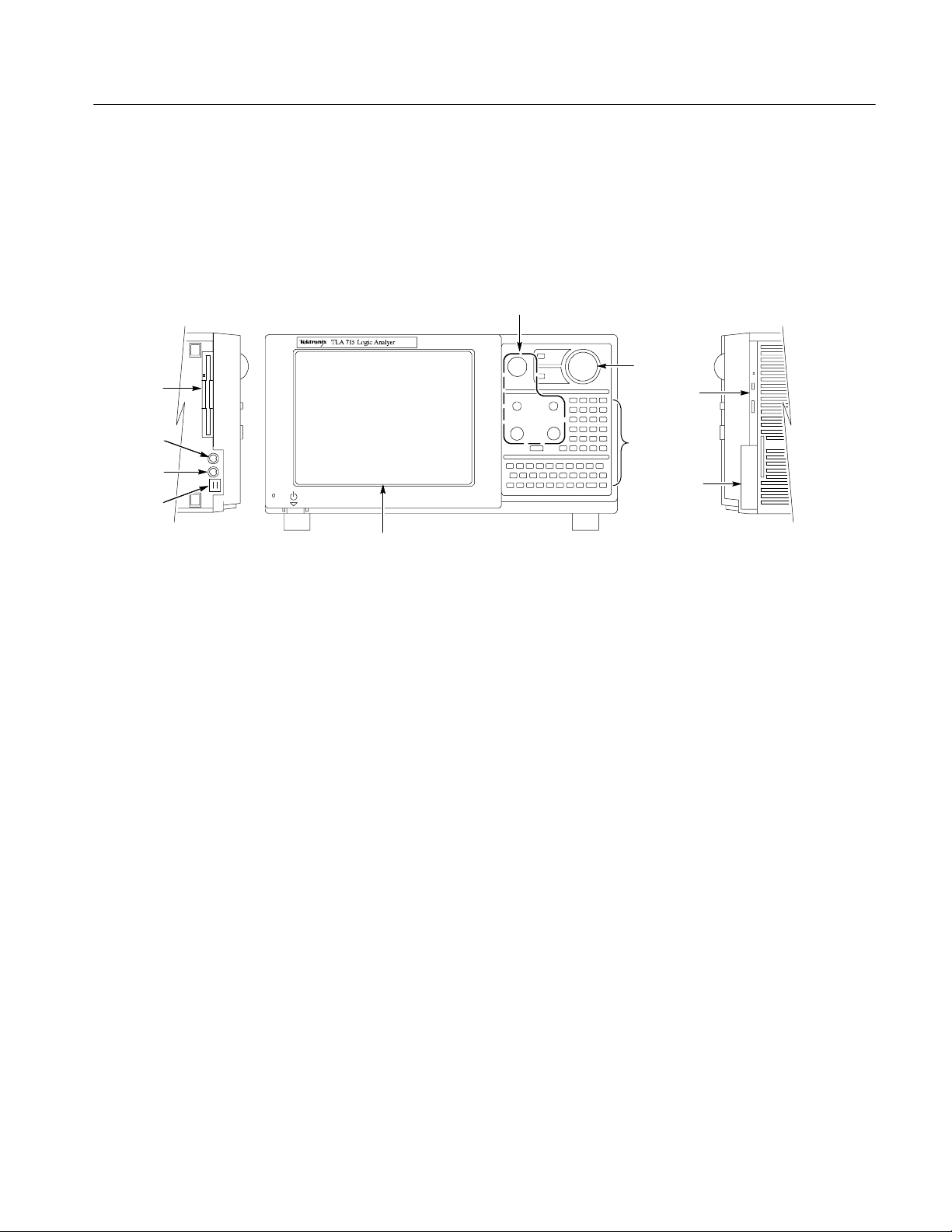
Front Panel and Rear Panel Controls and Connections
This section describes the front panel and rear panel controls and connectors on
the TLA715 Portable Mainframe. Figure 2--3 shows the front panel. Figure 2--4
on page 2--5 shows the rear panel.
Knobs
Floppy disk
drive
Operating Information
Trackball
CD--ROM
Keyboard
Mouse
USB
Color display
Figure 2- 3: TLA715 Portable Mainframe front panel
Color LCD Display
The portable mainframe features a 10.4-inch diagonal, 800 X 600 pixel,
flat-panel LCD color display.
Front Panel Keypad,
Knobs
The front panel of the portable mainframe includes a QWERTY keyboard, a
hexadecimal numeric keypad, and five front panel knobs. The keypads are active
simultaneously with the standard external keyboard. The front panel knobs
include a large multi-function knob and four smaller positioning/scale knobs.
Trackball Pointing Device
The trackball pointing device, vertically mounted on the front panel, can be used
instead of an external mouse when limited bench space is available. The
trackball device and a standard external mouse are active simultaneously.
Front panel
keyboard
Replaceable
hard disk
drive
PC Card Port
There are two PCMCIA card slots that support an industry standard Type I, II, or
III PCMCIA PC card. Table 2--2 shows the pin assignments for the port.
TLA715 Dual Monitor Portable Mainframe Service Manual
2- 3
Page 42

Operating Information
Table 2- 2: PC CardBus32 port pin assignments
Pin number Pin assignment Pin number Pin assignment Pin number Pin assignment
1 GND 24 A5 47 A18
2 D3 25 A4 48 A19
3 D4 26 A3 49 A20
4 D5 27 A2 50 A21
5 D6 28 A1 51 VCC
6 D7 29 A0 52 VPP2
7 CE1* 30 D0 53 A22
8 A10 31 D1 54 A23
9 OE* 32 D2 55 A24
10 A11 33 ISI16* 56 A25
11 A9 34 GND 57 VS2
12 A8 35 GND 58 RESET
13 A13 36 CD1* 59 WAIT*
14 A14 37 D11 60 INPACK*
15 WE* 38 D12 61 REG*
16 IREQ* 39 D13 62 SPKR*
17 VCC 40 D14 63 STSCHG*
18 VPP1 41 D15 64 D8
19 A16 42 CE2* 65 D9
20 A15 43 VS1 66 D10
21 A12 44 IORD* 67 CD2*
22 A7 45 IOWR* 68 GND
23 A6 46 A17
2- 4
USB Ports
There are two USB (universal serial bus) ports. The USB ports can be used for
any USB complaint device. Table 2--3 shows the pin assignments for the USB
port.
Table 2- 3: USB pin assignments
Pin number Pin function Pin number Pin function
A1 Vcc B1 Vcc
A2 ADATA-- B2 BDATA--
A3 ADATA+ B3 BDATA+
A4 GND B4 GND
TLA715 Dual Monitor Portable Mainframe Service Manual
Page 43

Operating Information
Mouse Port
Keyboard Port
Replaceable
Hard Disk Drive
CD ROM Drive
Floppy Disk Drive
External I/O BNCs
The mouse connector is a standard six-pin, PS/2-compliant DIN connector. The
mouse port can be connected to an external, standard PS/2-compliant three-button (wheel) mouse.
The keyboard connector is a standard six-pin PS/2-compliant DIN connector.
The keyboard port can be connected to an external, standard PS/2-compliant
keyboard.
There is a replaceable hard drive. This service manual lists the size of the hard
disk drive available at the time the product was introduced. Consult your
Tektronix Sales Representative for the maximum hard disk drive available.
The mainframe has one CD ROM drive.
The mainframe has one standard 1/2 inch drive that supports 3.5 inch, 1.44 MB,
high-density/double-sided floppy disk media.
The mainframe has four BNC connectors on the rear panel (see Figure 2--4) these
connectors are labeled: SYSTEM TRIG IN, SYSTEM TRIG OUT, EXTERNAL
SIG IN, EXTERNAL SIG OUT.
PC cards (2)
SYSTEM TRIG IN
SYSTEM TRIG OUT
COM port
EXTERNAL SIG IN
EXTERNAL SIG OUT
SECONDARY VIDEO
PRIMARY VIDEO
LPT printer port
Figure 2- 4: Portable mainframe rear panel
TLA715 Dual Monitor Portable Mainframe Service Manual
2- 5
Page 44

Operating Information
SVGA Ports
COM Port
Two SVGA OUT ports support industry standard SVGA color monitors. One
connector is labeled SECONDARY VIDEO and the other is labeled PRIMARY
VIDEO. The connectors are 15-pin, sub-D SVGA-compliant connectors. See
Table 2--4 for pin assignments.
Table 2- 4: SVGA OUT pin assignments
Pin number Pin function Pin number Pin function
1 RED 2 GRN
3 BLU 4 NC
5 GND 6 GND
7 GND 8 GND
9 (KEY) 10 GND
11 NC 12 DDC DAT
13 HSYNC 14 VSYNC
15 DDD CLK
The COM port is an industry standard RS-232 serial port. Table 2--5 shows the
pin assignments.
Table 2- 5: Serial port pin assignments
Pin number Pin function Pin number Pin function
1 DCD 2 RXD
3 TXD 4 DTR
5 GND 6 DSR
7 RTS 8 CTS
9 Ring indicator
2- 6
TLA715 Dual Monitor Portable Mainframe Service Manual
Page 45

Operating Information
LPT Port
The LPT port is a parallel printer port. This parallel printer port supports
standard Centronics mode, Enhanced Parallel Port (EPP), or Microsoft highspeed mode (ECP) and uses a 36-pin high density Centronics-compliant
connector. See Table 2--6 for pin assignments.
Table 2- 6: LPT (parallel interface) pin assignments
Pin number Pin function Pin number Pin function
1 BUSY 19 GND
2 SLCT 20 GND
3 ACK* 21 GND
4 ERR* 22 GND
5 PE 23 GND
6 D0 24 GND
7 D1 25 GND
8 D2 26 GND
9 D3 27 GND
10 D4 28 GND
11 D5 29 GND
12 D6 30 GND
13 D7 31 GND
14 INIT* 32 GND
15 STB* 33 GND
16 SLIN* 34 GND
17 AFD* 35 GND
18 HI 36 GND
See IEEE specification P1284-C for pin connection definitions for other modes
Operating System and Application Interface
The TLA715 Portable Mainframe comes with the Microsoft Windows 2000
Professional operating system factory-installed. Operations and capabilities when
running on the mainframe are the same as with Microsoft Windows running on a
high-performance personal computer. Windows Help is available from the Start
menu of the Windows Task Bar.
TLA715 Dual Monitor Portable Mainframe Service Manual
2- 7
Page 46

Operating Information
The mainframe also comes with the Tektronix Logic Analyzer Family application software configured at the factory to launch after the logic analyzer boots up
and the operating system is running. The application software controls data
acquisition and processing by the logic analyzer. The application software is
included with the product; refer to the Tektronix Logic Analyzer Family User
Manual if you need to reinstall any software.
Online Help
System Window
Setup Window
Trigger Window
Listing Window
Most of the user information for operating the portable mainframe is available
through online help. Refer to the online help for more information on the
individual menus, icons, and fields within each window.
The System window provides an overview of the entire logic analyzer. Use the
System window to navigate through the logic analyzer. The center of the system
window displays icons that represent logic analyzer modules, DSO modules, or
pattern generator modules. These icons provide links to other windows in the
instrument.
A setup window exists for each module in the instrument. It contains the setup
information for the module, such as clocking, memory depth, threshold
information, and channel information.
Each trigger window provides access to the trigger setups. DSO and logic
analyzers have their own trigger windows. Use the trigger window to determine
when you want the logic analyzer or DSO to acquire data and how much data to
acquire.
The listing window displays acquired data as tabular text. Each column of data
represents one group of data or other logical data information, such as time
stamps. Each row represents a different time that data was acquired: newer
samples display below older samples.
2- 8
Waveform Window
Other Windows
The waveform window displays acquired data as graphical waveforms. All
defined channels display as Busforms for the logic analyzer and as individual
data channels for the DSO.
Other windows may exist on the logic analyzer depending on the installed setup.
For more information on the logic analyzer application, refer to the Tektronix
Logic Analyzer Family User Manual.
TLA715 Dual Monitor Portable Mainframe Service Manual
Page 47
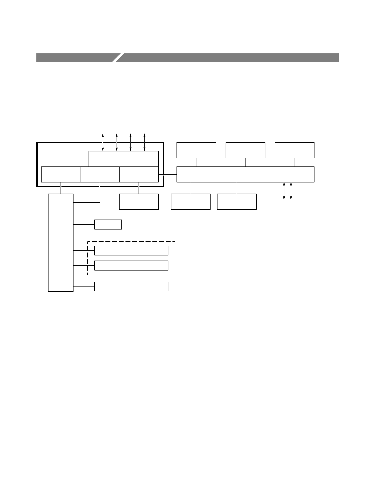
Theory of Operation
This chapter provides a brief overview of the theory of operation for the TLA715
Portable Mainframe. Figure 3--1 shows a functional block diagram of the major
components.
Controller
PC Cards, SVGA, COM1,
EPP & trigger/signal ports
PCI to backplane
bridge ASIC
Backplane
VTC Trig
ASIC
Fans
TLA 700 Series module # 1
TLA 700 Series module # 2
PC Controller
display and I/O
Hard disk
drive(s)
Power supply
Figure 3- 1: TLA715 Portable Mainframe block diagram
Color LCD
display
Floppy disk
drive
Front panel
keypads & knobs
Front panel interface board
CD ROM
drive
Trackball
pointing device
External mouse,
USB, and keyboard
Block Level Description
The following paragraphs provide a high-level overview of the major components of the TLA715 Portable Mainframe. Refer to Figure 3--1 while reading the
following paragraphs.
Controller Board
TLA715 Dual Monitor Portable Mainframe Service Manual
The controller board provides the portable mainframe with a high-performance
PC-based controller architecture, including graphics and I/O, and interfaces to
the backplane bus and the front panel. The controller board mounts vertically on
the left side of the instrument and connects to the back of the backplane. The
controller provides signals to the rear panel and front panel interface.
3- 1
Page 48

Theory of Operation
The controller uses a standard Intel Pentium III microprocessor using the 815E
chip-set. The controller has a 733 MHz Pentium III processor with up to 512 MB
of SDRAM, 16 KB of Li instruction cache, 16 KB of LI data cache, 256 KB of
L2 cache, and 8 MB of flashed-based BIOS.
A ECP/EPP Centronics-compatible parallel port, two USB ports, and two
16550-based serial RS-232 COM ports (one external) support standard PC-based
I/O peripherals.
A Silicon Motion Lynx3DM SVGA/XGA display controller with up to 4 MB of
internal DRAM supports the flat panel LCD display and an external SVGA port.
The 815E chip-set provides and additional SVGA/XGA output port.
The backplane interface appears as a standard PCI device to the PC-based
controller. The PCI-to-Backplane interface is managed by a Tektronix-designed
ADG343 CMOS ASIC which includes support for DMA transfers with FIFO,
IRQ management, programmable byte swapping, backplane address space
management and windowing (A16, A24, and A32 space), backplane arbitration,
and MODID control lines.
Backplane
Front Panel Interface
The backplane trigger lines are managed by the Tektronix-designed Backplane
Trigger Crossbar (VTC) ASIC. The VTC ASIC cross-connects any of the ten
trigger lines (ECL and TTL) to any of the four BNC ports on the rear I/O panel
of the mainframe. The four BNC ports accommodate two inputs (System Trigger
In and External Signal In) and two outputs (System Trigger Out and External
Signal Out). The VTC ASIC also supports several standard trigger protocols
(including START/STOP protocol), which support a synchronous start of all
modules to System Time Zero (STZ), and several custom features including time
interpolation to support the VTC ASIC in individual module applications.
The backplane supports up to four single-wide slots, where most modules require
two slots. The backplane connects the power supply to the rest of the instrument.
It also distributes the 10 MHz system clock and supports all communication to,
from, and between the modules, including real time intermodule communications.
The front panel interface assembly interacts with the system controller, LCD flat
panel display, floppy disk drive, front panel keypad and trackball, USB ports,
mouse, and keyboard. Dual 50-pin cables connect the front panel interface board
to the internal slot-0 controller. The interface also supplies a speaker for the PC.
3- 2
TLA715 Dual Monitor Portable Mainframe Service Manual
Page 49

Theory of Operation
LCD Display
Front Panel Controls
The internal display is a 10.4-inch diagonal Active Matrix Thin-Film-Transistor
(TFT) liquid crystal display with a built-in back light similar to those found in
many notebook PCs. The color-cathode fluorescent back light can be dimmed to
60% of its value via a custom Tektronix screen saver or mainframe utilities
applet to extend its life and to prevent burning of the TFT LCD screen. The LCD
has an external DC switching regulator board to provide the back light high
voltage and a display adapter board which supports interfacing from the front
panel interface board to the LCD display.
The front panel key pad consists of a Hex keypad and a partial QWERTY
keypad. The front panel keypads are active simultaneously with an optional
external keyboard through an MC68HC705B16 front panel processor. The front
panel processor combines the two devices to generate and receive standard
keyboard scan codes from the system controller.
The front panel knobs include the following controls:
H Detented horizontal size control
H Detented vertical size control
H Nondetented horizontal position control
H Nondetented vertical position control
Hard Disk Drives
H A nondetented multifunctional knob
A second MC68HC705B16 control panel processor and a custom WIN32 knob
API (DLL and VxD drivers) control the front panel knobs.
The trackball pointing device is a standard, off-the-shelf OEM PC pointing
device mechanically integrated into the mainframe. The trackball is simultaneously active with an external mouse through the USB. The external mouse
connects directly to the controller through a PS2 interface.
The hard disk drives (HDD) are standard 2.5-inch IDE drives which interface
directly to the system controller through an Enhanced Integrated Device
Electronics (IDE) extension of the PCI bus. The main HDD is easily removable
from the mainframe without removing any covers. The HDD is available in two
configurations: minimum and maximum (the sizes depend on the availability of
the hard disk drives).
The mainframe is electrically capable of accepting dual master-slave IDE HDD
configurations for a total of four drives (or other HDD devices) but is mechanically limited to mounting two drives. The CD-ROM uses the A slot on the
secondary IDE interface which reduces the number of HDD devices to three.
TLA715 Dual Monitor Portable Mainframe Service Manual
3- 3
Page 50

Theory of Operation
Floppy Disk Drive
CD-ROM Drive
Mouse and Keyboard
Ports
USB Ports
Mechanical Chassis
The floppy disk drive is a standard 0.5-inch drive supporting a 3.5-inch,
1.44 MB high-density, double sided floppy disks
The CD-ROM is a standard 24x CD-ROM drive.
The mouse and keyboard ports are standard PS2 compliant ports. They interface
through the front panel processor to the system controller.
A dual USB port is available to connect USB devices to the mainframe.
The mechanical chassis provides the mechanical support structure for the
mainframe and includes the cooling system, modular-card cage, and EMI
shielding system.
3- 4
TLA715 Dual Monitor Portable Mainframe Service Manual
Page 51

Performance Verification Procedures
This chapter contains procedures for functional verification, certification, and
performance verification procedures for the TLA715 Portable Mainframe.
Generally, you should perform these procedures once per year or following
repairs that affect certification.
Summary Verification
Functional verification procedures verify the basic functionality of the instrument inputs, outputs, and basic instrument actions. These procedures include
power-on diagnostics, extended diagnostics, and manual check procedures.
These procedures can be used for incoming inspection purposes.
Certification procedures certify the accuracy of an instrument and provide a
traceability path to national standards. Certification data is recorded on calibration data reports provided with this manual. The calibration data reports are
intended to be copied and used for calibration/certification procedures.
After completing the performance verification procedures or the certification
procedures, you can fill out a calibration data report to keep on file with your
instrument.
Test Equipment
Performance verification procedures confirm that a product meets or exceeds the
performance requirements for the published specifications documented in the
Specifications chapter of this manual. Refer to Figure 4--1 on page 4--2 for a
graphic overview of the procedures.
These procedures use external, traceable signal sources to directly test characteristics that are designated as checked (n)intheSpecifications chapter of this
manual. Table 4--1 on page 4--3 shows the required equipment list. Always
warm up the equipment for 30 minutes before beginning the procedures.
TLA715 Dual Monitor Portable Mainframe Service Manual
4- 1
Page 52

Performance Verification Procedures
Determine equipment
to certify.
Go to appropriate
procedure(s).
Gather required test
equipment.
Photocopy the required
Calibration Data Report(s).
Enter product model and
serial number(s) on the
Calibration Data Report(s).
Use
Tektronix-supplied
probes.
No
Is it OK
with customer to
remove/reconnect probes
from System
Under Test?
Yes
Repair or adjust
equipment as
required.
Allow all mainframes, modules and
equipment to warm up (30 minutes).
Perform procedure.
No
Are
measurements
within
tolerance?
Select procedure.
Configure customer’s
mainframe and modules as
described in procedure.
Set up test equipment.
Figure 4- 1: Calibration/certification pr ocedure flow chart
Enter measurements on
the appropriate
Calibration Data Report.
Create necessary
Calibration Certificate.
No
all certifications
complete?
Yes
Are
Yes
Done
4- 2
TLA715 Dual Monitor Portable Mainframe Service Manual
Page 53

Performance Verification Procedures
Table 4- 1: Test equipment
Item number and description Minimum requirements Example
1. Mainframe TLA715 Portable mainframe with a
LA, DSO, or Patgen module installed
2. Frequency counter Frequency accuracy: <0.0025%
Frequency range: 1 kHz to 100 MHz
3. Miniature probe-to-square pin
adapters
4. 0.025-inch square pin 3/4-inch length, (two required) Tektronix part number 131-1426-XX
5. Digital multimeter
with test leads
6. Cable, precision
50 Ω coaxial
Two required Tektronix part number 103-0177-XX
VDC accuracy: 0.1% from --10 V to
+100 V
50 Ω, 36 in, male-to-male BNC
connectors
Hewlett Packard 5314A
Tektronix DMM 900 Series
Tektronix part number 012-0482-XX
Functional Verification
Table 4--2 lists the functional verification procedures that are available for the
portable mainframe.
Table 4- 2: Functional verification pr ocedures
Instrument Procedure
Portable mainframe Power-on and fan operation
Portable mainframe Extended diagnostics
Portable mainframe TLA Mainframe diagnostics
Portable mainframe CheckIt Utilities diagnostics
NOTE. Running the extended diagnostics will invalidate any acquired data. If
you want to save any of the acquired data, do so before running the extended
diagnostics.
You will need a portable mainframe with an LA or DSO module installed.
Equipment
required
Cable, 50 Ω coaxial (item 6)
Prerequisites Warm-up time: 30 minutes
Perform the following tests to complete the functional verification procedure.
TLA715 Dual Monitor Portable Mainframe Service Manual
4- 3
Page 54

Performance Verification Procedures
Fan Operation
Extended Diagnostics
TLA Mainframe
Diagnostics
Power on the instrument and inspect the rear of the instrument to verify that all
six cooling fans are rotating.
Do the following steps to run the extended diagnostics:
1. If you have not already done so, power on the instrument and wait for the
logic analyzer application to start.
2. Go to the System menu and select Calibration and Diagnostics.
3. Verify that all power-on diagnostics pass.
4. Click the Extended Diagnostics tab.
5. Select All Modules, All Tests and then click the Run button on the property
sheet.
All tests that displayed an “Unknown” status will change to a Pass or Fail
status depending on the outcome of the tests.
6. Scroll through the tests and verify that all tests pass.
The TLA Mainframe Diagnostics are a comprehensive software test that checks
the functionality of the portable mainframe. To run the TLA Mainframe
Diagnostics, do the following steps:
CheckIt Utilities
1. Quit all other applications.
2. Click the Windows Start button.
3. Select Programs → Tektronix Logic Analyzer → TLA Mainframe Diagnos-
tics.
4. Run the mainframe diagnostics by clicking the Run button or the Single-Step button in the tool bar.
CheckIt Utilities is a comprehensive software application used to check and
verify the operation of the PC hardware in the portable mainframe. To run the
software, you must have either a keyboard, mouse, or other pointing device.
NOTE. To check the floppy disk drive or the CD-ROM drive, you must have a test
floppy disk or CD installed before starting the CheckIt Utilities.
4- 4
TLA715 Dual Monitor Portable Mainframe Service Manual
Page 55

To run CheckIt Utilities, follow these instructions:
1. Quit the logic analyzer application.
2. Click the Windows Start button.
3. Select Programs → CheckIt Utilities.
4. Run the tests. If necessary, refer to the CheckIt Utilities online help for
information on running the software and the individual tests.
Portable Mainframe Certification
The system clock is checked for accuracy. The instrument is certifiable if this
parameter meets specifications. Do the performance verification procedures and
record the values on a copy of the calibration data report located at the end of
this chapter.
Performance Verification Procedures
Performance Verification Procedures
Table 4--3 lists the performance verification procedures available for the portable
mainframe.
Table 4- 3: Performance verification procedures
Parameter Procedure
Power supply voltages Voltage level check
System clock (CLK10)
1
Certifiable parameter
Use the following steps to complete the performance verification procedure. You
will need some of the equipment shown in Table 4--1 on page 4--3 to complete
the performance verification procedures. If you substitute equipment, always
choose instruments that meet or exceed the minimum requirements specified.
1
Signal output check
TLA715 Dual Monitor Portable Mainframe Service Manual
4- 5
Page 56

Performance Verification Procedures
Checking Power
Supply Voltages
Do the following to verify power supply performance:
Equipment
required
Prerequisites Warm-up time: 30 minutes for the portable mainframe and test
DMM with test leads (item 5)
Two miniature probe-to-square pin adapters (item 3)
0.025-inch square pin (item 4)
Frequency counter (item 2)
Precision BNC cable (item 6)
equipment
Power-on, mainframe, and QA+WIN32 diagnostics pass
1. Power off the portable mainframe and remove any modules installed in it.
2. Power on the portable mainframe and connect the reference lead of a digital
voltmeter to chassis ground, such as the top of the power supply.
3. Attach a 0.025-inch square pin to the probe tip of the other lead and insert it
into one of the pins on the backplane connectors listed in Table 4--4.
CAUTION. Use of a square pin of other dimensions will damage the backplane
connectors.
The pins that should be carrying voltages are listed in Table 4--4. The arrangement of J1 and J2 connectors on the backplane is shown in Figure 4--2. Measure
the power supply voltages with the voltmeter and compare each reading to the
values listed in the tables. If the voltages are within the ranges listed in the table,
the power supply is operating properly.
Table 4- 4: Power supply voltages and backplane connector pins
J1 pin Voltage (range) J2 pin Voltage (range)
Row A Row A
31 --12 V (--12.60 V to --11.64 V) 2 --2 V (--2.10 V to --1.90 V)
25 +5 V (4.875 V to 5.250 V)
Row C Row C
31 +12 V (11.64 V to 12.60 V) 4 --5.2 V (--5.460 V to --5.044 V)
31 +24 V (23.28 V to 25.20 V)
4- 6
32 --24 V (--25.20 V to --23.28 V)
TLA715 Dual Monitor Portable Mainframe Service Manual
Page 57

Performance Verification Procedures
J2 rows of pins J1 rows of pins
Checking the 10 MHz
System Clock (CLK10)
Figure 4- 2: Location of J1 and J2 pins in the portable mainframe
Do the following to check the accuracy of the system clock.
1. Connect the frequency counter to the External Signal Out TTL BNC
connector on the rear of the portable mainframe.
2. Verify that the logic analyzer application is running.
3. Go to the System window and select System Configuration from the System
menu.
4. In the System Configuration dialog box, select 10 MHz Clock from the list
of routable signals in the External Signal Out selection box and click OK.
5. Verify that the output frequency at the External Signal Out TTL connector is
10 MHz ±1 kHz. Record the measurement on a copy of the calibration data
report.
6. In the system configuration dialog box, reset the External Signal Out signal
to None.
7. Disconnect the frequency counter and power off the portable mainframe.
8. Reinstall any modules that were removed at the beginning of the perfor-
mance verification procedure.
TLA715 Dual Monitor Portable Mainframe Service Manual
4- 7
Page 58

Performance Verification Procedures
4- 8
TLA715 Dual Monitor Portable Mainframe Service Manual
Page 59

Calibration Data Report
TLA715 Portable Mainframe
Instrument model number:
Serial number: Certificate number:
Verification performed by: Verification date:
System Clock Test Data
Procedure
Characteristic Specification Tolerance
Clock frequency 10 MHz ±1 kHz (9.9990 MHz-10.0010 MHz) Page 4--7,
reference
Step 5
Incoming data Outgoing data
Page 60

Page 61

Adjustment Procedures
There are no adjustments for the Portable Mainframe. For adjustment procedures
on the individual modules, refer to the appropriate module service manual.
TLA715 Dual Monitor Portable Mainframe Service Manual
5- 1
Page 62

Adjustment Procedures
5- 2
TLA715 Dual Monitor Portable Mainframe Service Manual
Page 63

Maintenance
Preparation
Preventing ESD
This chapter provides procedures for inspecting and cleaning the portable
mainframe, removing and replacing internal chassis components, and isolating
problems to the board or replacement part level.
To repair, you must exchange or replace the failed part; this manual does not
provide component-level procedures for isolating components on the failed part.
The information in this chapter is designed for use by qualified service personnel. Read the Safety Summary at the front of this manual before attempting any
procedures in this chapter. Refer to the Operating Information chapter for
information on the location of controls, indicators, and connectors used with the
chassis.
When performing any service which requires internal access to the instrument,
adhere to the following precautions to avoid damaging internal circuit boards and
their components due to electrostatic discharge (ESD).
CAUTION. Many components within the chassis are susceptible to staticdischarge damage. Service the chassis only in a static-free environment.
Observe standard handling precautions for static-sensitive devices while
servicing the chassis.
Always wear a grounded wrist strap, or equivalent, while servicing the chassis.
1. Minimize handling of static-sensitive circuit boards.
2. Transport and store static-sensitive circuit boards in their static protected
containers or on a metal rail. Label any package that contains static-sensitive
boards.
3. Discharge the static voltage from your body by wearing a grounded antistatic
wrist strap while handling these circuit boards. Do service of static-sensitive
circuit boards only at a static-free work station.
4. Do not allow anything capable of generating or holding a static charge on the
work station surface.
TLA715 Dual Monitor Portable Mainframe Service Manual
6- 1
Page 64

Maintenance
5. Handle circuit boards by the edges when possible.
6. Do not slide the circuit boards over any surface.
7. Avoid handling circuit boards in areas that have a floor or work-surface
WARNING. To avoid electric shock, always power off the chassis and disconnect
the power cord before cleaning or servicing the chassis.
Inspection and Cleaning
The instrument is inspected mechanically and electrically before shipment. It
should be free of marks or scratches and should meet or exceed all electrical
specifications. To confirm this, inspect the chassis for physical damage incurred
during transit. Retain the chassis packaging in case shipment for repair is
necessary. If there is damage or deficiency, contact your local Tektronix
representative.
covering capable of generating a static charge.
Interior Cleaning
Exterior Cleaning
Cleaning procedures consist of exterior and interior cleaning of the chassis.
Clean the chassis as needed, based on the operating environment. Refer to the
appropriate module service manuals for information on cleaning individual
TLA700 Series modules.
Use a dry, low-velocity stream of air to clean the interior of the chassis. Use a
soft-bristle, non-static-producing brush for cleaning around components. If you
must use a liquid for minor interior cleaning, use a 75% isopropyl alcohol
solution and rinse with deionized water.
Clean the exterior surfaces of the chassis with a dry lint-free cloth or a softbristle brush. If any dirt remains, use a cloth or swab dipped in a 75% isopropyl
alcohol solution. Use a swab to clean narrow spaces around controls and
connectors. Do not use abrasive compounds on any part of the chassis that may
damage the chassis.
Clean the On/Standby switch using a dampened cleaning towel. Do not spray or
wet the switch directly.
6- 2
TLA715 Dual Monitor Portable Mainframe Service Manual
Page 65

Maintenance
CAUTION. Avoid getting moisture inside the chassis during exterior cleaning; use
just enough moisture to dampen the cloth or swab.
Do not wash the front-panel On/Standby switch. Cover the switch while washing
the chassis.
Use only deionized or distilled water when cleaning. Use a 75% isopropyl
alcohol solution as a cleanser and rinse with deionized or distilled water.
Do not use chemical cleaning agents; they may damage the chassis. Avoid
chemicals that contain benzene, toluene, xylene, acetone, or similar solvents.
Flat Panel Display
Cleaning
The LCD display is a soft plastic display and must be treated with care during
cleaning.
CAUTION. Improper cleaning agents or methods can damage the flat panel
display.
Avoid using abrasive cleaners or commercial glass cleaners to clean the display
surface.
Avoid spraying liquids directly on the display surface.
Avoid scrubbing the display with excessive force.
Clean the flat panel display surface by gently rubbing the display with a
clean-room wipe (such as Wypall Medium Duty Wipes, #05701, available from
Kimberly-Clark Corporation).
If the display is very dirty, moisten the wipe with distilled water or a 75%
isopropyl alcohol solution and gently rub the display surface. Avoid using excess
force or you may damage the plastic display surface.
TLA715 Dual Monitor Portable Mainframe Service Manual
6- 3
Page 66

Maintenance
6- 4
TLA715 Dual Monitor Portable Mainframe Service Manual
Page 67

Removal and Installation Procedures
This section contains procedures for removal and installation of all mechanical
and electrical field-replaceable parts. You may also want to refer to the exploded
view illustrations in the Mechanical Parts List chapter at the end of this
document to get an overall view how all the instrument parts fit together.
WARNING. Before performing this or any other procedure in this manual, read
the safety summaries found at the beginning of this manual.
T o prevent possible injury to service personnel or damage to the portable
mainframe, read Installation on page 2--1, and Preventing ESD on page 6-- 1 in
this section.
WARNING. Dangerous voltages may be present when instrument covers are
removed. Before performing any procedure in this section, disconnect the power
cord from the line voltage source. Failure to do so could cause serious injury or
death.
Read all instructions before removing a part. Following these instructions helps
ensure that you remove the part to be serviced while removing the minimum
number of additional parts. Refer to the Mechanical Parts List at the end of this
document for descriptions and part numbers of all replaceable parts in the
instrument.
TLA715 Dual Monitor Portable Mainframe Service Manual
6- 5
Page 68

Removal and Installation Procedures
Equipment Required
Most parts in this mainframe can be removed with a screwdriver with a T-15
Torx tip. Table 6--1 lists additional tools that may be required to service the
instrument to the module level.
Table 6- 1: Equipment required to service t he portable mainframe
Item number Item Description
1 Flat blade screwdriver Small flat blade screwdriver
2 Cutters Diagonal cutters (for removing cable ties)
3 Spudger tool Used for removing the trim ring
4 Torque screwdriver han-
dle
5 T-15 Torx tip Torx drive bit for T-15 size screws
6 T-10 Torx tip Torx drive bit for T-10 size screws
7 Phillips screwdriver Phillips #1 screwdriver and 6-inch long shaft
8 Needle nose plier
9 Soldering iron, solder,
solder wick
10 Cable ties 4-inch tie-down straps (Tektronix part number
11 Scribe Scribe or jeweler’s screwdriver
Accepts Torx driver bits
For replacing soldered components
343-0549-00)
NOTE. When installing the screws, use a torque screwdriver and tighten the
screws to 8 in-lbs unless otherwise noted.
6- 6
TLA715 Dual Monitor Portable Mainframe Service Manual
Page 69

Removing the Replaceable Hard Disk Drive
Complete the following steps to remove the replaceable hard disk drive from the
mainframe. You should always remove the hard disk drive before accessing any
of the replaceable components in the instrument.
CAUTION. Do not remove the replaceable hard disk drive while the instrument is
powered on. You can permanently damage the replaceable hard disk drive if you
remove it while the instrument is powered on. Always power down the mainframe before removing the replaceable hard disk drive.
1. Power down the instrument.
2. Press the latch on the side of the instrument as shown in Figure 6--1 to
unlatch the hard disk drive.
3. Remove the hard disk drive from the instrument by pulling on the handle.
Removal and Installation Procedures
Figure 6- 1: Removing the replaceable hard disk drive
4. To replace the hard disk in the cartridge, remove the four screws that fasten
the hard disk drive to the cartridge shown in Figure 6--2.
5. Carefully remove the hard disk drive from the cartridge, and remove the
cable assembly from the connector on the hard disk drive.
TLA715 Dual Monitor Portable Mainframe Service Manual
6- 7
Page 70

Removal and Installation Procedures
6. When you reinstall the four screws, start the screws by hand and then tighten
Figure 6- 2: Removing the hard disk drive from the cartridge
them to 4 in-lbs.
Remove 4 screws
Accessories Pouch
NOTE. The remaining procedures in this section assume that the removable hard
disk drive is not installed in the controller.
The accessories pouch is held in place on the top cover by snaps. Gently lift up
on each corner of the pouch until the pouch snaps free from the top cover. To
reinstall the pouch, align the pouch over each snap and push down on the corners
of the cover (it may be easier to open the pouch and press down on the corners
from inside the pouch).
NOTE. The remaining procedures assume that you have removed the accessories
pouch.
6- 8
TLA715 Dual Monitor Portable Mainframe Service Manual
Page 71
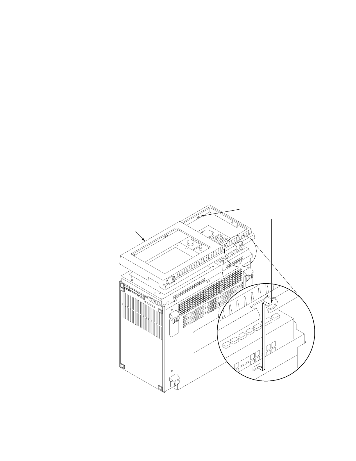
Trim Ring
Removal and Installation Procedures
You will need a spudger tool to remove the trim ring.
Removal
Installation
Use the following procedure to remove the trim ring:
1. Set the mainframe with the cord-wrap feet on the work surface and the
bottom facing you.
2. Use the spudger tool to detach the three plastic snaps from the bottom cover
(see Figure 6--3). Then, swing the bottom of the ring upward and work the
rest of the ring off the front panel.
To replace the trim ring on the front panel. Place the trim ring on the front panel.
Start at the top edge and work around to the bottom until the three plastic snaps
engage. Press the trim ring down around each edge until it is completely seated.
When removing the trim ring,
grasp its bottom edge and flex it
toward you before pulling upward.
Trim ring
Figure 6- 3: Trim ring removal
TLA715 Dual Monitor Portable Mainframe Service Manual
6- 9
Page 72

Removal and Installation Procedures
Flat Panel Display Assembly
You will need a screwdriver with a size T-15 Torx tip to perform this procedure.
Removal
Use the following procedure to remove the flat panel display assembly:
1. Remove the trim ring using the procedure on page 6--9.
2. Remove the five screws that attach the flat panel display assembly to the
mainframe: two screws at the bottom of the assembly on the front of the
instrument, one screw on the left side, and two screws on the top. (See
Figure 6--4).
3. Lift the bottom edge of the flat panel display assembly and rotate it upward
and off the front face of the instrument.
4. Detach the ribbon cable connecting the flat panel display assembly to the
front panel interface board.
5. Detach the five-pin display backlight power connector and then set the
assembly aside.
NOTE. When removing the flat pane display assembly, make sure that you do not
lose the clear plastic light pipe that is located inside the bottom left corner of the
assembly.
6- 10
Installation
Use the following procedure to reinstall the flat panel display assembly:
1. Reattach the cable connecting the flat panel display assembly to the interface
board.
2. Reattach the display backlight power cable.
3. Reinstall the flat panel display assembly by first inserting the top edge and
then rotating it downward into position. (Be sure the tabs are engaged at the
top of the assembly. Insert the five screws that attach the flat panel display
assembly to the mainframe: two screws at the bottom of the assembly on the
front of the instrument, two screws on the top, and one screw on the left side.
(See Figure 6--4).
4. Reinstall the trim ring.
TLA715 Dual Monitor Portable Mainframe Service Manual
Page 73
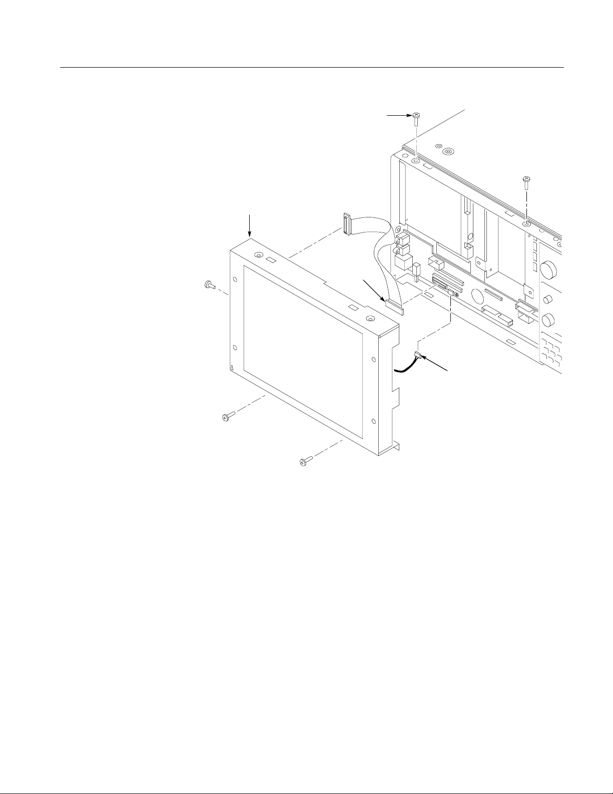
Flat panel display
assembly
Removal and Installation Procedures
Remove screws (5)
Disconnect
the cable
Figure 6- 4: Flat panel display assembly removal
Display
backlight
cable
TLA715 Dual Monitor Portable Mainframe Service Manual
6- 11
Page 74

Removal and Installation Procedures
Floppy Disk Drive
You will need a torque screwdriver with a size T-15 Torx tip and a Phillips #0 tip
to perform this procedure.
Removal
Installation
Use the following procedure to remove the floppy disk drive:
1. Remove the trim ring.
2. Do the Flat Panel Display Assembly removal procedure.
3. Detach the data cable from J103 on the front panel interface board; there is a
locking latch on both the floppy disk drive and on the interface board
connectors.
4. Remove the two screws securing the floppy disk drive assembly to the
chassis.
5. Remove the floppy disk drive assembly.
6. Remove the data cable from the floppy disk drive assembly.
7. Use a small Phillips screwdriver to remove the two screws holding the
floppy disk drive to the bracket.
8. Remove the floppy disk drive from the bracket.
To install the floppy disk drive, complete the removal procedures in reverse
order. When you reinstall the Phillips screws, tighten them to 4 in-lbs.
6- 12
NOTE. When you reinstall the data cable on the floppy disk drive assembly and
on the interface board, lift up the locking latch before you insert the cable in the
connector. When the cable is in place, apply pressure to the cable and push the
locking latch closed.
TLA715 Dual Monitor Portable Mainframe Service Manual
Page 75

Fixed Hard Disk Drive
Removal and Installation Procedures
A fixed hard disk drive is available through the TLA7UP mainframe upgrade kit;
the fixed hard disk drive is not normally installed in the mainframe unless the
instrument has been upgraded through the TLA7UP kit. Use the following
procedures to replace the hard disk drive. The fixed hard disk drive is mounted to
the chassis behind the display assembly (see Figure 6--5).
Prior to performing these procedures, back up any files that you want saved to
another computer, file server, removeable hard disk drive, or other media.
You will need a screwdriver with a size T-15 Torx tip to perform this procedure.
Removal
Installation
Use the following procedure to remove the fixed hard disk drive:
1. Remove the trim ring using the procedure on page 6--9.
2. Do the Flat Panel Display Assembly removal procedure on page 6--10.
3. Disconnect the data cable to the fixed hard disk drive.
4. Remove the four screws that hold the fixed hard disk drive bracket to the
chassis as in Figure 6--5.
5. Remove the screws holding the hard disk drive to the bracket.
Use the following procedure to install the fixed hard disk drive.
1. Remove the slave jumper from the old fixed hard disk drive and place it in
the correct (or similar) position on the new fixed hard disk drive.
2. Position the fixed hard disk drive and attach it to the bracket with the two
screws as shown in figure 6--5.
3. Position the fixed hard disk drive bracket in the chassis and install the four
screws that hold the bracket in place.
4. Connect the data cable to the fixed hard disk drive.
5. Reinstall the flat panel display assembly.
6. Reinstall the trim ring.
7. Verify proper operation by running the Power-on diagnostics and the CheckIt
Utilities on the memory, and disk drive verification.
TLA715 Dual Monitor Portable Mainframe Service Manual
6- 13
Page 76
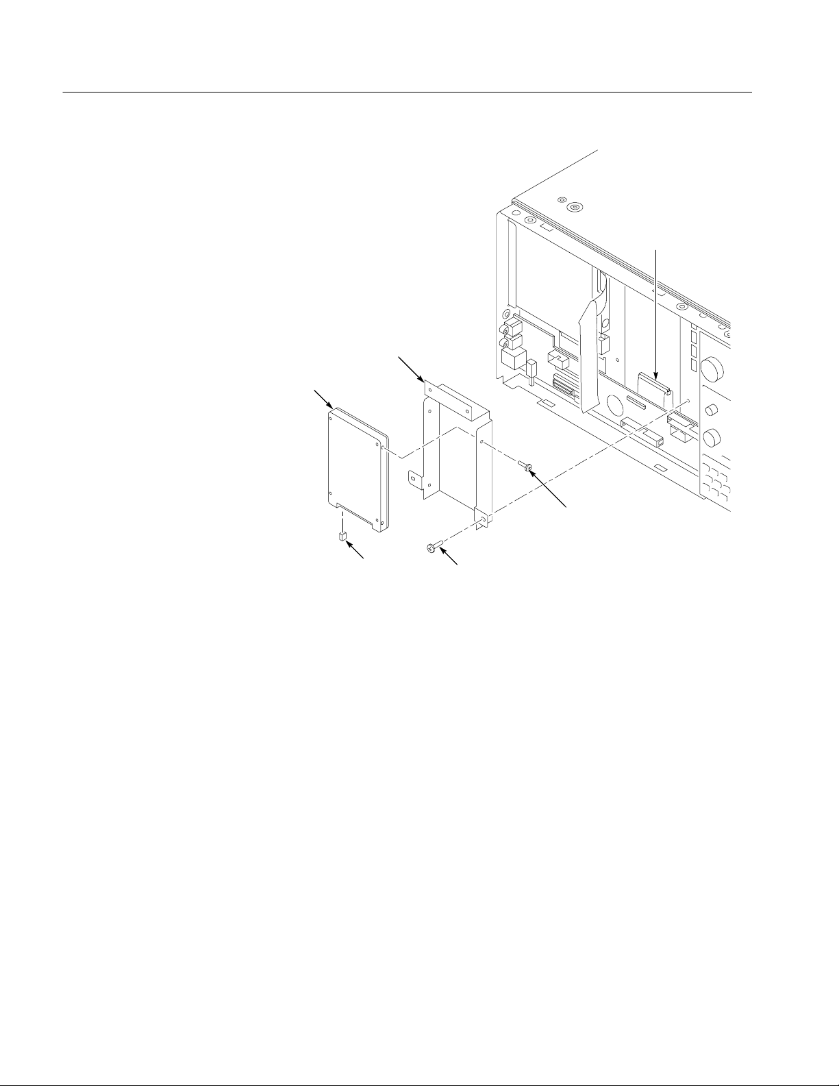
Removal and Installation Procedures
Fixed hard
disk drive
Connector for
the hard disk
drive
Fixed hard disk
drive bracket
Slave
jumper
Screws (4)
Figure 6- 5: Installing the fixed hard disk drive
Screws (4)
6- 14
TLA715 Dual Monitor Portable Mainframe Service Manual
Page 77

Front Panel Interface Board
You will need a screwdriver with a T-15 Torx head and a small Phillips
screwdriver to perform this procedure. You may have to remove the left side
cover to access the two Phillips screws on the front left side of the instrument.
Removal and Installation Procedures
Removal
Installation
The front panel interface board is located under the front panel display. Use the
following procedure to remove the interface board:
1. Remove the trim ring.
2. Remove the four screws holding the top cover on the instrument and then set
the top cover aside.
3. Remove the left side cover from the instrument by sliding it away from the
bottom cover; set the left side cover aside (you may also need to loosen the
screws on the bottom cover before you can remove the left side cover).
4. Do the Flat Panel Display Assembly removal procedure on page 6--10.
5. Detach the ribbon cables at J100, J101, J102, and J103.
6. Remove the one screw securing the interface board.
7. Use a small Phillips screwdriver to remove the two screws on the side panel.
8. Grasp the board and slide the board to the right (toward the front panel
control assembly) and lift the board out.
To install the front panel interface board complete the removal procedures in
reverse order .
Front Panel Control Assembly
You will need a screwdriver with a size T-15 Torx tip to perform this procedure.
Removal
TLA715 Dual Monitor Portable Mainframe Service Manual
Use the following procedure to remove the front panel control assembly:
1. Remove the trim ring.
2. Do the Flat Panel Display Assembly removal procedure, page 6--10.
3. Disconnect the cable at J102 on the front panel interface board.
4. Remove the four screws that attach the front panel control assembly to the
mainframe: two at the bottom of the assembly on the front of the instrument,
two on the top. (See Figure 6--6 on page 6--16).
6- 15
Page 78

Removal and Installation Procedures
5. Lift the bottom edge of the front control panel assembly and rotate it up and
6. Detach the ribbon cable connecting the CD-ROM to the interface board.
off the front face of the mainframe.
Remove 2 short screws
6- 16
Disconnect
the cable
Remove 2 short
screws
Front panel control
assembly
Figure 6- 6: Front-panel control assembly removal
TLA715 Dual Monitor Portable Mainframe Service Manual
Disconnect
the cable
Page 79

Removal and Installation Procedures
Installation
Use the following procedure to install the front panel control assembly:
1. Reattach the cable connecting the CD-ROM to the interface board.
2. Reattach the cable from the front panel control assembly to J102 on the
interface board.
3. Reinstall the front panel control assembly by first inserting the top edge and
then rotating it downward into position. (Be sure the tabs are engaged at the
top of the assembly.
4. Insert the four short screws that attach the front panel control assembly to the
mainframe (See Figure 6--6 on page 6--16).
NOTE. Make sure that you only use the short screws on the front panel control
assembly. You will be unable to install the removable hard disk if you use longer
screws.
5. Reinstall the Front Panel Display assembly.
6. Install the trim ring.
CD-ROM Drive
Installation
Removal
The CD-ROM drive is attached to the underside of the front panel control
assembly. You will need a screwdriver with a size T-15 Torx tip and a small
Phillips screw driver.
Use the following procedure to remove the CD-ROM drive:
1. Remove the trim ring.
2. Do the Front Panel Display Assembly removal procedure on page 6--10.
3. Do the Front Panel Control Assembly removal on page 6--15.
4. Remove the four screws that attach the CD-ROM drive to the front panel
control assembly.
5. Remove the small Phillips screws that hold the CD-ROM drive to the
bracket and then slide the CD-ROM drive out of the bracket.
6. Disconnect the CD-ROM interface board from the CD-ROM drive.
To reinstall the CD-ROM drive, install the CD-ROM interface board, position
the CD-ROM drive within the bracket, and then complete the removal procedures in reverse order.
TLA715 Dual Monitor Portable Mainframe Service Manual
6- 17
Page 80

Removal and Installation Procedures
Trackball Assembly
The trackball device is replaced as part of a larger assembly, consisting of the
trackball device, trackball cable, front panel controls frame, and trackball
bracket.
You will need a screwdriver with a size T-15 Torx tip to perform this procedure.
Removal
Use the following procedure to remove the trackball assembly:
1. Do the Front Panel Control Assembly removal procedure on page 6--15.
2. Remove the CD-ROM drive assembly from the front panel control assembly.
3. Refer to Figure 6--7 and detach the trackball cable at the two connectors on
the trackball assembly.
4. Remove the four screws holding the trackball assembly to the front panel
control assembly.
Remove screws (4)
Bracket
Trackball Assembly
Connecter
6- 18
Figure 6- 7: Front panel control assembly parts locations
TLA715 Dual Monitor Portable Mainframe Service Manual
Page 81

Removal and Installation Procedures
Installation
To install the trackball assembly, position the trackball assembly as shown in
Figure 6--7 and then complete the removal procedure in reverse order.
Front Panel Control Board
You will need a screwdriver with a size T-15 Torx tip and a flat-bladed screwdriver or other small prying tool to perform this procedure.
Removal
Use the following procedure to remove the front panel control board:
1. Do the Front Panel Control Assembly removal procedure (page 6--15).
2. Position the assembly face-down on a clean working surface and remove the
3. Turn the assembly over and then remove the knobs from the front of the
4. Detach the trackball cable at the connector on front panel control board.
5. Remove the six screws that attach the front panel control board to the front
CD-ROM drive assembly and set it aside.
front panel control assembly by grasping them and pulling them up and
away from the assembly.
panel control assembly as shown in Figure 6--8.
6. Gently use the prying tool in the slots on the top and bottom of the control
assembly to work the control board free.
7. Lift the front panel control board out of the assembly.
TLA715 Dual Monitor Portable Mainframe Service Manual
6- 19
Page 82

Removal and Installation Procedures
remove/attach elastomeric
keypad from/to front panel
Remove screws (6)
Front panel
control board
Use rubber pull points to
control board
Elastomer keypad
Installation
Figure 6- 8: Front panel control assembly parts locations
Use the following procedure to reinstall the front panel control board:
1. Carefully work the control board into position, making sure that all keys go
through their holes in the front panel and that the board is firmly seated.
2. Insert the six screws that attach the front panel control board to the front
panel control assembly.
3. Reattach the trackball cable.
4. Replace the knobs on the front panel.
NOTE. When you reinstall the CD-ROM drive assembly, make sure that you do
not damage the front panel knobs by applying too much preasure on the back of
the front panel control assembly.
5. Reinstall the CD-ROM drive assembly.
6. Reinstall the front panel assembly.
6- 20
TLA715 Dual Monitor Portable Mainframe Service Manual
Page 83

Elastomeric Keypad
Removal and Installation Procedures
You will need a screwdriver with a size T-15 Torx tip to perform this procedure.
Removal
Installation
Use the following procedure to remove the elastomeric keypad:
1. Do the Front Panel Control Assembly removal procedure on page 6--15.
2. Do the Front Panel Control Board removal procedure on page 6--19.
3. Pull on the rubber pull-points from the front to remove the keypad from the
Front Panel Control Board.
Use the following procedure to reinstall the keypad:
1. Pull the rubber pull-points through the Front Panel Control Board to install
the keypad.
NOTE. When replacing the top two keys next to the trackball assembly, the
rubber of the keypad should line up with the edge of the board.
2. Do the Front Panel Control Board installation procedure.
3. Do the Front Panel Control Assembly installation procedure.
4. Reinstall the trim ring.
TLA715 Dual Monitor Portable Mainframe Service Manual
6- 21
Page 84

Removal and Installation Procedures
Card Guides
The following procedure applies to the card guide and shutter assembly. You will
need a small flat-bladed screwdriver or other small prying tool to perform this
procedure. You can perform this procedure without removing any covers from
the instrument.
Removal
Use the following procedure to remove the card guides or the shutter assembly:
1. Position the instrument with the side facing you so that you can easily access
the card guides or the shutter assembly.
2. Refer to Figure 6--9 and locate the card guide tabs.
3. Use a small, flat-blade screwdriver to gently pry back the tabs until the card
guide or the shutter assembly pops loose.
4. Slide the card guide or shutter assembly out of the instrument.
Pry back the tabs
6- 22
Card guides
Figure 6- 9: Removing the card guide or the shutter assembly
TLA715 Dual Monitor Portable Mainframe Service Manual
Page 85

Removal and Installation Procedures
Installation
Use the following procedure to install the card guide or the shutter assembly:
1. Insert the card guide or shutter assembly into the chassis opening.
2. Refer to Figure 6--10 and align the card guide pegs with the holes in the rear
of the chassis.
3. Insert the card guide pegs into the chassis holes.
4. Snap the card guide tabs in to the chassis slots near the front of the chassis.
5. For the shutter assembly, verify that the shutters open when you push against
the shutter tabs.
Align the four chassis holes
Figure 6- 10: Installing the card guide or shutter assembly
TLA715 Dual Monitor Portable Mainframe Service Manual
Card guides
6- 23
Page 86

Removal and Installation Procedures
Bottom Cover and Feet
You will need a screwdriver with a size T-15 Torx tip and a small Phillips
screwdriver to perform this procedure.
NOTE. The T--15 Torx screws holding the plastic covers and the bottom cover in
place are longer than the rest of the T-15 Torx screws in the instrument. Avoid
mixing these screws up when reassembling the instrument.
Removal
Use the following procedure to remove the bottom cover:
1. Set the mainframe with the cord-wrap feet on the work surface and the
bottom facing you.
2. Remove the four screws that attach the bottom cover to the mainframe.
3. Lift bottom cover off.
4. To remove the flip stand or rear feet, remove the two Phillips screws
attaching the flip stand or rear foot to the bottom cover. (See Figure 6--11.)
Remove
screws (2)
6- 24
Rear feet
Flip stands
Figure 6- 11: Flip stand and rear feet removal
TLA715 Dual Monitor Portable Mainframe Service Manual
Page 87

Removal and Installation Procedures
Top Cover
Installation
Removal
Reposition the bottom cover on the bottom surface of the portable mainframe.
Insert the four screws that attach the bottom cover to the mainframe.
You will need a screwdriver with a size T-15 Torx tip to perform this procedure.
NOTE. The T--15 Torx screws holding the plastic covers and the bottom cover in
place are longer than the rest of the T-15 Torx screws in the instrument. Avoid
mixing these screws up when reassembling the instrument.
Use the following procedure to remove the top cover:
1. Set the mainframe with the bottom on the work surface and the front facing
you.
2. Unsnap the accessories pouch from the top cover.
3. Remove the trim ring.
4. Remove the four screws that attach the top cover to the mainframe. (See
Figure 6--12.)
5. Lift the top cover off.
TLA715 Dual Monitor Portable Mainframe Service Manual
6- 25
Page 88

Removal and Installation Procedures
Screws (4)
Top cover
Left side
cover
Installation
Screws (2)
Right side cover
Figure 6- 12: Top and side cover removal
Reposition the top cover on the instrument and then complete the removal
procedures in reverse order.
6- 26
TLA715 Dual Monitor Portable Mainframe Service Manual
Page 89

Left Side Cover
Removal and Installation Procedures
You will need a screwdriver with a size T-15 Torx tip to perform this procedure.
Removal
Installation
Right Side Cover
Removal
Use the following procedure to remove the left side cover:
1. Remove the trim ring.
2. Do the Top Cover removal procedure on page 6--25.
3. Loosen the two screws on the bottom cover closest to the left side of the
mainframe.
4. Remove the left side cover.
Reposition the left side cover and tighten the two bottom cover screws nearest
the left side of the mainframe. Reinstall the top cover and then the trim ring.
You will need a screwdriver with a size T-15 Torx tip to perform this procedure.
Use the following procedure to remove the left side cover:
1. Remove any installed modules.
2. Remove the trim ring.
3. Locate and unplug the line cord from the right side of the instrument (See
Figure 6--13).
4. Grasp the line cord on either side of the retaining clamp and then rotate the
line cord 90 degrees counterclockwise.
5. Pull the line cord and clamp away from the side panel mounting hole.
6. Do the Top Cover removal procedure on page 6--25.
7. Loosen the two screws on the bottom cover closest to the right side of the
mainframe.
8. Remove the two screws that attach the right side cover to the power supply.
(See Figure 6--12 on page 6--26.)
9. Remove the right side cover.
TLA715 Dual Monitor Portable Mainframe Service Manual
6- 27
Page 90

Removal and Installation Procedures
3 Pull
2 Rotate
Installation
1 Unplug
Figure 6- 13: Removing the line cord from the right side cover
To reinstall the right side cover, complete the removal procedures in reverse
order.
6- 28
TLA715 Dual Monitor Portable Mainframe Service Manual
Page 91

Power Supply
Removal and Installation Procedures
You will need a screwdriver with a size T-15 Torx tip to perform this procedure.
Removal
Use the following procedure to remove the power supply:
1. Do the removal procedures for Bottom Cover and Feet (page 6--24), Top
Cover (page 6--25), and Right Side Cover (page 6--27).
2. Remove the four screws from the right side and the four screws from the
bottom that secure the power supply to the chassis (see Figure 6--14).
Power supply
Remove power
supply screws (4)
Figure 6- 14: Power supply removal
3. Pull on the handle to remove the power supply from the chassis.
NOTE. Replacement power supplies do not come equipped with a power supply
panel or handle.
4. Remove the two inner screws connecting the handle to the power supply.
(See Figure 6--15) and then lift off the plastic handle mount and handle.
5. Remove the panel from the power supply by lifting it off.
TLA715 Dual Monitor Portable Mainframe Service Manual
Remove screws (4)
6- 29
Page 92
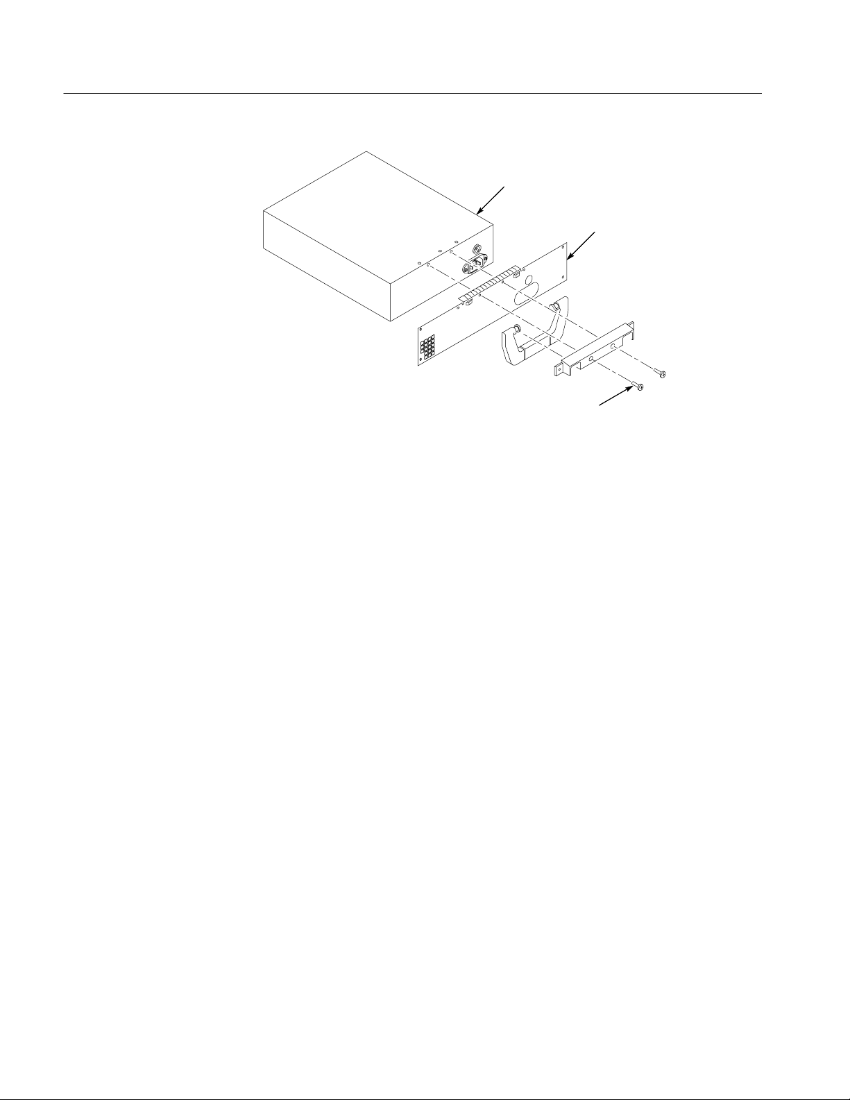
Removal and Installation Procedures
Figure 6- 15: Removing the handle and the panel from the power supply
Power supply
Panel
Remove inner
screws (2)
Installation
Rear Chassis Fan Tray
Removal
To reinstall the power supply, complete the removal procedures in reverse order.
When you insert the power supply into the chassis, press firmly to make sure the
power supply connectors are fully seated.
You will need a screwdriver with a size T-15 Torx tip to perform this procedure.
Use the following procedure to remove the rear chassis fan tray:
1. Set the mainframe so that the bottom is on the work surface and the rear
chassis fan tray faces you.
2. Remove the four screws located within the cord-wrap feet that secure the rear
chassis fan tray to the mainframe. (See Figure 6--16.)
3. Grasp the left cord-wrap foot (facing the fan tray) and swing the left side of
the fan tray away from the mainframe.
4. Disconnect the cable connecting the rear chassis fan tray to the backplane
board.
5. Remove the rear chassis fan tray.
6- 30
TLA715 Dual Monitor Portable Mainframe Service Manual
Page 93

Removal and Installation Procedures
Installation
Use the following procedure to reinstall the rear chassis fan tray:
1. Redress the cable connecting the rear chassis fan tray to the backplane board
if necessary.
2. Reconnect the cable connecting the rear chassis fan tray to the backplane
board.
3. Reposition the rear chassis fan tray.
4. Reposition the cord-wrap feet (they snap into holes on the rear chassis fan
tray), and insert the four screws that secure the rear chassis fan tray to the
mainframe.
Disconnect
Figure 6- 16: Rear chassis fan tray removal
TLA715 Dual Monitor Portable Mainframe Service Manual
Cord-wrap feet
Fan tray
Remove
screws (4)
6- 31
Page 94

Removal and Installation Procedures
Individual Fans
You will need a screwdriver with a size T-15 Torx tip, a Philips screwdriver,
pliers, a side cutter, and a scribe or jeweler’s screwdriver or other small, pointed
tool to perform this procedure.
Removal
Use the following procedure to remove an individual fan from the rear chassis
fan tray:
1. Do the Rear Chassis Fan Tray removal procedure, page 6--30.
2. Remove the screw that secures the hold down brackets to the rear chassis fan
tray. (See Figure 6--17 on page 6--33.) If you are replacing one of the two
fans nearest the cable connector, you need remove only one of the hold-down
brackets. Otherwise, remove two.
3. Lift the fan from the rear chassis fan tray. If necessary, use the pliers to
gently straighten the metal tabs holding the fan to the rear chassis fan tray
and then remove the fan.
4. Note the fan cable dress and remove the tie holding the cables together near
the connector. Remove the cable tie(s) if necessary.
5. Remove the fan wires from the cable connector. (Pay attention to the wire
color locations for reinstallation.) Use a scribe or jeweler’s screwdriver to
gently push down the “finger” of metal that secures (latches) the wire end
into the connector. (See insert, Figure 6--17 on page 6--33.) At the same time,
pull gently on the wire until it comes out of the connector.
6- 32
TLA715 Dual Monitor Portable Mainframe Service Manual
Page 95

Removal and Installation Procedures
Hold-down bracket
Fan
Bend
tabs
Installation
Cable tie
Latch
Figure 6- 17: Individual fan removal
Use the following procedure to reinstall the individual fans from the rear chassis
fan tray:
1. Reinsert the fan wires into the cable connector. Be sure to insert the
(color--coded) wires into the same locations as they were removed from in
step 5. The “finger” of metal that secures the wire end into the connector
should be pointed up and outward for it to lock into place. (See insert,
Figure 6--17.)
2. Position the fan onto the rear chassis fan tray.
3. Gather the fan cables together, tie them together with a cable tie, and
position them so that they do not interfere with any fan blades.
TLA715 Dual Monitor Portable Mainframe Service Manual
6- 33
Page 96

Removal and Installation Procedures
4. If necessary, use use the pliers to gently bend the metal tabs that hold the fan
5. Attach the hold-down bracket(s) to the rear chassis fan tray.
6. Do the Rear Chassis Fan Tray installation procedure, page 6--31.
Cord Wrap Feet
You will need a screwdriver with a size T-15 Torx tip to perform this procedure.
to the rear chassis fan tray until the fan is firmly in position.
Fan tray
Removal
Use the following procedure to remove the cord-wrap feet:
1. Set the mainframe so the bottom is on the work surface and the rear panel
faces you.
2. Do the Rear Chassis Fan Tray removal procedure, page 6--30.
3. Orient the chassis fan tray so that the cord-wrap feet are on the bottom and
the fans are on the top.
4. Press outward to unlatch the two tabs that connect each cord-wrap foot to the
chassis fan tray. (See Figure 6--18 on page 6--34.)
5. Remove the cord-wrap feet.
Press tabs
outward
Cord-wrap feet
Figure 6- 18: Cord-wrap feet removal
6- 34
TLA715 Dual Monitor Portable Mainframe Service Manual
Page 97

Removal and Installation Procedures
Installation
Internal Components
Push the cord-wrap feet into the holes in the rear chassis fan tray to snap them
into position. Do the Rear Chassis Fan Tray installation procedure as shown on
page 6--31.
These procedures describe how to access and replace the following items located
on the left side of the instrument:
H Memory (SODIMM)
H Battery
H Controller board
H Backplane board (requires you to remove the controller board)
You will need a screwdriver with a T-15 Torx tip to complete the procedures.
Complete the following steps to access the internal components:
1. Remove the trim ring.
2. Remove the top and left side covers.
3. Loosen the screws closest to the sides of the bottom cover.
4. Remove the eight screws securing the cover to the chassis (see Figure 6--19),
and then lift off the cover.
TLA715 Dual Monitor Portable Mainframe Service Manual
6- 35
Page 98
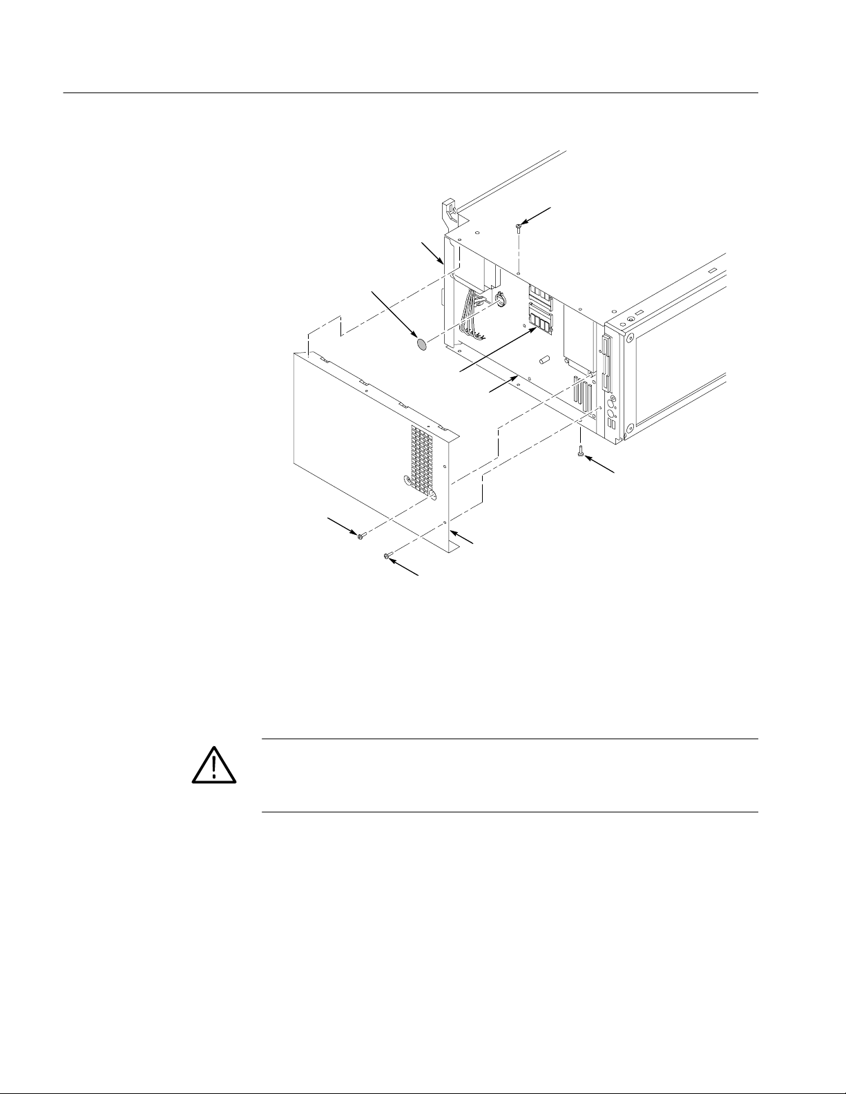
Removal and Installation Procedures
Remove screws (3)
Rear panel
Battery
RAM SIMMs
Controller board
Remove screws (3)
Main Memory
Battery
Remove
screws (2)
Controller cover
Remove screws (2)
Figure 6- 19: Accessing the internal parts
Refer to Figure 6--19 and locate the SODIMM (RAM) module on the controller
board. To remove the memory, press outward on the clips holding each SODIMM module to the controller board, and then lift off the module board.
CAUTION. SODIMM modules must have gold plated contacts.
Use of SODIMM modules that do not have gold plated contacts will result in
eventual failure of the SODIMM module.
To install the memory, insert the new SODIMM module. Press down gently until
the clips that hold the modules to the controller board snap into place.
Refer to Figure 6--19 and locate the 3 V lithium battery on the controller board.
Remove the battery from the clip by using a small tool and prying the battery
until it pops out of the clip.
6- 36
TLA715 Dual Monitor Portable Mainframe Service Manual
Page 99

Controller Board
Removal and Installation Procedures
You will need a screwdriver with a size T-15 Torx tip to perform this procedure.
Removal
Installation
Refer to Figure 6--20 and complete the following steps to remove the controller
board from the mainframe:
1. Detach the four ribbon cables located near the bottom front corner of the
controller board.
2. Remove the center screw from the controller board.
3. Remove the two screws securing the controller board to the chassis at the
back panel.
4. Pull firmly on the rear panel until the controller board disconnects from the
backplane board connectors.
Complete the following steps to reinstall the controller board:
1. Reposition the controller board, and then push firmly on the backplane bus
connector until the board is fully seated in the connectors on the backplane
board.
2. Insert the center screw into the controller board.
3. Insert the two screws securing the controller board to the chassis at the back
panel.
CAUTION. There are no guides on the ribbon cable connectors. When you
reattach the cables, make sure that you center the cable connectors in their
respective sockets on the controller board. If you install the connectors off by one
pin, you will damage the instrument when you power up the instrument.
4. Reattach the four cables located near the bottom front corner of the controller
board.
5. Reposition the cover by sliding it back and under the edge of the rear panel.
6. Install the remaining T-15 screws that hold the cover in place.
7. Reinstall the top, bottom, and left side covers
8. Reinstall the trim ring.
TLA715 Dual Monitor Portable Mainframe Service Manual
6- 37
Page 100

Removal and Installation Procedures
Rear panel
Power connectors
Remove
screws (3)
Controller board
Backplane Board
Removal
Figure 6- 20: Removing the controller board
You will need a screwdriver with a size T-15 Torx tip to perform this procedure.
Refer to Figure 6--21 and complete the following steps to remove the backplane
board from the chassis:
1. Remove the controller board.
2. Remove the eight remaining screws that secure the backplane board to the
chassis.
3. Pull on the edges of the board nearest the front and rear surfaces of the
mainframe to remove the backplane board.
4. Detach fan cable.
6- 38
TLA715 Dual Monitor Portable Mainframe Service Manual
 Loading...