

Page 1

Service Manual
TLA 711
Color Benchtop Chassis
070-9773-00
Warning
The servicing instructions are for use by qualified
personnel only. To avoid personal injury, do not
perform any servicing unless you are qualified to
do so. Refer to all safety summaries prior to
performing service.
Page 2

Copyright T ektronix, Inc. All rights reserved.
T ektronix products are covered by U.S. and foreign patents, issued and pending. Information in this publication supercedes
that in all previously published material. Specifications and price change privileges reserved.
Printed in the U.S.A.
T ektronix, Inc., P.O. Box 1000, Wilsonville, OR 97070–1000
TEKTRONIX and TEK are registered trademarks of T ektronix, Inc.
Page 3

WARRANTY
T ektronix warrants that the products that it manufactures and sells will be free from defects in materials and workmanship
for a period of one (1) year from the date of shipment. If a product proves defective during this warranty period, T ektronix,
at its option, either will repair the defective product without charge for parts and labor, or will provide a replacement in
exchange for the defective product.
In order to obtain service under this warranty, Customer must notify Tektronix of the defect before the expiration of the
warranty period and make suitable arrangements for the performance of service. Customer shall be responsible for
packaging and shipping the defective product to the service center designated by T ektronix, with shipping charges prepaid.
T ektronix shall pay for the return of the product to Customer if the shipment is to a location within the country in which the
T ektronix service center is located. Customer shall be responsible for paying all shipping charges, duties, taxes, and any
other charges for products returned to any other locations.
This warranty shall not apply to any defect, failure or damage caused by improper use or improper or inadequate
maintenance and care. T ektronix shall not be obligated to furnish service under this warranty a) to repair damage resulting
from attempts by personnel other than T ektronix representatives to install, repair or service the product; b) to repair
damage resulting from improper use or connection to incompatible equipment; c) to repair any damage or malfunction
caused by the use of non-T ektronix supplies; or d) to service a product that has been modified or integrated with other
products when the effect of such modification or integration increases the time or difficulty of servicing the product.
THIS WARRANTY IS GIVEN BY TEKTRONIX IN LIEU OF ANY OTHER WARRANTIES, EXPRESS OR
IMPLIED. TEKTRONIX AND ITS VENDORS DISCLAIM ANY IMPLIED WARRANTIES OF
MERCHANTABILITY OR FITNESS FOR A P ARTICULAR PURPOSE. TEKTRONIX’ RESPONSIBILITY T O
REP AIR OR REPLACE DEFECTIVE PRODUCTS IS THE SOLE AND EXCLUSIVE REMEDY PROVIDED TO
THE CUSTOMER FOR BREACH OF THIS WARRANTY. TEKTRONIX AND ITS VENDORS WILL NOT BE
LIABLE FOR ANY INDIRECT , SPECIAL, INCIDENTAL, OR CONSEQUENTIAL DAMAGES IRRESPECTIVE
OF WHETHER TEKTRONIX OR THE VENDOR HAS ADVANCE NOTICE OF THE POSSIBILITY OF SUCH
DAMAGES.
Page 4

TEKTRONIX SERVICE OPTIONS
T ektronix offers the following service options. These options are modular, flexible, and easy to order with your instrument. Designed to ease installation and start up, to support tracking of calibration to requirements of ISO9000, and
to provide for extended repair coverage, these options help fix your long-term maintenance costs and eliminate unplanned expenditures. And these options can be converted from service at T ektronix service depots to service on-site
(see Option S3), which helps keep downtime to a minimum.
Product installation service
1
Option IN Provides initial installation of the product and
familiarizes new users with some of its operation features
Three years of calibration services Option C3 Provides initial Certification on delivery, plus
two more annual calibrations from your service center
Test data Option D3 Provides test data on delivery and when annu-
al calibration services are provided (three total, requires Option C3)
Three years repair coverage Option R3 Provides three years of repair coverage for the
instrument, including displays and accessories
sold with the instrument
One year uplift to on–site service
1,2
Option S1 Converts the standard one year, “return to de-
pot” warranty to provide service on site for
one year
Three year uplift to on-site service
1,2
Option S3 Converts any C3, D3, and R3 options pur-
chased to on-site services for three years
Tektronix Service Options are available at the time you order your instrument. Contact your local Tektronix Sales
Office for more information.
1
Availability of installation and on-site services depends on the type of product and may vary by geography.
2
Uplift options are ordered with the mainframe products and cover individual modules.
Page 5

Table of Contents
Specifications
Operating Information
General Safety Summary v. . . . . . . . . . . . . . . . . . . . . . . . . . . . . . . . . . . .
Service Safety Summary vii. . . . . . . . . . . . . . . . . . . . . . . . . . . . . . . . . . . . .
Preface ix. . . . . . . . . . . . . . . . . . . . . . . . . . . . . . . . . . . . . . . . . . . . . . . . . . .
Manual Conventions x. . . . . . . . . . . . . . . . . . . . . . . . . . . . . . . . . . . . . . . . . . . . . .
Related Manuals xi. . . . . . . . . . . . . . . . . . . . . . . . . . . . . . . . . . . . . . . . . . . . . . . . . .
Introduction xiii. . . . . . . . . . . . . . . . . . . . . . . . . . . . . . . . . . . . . . . . . . . . . . .
Adjustment Interval xiii. . . . . . . . . . . . . . . . . . . . . . . . . . . . . . . . . . . . . . . . . . . . . . .
Strategy for Servicing xiii. . . . . . . . . . . . . . . . . . . . . . . . . . . . . . . . . . . . . . . . . . . . .
T ektronix Service Offerings xiv. . . . . . . . . . . . . . . . . . . . . . . . . . . . . . . . . . . . . . . . .
Contacting T ektronix xv. . . . . . . . . . . . . . . . . . . . . . . . . . . . . . . . . . . . . . . . . . . . . .
Product Description 1–1. . . . . . . . . . . . . . . . . . . . . . . . . . . . . . . . . . . . . . . . . . . . . . .
Characteristics T ables 1–3. . . . . . . . . . . . . . . . . . . . . . . . . . . . . . . . . . . . . . . . . . . . . .
Installation 2–1. . . . . . . . . . . . . . . . . . . . . . . . . . . . . . . . . . . . . . . . . . . . . . . . . . . . . .
Operating Information 2–1. . . . . . . . . . . . . . . . . . . . . . . . . . . . . . . . . . . . . . . . . . . . .
Selecting the Correct Power Cord and Fuse 2–3. . . . . . . . . . . . . . . . . . . . . . . . . . . .
Theory of Operation
Standard Chassis 3–1. . . . . . . . . . . . . . . . . . . . . . . . . . . . . . . . . . . . . . . . . . . . . . . . .
Performance Verification
Adjustment Procedures
Maintenance
Related Maintenance Procedures 6–1. . . . . . . . . . . . . . . . . . . . . . . . . . . . . . . . . . . . .
Preparation 6–2. . . . . . . . . . . . . . . . . . . . . . . . . . . . . . . . . . . . . . . . . . . . . . . . . . . . . .
Preventing ESD 6–2. . . . . . . . . . . . . . . . . . . . . . . . . . . . . . . . . . . . . . . . . . . . . . . . . .
Inspection and Cleaning 6–3. . . . . . . . . . . . . . . . . . . . . . . . . . . . . . . . . . . . . . . . . . . .
Removal and Installation Procedures 6–5. . . . . . . . . . . . . . . . . . . . . . . . . .
Preparation — Please Read 6–5. . . . . . . . . . . . . . . . . . . . . . . . . . . . . . . . . . . . . . . . .
List of Replaceable Parts 6–5. . . . . . . . . . . . . . . . . . . . . . . . . . . . . . . . . . . . . . . . . . .
Summary of Procedures 6–6. . . . . . . . . . . . . . . . . . . . . . . . . . . . . . . . . . . . . . . . . . . .
T ools Required 6–6. . . . . . . . . . . . . . . . . . . . . . . . . . . . . . . . . . . . . . . . . . . . . . . . . . .
Module Removal and Replacement 6–7. . . . . . . . . . . . . . . . . . . . . . . . . . . . . . . . . . .
Removing the Blower Assembly 6–7. . . . . . . . . . . . . . . . . . . . . . . . . . . . . . . . . . . . .
Removing the Monitor Board 6–11. . . . . . . . . . . . . . . . . . . . . . . . . . . . . . . . . . . . . . .
Removing the Power Supply 6–12. . . . . . . . . . . . . . . . . . . . . . . . . . . . . . . . . . . . . . . .
Removing the Card Guides 6–14. . . . . . . . . . . . . . . . . . . . . . . . . . . . . . . . . . . . . . . . .
Removing the T emperature Sense Board 6–17. . . . . . . . . . . . . . . . . . . . . . . . . . . . . . .
Removing the Backplane 6–18. . . . . . . . . . . . . . . . . . . . . . . . . . . . . . . . . . . . . . . . . . .
TLA711 Benchtop Chassis Service Manual
i
Page 6

Table of Contents
Options
Electrical Parts List
Diagrams
Mechanical Parts List
Special Configuration Options 6–20. . . . . . . . . . . . . . . . . . . . . . . . . . . . . . . . . . . . . . .
Troubleshooting 6–23. . . . . . . . . . . . . . . . . . . . . . . . . . . . . . . . . . . . . . . . . . . .
Check for Common Problems 6–24. . . . . . . . . . . . . . . . . . . . . . . . . . . . . . . . . . . . . . .
Eliminate Other Problem Sources 6–25. . . . . . . . . . . . . . . . . . . . . . . . . . . . . . . . . . . .
Troubleshoot the Benchtop Chassis 6–25. . . . . . . . . . . . . . . . . . . . . . . . . . . . . . . . . . .
Overview of Procedures 6–29. . . . . . . . . . . . . . . . . . . . . . . . . . . . . . . . . . . . . . . . . . . .
Adjustment After Repair 6–29. . . . . . . . . . . . . . . . . . . . . . . . . . . . . . . . . . . . . . . . . . .
Repackaging Instructions 6–31. . . . . . . . . . . . . . . . . . . . . . . . . . . . . . . . . . . .
Packaging 6–31. . . . . . . . . . . . . . . . . . . . . . . . . . . . . . . . . . . . . . . . . . . . . . . . . . . . . . .
Storage 6–32. . . . . . . . . . . . . . . . . . . . . . . . . . . . . . . . . . . . . . . . . . . . . . . . . . . . . . . . .
Standard Accessories 10–1. . . . . . . . . . . . . . . . . . . . . . . . . . . . . . . . . . . . . . . . . . . . . .
Optional Accessories 10–3. . . . . . . . . . . . . . . . . . . . . . . . . . . . . . . . . . . . . . . . . . . . . .
Parts Ordering Information 10–3. . . . . . . . . . . . . . . . . . . . . . . . . . . . . . . . . . . . . . . . .
Common Replaceable Parts 10–5. . . . . . . . . . . . . . . . . . . . . . . . . . . . . . . . . . . . . . . . .
Using the Replaceable Parts List 10–6. . . . . . . . . . . . . . . . . . . . . . . . . . . . . . . . . . . . .
ii
TLA711 Benchtop Chassis Service Manual
Page 7

List of Figures
Table of Contents
Figure 1–1: Front view and side view of standard Benchtop Chassis 1–10
Figure 1–2: Front view and side view of Benchtop Chassis with
Rackmount Option 1–10. . . . . . . . . . . . . . . . . . . . . . . . . . . . . . . . . . . . . .
Figure 2–1: Front view of the standard Benchtop Chassis 2–1. . . . . . . . .
Figure 2–2: Rear view of the standard Benchtop Chassis 2–2. . . . . . . . . .
Figure 2–3: Power cord identification chart 2–3. . . . . . . . . . . . . . . . . . . . .
Figure 3–1: Chassis block diagram 3–2. . . . . . . . . . . . . . . . . . . . . . . . . . . .
Figure 3–2: Passive monitor connector 3–4. . . . . . . . . . . . . . . . . . . . . . . . .
Figure 6–1: Location of blower assembly screws on the rear of
the chassis 6–8. . . . . . . . . . . . . . . . . . . . . . . . . . . . . . . . . . . . . . . . . . . . .
Figure 6–2: Removing the blower assembly 6–9. . . . . . . . . . . . . . . . . . . . .
Figure 6–3: Removing the blower 6–10. . . . . . . . . . . . . . . . . . . . . . . . . . . . .
Figure 6–4: Removing the Monitor board 6–11. . . . . . . . . . . . . . . . . . . . . .
Figure 6–5: Removing the power supply 6–12. . . . . . . . . . . . . . . . . . . . . . . .
Figure 6–6: Removing the Power Supply Interface board 6–13. . . . . . . . .
Figure 6–7: Removing the top and bottom card guides 6–15. . . . . . . . . . . .
Figure 6–8: Replacing the top and bottom nut rails 6–16. . . . . . . . . . . . . .
Figure 6–9: Removing the Temperature Sense board 6–17. . . . . . . . . . . . .
Figure 6–10: Removing the Backplane 6–19. . . . . . . . . . . . . . . . . . . . . . . . .
Figure 6–11: Power switch connectors 6–21. . . . . . . . . . . . . . . . . . . . . . . . .
Figure 6–12: 8/10 and 13/15 jumper location on the
Monitor board 6–22. . . . . . . . . . . . . . . . . . . . . . . . . . . . . . . . . . . . . . . . . .
Figure 6–13: Primary troubleshooting procedure 6–27. . . . . . . . . . . . . . . .
Figure 6–14: Rear-panel connector diagram 6–28. . . . . . . . . . . . . . . . . . . .
Figure 9–1: Interconnections 9–1. . . . . . . . . . . . . . . . . . . . . . . . . . . . . . . . .
Figure 9–2: Chassis block diagram 9–2. . . . . . . . . . . . . . . . . . . . . . . . . . . .
Figure 10–1: Cabinet and chassis assembly 10–9. . . . . . . . . . . . . . . . . . . . .
Figure 10–2: Circuit boards and chassis parts 10–11. . . . . . . . . . . . . . . . . . .
Figure 10–3: Power supply and blower assembly 10–13. . . . . . . . . . . . . . . .
Figure 10–4: 1R rackmount assembly 10–15. . . . . . . . . . . . . . . . . . . . . . . . . .
TLA711 Benchtop Chassis Service Manual
iii
Page 8

Table of Contents
List of Tables
Table 1–1: AC power source 1–3. . . . . . . . . . . . . . . . . . . . . . . . . . . . . . . . .
Table 1–2: Secondary power 1–4. . . . . . . . . . . . . . . . . . . . . . . . . . . . . . . . . .
Table 1–3: Cooling 1–5. . . . . . . . . . . . . . . . . . . . . . . . . . . . . . . . . . . . . . . . .
Table 1–4: Safety 1–6. . . . . . . . . . . . . . . . . . . . . . . . . . . . . . . . . . . . . . . . . . .
Table 1–5: Environmental 1–7. . . . . . . . . . . . . . . . . . . . . . . . . . . . . . . . . . .
Table 1–6: Electromagnetic compatibility (EMC) 1–8. . . . . . . . . . . . . . . .
Table 1–7: Mechanical 1–9. . . . . . . . . . . . . . . . . . . . . . . . . . . . . . . . . . . . . .
Table 3–1: Passive monitor connector pinouts 3–4. . . . . . . . . . . . . . . . . . .
Table 6–1: Tools required for parts replacement 6–6. . . . . . . . . . . . . . . . .
Table 6–2: Failure symptoms and possible causes 6–24. . . . . . . . . . . . . . . .
Table 6–3: Troubleshooting overview 6–29. . . . . . . . . . . . . . . . . . . . . . . . . .
Table 7–1: Options 7–1. . . . . . . . . . . . . . . . . . . . . . . . . . . . . . . . . . . . . . . . .
Table 10–1: Standard accessories 10–1. . . . . . . . . . . . . . . . . . . . . . . . . . . . .
Table 10–2: Power cord identification 10–2. . . . . . . . . . . . . . . . . . . . . . . . .
Table 10–3: Optional accessories 10–3. . . . . . . . . . . . . . . . . . . . . . . . . . . . . .
Table 10–4: Common replaceable parts 10–5. . . . . . . . . . . . . . . . . . . . . . . .
Table 10–5: Parts lists column descriptions 10–6. . . . . . . . . . . . . . . . . . . . .
iv
TLA711 Benchtop Chassis Service Manual
Page 9

General Safety Summary
Review the following safety precautions to avoid injury and prevent damage to
this product or any products connected to it. To avoid potential hazards, use this
product only as specified.
Only qualified personnel should perform service procedures.
While using this product, you may need to access other parts of the system. Read
the General Safety Summary in other system manuals for warnings and cautions
related to operating the system.
To Avoid Fire or
Personal Injury
Use Proper Power Cord. Use only the power cord specified for this product and
certified for the country of use.
Connect and Disconnect Properly . Do not connect or disconnect probes or test
leads while they are connected to a voltage source.
Ground the Product. This product is grounded through the grounding conductor
of the power cord. To avoid electric shock, the grounding conductor must be
connected to earth ground. Before making connections to the input or output
terminals of the product, ensure that the product is properly grounded.
Observe All Terminal Ratings. To avoid fire or shock hazard, observe all ratings
and marking on the product. Consult the product manual for further ratings
information before making connections to the product.
The common terminal is at ground potential. Do not connect the common
terminal to elevated voltages.
Do not apply a potential to any terminal, including the common terminal, that
exceeds the maximum rating of that terminal.
Do Not Operate Without Covers. Do not operate this product with covers or panels
removed.
Use Proper Fuse. Use only the fuse type and rating specified for this product.
Avoid Exposed Circuitry. Do not touch exposed connections and components
when power is present.
Do Not Operate With Suspected Failures. If you suspect there is damage to this
product, have it inspected by qualified service personnel.
Do Not Operate in Wet/Damp Conditions.
Do Not Operate in an Explosive Atmosphere.
Keep Product Surfaces Clean and Dry .
TLA711 Benchtop Chassis Service Manual
v
Page 10

General Safety Summary
Provide Proper Ventilation. Refer to the manual’s installation instructions for
details on installing the product so it has proper ventilation.
Symbols and Terms
T erms in this Manual. These terms may appear in this manual:
WARNING. Warning statements identify conditions or practices that could result
in injury or loss of life.
CAUTION. Caution statements identify conditions or practices that could result in
damage to this product or other property.
T erms on the Product. These terms may appear on the product:
DANGER indicates an injury hazard immediately accessible as you read the
marking.
WARNING indicates an injury hazard not immediately accessible as you read the
marking.
CAUTION indicates a hazard to property including the product.
Symbols on the Product. The following symbols may appear on the product:
vi
WARNING
High Voltage
Protective Ground
(Earth) T erminal
CAUTION
Refer to Manual
Double
Insulated
TLA711 Benchtop Chassis Service Manual
Page 11

Service Safety Summary
Only qualified personnel should perform service procedures. Read this Service
Safety Summary and the General Safety Summary before performing any service
procedures.
Do Not Service Alone. Do not perform internal service or adjustments of this
product unless another person capable of rendering first aid and resuscitation is
present.
Disconnect Power. To avoid electric shock, disconnect the main power by means
of the power cord or, if provided, the power switch.
Use Caution When Servicing the CRT. To avoid electric shock or injury, use
extreme caution when handling the CRT. Only qualified personnel familiar with
CRT servicing procedures and precautions should remove or install the CRT.
CRTs retain hazardous voltages for long periods of time after power is turned off.
Before attempting any servicing, discharge the CRT by shorting the anode to
chassis ground. When discharging the CRT, connect the discharge path to ground
and then the anode. Rough handling may cause the CRT to implode. Do not nick
or scratch the glass or subject it to undue pressure when removing or installing it.
When handling the CRT, wear safety goggles and heavy gloves for protection.
Use Care When Servicing With Power On. Dangerous voltages or currents may
exist in this product. Disconnect power, remove battery (if applicable), and
disconnect test leads before removing protective panels, soldering, or replacing
components.
To avoid electric shock, do not touch exposed connections.
X-Radiation. To avoid x-radiation exposure, do not modify or otherwise alter the
high-voltage circuitry or the CRT enclosure. X-ray emissions generated within
this product have been sufficiently shielded.
TLA711 Benchtop Chassis Service Manual
vii
Page 12

Preface
Manual Structure
This is the service manual for the TLA711 Benchtop Chassis. Read this preface
to learn how this manual is structured, what conventions it uses, and where you
can find other information related servicing this product. Read the Introduction,
which follows this preface, for safety and other important background information needed before using this manual for servicing this product.
The TLA 711 Benchtop Chassis Service Manual is divided into chapters, which
are made up of related subordinate topics. These topics can be cross referenced
as sections.
Be sure to read the introductions to all procedures. These introductions provide
important information needed to do the service correctly, safely, and efficiently.
A brief description of each chapter follows:
H Specifications contains a product description of the Benchtop Chassis and
tables of the characteristics and descriptions that apply to it.
H Operating Information includes basic installation and operating instructions
at the level needed to safely operate and service the Benchtop Chassis. For
complete installation and configuration procedures, refer to the Installation
Manual. Instructions for shipping the module are also found in this chapter.
H Theory of Operation contains circuit descriptions that support general service
to the replaceable part level.
H Performance Verification refers you to the TLA 700 Series Performance
Verification and Adjustment Technical Reference Manual that contains the
performance verification procedures for the Benchtop Chassis and for other
major components in the TLA 700 Series Logic Analyzer.
H Adjustment Procedures refer you to the TLA 700 Series Performance
Verification and Adjustment Technical Reference Manual that contains the
adjustment procedures for the Benchtop Chassis and for other major
components in the TLA 700 Series Logic Analyzer.
H Maintenance contains information and procedures for doing preventive and
corrective maintenance on the Benchtop Chassis. Included are instructions
for cleaning, for removal and installation of replaceable parts, and for
troubleshooting.
TLA711 Benchtop Chassis Service Manual
ix
Page 13

Preface
Manual Conventions
H Options contains information on the factory-installed options that may be
available for the Benchtop Chassis.
H Diagrams contains a block diagram and an interconnection diagram useful
for isolating failed circuit boards or assemblies.
H Mechanical Parts List includes a table of all replaceable parts, their
descriptions, and their Tektronix part numbers.
This manual uses certain conventions that you should become familiar with
before attempting service.
Modules
Replaceable Parts
Safety
Throughout this manual, the term module refers to a TLA 700 Series Logic
Analyzer or DSO unit that mounts inside a TLA 700 Series Portable or Benchtop
Chassis. A module is composed of circuit cards, interconnecting cables, and a
user-accessible front panel.
This manual refers to any field-replaceable assembly or mechanical part
specifically by its name or generically as a replaceable part. In general, a
replaceable part is any circuit board or assembly, such as the hard disk drive, or a
mechanical part, such as the I/O port connectors, that is listed in the replaceable
parts list of Chapter 10. Also, see Strategy for Servicing on page xiii.
Symbols and terms related to safety appear in the Service Safety Summary found
at the beginning of this manual.
x
TLA711 Benchtop Chassis Service Manual
Page 14

Related Manuals
The following manuals are available as part of the TLA 700 Series Logic
Analyzer documentation set. See Standard Accessories on page 10–1 and
Optional Accessories on page 10–17 for part numbers.
The procedures and information in this manual assumes that service personnel
have access to all manuals listed in the following table.
Manual Name Description Service Use
Preface
The TLA 700 Series Installation Manual Provides the basic installation instructions
for the TLA 700 Series Logic Analyzer.
The TLA 700 Series Performance Verifica-
tion and Adjustment T echnical Reference
Manual
The TLA 700 Series User Manual and TLA
700 Online Help
The TLA 711 Color Benchtop Controller
Service Manual
The TLA 704 Color Portable Mainframe
Service Manual
The TLA 7Lx/TLA 7Mx Logic Analyzer
Service Manual
The TLA Dx/TLA 7Ex Digitizing Oscilloscope Service Manual
Provides performance verification, certification, and adjustment procedures for the
TLA 700 Series Logic Analyzer.
Provides operating information on the
TLA 700 Series Logic Analyzer.
Provides service information for the slot 0
controller in the benchtop chassis.
Provides service information for the portable
mainframe.
Provides service information for the logic
analyzer modules.
Provides service information for the
digitizing oscilloscope modules.
Installation and removal of DSO, Logic
Analyzer, and Benchtop-Controller Modules
Reinstallation of Windows 95 and TLA 700
software
Replacing individual podlet cables in the
logic analyzer probes
Reformatting hard disk
Performing periodic or after-repair functional
or performance verifications
Performing periodic or after-repair adjust-
ment
Augments operating information found in
chapter 2 of this manual
Isolating and correcting failures in the
benchtop controller
Isolating and correcting failures in the
portable mainframe
Isolating and correcting failures in the logic
analyzer module
Isolating and correcting failures in the DSO
module
The TLA 7QS Training Manual Provides examples of using the TLA
QuickStart training board with TLA 700
Series Logic Analyzers.
The TLA 7QS Technical Reference Manual Provides service information and technical
information for the TLA QuickStart Training
board.
TLA711 Benchtop Chassis Service Manual
Used for training on operation of TLA 700
Series Logic Analyzer.
Servicing the TLA Quickstart Training board
only .
xi
Page 15

Introduction
Adjustment Interval
This manual contains information needed to properly service the Benchtop
Chassis This introduction contains information critical to safe and effective
servicing.
To prevent personal injury or damage to the Benchtop Chassis, consider the
following requirements before attempting service:
H The procedures in this manual should be performed only by a qualified
service person.
H Read the General Safety Summary and Service Safety Summary found at the
beginning of this manual.
H Read the Preface beginning on page ix.
H Read Operating Information beginning on page 2–1.
When using this manual for servicing, be sure to follow all warnings, cautions,
and notes.
Strategy for Servicing
There are no adjustments or certifiable parameters for the TLA711 Benchtop
Chassis. Refer to the TLA 711 Color Benchtop Controller Service Manual for
more information on adjustment and certification of the controller.
This manual supports and contains all the information needed for periodic
maintenance of the Benchtop Chassis. (Examples of such information are
procedures for fault isolation of a failed circuit board or assembly and for
removal and replacement of same.)
This manual also supports and contains information for corrective maintenance
of this product:
H supports isolation of faults to the failed circuit board or assembly level
shown in the replaceable parts list of Chapter 10
H supports removal and replacement of those boards or assemblies
H supports removal and replacement of fuses, knobs, chassis, and other
mechanical parts listed in the replaceable parts list
This manual does not support component-level fault isolation and replacement.
TLA711 Benchtop Chassis Service Manual
xiii
Page 16

Introduction
Service Offerings
Tektronix provides service to cover repair under warranty as well as other
services that are designed to meet your specific service needs.
Whether providing warranty repair service or any of the other services listed
below, Tektronix service technicians are well equipped to service the TLA 711
Benchtop Chassis. Tektronix technicians train on Tektronix products; they have
access to the latest information on improvements to the TLA 711 Benchtop
Chassis as well as the latest new product upgrades. Services are pr ovided at
Tektronix Services Centers and on-site at your facility, depending on your
location.
Warranty Repair Service
Calibration and Repair
Service
Tektronix warrants this product for one year from date of purchase. (The
warranty appears behind the title page in this manual.) Tektronix technicians
provide warranty service at most Tektronix service locations worldwide. The
Tektronix product catalog lists all service locations worldwide or you can visit us
on our Customer Services World Center web site at http://www.tek.com/Mea-
surement/Service. See our latest service offerings and contact us by email.
In addition to warranty repair, Tektronix Service offers calibration and other
services which provide cost-effective solutions to your service needs and qualitystandards compliance requirements. Our instruments are supported worldwide by
the leading-edge design, manufacturing, and service resources of Tektronix to
provide the best possible service.
The following services can be tailored to fit your requirements for calibration
and/or repair of the TLA 711 Benchtop Chassis.
Service Options. Tektronix Service Options can be selected at the time you
purchase your instrument. You select these options to provide the services that
best meet your service needs. These service options are listed on the Tektronix
Service Options page following the title page of this manual.
xiv
Service Agreements. If service options are not added to the instrument purchase,
then service agreements are available on an annual basis to provide calibration
services or post-warranty repair coverage for the TLA 711 Benchtop Chassis.
Service agreements may be customized to meet special turn-around time and/or
on-site requirements.
Service on Demand. Tektronix also offers calibration and repair services on a
“per-incident” basis that is available with standard prices for many products.
TLA711 Benchtop Chassis Service Manual
Page 17

Contacting Tektronix
Introduction
Self Service. Tektronix supports repair to the replaceable-part level by providing
for circuit board exchange.
Use this service to reduce down-time for repair by exchanging circuit boards for
remanufactured ones. Tektronix ships updated and tested exchange boards. Each
board comes with a 90-day service warranty.
For More Information. Contact your local Tektronix service center or sales
engineer for more information on any of the Calibration and Repair Services just
described.
Product
Support
Service
Support
For other
information
To write us Tektronix, Inc.
For application-oriented questions about a Tektronix measurement product, call toll free in North America:
1-800-TEK-WIDE (1-800-835-9433 ext. 2400)
6:00 a.m. – 5:00 p.m. Pacific time
Or contact us by e-mail:
tm_app_supp@tek.com
For product support outside of North America, contact your
local Tektronix distributor or sales office.
Contact your local Tektronix distributor or sales office. Or visit
our web site for a listing of worldwide service locations.
http://www.tek.com
In North America:
1-800-TEK-WIDE (1-800-835-9433)
An operator will direct your call.
P.O. Box 1000
Wilsonville, OR 97070-1000
TLA711 Benchtop Chassis Service Manual
xv
Page 18

Specifications
Product Description
This chapter provides a general description of the Benchtop Chassis and a list of
specifications under Characteristics Tables beginning on page 1–3.
The Benchtop Chassis is designed to be used as part of a TLA 700 Series Logic
Analyzer. It is an intelligent, 13-slot chassis with the following features:
H High output power supply
H Intelligent cooling for installed modules
H High quality auto-configurable backplane
H Optional adjustable rackmounts
Standard features are explained in more detail in the following paragraphs. Refer
to the Options chapter for a description of optional features.
Power Supply
Intelligent Cooling
The Benchtop Chassis provides voltages at levels sufficient for the most
demanding TLA 700 Series applications. The power supply has a volt-ampere
capacity of 1660 VA with 872 watts usable by TLA 700 Series instrument
modules at any one time. The chassis accommodates exclusively digital
applications (using the logic analyzer module), exclusively analog applications
(using the DSO module), or combinations of both.
The power supply plugs directly into the rear of the chassis and has no cables to
disconnect. Because of this design, you can replace the power supply in less than
three minutes, keeping downtime to a minimum. The power supply automatically accommodates the appropriate input voltage and frequency; no mechanical
switch is required to select the correct line voltage.
The Benchtop Chassis provides optimal cooling for all installed modules. The
chassis uses an intelligent, adaptive cooling scheme to efficiently remove heat
while maintaining quiet operation. When you set the blower to variable speed
(default), the chassis automatically adjusts the blower speed to keep the
temperature rise above the modules to approximately 10° C, or less. Using a rear
panel switch, you can set the blower to full speed to provide maximum cooling
at all times.
TLA711 Benchtop Chassis Service Manual
1–1
Page 19

Specifications
Air is exhausted at the sides of the chassis allowing you to stack the chassis with
other rackmount equipment. You don’t have to to worry about restricting any
airflow out of the top of the chassis or creating a chimney effect.
Cooling is not wasted on empty slots. Card guides automatically direct air to
only those slots containing modules; empty slots are shut off. The chassis directs
airflow across each installed module from the bottom to the top of each slot.
Baffles balance the airflow from the front to back and across occupied slots in
the chassis.
You can replace the blower without disassembling the entire chassis.
Backplane
The Benchtop Chassis has an autoconfigurable, solid-state backplane that uses
electronic jumpering of the IACK and BUS GRANT signal lines. There are no
jumpers to move or install on the backplane. This results in a high quality
backplane that is ideal for automatic test environment systems that must be
reconfigured frequently.
Full differential distribution of the CLK10 signals provide a clean timing source
for your TLA 700 Series instruments.
1–2
TLA711 Benchtop Chassis Service Manual
Page 20

Characteristics Tables
Specifications
This section lists specifications for the Benchtop Chassis. All specifications are
warranted unless noted “typical.” Typical characteristics describe typical or
average performance and provide useful reference information. Specifications
marked with the n symbol are checked in the Performance Verification chapter.
T able 1–1: AC power source
Characteristic Description
Source Voltage 90–250 V
100–132 V
45–66 Hertz, continuous range CA T II
RMS,
RMS,
Maximum Power Consumption 1350 W line power
(The maximum power consumed by a fully loaded 13-slot
instrument)
Fuse Rating
(Current and voltage ratings and
type of fuse used to fuse the source
line voltage)
90 V – 132 VAC
(High-power/Low Line
(159-0379-00)
Operation
RMS
Safety: UL198G/CSA C22.2,
Size: 0.25 in × 1.25 in,
Style: Slow acting,
Rating: 20 A/250 V
103 V – 250 VAC
(159-0256-00)
Operation
RMS
Safety: UL198G/CSA C22.2,
Size: 0.25 in × 1.25 in,
Style: No. 59/Fast acting,
Rating: 15 A/250 V
207 V – 250 VAC
(159-0381-00)
Operation
RMS
Safety: IEC 127/sheet 1
Size: 5 mm × 20 mm,
Style: Sheet 1, Fast acting “F”, high-breaking capacity,
Rating: 6.3 A/250 V
360–440 Hertz, continuous range CA T II
Inrush Surge Current 70 A maximum
Steady State Input Current 15 A RMS maximum at 90 VAC
Power Factor Correction Yes
TLA711 Benchtop Chassis Service Manual
6.3 Amps RMS maximum at 207 V AC
RMS
RMS
1–3
Page 21
Specifications
T able 1–2: Secondary power
Characteristic Description
n DC Voltage Regulation
(Combined System, voltage avail-
able at each slot)
Voltage Vmin, Vnom, Vmax
+24 V 23.28 V , 24.24 V , 25.20 V
+12 V 11.64 V, 12.12 V, 12.60 V
+5 V
–2 V
–5.2 V
–12 V
–24 V –25.20 V, –24.24 V, –23.28 V
4.875 V , 5.063 V , 5.25 V
–2.1 V , –2.000 V ,–1.9 V
–5.46 V , –5.252 V ,–5.044 V
–12.60 V, –12.12 V, –11.64 V
1–4
TLA711 Benchtop Chassis Service Manual
Page 22

Specifications
T able 1–3: Cooling
Characteristic Description
Cooling System Forced air circulation system (positive pressurization)
Blower Speed Control Rear panel switch selects between full speed and variable
Slot Activation Installing a module activates the cooling for the corresponding
Delta Temperature Readout
Sensitivity
Temperature Sense Range –10° C to +90° C, Delta temperature ≤ 50° C
Clearance 2 in (50.8 mm), rear, top, and sides of chassis
utilizing a single low-noise centripetal (squirrel cage)
blower configuration with no removable filters.
speed. Slot exhaust temperature and ambient air
temperature are monitored such that a constant delta
temperature is maintained across the module with the
highest exit air temperature at the minimum operational
blower speed.
occupied slots by opening the air flow shutter mechanism.
Optimizes cooling efficiency by only applying airflow to
modules that are installed.
100 mV/° C with 0° C corresponding to 0 V output
TLA711 Benchtop Chassis Service Manual
1–5
Page 23

Specifications
T able 1–4: Safety
Characteristic Description
Safety Certification Conforms to, and is certified where appropriate to the
IEC Characteristics Installation Category II
following requirements:
Listed to UL3111-1 for Electrical Measuring and Test
Equipment,
Approved (cUL) to CAN/CSA–22.2 No. 1010.1 – 92 Safety
Requirements for Electrical Equipment for Measurement,
Control, and Laboratory Use, Part 1
Manufacturers declaration of conformity to EN 61010–1/A2
1995 “Safety Requirements for Electrical Equipment for
Measurement, Control and Laboratory Use.” Following the
directive 73/23/EEC
Pollution Degree 2
Safety Class I
1–6
TLA711 Benchtop Chassis Service Manual
Page 24
Specifications
T able 1–5: Environmental
Characteristic Description
Classification
Atmospherics
Temperature
Operating +5° C to 50° C, 15 ° C/hr max gradient, non-condensing
Nonoperating –20° C to 60° C, 15° C/hr max gradient, non-condensing
Relative Humidity
Operating 20% to 80% relative humidity, non-condensing.
Nonoperating 8% to 80% relative humidity, non-condensing.
Altitude
Operating To 10,000 ft. (3,048 m)
Nonoperating 40,000 ft. (12,190 m)
(derated 1° C per 1000 ft. above 5000 ft. altitude
Max wet bulb temperature: +29°C
(derates relative humidity to approximately 22% @ 50°C).
Max wet bulb temperature: +29° C
(derates relative humidity to ~55% @ 50°C).
(derated 1° C/1000 ft. (305m) above 5000 ft. (1524m)
altitude)
TLA711 Benchtop Chassis Service Manual
1–7
Page 25

Specifications
T able 1–6: Electromagnetic compatibility (EMC)
Characteristic Description
Emissions Emissions shall be within the limits specified by the
following requirements:
Enclosure: EN 55011 Class A limits for radiated emissions
AC Mains: EN 55011 Class A limits for conducted emissions
EN 60555-2 AC power line harmonic emissions
Immunity , Enclosure,
RF Electromagnetic Field
Immunity , Enclosure,
Electrostatic Discharge
Immunity, Fast Transients, Common Mode
No instrument failures when the instrument is subjected to
a 3 V/m electromagnetic field over the frequency range of
27 MHz to 500 MHz.
Up to 8 kV with no change to control settings or
impairment of normal operation.
No loss of stored data, change to control settings,
degradation of performance, or temporary loss of function
will occur when the system is subjected to the following
transients:
Port Peak Voltage Tr/Th Rep Frequency
(k/V) (ns) (k/Hz)
––––––––––––––––––––––––––––––––––––––––––––
Signal & 0.5 5/50 5
Control
AC Power 1 5/50 5
1–8
TLA711 Benchtop Chassis Service Manual
Page 26

Specifications
T able 1–7: Mechanical
Characteristic Description
Overall Dimensions (See Figure 1–1 for overall chassis dimensions)
Standard Chassis
Height (with feet) 14.25 in (362.0 mm)
Width 16.75 in (425.5 mm)
Depth 26.5 in (673.1 mm)
Chassis with Rackmount
Height 14.0 in (355.6 mm)
Width 18.9 in (480.1 mm)
Depth 29.4 in (746.7 mm) min to 34.4 in (873.8 mm) max
Weight
Minimum mainframe configuration with Benchtop Controller
and slot filler panels installed (5
dual wides and 1 single wide
Typical configuration: same as
as minimum above with the
addition of 2 TLA7x4 LA’ s and
1 TLA7x2 DSO at 5 lbs 10 oz’s
each, and removal of 3 slot
filler panels
Shipping weight: minimum
configuration with Benchtop
Controller module (only) and all
mainframe standard accessories (2 manuals, 5 dual wide, 1
single slot filler panels, power
cord, empty pouch, front cover,
keyboard, software, and cables
Shipping weight: fully configured instrument. Same as
minimum above with the addition of 3 LA’s (TLA7M1,
TLA7M2, and TLA7M3) and 2
DSO’s (TLA 7D1 and TLA7E1),
and all module standard accessories (probes, clips)
62 lbs 2 oz. (28.18 kg)
77 lbs 14 oz. (35.32 kg)
118 lb (53.52 kg)
175 lb (79.38 kg)
Rackmount kit adder 20 lbs (9.07 kg)
Module Size 13 plug-in slots
TLA711 Benchtop Chassis Service Manual
1–9
Page 27

Specifications
16.75 in
(425.5 mm)
14.25 in
(362.0 mm)
Figure 1–1: Front view and side view of standard Benchtop Chassis
18.9 in
(480.1 mm)
26.5 in
(673.1 mm)
29.4 in (746.7 mm) Min to
34.4 in (873.8 mm) Max
14.0 in
(355.6 mm)
Figure 1–2: Front view and side view of Benchtop Chassis with Rackmount Option
1–10
TLA711 Benchtop Chassis Service Manual
Page 28

Operating Information
This chapter contains information about operating the Benchtop Chassis. Refer
to the TLA 700 Series Installation Manual for information on how to install and
configure the Benchtop Chassis. For more detailed operating information, refer
to the TLA 700 Series Logic Analyzer User Manual (Tektronix part number
070-9775-XX) and in the online help.
Installation
Basic installation instructions are contained in the TLA 700 Series Installation
Manual.
Operating Information
Figure 2–1 and Figure 2–2 show front and rear views, respectively, of the
Benchtop Chassis. Chassis slots 2 through 11 are labeled on the top and bottom
of the chassis. Slots 0 and 1 are reserved for the dual-wide controller; all other
slots are available for any other TLA 700 Series modules.
On/Standby
switch
Figure 2–1: Front view of the standard Benchtop Chassis
TLA711 Benchtop Chassis Service Manual
2–1
Page 29
Operating Information
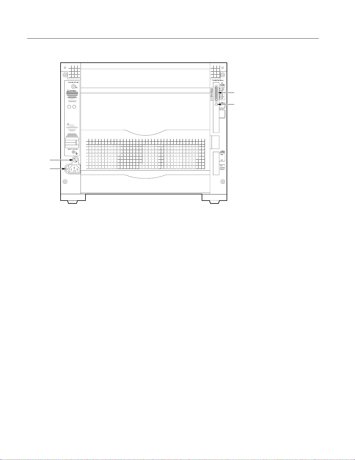
Fuse
AC Power
25-Pin PASSIVE
MONITOR connector
Fan speed switch
Figure 2–2: Rear view of the standard Benchtop Chassis
When you install a module with a front panel, shutters on the bottom of each slot
automatically open to provide cooling for the installed modules. The shutters
remain closed for empty slots so that airflow is directed only where it is needed.
On/Standby Switch
The On/Standby switch on the top-left corner of the front panel applies DC
voltages to the chassis. The switch is a momentary contact switch. The switch is
lighted when DC voltages are applied to the chassis. You can also remotely
control the chassis.
You can configure your chassis to bypass the On/Standby switch. (Refer to
Remote Power Switch Configuration on page 6–20 of the Maintenance chapter
for information on configuring the power switch.) In this configuration, the
On/Standby switch remains lighted while power is applied, but the switch itself
no longer controls the chassis.
AC Power Connector
The AC power connector is located on the bottom left side on the rear of the
chassis. The AC fuse holder is located just above the power connector.
2–2
TLA711 Benchtop Chassis Service Manual
Page 30
Operating Information
Chassis Ground Screw
The chassis ground screw (if installed) can be used to connect more than one
chassis to a common ground point.
Fan Speed Switch
The Fan Speed switch controls the speed of the system cooling fan. When the
switch is set to the VAR (variable) position, the chassis automatically controls
the speed of the fan depending on the air temperature and amount of cooling
required by the modules. When the switch is in the FULL position, the fans
operate at full speed.
Selecting the Correct Power Cord and Fuse
The Benchtop Chassis comes standard with two power cords and three fuses.
Before installing the chassis, you must determine the correct fuse and power cord
for your application. Use the following information to determine the appropriate
power cord and line fuse. This information is important to avoid overloading the
power distribution system and to comply with the National Electrical Code.
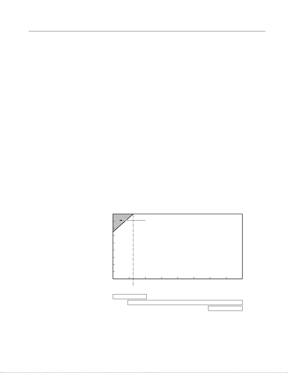
For card cage loads in the nonshaded region of Figure 2–3, use the power cord
with the 15 A plug (Tektronix part number 161-0213-XX) or the power cord
with the 20 A plug (Tektronix part number 161-0218-XX). For high card cage
loads combined with low input line voltages (shaded region), use only the power
cord with the 20 A plug.
Select the proper fuse based on the ranges shown in Figure 2–3.
Power Cord with 20A plug (NEMA 5–20P) ONLY!
Power Cord with 15A plug (NEMA 5–15P)
Power Cord with 20A plug (NEMA 5–20P)
130 150 170 190 210 230 250
Input Line Voltage (Volts AC)
6.3AF Fuse
Card Cage Power Consumption (Watts)
800
700
600
500
400
300
200
100
0
90 110
20AT Fuse
115
15AF Fuse
Figure 2–3: Power cord identification chart
TLA711 Benchtop Chassis Service Manual
2–3
Page 31

Theory of Operation
This section provides a brief overview of the theory of operation for the
Benchtop Chassis. Figure 3–1 shows a functional block diagram of the major
components.
Standard Chassis
The standard chassis contains the following major components:
H Power supply
H Power Supply Interface board
H Backplane
H Monitor board
H Temperature Sense board
H Blower assembly
Power Supply and Power
Supply Interface Board
Backplane
The power supply provides all voltages and currents to the chassis. The power
supply connects to the backplane at J1 and J2 through the Power Supply
Interface board.
The backplane (A4) provides all the connections to module slots 0 through 12 in
the chassis. It also has connections to all other circuit boards and modules in the
chassis.
The front panel On/Standby DC switch connects to one of two connectors at the
top of the backplane. When the switch is connected to J22, the switch controls
the power in the chassis. When the switch is connected to J23, the power-on
functions are controlled by an external source through the 25-pin connector on
the Monitor board. Although the switch still illuminates when power is applied
to the chassis, the on/off function of the switch is disabled. (Refer to Remote
Power Switch Configuration on page 6–20.)
The backplane connects to the Power Supply Interface board at J20 and J21. A
34-wide ribbon cable at 0J4 on the backplane connects to J16 on the Temperature
Sense board. Connectors 0J1, 0J2, and 0P3 carry instrument monitoring
information from the backplane to the Monitor board.
TLA711 Benchtop Chassis Service Manual
3–1
Page 32

Theory of Operation
3
25
J6
S2/3 J10 P9 S1 J7 J8
A3
Monitor Board
Passive Monitor
Fan Speed Switch
4
Blower
AC in
3
A1
Power Supply
Interface
Board
P1
J1
Power Supply
0J3 0P1 0P2
30 96
3
P20
P2
P21
J2
96
3
3
0J4 0P3 0J1 0J2
0P1 1P1 2P1 3P1 4P1 5P1 6P1 7P1 8P1 9P1 10P1 11P1 12P1
0P2
J20 J21
J23 J22
1P2 2P2 3P2 4P2 5P2 6P2 7P2 8P2 9P2 10P2
J16
3
J24
A4
Backplane
A2
Temperature Sense Board
Slot 0 Slot 1 Slot 2 Slot 3 Slot 4 Slot 5 Slot 6 Slot 7 Slot 8 Slot 9 Slot 10 Slot 11
11P2
12P2
Slot 12
On / Standby
Switch
Figure 3–1: Chassis block diagram
3–2
TLA711 Benchtop Chassis Service Manual
Page 33

Theory of Operation
Monitor Board
Temperature Sense Board
The Monitor board (A3) collects the monitoring information from the power
supply, blower, and Temperature Sense board and passes the information to the
25-pin D connector. The Monitor board connects directly to the backplane at 0J3,
0P1 and 0P2.
The 25-pin D Passive Monitor Connector lets you monitor the power supply
voltages, blower speed, and the maximum slot temperature rise within the
chassis. The connector also provides remote on and off capability and access to
the SYSRESET* and ACFAIL* signals. Figure 3–2 shows the pinouts of the
Passive Monitor Connector. Table 3–1 describes each of the pins and its
function.
WARNING. Do not connect an RS-232 cable to the 25-pin connector. The
connector is not an RS-232 connector. Connecting an RS-232 cable to the
connector can result in damage to the equipment.
The blower connects to the Monitor board at J7 (Fan2) and J8 (Fan1). The Fan
Speed switch (S1) lets you select either variable fan speed (VAR) or full speed
(FULL).
The Temperature Sense board (A2) monitors the temperatures for each slot
within the chassis. The Temperature Sense board connects to the backplane
through the ribbon cable at J16.
TLA711 Benchtop Chassis Service Manual
3–3
Page 34

Theory of Operation
Pin 1
Pin 25
Figure 3–2: Passive monitor connector
T able 3–1: Passive monitor connector pinouts
Pin Function Description
1 +5 VM +5 V for voltage monitoring
2 –12 VM –12 V for voltage monitoring
3 –24 VM –24 V for voltage monitoring
4 –2 VM –2 V for voltage monitoring
5 ON/ST Remote On/Standby Power Switch
6 +5 VC +5 V output for running external circuitry. 1 A max
7 +12 VC +12 V output for running external circuitry. 1 A max
8 +5 VB Input for +5 V standby current. 1 A max (pins 8 & 21)
9 GND Logic Ground
10 SYSR Backplane SYSRESET* signal (input or output). Use of this pin
requires adherence to VXI Specifications 1.4 (short extender cable,
etc.)
11 ∆T An analog output signal proportional to the maximum temperature
rise of the 13 modules (100 mV/°C rise)
1
3–4
TLA711 Benchtop Chassis Service Manual
Page 35

Theory of Operation
T able 3–1: Passive monitor connector pinouts (Cont.)
Pin DescriptionFunction
12 TACH1 A square wave output signal whose period is proportional to the
speed of fan #1
13 TACH2 A square wave output signal whose period is proportional to the
speed of fan #2 when a second fan is used. In the current Benchtop
Mainframe only a single blower is used
14 +12 VM +12 V for voltage monitoring
15 +24 VM +24 V for voltage monitoring
16 –5.2 VM –5.2 V for voltage monitoring
17 GND Logic Ground
18 GND Logic Ground
19 GND Logic Ground
20 GND Logic Ground
21 +5 VB Input for +5 V standby current. 1 A max (pins 8 & 21)
22 GND/T ACH3 Logic Ground OR a square wave output signal whose period is
proportional to the speed of fan #3 when a third fan is used. The
Benchtop Mainframe currently only utilizes a single blower so this
output will be grounded
1
23 ACFAIL Backplane ACFAIL* signal (input or output). Use of this pin requires
adherence to VXI Sys Specifications 1.4 (short extender cable, etc.)
24 GND/T ACH4 Logic Ground OR a square wave output signal whose period is
proportional to the speed of fan #4 when a fourth fan is used. The
Benchtop Mainframe currently only utilizes a single blower so this
output will be grounded
25 RSV Reserved as per the VXI Sys Specification 1.4
1 25-pin Sub-D connector provided on the upper left of the rear panel corner
(referenced from front of instrument) to provide access for power supply, temperature, and fan speed control monitoring.
TLA711 Benchtop Chassis Service Manual
3–5
Page 36

Performance Verification
The performance verification procedures for the TLA711 Benchtop Chassis are
located in the TLA 700 Series Performance Verification and Adjustment
Technical Reference Manual. There are no calibration (certification) procedures.
TLA711 Benchtop Chassis Service Manual
4–1
Page 37

Adjustment Procedures
There are no adjustment procedures for the TLA711 Benchtop Chassis.
TLA711 Benchtop Chassis Service Manual
5–1
Page 38

Maintenance
This chapter provides procedures for inspecting and cleaning the Benchtop
Chassis, removing and replacing internal chassis components, and isolating
problems to module levels.
H The Maintenance section provides general information on preventing
damage to internal circuit boards when doing maintenance and cleaning
external and internal parts.
H The Removal and Installation Procedures (page 6–5) provide procedures for
removing and installing circuit boards.
H Troubleshooting (page 6–23) provides information for isolating faulty circuit
boards and probes.
H Repackaging Instructions (page 6–31) provides packaging information for
shipment or storage.
You must accomplish instrument-level repairs by exchanging faulty modules
with known-good modules or parts. This chapter does not provide componentlevel procedures.
Related Maintenance Procedures
The following chapters contain information/procedures related to maintenance.
H The Operating Information chapter provides instructions for operating the
Benchtop Chassis in order to perform the maintenance procedures within this
manual.
H The Theory of Operation chapter contains a circuit description to the board,
or block, level.
H The Performance Verification chapter references the Performance Verifica-
tion and Adjustment Technical Reference manual. That manual contains tests
that may be useful in isolating problems by testing Benchtop Chassis
performance.
H The Diagrams chapter contains a block diagram using individual boards as
blocks and an interconnection diagram showing connections between the
circuit boards.
H The Mechanical Parts List chapter lists all field replaceable parts by part
number.
TLA711 Benchtop Chassis Service Manual
6–1
Page 39
Maintenance
Preparation
Preventing ESD
The TLA 700 Series Installation Manual may contain maintenance procedures
not included in this manual.
The information in this chapter is designed for use by qualified service personnel. Read the Safety Summary at the front of this manual before attempting any
procedures in this chapter. Refer to the Operating Basics chapter for information
on the location of controls, indicators, and connectors used with the chassis.
When performing any service which requires internal access to the mainframe
benchtop chassis, adhere to the following precautions to avoid damaging internal
circuit boards and their components due to electrostatic discharge (ESD).
CAUTION. Many components within the chassis are susceptible to staticdischarge damage. Service the chassis only in a static-free environment. Observe
standard handling precautions for static-sensitive devices while servicing the
chassis. Always wear a grounded wrist strap, or equivalent, while servicing the
chassis.
1. Minimize handling of static-sensitive circuit boards.
2. Transport and store static-sensitive circuit boards in their static protected
containers or on a metal rail. Label any package that contains static-sensitive
boards.
3. Discharge the static voltage from your body by wearing a grounded antistatic
wrist strap while handling these circuit boards. Do service of static-sensitive
circuit boards only at a static-free work station.
4. Nothing capable of generating or holding a static charge should be allowed
on the work station surface.
5. Handle circuit boards by the edges when possible.
6. Do not slide the circuit boards over any surface.
7. Avoid handling circuit boards in areas that have a floor or work-surface
covering capable of generating a static charge.
6–2
WARNING. To avoid electric shock, always power off the chassis and disconnect
the power cord before cleaning or servicing the chassis.
TLA711 Benchtop Chassis Service Manual
Page 40

Inspection and Cleaning
Maintenance
The chassis is inspected mechanically and electrically before shipment. It should
be free of marks or scratches and should meet or exceed all electrical specifications. To confirm this, inspect the chassis for physical damage incurred during
transit. Retain the chassis packaging in case shipment for repair is necessary. If
there is damage or deficiency, contact your local Tektronix representative.
Cleaning procedures consist of exterior and interior cleaning of the chassis and
cleaning the fan filter. Periodic cleaning reduces instrument breakdown and
increases reliability. Clean the chassis as needed, based on the operating
environment. Refer to your module documentation for information on cleaning
the individual TLA 700 Series modules.
Interior Cleaning
Exterior Cleaning
Use a dry, low-velocity stream of air to clean the interior of the chassis. Use a
soft-bristle brush for cleaning around components. If you must use a liquid for
minor interior cleaning, use a 75% isopropyl alcohol solution and rinse with
deionized water.
Clean the exterior surfaces of the chassis with a dry lint-free cloth or a softbristle brush. If any dirt remains, use a cloth or swab dipped in a 75% isopropyl
alcohol solution. Use a swab to clean narrow spaces around controls and
connectors. Do not use abrasive compounds on any part of the chassis.
CAUTION. Avoid getting moisture inside the chassis during exterior cleaning; use
just enough moisture to dampen the cloth or swab.
Do not wash the front-panel On/Standby switch. Cover the switch while washing
the chassis.
Use only deionized water when cleaning. Use a 75% isopropyl alcohol solution
as a cleanser and rinse with deionized water.
Do not use chemical cleaning agents; they may damage the chassis. Avoid
chemicals that contain benzene, toluene, xylene, acetone, or similar solvents.
TLA711 Benchtop Chassis Service Manual
6–3
Page 41
Removal and Installation Procedures
This section describes how to remove and install the major mechanical and
electrical modules. It provides the following information:
H List of Replaceable Parts on page 6–5 describes where to locate a list of
replaceable parts.
H Summary of Procedures on page 6–6 lists the procedures for removal and
installation of replaceable parts.
H Tools Required on page 6–6 describes the tools needed to perform the
procedures.
H Beginning with Removing the Blower Assembly on page 6–7, detailed
procedures describe the removal and installation of replaceable parts.
Preparation — Please Read
Please read the following warning statement. Then read the following general
instructions before removing a part.
WARNING. Before doing this or any other procedure in this manual, read the
General Safety Summary and Service Safety Summary found at the beginning of
this manual. Also, to prevent possible damage to electrical components, read
Preventing ESD on page 6–2.
Read the Summary of Procedures on page 6–6 to understand how the proce-
dures are grouped. Then read Tools Required on page 6–6 for a list of tools
needed to remove and install replaceable parts in the benchtop chassis.
List of Replaceable Parts
The Mechanical Parts List section provides a list of all replaceable parts.
TLA711 Benchtop Chassis Service Manual
6–5
Page 42

Removal and Installation Procedures
Summary of Procedures
The procedures are listed below in the order in which they appear in this section:
H Removing the Blower Assembly
H Removing the Monitor Board
H Removing the Power Supply
H Removing the Card Guides
H Removing the Top and Bottom Nut Rails
H Removing the Temperature Sense Board
H Removing the Backplane
Tools Required
Table 6–1 lists the tools needed to to disassemble the Benchtop Chassis:
T able 6–1: Tools required for parts replacement
Item Number Name Description
1 Flat Blade Screwdriver Small flat blade screwdriver
2 Cutters Diagonal cutters (for removing cable ties)
3 Screwdriver handle Accepts TorxR driver bits
8 T-15 Torx tip TorxR driver bit for T-15 size screw heads
9 T-20 Torx tip TorxR driver bit for T-20 size screw heads
10 Allen wrench A 3/32-inch Allen wrench (hex wrench)
11 Phillips screwdriver Phillips #1 screwdriver
6–6
TLA711 Benchtop Chassis Service Manual
Page 43

Module Removal and Replacement
The following procedures describe how to remove and replace Benchtop Chassis
modules. Refer to the parts lists and exploded view illustrations beginning on
page 10–8 for an overview of chassis assembly and disassembly.
Removing the Blower Assembly
To remove the blower assembly, refer to Figure 6–2 and Figure 6–3 while
performing the following steps:
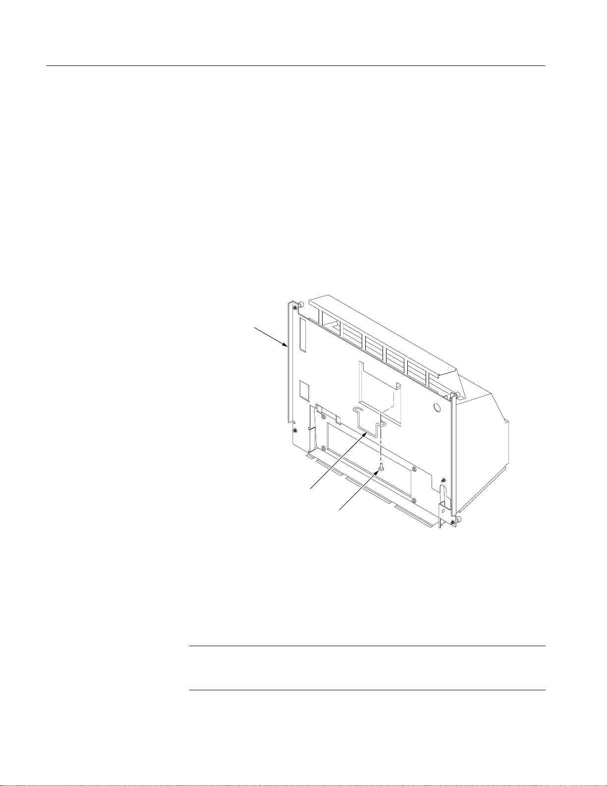
1. From the back of the chassis, loosen the five 8-32 captive screws including
the safety ground using a Phillips #1 screwdriver (refer to Figure 6–1 for the
screw locations).
2. Remove the Chassis Ground screw (if installed) using a T-20 tip.
3. Gently pivot the blower assembly outward from the chassis far enough to
access the blower cable on the right side of the chassis.
Removal and Installation Procedures
4. Unplug the blower cable and set the blower assembly aside on a clean
working surface.
5. To remove the blower, remove the ten 8-32 screws (with the Allen wrench)
holding the shroud part of the blower assembly to the chassis part of the
assembly. Set the shroud aside. There are three screws on each side and four
on the bottom. See Figure 6–3.
6. Remove the two sheet metal screws at the top of the blower.
7. Remove the four 8–32 screws that hold the blower to the chassis part of the
blower assembly.
8. For convenience, replace the two sheet metal screws from step 6 onto the top
of the blower.
NOTE. When reconnecting the blower cables to the chassis, verify that you
connect the blower cable to the proper connector
TLA711 Benchtop Chassis Service Manual
6–7
Page 44

Removal and Installation Procedures
8-32 Captive
screw
Chassis ground
(8-32 Screw
not installed)
Safety ground
8-32 captive
screw
8-32 captive
screw
Figure 6–1: Location of blower assembly screws on the rear of the chassis
8-32 captive
screw
8-32 captive
screw
6–8
TLA711 Benchtop Chassis Service Manual
Page 45

Power supply
Removal and Installation Procedures
Ledge
Blower assembly
Figure 6–2: Removing the blower assembly
Blower cable
TLA711 Benchtop Chassis Service Manual
6–9
Page 46

Removal and Installation Procedures
Shroud
Screws (4)
Blower assembly
Chassis
Screws (2)
Blower
Cable tie
Screws (4)
Screws (6)
Figure 6–3: Removing the blower
6–10
TLA711 Benchtop Chassis Service Manual
Page 47

Removing the Monitor Board
To remove the Monitor board, perform Removing the Blower Assembly and then
refer to Figure 6–4.
Grasp the cable tie loop and pull the monitor board until it comes loose from the
backplane. Then slide the board out of the right side of the chassis.
Monitor board
Removal and Installation Procedures
Cable tie loop
Figure 6–4: Removing the Monitor board
TLA711 Benchtop Chassis Service Manual
6–11
Page 48
Removal and Installation Procedures
Removing the Power Supply
To remove the power supply from the chassis, perform steps 1 through 4 of the
Removing the Blower Assembly procedure to remove the blower assembly.
Perform the Removing the Monitor Board procedure to remove the Monitor
board; then continue with the following steps:
1. Look in the recess in the chassis side of the blower assembly. You should
find in the recess the power supply handle and the two screws holding the
handle.
2. Remove the two screws and the power supply handle.
3. Reinstall the handle and the screws on the power supply. See Figure 6–5.
Blower assembly
(chassis side)
6–12
Power supply handle
Screws (2)
Figure 6–5: Removing the power supply
4. Using the handle on the power supply, firmly pull out the power supply from
the rear of the chassis.
5. Set the power supply assembly on a clean working surface.
NOTE. Step 6 is necessary only if you intend to replace the Power Supply
Interface board. This step is normally not necessary because the Power Supply
and the Power Supply Interface board can be replaced as a single unit.
TLA711 Benchtop Chassis Service Manual
Page 49

Removal and Installation Procedures
6. Refer to Figure 6–6 and remove the Power Supply Interface board from the
power supply module as shown.
8-32 Screws (4)
Power supply
interface board
Figure 6–6: Removing the Power Supply Interface board
TLA711 Benchtop Chassis Service Manual
6–13
Page 50

Removal and Installation Procedures
Removing the Card Guides
The card guides at the top and bottom of the chassis are very similar. The main
difference is that the bottom guides include the spring-loaded shutters to redirect
air into the chassis. The procedure for removing both guides is identical. Refer to
Figure 6–7 while performing the following steps:
1. Use a small flat blade screwdriver to pry up the tab of the card guide at the
2. Gently pull the card guide forward until it pops out of place.
3. Remove the card guide.
NOTE. The bottom card guides are replaced as a unit. These guides are not
intended to be disassembled.
To replace a card guide, slide the card guide towards the rear of the chassis and
allow the front of the card guide to snap into place.
front of the chassis being careful not to damage the card guide or the chassis.
6–14
TLA711 Benchtop Chassis Service Manual
Page 51

Gently pull the card guide
forward until it pops out of place.
Removal and Installation Procedures
Slide the card guides toward the rear of
the chassis and allow the front of the
card guide to snap into place.
Figure 6–7: Removing the top and bottom card guides
The nut rails at the top and the bottom of the front of the Benchtop Chassis allow
you to securely install the modules in the chassis by screwing the top and bottom
of the modules to the front of the chassis. Refer to Figure 6–8 to remove these
nut rails.
TLA711 Benchtop Chassis Service Manual
6–15
Page 52

Removal and Installation Procedures
1. Loosen all module retaining screws (it may be necessary to slide the modules
2. Remove the 12 screws holding the top cover to the chassis using a 3/32-inch
3. Slide the top cover of the chassis back far enough to expose the hole just
4. Slide the nut rail out of the hole on the side of chassis.
Replace the nut rail by sliding it back in the side of the chassis and pushing it
into place.
partially out of the chassis).
Allen wrench.
inside the top and bottom extrusions.
Top cover
Remove module
retaining screws.
Figure 6–8: Replacing the top and bottom nut rails
Nut rail
8-32 Screws (12)
Nut rail
6–16
TLA711 Benchtop Chassis Service Manual
Page 53

Removing the Temperature Sense Board
To remove the Temperature Sense board, remove the chassis cover and then
perform the following steps:
1. Disconnect the ribbon cable from the Temperature Sense board.
2. Refer to Figure 6–9 and gently pry back on each retainer holding the
Temperature Sense board in place.
3. Lift the board out of the holes at the top of the chassis being careful not to
damage any components on the circuit board.
Temperature
Sense board
Removal and Installation Procedures
Retainer
Figure 6–9: Removing the Temperature Sense board
Cable
TLA711 Benchtop Chassis Service Manual
6–17
Page 54

Removal and Installation Procedures
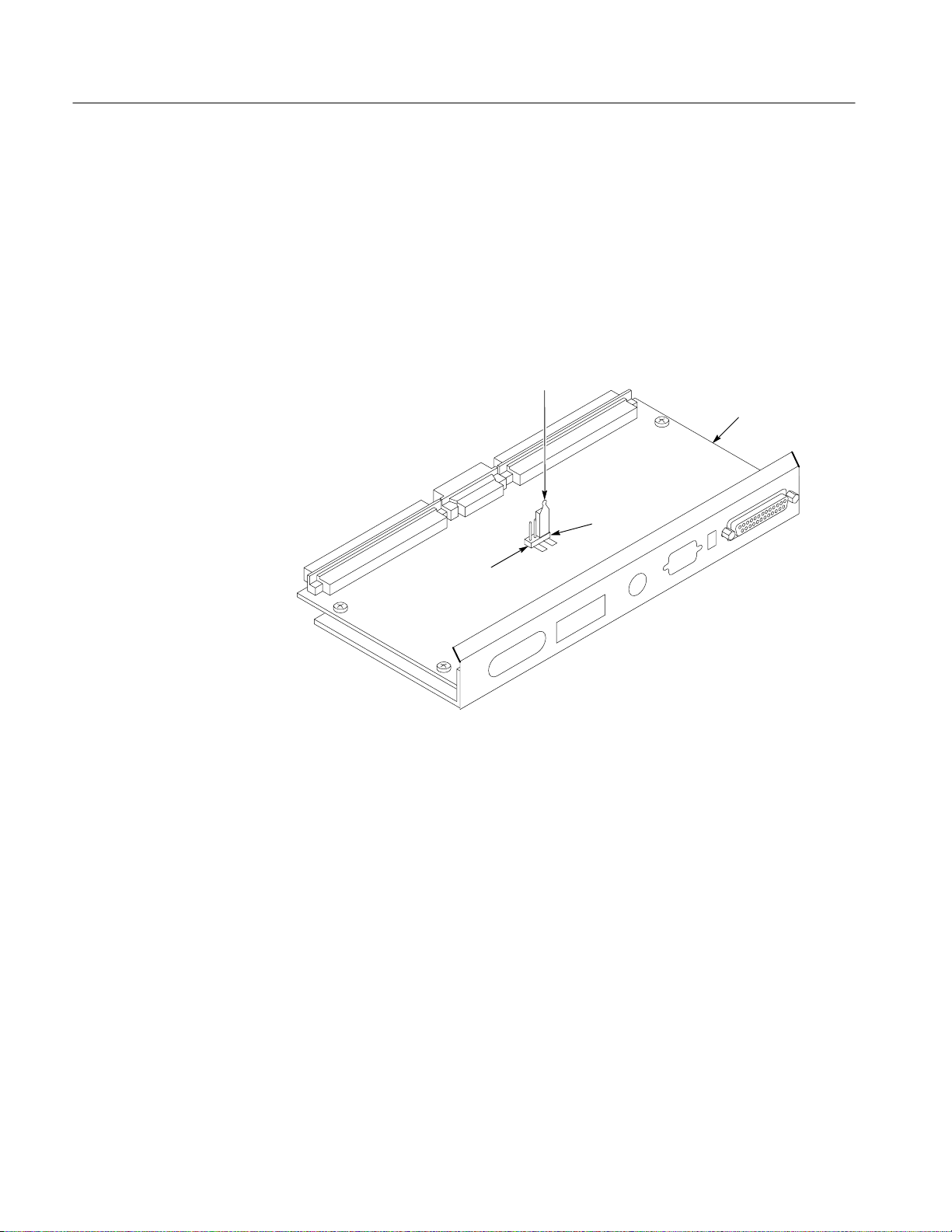
Removing the Backplane
To remove the backplane, perform the Removing the Blower Assembly, Removing
the Monitor Board, and Removing the Power Supply procedures. Refer to Figure
6–10 and then perform the following steps:
1. Remove the top cover of the chassis (see Figure 6–8, if necessary).
2. Disconnect the ribbon cable on the right side of the backplane.
NOTE. Before disconnecting the power switch cable, note which connector the
cable is connected to (J22, normally, or J23). Remember to reconnect the cable
to the correct connector.
3. Disconnect the power switch cable at J22 (or from J23) at the top of the
4. From the rear of the chassis, remove the five 6-32 screws on the top of the
backplane.
backplane, seven 6-32 screws from the center, and five 6-32 screws from the
bottom.
5. After removing all screws from the backplane, remove the backplane from
the chassis by sliding it out of the right side.
Install the backplane by reversing the disassembly procedure.
6–18
TLA711 Benchtop Chassis Service Manual
Page 55
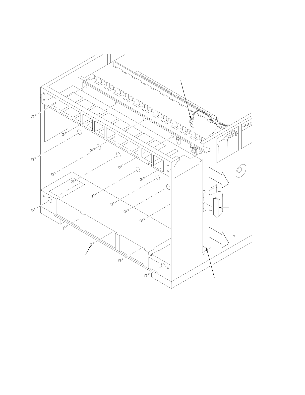
Power switch
connector
Removal and Installation Procedures
6-32 Screws (17)
Figure 6–10: Removing the Backplane
Ribbon
cable
(connector)
Backplane
TLA711 Benchtop Chassis Service Manual
6–19
Page 56

Removal and Installation Procedures
Special Configuration Options
This section contains information for configuring your Benchtop Chassis for
specific situations not documented earlier in this manual. These special
configuration options require you to disassemble parts of the chassis to access
jumpers or circuit boards. Refer to the Maintenance chapter for detailed
information on the assembly and disassembly procedures. You may also need to
refer to the exploded views in Mechanical Parts List.
The information in this section is intended for use by qualified service personnel.
Read the Safety Summary at the front of this manual and the static precautions on
page 6–2 before attempting any procedures in this appendix. Refer to Operating
Information for information on the location of controls, indicators, and connectors used with the chassis.
CAUTION. To avoid damage from high currents on the backplane, always power
off the chassis and disconnect the power cord before performing any of the
configuration procedures described in this section.
Remote Power Switch
Configuration
You can control the power-on function of the chassis using the front panel
On/Standby switch and from a remote momentary switch through the connections of the 25-pin rear panel connector. If you connect a remote switch to
pins 5 and 18 (return side) of the 25-pin connector, the remote switch and the
front-panel On/Standby switch control the power-on functions of the chassis.
You can also disable the front-panel switch and control the power-on functions
from the remote switch only. The backplane has two connectors that control the
power-on functions. If the front panel switch is connected to the backplane at
J22, the switch controls the power-on functions. If the switch is connected to
J23, the front panel switch is disabled, however, the light still illuminates when
the chassis is powered on. To configure the chassis to disable the front panel
On/Standby switch, perform the following steps:
6–20
TLA711 Benchtop Chassis Service Manual
Page 57

Removal and Installation Procedures
1. Disconnect the power cord from the chassis.
2. Remove the cover from the chassis.
3. Refer to Figure 6–11 and locate the two connectors at the top of the
backplane.
4. Disconnect the On/Standby switch cable at J22 and connect it to J23.
5. Replace the chassis cover.
6. Connect the momentary switch to pins 5 and 18 (return side) of the 25-pin
rear panel connector.
Power switch
connector
J22
J23
Figure 6–11: Power switch connectors
Backplane
TLA711 Benchtop Chassis Service Manual
6–21
Page 58
Removal and Installation Procedures
8°/10° and 13°/15° Jumper
on the Monitor board
Jumper J11 on the Monitor board (see Figure 6–12) allows you to further define
the temperature sensitivity of the Temperature Sense board. The jumper
determines the maximum allowable temperature rise in the chassis. The jumper
is shipped in the 8°/10° position.
You can move the jumper to the 13 ° /15° position if you do not expect a high
temperature rise in the modules or when the ambient room temperature will not
exceed the chassis maximum temperature. Moving the jumper to the 13°/15°
position reduces the fan speed and noise.
Jumper J11 location
Monitor board
8° / 10°
13° / 15°
6–22
Figure 6–12: 8°/10° and 13°/15° jumper location on the Monitor board
TLA711 Benchtop Chassis Service Manual
Page 59
Troubleshooting
WARNING. Before doing this or any other procedure in this manual, read the
General Safety Summary and Service Safety Summary found at the beginning of
this manual. Also, to prevent possible injury to service personnel or damage to
electrical components, read Preventing ESD on page 6–2.
This section contains information and procedures designed to help you isolate
faults to within the TLA 711 Benchtop Chassis. The process is as follows:
H Do Check for Common Problems on page 6–24 to eliminate easy to find
problems first.
H Do T roubleshoot the Benchtop Chassis, beginning on page 6–25, to isolate
locate the failed replaceable part within the module.
If you have replaced a faulty part found using these procedures, you must follow
any verification procedures identified in the TLA 700 Series Performance
Verification and Adjustment Technical Reference Manual.
Service Level
Required Documents
This section supports isolation of faults within the benchtop chassis to the
replaceable-part level that’s reflected in the replaceable parts list in Chapter 10.
In most cases, faults are isolated to circuit boards or assemblies, but not to
individual components on those boards. (See Strategy for Servicing on page xiii.)
Fault isolation is supported to the following replaceable parts:
H Blower
H Monitor board
H Power-supply or Power-supply Interface board
H Backplane board
H Fuses, cables, and other parts
Other TLA 700 manuals may be required to help you isolate faults; other
manuals and other sections in this manual contain instructions you will need to
complete repairs after locating a faulty part. See the table that follows.
TLA711 Benchtop Chassis Service Manual
6–23
Page 60

Troubleshooting
Manual or Section Purpose
TLA 700 Series Performance Verification and
Adjustment Procedures
TLA 700 Series Installation To remove and reinstall modules in mainframe;
Removal and Replacement Instructions (in this
manual)
Repealable Parts List (in this manual) To order replaceable parts
For a list of all manuals available for the TLA 700 Series Logic Analyzer family,
see see Related Manuals on page xi of the Preface to this manual.
Check for Common Problems
Use Table 6–2 to quickly isolate possible failures. The table lists problems
related to the benchtop chassis and possible causes. The list is not exhaustive,
but it may help you eliminate a problem that’s quick to fix, such as a blown fuse
or loose cable.
To check and adjust after circuit board or
assembly replacement
to reinstall Windows95 or TLA 700 Software
when required
To remove and reinstall failed replaceable
parts.
T able 6–2: Failure symptoms and possible causes
Symptom Possible Cause(s)
Mainframe does not
power on
Front-panel power switch
light comes on (mainframe
powers up), but the blower
will not operate
Monitor does not power on H Power connection faulty; check or substitute cord
Monitor display is blank H Adjust monitor controls for brightness and contrast
Mainframe does not boot H Non-system diskette or floppy in external drive; make sure
H Power connection faulty; check or substitute power cord
H Fuse blown; check line fuse
H Mainframe power supply failure; contact local Tektronix service
center
H Faulty blower cable
H Defective blower
H Faulty power supply
H Fuse blown; check line fuse
H Monitor power supply failure; contact local Tektronix service
center
H VGA cable connection faulty; check or substitute VGA cable
H Monitor failure; contact local Tektronix service center
computer is booting from hard drive
H Hard drive failure or corrupted files on hard drive; consult
manufacturer or product literature for service information
6–24
TLA711 Benchtop Chassis Service Manual
Page 61

T able 6–2: Failure symptoms and possible causes (Cont.)
Symptom Possible Cause(s)
Digitizing Oscilloscope or
Logic Analyzer module
and controller do not
power on
Controller does not
power on
Eliminate Other Problem Sources
Troubleshooting
H Modules not fully inserted; make sure front of module is flush
with front panel
H Mainframe not configured properly; consult manufacturer or
product literature for information
H Mainframe power supply failure; contact local Tektronix service
center
H Module not fully inserted; make sure front of module is flush
with front panel
H Mainframe not configured properly; consult manufacturer or
product literature for information
H Module failure; contact local Tektronix service center
The benchtop chassis is part of the TLA 700 Series Logic Analyzer, which
comprises modules installed in one of two mainframes (in this case, the TLA 711
Benchtop Chassis). If power-on diagnostics indicate that a TLA Controller, LA
or DSO module test failed, troubleshoot the module using the TLA service
manual for that module.
Troubleshoot the Benchtop Chassis
Follow the procedure in this section to identify the failed part within the
benchtop chassis.
Equipment Required
Preparation
The following test equipment is recommended to perform these procedures.
H Digital Voltmeter (Tektronix DM250 series digital voltmeter)
H Oscilloscope, 20 MHz BW, with 10x Probe with < 1-inch ground lead,
(Tektronix TDS400A or TDS500A series oscilloscope)
The fault isolation procedure requires that you:
H recognize if the front-panel Standby/On button lights up.
H recognize if the blower operates.
H measure voltages.
TLA711 Benchtop Chassis Service Manual
6–25
Page 62

Troubleshooting
Front-Panel Standby/On button. The Standby/On switch in the upper-right of the
front panel should light up when pressed. The blower in the rear should power
on.
Self Calibration. The Benchtop Chassis does not include self calibration.
Power On Diagnostics. The Benchtop Chassis does not include power on
diagnostics.
Extended Diagnostics. The Benchtop Chassis does not include extended
diagnostics.
Fault Isolation Procedure
Troubleshooting
Procedure
This section contains a troubleshooting chart on page 6–27 that will help you
locate faulty benchtop chassis replaceable parts:
To begin the procedure, simply turn on the chassis.
NOTE. Before replacing circuit boards, be sure to inspect all associated cables
and connectors for damage and proper installation.
If needed, use the Removal and Installation Procedures that begin on page 6–5
to replace the faulty circuit board.
This section contains a troubleshooting chart (see Figure 6–13) that will help
you locate faults within the chassis.
6–26
TLA711 Benchtop Chassis Service Manual
Page 63
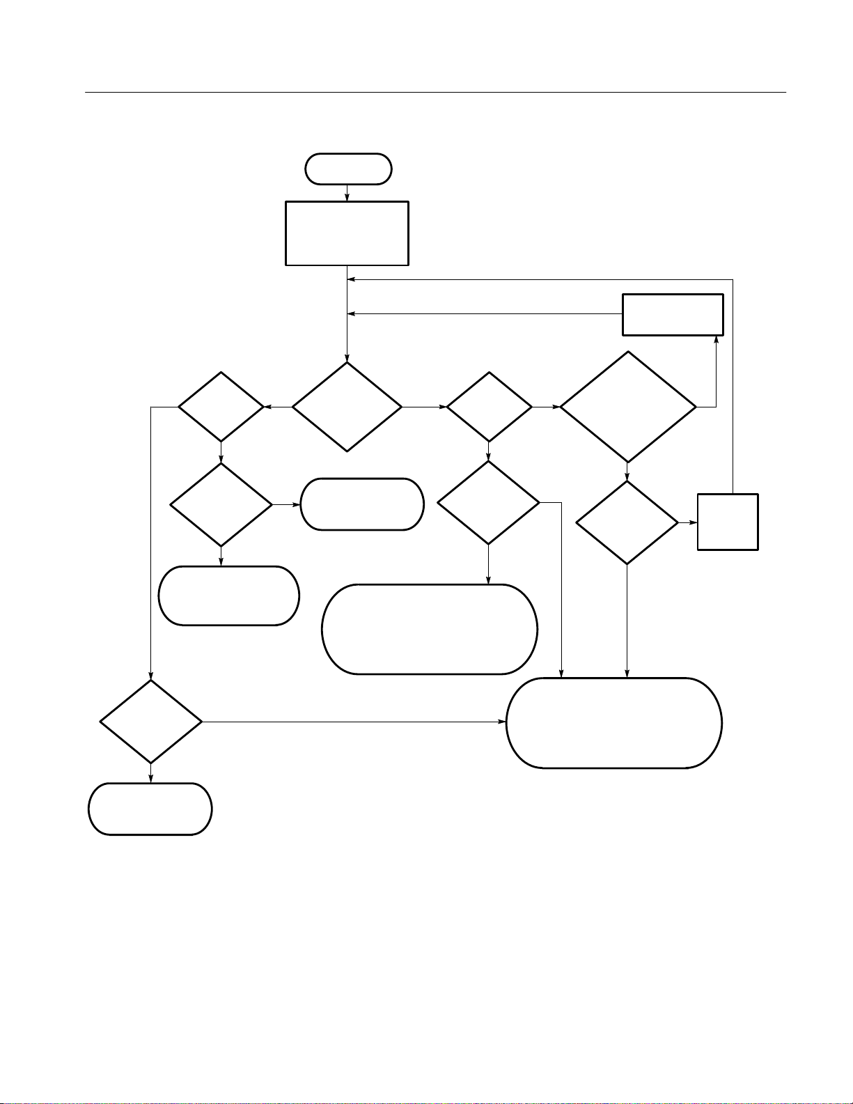
Begin
Remove all modules from
the Mainframe. Turn on
the Mainframe power
switch.
Troubleshooting
Plug in cord at
both ends
Yes
Supply
voltages OK?
(Fig. 6–14)
Yes
Blower
operates?
Supply
voltages OK?
(Fig. 6–14)
Check for failure at Blower
(Fan) Control board,
blower cable, or blower
No
Yes
No
No
Yes
Front panel
LED on?
Check for failure at
power supply
LED cable from LED to J22 on
Series resistor (R60) on monitor
No
Check for failure at
Front-panel LED,
backplane board, or
board (49.9 Ω)
Blower
operates?
Yes
+5VM
voltage OK?
(Fig. 6–14)
Yes
No
No
Power-supply interface board,
Backplane board (blown fuse or
Power cord
connected to
mainframe and
power source?
Yes
Rear-Panel
Fuse closed?
Yes
Check for failure at
Power supply,
bad board)
No
No
Replace
rear-panel
fuse.
Power off Mainframe.
Mainframe OK.
Figure 6–13: Primary troubleshooting procedure
TLA711 Benchtop Chassis Service Manual
6–27
Page 64
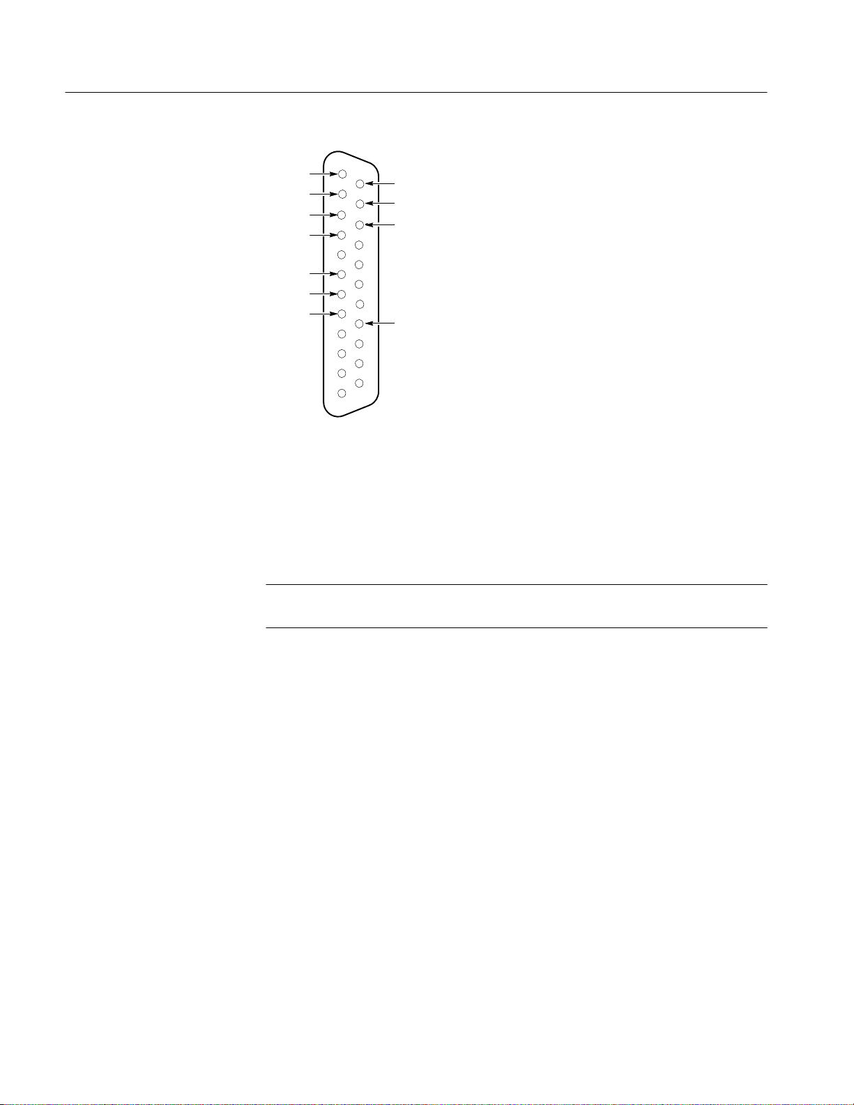
Troubleshooting
+5VM
–12VM
–24VM
–2VM
+5VC
+12VC
+5VB
+12VM
+24VM
–5.2VM
+5VB
Figure 6–14: Rear-panel connector diagram
To begin the procedure, perform the following steps:
1. Use the Primary Troubleshooting Procedure chart on page 6–27 to determine
how to proceed.
Diagnostic Tests Table
NOTE. Before replacing circuit boards, be sure to inspect all associated cables
and connectors for damage and proper installation.
2. If needed, use the Removal and Installation Procedures that begin on
page 6–5 to replace the faulty replaceable part.
The Benchtop Chassis does not include diagnostic tests.
6–28
TLA711 Benchtop Chassis Service Manual
Page 65

Overview of Procedures
Table 6–3 provides a brief overview of the troubleshooting and verification
procedures.
T able 6–3: Troubleshooting overview
Recommended
Procedure
interval
Troubleshooting
Purpose Documented
Incoming test When you initially receive the
unit and open the packing box
Performance verification After board replacement Verifies advertised performance
Troubleshooting When unit fails to work correctly Troubleshoot the Benchtop
Verifies unit is not dead on
arrival
specifications
TLA 700 Series Performance
Verification and Adjustment
T echnical Reference Manual
TLA 700 Series Performance
Verification and Adjustment
T echnical Reference Manual
Chassis, page 6–25
Adjustment After Repair
The benchtop chassis requires no adjustments.
TLA711 Benchtop Chassis Service Manual
6–29
Page 66

Repackaging Instructions
This section contains the information needed to repackage the benchtop chassis
for shipment or storage.
Packaging
If at all possible use the original packaging to ship or store the instrument. If the
original packaging is not available, use a corrugated cardboard shipping carton
having a test strength of at least 275 pounds (125 kg) and with an inside
dimension at least six inches (15.25 cm) greater than the instrument dimensions.
Add cushioning material to prevent the instrument from moving around in the
shipping container.
If the instrument is being shipped to a Tektronix Service Center, enclose the
following information:
H The owner’s address
H Name and phone number of a contact person
H Type and serial number of the instrument
H Reason for returning
H A complete description of the service required
Seal the shipping carton with an industrial stapler or strapping tape.
Mark the address of the Tektronix Service Center and also your own return
address on the shipping carton in two prominent locations.
TLA711 Benchtop Chassis Service Manual
6–31
Page 67

Repackaging Instructions
Storage
The benchtop chassis should be stored in a clean, dry environment. The
following environmental characteristics apply for both shipping and storage:
H Temperature range: –40° F to +160° F (–40° C to +71° C)
H Altitude: To 40,000 feet (12,190 meters)
See Table 1–5 on page 1–7 for a complete listing of the environmental characteristics.
6–32
TLA711 Benchtop Chassis Service Manual
Page 68

Options
T able 7–1: Options
This chapter lists the advertised options for the TLA 711 Benchtop Chassis.
Refer to the Replaceable Mechanical Parts chapter for a list of standard and
optional accessories for the chassis.
NOTE. Service options are listed on the Tektronix Service Options page that
precedes the Table of Contents in this manual.
Tektronix will ship the options shown in Table 7–1:
Option # Label Description
A1 Universal European
power cord
A2 UK power cord 240 V, 50 Hz, 13A power cord
A3 Australian power cord 240 V, 50 Hz, 10A power cord
A4 North American power
cord
A5 Switzerland power cord 220 V , 50 Hz, 10A power cord
1S Sub MF Kit 32 MB DRAM/2.16 GB Hard Disk Upgrade
1A Add LAN PC Card 10BaseT and 10Base2
220 V , 50 Hz, 16A power cord
Delete standard power cord
Delete standard power cord
Delete standard power cord
240 V , 60 Hz, 15A power cord
Delete standard power cord
Delete standard power cord
Delete: Controller w/16 MB DRAM/840 MB HD
Add: Controller w/32 MB DRAM/2.16 GB HD
Note: All current TLA 700 Series SW installed on HD
(Windows 95 SW, QA Plus SW, and TLA 700 Applications SW;
Windows 95 manuals also included)
Add: LAN Package
TLA711 Benchtop Chassis Service Manual
7–1
Page 69

Options
T able 7–1: Options (Cont.)
DescriptionLabelOption #
1M Add 17 inch Monitor Add: 17” color monitor (includes 5’ monitor cable)
Same 15A power cord ordered with TLA 711
2M Add 21 inch Monitor Add: 21” color monitor (includes 5’ monitor cable)
Same 15A power cord ordered w/TLA 711
1K Add LACART Add LACART
95 Add Cal Report Add: Cal (Test Data) Report
7–2
TLA711 Benchtop Chassis Service Manual
Page 70

Electrical Parts List
Refer to the Mechanical Parts List chapter for a complete listing and description
of replaceable parts for the TLA711 Benchtop Chassis.
TLA711 Benchtop Chassis Service Manual
8–1
Page 71

Diagrams
This chapter contains the block diagram and the interconnection diagram for the
benchtop chassis.
Benchtop Controller
Slots 0 – 1
PCI to Backplane
Bridge ASIC
Benchtop Chassis
PC Cards, SVGA, COM,
EPP & Trigger Ports
VTC Trig
ASIC
Module Slot #2
Module Slot #3
PC Controller
Display and I/O
Adapter Board
Floppy
disk drive
Mouse &
Keyboard
Hard
disk drive
Module Slot #12
Backplane
Power Supply
Universal Monitor Blower
Figure 9–1: Interconnections
TLA711 Benchtop Chassis Service Manual
9–1
Page 72

Diagrams
J6
S2/3 J10 P9 S1 J7 J8
Monitor Board
25
A3
Passive Monitor
Fan Speed Switch
3
4
Blower
AC in
3
A1
Power Supply
Interface
Board
P1
J1
Power Supply
0J3 0P1 0P2
30 96
3
P20
P2
P21
J2
96
3
3
0J4 0P3 0J1 0J2
0P1 1P1 2P1 3P1 4P1 5P1 6P1 7P1 8P1 9P1 10P1 11P1 12P1
0P2
J20 J21
J23
J22
1P2 2P2 3P2 4P2 5P2 6P2 7P2 8P2 9P2 10P2
J16
Slot 0 Slot 1 Slot 2 Slot 3 Slot 4 Slot 5 Slot 6 Slot 7 Slot 8 Slot 9
3
J24
A4
Backplane
A2
Temperature Sense Board
Slot 10
11P2
Slot 11
12P2
Slot 12
On / Standby
Switch
Figure 9–2: Chassis block diagram
9–2
TLA711 Benchtop Chassis Service Manual
Page 73

Mechanical Parts List
This chapter contains a list of standard accessories, optional accessories, and
replaceable parts for the Benchtop Chassis. Use this information to identify and
order accessories and replacement parts.
Standard Accessories
The Benchtop Chassis comes standard with the accessories listed in Table 10–1.
T able 10–1: Standard accessories
Accessory Part Number
102-key Win95 Keyboard (US), PS2 mini DIN 119-5193-00
Tek Mouse, 3-button, PS2 mini-DIN 119-4330-02
Dual-wide Slot Panel Fillers (5) 333-4206-00
Single-wide Slot Panel Filler 333-4205-00
SMB-to-BNC cable (2) P6041
Female-to-Female BNC 103-0028-00
Printer Adapter Cable, 3 feet 012-1512-00
Windows 95 Package (SW & Manual) Not orderable
from Tektronix
QA Plus SW 063-2506-00
TLA 700 Application SW 063-1967-00
Jumper with pull-tab (used for flashing module FW) (5) 131-4356-00
TLA 700 User Manual 070-9775-00
TLA 700 Installation Manual 070-9774-00
Certificate of Traceable Calibration
Power Cord, North American, Straight (15 A) 161-0213-00
Power Cord, North American, Straight (20 A) 161-0218-00
Fuse, 6.3A 159-0381-00
Fuse, 20A 159-0379-00
Power Cord, North American, Straight
(for optional monitor)
TLA 711 Shipping List
161-0066-00
TLA711 Benchtop Chassis Service Manual
10–1
Page 74
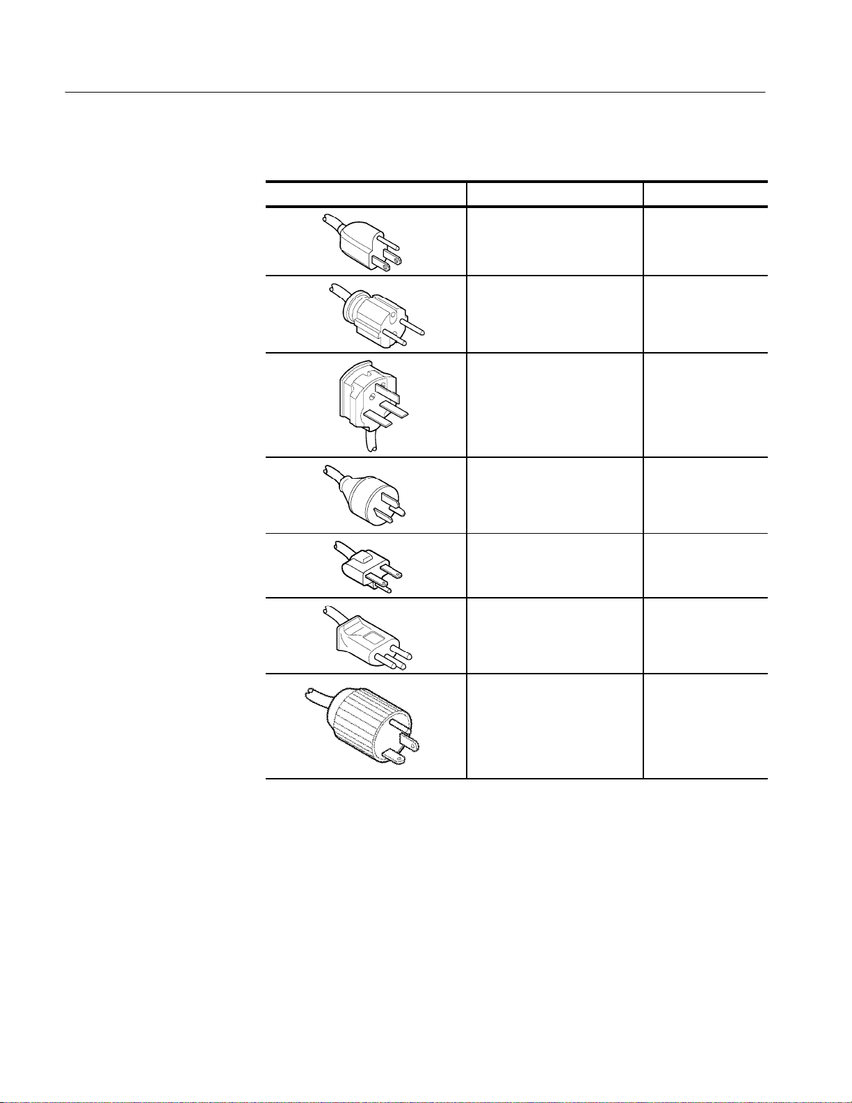
Mechanical Parts List
T able 10–2: Power cord identification
Plug configuration Normal usage Option number
North America
125 V/15A Plug
NEMA 5-15P
Europe
230 V
United Kingdom
230 V
Australia
230 V
North America
230 V
Switzerland
230 V
Standard
A1
A2
A3
A4
A5
10–2
North American
125V/20A Plug
NEMA 5-20P
1A
TLA711 Benchtop Chassis Service Manual
Page 75

Optional Accessories
Mechanical Parts List
You can also order the optional accessories listed in Table 10–3.
T able 10–3: Optional accessories
Accessory Part Number
RS-232 Serial Interface Cable 012-1241-00
TLA 711 Benchtop Mainframe Rackmount Kit 020-2197-00
Option A1 Power cords for the external supply 161-0209-00
161-0066-09
Option A2 Power cords for the external supply 161-0210-00
161-0066-10
Option A3 Power cords for the external supply 161-021 1-00
161-0066-11
Option A4 Power cords for the external supply 161-0208-00
161-0066-12
Option A5 Power cords for the external supply 161-0212-00
Parts Ordering Information
Replacement parts are available through your local Tektronix field office or
representative.
Changes to Tektronix products are sometimes made to accommodate improved
components as they become available and to give you the benefit of the latest
improvements. Therefore, when ordering parts, it is important to include the
following information in your order.
H Part number (see Part Number Revision Level below)
H Instrument type or model number
H Instrument serial number
H Instrument modification number, if applicable
If you order a part that has been replaced with a different or improved part, your
local Tektronix field office or representative will contact you concerning any
change in part number.
161-0154-00
Change information, if any, is located at the rear of this manual.
TLA711 Benchtop Chassis Service Manual
10–3
Page 76

Mechanical Parts List
Part Number Revision
Level
Module Servicing
Tektronix part numbers contain two digits representing the revision level of the
part. For most parts in this manual, you will find the letters XX in place of the
revision level number.
Part Number Revision Level
670-7918-03
When you order parts, Tektronix will provide you with the most current part for
your product type, serial number, and modification (if applicable). At the time of
your order, Tektronix will determine the part number revision level needed for
your product, based on the information you provide.
Modules can be serviced by selecting one of the following options. Contact your
local Tektronix service center or representative for repair assistance.
Module Repair and Return. You may ship your module to us for repair, after which
we will return it to you.
Revision Level May Show as XX
670-7918-XX
New Modules. You may purchase replacement modules in the same way as other
replacement parts.
10–4
TLA711 Benchtop Chassis Service Manual
Page 77

Common Replaceable Parts
Table 10–4 provides a quick reference list of parts that you are most likely to
replace. For more detailed information refer to the individual parts lists in this
chapter.
T able 10–4: Common replaceable parts
Name Description
Fuse Fuse, cartridge:20A,250V,5 Sec Min @
Mechanical Parts List
Tektronix Part
Number
159-0379-00
200%,0.25 X 1.25,US REC:326020
Fuse Fuse, cartridge:5MM X 20MM,250V,6.3A,High Breaking
capacity ,ceramic;VDE
Bottom Card
Guide with
Shutters
Card Guide Guide:Plastic Guide,ECB,VXI Molded Ckt Bd Guide, VXI
Blower (fan) FAN, DC:BLOWER,48V,DUAL INLET, 450 CFM,177
Baffle,VXI Slot:0.040 AL,Formed Sheet Metal with
Perforations
Form Factor,VXI410
W,60 DBA,W/PROGRAMMABLE TACHOMETER
OUT,7.0” L,
159-0381-00
378-2074-XX
351-0962-XX
119–5199–00
TLA711 Benchtop Chassis Service Manual
10–5
Page 78

Mechanical Parts List
Using the Replaceable Parts List
The rest of this chapter contain lists of the replaceable mechanical and/or
electrical components of the Benchtop Chassis. Use these lists to identify and
order replacement parts. The following table describes each column in the lists.
T able 10–5: Parts lists column descriptions
Column
Number
1 Figure & Index
Column Name Description
Figure and index numbers in the exploded view
Number
illustrations.
Abbreviations
Mfr. Code to Manufacturer
Cross Index
2 Tektronix Part
Number
3 and 4 Serial Number Column 3 indicates the serial number at which the part
5 Qty Quantity of parts used.
6 Name & Description An item name is separated from the description by a
7 Mfr. Code Manufacturer code.
8 Mfr. Part Number Manufacturer’s or vendor’s part number.
Use this part number when ordering replacement parts
from Tektronix.
was first effective. Column 4 indicates the serial number at
which the part was discontinued. No entries in either
column indicates the part is good for all serial numbers.
colon (:). Because of space limitations, an item name may
sometimes appear incomplete. Use the U. S. Federal
Catalog Handbook H6-1 for further item name
identification.
Abbreviations conform to American National Standard ANSI Y1.1–1972.
The table titled Manufacturers Cross Index shows codes, names, and addresses
of manufacturers or vendors of components listed in the parts list.
10–6
TLA711 Benchtop Chassis Service Manual
Page 79

Mechanical Parts List
Manufacturers cross index
Mfr.
Code
06383 PANDUIT CORP 17303 RIDGELAND AVE TINLEY PARK, IL 60477–3048
0B445 ELECTRI–CORD MFG CO INC 312 EAST MAIN STREET WESTFIELD, PA 16950
0J9P4 DELTA ENGINEERING & MFG. CO. 19500 SW TETON TUALATIN, OR 97062
0KB01 STAUFFER SUPPLY CO 810 SE SHERMAN PORTLAND, OR 97214–4657
0KB05 NORTH STAR NAMEPLATE INC 5750 NE MOORE COURT HILLSBORO, OR 97124–6474
0L0L7 RADISYS CORPORATION 5445 NE DAWSON CREEK DRIVE HILLSBORO, OR 97124
0VF15 TOTAL TECHNOLOGIES L TD 2110 S ANNE ST SANTA ANNA, CA 92704
0ZQ35 3COM CORPORATION . 5353 BETSY ROSS DRIVE SANTA CLARA, CA 95052–8145
1GM54 ZYTEC CORP 7575 MARKET PLACE DR EDEN PRAIRIE, MN 55344
24931 BERG ELECTRONICS INC BERG ELECTRONICS RF/COAXIAL DIV
26742 METHODE ELECTRONICS INC BACKPLAIN DIVISION
2W733 BELDEN WIRE & CABLE COMPANY 2200 US HWY 27 SOUTH
2W944 PAPST MECHATRONIC CORP AQUIDNECK INDUSTRIAL PARK NEWPORT, RI 02840
51506 ACCURATE SCREW MACHINE CO 19 BALTIMORE ST NUTLEY, NJ 07110–1303
52152 3M COMPANY INDUSTRIAL TAPE DIVISION
5F520 PANEL COMPONENTS CORP PO BOX 115 OSKALOOSA, IA 52577–0115
60128 MICROSOFT CORPORATION ONE MICROSOFT WAY
61081 ELECTRONIC SOLUTIONS 6790 FLANDERS DR SAN DIEGO, CA 92121
63426 NKK SWITCH NIHON KAIHEIKA IND CO LTD
71400 BUSSMANN DIVISION COOPER INDUSTRIES INC
75915 LITTELFUSE INC 800 E NORTHWEST HWY DES PLAINES, IL 60016–3049
7X318 KASO PLASTICS INC 11013 A NE 39TH VANCOUVER, WA 98662
80009 TEKTRONIX INC 14150 SW KARL BRAUN DR
80126 PACIFIC ELECTRICORD CO 747 WEST REDONDO BEACH
8X345 NORTHWEST SPRING MFG CO 5858 WILLOW LANE LAKE OSWEGO, OR 97035
S3109 FELLER U.S. CORPORA TION 72 VERONICA AVE
TK2208 NORTHWEST RUBBER EXTRUDERS INC 16748 SW 72ND AVE PORTLAND, OR 97224
TK2469 UNITREK CORPORATION 3000 LEWIS & CLARK HWY
TK2541 AMERICOR ELECTRONICS LTD UNIT–H
Manufacturer Address City, State, Zip Code
2100 EARLYWOOD DR
PO BOX 547
7444 WEST WILSON AVE
PO BOX 1980
3M CENTER
DEPARTMENT 101
7850 E GELDING DRIVE
PO BOX 14460
PO BOX 500
PO BOX 10
UNIT #4
SUITE 2
2682 W COYLE AVE
FRANKLIN, IN 46131
CHICAGO, IL 60656–4548
RICHMOND, IN 47374
ST PAUL, MN 55144–1000
REDMOND, WA 98052–8300
SCOTTSDALE, AZ 85260
ST LOUIS, MO 63178
BEAVERT ON, OR 97077–0001
GARDENA, CA 90247–4203
SOMERSET, NJ 08873
VANCOUVER, W A 98661
ELK GROVE VILLAGE, IL 60007
TLA711 Benchtop Chassis Service Manual
10–7
Page 80

Mechanical Parts List
Replaceable parts list
Fig. &
Index
Number
10-1–1 212–0193–00 12 SCREW,EXT RLV :8–32 X 0.375 BUTT ON HEAD,HEX
–2 200–4313–00 1 COVER:MAINFRAME COVER,0.050 ALUM,16.72 X 13.18 X
-3 441–2107–00 1 CHASSIS:MAINFRAME CHASSIS ASSY,SHEET
-4 426–2537–00 2 RAIL,FOOT:FOOT RAIL CHASSIS,ALUM SHEET METAL,TV
-5 348–0001–00 4 FOOT,CABINET:BLACK RUBBER TK2208 ORDER BY
–6 212–0193–00 4 SCREW,EXT RLV:8–32 X 0.375 BUTTON HEAD,HEX
-7 212–0158–00 8 SCREW,MACHINE:8–32 X 0.375,PNH,STL,CDPL,T–20 TORXDR0KB01 ORDER BY
Tektronix Part
Number
Serial No.
Effective
Serial No.
Discont’d
Qty Name & Description
CABINET AND CHASSIS ASSEMBL Y
DRIVE,STAINLESS STEEL,BLACK OXIDE FINISH,0.093 DRIV
18.48,PAINTED SILVER GRAY,APOLLO
METAL,PAINTED SILVER GRAY,APOLLO
GRAY,APOLLO
DRIVE,STAINLESS STEEL,BLACK OXIDE FINISH,0.093 DRIV
Mfr.
Code
0KB01 212–0193–00
80009 200–4313–00
80009 441–2107–00
80009 426–2537–00
0KB01 212–0193–00
Mfr. Part Number
DESCRIPTION
DESCRIPTION
10–8
TLA711 Benchtop Chassis Service Manual
Page 81
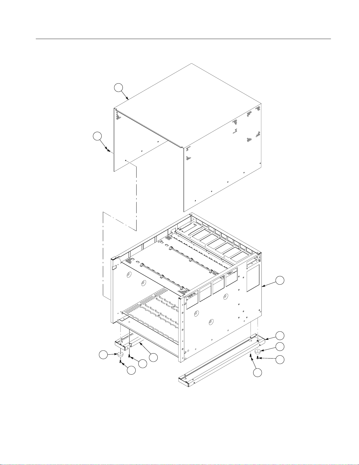
Mechanical Parts List
2
1
5
7
6
Figure 10–1: Cabinet and chassis assembly
TLA711 Benchtop Chassis Service Manual
3
4
5
4
7
6
10–9
Page 82

Mechanical Parts List
Replaceable parts list
Fig. &
Index
Number
10-2-1 260–2618–00 1 SWITCH,PUSH:SPST,MOM,GOLD OVER NICKEL
–2 343–0549–00 2 STRAP,TIEDOWN,E:0.098 W X 4.0 L,ZYTEL 06383 PLT1M
–3 334–9267–00 1 MARKER,IDENT:FRONT TOP PRODUCT ID LABEL, 1.0 X
–4 251–1905–00 1 EXTRUSION:UPPER,CUT EXTRUSION,15.6 LONG, P AINTED
–5 343–0775–00 2 CABLE,CLAMP:RIBBON,1.0 X
–6 174–3424–00 1 CA ASSY,SP:RIBBON,IDC,34,28
–7 671–3219–00 1 CIRCUIT BD ASSY :TEMP SENSE,389–1876–XX
–8 21 1–0720–00 17 SCR,ASSEM WSHR:6–32 X 0.500,PNH,STL,CDPL,T–15 TORX
–9 1 18–9449–00 1 CIRCUIT BD ASSY:BACKPLANE BOARD,13–SLOT,C–SIZE
–10 020-2194--00 1 COMPONENT KIT:BACKPLANE,EMI SHIELD KIT CONTAINS
–11 213–0882–00 12 SCREW,TPG,TR:6–233 X 0.437,PNH,STL,CDPL,TYPE
–12 220–0199–01 2 NUT BAR:VME/VXI NUTBAR,M2.5 THREADS,CUT TO
–13 251–1906–00 1 EXTRUSION:LOWER,CUT EXTRUSION 15.6 LONG, P AINTED
–14 334–9266–00 1 MARKER,IDENT:FRONT BOTTOM SLOT LABEL,0.010
–15 378–2074–01 13 BAFFLE ASSEMBLY :VXI SLOT,0.040 AL,FORMED SHEET
–16 351–0962–00 13 GUIDE:PLASTIC GUIDE,ECB,VXI MOLDED CKT BD
–17 333–4206–00 5 PANEL,FRONT:FRONT PANEL,BLANK,DOUBLE
–18 333–4205–00 1 PANEL,FRONT:FRONT PANEL,BLANK
–19 334–9326–00 1 MARKER,IDENT:LABEL,MICROSOFT WINDOWS 95,TLA704 60128 334–9326–00
Tektronix Part
Number
214–4754–00 1 SPRING:SPRING,0.025 SST,SUBPART OF 378–2074–01
337–3884–00 1 SHIELD,BAFFLE:SHUTTER,0.040 AL ALLOY ,SUBPART OF
351–0962–00 1 GUIDE:PLASTIC GUIDE,ECB,VXI MOLDED CKT BD
Serial No.
Effective
Serial No.
Discont’d
Qty Name & Description
CIRCUIT BOARDS AND CHASSIS PARTS
CONTACTS,0.4V AT 28V,ILLUM BUTT ON,PANEL MNT W/C
15.6, 0.010 LEXAN,3 COLOR,BACKGROUND SILVER GR
SILVER GRAY
1.0,GRAY,POLYVINYL,W/URETHANE FOAM TAPE BACKING
AWG,SPLIT&FOLDED,2X10,RCPT,0.1CTR
WIRED,TESTED
DR,MACHINE
WITH ELECTRONIC AUTOMATIC BUS GRANT
SENSING/GROUN
DIN SHIELD & SCREWS,TLA704,TLA711
TT ,T–15,T ORX DR
15.97LONG
SILVER GRAY
LEXAN,1.00 X 15.60, 3 COLOR,BACKGROUND SILVER GRAY
METAL W/PERFORATIONS,PLASTIC,& SPRING,
ASSY:VX1410
378–2074–01 ASSY ,VX1410
GUIDE,VXI FORM FACTOR,VXI410,SAFETY
GUIDE,VXI FORM FACTOR,VXI410,SAFETY
WIDE,EMI,ALUM, SILVER GRA Y
VXI,SINGLE,ALUM,EMI, SILVER GRA Y,APOLLO
Mfr.
Code
63426 YB15KKG01–04F–J
80009 334–9267–00
80009 251–1905–00
52152 80610029243/3484–
TK2469 174–3424–00
80009 671–3219–00
0KB01 ORDER BY
61081 V1213J1J2X–7059
80009 020–2194–00
0KB01 ORDER BY DESC
80009 220–0199–01
80009 251–1906–00
80009 334–9266–00
80009 378–2074–01
80009 214–4754–00
80009 337–3884–00
7X318 351–0962–00
7X318 351–0962–00
80009 333–4206–00
80009 333–4205–00
Mfr. Part Number
B
1000
DESCRIPTION
10–10
TLA711 Benchtop Chassis Service Manual
Page 83

Mechanical Parts List
6
4
3
2
1
18
17
5
7
5
19
11
12
8
9
10
16
15
12
13
14
Figure 10–2: Circuit boards and chassis parts
TLA711 Benchtop Chassis Service Manual
11
10–11
Page 84

Mechanical Parts List
Replaceable parts list
Fig. &
Index
Number
10-3-1 671–3984–00 1 CKT BD ASSY:STANDARD MONITOR, 389– –00 WIRED 80009 671–3984–00
–2 21 1–0501–00 2 SCREW,MACHINE:6–32 X 0.125,PNH,STL CD PL,POZ 0KB01 211–0501–00
–3 337–4053–01 1 SHIELD,EMI:EMI SHIELD,OUTPUT CONNECTORS ON
–4 343–0549–00 1 STRAP,TIEDOWN,E:0.098 W X 4.0 L,ZYTEL 06383 PLT1M
–5 407–4331–00 1 BRACKET:0.062 ALUM SHEET,MOUNTS MONITOR
–6 214–3903–01 2 SCREW,JACK:4–40 X 0.312 EXT THD,4–40 INT THD,0.188
–7 Not field
–8 21 1–0747–00 4 SCREW,MACHINE:6–32 X 0.188,PNH,STL,CDPL,T–15 TORXDR0KB01 ORDER BY
–9 671–3216–01 1 CIRCUIT BD ASSY:POWER SUPPLY
–10 200–4207–00 1 COVER:0.050 AL,COVER,ECB,PWR SPLY I/F,SHEET
–11 212–0158–00 10 SCREW,MACHINE:8–32 X 0.375,PNH,STL,CDPL,T–20 TORXDR0KB01 ORDER BY
–12 Not field
–13 211–0846–00 4 SCREW:SCREW,SHLDR,6–32 X 0.156,HEX SOCKET
–14 119–4783–03 1 POWER SUPPLY:VXI MAINFRAME POWER SUPPL Y, 1GM54 22923000
–15 367–0466–00 1 HANDLE:WIREFORM,0.125 SST,ELECTRO POLISH,1 X 2
–16 334–9268–00 1 MARKER,IDENT:REAR I/O LABEL,0.010 LEXAN,1.500 X
–17 212–0400–00 4 SCREW,8-32x.250,PNH,STL,T-20 212–0400–00
–18 119–5199–00 1 FAN, DC:BLOWER,48V,DUAL INLET,656 CFM,177 W,60
–19 380–1 109–00 1 HOUSING,FAN:FAN HOUSING ASSY ,SHEET METAL,PAINTED
–20 Not field
Tektronix Part
Number
replaceable
replaceable
replaceable
Serial No.
Effective
Serial No.
Discont’d
Mfr.
Qty Name & Description
POWER SUPPL Y AND BLOWER ASSEMBLY
ENHANCED MONITOR BOARD,0.010 SST,VX1410
ECB,VXI410
HEX,STEEL,CADPLA TE
1 CKT BD:STANDARD MONIT OR, 389– –00 WIRED 80009
INTERFACE,TESTED,389–1879–01,VX1410
METAL,MOUNT PWR SPLY I/F ECB TO PWR SPLY,V
1 CIRCUIT BD:POWER SUPPLY
INTERFACE,TESTED,389–1879–01,VX1410
SHOULDER SCREW,0.156 DIA X 0.125 SHANK
INCH,VX1410
9.515,BACKGROUND COLOR TV GRAY,APOLLO,SAFETY
DBA,W/PROGRAMMABLE TACHOMETER OUT,7.0” L,
TV GRAY,APOLLO
1 MARKER,IDENT:REAR POWER RATING LABEL,0.010
LEXAN,1.500 X 7.500,BACKGROUND COLOR TV
GRAY,APOLL
Code
0J9P4 337–4053–01
0J9P4 407–4331–00
0KB01 214–3903–01
80009 671–3216–01
80009 200–4207–00
80009
51506 67515–S–12–VT
8X345 367–0466–00
80009 334–9268–00
2W944 D1G133–AB11–08A
80009 380–1109–00
Mfr. Part Number
DESCRIPTION
DESCRIPTION
10–12
TLA711 Benchtop Chassis Service Manual
Page 85

Mechanical Parts List
2
3 4
1
12
14
16
15
17
11
5
6
8
7
10
11
9
13
18
19
11
19
20
Figure 10–3: Power supply and blower assembly
TLA711 Benchtop Chassis Service Manual
10–13
Page 86

Mechanical Parts List
Replaceable parts list
Fig. &
Index
Number
10-4-0 020–2197–00 1 COMPONENT KIT:RACKMOUNT KIT, SILVER GRAY , TLA711 80009 020–2197–00
–1 950–0991–00 2 HANDLE ALUMINUM BLK 80009 950099100
–2 212–0157–00 14 SCREW,MACHINE:8–32 X 0.5,FLH,100 DEG,STL CDPL,TORX 0KB01 ORDER BY DESC
–3 407–4481–00 2 BRACKET:RACKMOUNT BRACKET,0.125 CRS,1010.1018
–4 212–0671–00 4 SCREW,MACHINE:10–32 X 0.625,FLH,100 DEG,STL,CD PL,
–5 351–0800–00 1 GUIDE,SLIDE:CHASSIS TRACK,, (PAIR) 06666 CTS–124
Tektronix Part
Number
Serial No.
Effective
Serial No.
Discont’d
Qty Name & Description
1R RACKMOUNT ASSEMBL Y
ALLOY,EG COATED,SILVER GRAY,TLA711
TORX
Mfr.
Code
0J9P4 OBD
0KB01 ORDER BY DESC
Mfr. Part Number
070–9839–00 1 TLA 711 BENCHTOP MAINFRAME RACKMOUNT INSTALLA-
TION INSTRUCTIONS
80009 070-9839-00
10–14
TLA711 Benchtop Chassis Service Manual
Page 87

Mechanical Parts List
4
3
2
1
2
5
Figure 10–4: 1R rackmount assembly
3
2
5
2
TLA711 Benchtop Chassis Service Manual
10–15
Page 88

Mechanical Parts List
Replaceable parts list
Fig. &
Index
Number
Tektronix
Part Number
161–0213–00 1 CABLE ASSY ,PWR:3,16 AWG,2.5
161–0218–00 1 CABLE ASSY ,PWR:3,14 AWG,100 L,SJT,BLK,60 DEG
063–1967–00 1 SOFTWARE PKG:APOLLO SYSTEM SOFTWARE,3.5
012–1512–00 1 CABLE,INTCON:SHLD CMPST,IEEE1284,CRC,25,28
063–2506–00 1 SOFTWARE PKG:QA PLUS, 3.5” FLOPPIES 80009 063–2506–00
070–9774–00 1 MANUAL,TECH:INSTALLATION,TLA700 SERIES,DP 80009 070–9774–00
070–9775–00 1 MANUAL,TECH:USERS,TLA700 SERIES,DP 80009 070–9775–00
119–4330–02 1 TEK MOUSE, 3-BUTTON, PS2 MINI–DIN
119–5193–00 1 KEYBOARD,ASSY:WINDOWS 95 SOLUTION
159–0379–00 1 FUSE,CARTRIDGE:20A,250V,5 SEC MIN @
159–0381–00 1 FUSE,CARTRIDGE:5 X 20 MM,6.3A,250V ,FAST
016–1524–00 1
P6041 2 SMB–to–BNC cable 80009 P6041
Serial No.
Effective
Serial No.
Discont’d
Qty Name & Description Mfr. Code Mfr. Part Number
STANDARD ACCESSORIES
0B445 161–0213–00
METER,SJT,GREY ,105 DEG C,MCA–3T X
BME–3S,13A/250V,NORTH AMERICAN,
0B445 161–0218–00
C,5–20P X BME–3S,15A/125V,
80009 063–1967–00
FLOPPY(1.44MEG)
0VF15 012–1512–00
AWG,17 TWPR,1 METER, 25 POS,FEMALE DSUB
DB25F X 36
80009 119–5193–00
KEYBOARD WITH 4–PIN MINI DIN CONNECTOR
75915 326 020
200%,0.25 X 1.25,UL REC,326020,
71400 GDA–6.3
BLOW,HIGH BREAKING CAPACITY ,UL REC,SEMKO,
10–16
TLA711 Benchtop Chassis Service Manual
Page 89

Replaceable parts list (Cont.)
Fig. &
Index
Number
Tektronix
Part Number
161–0066–09 1 CA ASSY ,PWR:3,0.75MM SQ,250V/10A,99
161–0066–10 1 CA ASSY,PWR:3,1.0 MM SQ,250V/10A,2.5
161–0066–11 1 CA ASSY ,PWR:3,1.0MM SQ,250V/10A,2.5
161–0066–12 1 CA ASSY ,PWR:3,18 AWG,250V/10A,98
161–0154–00 1 CA ASSY ,PWR:3,1.0MM SQ,250V/10A,2.5
119–5510–00 1 LAN PC CARD:ETHERNET PCMCIA ADAPTER W/CE
119–5430–00 1 DISPLAY,MONITOR:17 INCH,COLOR,30–86KHZ
119–5422–00 1 DISPLAY,MONITOR:21 INCH COLOR MULTI–SYNC
070–9773–XX 1 MANUAL,TECH:SERVICE,TLA711 BENCH T OP
070–9775–XX 1 MANUAL,TECH:USER,TLA 700 SERIES LOGIC
070–9776–XX 1 MANUAL,TECH:TECHNICAL REFERENCE,TLA700
070–9777–XX 1 MANUAL,TECH:SERVICE,TLA704 PORTABLE
070–9778–XX 1 MANUAL,TECH:SERVICE,TLA711,BENCHT OP
070–9779–XX 1 MANUAL,TECH:SERVICE,TLA7LX/TLA7MX SERIES
070–9780–XX 1 MANUAL,TECH:SERVICE,TLA7D1,TLA7E1
Serial No.
Effective
Serial No.
Discont’d
Mechanical Parts List
Qty Name & Description Mfr. Code Mfr. Part Number
OPTIONAL ACCESSORIES
INCH,STR,IEC320,RCPT,EUROPEAN,SAFTEY
CONTROLLED,
METER,STR,IEC320,RCPT X 13A,FUSED UK
PLUG(13A FUSE),UNI
METER,STR,IEC320,RCPT,AUSTRALIA,SAFTEY
CONTROLLED,
INCH,STR,IEC320,RCPT X NEMA 6–15P,US,SAFTEY
CONTROLLED,
METER,STR,IEC320,RCPT,SWISS,SAFTEY
CONTROLLED,
MARK, 3COM ETHERLINK III LAN PC CARD, 10
BASE–T & 1
MULTI SYNC, 0.27MM DOT PITCH,FLAT CRT,PWR
SAVING,ON SCREE
MONITOR, 30–95 KHZ,
CHASSIS,DP
ANALYZER ,DP
SERIES PERFORMANCE VERIFICATION AND
ADJUSTMENT ,DP
MAINFRAME,DP
CONTROLLER,DP
LOGIC ANALYZER MODULE,DP
DIGITIZING OSCILLOSCOPE MODULE,DP
2W733 ORDER BY
DESCRIPTION
TK2541 ORDER BY
DESCRIPTION
80126 ORDER BY
DESCRIPTION
S3109 ORDER BY
DESCRIPTION
5F520 86515030
0ZQ35 3C589
80009 119–5430–00
80009 119–5422–00
80009 070–9773–XX
80009 070–9775–XX
80009 070–9776–00
80009 070–9777–XX
80009 070–9778–00
80009 070–9779–XX
80009 070–9780–XX
TLA711 Benchtop Chassis Service Manual
10–17
 Loading...