

Tektronix TLA704, TLA711 User Manual

User Manual
TLA 700 Series
Logic Analyzer
070-9775-04
This document supports application software
version 2.0 and above.

Copyright © T ektronix, Inc. All rights reserved. Licensed software products are owned by Tektronix or its suppliers and
are protected by United States copyright laws and international treaty provisions.
Use, duplication, or disclosure by the Government is subject to restrictions as set forth in subparagraph (c)(1)(ii) of the
Rights in T echnical Data and Computer Software clause at DFARS 252.227-7013, or subparagraphs (c)(1) and (2) of the
Commercial Computer Software – Restricted Rights clause at F AR 52.227-19, as applicable.
T ektronix products are covered by U.S. and foreign patents, issued and pending. Information in this publication supercedes
that in all previously published material. Specifications and price change privileges reserved.
Printed in the U.S.A.
T ektronix, Inc., P.O. Box 1000, Wilsonville, OR 97070–1000
TEKTRONIX and TEK are registered trademarks of T ektronix, Inc.
MagniVu is a trademark of Tektronix, Inc.
Windows and Windows 95 are trademarks of Microsoft Corporation.

WARRANTY
T ektronix warrants that the products that it manufactures and sells will be free from defects in materials and workmanship
for a period of one (1) year from the date of shipment. If a product proves defective during this warranty period, T ektronix,
at its option, either will repair the defective product without charge for parts and labor, or will provide a replacement in
exchange for the defective product.
In order to obtain service under this warranty, Customer must notify Tektronix of the defect before the expiration of the
warranty period and make suitable arrangements for the performance of service. Customer shall be responsible for
packaging and shipping the defective product to the service center designated by T ektronix, with shipping charges prepaid.
T ektronix shall pay for the return of the product to Customer if the shipment is to a location within the country in which the
T ektronix service center is located. Customer shall be responsible for paying all shipping charges, duties, taxes, and any
other charges for products returned to any other locations.
This warranty shall not apply to any defect, failure or damage caused by improper use or improper or inadequate
maintenance and care. T ektronix shall not be obligated to furnish service under this warranty a) to repair damage resulting
from attempts by personnel other than T ektronix representatives to install, repair or service the product; b) to repair
damage resulting from improper use or connection to incompatible equipment; c) to repair any damage or malfunction
caused by the use of non-T ektronix supplies; or d) to service a product that has been modified or integrated with other
products when the effect of such modification or integration increases the time or difficulty of servicing the product.
THIS WARRANTY IS GIVEN BY TEKTRONIX IN LIEU OF ANY OTHER WARRANTIES, EXPRESS OR
IMPLIED. TEKTRONIX AND ITS VENDORS DISCLAIM ANY IMPLIED WARRANTIES OF
MERCHANTABILITY OR FITNESS FOR A PAR TICULAR PURPOSE. TEKTRONIX’ RESPONSIBILITY TO
REP AIR OR REPLACE DEFECTIVE PRODUCTS IS THE SOLE AND EXCLUSIVE REMEDY PROVIDED TO
THE CUSTOMER FOR BREACH OF THIS WARRANTY. TEKTRONIX AND ITS VENDORS WILL NOT BE
LIABLE FOR ANY INDIRECT , SPECIAL, INCIDENTAL, OR CONSEQUENTIAL DAMAGES IRRESPECTIVE
OF WHETHER TEKTRONIX OR THE VENDOR HAS ADVANCE NOTICE OF THE POSSIBILITY OF SUCH
DAMAGES.


WARRANTY
T ektronix warrants that the media on which this software product is furnished and the encoding of the programs on the
media will be free from defects in materials and workmanship for a period of three (3) months from the date of shipment.
If a medium or encoding proves defective during the warranty period, T ektronix will provide a replacement in exchange
for the defective medium. Except as to the media on which this software product is furnished, this software product is
provided “as is” without warranty of any kind, either express or implied. T ektronix does not warrant that the functions
contained in this software product will meet Customer’s requirements or that the operation of the programs will be
uninterrupted or error-free.
In order to obtain service under this warranty, Customer must notify Tektronix of the defect before the expiration of the
warranty period. If T ektronix is unable to provide a replacement that is free from defects in materials and workmanship
within a reasonable time thereafter, Customer may terminate the license for this software product and return this software
product and any associated materials for credit or refund.
THIS WARRANTY IS GIVEN BY TEKTRONIX IN LIEU OF ANY OTHER WARRANTIES, EXPRESS OR
IMPLIED. TEKTRONIX AND ITS VENDORS DISCLAIM ANY IMPLIED WARRANTIES OF
MERCHANTABILITY OR FITNESS FOR A PAR TICULAR PURPOSE. TEKTRONIX’ RESPONSIBILITY TO
REPLACE DEFECTIVE MEDIA OR REFUND CUSTOMER’S PAYMENT IS THE SOLE AND EXCLUSIVE
REMEDY PROVIDED TO THE CUSTOMER FOR BREACH OF THIS WARRANTY. TEKTRONIX AND ITS
VENDORS WILL NOT BE LIABLE FOR ANY INDIRECT , SPECIAL, INCIDENTAL, OR CONSEQUENTIAL
DAMAGES IRRESPECTIVE OF WHETHER TEKTRONIX OR THE VENDOR HAS ADVANCE NOTICE OF
THE POSSIBILITY OF SUCH DAMAGES.


Table of Contents
Getting Started
Operating Basics
General Safety Summary xi. . . . . . . . . . . . . . . . . . . . . . . . . . . . . . . . . . . .
Preface xiii. . . . . . . . . . . . . . . . . . . . . . . . . . . . . . . . . . . . . . . . . . . . . . . . . . .
Related Documentation xiii. . . . . . . . . . . . . . . . . . . . . . . . . . . . . . . . . . . . . . . . . . . .
Contacting T ektronix xv. . . . . . . . . . . . . . . . . . . . . . . . . . . . . . . . . . . . . . . . . . . . . .
Getting Started 1–1. . . . . . . . . . . . . . . . . . . . . . . . . . . . . . . . . . . . . . . . . . . .
Product Description 1–1. . . . . . . . . . . . . . . . . . . . . . . . . . . . . . . . . . . . . . . . . . . . . . .
Installation 1–2. . . . . . . . . . . . . . . . . . . . . . . . . . . . . . . . . . . . . . . . . . . . . . . . . . . . . .
Powering On the Logic Analyzer 1–2. . . . . . . . . . . . . . . . . . . . . . . . . . . . . . . . . . . . .
Powering Off the Logic Analyzer 1–3. . . . . . . . . . . . . . . . . . . . . . . . . . . . . . . . . . . .
Connecting Probes to the T arget System 1–3. . . . . . . . . . . . . . . . . . . . . . . . . . . . . . .
Approaching the Windows 1–6. . . . . . . . . . . . . . . . . . . . . . . . . . . . . . . . . . . . . . . . . .
Programmatic Control 1–17. . . . . . . . . . . . . . . . . . . . . . . . . . . . . . . . . . . . . . . . . . . . .
Backing Up User Files 1–17. . . . . . . . . . . . . . . . . . . . . . . . . . . . . . . . . . . . . . . . . . . . .
Portable Mainframe Front Panel Controls 1–18. . . . . . . . . . . . . . . . . . . . . . . . . . . . . .
For Further Information 1–20. . . . . . . . . . . . . . . . . . . . . . . . . . . . . . . . . . . . . . . . . . . .
Sampling and Digitizing a Signal 2–1. . . . . . . . . . . . . . . . . . . . . . . . . . . . . . . . . . . .
LA Module Block Diagram 2–2. . . . . . . . . . . . . . . . . . . . . . . . . . . . . . . . . . . . . . . . .
DSO Module Block Diagram 2–4. . . . . . . . . . . . . . . . . . . . . . . . . . . . . . . . . . . . . . . .
Logic Analyzer Physical Model 2–5. . . . . . . . . . . . . . . . . . . . . . . . . . . . . . . . . . . . . .
Logic Analyzer Conceptual Model 2–6. . . . . . . . . . . . . . . . . . . . . . . . . . . . . . . . . . .
Intermodule Interactions and Time Correlation 2–7. . . . . . . . . . . . . . . . . . . . . . . . . .
Listing-Data Concepts 2–8. . . . . . . . . . . . . . . . . . . . . . . . . . . . . . . . . . . . . . . . . . . . .
Microprocessor Support 2–9. . . . . . . . . . . . . . . . . . . . . . . . . . . . . . . . . . . . . . . . . . . .
High-Level Language (HLL) Support 2–10. . . . . . . . . . . . . . . . . . . . . . . . . . . . . . . . .
Waveform Data Concepts 2–11. . . . . . . . . . . . . . . . . . . . . . . . . . . . . . . . . . . . . . . . . . .
Performance Analysis Concepts 2–17. . . . . . . . . . . . . . . . . . . . . . . . . . . . . . . . . . . . .
Comparing Acquired Data Against Saved Data 2–18. . . . . . . . . . . . . . . . . . . . . . . . . .
Repetitive Acquisitions 2–19. . . . . . . . . . . . . . . . . . . . . . . . . . . . . . . . . . . . . . . . . . . .
TLA 700 Programmatic Interface (TPI) 2–20. . . . . . . . . . . . . . . . . . . . . . . . . . . . . . .
Symbol Support 2–21. . . . . . . . . . . . . . . . . . . . . . . . . . . . . . . . . . . . . . . . . . . . . . . . . .
Reference
Setup 3–1. . . . . . . . . . . . . . . . . . . . . . . . . . . . . . . . . . . . . . . . . . . . . . . . . . . . .
Starting From the System Window 3–1. . . . . . . . . . . . . . . . . . . . . . . . . . . . . . . . . . .
Setting Up the LA Module 3–3. . . . . . . . . . . . . . . . . . . . . . . . . . . . . . . . . . . . . . . . . .
Setting Up the Trigger Program 3–12. . . . . . . . . . . . . . . . . . . . . . . . . . . . . . . . . . . . . .
Setting Up the DSO Module 3–24. . . . . . . . . . . . . . . . . . . . . . . . . . . . . . . . . . . . . . . .
System Trigger 3–30. . . . . . . . . . . . . . . . . . . . . . . . . . . . . . . . . . . . . . . . . . . . . . . . . . .
Arming Modules 3–31. . . . . . . . . . . . . . . . . . . . . . . . . . . . . . . . . . . . . . . . . . . . . . . . .
Intermodule and External Signaling 3–32. . . . . . . . . . . . . . . . . . . . . . . . . . . . . . . . . .
Merging Modules 3–34. . . . . . . . . . . . . . . . . . . . . . . . . . . . . . . . . . . . . . . . . . . . . . . . .
TLA 700 Series Logic Analyzer User Manual
i

Table of Contents
Saving and Loading Setups, Triggers, and Data 3–35. . . . . . . . . . . . . . . . . . . . . . . . .
System Options 3–39. . . . . . . . . . . . . . . . . . . . . . . . . . . . . . . . . . . . . . . . . . . . . . . . . .
Menu Shortcut Keys 3–40. . . . . . . . . . . . . . . . . . . . . . . . . . . . . . . . . . . . . . . . . . . . . . .
Acquisition 3–41. . . . . . . . . . . . . . . . . . . . . . . . . . . . . . . . . . . . . . . . . . . . . . . .
Starting and Stopping Acquisition 3–41. . . . . . . . . . . . . . . . . . . . . . . . . . . . . . . . . . . .
Viewing Acquisition Activity 3–43. . . . . . . . . . . . . . . . . . . . . . . . . . . . . . . . . . . . . . .
If the Logic Analyzer Does Not Trigger 3–44. . . . . . . . . . . . . . . . . . . . . . . . . . . . . . .
Display 3–47. . . . . . . . . . . . . . . . . . . . . . . . . . . . . . . . . . . . . . . . . . . . . . . . . . .
Opening an Existing Data Window 3–48. . . . . . . . . . . . . . . . . . . . . . . . . . . . . . . . . . .
Opening a Saved Data Window 3–49. . . . . . . . . . . . . . . . . . . . . . . . . . . . . . . . . . . . . .
Aligning Saved Data with Current Data 3–49. . . . . . . . . . . . . . . . . . . . . . . . . . . . . . .
Creating a New Data Window 3–50. . . . . . . . . . . . . . . . . . . . . . . . . . . . . . . . . . . . . . .
General Purpose Data Window Shortcut Keys 3–51. . . . . . . . . . . . . . . . . . . . . . . . . .
Waveform Window 3–53. . . . . . . . . . . . . . . . . . . . . . . . . . . . . . . . . . . . . . . . .
Types of Waveforms 3–54. . . . . . . . . . . . . . . . . . . . . . . . . . . . . . . . . . . . . . . . . . . . . . .
Reading the Waveform Indicators 3–56. . . . . . . . . . . . . . . . . . . . . . . . . . . . . . . . . . . .
Cursor Measurements 3–58. . . . . . . . . . . . . . . . . . . . . . . . . . . . . . . . . . . . . . . . . . . . . .
Jumping to Specific Data Locations 3–59. . . . . . . . . . . . . . . . . . . . . . . . . . . . . . . . . .
Searching Data 3–60. . . . . . . . . . . . . . . . . . . . . . . . . . . . . . . . . . . . . . . . . . . . . . . . . . .
Locking Windows 3–61. . . . . . . . . . . . . . . . . . . . . . . . . . . . . . . . . . . . . . . . . . . . . . . .
MagniV u Data 3–62. . . . . . . . . . . . . . . . . . . . . . . . . . . . . . . . . . . . . . . . . . . . . . . . . . .
Comparing Waveform Data 3–63. . . . . . . . . . . . . . . . . . . . . . . . . . . . . . . . . . . . . . . . .
Adjusting the Waveform Data View 3–65. . . . . . . . . . . . . . . . . . . . . . . . . . . . . . . . . .
Customizing the Waveform Window Data 3–68. . . . . . . . . . . . . . . . . . . . . . . . . . . . .
Exporting Waveform Data 3–68. . . . . . . . . . . . . . . . . . . . . . . . . . . . . . . . . . . . . . . . . .
Printing Waveform Data 3–69. . . . . . . . . . . . . . . . . . . . . . . . . . . . . . . . . . . . . . . . . . .
Waveform Window Shortcut Keys 3–70. . . . . . . . . . . . . . . . . . . . . . . . . . . . . . . . . . . .
Listing Window 3–71. . . . . . . . . . . . . . . . . . . . . . . . . . . . . . . . . . . . . . . . . . . .
Reading the Listing Window Indicators 3–71. . . . . . . . . . . . . . . . . . . . . . . . . . . . . . . .
Jumping to Specific Data Locations 3–73. . . . . . . . . . . . . . . . . . . . . . . . . . . . . . . . . .
Measuring Listing Data 3–75. . . . . . . . . . . . . . . . . . . . . . . . . . . . . . . . . . . . . . . . . . . .
Comparing Listing Data 3–75. . . . . . . . . . . . . . . . . . . . . . . . . . . . . . . . . . . . . . . . . . . .
Searching Data 3–77. . . . . . . . . . . . . . . . . . . . . . . . . . . . . . . . . . . . . . . . . . . . . . . . . . .
Locking Windows 3–78. . . . . . . . . . . . . . . . . . . . . . . . . . . . . . . . . . . . . . . . . . . . . . . .
MagniV u Data 3–79. . . . . . . . . . . . . . . . . . . . . . . . . . . . . . . . . . . . . . . . . . . . . . . . . . .
Adjusting the Listing Data View 3–79. . . . . . . . . . . . . . . . . . . . . . . . . . . . . . . . . . . . .
Customizing the Listing Window Data Area 3–81. . . . . . . . . . . . . . . . . . . . . . . . . . . .
Exporting Listing Data 3–82. . . . . . . . . . . . . . . . . . . . . . . . . . . . . . . . . . . . . . . . . . . . .
Printing Listing Data 3–85. . . . . . . . . . . . . . . . . . . . . . . . . . . . . . . . . . . . . . . . . . . . . .
Listing Window Shortcut Keys 3–86. . . . . . . . . . . . . . . . . . . . . . . . . . . . . . . . . . . . . .
Source Window 3–87. . . . . . . . . . . . . . . . . . . . . . . . . . . . . . . . . . . . . . . . . . . .
Creating a Source Window 3–88. . . . . . . . . . . . . . . . . . . . . . . . . . . . . . . . . . . . . . . . .
Reading the Source Window Indicators 3–89. . . . . . . . . . . . . . . . . . . . . . . . . . . . . . . .
Jumping to Specific Data Locations 3–90. . . . . . . . . . . . . . . . . . . . . . . . . . . . . . . . . .
Moving Through Source Files 3–92. . . . . . . . . . . . . . . . . . . . . . . . . . . . . . . . . . . . . . .
Searching for Source Data 3–95. . . . . . . . . . . . . . . . . . . . . . . . . . . . . . . . . . . . . . . . . .
Adjusting the Source Data View 3–96. . . . . . . . . . . . . . . . . . . . . . . . . . . . . . . . . . . . .
Customizing the Source Window Data Area 3–97. . . . . . . . . . . . . . . . . . . . . . . . . . . .
Locating Source Files 3–97. . . . . . . . . . . . . . . . . . . . . . . . . . . . . . . . . . . . . . . . . . . . . .
Printing Source Data 3–99. . . . . . . . . . . . . . . . . . . . . . . . . . . . . . . . . . . . . . . . . . . . . .
Source Window Shortcut Keys 3–100. . . . . . . . . . . . . . . . . . . . . . . . . . . . . . . . . . . . . .
ii
TLA 700 Series Logic Analyzer User Manual

Appendices
Table of Contents
Histogram Window 3–101. . . . . . . . . . . . . . . . . . . . . . . . . . . . . . . . . . . . . . . . .
Measuring Histogram Data 3–102. . . . . . . . . . . . . . . . . . . . . . . . . . . . . . . . . . . . . . . . .
Creating a Histogram Window 3–103. . . . . . . . . . . . . . . . . . . . . . . . . . . . . . . . . . . . . . .
Adjusting the Histogram Data View 3–104. . . . . . . . . . . . . . . . . . . . . . . . . . . . . . . . . .
Customizing the Histogram Window Data Area 3–105. . . . . . . . . . . . . . . . . . . . . . . . .
Exporting Histogram Data 3–106. . . . . . . . . . . . . . . . . . . . . . . . . . . . . . . . . . . . . . . . . .
Printing Histogram Data 3–107. . . . . . . . . . . . . . . . . . . . . . . . . . . . . . . . . . . . . . . . . . .
Histogram Window Shortcut Keys 3–108. . . . . . . . . . . . . . . . . . . . . . . . . . . . . . . . . . .
Appendix A: Specifications A–1. . . . . . . . . . . . . . . . . . . . . . . . . . . . . . . . . . .
Characteristic Tables A–1. . . . . . . . . . . . . . . . . . . . . . . . . . . . . . . . . . . . . . . . . . . . . .
TLA 704 Color Portable Mainframe Characteristics A–8. . . . . . . . . . . . . . . . . . . . . .
TLA 711 Color Benchtop Chassis Characteristics A–12. . . . . . . . . . . . . . . . . . . . . . . .
TLA 711 Color Benchtop Controller Characteristics A–15. . . . . . . . . . . . . . . . . . . . .
TLA 700 Series Logic Analyzer Module Characteristics A–17. . . . . . . . . . . . . . . . . .
TLA 700 Series Digitizing Oscilloscope Module Characteristics A–24. . . . . . . . . . . .
Appendix B: TLA 700 Symbol File Format B–1. . . . . . . . . . . . . . . . . . . . .
TSF Headers B–2. . . . . . . . . . . . . . . . . . . . . . . . . . . . . . . . . . . . . . . . . . . . . . . . . . . . .
TSF Pattern Symbols B–3. . . . . . . . . . . . . . . . . . . . . . . . . . . . . . . . . . . . . . . . . . . . . .
TSF Range Symbols B–4. . . . . . . . . . . . . . . . . . . . . . . . . . . . . . . . . . . . . . . . . . . . . . .
Appendix C: User Service C–1. . . . . . . . . . . . . . . . . . . . . . . . . . . . . . . . . . . .
General Care C–1. . . . . . . . . . . . . . . . . . . . . . . . . . . . . . . . . . . . . . . . . . . . . . . . . . . . .
Module Self Calibration C–1. . . . . . . . . . . . . . . . . . . . . . . . . . . . . . . . . . . . . . . . . . . .
Preventive Maintenance C–2. . . . . . . . . . . . . . . . . . . . . . . . . . . . . . . . . . . . . . . . . . . .
In Case of Problems C–4. . . . . . . . . . . . . . . . . . . . . . . . . . . . . . . . . . . . . . . . . . . . . . .
Repacking for Shipment C–4. . . . . . . . . . . . . . . . . . . . . . . . . . . . . . . . . . . . . . . . . . . .
Appendix D: Probe and Connector Information D–1. . . . . . . . . . . . . . . . .
P6417 Probe Information D–1. . . . . . . . . . . . . . . . . . . . . . . . . . . . . . . . . . . . . . . . . . .
P6434 Probe Information D–2. . . . . . . . . . . . . . . . . . . . . . . . . . . . . . . . . . . . . . . . . . .
Benchtop Mainframe Remote On/Standby Switch D–3. . . . . . . . . . . . . . . . . . . . . . .
Glossary Index
TLA 700 Series Logic Analyzer User Manual
iii

Table of Contents
List of Figures
Figure 1–1: Portable and benchtop mainframes 1–1. . . . . . . . . . . . . . . . .
Figure 1–2: On/Standby switch locations 1–2. . . . . . . . . . . . . . . . . . . . . . .
Figure 1–3: P6417 17-channel probe 1–4. . . . . . . . . . . . . . . . . . . . . . . . . . .
Figure 1–4: P6434 high-density probe connections 1–5. . . . . . . . . . . . . . .
Figure 1–5: Window usage control flow 1–6. . . . . . . . . . . . . . . . . . . . . . . .
Figure 1–6: System window 1–7. . . . . . . . . . . . . . . . . . . . . . . . . . . . . . . . . .
Figure 1–7: DSO Setup window 1–8. . . . . . . . . . . . . . . . . . . . . . . . . . . . . . .
Figure 1–8: LA Setup window 1–8. . . . . . . . . . . . . . . . . . . . . . . . . . . . . . . .
Figure 1–9: LA Trigger window 1–9. . . . . . . . . . . . . . . . . . . . . . . . . . . . . . .
Figure 1–10: Trigger library 1–10. . . . . . . . . . . . . . . . . . . . . . . . . . . . . . . . . .
Figure 1–11: DSO Trigger window 1–10. . . . . . . . . . . . . . . . . . . . . . . . . . . .
Figure 1–12: Listing window 1–11. . . . . . . . . . . . . . . . . . . . . . . . . . . . . . . . .
Figure 1–13: Waveform window 1–12. . . . . . . . . . . . . . . . . . . . . . . . . . . . . .
Figure 1–14: Histogram window 1–13. . . . . . . . . . . . . . . . . . . . . . . . . . . . . .
Figure 1–15: Source window 1–14. . . . . . . . . . . . . . . . . . . . . . . . . . . . . . . . .
Figure 1–16: Comparing regular and MagniVu data 1–15. . . . . . . . . . . . .
Figure 1–17: Save and Load operations in the File menu 1–16. . . . . . . . . .
Figure 1–18: Using a property sheet to customize the display 1–17. . . . . .
Figure 1–19: Portable mainframe front panel 1–18. . . . . . . . . . . . . . . . . . .
Figure 1–20: GlidePoint pad 1–18. . . . . . . . . . . . . . . . . . . . . . . . . . . . . . . . .
Figure 1–21: Locations of external connectors 1–19. . . . . . . . . . . . . . . . . . .
Figure 2–1: Acquiring a digital signal (LA module) 2–1. . . . . . . . . . . . . .
Figure 2–2: Acquiring an analog signal (DSO module) 2–2. . . . . . . . . . . .
Figure 2–3: Block diagram of the LA module acquisition and
storage 2–2. . . . . . . . . . . . . . . . . . . . . . . . . . . . . . . . . . . . . . . . . . . . . . . .
Figure 2–4: Block diagram of the DSO module acquisition and
storage 2–5. . . . . . . . . . . . . . . . . . . . . . . . . . . . . . . . . . . . . . . . . . . . . . . .
Figure 2–5: Logic analyzer physical model 2–6. . . . . . . . . . . . . . . . . . . . . .
Figure 2–6: Logic analyzer conceptual model 2–7. . . . . . . . . . . . . . . . . . .
Figure 2–7: Listing data 2–8. . . . . . . . . . . . . . . . . . . . . . . . . . . . . . . . . . . . .
Figure 2–8: Listing window with analog data 2–9. . . . . . . . . . . . . . . . . . . .
Figure 2–9: Listing data using a microprocessor support package 2–9. .
Figure 2–10: High-level source code 2–10. . . . . . . . . . . . . . . . . . . . . . . . . . .
Figure 2–11: Source code viewed as acquired data 2–11. . . . . . . . . . . . . . .
Figure 2–12: Waveform data 2–11. . . . . . . . . . . . . . . . . . . . . . . . . . . . . . . . .
Figure 2–13: Using the DSO module to capture a runt pulse 2–13. . . . . . .
iv
TLA 700 Series Logic Analyzer User Manual

Table of Contents
Figure 2–14: LA module sampling resolution 2–14. . . . . . . . . . . . . . . . . . . .
Figure 2–15: Aliasing 2–15. . . . . . . . . . . . . . . . . . . . . . . . . . . . . . . . . . . . . . . .
Figure 2–16: LA module triggering on a glitch 2–16. . . . . . . . . . . . . . . . . .
Figure 2–17: DSO module triggering on a glitch 2–17. . . . . . . . . . . . . . . . .
Figure 2–18: Viewing the performance of code with a Histogram
window 2–18. . . . . . . . . . . . . . . . . . . . . . . . . . . . . . . . . . . . . . . . . . . . . . . .
Figure 2–19: Using color to show memory differences in a Listing
window 2–19. . . . . . . . . . . . . . . . . . . . . . . . . . . . . . . . . . . . . . . . . . . . . . . .
Figure 2–20: Defining repetitive setups 2–20. . . . . . . . . . . . . . . . . . . . . . . . .
Figure 2–21: Using symbols in a trigger program 2–21. . . . . . . . . . . . . . . .
Figure 2–22: Waveforms using pattern symbols 2–23. . . . . . . . . . . . . . . . .
Figure 2–23: Listing data using range symbols 2–23. . . . . . . . . . . . . . . . . .
Figure 2–24: Symbols dialog box 2–24. . . . . . . . . . . . . . . . . . . . . . . . . . . . . .
Figure 2–25: Load Symbol Options dialog box 2–25. . . . . . . . . . . . . . . . . .
Figure 3–1: System window 3–1. . . . . . . . . . . . . . . . . . . . . . . . . . . . . . . . . .
Figure 3–2: Opening a Waveform window from the System window 3–2
Figure 3–3: The LA module Setup window 3–3. . . . . . . . . . . . . . . . . . . . .
Figure 3–4: Setup window with the QSTART support package 3–4. . . . .
Figure 3–5: Selecting channels for memory compare 3–5. . . . . . . . . . . . .
Figure 3–6: Enabling data compare 3–6. . . . . . . . . . . . . . . . . . . . . . . . . . .
Figure 3–7: Channel grouping table in the Setup window 3–10. . . . . . . . .
Figure 3–8: The Activity Indicators dialog box 3–11. . . . . . . . . . . . . . . . . .
Figure 3–9: Probe Thresholds dialog box 3–12. . . . . . . . . . . . . . . . . . . . . . .
Figure 3–10: LA module Trigger window 3–13. . . . . . . . . . . . . . . . . . . . . . .
Figure 3–11: Trigger window structure 3–14. . . . . . . . . . . . . . . . . . . . . . . . .
Figure 3–12: Overview portion of LA Trigger window 3–15. . . . . . . . . . . .
Figure 3–13: Trigger detail portion of LA Trigger window 3–15. . . . . . . .
Figure 3–14: Using trigger storage 3–23. . . . . . . . . . . . . . . . . . . . . . . . . . . .
Figure 3–15: DSO Setup window 3–25. . . . . . . . . . . . . . . . . . . . . . . . . . . . . .
Figure 3–16: DSO Setup window vertical input settings 3–27. . . . . . . . . . .
Figure 3–17: DSO Setup window Horizontal settings 3–28. . . . . . . . . . . . .
Figure 3–18: Signals property page 3–32. . . . . . . . . . . . . . . . . . . . . . . . . . . .
Figure 3–19: Merging modules 3–34. . . . . . . . . . . . . . . . . . . . . . . . . . . . . . . .
Figure 3–20: Logic analyzer conceptual model 3–35. . . . . . . . . . . . . . . . . .
Figure 3–21: Saving a system with data 3–36. . . . . . . . . . . . . . . . . . . . . . . .
Figure 3–22: Load System Options dialog box 3–37. . . . . . . . . . . . . . . . . . .
Figure 3–23: Saving a file in a personalized trigger library 3–38. . . . . . . .
Figure 3–24: Defining setups for Repetitive mode 3–43. . . . . . . . . . . . . . . .
TLA 700 Series Logic Analyzer User Manual
v

Table of Contents
Figure 3–25: The Status Monitor 3–43. . . . . . . . . . . . . . . . . . . . . . . . . . . . . .
Figure 3–26: The Listing and Waveform windows 3–47. . . . . . . . . . . . . . .
Figure 3–27: Opening a data window 3–48. . . . . . . . . . . . . . . . . . . . . . . . . .
Figure 3–28: New Data Window wizard 3–50. . . . . . . . . . . . . . . . . . . . . . . .
Figure 3–29: Waveform window 3–53. . . . . . . . . . . . . . . . . . . . . . . . . . . . . .
Figure 3–30: Waveform types 3–54. . . . . . . . . . . . . . . . . . . . . . . . . . . . . . . . .
Figure 3–31: Magnitude waveform 3–55. . . . . . . . . . . . . . . . . . . . . . . . . . . .
Figure 3–32: Range readouts 3–55. . . . . . . . . . . . . . . . . . . . . . . . . . . . . . . . .
Figure 3–33: Waveform window cursors and marks 3–56. . . . . . . . . . . . . .
Figure 3–34: Using the Go To dialog box to jump to the
system trigger 3–59. . . . . . . . . . . . . . . . . . . . . . . . . . . . . . . . . . . . . . . . . .
Figure 3–35: Using the Overview Mark bar to jump to a
data location 3–59. . . . . . . . . . . . . . . . . . . . . . . . . . . . . . . . . . . . . . . . . . .
Figure 3–36: Defining search criteria 3–61. . . . . . . . . . . . . . . . . . . . . . . . . .
Figure 3–37: Lock Windows dialog box 3–61. . . . . . . . . . . . . . . . . . . . . . . .
Figure 3–38: MagniVu data 3–62. . . . . . . . . . . . . . . . . . . . . . . . . . . . . . . . . .
Figure 3–39: Adding a MagniVu data source to a data window 3–63. . . . .
Figure 3–40: Selecting compare data colors in the Waveform
Window property page 3–64. . . . . . . . . . . . . . . . . . . . . . . . . . . . . . . . . . .
Figure 3–41: Viewing LA compare data in a Waveform window 3–65. . . .
Figure 3–42: Add Waveform dialog box 3–66. . . . . . . . . . . . . . . . . . . . . . . .
Figure 3–43: Waveform with a glitch 3–67. . . . . . . . . . . . . . . . . . . . . . . . . .
Figure 3–44: Property page 3–68. . . . . . . . . . . . . . . . . . . . . . . . . . . . . . . . . .
Figure 3–45: Listing window 3–71. . . . . . . . . . . . . . . . . . . . . . . . . . . . . . . . .
Figure 3–46: Listing window cursors and marks 3–72. . . . . . . . . . . . . . . . .
Figure 3–47: Using the Go To dialog box to jump to the
system trigger 3–74. . . . . . . . . . . . . . . . . . . . . . . . . . . . . . . . . . . . . . . . . .
Figure 3–48: Using the Overview Mark bar to jump to a
data location 3–74. . . . . . . . . . . . . . . . . . . . . . . . . . . . . . . . . . . . . . . . . . .
Figure 3–49: Selecting compare data colors in the Listing
Window property page 3–76. . . . . . . . . . . . . . . . . . . . . . . . . . . . . . . . . . .
Figure 3–50: Viewing LA compare data in a Listing window 3–77. . . . . . .
Figure 3–51: Defining search criteria 3–78. . . . . . . . . . . . . . . . . . . . . . . . . .
Figure 3–52: Lock Windows dialog box 3–79. . . . . . . . . . . . . . . . . . . . . . . .
Figure 3–53: Add Column dialog box 3–80. . . . . . . . . . . . . . . . . . . . . . . . . .
Figure 3–54: Export Data dialog box 3–82. . . . . . . . . . . . . . . . . . . . . . . . . .
Figure 3–55: Export Data Options dialog box 3–83. . . . . . . . . . . . . . . . . . .
Figure 3–56: Source window 3–87. . . . . . . . . . . . . . . . . . . . . . . . . . . . . . . . .
Figure 3–57: Source window cursors and marks 3–89. . . . . . . . . . . . . . . . .
vi
TLA 700 Series Logic Analyzer User Manual

Table of Contents
Figure 3–58: Using the Go To dialog box to jump to the
cursor location 3–91. . . . . . . . . . . . . . . . . . . . . . . . . . . . . . . . . . . . . . . . . .
Figure 3–59: Using the Overview Mark bar to jump to a
data location 3–91. . . . . . . . . . . . . . . . . . . . . . . . . . . . . . . . . . . . . . . . . . .
Figure 3–60: Source window controls 3–92. . . . . . . . . . . . . . . . . . . . . . . . . .
Figure 3–61: Defining source search criteria 3–96. . . . . . . . . . . . . . . . . . . .
Figure 3–62: Source Files property page 3–98. . . . . . . . . . . . . . . . . . . . . . . .
Figure 3–63: Histogram window 3–101. . . . . . . . . . . . . . . . . . . . . . . . . . . . . .
Figure 3–64: Selecting the data source for the Histogram window 3–102. .
Figure 3–65: Measuring events with the Histogram window 3–103. . . . . . .
Figure 3–66: Export Histogram dialog box 3–106. . . . . . . . . . . . . . . . . . . . .
Figure 3–67: ASCII histogram data file 3–107. . . . . . . . . . . . . . . . . . . . . . . .
Figure A–1: Front and side views of TLA 704 Color Portable
Mainframe A–11. . . . . . . . . . . . . . . . . . . . . . . . . . . . . . . . . . . . . . . . . . . . .
Figure A–2: Front view and side view of standard Benchtop chassis A–14
Figure A–3: Front view and side view of Benchtop chassis with
Rackmount Option A–14. . . . . . . . . . . . . . . . . . . . . . . . . . . . . . . . . . . . . .
Figure D–1: P6417 probe footprints D–1. . . . . . . . . . . . . . . . . . . . . . . . . . .
Figure D–2: P6417 probe podlet clearance D–1. . . . . . . . . . . . . . . . . . . . . .
Figure D–3: Connector used for remote On/Standby switch D–3. . . . . . .
TLA 700 Series Logic Analyzer User Manual
vii

Table of Contents
List of Tables
Table 2–1: Using symbols in logic analyzer windows 2–22. . . . . . . . . . . . .
Table 3–1: LA Trigger library 3–16. . . . . . . . . . . . . . . . . . . . . . . . . . . . . . . .
Table 3–2: Trigger events 3–20. . . . . . . . . . . . . . . . . . . . . . . . . . . . . . . . . . . .
Table 3–3: Trigger resources 3–21. . . . . . . . . . . . . . . . . . . . . . . . . . . . . . . . .
Table 3–4: Trigger actions 3–22. . . . . . . . . . . . . . . . . . . . . . . . . . . . . . . . . . .
Table 3–5: Menu shortcut keys 3–40. . . . . . . . . . . . . . . . . . . . . . . . . . . . . . .
Table 3–6: General purpose data window shortcut keys 3–51. . . . . . . . . .
Table 3–7: Waveform window cursor and mark summary 3–57. . . . . . . .
Table 3–8: Waveform window shortcut keys 3–70. . . . . . . . . . . . . . . . . . . .
Table 3–9: Listing window cursor and mark summary 3–72. . . . . . . . . . .
Table 3–10: Listing window shortcut keys 3–86. . . . . . . . . . . . . . . . . . . . . .
Table 3–11: Source window cursor and mark summary 3–89. . . . . . . . . .
Table 3–12: Source window shortcut keys 3–100. . . . . . . . . . . . . . . . . . . . . .
Table 3–13: Histogram window shortcut keys 3–108. . . . . . . . . . . . . . . . . . .
Table A–1: Atmospheric characteristics (mainframes and modules) A–2
Table A–2: Backplane interface (portable and benchtop
mainframes) A–3. . . . . . . . . . . . . . . . . . . . . . . . . . . . . . . . . . . . . . . . . . .
Table A–3: External signal interface (portable and benchtop
mainframes) A–5. . . . . . . . . . . . . . . . . . . . . . . . . . . . . . . . . . . . . . . . . . .
Table A–4: Certifications and compliances: TLA 704 Color Portable
Mainframe1 and TLA 711 Color Benchtop Mainframe1 A–7. . . . . .
Table A–5: Portable mainframe internal controller A–8. . . . . . . . . . . . . .
Table A–6: Portable mainframe display system A–8. . . . . . . . . . . . . . . . .
Table A–7: Portable mainframe front-panel interface A–9. . . . . . . . . . . .
Table A–8: Portable mainframe rear-panel interface A–9. . . . . . . . . . . . .
Table A–9: Portable mainframe AC power source A–10. . . . . . . . . . . . . . .
Table A–10: Portable mainframe secondary power A–10. . . . . . . . . . . . . . .
Table A–11: Portable mainframe cooling A–11. . . . . . . . . . . . . . . . . . . . . . .
Table A–12: Portable mainframe mechanical A–11. . . . . . . . . . . . . . . . . . .
Table A–13: Benchtop chassis AC power source A–12. . . . . . . . . . . . . . . . .
Table A–14: Benchtop chassis secondary power A–12. . . . . . . . . . . . . . . . .
Table A–15: Benchtop chassis cooling A–13. . . . . . . . . . . . . . . . . . . . . . . . .
Table A–16: Benchtop chassis mechanical A–13. . . . . . . . . . . . . . . . . . . . . .
Table A–17: Benchtop controller characteristics A–15. . . . . . . . . . . . . . . .
Table A–18: Benchtop controller mechanical characteristics A–16. . . . . .
Table A–19: LA module channel width and depth A–17. . . . . . . . . . . . . . .
viii
TLA 700 Series Logic Analyzer User Manual

Table of Contents
Table A–20: LA module clocking A–17. . . . . . . . . . . . . . . . . . . . . . . . . . . . .
Table A–21: LA module trigger system A–19. . . . . . . . . . . . . . . . . . . . . . . .
Table A–22: LA module input parameters (with P6417 Probe) A–21. . . . .
Table A–23: LA module MagniVu feature A–21. . . . . . . . . . . . . . . . . . . . . .
Table A–24: Merged LA modules A–22. . . . . . . . . . . . . . . . . . . . . . . . . . . . .
Table A–25: LA module data handling A–22. . . . . . . . . . . . . . . . . . . . . . . .
Table A–26: LA module mechanical A–23. . . . . . . . . . . . . . . . . . . . . . . . . . .
Table A–27: DSO module signal acquisition system A–24. . . . . . . . . . . . . .
Table A–28: DSO module timebase system A–27. . . . . . . . . . . . . . . . . . . . .
Table A–29: DSO module trigger system A–27. . . . . . . . . . . . . . . . . . . . . . .
Table A–30: DSO module front-panel connectors A–29. . . . . . . . . . . . . . . .
Table A–31: DSO module certifications and compliances A–29. . . . . . . . .
Table A–32: DSO module mechanical A–30. . . . . . . . . . . . . . . . . . . . . . . . .
TLA 700 Series Logic Analyzer User Manual
ix

Table of Contents
x
TLA 700 Series Logic Analyzer User Manual

General Safety Summary
Review the following safety precautions to avoid injury and prevent damage to
this product or any products connected to it. To avoid potential hazards, use this
product only as specified.
Only qualified personnel should perform service procedures.
To Avoid Fire or
Personal Injury
Use Proper Power Cord. Use only the power cord specified for this product and
certified for the country of use.
Connect and Disconnect Properly . Do not connect or disconnect probes or test
leads while they are connected to a voltage source.
Ground the Product. This product is grounded through the grounding conductor
of the power cord. To avoid electric shock, the grounding conductor must be
connected to earth ground. Before making connections to the input or output
terminals of the product, ensure that the product is properly grounded.
Observe All Terminal Ratings. To avoid fire or shock hazard, observe all ratings
and marking on the product. Consult the product manual for further ratings
information before making connections to the product.
The common terminal is at ground potential. Do not connect the common
terminal to elevated voltages.
Do not apply a potential to any terminal, including the common terminal, that
exceeds the maximum rating of that terminal.
Use Proper AC Adapter. Use only the AC adapter specified for this product.
Do Not Operate Without Covers. Do not operate this product with covers or panels
removed.
Use Proper Fuse. Use only the fuse type and rating specified for this product.
Avoid Exposed Circuitry. Do not touch exposed connections and components
when power is present.
Do Not Operate With Suspected Failures. If you suspect there is damage to this
product, have it inspected by qualified service personnel.
Do Not Operate in Wet/Damp Conditions.
Do Not Operate in an Explosive Atmosphere.
Keep Product Surfaces Clean and Dry .
Provide Proper Ventilation. Refer to the manual’s installation instructions for
details on installing the product so it has proper ventilation.
TLA 700 Series Logic Analyzer User Manual
xi
General Safety Summary
Symbols and Terms
T erms in this Manual. These terms may appear in this manual:
WARNING. Warning statements identify conditions or practices that could result
in injury or loss of life.
CAUTION. Caution statements identify conditions or practices that could result in
damage to this product or other property.
T erms on the Product. These terms may appear on the product:
DANGER indicates an injury hazard immediately accessible as you read the
marking.
WARNING indicates an injury hazard not immediately accessible as you read the
marking.
CAUTION indicates a hazard to property including the product.
Symbols on the Product. The following symbols may appear on the product:
WARNING
High Voltage
Protective Ground
(Earth) T erminal
CAUTION
Refer to Manual
Double
Insulated
xii
TLA 700 Series Logic Analyzer User Manual

Preface
This manual contains operating information for the TLA 700 Series Logic
Analyzer. The manual consists of the following sections:
H Chapter 1: Getting Started. Provides basic information about using the logic
analyzer.
H Chapter 2: Operating Basics. Describes some logic analyzer concepts.
H Chapter 3: Reference. Describes how to configure and operate the logic
analyzer.
H Appendix A: Specifications. Lists the environmental, physical, and electrical
properties of the logic analyzer and LA module probes.
H Appendix B: TLA 700 Symbol File Format. Provides information on the
contents of symbol files using the TLA 700 Symbol File format.
H Appendix C: User Service. Provides user service information.
H Appendix D: Probe and Connector Information. Provides logic analyzer
probe and connector information.
Related Documentation
In addition to this user manual, the following documentation is available for your
TLA 700 Series Logic Analyzer:
H The TLA 700 Series Logic Analyzer Installation Manual provides installa-
tion information for the TLA 700 Series Logic Analyzer.
H The online help provides information about the TLA 700 Series user
interface and the TLA 700 Programmatic Interface (TPI). To view the online
help, select Help Topics from the Help menu.
H The online release notes provide last-minute product and software informa-
tion not included in this manual. Refer to Release Notes on page 1–21 for
information on viewing the release notes.
H A series of microprocessor support instruction manuals provide operating
and service instructions for the individual microprocessor support packages.
H The TLA 700 Series TLA 7QS QuickStart Training Manual provides training
exercises to help you learn key features of the TLA 700 Series Logic
Analyzer. The training manual is designed to be used with the TLA 7QS
QuickStart training board.
TLA 700 Series Logic Analyzer User Manual
xiii

Preface
H The TLA 700 Series TLA 7QS QuickStart Technical Reference Manual
provides technical and service information for the TLA 7QS QuickStart
training board.
H The TLA 700 Series Performance Verification and Adjustment Technical
Reference Manual provides performance verification and adjustment
procedures for the major components of the TLA 700 Series Logic Analyzer.
The manual includes the performance verification and adjustment software.
H The TLA 711 Color Benchtop Chassis Service Manual provides board-level
service information for the benchtop chassis.
H The TLA 711 Color Benchtop Controller Service Manual provides board-
level service information for the benchtop mainframe controller module.
H The TLA 704 Color Portable Mainframe Service Manual provides board-
level service information for the portable mainframe.
H The TLA 700 Series Logic Analyzer Modules TLA 7Lx and TLA 7Mx Service
Manual provides board-level service information for the LA modules.
H The TLA 700 Series DSO Modules TLA 7Dx and TLA 7Ex Service Manual
provides board-level service information for the DSO modules.
H The P6434 Mass Termination Probe Instructions provides instructions for
using the P6434 probes.
xiv
TLA 700 Series Logic Analyzer User Manual

Contacting Tektronix
Preface
Product
Support
Service
Support
For other
information
To write us Tektronix, Inc.
For application-oriented questions about a Tektronix measurement product, call toll free in North America:
1-800-TEK-WIDE (1-800-835-9433 ext. 2400)
6:00 a.m. – 5:00 p.m. Pacific time
Or, contact us by e-mail:
tm_app_supp@tek.com
For product support outside of North America, contact your
local Tektronix distributor or sales office.
Contact your local Tektronix distributor or sales office. Or, visit
our web site for a listing of worldwide service locations.
http://www.tek.com
In North America:
1-800-TEK-WIDE (1-800-835-9433)
An operator will direct your call.
P.O. Box 1000
Wilsonville, OR 97070-1000
U.S.A.
TLA 700 Series Logic Analyzer User Manual
xv

Preface
xvi
TLA 700 Series Logic Analyzer User Manual

Getting Started

Getting Started
Product Description
This chapter provides basic information about using the logic analyzer. There is
information about the physical instrument and introductory information about
how to operate it. Once you have a basic grasp of this information, proceed to
the next chapter, Operating Basics, for a conceptual model of how the logic
analyzer works.
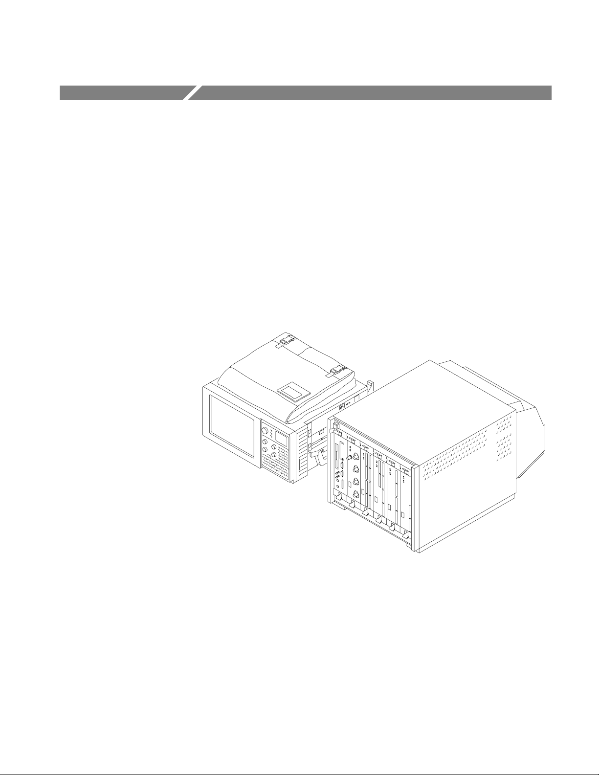
The TLA 700 Series Logic Analyzer is a configurable instrument that combines
a high-performance logic analyzer with a digitizing storage oscilloscope. There
are two mainframe styles, portable and benchtop, as shown in Figure 1–1.
Figure 1–1: Portable and benchtop mainframes
Several logic analyzer (LA) modules are available, in various combinations of
channel width and memory depth. All provide simultaneous state and timing
measurements through a single probe.
The LA module implements a feature called MagniVu, an acquisition technology
that enables each of the LA modules to offer 500 picosecond timing resolution
on all channels. MagniVu data is always available for all channels and requires
no additional probing.
TLA 700 Series Logic Analyzer User Manual
1–1

Getting Started
The digitizing storage oscilloscope (DSO) module incorporates digital real-time
signal acquisition. DSO module data is tightly correlated with data from other
modules, for displays and for intermodule triggering and signalling.
The user interface is built on the familiar Windows 95 operating system. In
addition to using an interface you probably already know, this means that you
can install any PC-compatible, third-party hardware and software on the
instrument.
Installation
Installation information for the TLA 700 Series mainframe, modules, and
software is located in the TLA 700 Series Logic Analyzer Installation Manual.
Powering On the Logic Analyzer
Power on the logic analyzer as follows:
1. Press the On/Standby switch to power on the logic analyzer (see Figure 1–2
for the switch location).
2. Wait for the logic analyzer to complete power-on self-tests, start Windows,
and start the TLA 700 application.
Figure 1–2: On/Standby switch locations
1–2
TLA 700 Series Logic Analyzer User Manual
Powering Off the Logic Analyzer
The portable mainframe has a built-in soft power-off function that safely powers
off the mainframe when you press the On/Standby switch. If you have the
benchtop mainframe, you must power off the mainframe using the Windows 95
shutdown process before depressing the On/Standby switch.
You can set the shutdown mode in the Mainframe Utilities tool in the Windows 95 control panel.
CAUTION. When powering off the benchtop mainframe, use the Windows 95 shut
down procedure. Powering down the benchtop mainframe prematurely can
corrupt the software on the hard disk.
Connecting Probes to the Target System
Getting Started
General Purpose
Connections
The logic analyzer connects to the target system through probes. The LA probes
allow you to connect to the target system in several different ways as shown in
the following illustrations. You can use the color-coded probe channels to map
the hardware connections to the channel settings in the LA Setup window. Each
LA probe group consists of eight channels that can be individually named in the
LA Setup menu.
Connect the probes to the logic analyzer by matching the color-coded label to the
label on the LA module. To provide a secure connection to the LA module, you
can optionally use the probe retainer bracket with the probe connector.
The P6417 probes provide a means to connect to the target system for most
applications. Figure 1–3 shows different ways to connect the probe to the target
system.
Note the location of the ground connections for the probe:
H The individual podlets have the ground (GND) engraved on the podlet.
H When you use the 8-channel leadsets, the ground lead is a single black
connector. Make sure you connect the ground side of the 8-channel lead set
to the ground side of the 8-channel podlet holder.
Refer to Appendix D: Probe and Connector Information for information on
dimensions for the P6417 probes.
TLA 700 Series Logic Analyzer User Manual
1–3

Getting Started
1–4
Figure 1–3: P6417 17-channel probe
TLA 700 Series Logic Analyzer User Manual

Getting Started
High-Density Probe
Connections
The P6434 Mass Termination Probe allows you to connect 34 LA channels to a
microprocessor probe adapter or directly to the target system. To connect to the
target system directly, you must include compatible Mictor connectors in your
circuit board design.
Figure 1–4 shows two ways of connecting the LA module to a target system. For
more information on the P6434 Mass Termination Probe and how to connect it to
your target system, refer to the P6434 Mass Termination Probe Instructions.
Figure 1–4: P6434 high-density probe connections
Microprocessor
Connections
TLA 700 Series Logic Analyzer User Manual
Both the P6417 and the P6434 probes can be connected to microprocessor
adapters. Refer to the documentation that comes with your microprocessor
disassembler package for details about connecting the probes to the microprocessor adapters and to the target system.
1–5
Getting Started
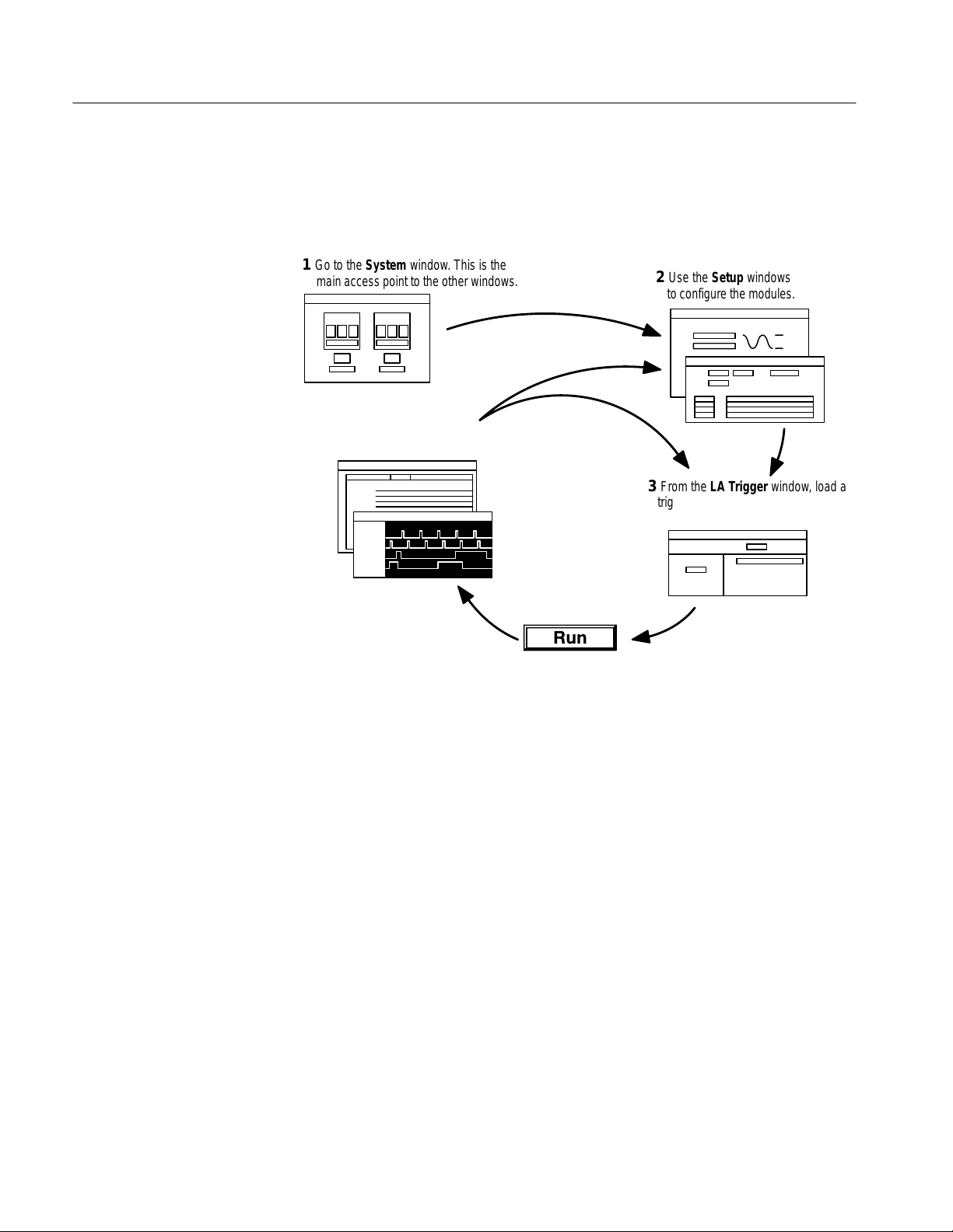
Approaching the Windows
Typically, you use the windows in this application as shown in Figure 1–5.
1 Go to the System window. This is the
main access point to the other windows.
5 View data in the data
windows.
4 Click the Run toolbar
button to acquire data.
Figure 1–5: Window usage control flow
2 Use the Setup windows
to configure the modules.
3 From the LA Trigger window, load a
trigger program from the library and
customize it for your application.
1–6
TLA 700 Series Logic Analyzer User Manual
 Loading...