

Tektronix TLA7012, TLA7016 Reference manual

Technical Reference Manual
TLA7000 Series Mainframes
071-1764-00
This document applies to System Software version 5.0 and above.
Warning
The servicing instructions are for use by qualified
personnel only. To avoid personal injury, do not
perform any servicing unless you are qualified to
do so. Refer to all safety summaries prior to
performing service.
www.tektronix.com

Copyright © Tektronix, Inc. All rights reserved. Licensed software products are owned by Tektronix or its subsidiaries or
suppliers, and are protected by national copyright laws and international treaty provisions.
Tektronix products are covered by U.S. and foreign patents, issued and pending. Information in this publication supercedes
that in all previously published material. Spec ifications and price change privileges reserved.
TEKTRONIX and TEK are registered trademarks of Tektronix, Inc.
Contacting Tektronix
Tektronix, Inc.
14200 SW Karl Braun Drive
P.O. Box 500
Beaverton, OR 97077
USA
For product information, sales, service, and technical support:
H In North America, call 1-800-833-9200.
H Worldwide, visit www.tektronix.com to find contacts in your a rea.

Warranty 2
Tektronix warrants that this product will be free from defects in materials and workmanship for a period of one (1)
year from the date of shipment. If any such product proves defective during this warranty period, Tektronix, at its
option, either will repair the defective product without charge for parts and labor, or will provide a re placement in
exchange for the defective product. Parts, modules and replacement products used by Tektronix for warranty work
may be new or reconditioned to like new performance. All replaced parts, modules and products become the
property of Tektronix.
In order to obtain service under this warranty, Customer must notify Tektronix of the defect before the expiration
of the warranty period and make suitable arrangements for the performance of service. Customer shall be
responsible for packaging and shipping the defective product to the service center designated by Tektronix, with
shipping charges prepaid. Tektronix shall pay for the return of the product to Customer if the shipment is to a
location within the country in which the Tektronix service center is located. Customer shall be responsible for
paying all shipping charges, duties, taxes, and any other charges for products ret urned to any other locations.
This warranty shall not apply to any defect, failure or damage caused by improper use or improper or inadequate
maintenance and care. Tektronix shall not be obligated to furnish service under this warranty a) to repair damage
resulting from attempts by personnel other than Tektronix representatives to install, repair or service the product;
b) to repair damage resulting from improper use or c onnection to incom patible equipment; c) to repair any
damage or malfunction caused by the use of non-Tektronix supplies; or d) to service a product that has been
modified or integrated with other products when the effect of such modification or integration increases the time
or difficulty of servicing the product.
THIS WARRANTY IS GIVEN BY TEKTRONIX WITH RESPECT TO THE PRODUCT IN LIEU OF ANY
OTHER WARRANTIES, EXPRESS OR IMPLIED. TEKTRONIX AND ITS VENDORS DISCLAIM ANY
IMPLIED WARRANTIES OF MERCHANTABILITY OR FITNESS FOR A PARTICULAR PURPOSE.
TEKTRONIX’ RESPONSIBILITY TO REPAIR OR REPLACE DEFECTIVE PRODUCTS IS THE SOLE AND
EXCLUSIVE REMEDY PROVIDED TO THE CUSTOMER FOR BREACH OF THIS WARRANTY.
TEKTRONIX AND ITS VENDORS WILL NOT BE LIABLE FOR ANY INDIRECT, SPECIAL, INCIDENTAL,
OR CONSEQUENTIAL DAMAGES IRRESPECTIVE OF WHETHER TEKTRONIX OR THE VENDOR HAS
ADVANCE NOTICE OF THE POSSIBILITY OF SUCH DAMAGES.


Table of Contents
General Safety Summary v...................................
Service Safety Summary vii....................................
Environmental Considerations viii...............................
Preface ix...................................................
Manual Structure ix................................................
Manual Conventions ix..............................................
Mainframes ix.................................................
Replaceable Parts ix............................................
Related Documentation x...........................................
Introduction xi..............................................
Adjustment and Certification Interval xi................................
Service Strategy xi.................................................
Service Offerings xi................................................
Warranty Repair Service xii.......................................
Calibration and Repair Service xii..................................
Maintenance 1..............................................
Preventing ESD 1.................................................
Inspection and Cleaning 2...........................................
Exterior Inspection 2...........................................
Exterior Cleaning Procedure 3....................................
Interior Inspection 3............................................
Interior Cleaning Procedure 4....................................
Portable Mainframe Removal and Installation Procedures 5.......
Equipment Required 5..............................................
Instrument Covers 6..............................................
Front Panel Display 8.............................................
DVD Drive 10.....................................................
Motherboard 10....................................................
Interface Board 11.................................................
Backplane 12......................................................
Power Supply 13...................................................
Benchtop Mainframe Removal and Installation Procedures 15......
Equipment Required 15..............................................
Instrument Modules 16..............................................
Blower Assembly 16................................................
Removing the Enhanced Monitor Board 19..............................
Power Supply 21...................................................
Mainframe Cover 22................................................
Card Guides 23....................................................
Temperature Sense Board 25..........................................
Front Panel and Display Module 26....................................
EMI DIN Shields 29................................................
Backplane 30......................................................
Repackaging Instructions 33...................................
Packaging 33......................................................
TLA7000 Series Mainframe Technical Reference Manual
i

Table of Contents
Shipping to the Service Center 33......................................
Parts List 35.................................................
Parts Ordering Information 35.........................................
Part Number Revision Level 36....................................
Module Servicing 36............................................
Using the Replaceable Parts List 37....................................
Abbreviations 37...............................................
Mfr. Code to Manufacturer Cross Index 37...........................
ii
TLA7000 Series Mainframe Technical Reference Manual

List of Figures
Table of Contents
Figure 1: Locator diagram 6..................................
Figure 2: Instrument enclosure detail 7.........................
Figure 3: Tilt the panel forward for cable access 8................
Figure 4: Front panel cable locations 9..........................
Figure 5: Dress the cables properly 9...........................
Figure 6: Removing the motherboard 11.........................
Figure 7: Removing the interface board 12.......................
Figure 8: Removing the backplane 13...........................
Figure 9: Location of blower assembly screws 17..................
Figure 10: Removing the blower assembly 18.....................
Figure 11: Removing the blower 18..............................
Figure 12: Removing the enhanced monitor board 19..............
Figure 13: Removing the power supply 21........................
Figure 14: Removing the mainframe cover 22.....................
Figure 15: Removing the top and bottom card guides 24............
Figure 16: Removing the temperature sense board 26..............
Figure 17: Removing the instrument front panel 27................
Figure 18: Installing the new front panel 28......................
Figure 19: Removing the backplane EMI DIN shields 29...........
Figure 20: Removing the backplane 31..........................
Figure 21: Soft power down jumper setting 32....................
Figure 22: External parts 41...................................
Figure 23: Front panel assembly 43.............................
Figure 24: Interface, backplane and motherboard 45..............
Figure 25: Power supply and fans 47............................
Figure 26: Cabinet and chassis assembly 49......................
Figure 27: Circuit boards and chassis parts 51....................
Figure 28: Power supply, monitor, and fan assembly 53............
Figure 29: Slot 0 Interface module 54............................
Figure 30: iView cables 55.....................................
TLA7000 Series Mainframe Technical Reference Manual
iii

Table of Contents
List of Tables
Table i: Tektronix Logic Analyzer Family documentation x........
T able 1: External inspection check list 2........................
T able 2: Internal inspection check list 3........................
Table 3: Equipment required to service the mainframes 5.........
Table 4: Equipment required to service the mainframes 15.........
Table 5: Enhanced monitor board jumpers 20....................
Table 6: Mainframe backplane jumpers 32.......................
Table 7: Parts lists column descriptions 37.......................
iv
TLA7000 Series Mainframe Technical Reference Manual

General Safety Summary
Review the following safety precautions to avoid injury and prevent damage to
this product or any products connected to it.
To avoid potential hazards, use this product only as specified.
Only qualified personnel should perform service procedures.
While using this product, you may need to access other parts of a larger system.
Read the safety sections of the other component manuals for warnings and
cautions related to operating the system.
ToAvoidFireor
Personal Injury
Use Proper Power Cord. Use only the power cord specified for this product and
certified for the country of use.
Connect and Disconnect Properly. Do not connect or disconnect probes or test
leads while they are connected to a voltage source.
Ground the Product. This product is grounded through the grounding conductor
of the power cord. To avoid electric shock, the grounding conductor must be
connected to earth ground. Before making connections to the input or output
terminals of the product, ensure that the product is properly grounded.
Observe All Terminal Ratings. To avoid fire or shock hazard, observe all ratings
and markings on the product. Consult the product manual for further ratings
information before making connections to the product.
The inputs are not rated for connection to mains or Category II, III, or IV
circuits.
Do not apply a potential to any terminal, including the common terminal, that
exceeds the maximum rating of that terminal.
Power Disconnect. The power cord disconnects the product from the power
source. Do not block the power cord; it must remain accessible to the user at all
times.
Do Not Operate Without Covers. Do not operate this product with covers or panels
removed.
Do Not Operate With Suspected Failures. If you suspect there is damage to this
product, have it inspected by qualified service personnel.
Avoid Exposed Circuitry. Do not touch exposed connections and components
when power is present.
Use Proper Fuse. Use only the fuse type and rating specified for this product.
Do Not Operate in Wet/Damp Conditions.
TLA7000 Series Mainframe Technical Reference Manual
v
General Safety Summary
Do Not Operate in an Explosive Atmosphere.
Keep Product Surfaces Clean and Dry.
Provide Proper Ventilation. Refer to the manual’s installation instructions for
details on installing the product so it has proper ventilation.
Terms in this Manual
Symbols and Terms
on the Product
These terms may appear in this manual:
WARNING. Warning statements identify conditions or practices that could result
in injury or loss of life.
CAUTION. Caution statements identify conditions or practices that could result in
damage to this product or other property.
These terms may appear on the product:
H DANGER indicates an injury hazard immediately accessible as you read the
marking.
H WARNING indicates an injury hazard not immediately accessible as you
read the marking.
H CAUTION indicates a hazard to property including the product.
The following symbols may appear on the product:
CAUTION
Refer to Manual
WARNING
High Voltage
vi
Protective Ground
(Earth) Terminal
Chassis Ground
Standby
TLA7000 Series Mainframe Technical Reference Manual

Service Safety Summary
Only qualified personnel should perform service procedures. Read this Service
Safety Summary and the General Safety Summary before performing any service
procedures.
Do Not Service Alone. Do not perform internal service or adjustments of this
product unless another person capable of rendering first aid and resuscitation is
present.
Disconnect Power. To avoid electric shock, switch off the instrument power, then
disconnect the power cord from the mains power.
Use Care When Servicing With Power On. Dangerous voltages or currents may
exist in this product. Disconnect power, remove battery (if applicable), and
disconnect test leads before removing protective panels, soldering, or replacing
components.
To avoid electric shock, do not touch exposed connections.
TLA7000 Series Mainframe Technical Reference Manual
vii
Environmental Considerations
This section provides information about the environmental impact of the
product.
Product End-of-Life
Handling
Observe the following guidelines when recycling an instrument or component:
Equipment Recycling. Production of this equipment required the extraction and
use of natural resources. The equipment may contain substances that could be
harmful to the environment or human health if improperly handled at the
product’s end of life. In order to avoid release of such substances into the
environment and to reduce the use of natural resources, we encourage you to
recycle this product in an appropriate system that will ensure that most of the
materials are reused or recycled appropriately.
The symbol shown to the left indicates that this product
complies with the European Union’s requirements
according to Directive 2002/96/EC on waste electrical and
electronic equipment (WEEE). For information about
recycling options, check the Support/Service section of the
Tektronix Web site (www.tektronix.com).
Mercury Notification. This product uses an LCD backlight lamp that contains
mercury. Disposal may be regulated due to environmental considerations. Please
contact your local authorities or, within the United States, the Electronics
Industries Alliance (www.eiae.org) for disposal or recycling information.
Restriction of Hazardous
Substances
viii
This product has been classified as Monitoring and Control equipment, and is
outside the scope of the 2002/95/EC RoHS Directive. This product is known to
contain lead, cadmium, mercury, and hexavalent chromium.
TLA7000 Series Mainframe Technical Reference Manual

Preface
Manual Structure
Manual Conventions
This is the service manual for the TLA7012 Portable Mainframe and the
TLA7016 Benchtop Mainframe. For service information on the TLA7PC1, refer
to the documentation that came with the product.
This document contains the following information:
H Maintenance contains information and procedures for doing corrective
maintenance on the instruments. Included are instructions for removal and
installation of replaceable parts.
H Mechanical Parts List includes tables of all replaceable parts for the
instrument along with the Tektronix part number.
This manual uses certain conventions that you should become familiar with
before attempting service.
Mainframes
Replaceable Parts
The TLA7012 Portable Mainframe has a built-in controller and display with
room for two TLA plug-in modules. The benchtop mainframe consists of a
mainframe with an interface module. Slots are available for installing other
modules.
This manual refers to any field-replaceable assembly or mechanical part
specifically by its name or generically as a replaceable part. In general, a
replaceable part is any circuit board or assembly, such as the hard disk drive, or a
mechanical part, such as the I/O port connectors, that is listed in the replaceable
parts list.
TLA7000 Series Mainframe Technical Reference Manual
ix

Preface
Related Documentation
The following documents are available as part of the Tektronix Logic Analyzer
Family documentation set. The procedures in this manual assume that the service
personnel have access to the manuals listed in the following table. Contact your
local Tektronix Service Representative for the latest part numbers of the service
documentation. All manuals are available at the Tektronix Web Site.
Table i: Tektronix Logic Analyzer Family documentation
Manual name Description
TLA Quick Start User Manuals High--level operational overview
Online Help In-depth operation and User Interface help
Installation Quick Reference Cards High-- level installation information
Installation Manuals Detailed first-time installation information
TLA Product Specifications & Performance Verification Procedures Product specifications and performance verification procedures for
TLA7000 series products
Field upgrade kits Upgrade information for your logic analyzer
Optional Service Manuals Self-service documentation for modules and mainframes
x
TLA7000 Series Mainframe Technical Reference Manual

Introduction
This manual contains information needed to service the TLA7000 series
mainframes.
To prevent personal injury or damage to the instrument, consider the following
requirements before attempting service:
H Read the General Safety Summary and Service Safety Summary found at the
beginning of this manual.
H The procedures in this manual should only be performed by a qualified
service person.
Be sure to follow all warnings, cautions and notes.
Adjustment and Certification Interval
Generally, you should perform the adjustments and certification (calibration)
once per year, or following repairs that may affect adjustment or calibration.
Service Strategy
Service Offerings
This manual supports and contains information needed for periodic maintenance
of the instrument. It supports and contains the following information for
corrective maintenance:
H Supports removal and replacement of boards or assemblies.
H Supports removal and replacement of the mechanical parts listed in the parts
lists.
This manual does not support component-level fault isolation and replacement.
Tektronix provides service to cover repair under warranty as well as other
services that are designed to meet your specific service needs.
Whether providing warranty repair service or any of the other services listed
below, Tektronix service technicians are equipped to service the instrument.
Services are provided at Tektronix Services Centers and on-site at your facility,
depending on your location.
TLA7000 Series Mainframe Technical Reference Manual
xi

Introduction
Warranty Repair Service
Calibration and Repair
Service
Tektronix warrants this product for one year from date of purchase. The warranty
is located behind the title page in this manual. Tektronix technicians provide
warranty service at most Tektronix service locations worldwide. The Tektronix
product catalog lists all service locations worldwide.
In addition to warranty repair, Tektronix Service offers calibration and other
services which provide solutions to your service needs and quality standards
compliance requirements.
The following services can be tailored to fit your requirements for calibration
and/or repair of your portable mainframe.
Service Options. Tektronix Service Options can be selected at the time you
purchase your instrument. You select these options to provide the services that
best meet your service needs.
Service Agreements. If service options are not added to the instrument purchase,
then service agreements are available on an annual basis to provide calibration
services or post-warranty repair coverage. Service agreements may be customized to meet special turn-around time and/or on-site requirements.
Service on Demand. Tektronix offers calibration and repair services on a
“per-incident” basis that is available with standard prices.
Self Service. Tektronix supports repair to the replaceable-part level by providing
for circuit board exchange.
Use this service to reduce down-time for repair by exchanging circuit boards for
remanufactured ones. Tektronix ships updated and tested exchange boards. Each
board comes with a 90-day service warranty.
For More Information. Contact your local Tektronix service center or sales
engineer for more information on any of the Calibration and Repair Services just
described.
xii
TLA7000 Series Mainframe Technical Reference Manual
Maintenance
Preventing ESD
This chapter provides information and procedures for removing and replacing
components in the TLA7012 Portable Mainframe and the TLA7016 Benchtop
Mainframe.
WARNING. To avoid electric shock, always power off the instrument and
disconnect the power cord before cleaning or servicing the instrument.
When performing any service which requires internal access to the instrument,
adhere to the following precautions to avoid damaging internal circuit boards and
their components due to electrostatic discharge (ESD).
CAUTION. Many components within the instrument are susceptible to static
discharge damage.
Service the instrument only in a static-free environment. Observe standard
handling precautions for static-sensitive devices.
1. Minimize handling of static-sensitive circuit boards.
2. Transport and store static-sensitive circuit boards in their static protected
containers or on a metal rail. Label any package that contains static-sensitive
boards.
3. Discharge the static voltage from your body by wearing a grounded antistatic
wrist strap while handling these circuit boards.
4. Nothing capable of generating or holding a static charge should be allowed
on the work station surface.
5. Handle circuit boards by the edges when possible.
6. Do not slide the circuit boards over any surface.
7. Avoid handling circuit boards in areas that have a floor or work-surface
covering capable of generating a static charge.
TLA7000 Series Mainframe Technical Reference Manual
1
Maintenance
Inspection and Cleaning
The instrument is inspected mechanically and electrically before shipment. It
should be free of marks or scratches and should meet or exceed all electrical
specifications. To confirm this, inspect for physical damage incurred during
transit. Retain the packaging in case shipment for repair is necessary. If there is
damage or deficiency, contact your local Tektronix representative.
Cleaning procedures consist of exterior and interior cleaning. Periodic cleaning
reduces instrument breakdown and increases reliability. Clean the instrument as
needed, based on your operating environment.
Exterior Inspection
Inspect the outside of the instrument for damage, wear, and missing parts. Use
Table 1 as a guide. Modules that appear to have been dropped or otherwise
abused should be checked thoroughly to verify correct operation and performance. Immediately repair defects that could cause personal injury or lead to
further damage to the benchtop controller, expansion module, or the mainframes
that the module plug into.
Table 1: External inspection check list
Item Inspect for Repair action
Front panel Cracks, scratches, deformations,
missing or damaged retainer
screws, or ejector handles.
Front and rear connectors
Accessories Missing items or parts of items,
Broken shells, cracked insulation,
and deformed contacts. Dirt in
connectors.
bent pins, broken or frayed
cables, and damaged connectors.
Replace defective or missing
parts.
Replace defective parts. Clear dirt
out of connectors.
Replace damaged or missing
parts, frayed cables.
CAUTION. To prevent damage to electrical components from moisture during
external cleaning, use only enough liquid to dampen the cloth or applicator.
2
TLA7000 Series Mainframe Technical Reference Manual
Maintenance
Exterior Cleaning
Procedure
Interior Inspection
Clean the exterior surfaces with a soft dry lint-free cloth, or a soft-bristle brush.
If any dirt remains, use a soft cloth or swab dipped in a 75% isopropyl alcohol
solution. Use a swab to clean narrow spaces around controls and connectors. Do
not use abrasive cleaning compounds.
CAUTION. Avoid getting moisture inside the instrument during exterior cleaning;
use just enough moisture to dampen the cloth or swab.
Use only deionized water when cleaning. Use a 75% isopropyl alcohol solution
as a cleanser and rinse with deionized or distilled water.
Do not use chemical cleaning agents; they may damage the chassis. Avoid
chemicals that contain benzene, toluene, xylene, acetone, or similar solvents.
Remove the module covers to access the inside of the instrument for inspection
and cleaning. Refer to the Removal and Installation Procedures for detailed
information on cover removal. Inspect the internal portions of the modules and
the mainframes for damage and wear using Table 2 as a guide. Defects found
should be repaired immediately.
Table 2: Internal inspection check list
Item Inspect for Repair action
Circuit boards Loose, broken, or corroded
solder connections. Burned
circuit boards. Burned, broken,
or cracked circuit-run plating.
Solder connections Cold solder or rosin joints. Return to a Tektronix Service Center.
Wiring and cables Loose plugs or connectors.
Burned, broken, or frayed
wiring.
Chassis Dents, deformations, and
damaged hardware.
Return to a Tektronix Service Center.
Firmly seat connectors. Repair or replace
parts with defective wires or cables.
Straighten, repair, or replace defective
hardware.
CAUTION. To prevent damage from electrical arcing, ensure that circuit boards
and components are dry before applying power.
TLA7000 Series Mainframe Technical Reference Manual
3

Maintenance
Interior Cleaning
Procedure
Use a dry, low-velocity stream of air to clean the interior of the modules and the
mainframes. Use a soft-bristle brush for cleaning around components. If you
must use a liquid for minor interior cleaning, use a 75% isopropyl alcohol
solution and rinse with deionized or distilled water.
Clean the exterior (face) of the DVD drive and replaceable hard disk drive
cartridge with a soft, clean cloth and a mild detergent.
4
TLA7000 Series Mainframe Technical Reference Manual
Portable Mainframe Removal and Installation Procedures
This section provides procedures for removing and installing mechanical and
electrical modules in the portable mainframe. The following procedures provide
only high-level remove and replacement procedures. Refer to the Replaceable
Parts Lists for additional remove and replace information.
CAUTION. Before doing this or any other procedure in this manual, read the
General Safety Summary and Service Safety Summary found at the beginning of
this manual.
Equipment Required
Table 3 lists the tools needed to remove and replace components in the mainframe.
Table 3: Equipment required to service the mainframes
Item number Item Descri pti on
1 Screwdriver handle Accepts Torx driver bits
2 T-15 Torx tip Torx drive bit for T-15 size screws
3 Phillips screwdriver Phillips #1 screwdriver
4 3/16-inch nut driver For motherboard and jack screw removal
5 9/16-inch socket For interface board removal
6 Torque wrench 2 in-lb minimum
NOTE. When installing the screws, use a torque screwdriver and tighten the
screws to 8 in-lbs unless otherwise noted.
TLA7000 Series Mainframe Technical Reference Manual
5
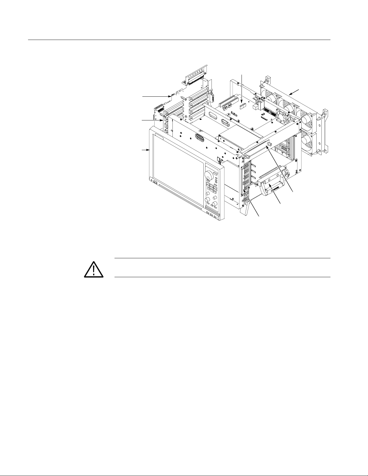
Portable Mainframe Removal and Installation Procedures
Interface
board
Backplane
board
Front panel
and display
Motherboard
Fan
assembly
Hard disk
drive
Power
supply
DVD
drive
Instrument Covers
Figure 1: Locator diagram
WARNING. To avoid electric shock, always power off the instrument and
disconnect the power cord before cleaning or servicing the instrument.
Complete the following steps to remove the instrument covers:
1. Disconnect all cords, cables, and probes from the instrument.
2. Carefully remove all instrument modules (if any) from the instrument.
3. Set the instrument on the bottom feet.
4. Remove the six T-15 screws from the right cover and remove the cover.
6
TLA7000 Series Mainframe Technical Reference Manual
 Loading...