

Page 1

Instruction Manual
TLA6UP
Logic Analyzer Field Upgrade Kit
071-0866-06
This document applies to TLA System Software
version 5.1.
Warning
These servicing instructions are for use by
qualified personnel only. To avoid personal injury,
do not perform any servicing unless you are
qualified to do so. Refer to all safety summaries
prior to performing service.
www.tektronix.com
Page 2

Copyright © Tektronix, Inc. All rights reserved. Licensed software products are owned by Tektronix or its subsidiaries or
suppliers, and are protected by national copyright laws and international treaty provisions.
Tektronix products are covered by U.S. and foreign patents, issued and pending. Information in this publication supercedes
that in all previously published material. Specifications and price c hange privileges reserved.
TEKTRONIX and TEK are registered trademarks of Tektronix, Inc.
Contacting Tektronix
Tektronix, Inc.
14200 SW Karl Braun Drive
P.O. Box 500
Beaverton, OR 97077
USA
For product information, sales, service, and technical support:
H In North America, call 1-800-833-9200.
H Worldwide, visit www.tektronix.com to find contacts in your area.
Page 3

Warranty 6
Tektronix warrants that the parts and modules (“parts”) that it manufactures and sells will be free from defects in
materials and workmanship for a period of three (3) months from the date of shipment. If any such part proves
defective during this warranty period, Tektronix, at its option, either will repair the defective part without charge,
or will provide a replacement in exchange for the defective part. Parts and modules used by Tektronix for
warranty work may be new or reconditioned to like new performance. All replaced parts and m odules become the
property of Tektronix.
In order to obtain service under this warranty, Custom er must notify Tektronix of the defect before the expiration
of the warranty period and make suitable arrangements for the performance of service. Customer shall be
responsible for packaging and shipping the defective part to the service center designated by Tektronix, with
shipping charges prepaid. Tektronix shall pay for the return of the part to Customer if the shipment is to a location
within the country in which the Tektronix service center is located. Customer shall be responsible for payi ng all
shipping charges, duties, taxes, and any other charges for parts returned to any other locations.
This warranty shall not apply to any defect, failure or damage caused by improper use or improper or inadequate
maintenance and care. Tektronix shall not be obligated to furnish service under this warranty a) to repair damage
resulting from attempts by personnel other than Tektronix representatives to install, repair or service the part; b) to
repair damage resulting from improper use or connection to incompatible equipment; c) to repair any damage or
malfunction caused by the use of non-Tektronix supplies; or d) to service a part that has been modified or
integrated with other products or parts when the effect of such modification or integration increases the time or
difficulty of servicing the part.
THIS WARRANTY IS GIVEN BY TEKTRONIX WITH RESPECT TO THE PART IN LIEU OF ANY OTHER
WARRANTIES, EXPRESS OR IMPLIED. TEKTRONIX AND ITS VENDORS DISCLAIM ANY IMPLIED
WARRANTIES OF MERCHANTABILITY OR FITNESS FOR A PARTICULAR PURPOSE. TEKTRONIX’
RESPONSIBILITY TO REP AIR OR REPLACE DEFECTIVE PARTS IS THE SOLE AND EXCLUSIVE
REMEDY PROVIDED TO THE CUSTOMER FOR BREACH OF THIS W ARRANTY. TEKTRONIX AND ITS
VENDORS WILL NOT BE LIABLE FOR ANY INDIRECT, SPECIAL, INCIDENTAL, OR CONSEQUENTIAL
DAMAGES IRRESPECTIVE OF WHETHER TEKTRONIX OR THE VENDOR HAS ADV ANCE NOTICE OF
THE POSSIBILITY OF SUCH DAMAGES.
Page 4

Warranty 9(b)
Tektronix warrants that the media on which this software product is furnished and the encoding of the programs on
the media will be free from defects in m aterials and workmanship for a period of three (3) months from the date of
shipment. If any such medium or encoding proves defective during the warranty period, Tektronix will provide a
replacement in exchange for the defective medium. Except as to the media on which this software product is
furnished, this software product is provided “as is” without warranty of any kind, either express or implied.
Tektronix does not warrant that the functions contained in this software product will meet Customer’s
requirements or that the operation of the programs will be uninterrupted or error-free.
In order to obtain service under this warranty, Custom er must notify Tektronix of the defect before the expiration
of the warranty period. If Tektronix is unable to provide a replacement that is free from defects in materials and
workmanship within a reasonable time thereafter, Customer may terminate the license for this software product
and return this software product and any associated materials for credit or refund.
THIS WARRANTY IS GIVEN BY TEKTRONIX WITH RESPECT TO THE PRODUCT IN LIEU OF ANY
OTHER WARRANTIES, EXPRESS OR IMPLIED. TEKTRONIX AND ITS VENDORS DISCLAIM ANY
IMPLIED WARRANTIES OF MERCHANTABILITY OR FITNESS FOR A PARTICULAR PURPOSE.
TEKTRONIX’ RESPONSIBILITY TO REPLACE DEFECTIVE MEDIA OR REFUND CUSTOMER’S
PA YMENT IS THE SOLE AND EXCLUSIVE REMEDY PROVIDED TO THE CUSTOMER FOR BREACH OF
THIS WARRANTY. TEKTRONIX AND ITS VENDORS WILL NOT BE LIABLE FOR ANY INDIRECT,
SPECIAL, INCIDENTAL, OR CONSEQUENTIAL DAMAGES IRRESPECTIVE OF WHETHER TEKTRONIX
OR THE VENDOR HAS ADVANCE NOTICE OF THE POSSIBILITY OF SUCH DAMAGES.
Page 5

Table of Contents
TLA6UP Option 10
General Safety Summary v...................................
Service Safety Summary vii....................................
Environmental Considerations viii...............................
Preface ix...................................................
Service and Upgrade Notes x........................................
Adjustment and Certification Interval xi................................
Service Offerings xi................................................
TLA6UP Option 10: MAX HDD and MAX DRAM Upgrade 1--1.....
Instruments 1--1.....................................................
Parts List 1--1.......................................................
Minimum Tool and Equipment List 1--2.................................
Installation Prerequisite 1--2...........................................
TLA6UP Option 10: MAX HDD and MAX DRAM Installation 1--3...
Back Up Your Software 1--3...........................................
Preparation 1--3.....................................................
Remove the Trim 1--4................................................
Remove the TLA60X Closed Face Bracket 1--7............................
Remove the TLA61X/62X Flat Panel Display 1--8.........................
Replace the Hard Disk Drive 1--9.......................................
Remove the Covers and Install the Memory 1--11...........................
Reassembly 1--13.....................................................
Software Installation 1--14.............................................
TLA6UP Option 10: Verify Operation 1--21........................
Verify MAX HDD Operation 1--21.......................................
Verify MAX DRAM Operation 1--21.....................................
CheckIt Utilities 1--21.................................................
Attach the Upgrade Kit Label to the Instrument 1--22........................
TLA6UP Option 15
TLA6UP Option 15: iView External Oscilloscope Cable Installation 2--1
Instruments 2--1.....................................................
Minimum Tool and Equipment List 2--1..................................
Parts List 2--1.......................................................
Installation Prerequisite 2--2...........................................
Installation Instructions 2-- 2...........................................
Attach the Upgrade Kit Label to the Instrument 2--2........................
TLA6UP Option 35
TLA6UP Option 35: Application Software and Windows Operating System
Upgrade 3--1..............................................
Instruments 3--1.....................................................
System Requirements 3--1.............................................
TLA6UP Logic Analyzer Field Upgrade Kit Instruction Manual
i
Page 6

Table of Contents
TLA6UP Option 42
Minimum Tool and Equipment List 3--1..................................
Parts List 3--2.......................................................
TLA6UP Option 35: Application Software and Windows Operating System
Instructions 3--3...........................................
Update the BIOS 3 -- 3.................................................
Install Software 3--4.................................................
Upgrading to TLA Application Software V5.1 3--6.........................
Upgrade the TLA600 Firmware 3--7.....................................
Calibrate the Instrument 3--7...........................................
Attach the Upgrade Kit Label to the Instrument 3--8........................
TLA6UP Option 42: Application Software Upgrade 4--1............
Instruments 4--1.....................................................
System Requirements 4--1.............................................
Parts List 4--2.......................................................
Minimum Tool and Equipment List 4--2..................................
TLA6UP Option 42: Application Software Instructions 4--3.........
Upgrade Instruction Overview 4--3......................................
Remove the Old Software 4--4.........................................
Update the TLA Drivers 4--5...........................................
Install Adobe Acrobat Reader 4--6......................................
Install SnagIt 4--6....................................................
Install NI-GPIB 4--6..................................................
Install the TLA Software 4--7..........................................
Install CheckIt Utilities 4--7...........................................
Install Flash Player 4--8...............................................
Install Logitech Mouseware 4--8........................................
Install the Nero Suite 3 Software 4--8....................................
Optional Software 4--9................................................
Upgrade the TLA600 Firmware 4--9.....................................
Calibrate the Logic Analyzer 4--10.......................................
Installing the TLA Application Software on a PC 4--10.......................
Attach the Upgrade Kit Label to the Instrument 4--12........................
TLA6UP Option PF
TLA6UP Option IF
ii
TLA6UP Option PF: PowerFlex Utility Upgrade 5--1...............
Instruments 5--1.....................................................
Minimum Tool and Equipment List 5--1..................................
Installation Prerequisite 5--1...........................................
Installation Instructions 5-- 1...........................................
Start the PowerFlex Utility 5--2.........................................
TLA6UP Option IF: Upgrade Installation Service 6--1..............
Instruments 6--1.....................................................
TLA6UP Logic Analyzer Field Upgrade Kit Instruction Manual
Page 7

List of Figures
List of Tables
Table of Contents
Figure 1--1: TLA60X trim removal 1--5...........................
Figure 1--2: TLA61X/62X trim removal 1--6.......................
Figure 1--3: TLA60X closed face bracket removal 1--7..............
Figure 1--4: TLA61X/62X display assembly removal 1--9............
Figure 1--5: Hard disk drive replacement 1--10......................
Figure 1--6: Internal covers and memory board location 1--12.........
Figure 1--7: Kit label locations 1--22...............................
Figure 2--1: Kit label locations 2--2...............................
Figure 3--1: Revision and kit label locations 3--8....................
Figure 4--1: Revision and kit label locations 4--12....................
T able i: TLA6UP Logic Analyzer Field Upgrade Matrix ix.........
Table 1--1: TLA6UP Option 10 parts list 1--1......................
Table 1--2: Tools required for installing upgrade 1--2...............
Table 1--3: TLA600 Controller BIOS setup 1--15...................
Table 2--1: TLA6UP Option 15 parts list 2--1......................
Table 3--1: TLA6UP Option 35 parts list 3--2......................
Table 3--2: Software not covered by the software setup 3--3..........
Table 3--3: TLA user file suffixes 3--4.............................
Table 4--1: TLA6UP Option 42 parts list 4--2......................
TLA6UP Logic Analyzer Field Upgrade Kit Instruction Manual
iii
Page 8

Table of Contents
iv
TLA6UP Logic Analyzer Field Upgrade Kit Instruction Manual
Page 9

General Safety Summary
Review the following safety precautions to avoid injury and prevent damage to
this product or any products connected to it.
To avoid potential hazards, use this product only as specified.
Only qualified personnel should perform service procedures.
While using this product, you may need to access other parts of a larger system.
Read the safety sections of the other component manuals for warnings and
cautions related to operating the system.
ToAvoidFireor
Personal Injury
Use Proper Power Cord. Use only the power cord specified for this product and
certified for the country of use.
Connect and Disconnect Properly. Do not connect or disconnect probes or test
leads while they are connected to a voltage source.
Ground the Product. This product is grounded through the grounding conductor
of the power cord. To avoid electric shock, the grounding conductor must be
connected to earth ground. Before making connections to the input or output
terminals of the product, ensure that the product is properly grounded.
Observe All Terminal Ratings. To avoid fire or shock hazard, observe all ratings
and markings on the product. Consult the product manual for further ratings
information before making connections to the product.
The inputs are not rated for connection to mains or Category II, III, or IV
circuits.
Connect the probe reference lead to earth ground only.
Do not apply a potential to any terminal, including the common terminal, that
exceeds the maximum rating of that terminal.
Power Disconnect. The power switch disconnects the product from the power
source. See instructions for the location. Do not block the power switch; it must
remain accessible to the user at all times.
Do Not Operate Without Covers. Do not operate this product with covers or panels
removed.
Do Not Operate With Suspected Failures. If you suspect there is damage to this
product, have it inspected by qualified service personnel.
Avoid Exposed Circuitry. Do not touch exposed connections and components
when power is present.
Use Proper Fuse. Use only the fuse type and rating specified for this product.
TLA6UP Logic Analyzer Field Upgrade Kit Instruction Manual
v
Page 10

General Safety Summary
Do Not Operate in Wet/Damp Conditions.
Do Not Operate in an Explosive Atmosphere.
Keep Product Surfaces Clean and Dry.
Provide Proper Ventilation. Refer to the manual’s installation instructions for
details on installing the product so it has proper ventilation.
Terms in this Manual
Symbols and Terms
on the Product
These terms may appear in this manual:
WARNING. Warning statements identify conditions or practices that could result
in injury or loss of life.
CAUTION. Caution statements identify conditions or practices that could result in
damage to this product or other property.
These terms may appear on the product:
H DANGER indicates an injury hazard immediately accessible as you read the
marking.
H WARNING indicates an injury hazard not immediately accessible as you
read the marking.
H CAUTION indicates a hazard to property including the product.
The following symbols may appear on the product:
CAUTION
Refer to Manual
Mains Disconnected
OFF (Power)
vi
WARNING
High Voltage
Mains Connected
ON (Power)
TLA6UP Logic Analyzer Field Upgrade Kit Instruction Manual
Protective Ground
(Earth) Terminal
Standby
Earth Terminal
Chassis Ground
Page 11

Service Safety Summary
Only qualified personnel should perform service procedures. Read this Service
Safety Summary and the General Safety Summary before performing any service
procedures.
Do Not Service Alone. Do not perform internal service or adjustments of this
product unless another person capable of rendering first aid and resuscitation is
present.
Disconnect Power. To avoid electric shock, switch off the instrument power, then
disconnect the power cord from the mains power.
Use Care When Servicing With Power On. Dangerous voltages or currents may
exist in this product. Disconnect power, remove battery (if applicable), and
disconnect test leads before removing protective panels, soldering, or replacing
components.
To avoid electric shock, do not touch exposed connections.
TLA6UP Logic Analyzer Field Upgrade Kit Instruction Manual
vii
Page 12

Environmental Considerations
This section provides information about the environmental impact of the
product.
Product End-of-Life
Handling
Observe the following guidelines when recycling an instrument or component:
Equipment Recycling. Production of this equipment required the extraction and
use of natural resources. The equipment may contain substances that could be
harmful to the environment or human health if improperly handled at the
product’s end of life. In order to avoid release of such substances into the
environment and to reduce the use of natural resources, we encourage you to
recycle this product in an appropriate system that will ensure that most of the
materials are reused or recycled appropriately.
The symbol shown to the left indicates that this product
complies with the European Union’s requirements
according to Directive 2002/96/EC on waste electrical and
electronic equipment (WEEE). For information about
recycling options, check the Support/Service section of the
Tektronix Web site (www.tektronix.com).
Mercury Notification. This product uses an LCD backlight lamp that contains
mercury. Disposal may be regulated due to environmental considerations. Please
contact your local authorities or, within the United States, the Electronics
Industries Alliance (www.eiae.org) for disposal or recycling information.
Restriction of Hazardous
Substances
viii
This product has been classified as Monitoring and Control equipment, and is
outside the scope of the 2002/95/EC RoHS Directive. This product is known to
contain lead, cadmium, mercury, and hexavalent chromium.
TLA6UP Logic Analyzer Field Upgrade Kit Instruction Manual
Page 13

Preface
L
,
V
,
V
,
V
,
f
fix
TLASWV4.4,V
4.3,V
4.2,V
4.1
Professiona
lTL
A
L
TLASWV3.2SecondEditio
nTL
A
y
pgg
p
TLA6UPOpti
sionaloperatingsystem,256MB
This instruction manual contains specific information about the TLA6UP logic
analyzer field upgrades. The logic analyzer field upgrades consist of software
and hardware options for the TLA600 Series Logic Analyzers. Use Table i,
below, to explore possible upgrade paths.
Table i: TLA6UP Logic Analyzer Field Upgrade Matrix
New capability desired Current configuration and
TLA software version
Add More DRAM and a Larger
HDD
Provides a total of 512 MB
DRAM and/or replace current
hard disk drive with a larger,
ed, bootable MAX hard disk
drive.
Works with either Windows 98
Second Edition or Windows 2000
Professional operating system.
Add New Software Features
Add new functionality to existing
TLA600 logic analyzers b
upgrading to Version 5.1 TLA
Application Software.
Requires Windows 2000 Professional o
RAM minimum, 512 MB recommended.
eratingsystem,256 MB
TLA6xx Std or Option 1J with
TLA SW V5.1
TLA6xx Std or Option 1J with
T
ASWV4.4
or V4.0
TLA6xx Std or Option 1J with
T
ASWV3.2
TLA6xx Std or Option 1J with
TLA SW V5.1
TLA6xx Std or Option 1J with
TLA SW V4.4,V4.3,V4.2,V4.1,
or V4.0
TLA6xx Std or Option 1J with
TLA SW V3.2
4.3
4.2
Current
operating system
Windows 2000
Professional
Windows 2000
Pro
4.1
,
essional
Windows 98
Second Edition
Windows 2000
Professional
Windows 2000
Professional (With restore media) AND
Windows 98
Second Edition
Please order
TLA6UP Option 10
TLA6UP Option 10
6UP Option 35
(With restore media) AND
TLA6UP Option 42
(Without restore media)
TLA6UP Option 10
6UP Option 35
(With restore media) AND
TLA6UP Option 42
(Without restore media)
--
TLA6UP Option 35
(Without restore media)
TLA6UP Option 35
(With restore media) AND
on 42
TLA6UP Option 42
(Without restore media)
TLA6UP Logic Analyzer Field Upgrade Kit Instruction Manual
ix
Page 14

Preface
y
correlateddirectlyontheTLA600
L
(With
d
ia)
AND
SoftwareandWindows200
0
TLA6UPOpt
ion4
2
L
requirements:256MBytemini
TLASWV3.2SecondEditio
nTL
A
g
increasingstatespeedorrecor
d
Table i: TLA6UP Logic Analyzer Field Upgrade Matrix (Cont.)
New capability desired Please orderCurrent
Add New iView External Oscilloscope Capability
Add new iView capability to view
datafrom TDS oscilloscopes
correlated directl
logic analyzer1.
Requires latest TLA Application
Professional operating system.
TLA600 mainframe memory
requirements: 256 MByte minimum, 512 MByte preferred.
Upgrade Logic Analyzer State
Speed and Record Length
Enhance your logic analyzer by
increasin
length. Run the PowerFlex Utility
to inform you what upgrades are
available. Instructions to obtain
an upgrade are provided.
on the TLA600
state speed or record
Current configuration and
TLA software version
TLA6xx Std or Option 1J with
TLA SW V5.1
TLA6xx Std or Option 1J with
T
A SW V4.4, V4.3,V4.2,V4.1,
or V4.0
TLA6xx Std or Option 1J with
ASWV3.2
T
Any TLA600 series logic analyzer
with TLA SW V5.1, V4.4, or V4.3
Any TLA600 series logic
analyzer with TLA SW V4.2 or
earlier
operating system
Windows 2000
Professional
Windows 2000
Professional
Windows 98
Second Edition
Windows 2000
Professional
Windows 2000
Professional
TLA6UP Option 15
TLA6UP Option 15
TLA6UP Option 35
restore me
(Without restore media)
TLA6UP Option 15
6UP Option 35
(With restore media) AND
LA6UP Option 42
(Without restore media)
Run the PowerFlex Utility software
located on the instrument and then
purchase the appropriate PowerFlex kit.
TLA6UP Option PF or
visit www.tektronix.com/LA for the
PowerFlex Utility software
Add Cart: Any TLA600 mainframe -- Choice of either K4000 or LACART
Add Rackmount Kit Any TLA600 mainframe -- 016-1790-04 (Same as used with
TDS6000 and TDS7000 instruments)
Add Wheeled Transport Case Any TLA600 mainframe -- 016-1522-xx
1
For a list of supported TDS oscilloscopes, please visit our Web site at www.tektronix.com/la.
Service and Upgrade Notes
To prevent personal injury or damage to the instrument, consider the following
requirements before attempting service:
H Read the General Safety Summary and Service Safety Summary found at the
beginning of this manual.
H Only qualified service personnel should perform the procedures in this
manual.
Be sure to follow all warnings, cautions and notes.
x
TLA6UP Logic Analyzer Field Upgrade Kit Instruction Manual
Page 15

Adjustment and Certification Interval
Generally, you should perform the adjustments and performance verification
procedures described in the TLA600 Logic Analyzer Series Service Manual
(071-0728-xx) once per year, or following repairs that may affect adjustment or
calibration.
Service Offerings
Tektronix provides service to cover repair under warranty as well as other
services that are designed to meet your specific service needs.
Whether providing warranty repair service or any of the other services listed
below, Tektronix service technicians are equipped to service your logic analyzer.
Services are provided at Tektronix Services Centers.
Preface
Warranty Repair Service
Calibration and Repair
Service
The warranty for this product is located behind the title page in this manual.
Tektronix technicians provide warranty service at most Tektronix service
locations worldwide. The Tektronix product catalog lists all service locations
worldwide, or you can visit us on our Customer Services World Center Web site
at:
Tektronix.com/Measurement/Service
In addition to warranty repair, Tektronix Service offers calibration and other
services which provide solutions to your service needs and quality standards
compliance requirements.
The following services can be tailored to fit your requirements for calibration
and/or repair of your logic analyzer.
Service Options. Tektronix service options can be selected at the time you
purchase your instrument. You select these options to provide the services that
best meet your service needs. Tektronix Service Options are available at the time
you order your instrument. Contact your local Tektronix Sales Office for more
information.
Service Agreements. If service options are not added to the instrument purchase,
then service agreements are available on an annual basis to provide calibration
services or post-warranty repair coverage. Service agreements may be customized to meet special turn-around time and/or on-site requirements.
Service on Demand. Tektronix offers calibration and repair services on a
“per-incident” basis that is available with standard prices.
TLA6UP Logic Analyzer Field Upgrade Kit Instruction Manual
xi
Page 16

Preface
Self Service. Tektronix supports repair to the replaceable-part level by providing
for circuit board exchange.
Use this service to reduce down-time for repair by exchanging circuit boards for
remanufactured ones. Tektronix ships updated and tested exchange boards. Each
board comes with a 90-day service warranty.
For More Information. Contact your local Tektronix service center or sales
engineer for more information on any of the Calibration and Repair Services just
described.
xii
TLA6UP Logic Analyzer Field Upgrade Kit Instruction Manual
Page 17

TLA6UP Option 10
Page 18

Page 19

TLA6UP Option 10: MAX HDD and MAX DRAM Upgrade
TLA6UP Option 10 supports replacing your existing hard disk drive with a
greater capacity hard disk drive, and upgrading to 512 MB of DRAM memory
for your TLA600 series logic analyzer.
Instruments
Parts List
TLA600 Series Logic Analyzers All Serial Numbers
Table 1--1: TLA6UP Option 10 parts list
Quantity Part number Description
2ea 156-9074-xx 256 MB DRAM -- Total of 512 MB
1ea 119-6832-xx Hard Disk Drive (no software loaded)
1ea 003-0008-xx Spudger tool for removing the trim ring
1ea N/A TLA6UP kit label
1ea N/A TLA600 BIOS floppy disk
1ea N/A IBM\Hitachi HDD Feature Tool floppy disk
TLA6UP Logic Analyzer Field Upgrade Kit Instruction Manual
1--1
Page 20

TLA6UP Option 10: MAX HDD and MAX DRAM Upgrade
Minimum Tool and Equipment List
Table 1--2: Tools required for installing upgrade
Installation Prerequisite
Item
no.
1 Screwdriver handle
2 T-15 Torx tip Used for removing most the instru-
3 T-20 Torx tip Used for removing the handle
4 #1 Phillips screwdriver Screwdriver for removing Phillips
Name Description
Accepts TorxR-driver bits
ment’s screws. TorxR-driver bit for
T-15 size screw heads
hardware. TorxR-driver bit for T-20
size screw heads
screws, hard drive.
General tool
number
620-440
640-247
640-250
Standard tool
These instructions assume that you are familiar with servicing the instrument. If
you need further details for disassembling or reassembling the instrument, refer
to the TLA600 Series Logic Analyzer Service Manual (071-0728-XX). You can
also contact your nearest Tektronix Service Center for installation assistance.
CAUTION. To prevent static discharge damage, service this product only in a
static-free environment. Always wear a grounded wrist strap, grounded foot
strap, and static resistant apparel while installing this kit.
1--2
TLA6UP Logic Analyzer Field Upgrade Kit Instruction Manual
Page 21

TLA6UP Option 10: MAX HDD and MAX DRAM Installation
The following instructions guide you through the process of replacing the
existing hard disk drive with a greater capacity, but unformatted, hard disk drive.
These instructions additionally guide you through the process of upgrading to
512 MB of DRAM memory.
Back Up Your Software
Before performing these procedures, take steps to protect the contents of your
hard disk drive by backing up any files, applications and personal documents.
Refer to Back Up Files on page 3--4 for more details. Unless you have also
ordered Option 35, TLA Application Software and Windows Operating System
Upgrade, use the backup media that was shipped with the instrument to reinstall
the operating system and applications.
Preparation
Be sure to observe the following precautions to avoid damaging the logic
analyzer while preparing to service it. Contact your nearest Tektronix, Inc.,
Service Center or Tektronix Factory Service Center for installation assistance.
CAUTION. Many components within the instrument are susceptible to static-discharge damage.
Service only in a static-free environment. Observe standard handling precautions
for static-sensitive devices.
Always wear a grounded wrist strap, grounded foot strap, and static-resistant
apparel while installing this kit.
WARNING. Dangerous voltages may be present. Before performing any procedure
in this subsection, disconnect the power cord from the line voltage source.
Failure to do so could cause serious injury or death.
H Do not handle static-sensitive components on boards.
H Transport and store static-sensitive boards in their original containers or on
conductive foam. Label any package that contains static-sensitive assemblies.
TLA6UP Logic Analyzer Field Upgrade Kit Instruction Manual
1--3
Page 22

TLA6UP Option 10: MAX HDD and MAX DRAM Installation
H Wear anti-static wrist strap while handling the boards to discharge the static
voltage from your body.
H Do not allow anything capable of holding or generating a static charge on
the work surface.
H Avoid handling boards in areas that have a floor or work surface cover that
is capable of generating a static charge.
Remove the Trim
Remove the logic analyzer trim to gain access to either the TLA60X closed face
bracket or the TLA61X/62X flat panel display. You will need a screwdriver with
both a size T-15 Torx tip and a size T-20 Torx tip to perform this procedure.
Removal
Remove the trim as shown in Figure 1--1 on page 1--5 and Figure 1--2 on
page 1--6, using the following procedure.
1. Turn the logic analyzer off.
2. Remove the power cord and all probes.
3. Remove the top cover trim.
a. Remove the accessory pouch; it snaps off.
b. Remove the four T--15 Torx-drive screws that secure the top cover trim
to the instrument. The T--15 Torx-drive screws also secure the snap rings
to the top cover.
c. Remove the top cover trim from the instrument.
4. Remove carrying handle and right/left side trim.
a. Remove the T--20 Torx-drive screws that secure the handle to the
instrument and then remove the handle.
b. Slide the side trim panels toward the rear of the instrument allowing the
tabs to clear the cover openings, then pull out to remove the panels from
the instrument.
1--4
NOTE. You may want to place a small strip of adhesive tape over the elastomeric
On/Standby button to prevent losing it when you remove the trim ring.
TLA6UP Logic Analyzer Field Upgrade Kit Instruction Manual
Page 23

5. Remove the front panel trim. Use the spudger tool that came with this kit to
6. Remove the input panel; Tilt the instrument onto its cord-wrap feet and
T-15 Torx-drive screws (4)
Snap ring (4)
Left side trim
TLA6UP Option 10: MAX HDD and MAX DRAM Installation
pry on the edges of the trim ring to release the three plastic snaps. Grasp the
trim ring by its top edge and pull toward you to gently remove it from the
instrument.
remove the three T-15 Torx-drive screws that secure the input panel to the
instrument.
Top cover trim
Elastomeric
On/Standby button
Front panel trim
To remove the trim ring,
use the spudger tool to
pry loose the snaps.
Then, grasp the top edge
and flex it toward you
before pulling upward.
Figure 1--1: TLA60X trim removal
Carrying handle
Input panel
T-15 Torx-drive screws (3)
Right side trim
T-20 Torx-drive
screws (2)
TLA6UP Logic Analyzer Field Upgrade Kit Instruction Manual
1--5
Page 24

TLA6UP Option 10: MAX HDD and MAX DRAM Installation
T-15 Torx-drive screws (4)
Snap ring (4)
Left side trim
Top cover trim
Right side trim
Elastomeric
On/Standby button
Front panel trim
To remove the trim ring,
use the spudger tool to
pry loose the snaps.
Then, grasp the top edge
and flex it toward you
before pulling upward.
Figure 1--2: TLA61X/62X trim removal
Carrying handle
Input panel
T-15 Torx-drive screws (3)
T-20 Torx-drive
screws (2)
1--6
TLA6UP Logic Analyzer Field Upgrade Kit Instruction Manual
Page 25

TLA6UP Option 10: MAX HDD and MAX DRAM Installation
Remove the TLA60X Closed Face Bracket
Remove the TLA60X closed face bracket to gain access to the internal hard disk
drive. You will need a screwdriver with a T-15 Torx tip to perform this procedure.
Removal
To remove the TLA60X closed face bracket, follow these instructions:
1. Remove the ten T--15 Torx-drive screws that secure the closed face bracket
to the logic analyzer, as shown in Figure 1--3.
2. Disconnect the ribbon cable connector from the display circuit board.
Display board
Ribbon cable
Hard drive
assembly
Figure 1--3: TLA60X closed face bracket removal
TLA6UP Logic Analyzer Field Upgrade Kit Instruction Manual
Closed face bracket
T-15 Torx-drive
screws (10)
1--7
Page 26
TLA6UP Option 10: MAX HDD and MAX DRAM Installation
Remove the TLA61X/62X Flat Panel Display
Remove the TLA61X/62X flat panel display to gain access to the internal hard
drive. You will need a screwdriver and a T-15 Torx tip to perform this procedure.
Removal
To remove the display, follow these instructions:
1. Remove the four T--15 Torx-drive screws that attach the display assembly to
the chassis, as shown in Figure 1--4 on page 1--9.
2. Grasp the top edge of the display assembly and pull forward far enough to
allow access to the ribbon cable connector.
3. Disconnect the ribbon cable from the display assembly. Remove the display
module assembly from the instrument.
4. Lift the bottom edge of the flat panel display assembly and rotate it upward
and off the front face of the instrument.
CAUTION. To avoid damage to the front panel standby/on switch assembly, do not
set the display module assembly face-down on a work surface. Sliding the
instrument over the edge of the work surface could break off the standby/on
switch LED illuminator.
1--8
TLA6UP Logic Analyzer Field Upgrade Kit Instruction Manual
Page 27

T-15 Torx-drive
screws (4)
Hard drive assembly
Ribbon cable
TLA6UP Option 10: MAX HDD and MAX DRAM Installation
On/standby switch
LED illuminator
Display module assembly
Figure 1--4: TLA61X/62X display assembly removal
Replace the Hard Disk Drive
You will need a screwdriver with a size T-15 Torx tip and a #1 Phillips screwdriver to perform this procedure.
Removal
Use the following procedure to remove the hard disk drive:
1. Locate the hard disk drive shown in Figure 1--5 on page 1--10.
2. Remove the four T-15 Torx-drive screws that secure the hard disk drive
bracket to the chassis.
3. Disconnect the ribbon cable connector at the top of the hard disk drive by
pulling up (away from the hard disk drive) on the connector.
4. Lift the hard disk drive and bracket out of the chassis.
5. Remove the four #1 Phillips screws that attach the hard disk drive to the
bracket.
6. Lift the hard disk drive out of the bracket.
TLA6UP Logic Analyzer Field Upgrade Kit Instruction Manual
1--9
Page 28

TLA6UP Option 10: MAX HDD and MAX DRAM Installation
Installation
Use the following procedure to install the new hard disk drive:
1. Insert the new hard disk drive into the bracket.
2. Install the four #1 Phillips screws that mount the hard disk drive to the
bracket.
3. Reconnect the cable connector to the hard disk drive connector.
4. Place the hard disk drive and bracket back into the chassis.
5. Install the four T-15 Torx-drive screws that secure the hard disk drive bracket
to the chassis.
Figure 1--5: Hard disk drive replacement
T-15 Torx-drive
screws (4)
Hard drive assembly
Screws (4)
Hard disk drive bracket
Hard disk drive
1--10
TLA6UP Logic Analyzer Field Upgrade Kit Instruction Manual
Page 29

TLA6UP Option 10: MAX HDD and MAX DRAM Installation
Remove the Covers and Install the Memory
Use the following procedure, and Figure 1--6 on page 1--12, to remove the logic
analyzer internal covers and install an additional DRAM memory board. You will
need a screwdriver and a T-15 Torx tip to perform this procedure.
1. Remove the bottom cover (with feet) using the following procedure:
a. Remove the four T-15 Torx-drive screws that secure the bottom cover to
the instrument.
b. Remove the bottom cover from the instrument.
2. Remove the bottom-right and top-left covers using the following procedure:
NOTE. All mounting screw holes are indicated by a star etched around the
mounting hole.
a. Remove the eleven T-15 Torx-drive screws that secure the covers to the
top and both sides of the chassis.
b. Remove the seven T-15 Torx-drive screws that secure the covers to the
bottom of the chassis.
c. Pull the bottom-right cover down and slide to the right to remove it from
the instrument. Pull the top-left cover upward and slide to remove it from
the instrument.
3. Remove any existing memory boards from the instrument and then install the
new memory boards in the location shown in Figure 1--6 on page 1--12. This
avoids having mixed memory modules.
CAUTION. Use care not to bind or snag the covers on the instrument’s internal
cabling as you remove or install.
4. Reinstallation: Do in reverse steps 1 and 2 to reinstall the internal covers.
NOTE. You must reinstall the top-left cover before reinstalling the bottom-right
cover to ensure that the top trim, described on page 1--13, will fit properly.
TLA6UP Logic Analyzer Field Upgrade Kit Instruction Manual
1--11
Page 30

TLA6UP Option 10: MAX HDD and MAX DRAM Installation
T-15 Torx-drive
screws (5)
Top left cover
Memory board
Bottom right cover
T-15 Torx-drive
screws (11)
T-15 Torx-drive
screws (4)
Bottom cover
Figure 1--6: Internal covers and memory board location
1--12
TLA6UP Logic Analyzer Field Upgrade Kit Instruction Manual
Page 31

Reassembly
TLA6UP Option 10: MAX HDD and MAX DRAM Installation
Use the following procedure to reassemble the instrument:
Reinstall the TLA60X
Closed Face Bracket
Reinstall the TLA61X/62X
Display
Reinstall the Trim
Use the following procedure to install the TLA60X closed face bracket, as shown
in Figure 1--3 on page 1--7.
1. Reattach the ribbon cable connector to the display adapter circuit board.
2. Reinsert the closed face bracket into the logic analyzer.
3. Reinstall the ten T-15 Torx-drive screws that secure the closed face bracket to
the chassis.
Use the following procedure to install the TLA61X/62X display assembly, as
shown in Figure 1--4 on page 1--9.
1. Reattach the ribbon cable connector to the display assembly.
2. Reinstall the flat panel display assembly by first inserting the top edge and
then rotating it downward into position.
3. Reinstall the four T-15 Torx-drive screws that attach the flat panel display
assembly to the chassis.
Use the following procedure to install the trim as shown in Figure 1--1 on
page 1--5 and Figure 1--2 on page 1--6.
1. Replace the elastomeric on/standby button.
2. Replace the trim ring on the front panel. Align the tabs on the sides of the
front panel. Then, start at the top edge and work around to the bottom (using
care not to damage the elastomeric on/standby button or switch), until the
three plastic snaps engage.
Press the trim ring down all around the edges until it is completely seated.
3. Reinstall the right/left side trim and carrying handle.
a. Starting from the rear of the instrument, slide the side trim panels toward
the front of the instrument until the tabs lock into the cover openings.
b. Replace the handle to the right side trim and reinstall the two T-20
Torx-drive screws that secure the handle to the instrument. Tighten the
screws to 8in-lbs.
TLA6UP Logic Analyzer Field Upgrade Kit Instruction Manual
1--13
Page 32

TLA6UP Option 10: MAX HDD and MAX DRAM Installation
4. Reinstall the top cover trim.
a. Reinstall the top cover trim on the instrument.
b. Reinstall the four T-15 Torx-drive screws that secure the snap rings to the
top cover, and secure the top cover trim to the instrument.
c. Reattach the accessory pouch to the top of the instrument.
5. Replace the input panel; Reinstall the three T-15 Torx-drive screws that
secure the input panel to the instrument.
6. Reinstall probes that were removed during disassembly.
7. Connect the power cord to the logic analyzer.
Software Installation
Before you reinstall the software that came with your TLA600 series logic
analyzer, you may need to flash the BIOS on your logic analyzer and install a
software utility that is required for setting the drive speed of your new hard disk
drive.
Verify the TLA600 BIOS
Use the following steps to determine if you have the correct BIOS.
NOTE. If you have a TLA61X/62X logic analyzer, you will need to attach an
external display to your instrument in order to complete the following procedure.
1. Power on the logic analyzer and then press function key F2 to enter the BIOS
setup.
2. Under the Main menu, check that the BIOS version is
SU81010A.86A.0009-P09.
3. If you have the correct version:
a. Insert the IBM/Hitachi HDD Feature Tool floppy disk.
b. Exit the BIOS without saving changes.
c. Skip steps 4 through 11 and continue with IBM/Hitachi HDD Feature
Tool on page 1--18.
4. Insert the TLA600 BIOS disk, Version P09, in the floppy disk drive.
5. Restart the logic analyzer and allow it to boot from the floppy disk. After
booting from the floppy disk, the program on the floppy disk will automatically flash the BIOS on the TLA600 controller.
1--14
TLA6UP Logic Analyzer Field Upgrade Kit Instruction Manual
Page 33

TLA6UP Option 10: MAX HDD and MAX DRAM Installation
CAUTION. Do not remove the TLA600 BIOS disk or turn off the power during the
BIOS flash operation. Doing so will cause the system to become inoperable.
6. Wait for the BIOS flash procedure to complete.
7. After the flash procedure has completed, turn the logic analyzer off and
remove the floppy disk.
8. Power on the logic analyzer and press function key F2 before the logic
analyzer boots the Windows operating system.
9. Press function key F9, select Yes and press Enter to set the default settings,
and verify that both the hard disk was auto-recognized and that the correct
size of the hard disk is displayed in the Primary Master setting.
10. Verify that all of the s ettings are the same as the settings in Table 1--3.
11. Press function key F10 to exit and save the BIOS setup.
Table 1--3: TLA600 Controller BIOS setup
Parameter Setting/Description 2ndField setting Memo
Main
BIOS Version SU81010A.86A.0009.P09 No active selections
Processor Type Intel (R) Celeron ™ No active selections
Processor Speed 500 or 566 MHz No active selections
Cache RAM 128 KB No active selections
Total Memory 64, 128, 256, or 512 MB Total memory installed
Memory Bank 0 64, 128, or 256 MB Typically
Memory Bank 1 Not Installed Will be installed as an option
System Time [set to the current time]
System Date [set to the current day]
Advanced
" Boot Configuration
Plug & Play O/S [No]
Reset Configuration Data [No]
Numlock [Off]
" Peripheral Configuration
Serial Port A [Auto]
Serial Port B [Disabled]
Parallel Port [Auto]
TLA6UP Logic Analyzer Field Upgrade Kit Instruction Manual
1--15
Page 34

TLA6UP Option 10: MAX HDD and MAX DRAM Installation
Table 1--3: TLA600 Controller BIOS setup (Cont.)
Parameter Memo2ndField settingSetting/Description
Mode [ECP]
Audio Device [Enabled]
LAN Device [Enabled]
Legacy USB Port [Enabled]
" IDE Configuration
IDE Controller [Both]
Hard Disk Pre-Delay [Disabled]
" Primary IDE Master
" Primary IDE Slave
" Secondary IDE Master
" Secondary IDE Slave
" Diskette Configuration
Diskette Controller [Enabled]
Floppy A [1.44/1.25 MB 3 1/2
Diskette Write Protect [Disabled]
" Event Log Configuration
Event Log [Space Available] Not Active Selections
Event Log Validity [Valid] Not Active Selections
" View Event Log
Clear Event Log [No]
Event Logging [Enabled]
" Mark Events as Read
" Video Configuration
Primary Video Adapter [PCI] PCI = Internal Display
[Mfg. name -- model] (HDD) e.g.: Autodectable
[Not installed]
[Mfg. name -- model] (CD ROM) e.g.: Autodectable
[Not installed]
Event Log: Pre-Boot Error:
CMOS Checksum Error
[Yes]
Displays after “Mark Events
as Read” is set below
(TLA61x or TLA62x)
1--16
AGP = External Monitor
(TLA60x)
TLA6UP Logic Analyzer Field Upgrade Kit Instruction Manual
Page 35

TLA6UP Option 10: MAX HDD and MAX DRAM Installation
Table 1--3: TLA600 Controller BIOS setup (Cont.)
Parameter Memo2ndField settingSetting/Description
Security
Supervisor Password Is [Not Installed] Not Active Selections
User Password Is [Not Installed] Not Active Selections
" Set Supervisor Password
" Set User Password
Power
Power Management [Enabled]
Inactivity Timer [Off]
Hard Drive [Enabled]
Video Power Down [Disabled]
ACPI Suspend State [S1 State]
Boot
Quiet Boot [Disabled]
Quick Boot [Enabled]
Scan Upper Flash Area [Disabled]
After Power Failure [Last State]
On Modem Ring [Stay Off]
On LAN [Power On]
On PME [Stay Off]
1stBoot Device [Floppy]
Enter Password
Enter Password
2ndBoot Device [IDE-HDD]
3rdBoot Device [ATAPI CDROM]
4thBoot Device [Intel UNDI, PXE-2.0 (b)]
5thBoot Device [Disabled]
" IDE Drive Configuration
" Primary IDE Master
" Primary IDE Slave
" Secondary IDE Master
" Secondary IDE Slave
[1stIDE]
[2ndIDE]
[3rdIDE]
[4thIDE]
TLA6UP Logic Analyzer Field Upgrade Kit Instruction Manual
1--17
Page 36

TLA6UP Option 10: MAX HDD and MAX DRAM Installation
IBM/Hitachi HDD
Feature Tool
The following procedure describes how to install the IBM/Hitachi HDD Feature
Tool floppy disk, which allows you to set your hard disk drive speed to 33 Mhz
(UDMA Mode 2).
NOTE. If you have installed a hard disk drive that is manufactured by a company
other than IBM or Hitachi, it must operate at ATA33 (UDMA Mode 2) speed and
you must obtain and use a switch utility from that hard disk drive manufacturer.
1. If you have not already done so, install the IBM/Hitachi HDD Feature Tool
floppy disk in the floppy disk drive.
2. Reboot the logic analyzer. After booting from the floppy disk, the program
on the floppy disk will display its license agreement.
3. Review the software license agreement. If you agree with the terms of the
agreement, click the I Agree button. The system responds by displaying a list
of current disk drive settings.
4. Select Change Ultra DMA mode from the Feature menu or type ALT+U. The
Change the Maximum ULtra DMA Mode window displays.
5. Click the Ultra DMA mode 2 setting and then click okay. The software will
change the DMA mode settings and then displays an Information window.
6. Click OK to leave the Information window.
7. Exit the application (type Alt+X), turn off the logic analyzer and remove the
floppy disk.
1--18
TLA6UP Logic Analyzer Field Upgrade Kit Instruction Manual
Page 37

TLA6UP Option 10: MAX HDD and MAX DRAM Installation
Reinstalling Software
The steps to reinstall the software on your instrument after you have upgraded
the hard disk drive and memory will depend on your situation. Read through the
scenarios and follow the steps that best describe your situation:
Restoring Version 3.2 TLA Application Software. If your logic analyzer has
Windows 98 Second Edition operating system with the Version 3.2 TLA
application software and you do not intend to upgrade the application software,
follow the procedures in Installing Software on the TLA600 Series section in the
Tektronix Logic Analyzer Family Version 3.2 Software User Manual
(071-0729-00).
Upgrading from Version 3.2 TLA Application Software to Version 5.1 TLA Application Software. If your logic analyzer has Windows 98 Second Edition operating
system with the Version 3.2 TLA application software and you intend to upgrade
your TLA application software and operating system, follow the TLA6UP
Option 35 procedures in TLA Application Software and Windows Operating
System Upgrade beginning on page 3--1 to upgrade the TLA Application
Software to Version 4.4. Then follow the TLA6UP Option 42 procedures in
Application Software Upgrade beginning on page 4--1 to upgrade to TLA
Application Software Version 5.1.
Restoring Version V4.0–V4.4 TLA Application Software or Upgrading to Version 4.4
TLA Application Software from Version 4.0–4.3 TLA Application Software. Use the
EasyRestore software to install the Windows 2000 Professional operating system
and the TLA application software. Then use the appropriate TLA600 Hard Disk
Image CD for your application software version. Follow the instructions under
Install Software beginning on page 3--4 to install the operating system and the
TLA application software.
Upgrading to Version 5.1 TLA Application Software from Version 4.4 TLA Application Software. If your logic analyzer has Version 4.4 TLA application software,
follow the TLA6UP Option 42 procedures in Application Software Upgrade
beginning on page 4--1 to upgrade to TLA Application Software Version 5.1.
TLA6UP Logic Analyzer Field Upgrade Kit Instruction Manual
1--19
Page 38

TLA6UP Option 10: MAX HDD and MAX DRAM Installation
1--20
TLA6UP Logic Analyzer Field Upgrade Kit Instruction Manual
Page 39

TLA6UP Option 10: Verify Operation
After installing TLA6UP hardware upgrades, use the following procedures to
verify that both the MAX hard disk drive and additional DRAM are recognized
and are operating properly.
Verify MAX HDD Operation
Reboot the instrument after completing the fixed hard disk drive upgrade
instructions to confirm that the hard disk drive is operating properly.
Verify MAX DRAM Operation
Follow the steps below to ensure that your instrument recognizes the newly
installed DRAM after completing the upgrade:
1. Click the Start button, and then point to Programs.
2. Click Accessories.
CheckIt Utilities
3. Click System Tools. The system responds by displaying the Microsoft
System Information dialog.
4. Verify that the Microsoft System Information dialog indicates that Total
Physical Memory is equal to 512 MB.
If you already have TLA Application Software Version 4.1 (or higher) installed
on your logic analyzer, you can also use the CheckIt Utilities to verify the hard
disk and the available memory. To use the CheckIt Utilities, select Start →
Program → CheckIt Utilities.
TLA6UP Logic Analyzer Field Upgrade Kit Instruction Manual
1--21
Page 40

TLA6UP Option 10: Verify Operatation
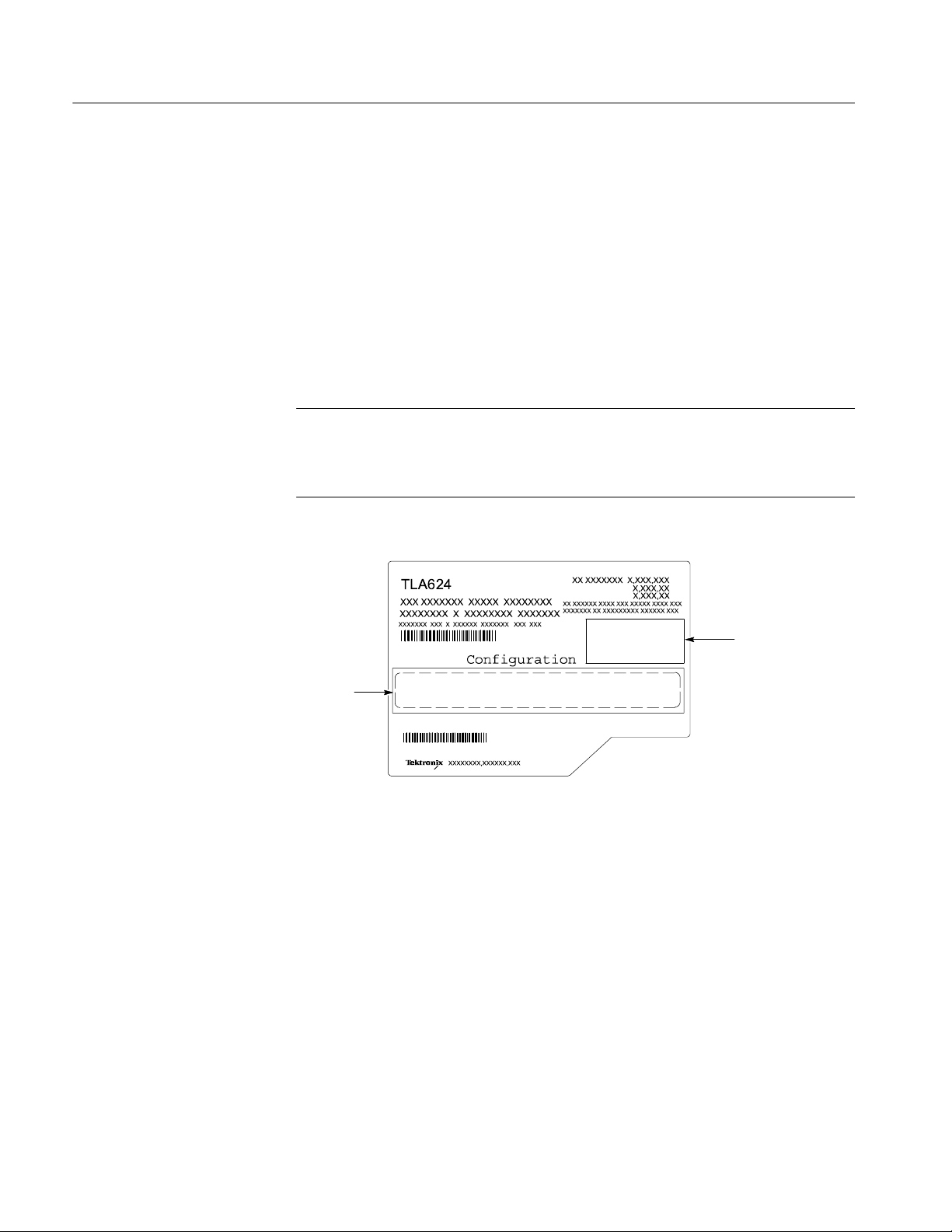
Attach the Upgrade Kit Label to the Instrument
After completing all the previous steps, you need to install the upgrade kit label
on the instrument to indicate that the kit is installed.
Locate the big label on the rear of the instrument, and then attach the TLA6UP
kit label as shown in Figure 1--7.
Kit label
Place revision
label here.
Figure 1--7: Kit label locations
1--22
TLA6UP Logic Analyzer Field Upgrade Kit Instruction Manual
Page 41

TLA6UP Option 15
Page 42

Page 43

TLA6UP Option 15: iView External Oscilloscope Cable Installation
TLA6UP option 15 provides the capability of connecting your logic analyzer to
an external Tektronix oscilloscope through the iView cable. Please order
TLA6UP Option 35 and 42 to get the latest TLA Application software.
Instruments
TLA600 Series Logic Analyzers All Serial Numbers
Minimum Tool and Equipment List
No special tools or equipment are required.
Parts List
Table 2--1: TLA6UP Option 15 parts list
Quantity Part number Description
1ea 012-1614-xx iView external oscilloscope cable kit
1ea N/A TLA6UP kit label
(includes USB-to-GPIB & BNC, BNC-to-SMB adapter, and
instruction card)
TLA6UP Logic Analyzer Field Upgrade Kit Instruction Manual
2--1
Page 44

TLA6UP Option 15: iView External Oscilloscope Cable Installation
Installation Prerequisite
Requires the latest TLA Application Software, Windows 2000 Professional
operating system, and 256 MB minimum mainframe memory (512 MB preferred).
Installation Instructions
Online installation instructions are provided within the TLA application through
a wizard. After powering on the instrument, select Add iView External Scope
from the System menu and follow the online instructions.
Attach the Upgrade Kit Label to the Instrument
After completing all the previous steps, you need to install the upgrade kit label
on the instrument to indicate that the kit is installed.
Locate the big label on the rear of the instrument, and then attach the TLA6UP
kit label as shown in Figure 2--1.
NOTE. If there is an upgrade kit label already installed, install the new label
above or below the old one, wherever there is room.
Revision Label
Kit label
Figure 2--1: Kit label locations
2--2
TLA6UP Logic Analyzer Field Upgrade Kit Instruction Manual
Page 45

TLA6UP Option 35
Page 46

Page 47

TLA6UP Option 35: Application Software and Windows Operating System Upgrade
TLA6UP option 35 supports the upgrade to TLA application software version 4.4
and Multi-language Windows 2000 Professional operating system (Service
Pack 4). TLA application software version 4.4 will only run on Tektronix
instruments with the Windows 2000 Professional operating system.
You can also use this kit to upgrade TLA600 series logic analyzers with TLA
application software 4.3 and below using the restore CD. This process overwrites
the entire contents of your hard disk drive. Therefore, you must back up any files
that you want to keep to backup media before beginning the upgrade procedure.
Instruments
TLA600 Series Logic Analyzers All Serial Numbers
System Requirements
H Minimum 10 GB hard drive
H 256 MB RAM minimum, 512 MB recommended
Minimum Tool and Equipment List
No special tools or equipment are required to install this option.
TLA6UP Logic Analyzer Field Upgrade Kit Instruction Manual
3--1
Page 48

TLA6UP Option 35: Application Software and Windows Operating System Upgrade
Parts List
Table 3--1: TLA6UP Option 35 parts list
Quantity Part number Description
1ea N/A Tektronix Logic Analyzer Family Application Software V4.4
(TLA App SW and TLAVu Offline software)
1ea N/A Tektronix Logic Analyzer Family TLA600 Restore Media
V4.4 (dual CD-ROM set)
1ea N/A Microsoft Windows 2000 Professional Certificate of
Authenticity
1ea N/A Microsoft Windows 2000 Professional license
1ea 016-1524-xx TLA mouse pad
1 sheet N/A Software revision labels
1ea N/A TLA6UP kit label
1ea N/A TLA600 BIOS floppy disk
1ea N/A IBM/Hitach HDD Feature Tool floppy disk
1ea N/A CheckIt Utilities sticker
1ea N/A Easy Restore license
1ea N/A RecordNow MAX license
3--2
TLA6UP Logic Analyzer Field Upgrade Kit Instruction Manual
Page 49

TLA6UP Option 35: Application Software and Windows Operating System Instructions
These instructions guide you through the process of upgrading your TLA600
series logic analyzer software and firmware. Software instructions describe the
process for upgrading to Windows 2000 Professional operating system and TLA
application software version 4.4.
CAUTION. The software installation procedure overwrites the entire contents of
your hard disk. If you want to save any files or software applications on the hard
disk, back them up to another media before continuing with this procedure.
In addition to the Tektronix Logic Analyzer application software, there are other
software programs that may be installed separately; Table 3--2 lists some of the
software that you may have installed on your logic analyzer.
Table 3--2: Software not covered by the software setup
Software Installation information
Microprocessor or bus support
software
Refer to the manual that was shipped with the microprocessor
or bus support.
Update the BIOS
PC Card Software Refer to the instructions that come with your PC Card.
Other Software Refer to the instructions that come with your software.
If you have just installed TLA6UP Option 10, you can skip this section and
continue with Install Software on page 3--4.
You may need to flash the logic analyzer controller BIOS with the latest flash
image before reinstalling software on the hard disk drive. To verify or update
your BIOS settings and the hard disk drive UDMA mode, refer to the following
procedures beginning on page 1--14 and then return to this section:
H Verify the TLA600 BIOS
H IBM\Hitachi HDD Feature Tool
TLA6UP Logic Analyzer Field Upgrade Kit Instruction Manual
3--3
Page 50

TLA6UP Option 35: Application Software and Windows Operating System Instructions
Install Software
The Tektronix Logic Analyzer field upgrade kit comes with restore media, which
contains Microsoft Windows 2000 Professional operating system and TLA
Application Software V4.4. All software required to run the logic analyzer comes
with the media, with the exception of any microprocessor support packages or
non-logic analyzer application software.
Back Up Files
Install Windows 2000
Professional and the TLA
Application Software
Before loading the restore media, back up any files, applications, and personal
files. Use the Windows Search utility to locate the files to back up. Table 3--3
lists examples of file suffixes that you may want to back up.
Table 3--3: TLA user file suffixes
Suffix Description
.tla TLA setup files and stored data
.tsf TLA symbol files
.tbf Tektronix binary format
.tls TLA script file
.tpg Tektronix pattern generator files
.txt Tektronix TLA data exchange format
files
.stk Stack files
.spz Protocol files
This procedure automatically reformats the hard disk, installs the Windows 2000
Professional Operating system software, and installs the the Tektronix Logic
Analyzer application software. This process may take several minutes.
3--4
Change the BIOS Boot Settings and Load the Restore Media. Before installing the
restore media, you must change the BIOS settings to enable booting from the
CD-ROM.
1. Restart the logic analyzer and then press function key F2 to enter the BIOS
setup.
2. In the BIOS setup, go to the Boot menu.
3. Select Boot Device Priority.
4. Set the Boot devices to boot from the CD first.
5. Insert the restore media in the CD-ROM drive.
TLA6UP Logic Analyzer Field Upgrade Kit Instruction Manual
Page 51

TLA6UP Option 35: Application Software and Windows Operating System Instructions
6. Save the settings by pressing function key F10 and press Enter to confirm
that you want to save the new settings. The instrument will reboot and begin
the installation procedure.
7. Review the license agreement. If you agree to the terms of the license
agreement, proceed with the next step.
8. Follow the on-screen instructions to complete the installation procedure.
If EasyRestore detects errors and prompts you to allow the program to fix
them, click Yes to continue the upgrade process.
NOTE. If you receive any warning or error messages indicating that new PCI
bridge devices were found, refer to PCI-VXI Bridge Driver Reinstallation on
page 3--6 for the proper action before continuing the next step. Otherwise,
continue with the next step.
9. Reinstall any user files that you backed up previously. Reinstall any software
(such as the microprocessor support packages) that you want to use on the
logic analyzer.
Reset the BIOS Boot Settings (Optional). After you have successfully installed the
software, if you wish to reset the BIOS settings and disable booting from
CD-ROM do the following, otherwise continue with PCI--VXI Bridge Driver
Reinstallation on page 3--6.
1. Restart the logic analyzer and then press function key F2 to enter the BIOS
setup.
2. In the BIOS setup, go to the Boot menu.
3. Set the Boot devices as shown below to disable booting from the CD-ROM:
First Boot Device: [Floppy]
Second Boot Device: [IDE-HDD]
Third Boot Device: [ATAPI CDROM]
4. Save the settings by pressing function key F10 and press Enter to confirm
that you want to save the new settings.
Once you have successfully reset the BIOS boot settings, you have completed the
operating system and TLA application software upgrade.
TLA6UP Logic Analyzer Field Upgrade Kit Instruction Manual
3--5
Page 52

TLA6UP Option 35: Application Software and Windows Operating System Instructions
PCI-VXI Bridge Driver Reinstallation. Some TLA600 systems are configured with
PCI devices that are not fully compatible with the restore media in this release.
The first time you boot your logic analyzer, you may receive several warning and
error messages indicating that new PCI devices were found and are being
installed.
Without confirming or closing the displayed messages, perform the following
steps:
1. Use your mouse to select and drag the messages to an alternate location on
your desktop, allowing access to the Insert Disk dialog.
2. Select the Insert Disk dialog and click the OK button. The system responds
by displaying the Files Needed dialog.
NOTE. You do not need to insert a CD labeled ”PCI--VXI Bridge Driver” into
your CD--ROM drive. Use the Files Needed dialog to specify the path to driver
information on your hard disk drive.
3. Select the Files Needed dialog and enter the following path information in
the Copy Files From field:
C:\WINNT\system32\drivers
4. Click the OK button. The system responds by installing the required PCI
bridge driver.
5. Reboot the logic analyzer and verify that no further warning or error
messages display.
Upon confirming that your system boots without error, return to the Reset the
BIOS Boot Settings procedure, step 10 located on page 3--5.
Upgrading to TLA Application Software V5.1
To upgrade the TLA application software to V5.1, install the upgrade kit label as
described under Attach the Upgrade Kit Label to the Instrument on page 3--8.
Then, follow the instructions for TLA6UP Option 42: Application Software
Upgrade beginning on page 4--1. Otherwise continue with the next section in this
document.
3--6
TLA6UP Logic Analyzer Field Upgrade Kit Instruction Manual
Page 53

TLA6UP Option 35: Application Software and Windows Operating System Instructions
Upgrade the TLA600 Firmware
Use the following procedure to upgrade the firmware for the TLA600 Series
Logic Analyzers. Complete the following steps if a startup message indicates that
you need to upgrade the firmware:
1. Disconnect any probes connected to the logic analyzer.
2. Exit the logic analyzer application.
3. Click Start → Programs → Tektronix Logic Analyzer → TLA Firmware
Loader.
4. You may see a pop-up window reminding you to cycle the power on the
mainframe after completing the upgrade operation. Click Yes to continue.
5. Select the module from the Supported list box near the top of the window.
6. Select Load Firmware from the Execute menu.
7. Click the TLA6xx.lod file.
Calibrate the Instrument
8. Click OK. When asked to confirm your action, click Yes.
9. When the firmware loading completes, exit the program, and power down
the logic analyzer. You must power down the logic analyzer to allow the
TLA application to start up properly.
After verifying proper operation you need to calibrate the logic analyzer.
1. Allow the instrument to warm up for at least 30 minutes before continuing.
2. In the System window, select Calibration and Diagnostics from the System
menu.
3. Click the Self Calibration tab.
4. Select the Run button and click Yes to any confirmation messages.
NOTE. The calibration process may take several minutes.
The Status column indicates Running while the instrument is being calibrated.
5. Verify that the Status column changes to Calibrated.
TLA6UP Logic Analyzer Field Upgrade Kit Instruction Manual
3--7
Page 54
TLA6UP Option 35: Application Software and Windows Operating System Instructions
6. After the instrument has been calibrated close the dialog box and power
down the instrument.
Attach the Upgrade Kit Label to the Instrument
After completing all the previous steps, you need to install the upgrade kit label
on the instrument to indicate that the kit is installed.
Locate the big label on the rear of the instrument and then attach the software
revision label and the TLA6UP kit label as shown in Figure 3--1.
NOTE. If there is an upgrade kit label already installed, install the new label just
above or below the old one, wherever there is room. However, ensure that you
install the software revision label over the old revision label to indicate the
current version of software on your instrument.
Kit label
Figure 3--1: Revision and kit label locations
Place revision
label here.
3--8
TLA6UP Logic Analyzer Field Upgrade Kit Instruction Manual
Page 55

TLA6UP Option 42
Page 56

Page 57

TLA6UP Option 42: Application Software Upgrade
TLA6UP option 42 supports the upgrade to TLA application software version 5.1
This kit provides instructions to upgrade the TLA application software and
firmware for a TLA600 Series logic analyzer with TLA application software
version 4.0 or higher. This software will only run on instruments with the
Windows 2000 Professional operating system purchased from Tektronix.
Instruments
System Requirements
TLA600 Series Logic Analyzers All serial numbers
H Minimum 10 GB hard drive
H 256 MB RAM minimum, 512 MB recommended
TLA6UP Logic Analyzer Field Upgrade Kit Instruction Manual
4--1
Page 58

TLA6UP Option 42: Application Software Upgrade
Parts List
Table 4--1: TLA6UP Option 42 parts list
Quantity Part number Description
1ea N/A Tektronix Logic Analyzer Family Application Software
1ea N/A Nero OEM Suite 3 CD
1ea 016-1524-xx TLA mouse pad
1 sheet N/A Software revision labels
1ea N/A TLA6UP kit label
Minimum Tool and Equipment List
No special tools or equipment are required to install this option.
Version 5.1
4--2
TLA6UP Logic Analyzer Field Upgrade Kit Instruction Manual
Page 59

TLA6UP Option 42: Application Software Instructions
The following instructions direct you through the process of upgrading the TLA
application software on your TLA600 series logic analyzer.
NOTE. Third-party software applications are included to use with your logic
analyzer. These applications may include software license agreements. Be sure to
abide by those license agreements.
Upgrade Instruction Overview
The basic upgrade procedure is to manually remove the older software, update
the drivers, and reinstall the new software. The upgrade steps are listed in this
document.
While performing the upgrade procedures, keep the following items in mind:
H Throughout this procedure you will see the term “log on as Administrator.”
The instrument is set up to automatically log on as Administrator (with no
password) so you may not see the log in prompt. If the network setups have
been changed on your instrument, make sure that you log on as Administrator or as a user who has administrator privileges. Failure to do so can prevent
the software upgrade from completing successfully.
H After logging on as administrator, quit any applications.
H If your instrument does not display the file extensions, you need to change
your folder options to display the file extensions. (From the Control Panel,
double-click Folder Options, select the View tab, and then deselect the “Hide
file extensions for known file types” selection.)
H Use the Windows Add or Remove Programs Control Panel utility to remove
existing software.
H You will be asked to restart Windows after you install each software
package. If you do not restart Windows when prompted your software may
not install properly and can cause unpredictable behavior.
H If Windows does not restart normally, press and hold the On/Standby button
for five or six seconds to force a shutdown.
TLA6UP Logic Analyzer Field Upgrade Kit Instruction Manual
4- 3
Page 60

TLA6UP Option 42: Application Software Instructions
Remove the Old Software
Complete the following steps to remove the old software packages from your
logic analyzer. Skip any steps that mention software that isn’t installed on your
logic analyzer.
NOTE. Refer to the release notes for a list of software version numbers to
determine which software you may need to upgrade. The release notes are
included on the TLA application software CD.
1. If you have not already done so, power on the logic analyzer and log on as
Administrator.
2. Exit the TLA application.
3. Open the Control Panel.
4. Double-click the Add or Remove Programs icon.
5. For each of the following software packages, select the software package (the
exact names may very depending on the software version), click the
Change/Remove button, and follow the on-screen instructions to remove the
software:
H Adobe Acrobat Reader
H CheckIt Utilities (V6.5.5)
H Logitech Mouseware (V9.41.2 or earlier)
H Click’N Burn Pro
H NI-488.2
H NI-Max
H QA+Win32
H SnagIt
H Stomp RecordNow MAX
H Macromedia Flash Media Player
H Tektronix TLA Application
4- 4
6. Windows will uninstall the selected application. If any messages appear
asking you for permission to remove unused shared files or any read-only
files, select Yes to All.
7. After the software has been successfully removed, restart Windows.
TLA6UP Logic Analyzer Field Upgrade Kit Instruction Manual
Page 61

Update the TLA Drivers
TLA6UP Option 42: Application Software Instructions
Complete the following steps to remove the old PCI--VXI Bridge driver and to
install the new one required by the TLA.
1. After rebooting the instrument, insert the second CD of the TLA Application
software set.
2. Open the Windows Control Panel.
3. Open the Device Manager in the Hardware page of the System Properties
dialog box.
4. Select PCI-VXI Bridge from the PciVxi listing.
5. Right-click to uninstall the device and then confirm that you want to delete
the device.
6. Restart the instrument.
After restarting, the instrument detects a new device and displays a dialog
box.
7. Click Cancel to exit the dialog box.
8. Open the Device Manager in the Hardware page of the System Properties
dialog box.
9. Under the PciVxi listing, Right-click Other PCI Bridge Device and select
Properties.
10. Select the Driver page and click Update Driver.
The Upgrade Device Driver Wizard displays.
11. Click Next.
12. In the Install Hardware Device Drivers page, select Search for a suitable
driver for my device (recommended) andthenclickNext.
13. In the Locate Drive Files page, select Specify a location and click Next.
14. Click Browse and go to the directory that contains the new pci2tla.inf driver
file. (D:\Drivers\your instrument\PCI--VXI Bridge\pci2tla.inf).
15. Select the pci2tla.inf driver and then click Open.
16. Click OK to install the driver.
17. In the Driver Files Search Results page, make sure that Install one of the
drivers checkbox is selected and then click Next.
18. Select the PCI to TLA Bridge driver and then click Next.
TLA6UP Logic Analyzer Field Upgrade Kit Instruction Manual
4- 5
Page 62

TLA6UP Option 42: Application Software Instructions
19. Click Finish to complete the installation.
20. Verify that the correct driver is installed by opening the Device Manager in
the System Properties dialog box.
Install Adobe Acrobat Reader
1. Log on as Administrator.
2. Install TLA V5.1 Application Software CD 1 in the CD drive.
3. Browse to the Documentation folder on the CD and double click AdbeRdr70_enu_full.exe.
4. Follow the on-screen instructions.
5. After the software has been successfully installed, restart Windows.
Install SnagIt
Install NI -GPIB
1. Log on as Administrator.
2. Browse to the SnagIt folder on the CD and double-click Setup.exe.
3. Follow the on-screen instructions and clear the check box for starting SnagIt
automatically. Use the remaining default choices provided by the installer.
4. After the software has been successfully installed, restart Windows.
1. Log on as Administrator.
2. Browse to the NI-GPIB-USB folder on the CD and run the Setup.exe
program.
3. Follow the on--screen instructions and note the items below:
a. When prompted, select the Typical installation option.
b. When the Add GPIB wizard appears, select GPIB-USB-B.
c. After restarting the instrument, the NI-488.2 Getting Started wizard
displays. This is not needed; select Do not show at Windows startup.
4- 6
d. When you first connect the iView cable, the instrument will detect the
new hardware. Select Install the software automatically (Recom-
mended).
TLA6UP Logic Analyzer Field Upgrade Kit Instruction Manual
Page 63

Install the TLA Software
TLA6UP Option 42: Application Software Instructions
The TLA software uses a wizard to install the following software applications (if
they are not already installed) for your instrument:
H TLA Application
H Pattern Generator Application
H Microsoft’s .NET Framework
H OpenChoice TekVisa
H TPI Client
H PPI Client
1. Log on as Administrator.
2. Browse to the TLA Application folder on the CD and double--click
Setup.exe.
Install CheckIt Utilities
3. Follow any on-screen instructions. If you are asked for permission to
overwrite any read-only files, select Yes to All.
4. After the software has been successfully installed, restart Windows.
1. Log on as Administrator.
2. Exit the TLA application.
3. Install TLA V5.1 Application Software CD 2 in the CD drive.
4. Browse to the CheckIt folder on the CD and double-click Start.exe.
5. Click Next to start the installation.
6. Read and accept the license agreement.
7. When prompted for the CheckIt serial number, use U7-999999.
8. Follow any on-screen instructions and use all of the default choices provided
by the installer.
9. Before clicking Finish, clear any check boxes that ask you to start the
application or to view the Readme file.
10. After the software has been successfully installed, restart Windows.
TLA6UP Logic Analyzer Field Upgrade Kit Instruction Manual
4- 7
Page 64

TLA6UP Option 42: Application Software Instructions
Install Flash Player
1. Log on as Administrator.
2. Exit the TLA application
3. Browse to the Macromedia folder on the CD and double-click flashplayer6_winax.exe.
4. Follow the on-screen instructions.
5. After the software has been successfully installed, restart Windows.
Install Logitech Mouseware
1. Log on as Administrator.
2. Exit the TLA application
3. Browse to the Mouseware folder on the CD and double-click Setup.exe.
4. Follow the on-screen instructions.
5. After the software has been successfully installed, restart Windows.
6. Follow the on-screen instructions in the Device Setup Wizard to set the
mouse to the factory recommended settings.
Install the Nero Suite 3 Software
The Nero OEM Suite software is available on a separate CD.
1. Log on as Administrator.
2. Exit the TLA application.
3. Insert the Nero CD into the CD drive.
4. Follow the on-screen instructions to install the software.
5. Enter the serial number when prompted (provided on the CD envelope).
6. Click Exit when done and then remove the CD.
7. Restart Windows.
4- 8
TLA6UP Logic Analyzer Field Upgrade Kit Instruction Manual
Page 65

Optional Software
TLA6UP Option 42: Application Software Instructions
Tektronix offers the following service-related software for running the performance verification software.
H TLACAL
You should only need to install this software if you are running performance
verification procedures with the appropriate test fixtures.
1. Log on as Administrator.
2. Exit the TLA application
3. Browse to the appropriate folder on the CD and double-click Setup.exe.
4. Follow the on-screen instructions.
5. After the software has been successfully installed, restart Windows.
Upgrade the TLA600 Firmware
Use the following procedure to upgrade the firmware for the TLA600 Series
Logic Analyzers. Complete the following steps if a startup message indicates
that you need to upgrade the firmware:
1. Log on to the instrument as Administrator.
2. Exit the logic analyzer application.
3. Click Start → Programs → Tektronix Logic Analyzer → TLA Firmware
Loader.
4. You may see a pop-up window reminding you to cycle the power on the
instrument after completing the upgrade operation. Click Yes to continue.
5. Select the module from the Supported list box near the top of the window.
6. Select Load Firmware from the Execute menu.
7. Click the TLA6xx.lod file.
8. Click OK. You will be asked to confirm your action; click Yes when
prompted.
9. Exit the firmware loader program and power down the logic analyzer. You
must power down the logic analyzer to allow the TLA application to start up
properly.
TLA6UP Logic Analyzer Field Upgrade Kit Instruction Manual
4- 9
Page 66

TLA6UP Option 42: Application Software Instructions
Calibrate the Logic Analyzer
After verifying proper operation calibrate the logic analyzer.
1. Allow the instrument to warm up for at least 30 minutes before continuing.
2. In the System window, select Calibration and Diagnostics from the System
menu.
3. Click the Self Calibration tab.
4. Select the Run button and click Yes to any confirmation messages.
NOTE. The calibration process may take several minutes.
The Status column should indicate Running while the instrument is being
calibrated.
5. Verify that the Status column changes to Calibrated.
6. After the instrument has been calibrated close the dialog box and power
down the instrument.
Installing the TLA Application Software on a PC
You can install the TLA application software on a PC for the following purposes:
H To run the TLA application software in the Offline mode (similar to TLAVu
or PatGenVu in earlier software versions).
H To control a logic analyzer with the same TLA application software version
over a network.
Install Third-Party
Software
To use all of the features of the TLA application software on your PC, you must
install additional third--party software. The following third--party software is
available on the TLA Application Software CD V5.1:
H The NI-GPIB-USB software allows you to use the iView software with your
PC.
H The SnagIt software is useful for copying screen shots of logic analyzer data
for use with other applications.
4- 10
TLA6UP Logic Analyzer Field Upgrade Kit Instruction Manual
Page 67

TLA6UP Option 42: Application Software Instructions
NOTE. Several third-party software applications are included to use with your
logic analyzer. These applications may include software license agreements. Be
sure to abide by those license agreements.
Complete the following steps to install the third--party software on your PC:
1. Install the TLA Application Software CD in the CD drive.
2. Browse to the NI-GPIB-USB folder on the CD and run the Setup.exe
program.
3. Follow the on--screen instructions and note the items below:
a. When prompted, select the Typical installation option.
b. When the Add GPIB wizard appears, select GPIB-- USB--B.
c. After restarting the instrument, the NI--488.2 Getting Started wizard
displays. This is not needed; select Do not show at Windows startup.
Install the TLA Application
Software
Start the TLA Application
d. When you first connect the iView cable, the instrument will detect the
new hardware. Select Install the software automatically (Recom-
mended).
4. Browse to the SnagIt folder on the CD and run the Setup.exe program.
Follow the on-screen instructions.
Browse to the TLA Application software folder on the CD and run the Setup.exe
program. Follow the on--screen instructions to install the software.
If you have an older version of the software on the hard disk, the installation
program will detect it and ask if you want to remove it. Follow the on-screen
instructions to remove the software, answering “Yes” to any prompts. Restart the
instrument when prompted and run the Setup.exe program again.
If you have installed the TLA application software on a PC for remote operation,
start the software by double-clicking on the TLA Application icon. The TLA
Connection dialog box displays.
1. Select an instrument in the TLA Connection dialog box and then click
Connect. If your instrument is connected to a network, you can connect to
any unused instrument on your local network.
2. Click Offline to start an offline version of the TLA application software. The
TLA Offline software allows you to run the TLA application without
connecting to an instrument. You can analyze previously acquired data from
a logic analyzer, create or modify reference memories, or perform system
tests without being connected to an instrument.
TLA6UP Logic Analyzer Field Upgrade Kit Instruction Manual
4- 11
Page 68
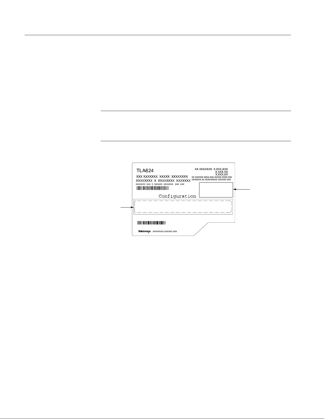
TLA6UP Option 42: Application Software Instructions
Attach the Upgrade Kit Label to the Instrument
After completing all the previous steps, you need to install the upgrade kit label
on the instrument to indicate that the kit is installed.
Locate the big label on the rear of the instrument and then attach the software
revision label and the TLA6UP kit label as shown in Figure 3--1.
NOTE. If there is an upgrade kit label already installed, install the new label just
above or below the old one, wherever there is room. However , ensure that you
install the software revision label over the old revision label to indicate the
current version of software on your instrument.
Kit label
Figure 4- 1: Revision and kit label locations
Place revision
label here.
4- 12
TLA6UP Logic Analyzer Field Upgrade Kit Instruction Manual
Page 69

TLA6UP Option PF
Page 70

Page 71

TLA6UP Option PF: PowerFlex Utility Upgrade
TLA6UP Option PF installs the TLA PowerFlex Utility on your TLA600 series
logic analyzer. You can use the PowerFlex Utility to determine possible upgrades
for your logic analyzer to increase your state speed or memory depth. The
PowerFlex Utility comes with online help that describes the upgrade processes.
The TLA PowerFlex Utility is installed on all TLA600 with TLA Application
Software Version 4.3 or later. You only need to order this upgrade if your
TLA600 has TLA Application Software Version 4.2 or earlier.
Instruments
TLA600 Series Logic Analyzers All Serial Numbers
Minimum Tool and Equipment List
No special tools or equipment are required to install this option. The PowerFlex
Utility software comes on a CD as a part of this upgrade kit.
Installation Prerequisite
Installation Instructions
No Requirements
Complete the following steps to install the PowerFlex Utility on your TLA600
series logic analyzer:
1. Install the PowerFlex CD in the CD drive of the TLA600 logic analyzer.
2. If required, log on to the instrument as Administrator.
3. Click Run in the Windows Start menu to display the Run dialog box.
4. Enter D:\PowerFlex\Disk 1\Setup.exe in the Run dialog box.
5. Follow the on-screen instructions. If any messages appear asking you for
permission to overwrite any read-only files, select Yes to All.
TLA6UP Logic Analyzer Field Upgrade Kit Instruction Manual
5--1
Page 72

TLA6UP Option PF: PowerFlex Utility Upgrade
Start the PowerFlex Utility
Complete the following steps to start and use the PowerFlex Utility:
NOTE. You must exit the TLA application before you start the PowerFlex Utility.
You cannot run the PowerFlex Utility and the TLA application at the same time.
1. Exit the TLA application.
2. Start the PowerFlex Utility using the Windows Start menu. Select Start →
Program Files → Tektronix Logic Analyzer → TLA PowerFlex Utility.
3. The PowerFlex window displays the current configuration of your logic
analyzer. Refer to the PowerFlex Utility online help for information on using
the utility to order and install the upgrade.
5--2
TLA6UP Logic Analyzer Field Upgrade Kit Instruction Manual
Page 73

TLA6UP Option IF
Page 74

Page 75

TLA6UP Option IF: Upgrade Installation Service
TLA6UP option IF provides installation of product upgrades performed at a
Tektronix service location.
NOTE. Availability of installation and on-site services depend on the type of
product and may vary by geography.
Instruments
TLA601 All Serial Numbers
TLA602 All Serial Numbers
TLA603 All Serial Numbers
TLA604 All Serial Numbers
TLA611 All Serial Numbers
TLA612 All Serial Numbers
TLA613 All Serial Numbers
TLA614 All Serial Numbers
TLA621 All Serial Numbers
TLA622 All Serial Numbers
TLA623 All Serial Numbers
TLA624 All Serial Numbers
TLA6UP Logic Analyzer Field Upgrade Kit Instruction Manual
6--1
Page 76

TLA6UP Option IF: Upgrade Installation Service
6--2
TLA6UP Logic Analyzer Field Upgrade Kit Instruction Manual
 Loading...