

Tektronix Logic Analyzer Series Reference manual

Technical Reference
Tektronix Logic Analyzer Series
Product Specifications
071-1344-02
This document applies to TLA System Software
version 4.3 and above.
www.tektronix.com
*P071134402*
071134402

Copyright © Tektronix, Inc. All rights reserved.
Tektronix products are covered by U.S. and foreign patents, issued and pending. Information in this publication supercedes
that in all previously published material. Spec ifications and price change privileges reserved.
Tektronix, Inc., P.O. Box 500, Beaverton, OR 97077
TEKTRONIX and TEK are registered trademarks of Tektronix, Inc.

Specifications and Characteristics
This document lists the specifications for the Tektronix Logic Analyzer family
products.
Characteristic Tables
All specifications are guaranteed unless noted Typical. Typical characteristics
describe typical or average performance and provide useful reference information.
Specifications that are marked with the n symbol are checked directly (or
indirectly) in the Performance Verification chapter of module’s or mainframe
service manual.
For mainframes and modules, the performance limits in this specification are
valid with these conditions:
H The logic analyzer must be in an environment with temperature, altitude,
humidity, and vibration within the operating limits described in these
specifications.
H The logic analyzer must have had a warm-up period of at least 30 minutes.
For modules, the performance limits in this specification are valid with these
conditions:
H The modules must be installed in a Logic Analyzer Mainframe.
H The module must have been calibrated/adjusted at an ambient temperature
between +20
H The DSO module must have had its signal-path-compensation routine
(self calibration or self cal) last executed after at least a 30 minute warm-up
period.
H After the warm-up period, the DSO module must have had its signal-path-
compensation routine last executed at an ambient temperature within ±5 _C
of the current ambient temperature.
For optimum performance using an external oscilloscope, please consult the
documentation for any external oscilloscopes used with your Tektronix Logic
Analyzer to determine the warm-up period and signal-path compensation
requirements.
_C and +30 _C.
TLA Specifications and Characteristics
1

Specifications and Characteristics
Atmospheric Characteristics for the Tektronix Logic Analyzer Family
Table 1 lists the Atmospheric characteristics of all components in the Tektronix
Logic Analyzer family.
Table 1: Atmospheric characteristics
Characteristic Description
Temperature:
Operating and nonoperating
Operating (no media in floppy disk drive):
+5 _Cto+50_C, 15 _C/hr maxim um gradient, non-condensing
(derated 1 _C per 1000 ft above 5000 foot altitude)
1
Nonoperating (no media in floppy disk drive or CD ROM drive):
-- 2 0 _Cto+60_C, 15 _C/hr maximum gradient, non-condensing.
Relative Humidity:
Operating and nonoperating
Altitude:
Operating and nonoperating
1
TLA7Axx series module operating temperature is +40 _C maximum.
2
TLA7Axx series module operating humidity is 5% to 90% up to +30 _C, 75% from +30 to +40 _C, noncondensing.
Maximum wet- bulb temperature is +29.4 _C.
3
TLA7NAx series module operating humidity is 5% to 90% up to +30 _C, 75% from +30 to +40 _C,45%from+40to
+50 _C, noncondensing. Maximum wet- bulb temperature is +29.4 _C.
4
TLA7Axx/TLA7NAx series module nonoperating humidity is 5% to 90% limited by a wet bulb temperature of
+40 _C.
Operating (no media in floppy disk drive or CD ROM drive):
20% to 80% relative humidity, non-condensing. Maximum wet bulb temperature: +29 _C
(derates relative humidity to approximately 22% at +50 _C)
.
2, 3
Nonoperating (no media in floppy disk drive or CD ROM drive):
8% to 80% relative humidity, non-condensing. Maximum wet bulb temperature: +29 _C (derates
relative humidity to approximately 22% at +50 _C).
4
Operating:
To 10,000 ft (3040 m), (derated 1 _C per 1000 ft (305 m) above 5000 ft
(1524 m) altitude)
Nonoperating:
40,000 ft (12190 m).
2
TLA Specifications and Characteristics

Certifications and Compliances
g
A
/
A
a
fetyreq
c
alequip
AdditionalComplianceIEC610101/A2:1995Safetyrequirementsforelectricalequipmentformeasurement
Table 2 lists the certifications and compliances of the Tektronix Logic Analyzer
family. The certifications and compliances apply to all components of the
Tektronix Logic Analyzer family unless noted otherwise.
Table 2: Certifications and compliances
Category Standards or description
Specifications and Characteristics
EC Declaration of Conformity -EMC
Australia / New Zealand
Declaration of Conformity-EMC
EC Declaration of Conformity -Low Voltage
U.S. Nationally Recognized
Testing Laboratory Listing
Canadian Certification CAN/CSA C22.2 No. 1010.1 Safety requirements for electrical equipment for measurement,
dditionalCompliance IEC61010-1
Meets intent of Directive 89/336/EEC for Electromagnetic Compatibility. Compliance was
demonstrated to the following specifications as listed in the Official Journal of the European
Communities:
EN 61326 EMC requirements for Class A electrical equipment for
measurement, control and laboratory use.
IEC 61000--4--2 Electrostatic discharge immunity (Performance criterion B)
IEC 61000--4--3 RF electromagnetic f ield im munity (Performance criterion A)
IEC 61000--4--4 Electrical fast transient / burst immunity (Performance criterion B)
IEC 61000--4--5 Power line surge immunity (Performance criterion B)
IEC 61000--4--6 Conducted RF immunity (Performance criterion A)
IEC 61000--4--11 Voltage dips and interruptions immunity (Performance criterion B)
EN 61000--3--2 AC power line harmonic emissions
Complies with EMC provision of Radiocommunications Act per the following standard(s):
AS/NZS 2064.1/2 Industrial, Scientific, and Medical Equipment: 1992
Compliance was demonstrated to the following specification as listed in the Official Journal of t he
European Communities:
Low Voltage Directive 73/23/EEC, amended by 93/68/EEC
EN 61010-1/A2:1995 Safety requirements for electrical equipment for measurement
control and laboratory use.
UL3111-1 Standard for electrical measuring and test equipment.
control, and laboratory use.
2:1995 S
control, and laboratory use.
uirementsfor electri
1
ment for measurement,
,
Installation (Overvoltage)
Category
1
Emissions which exceed the levels required by this standard may occur when this equipment is connected to a test
object.
TLA Specifications and Characteristics
Terminals on this product may have different installation (overvoltage) category designations. The
installation categories are:
CAT II Local-level mains (wall sockets). Equipment at this level includes appliances, portable
tools, and similar products. Equipm ent i s usuall y cord-connected.
3
Specifications and Characteristics
Table 2: Certifications and compliances (Cont.)
Category Standards or description
Pollution Degree A measure of the contaminates that could occur in the environment around and within a product.
Typically the internal environment inside a product is considered to be the same as the external.
Products should be used only in the environment for which they are rated.
Pollution Degree 2 Normally only dry, nonconductive pollut ion occurs. Occasionally a
temporary conductivity that is caused by condensation must be
expected. This location is a typical office/hom e environment.
Temporary condensation occurs only when the product is out of
service.
Safety Certification Compliance
Equipment Type Test and measuring
Safety Class Class 1 (as defined in IEC61010-1, Annex H) -- grounded product
Overvoltage Category Overvoltage Category II (as defined in IEC61010-1, Annex J)
Pollution Degree Pollution Degree 2 (as defined in IEC61010-1). Note: Rated for indoor use only.
4
TLA Specifications and Characteristics

TLA600 Series Logic Analyzer Specifications
Tables 3 through 17 list the specifications for the TLA600 series logic analyzer.
Table 3: TLA600 input parameters with probes
Characteristic Description
n Threshold Accuracy ±100 mV
Threshold range and step size Settable from +5 V to --2 V in 50 mV steps
Threshold channel selection 16 threshold groups assigned to channels.
P6417 and P6418 probes have two threshold settings, one for the clock/qualifier
channel and one for the data channels.
P6434 probes have four threshold settings, one for each of the clock/qualifier
channels and two for the data channels (one per 16 data channels).
n Channel-to-channel skew ≤ 1.6 ns maximum
Channel-to-channel skew
(Typical)
Sample uncertainty
Asynchronous: Sample period
Synchronous: 500 ps
Probe input resistance
(Typical)
Probe input capacitance: P6417, P6434
(Typical)
Probe input capacitance: P6418
(Typical)
Minimum slew rate
(Typical)
Maximum operating signal 6.5 V
Probe overdrive:
P6417, P6418
P6434
Maximum nondestructive input signal to probe ±15 V
Minimum input pulse width signal
(single channel)
(Typical)
Delay time from probe tip to input probe
connector
(Typical)
≤ 1.0 ns
20 kΩ
2pF
1.4 pF data channels
2 pF CLK/Qual channels
0.2 V/ns
p-p
--3.5 V absolute input voltage minimum
6.5 V absolute input voltage maximum
±250 mV or ±25% of signal swing minimum required beyond threshold, whichever is
greater
±300 mV or ±25% of signal swing minimum required beyond threshold, whichever is
greater
±4 V maximum beyond threshold
2ns
7.33 ns
Specifications and Characteristics
TLA Specifications and Characteristics
5

Specifications and Characteristics
Table 4: TLA600 timing latencies
Characteristic Description
System Trigger and External Signal Input
Latencies
1
(Typical)
External System Trigger Input to LA Probe
2
Tip
External Signal Input to LA Probe Tip via
Signal 3, 4
3
External Signal Input to LA Probe Tip via
Signal 1, 2
3, 4
--266 ns
--212 ns + Clk
--208 ns + Clk
System Trigger and External Signal Output
Latencies (Typical)
LA Probe Tip to External System Trigger
5
Out
376 ns + SMPL
LA Probe Tip to External Signal Out via
Signal 3, 4
5
OR function 366 ns + SMPL
AND function 379 ns + SMPL
LA Probe Tip to External Signal Out via
Signal 1, 2
4, 5
normal function 364 ns + SMPL
inverted logic on backplane 364 ns + SMPL
1
All system trigger and external signal input latencies are measured from a falling-edge transition (active true low) with
signals measured in the wired-OR configuration.
2
In the Waveform window, triggers are always marked immediately except when delayed to the first sample. In the Listing
window, triggers are always marked on the next sample period following their occurrence.
3
“Clk” represents the time to the next master clock at the destination logic analyzer. In the asynchronous (or internal)
clock mode, this represents the delta time to the next sample clock beyond the minimum asynchronous rate of 4 ns. In
the synchronous (or external) clock mode, this represents the time to the next master clock generated by the setup of the
clocking state machine and the supplied system under test clocks and qualification data.
4
Signals 1 and 2 (ECLTRG0, 1) are limited to a “broadcast” mode of operation, where only one source is allowed to drive
the signal node at any one time. That single source may be utilized to drive any combination of destinations.
5
SMPL represents the time from the event at the probe tip inputs to the next valid data sample. In the Normal Internal clock
mode, this represents the delta time to the next sample clock. In the MagniVu Internal clock mode, this represents 500 ps
or less. In the External clock mode, this represents the time to the next master clock generated by the setup of the
clocking state machine, the system-under-test supplied clocks, and the qualification data.
6
TLA Specifications and Characteristics

Specifications and Characteristics
Table 5: TLA600 external signal interface
Characteristic Description
System Trigger Input TTL compatible input via rear panel mounted BNC connectors
Input Levels
V
IH
V
IL
Input Mode Falling edge sensitive, latched (active low)
Minimum Pulse Width 12 ns
Active Period Accepts system triggers during valid acquisition periods via real-time gating, resets system
Maximum Input Voltage 0 to +5 V peak
External Signal Input TTL compatible input via rear panel mounted BNC connectors
Input Destination Signal 1, 2, 3, 4
Input Levels
V
IH
V
IL
Input Mode Active (true) low, level sensitive
Input Bandwidth
1
Signal 1, 2
Signal 3, 4
Active Period Accepts signals during valid acquisition periods via real-time gating
Maximum Input Voltage 0 to +5 V peak
System Trigger Output TTL compatible output via rear panel mounted BNC connectors
Source Mode Active (true) low, falling edge latched
Active Period Outputs system trigger state during valid acquisition period, resets system trigger output to false
Output Levels
V
OH
TTL compatible input
≥ 2.0 V
≤ 0.8 V
trigger input latch between valid acquisition periods
TTL compatible input
≥ 2.0 V
≤ 0.8 V
50 MHz square w ave minimum
10 MHz square w ave minimum
state between valid acquisitions
50 Ω back terminated TTL-compatible output
≥4 V into open circuit
≥ 2Vinto50Ω to ground
V
OL
≤ 0.7Vsinking10mA
Output Protection Short-circuit protected (to ground)
External Signal Output TTL compatible outputs via rear panel mounted BNC connectors
Source Selection Signal 1, 2, 3, 4, or 10 MHz clock
Output Modes
Level Sensitive
Output Levels
V
OH
User definable
Active (true) low or acti ve (true) high
50 Ohm back terminated TTL output
≥ 4 V into open circuit
≥ 2Vinto50Ω to ground
V
OL
≤ 0.7Vsinking10mA
TLA Specifications and Characteristics
7
Specifications and Characteristics
Table 5: TLA600 external signal interface (Cont.)
Characteristic Description
Output Bandwidth
Signal 1, 2
Signal 3, 4
Active Period Outputs signals during valid acquisition periods, resets signals to false state between valid
Output Protection Short-circuit protected (to ground)
1
The Input Bandwidth specification only applies to signals to the modules; it does not apply to signals applied to the
External Signal Input and sent back to the External Signal Output.
2
The Output Bandwidth specification only applies to signals from the modules; it does not apply to signals applied to the
External Signal Input and sent back to the External Signal Output.
2
50 MHz square w ave minimum
10 MHz square w ave minimum
acquisitions
Outputs 10 MHz clock continuously
Table 6: TLA600 channel width and depth
Characteristic Description
Number of channels Product Channels
TLA601, TLA611, TLA621 32 data and 2 clock
TLA602, TLA612, TLA622 64 data and 4 clock
TLA603, TLA613, TLA623 96 data, 4 clock, and 2 qualifier
TLA604, TLA614, TLA624 128 data, 4 clock, and 4 qualifier
Acquisition memory depth Product Memory depth
TLA601, TLA602, TLA603, TLA604 64 K or 256 K samples
TLA611, TLA612, TLA613, TLA614 64 K or 256 K samples
TLA621, TLA622, TLA623, TLA624 1 M samples
1
PowerFlex options
1
1
8
TLA Specifications and Characteristics
Table 7: TLA600 clocking
Characteristic Description
Asynchronous clocking
n Internal sampling period
n Minimum recognizable word
(across all channels)
Synchronous clocking
Number of clock channels
Number of qualifier channels
n Setup and hold window size
(data and qualifiers)
1
4 ns to 50 ms in a 1--2--5 sequence
2 ns in 2x Clocking mode
2
Channel-to-channel skew + sample uncertainty
Example: for a P6417, P6418, or P6434 Probe anda4nssampleperiod=
3
Product Clock channels
TLA601, TLA611, TLA621 2
TLA602, TLA612, TLA622 4
TLA603, TLA613, TLA623 4
TLA604, TLA614, TLA624 4
5
Product Qualifier channels
TLA601, TLA611, TLA621 0
TLA602, TLA612, TLA622 0
TLA603, TLA613, TLA623 2
TLA604, TLA614, TLA624 4
Maximum window size = Maximum channel-to-channel skew + (2 x sample
Maximum setup time = User interface setup time + 0.8 ns
Maximum hold time = User interface hold time + 0.2 ns
Specifications and Characteristics
1.6ns+4ns=5.6ns
uncertainty) + 0.4 ns
Examples: for a P6417 or a P6418 probe and user interface
setup and hold of 2.0/0.0 typical:
Maximum window size = 1.6 ns + (2 x 500 ps) + 0.4ns = 3.0 ns
Maximum setup time = 2.0 ns + 0.8 ns = 2.8 ns
Maximum hold time = 0.0 ns + 0.2 ns = 0.2ns
Setup and hold window size
(data and qualifiers)
(Typical)
Channel-to-channel skew (typical) + (2 x sample uncertainty)
Example: for P6417 or P6418 Probe = 1 ns + (2 x 500 ps) = 2 ns
Setup and hold window range For each channel, the setup and hold window can be moved from +8.5 ns (Ts) to
--7.0 ns (Ts) in 0.5 ns steps (setup time). Hold time follows the setup time by the setup
and hold window size.
n Maximum synchronous clock rate
4
200 MHz in full speed mode (5 ns minimum between active clock edges)
100 MHz (10 ns minimum between active clock edges)
Demux clocking
TLA603, TLA613, TLA623
TLA604, TLA614, TLA624
Channels multiplex as follows:
A3(7:0) to D3(7:0)
A2(7:0) to D2(7:0)
A1(7:0) to D1(7:0)
A0(7:0) to D0(7:0)
TLA Specifications and Characteristics
9
Specifications and Characteristics
Table 7: TLA600 clocking (Cont.)
Characteristic Description
TLA601, TLA611, TLA621
TLA602, TLA612, TLA622
Channels multiplex as follows:
A3(7:0) to C3(7:0)
A2(7:0) to C2(7:0)
A1(7:0) to D1(7:0) TLA602, TLA612, TLA622
A0(7:0) to D0(7:0) TLA602, TLA612, TLA622
Time between DeMux clock edges
(Typical)
Time between DeMux store clock edges
(Typical)
Data Rate
4
(Typical)
4
5 ns minimum between Demux clock edges in full-speed mode
10 ns minimum between Demux clock edges in half-speed mode
4
10 ns minimum between Demux master clock edges in full-speed mode
20 ns minimum between Demux master clock edges in half-speed mode
400 MHz (200 MHz option required) half channel.
(Requires channels to be multiplexed.)
These multiplexed channels double the memory depth.
Clocking state machine
Pipeline delays Each channel can be programmed with a pipeline delay of 0 through 3 active clock
edges.
1
It is possible to use storage control and only store data when it has changed (transitional storage).
2
Applies to asynchronous clocking only. Setup and hold window specification applies to synchronous clocking only.
3
Any or all of the clock channels may be enabled. For an enabled clock channel, either the rising, falling, or both edges
can be selected as the active clock edges. The clock channels are stored.
4
Full and half speed modes are controlled by PowerFlex options and upgrade kits.
5
All qualifier channels are stored. For custom clocking there are an additional 4 qualifier channels on C2 3:0 regardless of
channel width.
Table 8: TLA600 trigger system
Characteristic Description
Triggering Resources
Word/Range recognizers 16 word recognizers. The word recognizers can be combined to form full width, doubl e
bounded, range recognizers. The fol lowing selections are available:
16 word recognizers 0 range recognizers
13 word recognizers 1 range recognizer
10 word recognizers 2 range recognizers
7 word recognizers 3 range recognizers
4 word recognizers 4 range recognizers
Range recognizer channel order From most-significant probe group to least-significant probe group: C3 C2 C1 C0 E3
E2 E1 E0 A3 A2 D3 D2 A1 A0 D1 D0 Q3 Q2 Q1 Q0 CK3 CK2 CK1 CK0
Missing channels for modules with fewer than 136 channels are omitted.
Glitch detector
10
1,2
Each channel group can be enabled to detect a glitch
TLA Specifications and Characteristics

Table 8: TLA600 trigger system (Cont.)
Characteristic Description
Specifications and Characteristics
Minimum detectable glitch pulse width
2.0 ns (single channel with P6417, P6418, or a P6434 probe)
(Typical)
Setup and hold violation detector
1,3
Each channel can be enabled to detect a setup and hold violation. The range is from
8 ns before the clock edge to 8 ns after the cl ock edge. The range can be selected in
0.5 ns increments.
The setup and hold violation of each window can be individually programmed.
Transition detector
1
Each channel group can be enabled or disabled to detect a transition between the
current valid data sample and the previous valid data sample.
This mode can be used to create transitional storage selections where all channels
are enabled.
Counter/Timers 2 counter/timers, 51 bits wide, can be clocked up to 250 MHz.
Maximum count is 2
Maximum time is 9.007 X 10
51
.
6
seconds or 104 days.
Counters and timers can be set, reset, or tested and have zero reset latency.
External Signal In
1
A backplane input signal
External Trigger In A backplane input signal that causes the main acquisition and the MagniVu
acquisition to trigger if they are not already triggered
Active trigger resources 16 maximum (excluding counter/timers)
Word recognizers are traded off one-by-one as External Signal In, glitch detection,
setup and hold detection, or transition detect ion resources are added.
Trigger States 16
n Trigger State sequence rate Same rate as valid data samples received, 250 MHz maximum
Trigger Machine Actions
Main acquisition trigger Triggers the main acquisition memory
Main trigger position Trigger position is programmable to any data sample (4 ns boundaries)
MagniVut acquisi tion trigger Triggering of MagniV memory is controlled by t he mai n acquisition trigger
MagniVut trigger position The MagniV trigger position is programmable within 4 ns boundaries and separate
from the main acquisition memory trigger position.
Increment counter Either of the two counter/timers used as counters can be increased.
Start/Stop timer Either of the two counter/timers used as timers can be started or stopped.
Reset counter/timer Either of the two counter/timers can be reset.
When a counter/timer is used as a timer and is reset, the timer continues from the
started or stopped state that it was in prior to the reset.
Signal out A signal sent to the backplane to be used by other instruments
Trigger out A trigger out signal sent to t he backplane to trigger other instruments
TLA Specifications and Characteristics
11

Specifications and Characteristics
Table 8: TLA600 trigger system (Cont.)
Characteristic Description
Storage Control
Global storage Storage is allowed only when a specif ic condition is met. This condition can use any
of the trigger machine resources except for the counter/timers. Storage commands
defined in the current trigger state will override the global storage control.
Global storage can be used to start the acquisition with storage initially turned on
(default) or turned off.
By event Storage can be turned on or off; only the current sample can be stored. The event
storage control overrides any global storage commands.
Block storage When enabled, 31 samples are stored before and after the valid sample.
Not allowed when glitch storage or setup and hold violation is enabled.
Glitch violation storage The acquisition memory can be enabled to store glitch violation information with each
data sample when asynchronous clocking is used. The probe data storage size is
reduced by one half (the other half holds the violation information). The fastest
asynchronous clocking rate is reduced to 10 ns.
Setup and hold violation storage The acquisition memory can be enabled to store setup and hold violation information
with each data sample when synchronous clocki ng is used. The probe data storage
size is reduced by one half (the other half holds the violation information). The
maximum clock rate is reduced by half.
1
Each use of External Signal In, glitch detector, setup and hold violation detector, or transition detector requires a trade-off
of one word recognizer resource.
2
Any glitch is subject to pulse width variation of up to the channel-to-channel skew specification + 0.5 ns.
3
Any setup value is subject to variation of up to 1.8 ns; any hold value is subject to variation of up to 1.2 ns.
12
TLA Specifications and Characteristics
Specifications and Characteristics
Table 9: TLA600 MagniVut feature
Characteristic Description
MagniVu memory depth 2016 samples per channel
MagniVu sampling period Data is asynchronously sampled and stored every 500 ps in a separate high resolution
memory. There are no clocking options.
Table 10: TLA600 Data handling
Characteristic Description
Nonvolatile memory retention time
(Typical)
Battery is integral to the NVRAM. Battery life is > 10 years.
Table 11: TLA600 internal controller
Characteristic Description
Operating System Microsoft Windows
Microprocessor Intel Celeron, 566 MHz
Main Memory SDRAM
Style 168 pin DIMM, 2 Sockets
Speed 100 MHz
Installed Configurations Minimum 256 MB loaded in one socket
Maximum 512 MB with both sockets loaded
Real-Time Clock and CMOS Setups,
Plug & Play NVRAM Retention Time
Hard Disk Drive Standard PC compatible IDE (Integrated Device Electronics) hard disk drive residing on an
Size Minimum 10 GByte
Battery life is typic ally > 3 years when the logic analyzer is not connected to line voltage. When
connected to line voltage the life of the battery is extended.
Lithium battery, CR3032
EIDE interface.
Maximum 30 GByte
Continually subject to change due to the fast-moving PC component environment.
These storage capacities valid at product introduction.
CD-RW Drive Standard PC compatible IDE (Integrated Device Electronics)
24x-10x-40x CD-RW drive residing on an EIDE interface.
Continually subject to change due to the fast-moving PC component environment.
Floppy Disk Drive Standard 3.5 inch 1.44-MB PC compatible high-density, double-sided floppy disk drive.
TLA Specifications and Characteristics
13

Specifications and Characteristics
Table 12: TLA600 display system
Characteristic Description
Classification Standard PC graphics accelerator technology (bitBLT-based); capable of supporting both
internal color LCD display and external color SVGA/XGA monitor
Display Memory DRAM-based frame-buffer memory
Size 2 MB
Display Selection Both front panel and external displays can be used simultaneously, each with independent
resolutions. Supports Windows dual-moni tor capability.
External Display Drive One SVGA/XGA-compatible analog output port
Display Size Selected via Windows
Plug and Play support for DDC1 and DDC2 A and B
Resolution (Pixels) Colors
640 x 480 256, 64 K, 16.8 M
800 x 600 256, 64 K, 16.8 M
1024 x 768 256, 64 K, 8 M
1280 x 1024 256, 64 K, 8 M
Internal Display
Classification Thin Film Transistor (TFT) 10.4 inch active-matrix color LCD display; CCFL backlight; intensity
controllable via software
Resolution 800 x 600 pixels
Color Scale 262,144 colors (6-bit RGB)
Table 13: TLA600 front-panel interface
Characteristic Description
QWERTY Keypad ASCII keypad to support naming of files, traces, and keyboard equivalents of pointing device
inputs for menus
Special Function Knobs Various functions
14
TLA Specifications and Characteristics
Specifications and Characteristics
Table 14: TLA600 rear-panel interface
Characteristic Description
Parallel Interface Port (LPT) 36-pin high-density connector supports standard Centronics mode, Enhanced Parallel Port
(EPP), or Microsoft high-speed mode (ECP)
Serial Interface Port (COM 1) 9-pin male sub-D connector to support RS-232 serial port
Single USB Ports One USB (Universal Serial Bus) compliant port
SVGA Output Port (SVGA OUT) 15-pin sub-D SVGA connector
Mouse Port PS/2 compatible mouse port utilizing a mini DIN connector
Keyboard Port PS/2 compatible keyboard port utilizing a mini DIN connector
Type I and II PC Card Port Standard Type I and II PC-compatible PC card slot
Type I, II, and III PC Card Port Standard Type I, II , and III PC-compatible PC card slot
Table 15: TLA600 AC power source
Characteristic Description
Source Voltage and Frequency 90--250 V
100--132 V
45--66 Hz, continuous range CAT II
RMS,
360--440 Hz, continuous range CAT II
RMS,
Fuse Rating
90 V -- 132 V Operation
(2 required)
90 V - 250 V Operation
(2 required)
UL198/CSA C22.2
0.25 in × 1.25 in, Fast Blow, 8 A, 250 V
IEC 127/Sheet 1
5mm× 20 mm, Fast Blow, 6.3 A, 250 V
Maximum Power Consumption 600 Watts line power maximum
Steady-State Input Current 6A
RMS
maximum
Inrush Surge Current 70 A maximum
Power Factor Correction Yes
On/Standby Switch and Indicator Front Panel On/Standby switch, with indicator.
The power cord provides main power disconnect.
Table 16: TLA600 cooling
Characteristic Description
Cooling System Forced air circulation (negative pressurization) utilizing six fans operating in parallel
Cooling Clearance 2 in (51 mm), sides and rear; unit should be operated on a flat, unobstructed surface
TLA Specifications and Characteristics
15
Specifications and Characteristics
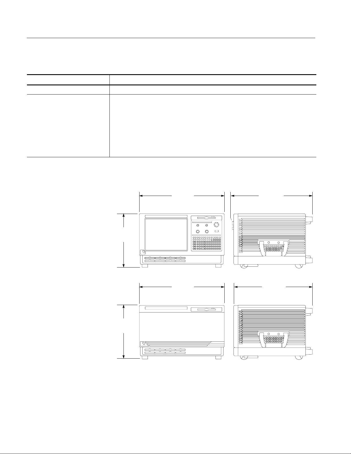
Table 17: TLA600 mechanical characteristics
Characteristic Description
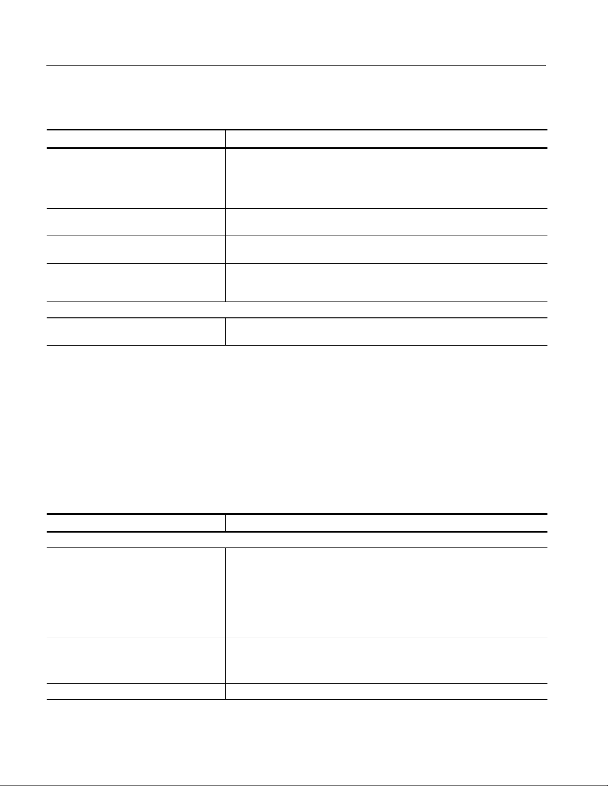
Overall Dimensions See Figure 1 for overall chassis dimensions
Weight Includes empty accessory pouch and front cover
TLA614, TLA624,
18.1 Kg (40 lbs)
TLA613, and TLA623
TLA612, TLA622,
18 Kg (39.75 lbs)
TLA611, and TLA621
TLA604 and TLA603 17.6 Kg (38.75 lbs)
TLA602 and TLA601 17.5 Kg (38.5 lbs)
281.94 mm
(11.10 in)
457.20 mm
(18.00 in)
421.64 mm
(16.60 in)
16
457.20 mm
(18.00 in)
281.94 mm
(11.10 in)
Figure 1: Dimensions of the TLA600 series logic analyzer
TLA Specifications and Characteristics
414.02 mm
(16.30 in)

TLA5000 Series Logic Analyzer Specifications
Tables 18 through 32 list the specifications for the TLA5000 series logic
analyzer.
Table 18: TLA5000 input parameters with probes
Characteristic Description
n Threshold Accuracy ±100 mV
Threshold range and step size Settablefrom+4.5Vto--2Vin5mVsteps
Threshold channel selection 16 threshold groups assigned to channels.
P6417, P6418 and P6419 probes have two threshold settings, one for the clock/qualifier channel and one for the data channels.
P6434 probes have four threshold settings, one for each of the clock/qualifier
channels and two for the data channels (one per 16 data channels).
n Channel-to-channel skew ≤ 1 ns maximum
Channel-to-channel skew
(Typical)
Sample uncertainty
Asynchronous: Sample period
Synchronous: 125 ps
Probe input resistance
(Typical)
Probe input capacitance: P6417, P6434
(Typical)
Probe input capacitance: P6418
(Typical)
P6419 input capacitance: P6419
(Typical)
Minimum slew rate
(Typical)
Maximum operating signal 6.0 V
Probe overdrive:
P6417, P6418, P6419
P6434
Maximum nondestructive input signal to probe ±15 V
≤ 0.9 ns
20 kΩ
2pF
1.4 pF data channels
2 pF CLK/Qual channels
<0.7pF
0.2 V/ns
p-p
--3.5 V absolute input voltage minimum
6.5 V absolute input voltage maximum
±250 mV or ±25% of signal swing minimum required beyond threshold, whichever is
greater
±300 mV or ±25% of signal swing minimum required beyond threshold, whichever is
greater
±4 V maximum beyond threshold
Specifications and Characteristics
TLA Specifications and Characteristics
17

Specifications and Characteristics
Table 18: TLA5000 input parameters with probes (Cont.)
Characteristic Description
Minimum input pulse width signal
(single channel)
1.5 ns (P6434)
1.25 ns (P6417, P6418, P6419)
(Typical)
Delay time from probe tip to module input
7.33 ns ±100ps
probe connector
(Typical)
Table 19: TLA5000 timing latencies
Characteristic Description
System Trigger and External Signal Input
Latencies
System Trigger and External Signal Output
Latencies (Typical)
1
(Typical)
External System Trigger Input to LA Probe
Tip
External Signal Input to LA Probe Tip via
Signal 3, 4
External Signal Input to LA Probe Tip via
Signal 1, 2
2
--594 ns
--594 ns + Clk
--594 ns + Clk
LA Probe Tip to External System Trigger
3
Out
760 ns + SMPL
LA Probe Tip to External Signal Out via
Signal 3, 4
3
OR function 760 ns + SMPL
AND function 760 ns + SMPL
LA Probe Tip to External Signal Out via
Signal 1, 2
2, 3
normal function 760 ns + SMPL
inverted logic on backplane 760 ns + SMPL
1
All system trigger and external signal input latencies are measured from a falling-edge transition (active true low) with
signals measured in the wired-OR configuration.
2
Signals 1 and 2 (ECLTRG0, 1) are limited to a “broadcast” mode of operation, where only one source is allowed to drive
the signal node at any one time. That single source may be utilized to drive any combination of destinations.
3
SMPL represents the time from the event at the probe tip inputs to the next valid data sample. In the Normal Internal clock
mode, this represents the delta time to the next sample clock. In the MagniVu Internal clock mode, this represents 500 ps
or less. In the External clock mode, this represents the time to the next master clock generated by the setup of the
clocking state machine, the system-under-test supplied clocks, and the qualification data.
18
TLA Specifications and Characteristics

Specifications and Characteristics
Table 20: TLA5000 external signal interface
Characteristic Description
System Trigger Input TTL compatible input via rear panel mounted BNC connectors
Input Levels
V
IH
V
IL
Input Mode Falling edge sensitive, latched (active low)
Minimum Pulse Width 12 ns
Active Period Accepts system triggers during valid acquisition periods via real-time gating, resets system
Maximum Input Voltage 0 to +5 V peak
External Signal Input TTL compatible input via rear panel mounted BNC connectors
Input Destination Signal 1, 2, 3, 4
Input Levels
V
IH
V
IL
Input Mode Active (true) low, level sensitive
Input Bandwidth
1
Signal 1, 2, 3, 4 50 MHz square wave minimum
Active Period Accepts signals during valid acquisition periods via real-time gating.
Maximum Input Voltage 0 to +5 V peak
System Trigger Output TTL compatible output via rear panel mounted BNC connectors
Source Mode Active (true) low, falling edge latched
Active Period Outputs system trigger state during valid acquisition period, resets system trigger output to false
Output Levels
V
OH
TTL compatible input
≥ 2.0 V
≤ 0.8 V
trigger input latch between valid acquisition periods.
TTL compatible input
≥ 2.0 V
≤ 0.8 V
state between valid acquisitions.
50 Ω back terminated TTL-compatible output
≥4 V into open circuit
≥ 2Vinto50Ω to ground
V
OL
≤ 0.7Vsinking10mA
Output Protection Short-circuit protected (to ground)
External Signal Output TTL compatible outputs via rear panel mounted BNC connectors
Source Selection Signal 1, 2, 3, 4, or 10 MHz clock
Output Modes
Level Sensitive
Output Levels
V
OH
User definable
Active (true) low or acti ve (true) high
50 Ohm back terminated TTL output
≥ 4 V into open circuit
≥ 2Vinto50Ω to ground
V
OL
Output Bandwidth
1
≤ 0.7Vsinking10mA
Signal 1, 2, 3, 4 50 MHz square wave minimum
TLA Specifications and Characteristics
19

Specifications and Characteristics
Table 20: TLA5000 external signal interface (Cont.)
Characteristic Description
Active Period Outputs signals during valid acquisition periods, resets signals to false state between valid
acquisitions.
Outputs 10 MHz clock continuously
Output Protection Short-circuit protected (to ground)
1
The Output Bandwidth specification only applies to signals from the modules; it does not apply to signals applied to the
External Signal Input and sent back to the External Signal Output.
Table 21: TLA5000 channel width and depth
Characteristic Description
Number of channels Product Channels
TLA5201 32 data and 2 clock
TLA5202 64 data and 4 clock
TLA5203 96 data, 4 clock, and 2 qualifier
TLA5204 128 data, 4 clock, and 4 qualifier
Acquisition memory depth Product Memory depth
TLA520X 512 K or optionally either 2 or 8 M samples
1
PowerFlex options
1
20
TLA Specifications and Characteristics

Specifications and Characteristics
Table 22: TLA5000 clocking
Characteristic Description
Asynchronous clocking
n Internal sampling period
n Minimum recognizable word
(across all channels)
Synchronous clocking
Number of clock channels
Number of qualifier channels
n Setup and hold window size
(data and qualifiers)
Setup and hold window size
(data and qualifiers)
(Typical)
Setup and hold window range For each channel, the setup and hold window can be moved from +8.0 ns (Ts) to
n Maximum synchronous clock rate 235 MHz in full speed mode (4. 25 ns minimum bet ween active clock edges)
1
500 ps to 50 ms in a 1-2-5 sequence. Storage control can be used to only store data
when it has changed (transitional storage)
2 ns minimum for all channels
1 ns minimum for half channels (using 2:1 demultiplex mode)
0.5 ns minimum for quarter channels (using 4:1 demultiplex mode)
2
Channel-to-channel skew + sample uncertainty
Example: for a P6419, or P6434 Probe anda2nssampleperiod=
1ns+2ns=3ns
3
Product Clock channels
TLA5201 2
TLA5202 4
TLA5203 4
TLA5204 4
4
Product Qualifier channels
TLA5201 0
TLA5202 0
TLA5203 2
TLA5204 4
Maximum window size = Maximum channel-to-channel skew + (2 x sample
uncertainty) + Margin = 1.875 ns
Channel-to-channel skew (typical) + (2 x sample uncertainty) = 1.5 ns
--8.0 ns (Ts) in 0.125 ns steps (setup time). Hold time follows the setup time by the
setup and hold window size.
TLA Specifications and Characteristics
21

Specifications and Characteristics
Table 22: TLA5000 clocking (Cont.)
Characteristic Description
2X Demux clocking
TLA5203
TLA5204
TLA5201
TLA5202
Time between Demultiplex clock edges
(Typical)
4X Demux clocking
TLA5203
TLA5204
TLA5201
TLA5202
Time between Demultiplex clock edges
(Typical)
Any individual channel may be demultiplexed wit h it s partner channel. Channels
demultiplex as folllows:
A3(7:0) to/from D3(7:0)
A2(7:0) to/from D2(7:0)
A1(7:0) to/from D1(7:0)
A0(7:0) to/from D0(7:0)
C3(7:0) to/from C1(7:0)
C2(7:0) to/from C0(7:0)
E3(7:0) to/from E1(7:0) TLA5204 only
E2(7:0) to/from E0(7:0) TLA5204 only
CK3 to/from Q2 TLA5204 only
CK2 to/from Q3) TLA5204 only
CK1 to/from Q0
CK0 to/from Q1
Any individual channel may be demultiplexed wit h it s partner channel. Channels
demultiplex as folllows:
A3(7:0) to/from C3(7:0)
A2(7:0) to/from C2(7:0)
A1(7:0) to/from D1(7:0) TLA5202 only
A0(7:0) to/from D0(7:0) TLA5202 only
Same limitations as normal synchronous acquisition
Unlike 2X demultiplexing, the channels within a group of four cannot arbitrarily drive
the others.
E3(7:0) to E2(7:0), E1(7:0), E0(7:0) TLA5204 only
A3(7:0) to A2(7:0), D3(7:0), D2(7:0)
A1(7:0) to A0(7:0), D1(7:0), D0(7:0)
C3(7:0) to C2(7:0), C1(7:0), C0(7:0)
CK3 to CK2, Q3, Q2 TLA5204 only
CK1 to CK0, Q1, Q0
Unlike 2X demultiplexing, the channels within a group of four cannot arbitrarily drive
the others.
A1(7:0) to A0(7:0), D1(7:0), D0(7:0) TL:A5202 only
C3(7:0) to C2(7:0), A3(7:0), A2(7:0)
Same limitations as normal synchronous acquisition
22
TLA Specifications and Characteristics

Specifications and Characteristics
Table 22: TLA5000 clocking (Cont.)
Characteristic Description
Clocking state machine
Pipeline delays Each channel can be programmed with a pipeline delay of 0 through 7 active clock
edges.
1
It is possible to use storage control and only store data when it has changed (transitional storage).
2
Applies to asynchronous clocking only. Setup and hold window specification applies to synchronous clocking only.
3
Any or all of the clock channels may be enabled. For an enabled clock channel, either the rising, falling, or both edges
can be selected as the active clock edges. The clock channels are stored.
4
All qualifier channels are stored. For custom clocking there are an additional 4 qualifier channels on C2 3:0 regardless of
channel width.
Table 23: TLA5000 trigger system
Characteristic Description
Triggering Resources
Word/Range recognizers 16 word recognizers. The word recognizers can be combined to form full width, doubl e
bounded, range recognizers. The fol lowing selections are available:
16 word recognizers 0 range recognizers
13 word recognizers 1 range recognizer
10 word recognizers 2 range recognizers
7 word recognizers 3 range recognizers
4 word recognizers 4 range recognizers
Range recognizer channel order From most-significant probe group to least-significant probe group: C3 C2 C1 C0 E3
E2 E1 E0 A3 A2 D3 D2 A1 A0 D1 D0 Q3 Q2 Q1 Q0 CK3 CK2 CK1 CK0
Missing channels for modules with fewer than 136 channels are omitted.
Glitch detector
1,2
Channel groups can be enabled to detect glitches.
Glitches are subject to pulse width variations of up to ±125 ps
Minimum detectable glitch pulse width
(Typical)
Setup and hold violation detector
1,3
1.25 ns (single channel with P6434 probe)
1.0 ns (P6417, P6418, P6419 probe)
Any channel can be enabled to detect a setup or hold violation. The range is from 8.0
ns before the clock edge to 8.0 ns after the clock edge in 0.125 ns steps. The channel
setup and hold violation size can be individually programmed.
The range can be shifted towards the positive region by 0 ns, 4 ns, or 8 ns. With a 0
ns shift, the range is +8 ns to --8 ns; witha4nsshift,therange is +12 ns to --4 ns;
with an 8 ns shift, the range is +16 ns to 0 ns. The sample point selection region is the
same as the setup and hol d window.
TLA Specifications and Characteristics
Any setup value is subject to variation of up to the channel skew specification. Any
hold value is subject to variation of up to the channel skew specification.
23

Specifications and Characteristics
Table 23: TLA5000 trigger system (Cont.)
Characteristic Description
Transition detector
Counter/Timers 2 counter/timers, 51 bits wide, can be clocked up to 500 MHz.
External Signal In
External Trigger In A backplane input signal that causes both the main acquisition and the MagniVu
Active trigger resources 16 maximum (excluding counter/timers)
Trigger States 16
n Trigger State sequence rate Same rate as valid data samples received, 500 MHz maximum.
Trigger Machine Actions
Main acquisition trigger Triggers the main acquisition memory.
Main trigger position Trigger position is programmable to any data sample (2 ns boundaries).
MagniVut acquisi tion trigger Triggering of MagniV memory is controlled by t he mai n acquisition trigger machine.
MagniVut trigger position The MagniV trigger position is programmable within 2 ns boundaries and separate
Increment & decrement counter Either of the two counter/timers used as counters can be increased or decreased.
Reloadable word recognizer Loads the current acquired data sample into the reference value of the word
Reloadable word recognizer latency 378 ns
Start/Stop timer Either of the two counter/timers used as timers can be started or stopped.
Reset counter/timer Either of the two counter/timers can be reset.
1
16 transition detectors.
Any channel group can be enabled or disabled to detect a rising transition, a falling
transition, or both rising and falling transitions between the current valid data sample
and the previous valid data sample.
51
Maximum count is 2
Maximum time is 4.5 X 10
-- 1 .
6
seconds or 52 days.
Counters and timers can be set, reset, or tested and have zero reset latency.
1
A backplane input signal.
acquisition to trigger if they are not already triggered.
Word recognizers are traded off one-by-one as External Signal In, glitch detection,
setup and hold detection, or transition detect ion resources are added.
from the main acquisition memory trigger position.
recognizer via a trigger machine action. All data channels are loaded into their
respective word recognizer reference register on a one-to-one manner.
When a counter/timer is used as a timer and is reset, the timer continues from the
started or stopped state that it was in prior to the reset.
Signal out A signal sent to the backplane to be used by other instruments.
Trigger out A trigger out signal sent to t he backplane to trigger other instruments.
24
TLA Specifications and Characteristics
 Loading...