


xx
TBS1000 Series
ZZZ
Digital Storage Oscilloscopes
Installation and Safety Manual
*P071309901*
071-3099-01


xx
TBS1000 Series
ZZZ
Digital Storage Oscilloscopes
Installation and Safety Manual
www.tektronix.com
071-3099-01

Copyright © Tektronix. All rights reserved. Licensed software products are owned by Tektronix or its subsidiaries
or suppliers, and are protected by national copyright laws and international treaty provisions.
Tektronix products are covered by U.S. and foreign patents, issued and pending. Information in this publication
supersedes that in all previously published material. Specifications and price change privileges reserved.
TEKTRONIX and TEK are registered trademarks of Tektronix, Inc.
OpenChoice™ is a registered trademark of Tektronix, Inc.
Contacting Tektronix
Tektronix, Inc.
14150 SW Karl Braun Drive
P.O . Bo x 5 0 0
Beaverton, OR 97077
USA
For product information, sales, service, and technical support:
In North America, call 1-800-833-9200.
Worl d wide , vi sit www.tektronix.com to find contacts in your area.

Table of Contents
General Safety Summary .......................................................................................... 1
Compliance Information........................................................................................... 3
EMC Compliance. .................................. ................................ ........................... 3
Safety Compliance............................................................................................. 5
Environmental Considerations ................................ .................................. ............. 6
Getting Started . . ... ... ... . ... ... . .. . ... ... . .. . ... ... . ... ... ... . ... ... . ... ... ... . ... ... ... . ... ... . .. . ... ... . ... ... ... 7
Installation..................... ................................ .................................. ............... 7
Functional Check .............................................................................................. 8
Probe Safety ......................... ................................ .................................. ......... 9
Voltage Probe Check Wizard ................................................................................. 9
Manual Probe Compensation................................................................................ 11
Probe Attenuation Setting. ... ... . .. . ... ... . .. . ... ... ... . ... ... ... . ... ... ... ... . ... ... ... . .. . ... ... . .. . ... ... . 11
Current Probe Scaling ........................................................................................ 12
Self Calibration . ................................ .................................. ............................ 12
Firmware Updates Through the Internet ................... ................................ ................ 13
Operating Basics................................................................................................... 14
Display Area .................................................................................................. 15
Using the Menu System...................................... ................................ ................ 17
Vertical Controls ...................... ................................ ................................ ........ 19
Horizontal Controls........................................................................................... 19
Trigger Controls............................................................................................... 20
Menu and Control Buttons................................................................................... 21
Input Connectors.............................................................................................. 23
Other Front-Panel Items...................................................................................... 23
Installing the PC Communications Software on a PC . ... .. .. . ... ... . .. . ... ... . ... ... ... . ... ... . . .. . ... .. 24
Connecting to a PC ........................................................................................... 24
Specifications ............ ................................ .................................. ........................ 27
Oscilloscope Specifications............................ .................................. .................... 27
TPP0101 and TPP0201 Series 10X Passive Probes Information. ................................ ............ 29
Connecting the Probe to the Oscilloscope . . ... ... ... ... . .. . ... ... ... . ... ... ... ... . ... ... ... . .. . ... ... ... .. 29
Compensating the Probe .................................................................................... 29
Connecting the Probe to the Circuit ........................................................................ 30
Standard Accessories......................................................................................... 31
Optional Accessories......................................................................................... 32
Specifications........................ .................................. ................................ ........ 32
Performance Graphs.......... .................................. ................................ .............. 33
Safety Summary .............................................................................................. 34
TBS1000 Series Oscilloscopes Installation and Safety Manual i

Table of Contents
Accessories..................... ................................ ................................ .................... 36
Cleaning ...... ................................ ................................ .................................. .... 38
General Care .................................................................................................. 38
Cleaning ....................................................................................................... 38
Font Licenses .... ................................ ................................ .................................. 39
安全にご使用いただくために .......................................................................... 41
適合性に関する情報.................................................................................... 43
EMC .............................. ................................ ................................ .............. 43
安全性 ............................................................................................... 44
環境条件について.................................................................................. 45
はじめに.................................................................................................. 46
設置.................................................................................................. 46
機能チェック......................................................................................... 47
プローブの安全性 .................................................................................. 48
電圧プローブ・チェック・ウィザード ................................................................ 48
プローブの手動補正 ............................................................................... 50
プローブの減衰設定 ............................................................................... 51
電流プローブ・スケール ............................................................................ 51
自己校正 ............................................................................................ 52
インターネット経由のファームウェア更新 ......................................................... 52
基本操作................................................................................................. 53
表示領域 ............................................................................................ 54
メニュー・システムの使用........................................................................... 57
垂直軸コントロール ................................................................................. 58
水平軸コントロール ................................................................................. 59
トリガ・コントロール .................................................................................. 60
メニュー・ボタンとコントロール・ボタン ............................................................. 60
入力コネクタ......................................................................................... 63
フロント・パネルのその他のコネクタ ............................................................... 63
PC への PC 通信ソフトウェアのインストール ...................................................... 64
PC への接続 ........................................................................................ 65
仕様 ...................................................................................................... 68
オシロスコープの仕様 .............................................................................. 68
TPP0101 および TPP0201 シリーズ受動プローブ(100 MHz/200 MHz 10X)に関する情報 ....... 69
プローブとオシロスコープの接続.................................................................. 70
プローブの補正 ............................................................................................. 70
プローブと測定回路の接続 ........................................................................ 71
スタンダード・アクセサリ ............................................................................ 72
オプショナル・アクセサリ............................................................................ 73
仕様.................................................................................................. 73
性能グラフ ........................................................................................... 74
ii TBS1000 Series Oscilloscopes Installation and Safety Manual

Table of Contents
安全にご使用いただくために
アクセサリ ................................................................................................ 77
クリーニング .............................................................................................. 79
一般的な注意事項.................................................................................. 79
クリーニング ......................................................................................... 79
フォントのライセンス ..................................................................................... 80
常规安全概要 ........................................................................................... 82
符合性信息 .............................................................................................. 83
EMC 符合性 .......................................................................................... 83
安全符合性.......................................................................................... 84
环境注意事项....................................................................................... 86
入门 ...................................................................................................... 87
安装 .................................................................................................. 87
功能检查 ............................................................................................ 88
探头安全性.......................................................................................... 88
电压探头检查向导 ................................................................................. 89
手动探头补偿....................................................................................... 90
探头衰减设置....................................................................................... 91
电流探头标度....................................................................................... 91
自校正 ............................................................................................... 91
通过 Internet 更新固件 ......................................................................... 92
基本操作................................................................................................. 93
显示区域 ............................................................................................ 94
使用菜单系统....................................................................................... 96
垂直控制 ............................................................................................ 97
水平控制 ............................................................................................ 98
“触发”控制 ....................................................................................... 99
菜单和控制按钮 .................................................................................... 99
输入连接器......................................................................................... 101
其他前面板项...................................................................................... 102
在 PC 上安装 PC Communications 软件 ....................................................... 102
连接到 PC................................................................................................... 103
技术规格................................................................................................ 106
示波器技术规格 ................................................................................... 106
TPP0101 及 TPP0201 系列 100 及 200 MHz 10X 无源探头信息 ................................. 107
将探头连接到示波器 ............................................................................. 108
补偿探头 ........................ ................................ ................................ .......... 108
将探头连接到电路 ................................................................................ 109
标准附件 ........................................................................................... 110
可选附件 ........................................................................................... 111
技术规格 ........................................................................................... 111
...................................................................... 75
TBS1000 Series Oscilloscopes Installation and Safety Manual iii

Table of Contents
性能图 .............................................................................................. 112
安全概要 ........................................................................................... 113
附件 ..................................................................................................... 115
清洁 ..................................................................................................... 117
日常保养 ........................................................................................... 117
清洁 ................................................................................................. 117
字体许可证 ............................................................................................. 118
iv TBS1000 Series Oscilloscopes Installation and Safety Manual

General Safety Summary
Review the following safety precautions to avoid injury and prevent damage to
this product or any products connected to it.
To avoid potential hazards, use this product only as specified.
Only qualified personnel should perform service procedures.
To Avoid Fire or Personal
Injury
Use Proper Power Cord. Use only the power cord specified for this product and
certified f
Connect and Disconnect Properly. Connect the probe output to the measurement
instrument before connecting the probe to the circuit under test. Connect the
probe reference lead to the circuit under test before connecting the probe input.
Disconnect the probe input and the probe reference lead from the circuit under test
before
Ground the Product. This product is grounded through the grounding conductor
of the power cord. To avoid electric shock, the grounding conductor must be
connected to earth ground. Before making connections to the input or output
terminals of the product, ensure that the product is properly grounded.
Observe All Terminal Ratings. To a v oi d fire or shock hazard, observe a ll ratings
and markings on the product. Consult the product manual for further ratings
information before making connections to the product.
Connect the probe reference lead to earth ground only.
Do not apply a potential to any terminal, including the common terminal, that
exceeds the maximum rating of that terminal.
Power Disconnect. The power switch disconnects the product from the power
source. See instructions for the location. Do not block the power switch; it must
emain accessible to the user at all times.
r
or the country of use.
disconnecting the probe from the measurement instrument.
Do Not Operate Without Covers. Do not operate this product with covers or
panels removed.
Do Not Operate With Suspected Failures. If you suspect that there is damage to
this product, have it inspected by qualified service personne l .
Avoid Exposed Circuitry. Do not touch exposed connections and components
when power is present.
TBS1000 Series Oscilloscopes Installation and Safety Manual 1
General Safety Summary
TermsinthisManual
Symbols and Terms on the
Product
Do Not Operate i
Do Not Operate in an Explosive Atmosphere.
Keep Product Surfaces Clean and Dry.
Provide Prop
details on installing the product so it has proper ventilation.
These terms may appear in this manual:
WARNING.
in injury or loss of life.
CAUTION
damage to this product or other property.
These t
. Caution statements identify conditions or practices that could result in
erms may appear on the product:
DANGER indicates an injury hazard immediately accessible as you read
the ma
n Wet/Damp Conditions.
er Ventilation. Refer to the manual's installation instructions for
Wa rning statements identify conditions or practices that could result
rking.
WARNING indicates an injury hazard not immediately accessible as you
the marking.
read
CAUTION indicates a hazard to property including the product.
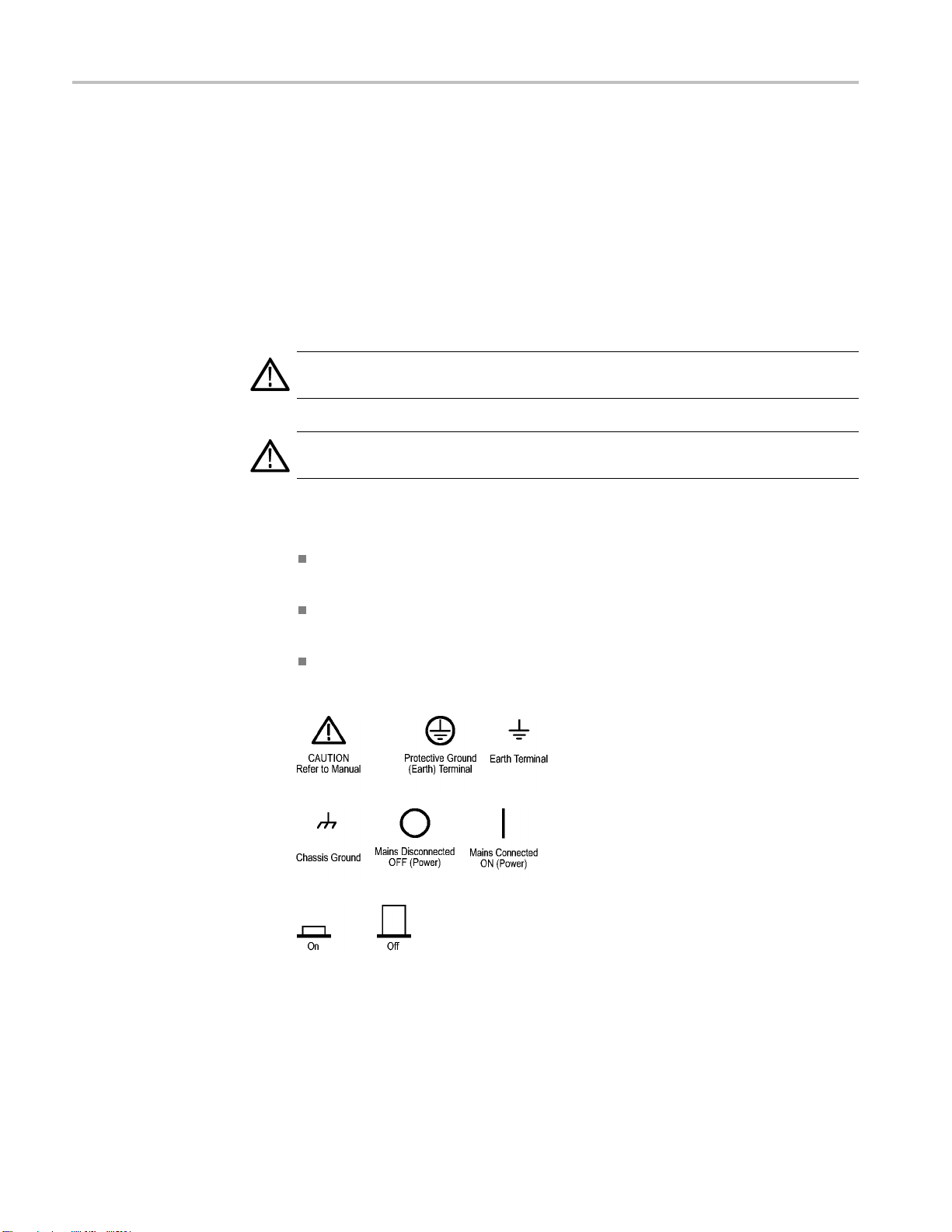
The following symbol(s) may appear on the product:
2 TBS1000 Series Oscilloscopes Installation and Safety Manual

Compliance Information
Compliance In
EMC Compliance
EC Declaration of
Conformity – EMC
formation
This section
environmental standards with which the instrument complies.
Meets intent of Directive 2004/108/EC for Electromagnetic Compatibility.
Compliance was demonstrated to the following specifications as listed in the
Official Journal of the European Communities:
EN 61326-1:2006, EN 61326-2-1:2006. EMC requirements for electrical equipment
for meas
CISPR 11:2003. Radiated and conducted emissions, Group 1, Class A
IEC 61000-4-2:2001. Electrostatic discharge immunity
IEC 61000-4-3:2002. RF electromagnetic field immunity
IEC 61000-4-4:2004. Electrical fast transient/burst immunity
IEC 61000-4-5:2001. Power line surge immunity
lists the EMC (electromagnetic compliance), safety, and
urement, control, and laboratory use.
123
4
1000-4-6:2003. Conducted RF immunity
IEC 6
IEC 61000-4-11:2004. Voltage dips and interruptions immunity
EN 61000-3-2:2006. AC power line harmonic emissions
EN 61000-3-3:1995. Voltage changes, fluctuations, and flicker
5
6
TBS1000 Series Oscilloscopes Installation and Safety Manual 3

Compliance Information
Australia
/ New Zealand
Declaration of
Conformity – EMC
European Conta
ct.
Tektronix UK, Ltd.
Western Peninsula
Western Road
Bracknell, RG12 1RF
United Kingdom
1
This product is intended for use in nonresidential areas only. Use in residential areas may cause electromagnetic
interference.
2
Emissions which exceed the levels required by this standard may occur when this equipment is connected to a
test object.
3
To ensure compliance with the EMC standards listed here, high quality shielded interface cables should be used.
4
The instrument will exhibit ≤ 1.0 division waveform displacement and ≤ 2.0 division increase in peak-to-peak
noise when subjected to radiated interference per IEC 61000-4-3.
5
The instrument will exhibit ≤ 0.5 division waveform displacement and ≤ 1.0 division increase in peak-to-peak
noise when subjected to conducted interference per IEC 61000-4-6.
6
Performance Criterion C applied at the 70%/25 cycle Voltage-Dip and the 0%/250 cycle Voltage-Interruption test
levels (IEC 61000-4-11). If the instrument powers down upon a voltage dip or interruption, it will take longer than
ten seconds to return to the previous operating state.
Complies with the EMC provision of the Radiocommunications Act per the
following standard, in accordance with ACMA:
CISPR 11:2003. Radiated and Conducted Emissions, Group 1, Class A, in
accordance with EN 61326-1:2006 and EN 61326-2-1:2006.
4 TBS1000 Series Oscilloscopes Installation and Safety Manual

Compliance Information
Safety Compli
ance
EC Declaration of
Conformity – Low Voltage
U.S. Natio
nally Recognized
Testing Laboratory Listing
Canadian Certification
Additional Compliances
Equipment Type
Compliance was demonstrated to the following specification as listed in the
Official Journal of the European Communities:
Low Voltage Directive 2006/95/EC.
EN 61010-1: 2001. Safety requirements for electrical equipment for
measurement control and laboratory use.
UL 61010-1:2004, 2ndEdition. Standard for electrical measuring and test
equipment.
CAN/CSA-C22.2 No. 61010-1:2004. Safety requirements for electrical
equipment for measurement, control, and laboratory use. Part 1.
IEC 61010-1: 2001. Safety requirements for electrical equipment for
measurement, control, and laboratory use.
nd measuring equipment.
Test a
Safety Class
Pollution Degree
Description
Class1–groundedproduct.
A measure of the contaminants that could occur in the environment around
and within a product. Typically the internal environment inside a product is
considered to be the same as the external. Products should be used only in the
environment for which they are rated.
Pollution Degree 1. No pollution or only dry, nonconductive pollution occurs.
Products in this category are generally encapsulated, hermetically sealed, or
cated in clean rooms.
lo
Pollution Degree 2. Normally only dry, nonconductive pollution occurs.
ccasionally a temporary conductivity that is caused by condensation must
O
be expected. This location is a typical office/home environment. Temporary
condensation occurs only when the product is out of service.
Pollution Degree 3 . Conductive pollution, or dry, nonconductive pollution
that becomes conductive due to condensation. These are sheltered locations
where neither temperature nor humidity is controlled. The area is protected
from direct sunshine, rain, or direct wind.
Pollution Degree 4. Pollution that generates persistent conductivity through
conductive dust, rain, or snow. Typical outdoor locations.
TBS1000 Series Oscilloscopes Installation and Safety Manual 5

Compliance Information
Installation (Overvoltage)
Category Descriptions
Overvoltage Category
Terminals on th
designations. The installation categories are:
Measurement C
low-voltage installation.
Measuremen
installation.
Measuremen
connected to the low-voltage installation.
Measureme
directly connected to MAINS.
Overvoltage Category II (as defined in IEC 61010-1).
Environmental Considerations
This section provides information about the environmental impact of the product.
Product End-of-Life
Handling
Observ
Equipment Recycling. Production of this equipment required the extraction and
use of natural resources. The equipment may contain substances that could be
harmful to the environment or human health if improperly handled at the product’s
end of life. In order to avoid release of such substances into the environment and
to re
in an appropriate system that will ensure that most of the materials are reused or
recycled appropriately.
e the following guidelines when recycling an instrument or component:
duce the use of natural resources, we encourage you to recycle this product
is product may have different installation (overvoltage) category
ategory IV. For measurements performed at the source of
t Category III. For measurements performed in the building
t Category II. For m easurements performed on circuits directly
nt Category I. For measurements performed on circuits not
This symbol indicates that this product complies with the applicable European
ion requirements according to Directives 2002/96/EC and 2006/66/EC
Un
on waste electrical and electronic equipment (WEEE) and batteries. For
information about recycling options, check the Support/Service section of the
ktronix Web site (www.tektronix.com).
Te
hisproductisclassified as an industrial monitoring and control instrument,
Restriction of Hazardous
Substances
6 TBS1000 Series Oscilloscopes Installation and Safety Manual
T
and is not required to comply with the substance restrictions of the recast RoHS
Directive 2011/65/EU until July 22, 2017.

Getting Started
Getting Start
Installation
Power Cord
ed
TBS1000 Seri
es Digital Storage Oscilloscopes are small, lightweight, benchtop
instruments, which you can use to take ground-referenced measurements.
Model Channels Bandwidth Sample rate Display
TBS1022
TBS1042
TBS1062
TBS1102
TBS1152
225MHz
240MHz
260MHz
2 100 MHz
2 150 MHz
500 MS/s Color
500 MS/s Color
1 GS/s Color
1 GS/s Color
1 GS/s Color
NOTE. You can select a language to display on the screen when you power on the
oscilloscope. At any time, you can also access the Utility ► Language option to
select a language.
nly the power cord provided with your oscilloscope. Appendix B:
Use o
Accessories lists the standard and the optional accessories.
Power Source
Security Loop
Use a power source that delivers 90 to 264 VAC
Hz power source, it must deliver 90 to 132 VAC
400
,45to66Hz. Ifyouhavea
RMS
, 360 to 440 Hz.
RMS
Use a standard laptop computer security lock, or thread a security cable through
the built-in cable channel to secure your oscilloscope to your location.
Security cable channel Security l ock hole
Power cord
TBS1000 Series Oscilloscopes Installation and Safety Manual 7

Getting Started
Ventilation
Functional Check
NOTE. The oscil
loscope cools by convection. Keep two inches clear on the sides
and top of the product to allow adequate air flow.
Perform this functional check to verify that your oscilloscope is operating
correctly.
ON/OFF button
1. Power on the oscilloscope.
Push the Default Setup button.
The default Probe option attenuation setting is
10X.
Default Setup button
PROBE COMP
2. Connect the TPP0101/TP0201 probe to channel
1 on the oscilloscope. To do this, align the slot
in the probe connector with the key on the CH 1
BNC, push to c onnect, and twist to the right to
lock the probe in place.
Connect the probe tip and reference lead to the
PROBE COMP terminals.
3. Push the AutoSet button. Within a few seconds,
you should see a square wave in the display of
about 5V peak-to-peak at 1 kHz.
Push the 1 channel 1 menu button on the front
panel twice to remove channel 1, push the 2
channel 2 menu button to display channel 2, and
repeat steps 2 and 3.
8 TBS1000 Series Oscilloscopes Installation and Safety Manual

Probe Safety
Getting Started
Check and observe probe ratings before using probes.
A guard around the TPP0101/TPP0201 probe body provides a finger barrier for
protection from electric shock.
Finger guard
WARNING. To avoid electric shock when using the probe, keep fingers behind
the guard on the probe body.
To avoid electric shock while using the probe, do not touch metallic portions of
the probe head while it is connected to a voltage source.
Volta
Connect the probe to the oscilloscope, and connect the ground terminal to ground
before you take any measurements.
ge Probe Check Wizard
You can use the Probe Check Wizard to verify that a voltage probe is operating
properly. The wizard does not support current probes.
The wizard helps you adjust the compensation for voltage probes (usually with a
screw on the probe body or probe connector) and set the factor for the Attenuation
ion for each channel, such as in the 1 ► Probe ► Voltage ► Attenuation
opt
option.
TBS1000 Series Oscilloscopes Installation and Safety Manual 9

Getting Started
You should use t
an input channel.
T o use the Prob
probe is connected properly, compensated properly, and the Attenuation option in
the oscilloscope Vertical menu is set to match the probe, the oscilloscope displays
a PASSED message at the bottom of the screen. Otherwise, the oscilloscope
displays directions on the screen to guide you in correcting these problems.
NOTE. The Probe Check Wizard is useful for 1X, 10X, 20X, 50X, and 100X
probes. It
the Ext Trig BNC.
NOTE. Wh
oscilloscope settings (other than the Probe option) to what they were before you
pushed the PROBE CHECK button.
To co m p
steps:
1. Conne
ensate a probe that you plan to use with the Ext Trig input, follow these
he Probe Check Wizard each time you connect a voltage probe to
e Check Wizard, push the PROBE CHECK button. If the voltage
is not useful for 500X or 1000X probes, or for probes connected to
en the process is complete, the Probe Check Wizard restores the
ct the probe to any input channel BNC, such as to channel 1.
2. Push the PROBE CHECK button and follow the directions on the screen.
3. After you verify that the probe functions and is compensated properly, connect
the probe to the Ext Trig BNC.
10 TBS1000 Series Oscilloscopes Installation and Safety Manual

Getting Started
Manual Probe C
ompensation
As an alternative method to the Probe Check Wizard, you can manually perform
this adjustment to match your probe to the input channel.
PROBE COMP AutoSet
button
1. Push the 1 ► Probe ► Voltag e ►
Attenuation option and select 10X. Connect
the TPP0101/TPP0201 probe to channel 1 on
the oscilloscope. If you use the probe hook-tip,
ensure a proper connection by firmly inserting the
tip onto the probe.
2. AttachtheprobetiptothePROBECOMP
~5V@1kHz terminal and the reference lead to
the PROBE COMP chassis terminal. Display the
channel, and then push the AutoSet button.
3. Check the shape of the displayed waveform.
Overcompensated
Undercompensated
e Attenuation Setting
Prob
Compensated correctly
4. If necessary, adjust your probe.
Repeat as necessary.
Probes are available with various attenuation factors which affect the vertical
scale of the signal. The Probe Check Wizard verifies that the attenuation factor
the oscilloscope matches the probe.
in
As an alternative method to Probe Check, you can manually select the factor
at matches the attenuation of your probe. For example, to match a probe set
th
to10XconnectedtoCH1,pushthe1 ► Probe ► Volt age ► Attenuation
option, and select 10X.
NOTE. The default setting for the Attenuation option is 10X.
TBS1000 Series Oscilloscopes Installation and Safety Manual 11

Getting Started
Current P
robe Scaling
If you change th
the oscilloscope Attenuation option to match. Switch settings are 1X and 10X.
NOTE. When the Attenuation switch is set to 1X, the P2220 probe limits the
bandwidth of the oscilloscope to 6 MHz. To use the full bandwidth of the
oscilloscope, be sure to set the switch to 10X.
Current probes provide a voltage signal proportional to the current. You need to
set the oscilloscope to match the scale of your current probe. The default scale is
10 A/V.
For example, to set the scale for a current probe connected to CH 1, push the 1 ►
Probe ►
e Attenuation switch on a P2220 probe, you also need to change
Attenuation switch
Current ► Scale option, and select an appropriate value.
Self Calibration
elf calibration routine lets you optimize the oscilloscope signal path for
The s
maximum measurement accuracy. You can run the routine at any time but you
should always run the routine if the ambient temperature changes by 5 °C (9 °F)
or more. The routine takes about two minutes.
For accurate calibration, power on the oscilloscope and wait twenty minutes to
ensure it is warmed up.
To compensate the signal path, disconnect any probes or cables from the input
connectors. Then, access the Utility ► Do Self Cal option, and follow the
directions on the screen.
12 TBS1000 Series Oscilloscopes Installation and Safety Manual

Firmware Updates Through the Internet
If a newer version of firmware becomes available, you can use the Internet and
aUSBflash drive to update your oscilloscope. If you do not have access to the
Internet, contact Tektronix for information on update procedures.
To update the firmware from the Internet, follow these steps:
1. Push the Utility ► System Status option, and write down the firmware
version number of the oscilloscope.
2. From your computer, access the www.tektronix.com web site and check if a
newer version of oscilloscope firmware is available.
3. Ifthereisanewerversionoffirmware, download the firmware file from the
web page.
You may need to unzip the downloaded file.
4. Copy the firmware file to the root folder of a USB flash drive.
Getting Started
5. Insert
6. From y
It ta
Your oscilloscope will prompt you to press a button when the firmware update is
com
until the firmware update is complete.
the USB flash drive into the USB Flash Drive port on the front of the
oscilloscope.
our oscilloscope, push the Utility ► File Utilities ► -more-page2
of 2 ► Update Firmware option button.
kes several minutes to update the firmware.
plete. You must not remove the USB flash drive, or power off the oscilloscope
TBS1000 Series Oscilloscopes Installation and Safety Manual 13

Operating Basics
Operating Bas
ics
The front pan
you with a quick overview of the controls and the information displayed on the
screen.
el is divided into easy-to-use functional areas. This chapter provides
14 TBS1000 Series Oscilloscopes Installation and Safety Manual

Display Area
Operating Basics
In addition to displaying waveforms, the display is filled with many details about
the waveform and the oscilloscope control settings.
TBS1000 Series Oscilloscopes Installation and Safety Manual 15

Operating Basics
1. Icon display sh
ows acquisition mode.
Sample mode
Peak detect mode
Average mode
2. Trigger status indicates the following:
The oscilloscope is acquiring pretrigger data. All triggers are
ignored in this state.
All pretrigger data has been acquired and the oscilloscope is
ready to accept a trigger.
The oscilloscope has seen a trigger and is acquiring the
posttrigger data.
The oscilloscope has stopped acquiring waveform data.
The oscilloscope has completed a Single Sequence acquisition.
The oscilloscope is in auto mode and is acquiring waveforms in
the absence of triggers.
The oscilloscope is acquiring and displaying waveform data
continuously in scan mode.
3. Marker shows horizontal trigger position. Turn the Horizontal Position knob
to adjust the position of the marker.
4. Readout shows the t
ime at the center graticule. The trigger time is zero.
5. Marker shows Edge or Pulse Width trigger level.
6. On-screen markers show the ground reference points of the displayed
waveforms. If there is no marker, the channel is not displayed.
7. An arrow icon indicates that the waveform is inverted.
8. Readouts show the vertical scale factors of the channels.
9. AB
icon indicates t
W
hat the channel is bandwidth limited.
10. Readout shows main time base setting.
11. Readout shows window time base setting if it is in use.
12. Readout shows trigger source used for triggering.
13. Icon shows selected trigger type as follows:
Edge trigger for the rising edge.
Edge trigger for the falling edge.
16 TBS1000 Series Oscilloscopes Installation and Safety Manual

Video trigger for line sync.
Video trigger for field sync.
Pulse Width t
rigger, positive polarity.
Operating Basics
Message Area
Pulse Width
trigger, negative polarity.
14. Readout shows Edge or Pulse Width trigger level.
15. Display area shows helpful messages; some messages display for only three
seconds.
If you recall a saved waveform, readout shows information about the reference
waveform, such as RefA 1.00V 500µs.
16. Readout shows date and time.
17. Readout shows trigger frequency.
The oscilloscope displays a message area (item number 15 in the previous figure)
bottom of the screen that conveys the following types of helpful information:
at the
Directions to access another menu, such as when you push the Tri g Me n u
on:
butt
For TRIGGER HOLDOFF, go to HORIZONTAL MENU
Suggestion of what you might want to do next, such as when you push the
Measure button:
Using the Menu System
Push an option button to change its measurement
Information about the action the oscilloscope performed, such as when you
push the Default Setup button:
Default setup recalled
Information about the waveform, such as when you push the AutoSet button:
Square wave or pulse detected on CH1
The user interface of the oscilloscopes was designed for easy access to specialized
functions through the menu structure.
When you push a front-panel button, the oscilloscope displays the corresponding
menu on the right side of the screen. The menu shows the options that are available
when you push the unlabeled option buttons directly to the right of the screen.
TBS1000 Series Oscilloscopes Installation and Safety Manual 17

Operating Basics
The oscillosco
pe uses several m ethods to display menu options:
Page (Submenu) Selection: For some menus, y ou can use the top option
buttontochoo
se two or three submenus. Each time you push the top button,
the options change. For example, when you push the top button in the Trigger
Menu, the oscilloscope cycles through the Edge, Video, and Pulse Width
trigger submenus.
Circular List: The oscilloscope sets the parameter to a different value each
time you push the option button. For example, you can push the 1 (channel
1 menu) button and then push the top option button to cycle through the
Vertical (channel) Coupling options.
In some lists, you can use the multipurpose knob to select an option. A hint
line tells you when the multipurpose knob can be used, and an LED by the
multipu
rpose knob lights when the knob is active. (See page 21, Menu and
Control Buttons.)
Action
: The oscilloscope displays the type of action that will immediately
occur when you push an Action option button. For example, when the Help
Index is visible, and you push the Page Down option button, the oscilloscope
immediately displays the next page of index entries.
Radio: The oscilloscope uses a different button for each option. The
currently-selected option is highlighted. For example, the o scilloscope
displays various acquisition mode options when you push the Acquire Menu
button. To select an option, push the corresponding button.
Page Sele ction Circular List
TRIGGER CH1
Type
Edge
or or
TRIGGER CH1
Type
Video
or or
TRIGGER CH1
Type
Pulse
Coupling
DC
Coupling
AC
Coupling
Ground
Action Radio
HELP
Page
Up
Page
Down
ACQUIRE
Sample
ak Detect
Pe
Average
18 TBS1000 Series Oscilloscopes Installation and Safety Manual

Operating Basics
Vertical Cont
rols
Vertical Measurement Overrange (Clipping). A display of ? in the measurement
readout indicates an invalid value. This may be due to waveforms that extend
beyond the screen (overrange). Adjust the vertical scaling to ensure the readout
is valid.
Positio
1&2Menu. Displays the Vertical menu selections and toggles the display of the
channel waveform on and off.
n(1&2). Positions a waveform vertically.
Horizontal Controls
Scale (1 & 2). Selects vertical scale factors.
Math. Displays waveform math operations menu and toggles the display of the
math waveform on and off.
TBS1000 Series Oscilloscopes Installation and Safety Manual 19

Operating Basics
Trigger Controls
Position. Adju
resolution of this control varies with the time base setting.
NOTE. To make a large adjustment to the horizontal position, turn the Horizontal
Scale knob to a larger value, change the horizontal position, and then turn the
Horizontal Scale knob back to the previous value.
Horiz. Displays the Horizontal Menu.
Set to Zero. Sets the horizontal position to zero.
Scale. Se
window time base. When Window Zone is enabled, it changes the width of the
window zone by changing the window time base.
sts the horizontal position of all channel and math waveforms. The
lects the horizontal time/division (scale factor) for the main or the
Level. When you use an Edge or Pulse trigger, the Level knob sets the amplitude
level that the signal must cross to acquire a waveform.
Trig Menu. Displays the Trigger Menu.
tTo50%. The trigger level is set to the vertical midpoint between the peaks of
Se
the trigger signal.
Force Trig. Completes an acquisition regardless of an adequate trigger signal.
This button has no effect if the acquisition is already stopped.
Trig View. Displays the trigger waveform in place of the channel waveform while
you hold down the Trig View button. Use this to see how the trigger settings
affect the trigger signal, such as trigger coupling.
20 TBS1000 Series Oscilloscopes Installation and Safety Manual

Operating Basics
Menu and Contr
ol Buttons
Multipurpose knob
Refer to the Reference chapter for detailed information on the menu and button
controls.
Multipurpose Knob. Thefunctionisdeterminedbythedisplayedmenuorselected
menu option. When active, the adjacent LED lights. The next table lists the
functio
Active menu or option Knob function Description
Cursor Cursor 1 or Cursor 2
Help
Horiz
Math
Measure Type
Save/Recall
Trigger
ontal
ns.
Positions the selected cursor
Scroll Selects entries in the Index; selects
in a topic; displays the next or
links
previous page for a topic
Holdoff Sets the amount of time before another
trigger event can be accepted;
Position
Vertical Scale Changes the scale of the Math
tion
Ac
File selection
Source Selects the source when the Trigger
Video line number
Pulse width
Positions the Math waveform
eform
wav
ects the type of automatic
Sel
measurement for each source
Sets the transaction as save or recall
for setup files, waveform files, and
reen images
sc
elects setup, waveform, or image files
S
to save, or selects setup or w aveform
files to recall
Type option is set to Edge
Sets the oscilloscope to a specificline
number when the Trigger Type option
is set to Video and the Sync option is
set to Line Number
Sets the width of the pulse when the
Trigger Type option is set to Pulse
TBS1000 Series Oscilloscopes Installation and Safety Manual 21

Operating Basics
Active m enu or option Knob function Description
Utility ► File
Utility ► Options ►
GPIB Setup ► Address
Utility ► Options ► Set
Date and Tim
Vertical ► Probe ►
Voltage ► A
Vertical ► Probe ►
Current ► Scale
Utilities
e
ttenuation
File selectio
Name entry
Value entry
Value entry
Value entry
Value entry
n
Selects files to rename or delete;
Renames the file or folder;
Sets the GPIB address for the
TEK-USB-488 adapter
Sets the value for the date and time;
For a chann
1 menu), sets the attenuation factor in
the oscilloscope
For a of channel menu (such as the
CH 1 menu)
oscilloscope
el menu (such as the CH
, sets the scale in the
AutoRange. Displays the Autorange Menu, and activates or deactivates the
autoranging function. When autoranging is active, the adjacent LED lights.
Save/Recall. Displays the Save/Recall Menu for setups and waveforms.
Measure. Displays the automated measurements menu.
Acquire. Displays the Acquire Menu.
Ref. Displays the Reference Menu to quickly display and hide reference
waveforms stored in the oscilloscope non-volatile memory.
Utility. Displays the Utility Menu.
Cursor. Displays the Cursor Menu. Cursors remain visible (unless the Type
option is set to Off) after you leave the Cursor Menu but are not adjustable.
Display. Displays the Display Menu.
Help. Displays the Help Menu.
Default Setup. Recalls the factory setup.
AutoSet. Automatically sets the oscilloscope controls to produce a usable display
of the input signals.
Single. (Single sequence) Acquires a single waveform and then stops.
Run/Stop. Continuously acquires waveforms or stops the acquisition.
Starts the print operation to a PictBridge compatible printer, or performs the
SavefunctiontotheUSBflash drive.
Save. An LED indicates when the print button is configuredtosavedatatothe
USB flash drive.
22 TBS1000 Series Oscilloscopes Installation and Safety Manual
 Loading...