


xx
TBS1000 Series
ZZZ
Digital Storage Oscilloscopes
Installation and Safety Manual
*P071309901*
071-3099-01


xx
TBS1000 Series
ZZZ
Digital Storage Oscilloscopes
Installation and Safety Manual
www.tektronix.com
071-3099-01

Copyright © Tektronix. All rights reserved. Licensed software products are owned by Tektronix or its subsidiaries
or suppliers, and are protected by national copyright laws and international treaty provisions.
Tektronix products are covered by U.S. and foreign patents, issued and pending. Information in this publication
supersedes that in all previously published material. Specifications and price change privileges reserved.
TEKTRONIX and TEK are registered trademarks of Tektronix, Inc.
OpenChoice™ is a registered trademark of Tektronix, Inc.
Contacting Tektronix
Tektronix, Inc.
14150 SW Karl Braun Drive
P.O . Bo x 5 0 0
Beaverton, OR 97077
USA
For product information, sales, service, and technical support:
In North America, call 1-800-833-9200.
Worl d wide , vi sit www.tektronix.com to find contacts in your area.

Table of Contents
General Safety Summary .......................................................................................... 1
Compliance Information........................................................................................... 3
EMC Compliance. .................................. ................................ ........................... 3
Safety Compliance............................................................................................. 5
Environmental Considerations ................................ .................................. ............. 6
Getting Started . . ... ... ... . ... ... . .. . ... ... . .. . ... ... . ... ... ... . ... ... . ... ... ... . ... ... ... . ... ... . .. . ... ... . ... ... ... 7
Installation..................... ................................ .................................. ............... 7
Functional Check .............................................................................................. 8
Probe Safety ......................... ................................ .................................. ......... 9
Voltage Probe Check Wizard ................................................................................. 9
Manual Probe Compensation................................................................................ 11
Probe Attenuation Setting. ... ... . .. . ... ... . .. . ... ... ... . ... ... ... . ... ... ... ... . ... ... ... . .. . ... ... . .. . ... ... . 11
Current Probe Scaling ........................................................................................ 12
Self Calibration . ................................ .................................. ............................ 12
Firmware Updates Through the Internet ................... ................................ ................ 13
Operating Basics................................................................................................... 14
Display Area .................................................................................................. 15
Using the Menu System...................................... ................................ ................ 17
Vertical Controls ...................... ................................ ................................ ........ 19
Horizontal Controls........................................................................................... 19
Trigger Controls............................................................................................... 20
Menu and Control Buttons................................................................................... 21
Input Connectors.............................................................................................. 23
Other Front-Panel Items...................................................................................... 23
Installing the PC Communications Software on a PC . ... .. .. . ... ... . .. . ... ... . ... ... ... . ... ... . . .. . ... .. 24
Connecting to a PC ........................................................................................... 24
Specifications ............ ................................ .................................. ........................ 27
Oscilloscope Specifications............................ .................................. .................... 27
TPP0101 and TPP0201 Series 10X Passive Probes Information. ................................ ............ 29
Connecting the Probe to the Oscilloscope . . ... ... ... ... . .. . ... ... ... . ... ... ... ... . ... ... ... . .. . ... ... ... .. 29
Compensating the Probe .................................................................................... 29
Connecting the Probe to the Circuit ........................................................................ 30
Standard Accessories......................................................................................... 31
Optional Accessories......................................................................................... 32
Specifications........................ .................................. ................................ ........ 32
Performance Graphs.......... .................................. ................................ .............. 33
Safety Summary .............................................................................................. 34
TBS1000 Series Oscilloscopes Installation and Safety Manual i

Table of Contents
Accessories..................... ................................ ................................ .................... 36
Cleaning ...... ................................ ................................ .................................. .... 38
General Care .................................................................................................. 38
Cleaning ....................................................................................................... 38
Font Licenses .... ................................ ................................ .................................. 39
安全にご使用いただくために .......................................................................... 41
適合性に関する情報.................................................................................... 43
EMC .............................. ................................ ................................ .............. 43
安全性 ............................................................................................... 44
環境条件について.................................................................................. 45
はじめに.................................................................................................. 46
設置.................................................................................................. 46
機能チェック......................................................................................... 47
プローブの安全性 .................................................................................. 48
電圧プローブ・チェック・ウィザード ................................................................ 48
プローブの手動補正 ............................................................................... 50
プローブの減衰設定 ............................................................................... 51
電流プローブ・スケール ............................................................................ 51
自己校正 ............................................................................................ 52
インターネット経由のファームウェア更新 ......................................................... 52
基本操作................................................................................................. 53
表示領域 ............................................................................................ 54
メニュー・システムの使用........................................................................... 57
垂直軸コントロール ................................................................................. 58
水平軸コントロール ................................................................................. 59
トリガ・コントロール .................................................................................. 60
メニュー・ボタンとコントロール・ボタン ............................................................. 60
入力コネクタ......................................................................................... 63
フロント・パネルのその他のコネクタ ............................................................... 63
PC への PC 通信ソフトウェアのインストール ...................................................... 64
PC への接続 ........................................................................................ 65
仕様 ...................................................................................................... 68
オシロスコープの仕様 .............................................................................. 68
TPP0101 および TPP0201 シリーズ受動プローブ(100 MHz/200 MHz 10X)に関する情報 ....... 69
プローブとオシロスコープの接続.................................................................. 70
プローブの補正 ............................................................................................. 70
プローブと測定回路の接続 ........................................................................ 71
スタンダード・アクセサリ ............................................................................ 72
オプショナル・アクセサリ............................................................................ 73
仕様.................................................................................................. 73
性能グラフ ........................................................................................... 74
ii TBS1000 Series Oscilloscopes Installation and Safety Manual

Table of Contents
安全にご使用いただくために
アクセサリ ................................................................................................ 77
クリーニング .............................................................................................. 79
一般的な注意事項.................................................................................. 79
クリーニング ......................................................................................... 79
フォントのライセンス ..................................................................................... 80
常规安全概要 ........................................................................................... 82
符合性信息 .............................................................................................. 83
EMC 符合性 .......................................................................................... 83
安全符合性.......................................................................................... 84
环境注意事项....................................................................................... 86
入门 ...................................................................................................... 87
安装 .................................................................................................. 87
功能检查 ............................................................................................ 88
探头安全性.......................................................................................... 88
电压探头检查向导 ................................................................................. 89
手动探头补偿....................................................................................... 90
探头衰减设置....................................................................................... 91
电流探头标度....................................................................................... 91
自校正 ............................................................................................... 91
通过 Internet 更新固件 ......................................................................... 92
基本操作................................................................................................. 93
显示区域 ............................................................................................ 94
使用菜单系统....................................................................................... 96
垂直控制 ............................................................................................ 97
水平控制 ............................................................................................ 98
“触发”控制 ....................................................................................... 99
菜单和控制按钮 .................................................................................... 99
输入连接器......................................................................................... 101
其他前面板项...................................................................................... 102
在 PC 上安装 PC Communications 软件 ....................................................... 102
连接到 PC................................................................................................... 103
技术规格................................................................................................ 106
示波器技术规格 ................................................................................... 106
TPP0101 及 TPP0201 系列 100 及 200 MHz 10X 无源探头信息 ................................. 107
将探头连接到示波器 ............................................................................. 108
补偿探头 ........................ ................................ ................................ .......... 108
将探头连接到电路 ................................................................................ 109
标准附件 ........................................................................................... 110
可选附件 ........................................................................................... 111
技术规格 ........................................................................................... 111
...................................................................... 75
TBS1000 Series Oscilloscopes Installation and Safety Manual iii

Table of Contents
性能图 .............................................................................................. 112
安全概要 ........................................................................................... 113
附件 ..................................................................................................... 115
清洁 ..................................................................................................... 117
日常保养 ........................................................................................... 117
清洁 ................................................................................................. 117
字体许可证 ............................................................................................. 118
iv TBS1000 Series Oscilloscopes Installation and Safety Manual

General Safety Summary
Review the following safety precautions to avoid injury and prevent damage to
this product or any products connected to it.
To avoid potential hazards, use this product only as specified.
Only qualified personnel should perform service procedures.
To Avoid Fire or Personal
Injury
Use Proper Power Cord. Use only the power cord specified for this product and
certified f
Connect and Disconnect Properly. Connect the probe output to the measurement
instrument before connecting the probe to the circuit under test. Connect the
probe reference lead to the circuit under test before connecting the probe input.
Disconnect the probe input and the probe reference lead from the circuit under test
before
Ground the Product. This product is grounded through the grounding conductor
of the power cord. To avoid electric shock, the grounding conductor must be
connected to earth ground. Before making connections to the input or output
terminals of the product, ensure that the product is properly grounded.
Observe All Terminal Ratings. To a v oi d fire or shock hazard, observe a ll ratings
and markings on the product. Consult the product manual for further ratings
information before making connections to the product.
Connect the probe reference lead to earth ground only.
Do not apply a potential to any terminal, including the common terminal, that
exceeds the maximum rating of that terminal.
Power Disconnect. The power switch disconnects the product from the power
source. See instructions for the location. Do not block the power switch; it must
emain accessible to the user at all times.
r
or the country of use.
disconnecting the probe from the measurement instrument.
Do Not Operate Without Covers. Do not operate this product with covers or
panels removed.
Do Not Operate With Suspected Failures. If you suspect that there is damage to
this product, have it inspected by qualified service personne l .
Avoid Exposed Circuitry. Do not touch exposed connections and components
when power is present.
TBS1000 Series Oscilloscopes Installation and Safety Manual 1
General Safety Summary
TermsinthisManual
Symbols and Terms on the
Product
Do Not Operate i
Do Not Operate in an Explosive Atmosphere.
Keep Product Surfaces Clean and Dry.
Provide Prop
details on installing the product so it has proper ventilation.
These terms may appear in this manual:
WARNING.
in injury or loss of life.
CAUTION
damage to this product or other property.
These t
. Caution statements identify conditions or practices that could result in
erms may appear on the product:
DANGER indicates an injury hazard immediately accessible as you read
the ma
n Wet/Damp Conditions.
er Ventilation. Refer to the manual's installation instructions for
Wa rning statements identify conditions or practices that could result
rking.
WARNING indicates an injury hazard not immediately accessible as you
the marking.
read
CAUTION indicates a hazard to property including the product.
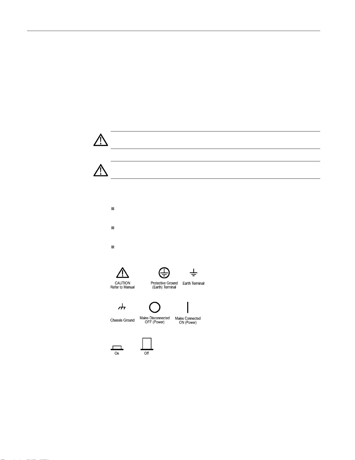
The following symbol(s) may appear on the product:
2 TBS1000 Series Oscilloscopes Installation and Safety Manual

Compliance Information
Compliance In
EMC Compliance
EC Declaration of
Conformity – EMC
formation
This section
environmental standards with which the instrument complies.
Meets intent of Directive 2004/108/EC for Electromagnetic Compatibility.
Compliance was demonstrated to the following specifications as listed in the
Official Journal of the European Communities:
EN 61326-1:2006, EN 61326-2-1:2006. EMC requirements for electrical equipment
for meas
CISPR 11:2003. Radiated and conducted emissions, Group 1, Class A
IEC 61000-4-2:2001. Electrostatic discharge immunity
IEC 61000-4-3:2002. RF electromagnetic field immunity
IEC 61000-4-4:2004. Electrical fast transient/burst immunity
IEC 61000-4-5:2001. Power line surge immunity
lists the EMC (electromagnetic compliance), safety, and
urement, control, and laboratory use.
123
4
1000-4-6:2003. Conducted RF immunity
IEC 6
IEC 61000-4-11:2004. Voltage dips and interruptions immunity
EN 61000-3-2:2006. AC power line harmonic emissions
EN 61000-3-3:1995. Voltage changes, fluctuations, and flicker
5
6
TBS1000 Series Oscilloscopes Installation and Safety Manual 3

Compliance Information
Australia
/ New Zealand
Declaration of
Conformity – EMC
European Conta
ct.
Tektronix UK, Ltd.
Western Peninsula
Western Road
Bracknell, RG12 1RF
United Kingdom
1
This product is intended for use in nonresidential areas only. Use in residential areas may cause electromagnetic
interference.
2
Emissions which exceed the levels required by this standard may occur when this equipment is connected to a
test object.
3
To ensure compliance with the EMC standards listed here, high quality shielded interface cables should be used.
4
The instrument will exhibit ≤ 1.0 division waveform displacement and ≤ 2.0 division increase in peak-to-peak
noise when subjected to radiated interference per IEC 61000-4-3.
5
The instrument will exhibit ≤ 0.5 division waveform displacement and ≤ 1.0 division increase in peak-to-peak
noise when subjected to conducted interference per IEC 61000-4-6.
6
Performance Criterion C applied at the 70%/25 cycle Voltage-Dip and the 0%/250 cycle Voltage-Interruption test
levels (IEC 61000-4-11). If the instrument powers down upon a voltage dip or interruption, it will take longer than
ten seconds to return to the previous operating state.
Complies with the EMC provision of the Radiocommunications Act per the
following standard, in accordance with ACMA:
CISPR 11:2003. Radiated and Conducted Emissions, Group 1, Class A, in
accordance with EN 61326-1:2006 and EN 61326-2-1:2006.
4 TBS1000 Series Oscilloscopes Installation and Safety Manual

Compliance Information
Safety Compli
ance
EC Declaration of
Conformity – Low Voltage
U.S. Natio
nally Recognized
Testing Laboratory Listing
Canadian Certification
Additional Compliances
Equipment Type
Compliance was demonstrated to the following specification as listed in the
Official Journal of the European Communities:
Low Voltage Directive 2006/95/EC.
EN 61010-1: 2001. Safety requirements for electrical equipment for
measurement control and laboratory use.
UL 61010-1:2004, 2ndEdition. Standard for electrical measuring and test
equipment.
CAN/CSA-C22.2 No. 61010-1:2004. Safety requirements for electrical
equipment for measurement, control, and laboratory use. Part 1.
IEC 61010-1: 2001. Safety requirements for electrical equipment for
measurement, control, and laboratory use.
nd measuring equipment.
Test a
Safety Class
Pollution Degree
Description
Class1–groundedproduct.
A measure of the contaminants that could occur in the environment around
and within a product. Typically the internal environment inside a product is
considered to be the same as the external. Products should be used only in the
environment for which they are rated.
Pollution Degree 1. No pollution or only dry, nonconductive pollution occurs.
Products in this category are generally encapsulated, hermetically sealed, or
cated in clean rooms.
lo
Pollution Degree 2. Normally only dry, nonconductive pollution occurs.
ccasionally a temporary conductivity that is caused by condensation must
O
be expected. This location is a typical office/home environment. Temporary
condensation occurs only when the product is out of service.
Pollution Degree 3 . Conductive pollution, or dry, nonconductive pollution
that becomes conductive due to condensation. These are sheltered locations
where neither temperature nor humidity is controlled. The area is protected
from direct sunshine, rain, or direct wind.
Pollution Degree 4. Pollution that generates persistent conductivity through
conductive dust, rain, or snow. Typical outdoor locations.
TBS1000 Series Oscilloscopes Installation and Safety Manual 5
Compliance Information
Installation (Overvoltage)
Category Descriptions
Overvoltage Category
Terminals on th
designations. The installation categories are:
Measurement C
low-voltage installation.
Measuremen
installation.
Measuremen
connected to the low-voltage installation.
Measureme
directly connected to MAINS.
Overvoltage Category II (as defined in IEC 61010-1).
Environmental Considerations
This section provides information about the environmental impact of the product.
Product End-of-Life
Handling
Observ
Equipment Recycling. Production of this equipment required the extraction and
use of natural resources. The equipment may contain substances that could be
harmful to the environment or human health if improperly handled at the product’s
end of life. In order to avoid release of such substances into the environment and
to re
in an appropriate system that will ensure that most of the materials are reused or
recycled appropriately.
e the following guidelines when recycling an instrument or component:
duce the use of natural resources, we encourage you to recycle this product
is product may have different installation (overvoltage) category
ategory IV. For measurements performed at the source of
t Category III. For measurements performed in the building
t Category II. For m easurements performed on circuits directly
nt Category I. For measurements performed on circuits not
This symbol indicates that this product complies with the applicable European
ion requirements according to Directives 2002/96/EC and 2006/66/EC
Un
on waste electrical and electronic equipment (WEEE) and batteries. For
information about recycling options, check the Support/Service section of the
ktronix Web site (www.tektronix.com).
Te
hisproductisclassified as an industrial monitoring and control instrument,
Restriction of Hazardous
Substances
6 TBS1000 Series Oscilloscopes Installation and Safety Manual
T
and is not required to comply with the substance restrictions of the recast RoHS
Directive 2011/65/EU until July 22, 2017.

Getting Started
Getting Start
Installation
Power Cord
ed
TBS1000 Seri
es Digital Storage Oscilloscopes are small, lightweight, benchtop
instruments, which you can use to take ground-referenced measurements.
Model Channels Bandwidth Sample rate Display
TBS1022
TBS1042
TBS1062
TBS1102
TBS1152
225MHz
240MHz
260MHz
2 100 MHz
2 150 MHz
500 MS/s Color
500 MS/s Color
1 GS/s Color
1 GS/s Color
1 GS/s Color
NOTE. You can select a language to display on the screen when you power on the
oscilloscope. At any time, you can also access the Utility ► Language option to
select a language.
nly the power cord provided with your oscilloscope. Appendix B:
Use o
Accessories lists the standard and the optional accessories.
Power Source
Security Loop
Use a power source that delivers 90 to 264 VAC
Hz power source, it must deliver 90 to 132 VAC
400
,45to66Hz. Ifyouhavea
RMS
, 360 to 440 Hz.
RMS
Use a standard laptop computer security lock, or thread a security cable through
the built-in cable channel to secure your oscilloscope to your location.
Security cable channel Security l ock hole
Power cord
TBS1000 Series Oscilloscopes Installation and Safety Manual 7

Getting Started
Ventilation
Functional Check
NOTE. The oscil
loscope cools by convection. Keep two inches clear on the sides
and top of the product to allow adequate air flow.
Perform this functional check to verify that your oscilloscope is operating
correctly.
ON/OFF button
1. Power on the oscilloscope.
Push the Default Setup button.
The default Probe option attenuation setting is
10X.
Default Setup button
PROBE COMP
2. Connect the TPP0101/TP0201 probe to channel
1 on the oscilloscope. To do this, align the slot
in the probe connector with the key on the CH 1
BNC, push to c onnect, and twist to the right to
lock the probe in place.
Connect the probe tip and reference lead to the
PROBE COMP terminals.
3. Push the AutoSet button. Within a few seconds,
you should see a square wave in the display of
about 5V peak-to-peak at 1 kHz.
Push the 1 channel 1 menu button on the front
panel twice to remove channel 1, push the 2
channel 2 menu button to display channel 2, and
repeat steps 2 and 3.
8 TBS1000 Series Oscilloscopes Installation and Safety Manual

Probe Safety
Getting Started
Check and observe probe ratings before using probes.
A guard around the TPP0101/TPP0201 probe body provides a finger barrier for
protection from electric shock.
Finger guard
WARNING. To avoid electric shock when using the probe, keep fingers behind
the guard on the probe body.
To avoid electric shock while using the probe, do not touch metallic portions of
the probe head while it is connected to a voltage source.
Volta
Connect the probe to the oscilloscope, and connect the ground terminal to ground
before you take any measurements.
ge Probe Check Wizard
You can use the Probe Check Wizard to verify that a voltage probe is operating
properly. The wizard does not support current probes.
The wizard helps you adjust the compensation for voltage probes (usually with a
screw on the probe body or probe connector) and set the factor for the Attenuation
ion for each channel, such as in the 1 ► Probe ► Voltage ► Attenuation
opt
option.
TBS1000 Series Oscilloscopes Installation and Safety Manual 9

Getting Started
You should use t
an input channel.
T o use the Prob
probe is connected properly, compensated properly, and the Attenuation option in
the oscilloscope Vertical menu is set to match the probe, the oscilloscope displays
a PASSED message at the bottom of the screen. Otherwise, the oscilloscope
displays directions on the screen to guide you in correcting these problems.
NOTE. The Probe Check Wizard is useful for 1X, 10X, 20X, 50X, and 100X
probes. It
the Ext Trig BNC.
NOTE. Wh
oscilloscope settings (other than the Probe option) to what they were before you
pushed the PROBE CHECK button.
To co m p
steps:
1. Conne
ensate a probe that you plan to use with the Ext Trig input, follow these
he Probe Check Wizard each time you connect a voltage probe to
e Check Wizard, push the PROBE CHECK button. If the voltage
is not useful for 500X or 1000X probes, or for probes connected to
en the process is complete, the Probe Check Wizard restores the
ct the probe to any input channel BNC, such as to channel 1.
2. Push the PROBE CHECK button and follow the directions on the screen.
3. After you verify that the probe functions and is compensated properly, connect
the probe to the Ext Trig BNC.
10 TBS1000 Series Oscilloscopes Installation and Safety Manual

Getting Started
Manual Probe C
ompensation
As an alternative method to the Probe Check Wizard, you can manually perform
this adjustment to match your probe to the input channel.
PROBE COMP AutoSet
button
1. Push the 1 ► Probe ► Voltag e ►
Attenuation option and select 10X. Connect
the TPP0101/TPP0201 probe to channel 1 on
the oscilloscope. If you use the probe hook-tip,
ensure a proper connection by firmly inserting the
tip onto the probe.
2. AttachtheprobetiptothePROBECOMP
~5V@1kHz terminal and the reference lead to
the PROBE COMP chassis terminal. Display the
channel, and then push the AutoSet button.
3. Check the shape of the displayed waveform.
Overcompensated
Undercompensated
e Attenuation Setting
Prob
Compensated correctly
4. If necessary, adjust your probe.
Repeat as necessary.
Probes are available with various attenuation factors which affect the vertical
scale of the signal. The Probe Check Wizard verifies that the attenuation factor
the oscilloscope matches the probe.
in
As an alternative method to Probe Check, you can manually select the factor
at matches the attenuation of your probe. For example, to match a probe set
th
to10XconnectedtoCH1,pushthe1 ► Probe ► Volt age ► Attenuation
option, and select 10X.
NOTE. The default setting for the Attenuation option is 10X.
TBS1000 Series Oscilloscopes Installation and Safety Manual 11

Getting Started
Current P
robe Scaling
If you change th
the oscilloscope Attenuation option to match. Switch settings are 1X and 10X.
NOTE. When the Attenuation switch is set to 1X, the P2220 probe limits the
bandwidth of the oscilloscope to 6 MHz. To use the full bandwidth of the
oscilloscope, be sure to set the switch to 10X.
Current probes provide a voltage signal proportional to the current. You need to
set the oscilloscope to match the scale of your current probe. The default scale is
10 A/V.
For example, to set the scale for a current probe connected to CH 1, push the 1 ►
Probe ►
e Attenuation switch on a P2220 probe, you also need to change
Attenuation switch
Current ► Scale option, and select an appropriate value.
Self Calibration
elf calibration routine lets you optimize the oscilloscope signal path for
The s
maximum measurement accuracy. You can run the routine at any time but you
should always run the routine if the ambient temperature changes by 5 °C (9 °F)
or more. The routine takes about two minutes.
For accurate calibration, power on the oscilloscope and wait twenty minutes to
ensure it is warmed up.
To compensate the signal path, disconnect any probes or cables from the input
connectors. Then, access the Utility ► Do Self Cal option, and follow the
directions on the screen.
12 TBS1000 Series Oscilloscopes Installation and Safety Manual

Firmware Updates Through the Internet
If a newer version of firmware becomes available, you can use the Internet and
aUSBflash drive to update your oscilloscope. If you do not have access to the
Internet, contact Tektronix for information on update procedures.
To update the firmware from the Internet, follow these steps:
1. Push the Utility ► System Status option, and write down the firmware
version number of the oscilloscope.
2. From your computer, access the www.tektronix.com web site and check if a
newer version of oscilloscope firmware is available.
3. Ifthereisanewerversionoffirmware, download the firmware file from the
web page.
You may need to unzip the downloaded file.
4. Copy the firmware file to the root folder of a USB flash drive.
Getting Started
5. Insert
6. From y
It ta
Your oscilloscope will prompt you to press a button when the firmware update is
com
until the firmware update is complete.
the USB flash drive into the USB Flash Drive port on the front of the
oscilloscope.
our oscilloscope, push the Utility ► File Utilities ► -more-page2
of 2 ► Update Firmware option button.
kes several minutes to update the firmware.
plete. You must not remove the USB flash drive, or power off the oscilloscope
TBS1000 Series Oscilloscopes Installation and Safety Manual 13

Operating Basics
Operating Bas
ics
The front pan
you with a quick overview of the controls and the information displayed on the
screen.
el is divided into easy-to-use functional areas. This chapter provides
14 TBS1000 Series Oscilloscopes Installation and Safety Manual

Display Area
Operating Basics
In addition to displaying waveforms, the display is filled with many details about
the waveform and the oscilloscope control settings.
TBS1000 Series Oscilloscopes Installation and Safety Manual 15

Operating Basics
1. Icon display sh
ows acquisition mode.
Sample mode
Peak detect mode
Average mode
2. Trigger status indicates the following:
The oscilloscope is acquiring pretrigger data. All triggers are
ignored in this state.
All pretrigger data has been acquired and the oscilloscope is
ready to accept a trigger.
The oscilloscope has seen a trigger and is acquiring the
posttrigger data.
The oscilloscope has stopped acquiring waveform data.
The oscilloscope has completed a Single Sequence acquisition.
The oscilloscope is in auto mode and is acquiring waveforms in
the absence of triggers.
The oscilloscope is acquiring and displaying waveform data
continuously in scan mode.
3. Marker shows horizontal trigger position. Turn the Horizontal Position knob
to adjust the position of the marker.
4. Readout shows the t
ime at the center graticule. The trigger time is zero.
5. Marker shows Edge or Pulse Width trigger level.
6. On-screen markers show the ground reference points of the displayed
waveforms. If there is no marker, the channel is not displayed.
7. An arrow icon indicates that the waveform is inverted.
8. Readouts show the vertical scale factors of the channels.
9. AB
icon indicates t
W
hat the channel is bandwidth limited.
10. Readout shows main time base setting.
11. Readout shows window time base setting if it is in use.
12. Readout shows trigger source used for triggering.
13. Icon shows selected trigger type as follows:
Edge trigger for the rising edge.
Edge trigger for the falling edge.
16 TBS1000 Series Oscilloscopes Installation and Safety Manual

Video trigger for line sync.
Video trigger for field sync.
Pulse Width t
rigger, positive polarity.
Operating Basics
Message Area
Pulse Width
trigger, negative polarity.
14. Readout shows Edge or Pulse Width trigger level.
15. Display area shows helpful messages; some messages display for only three
seconds.
If you recall a saved waveform, readout shows information about the reference
waveform, such as RefA 1.00V 500µs.
16. Readout shows date and time.
17. Readout shows trigger frequency.
The oscilloscope displays a message area (item number 15 in the previous figure)
bottom of the screen that conveys the following types of helpful information:
at the
Directions to access another menu, such as when you push the Tri g Me n u
on:
butt
For TRIGGER HOLDOFF, go to HORIZONTAL MENU
Suggestion of what you might want to do next, such as when you push the
Measure button:
Using the Menu System
Push an option button to change its measurement
Information about the action the oscilloscope performed, such as when you
push the Default Setup button:
Default setup recalled
Information about the waveform, such as when you push the AutoSet button:
Square wave or pulse detected on CH1
The user interface of the oscilloscopes was designed for easy access to specialized
functions through the menu structure.
When you push a front-panel button, the oscilloscope displays the corresponding
menu on the right side of the screen. The menu shows the options that are available
when you push the unlabeled option buttons directly to the right of the screen.
TBS1000 Series Oscilloscopes Installation and Safety Manual 17

Operating Basics
The oscillosco
pe uses several m ethods to display menu options:
Page (Submenu) Selection: For some menus, y ou can use the top option
buttontochoo
se two or three submenus. Each time you push the top button,
the options change. For example, when you push the top button in the Trigger
Menu, the oscilloscope cycles through the Edge, Video, and Pulse Width
trigger submenus.
Circular List: The oscilloscope sets the parameter to a different value each
time you push the option button. For example, you can push the 1 (channel
1 menu) button and then push the top option button to cycle through the
Vertical (channel) Coupling options.
In some lists, you can use the multipurpose knob to select an option. A hint
line tells you when the multipurpose knob can be used, and an LED by the
multipu
rpose knob lights when the knob is active. (See page 21, Menu and
Control Buttons.)
Action
: The oscilloscope displays the type of action that will immediately
occur when you push an Action option button. For example, when the Help
Index is visible, and you push the Page Down option button, the oscilloscope
immediately displays the next page of index entries.
Radio: The oscilloscope uses a different button for each option. The
currently-selected option is highlighted. For example, the o scilloscope
displays various acquisition mode options when you push the Acquire Menu
button. To select an option, push the corresponding button.
Page Sele ction Circular List
TRIGGER CH1
Type
Edge
or or
TRIGGER CH1
Type
Video
or or
TRIGGER CH1
Type
Pulse
Coupling
DC
Coupling
AC
Coupling
Ground
Action Radio
HELP
Page
Up
Page
Down
ACQUIRE
Sample
ak Detect
Pe
Average
18 TBS1000 Series Oscilloscopes Installation and Safety Manual

Operating Basics
Vertical Cont
rols
Vertical Measurement Overrange (Clipping). A display of ? in the measurement
readout indicates an invalid value. This may be due to waveforms that extend
beyond the screen (overrange). Adjust the vertical scaling to ensure the readout
is valid.
Positio
1&2Menu. Displays the Vertical menu selections and toggles the display of the
channel waveform on and off.
n(1&2). Positions a waveform vertically.
Horizontal Controls
Scale (1 & 2). Selects vertical scale factors.
Math. Displays waveform math operations menu and toggles the display of the
math waveform on and off.
TBS1000 Series Oscilloscopes Installation and Safety Manual 19

Operating Basics
Trigger Controls
Position. Adju
resolution of this control varies with the time base setting.
NOTE. To make a large adjustment to the horizontal position, turn the Horizontal
Scale knob to a larger value, change the horizontal position, and then turn the
Horizontal Scale knob back to the previous value.
Horiz. Displays the Horizontal Menu.
Set to Zero. Sets the horizontal position to zero.
Scale. Se
window time base. When Window Zone is enabled, it changes the width of the
window zone by changing the window time base.
sts the horizontal position of all channel and math waveforms. The
lects the horizontal time/division (scale factor) for the main or the
Level. When you use an Edge or Pulse trigger, the Level knob sets the amplitude
level that the signal must cross to acquire a waveform.
Trig Menu. Displays the Trigger Menu.
tTo50%. The trigger level is set to the vertical midpoint between the peaks of
Se
the trigger signal.
Force Trig. Completes an acquisition regardless of an adequate trigger signal.
This button has no effect if the acquisition is already stopped.
Trig View. Displays the trigger waveform in place of the channel waveform while
you hold down the Trig View button. Use this to see how the trigger settings
affect the trigger signal, such as trigger coupling.
20 TBS1000 Series Oscilloscopes Installation and Safety Manual

Operating Basics
Menu and Contr
ol Buttons
Multipurpose knob
Refer to the Reference chapter for detailed information on the menu and button
controls.
Multipurpose Knob. Thefunctionisdeterminedbythedisplayedmenuorselected
menu option. When active, the adjacent LED lights. The next table lists the
functio
Active menu or option Knob function Description
Cursor Cursor 1 or Cursor 2
Help
Horiz
Math
Measure Type
Save/Recall
Trigger
ontal
ns.
Positions the selected cursor
Scroll Selects entries in the Index; selects
in a topic; displays the next or
links
previous page for a topic
Holdoff Sets the amount of time before another
trigger event can be accepted;
Position
Vertical Scale Changes the scale of the Math
tion
Ac
File selection
Source Selects the source when the Trigger
Video line number
Pulse width
Positions the Math waveform
eform
wav
ects the type of automatic
Sel
measurement for each source
Sets the transaction as save or recall
for setup files, waveform files, and
reen images
sc
elects setup, waveform, or image files
S
to save, or selects setup or w aveform
files to recall
Type option is set to Edge
Sets the oscilloscope to a specificline
number when the Trigger Type option
is set to Video and the Sync option is
set to Line Number
Sets the width of the pulse when the
Trigger Type option is set to Pulse
TBS1000 Series Oscilloscopes Installation and Safety Manual 21

Operating Basics
Active m enu or option Knob function Description
Utility ► File
Utility ► Options ►
GPIB Setup ► Address
Utility ► Options ► Set
Date and Tim
Vertical ► Probe ►
Voltage ► A
Vertical ► Probe ►
Current ► Scale
Utilities
e
ttenuation
File selectio
Name entry
Value entry
Value entry
Value entry
Value entry
n
Selects files to rename or delete;
Renames the file or folder;
Sets the GPIB address for the
TEK-USB-488 adapter
Sets the value for the date and time;
For a chann
1 menu), sets the attenuation factor in
the oscilloscope
For a of channel menu (such as the
CH 1 menu)
oscilloscope
el menu (such as the CH
, sets the scale in the
AutoRange. Displays the Autorange Menu, and activates or deactivates the
autoranging function. When autoranging is active, the adjacent LED lights.
Save/Recall. Displays the Save/Recall Menu for setups and waveforms.
Measure. Displays the automated measurements menu.
Acquire. Displays the Acquire Menu.
Ref. Displays the Reference Menu to quickly display and hide reference
waveforms stored in the oscilloscope non-volatile memory.
Utility. Displays the Utility Menu.
Cursor. Displays the Cursor Menu. Cursors remain visible (unless the Type
option is set to Off) after you leave the Cursor Menu but are not adjustable.
Display. Displays the Display Menu.
Help. Displays the Help Menu.
Default Setup. Recalls the factory setup.
AutoSet. Automatically sets the oscilloscope controls to produce a usable display
of the input signals.
Single. (Single sequence) Acquires a single waveform and then stops.
Run/Stop. Continuously acquires waveforms or stops the acquisition.
Starts the print operation to a PictBridge compatible printer, or performs the
SavefunctiontotheUSBflash drive.
Save. An LED indicates when the print button is configuredtosavedatatothe
USB flash drive.
22 TBS1000 Series Oscilloscopes Installation and Safety Manual
Operating Basics
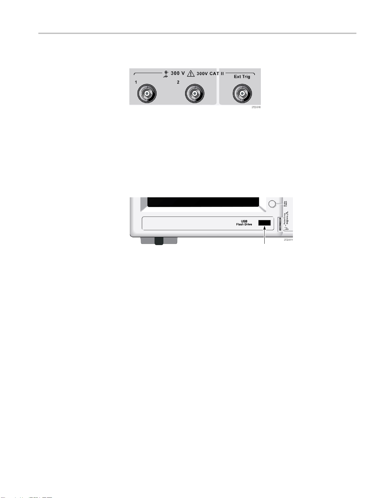
Input Connect
ors
Other Front-Panel Items
1&2. Input connectors for waveform display.
Ext Trig. Input connector for an external trigger source. Use the Trigger Menu to
select the
how the trigger settings affect the trigger signal, such as trigger coupling.
Ext, or Ext/5 trigger source. Push and hold the Trig Vi e w button to see
USB Flash Drive port
USB Flash Drive Port. Insert a USB flash drive for data storage or retrieval. The
oscilloscope displays a clock symbol to indicate when the flash drive is active.
After a file is saved or retrieved, the oscilloscope removes the clock, and displays
a hint line to notify you that the save or recall operation is complete.
For flash drives with an LED, the LED blinks when saving data to or retrieving
data from the drive. Wait until the LED stops to remove the drive.
PROBE COMP. Probe compensation output and chassis refe rence. Use to
electrically match a voltage probe to the oscilloscope input circuit.(See page 11,
Manual Probe Compensation.)
TBS1000 Series Oscilloscopes Installation and Safety Manual 23

Operating Basics
Installing th
e PC Communications Software on a PC
Before you connect the oscilloscope to a PC with Tektronix OpenChoice
PC Communications Software, download that software from
www.tektron
CAUTION. If you connect the oscilloscope to your PC before you install the
software, the PC will not recognize the oscilloscope. The PC will label the
oscilloscope as an Unknown Device and not communicate with the oscilloscope.
To avoid this, install the software on your PC before you connect the oscilloscope
to your PC.
NOTE. Be sure you have installed the latest version of PC Communications
software.
Software for your oscilloscope is available through the Software finder on the
Tektronix web site.
To install the PC Communications software, follow these steps:
1. Run the OpenChoice Desktop software on the PC. The InstallShield wizard
appears on the screen.
ix.com/software and install it on your PC.
Connecting to a PC
2. Follow the on-screen directions.
3. Exit the InstallShield wizard.
After you install the software on your PC, you can connect the oscilloscope to
the PC.
(See page 24, Installing the PC Communications Software on a PC.)
NOTE. You must install the s oftware before you connect the oscilloscope to the
PC. (See page 24, Installing the PC Communications Software on a PC.)
To connect the o scilloscope to the PC, follow these steps:
1. Power on the oscilloscope.
2. Insert one end of a USB cable into the USB Device port on the back of the
oscilloscope.
3. Power on the PC.
4. Insert the other end of the cable into the desired USB port on a PC.
24 TBS1000 Series Oscilloscopes Installation and Safety Manual

Operating Basics
5. If a Found New Ha
for the Found New Hardware wizard.
Do NOT search f
6. For a Windows XP systems, follow these steps:
a. If you see the Tektronix PictBridge Device dialog box, click Cancel.
b. When prompted, select the option that tells Windows NOT to connect to
Windows Update, and click Next.
c. In the next window, you should see that you are installing software for
a USB Test and Measurement Device. If you do not see USB Test and
Measurement Device software, the OpenChoice Desktop software is not
properly
d. Select the option that installs the software automatically (the
recomme
Windows will install the driver for your oscilloscope.
e. If you do not see the USB Test and Measurement Device in step c, or
if Windows cannot find the software driver, the OpenChoice Desktop
are is not properly installed.
softw
In these situations, click Cancel to exit the Found New Hardware wizard.
Do NO
T allow the wizard to finish.
rdware message appears, follow the on-screen directions
or the hardware to install on the web.
installed.
nded option) and click Next.
Unplug the USB cable from your oscilloscope and install the OpenChoice
ktop software.
Des
Reconnect your oscilloscope to the PC and follow steps 6a, 6b, 6c, and 6d.
f. Click Finish.
g. If a dialog labeled Test and Measurement Device appears, select what you
would like Windows to do, and click OK.
TBS1000 Series Oscilloscopes Installation and Safety Manual 25

Operating Basics
7. For Windows 200
a. When prompted, select the option that tells Windows to display a list
of known drive
b. In the next window, select USB Test and Measurement Device. If you do
not see a USB
Desktop software is not properly installed.
c. In the next w
for your oscilloscope.
Windows wi
d. If you do not see the USB Test and Measurement Device in step b, or if
Windows c
installed.
In these
Do NOT allow the wizard to finish.
Unplug
Reconnect your oscilloscope to the PC and follow steps 7a, 7b, and 7c.
8. When prompted, click Finish.
0systems:
rs and click Next.
Test and Measurement Device selection, the OpenChoice
indow, click Next to allow Windows to install the driver
ll install the driver for your oscilloscope.
annot find the software driver, the software is not properly
situations, click Cancel to exi t the Found New Hardware wizard.
the USB cable from your oscilloscope, and install the software.
9. If Windows asks you to insert a CD, click Cancel.
10. Run the PC Communications software on your PC.
11. If the oscilloscope and PC do not communicate, refer to the PC
Communications online h elp and documentation.
26 TBS1000 Series Oscilloscopes Installation and Safety Manual

Specifications
Specification
s
All specifica
probe specifications appear in Appendix B. To verify that the oscilloscope meets
specifications, the oscilloscope must first meet the following conditions:
The oscilloscope must have been operating continuously for twenty minutes
within the specified operating temperature.
You must perform the Do Self Cal operation, accessible through the Utility
menu, if the operating temperature changes by more than 5 °C (9 °F ).
The oscilloscope must be within the factory calibration interval.
All spec
Oscilloscope Specifications
Table 1
Characteristic Description
Maximum Input Voltage
: Input Specifications
At front panel connector, 300 V RMS, Installation Category II; derate at 20 dB/decade above 100 kHz to 13 V peak AC at 3 MHz and
above.
Based upon sinusoidal or DC input signal. Maximum viewable signal while DC coupled is ±50 V offset ±5 V/division at 4 divisions, or
70 V. AC coupling allows measuring signals on a DC level up to 300 V. For non-sinusoidal waveforms, peak value must be less than
450 V. Excursion above 300 V should be less than 100 ms duration and the duty factor is limited to < 44%. RMS signal level must be
limited to 300 V. If these values are exceeded, damage to the instrument may result.
tions apply to the TBS1000 series models. TPP0101 and TPP0201
ifications are guaranteed unless noted “typical.”
Table 2: General Specifications
Characteristic
Probe Compensator Output
Probe Compensator, Output
Voltage and Frequency, typical
Power Source
Source Voltage Full Range: 100 to 240 VAC RMS ±10%, Installation Category II (Covers range of 90 to 264 VAC); 50/60 Hz.
Power Consumption Less than 30 W at 90 to 264 VAC input.
Environmental
Temperature
Cooling Method Convection cooled
Description
Characteristics are as follows:
Output voltage 5.0 V ±10% into 1 Meg Ω load
Frequency 1 kHz
115 VAC RMS ±10%; 400 Hz.
Operating 0° C to +50° C, with 5° C/minute
Nonoperating
maximum gradient, non-condensing,
up to 3000m altitude
-40° C to +71° C, with 5° C/minute
maximum gradient
TBS1000 Series Oscilloscopes Installation and Safety Manual 27

Specifications
Table 2: General Specifications, (cont.)
Characteris
Humidity: Operating and
Non-Operat
Altitude
Non-Operating
tic
ing
: Operating and
Mechanical
Overall Dimensions
Weight
Description
Operating: 5% to 85% relative humidity (% RH) at up to +40° C
5% to 45% RH a
Maximum Wet-Bulb Temperature of +37° C (derates relative humidity to 45 % RH at
+50° C)
Non-Operating: 5% to 85% RH (Relative Humidity) at up to +40° C,
5% to 45% RH above +40° C up to +50° C, non-condensing.
Above +50°
relative humidity to 12% RH at +71° C)
g:
Operatin
Non-Operating: Up to 3000 meters (10,000 feet).
Requirements that follow are nominal:
Height
Width
Depth
rements that follow are nominal:
Requi
Stand alone instrument 2.0 kg (4.4 lbs)
accessories
With
packaged for domestic shipment
When
Up to 3000
e is limited by possible damage to LCD at higher altitudes. This damage is
Altitud
independent of operation
bove +40° C up to +50° C, non-condensing, and as limited by a
C limited by a Maximum Wet-Bulb Temperature of +37° C (derates
meters (10,000 feet)
m (6.22 in.)
158.0 m
326.3 mm (12.85 in)
124.1 mm (4.88 in)
2.2 kg (4.9 lbs)
g(8lbs)
3.6 k
28 TBS1000 Series Oscilloscopes Installation and Safety Manual

TPP0101 and TPP0201 Series 10X Passive Probes Information
TPP0101 and TP
P0201 Series 10X Passive Probes
Information
The TPP0101 & TPP0201 Series 10X Passive Probes are high impedance,
passive probes with 10X attenuation. They are designed for use with TBS1000
oscillosco
The compensation range of these probes is 15–25 pF.
The probes have no user- or Tektronix-serviceable parts.
WARNING. Do not float the TPP0101 and TPP0201 probes on any oscilloscope.
Connecting the Probe to the Oscilloscope
Connect the p robe as shown in the illustrations below.
pes. These oscilloscopes have 20 pF of input capacitance.
Compensating the Probe
Due to variations in oscilloscope input characteristics, the low-frequency
compensation of the probe may need adjustment after moving the probe from
one oscilloscope channel to another.
If a 1 kHz calibrated square wave displayed at 1 ms/division shows significant
differences between the leading and trailing edges, perform the following steps to
optimiz
TBS1000 Series Oscilloscopes Installation and Safety Manual 29
e low-frequency compensation:

TPP0101 and TPP0201 Series 10X Passive Probes Information
1. Connect the pro
measurements.
2. Connect the pr
oscilloscope front panel.
WARNING. To avoid electric shock, only connect to the Probe Comp signal on the
oscilloscope when making this adjustment.
3. Push Autoset or otherwise adjust your oscilloscope to display a stable
waveform.
4. Adjust the trimmer in the probe until you see a perfectly flat-top square wave
on the display. (See illustration.)
WARNING. To avoid electric shock, only use the insulated adjustment tool when
making compensation adjustments.
be to the oscilloscope channel that you plan to use for your
obe to the probe compensation output terminals on the
Connecting the Probe to the Circuit
Use the standard accessories included with the probe to connect to your circuit.
WARNING. To avoid electric shock when using the probe or accessories, keep
fingers behind the finger guard of the probe body and accessories.
educe risk of shock, ensure the ground lead and ground spring are fully mated
To r
before connecting the probe to the circuit under test.
30 TBS1000 Series Oscilloscopes Installation and Safety Manual
TPP0101 and TPP0201 Series 10X Passive Probes Information
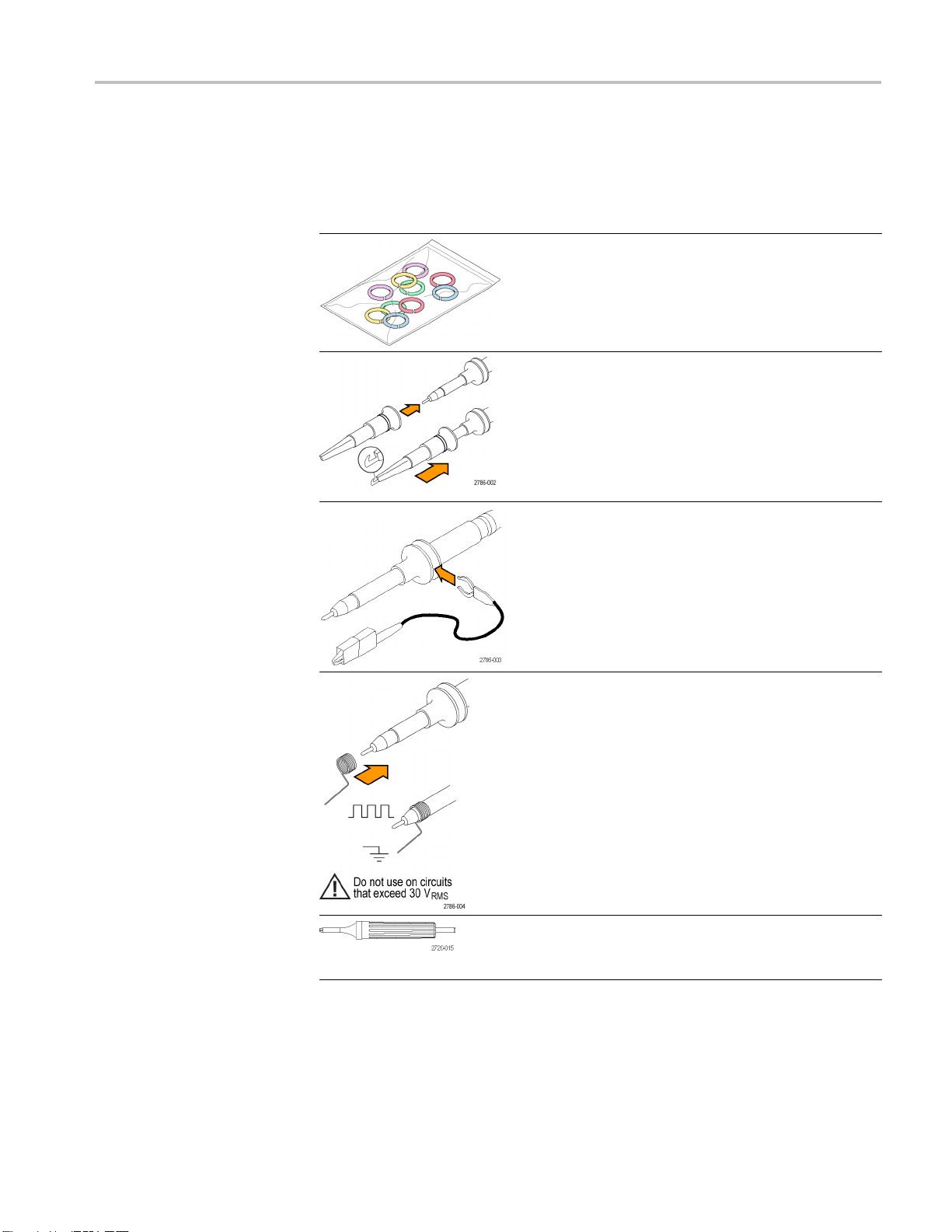
Standard Acce
ssories
The accessories included with the probe are shown below.
Item Description
Color bands
Use these bands to identify the
oscilloscope channel at the probe head.
Reorder Tek
016-0633-xx (5 pairs)
Hook tip
Press the hook tip onto probe tip and
then clamp the hook onto the circuit.
Reorder Tektronix part number
013-0362
Ground l
Secure the lead to the probe head
ground and then to your circuit ground.
-xx
ead, with alligator clip
tronix part number
Reorder Tektronix part number
21- xx
196-35
Ground spring
The ground spring minimizes
ations on high-frequency signals
aberr
caused by the inductance of the ground
path, giving you measurements with
signal fidelity.
good
Attach the spring to the ground band on
the probe tip. You can bend the spring
o ~0.75 in. away from the signal
out t
test point.
Reorder Tektronix part number
-2028-xx (2 ea.)
016
Adjustment tool
Reorder Tektronix part number
-1433-xx
003
TBS1000 Series Oscilloscopes Installation and Safety Manual 31

TPP0101 and TPP0201 Series 10X Passive Probes Information
Optional Acce
Specifications
ssories
You can order the following accessories for your probe.
Accessory Part number
Alligator Ground Lead, 12 in
6” Clip-on Ground Lead
Ground Spring, Short, 2 ea.
MicroCKT Test Tip
Micro Hook Tip 013-0363-xx
Universal IC Cap
Circuit Board Test Point/PCB Adapter
Wire, spool, 32 AWG
196-3512-xx
196-3198-xx
016-2034-xx
206-0569-xx
013-0366-xx
016-2016-xx
020-3045-xx
Table 3: Electrical and mechanical specifications
Characteristic TPP0101 TPP0201
Bandwidth (–3 dB) DC to 100 MHz DC to 200 MHz
System attenuation accuracy 10:1 ±3.2% 10:1 ±3.2%
Compensation range
System input resistance
@DC
System input capacitance
System rise time (typical)
Propagation delay ~6.1 ns ~6.1 ns
Maximum input voltage
Cable length
TPP0101:
15 pF – 25 pF
10 MΩ ±1.5% 10 MΩ ±1.5%
<12 pF <12 pF
<3.5 ns <2.3 ns
300 V
1.3 m 1.3 m
CAT II 300 V
RMS
TPP0201:
15 pF – 25 pF
CAT II
RMS
Table 4: Environmental specifications
Characteristics Description
Temperature
Operating
Nonoperating
Humidity
Operating and
Non-Operating
Altitude
Operating
Nonoperating
–10 °C to +55 °C (14 °F to +131 °F)
–51 °C to +71 °C (–60 °F to +160 °F)
5% to 95% relative humidity (%RH) up to +30 °C (86 °F), 5% to
65% RH above +30° C up to +55 °C (131 °F)
3.0 km (10,000 ft) maximum
12.2 km (40,000 ft) maximum
32 TBS1000 Series Oscilloscopes Installation and Safety Manual

TPP0101 and TPP0201 Series 10X Passive Probes Information
Performance G
raphs
Table 5: Cer tifications and compliances
Characteristics Description
EC Declaration of
Conformity
Safety Standards
Compliance was demonstrated to the following specification as listed
in the Official Journal of the European Communities:
Low Voltage Directive 2006/95/EC:
EN61010-031: 2002
UL61010-031;2007
CAN/CSA C22.2 No. 61010-031-07
IEC61010-031; IEC 61010-031/A1:2008
TBS1000 Series Oscilloscopes Installation and Safety Manual 33

TPP0101 and TPP0201 Series 10X Passive Probes Information
Table 5: Certifications and compliances, (cont.)
Characteristics Description
ty Summary
Safe
Measurement
Category
Descriptions
Pollution Degree 2 Do not operate in environments where cond–
Equipment Recycling. This product complies with the European Union’s
requirements according to Directive 2002/96/EC on waste electrical and
elec
check the Support/Service section of the Tektronix Web site (www.tektronix.com).
Category Examples of Products in this Category
CAT III Distribution-level mains, fixed installation
CAT II
CAT I Circuits not directly connected to m ains.
uctive pollutants may be present (as defined in IEC 61010-1). Rated
for indoor use only.
tronic equipment (WEEE). For more information about recycling options,
Local-level mains, appliances, portable equipment
To Avoid Fire or Personal
jury
In
Review the following safety precautions to avoid injury and prevent damage to
this product or any products connected to it. To avoid potential hazards, use this
oduct only as specified. Using the probe or accessories in a manner not specified
pr
couldresultinashockorfire hazard.
Ground-Referenced Oscilloscope Use. Do not float the reference lead of this
probe when using with ground referenced oscilloscopes (for example, TBS series
oscilloscopes). The reference lead must be connected to earth potential (0 V).
Connect and Disconnect Properly. Connect the probe output to the measurement
instrument before connecting the probe to the circuit under test. Disconnect
the probe input and the probe reference lead from the circuit under t
est before
disconnecting the probe from the measurement instrument.
Avoid Electric Shock. Do not connect or disconnect probes or test leads while
they are connected to a voltage source.
Observe All Terminal Ratings. To a voi d fire or shock hazard, observe all ratings
and markings on the product. Consult the product manual for further ratings
information before making connections to the product.
Avoid Electric Shock. When using probe accessories, never exceed the lowest
rating of the probe or its accessory, whichever is less, including the measurement
category and voltage rating.
Inspect the Probe and Accessories. Before each use, inspect the probe and
accessories for damage (cuts, tears, defects in the probe body, accessories, cable
jacket, etc.). Do not use if damaged.
34 TBS1000 Series Oscilloscopes Installation and Safety Manual
TPP0101 and TPP0201 Series 10X Passive Probes Information
Safety Terms and Symbols
Terms in This Manual.
Do Not Operate i
Do Not Operate in an Explosive Atmosphere.
Keep Product Surfaces Clean and Dry.
These terms
WARNING. Warning statements identify conditions or practices that could result
in injury or loss of life.
CAUTION. Caution statements identify conditions or practices that could result in
damage to this product or other property.
Symbols on the Product. These symbols may appear on the product:
n Wet/Damp Conditions.
may appear in this manual:
TBS1000 Series Oscilloscopes Installation and Safety Manual 35

Accessories
Accessories
Standard Accessories
All accessories (standard and optional) are available by contacting your local
Tektronix field office.
TPP0101 or TPP0201, 10X Passive Voltage Probe. The T PP0101 probes have
a system bandwidth of DC to 100 MHz at -3 dB and ship standard with TBS1000
oscilloscope models that have bandwidths up to 100 MHz.
The TPP0201 probes have a system bandwidth of DC to 200 MHz at -3 dB and ship
standard with T BS1000 oscilloscopes models that have bandwidths of greater than
100 MHz.
TBS1000 Series Oscilloscope Installation and Safety Manual. A single printed
manual is included (071-3099-XX). Refer to the Optional Accessories for a list of
electronically available manuals.
Optional Accessories
Customer
information (063-4479-XX).
P6101B 1X Passive Voltage Probe. The P6101B probe has a 15 MHz bandwidth
witharatingof300V
RM2000B Rackmount Kit. The RM2000B Rackmount Kit lets you install a
TBS1000 series oscilloscope into an industry-standard 19 inch rack. The rackmount kit
requires seven inches (18 cm) of vertical rack space. You can turn the oscilloscope
power on or off from the front of the rackmount kit. The rackmount kit does not have
slide-out capability.
Documentation Browser CD-ROM. This CD offers additional product
CAT II.
RMS
36 TBS1000 Series Oscilloscopes Installation and Safety Manual

Accessories
TBS1000, TDS2000C and TPS2000 Series Digital Oscilloscopes Programmer
Manual . The programmer manual (077-0444-XX, English) provides command and
syntax inform
TBS1000 Series Digital Storage Oscilloscope Service Manual. The service manual
(077-0772-XX, English) provides module-level repair information.
ation.
TBS1000 Seri
available in these languages:
English, 077-0760-XX
French, 077
Italian, 077-0762-XX
German, 077-0763-XX
Spanish, 0
Japanese, 077-0765-XX
Portuguese, 077-0766-XX
Simplifie
Traditional Chinese, 077-0768-XX
Korean, 077-0769-XX
Russian,
Interna
oscilloscope, you can obtain the following cords:
Option A0, North American 120 V, 60 Hz, 161-0066-00
Option
Option A2, United Kingdom 230 V, 50 Hz, 161-0066-10
Option A3, Australian 240 V, 50 Hz, 161-0066-13
Option
Option A6, Japan 100 V, 50/60 Hz, 161–0342–00
Option A10, China 220 V, 50 Hz, 161-0304-00
n A11, India 230 V, 50 Hz, 161-0400-00
Optio
Option A12, Brazil 127/220 V, 60 Hz, 161-0357-00
TEK-USB-488 Adapter. The GPIB adapter allows you to connect your oscilloscope to
a GPIB controller.
es Digital Storage Oscilloscope User Manu als. The user manual is
-0761-XX
7X-0764-XX
d Chinese, 077-0767-XX
077-0770-XX
tional Power Cords. In addition to the power cord shipped with your
A1, European 230 V, 50 Hz, 161-0066-09
A5, Switzerland 230 V, 50 Hz, 161-0154-00
Soft Case. The soft case (AC2100) protects the oscilloscope from damage and
provides space for probes, a power cord, and manuals.
Transit Case. The transit case (HCTEK4321) provides shock, vibration, impact and
moisture protection for the oscilloscope when you transport it from one place to
another. The required soft case fits inside the transit case.
TBS1000 Series Oscilloscopes Installation and Safety Manual 37

Cleaning
Cleaning
General Care
Cleaning
Do not store
direct sunlight for long periods of time.
CAUTION. To avoid damage to the oscilloscope or probes, do not expose them
to sprays, liquids, or solvents.
Inspect the oscilloscope and probes as often as operating conditions require. To
clean th
1. Remove loose dust on the outside of the oscilloscope and probes with a
lint-f
2. Use a soft cloth dampened with water to clean the oscilloscope. Use an
aqueo
CAUTION. To avoid damage to the surface of the oscilloscope or probes, do not
use any abrasive or chemical cleaning agents.
or leave the oscilloscope where the LCD display will be exposed to
e exterior surface, perform the following steps:
ree cloth. Use care to avoid scratching the clear glass display filter.
us solution of 75% isopropyl alcohol for more efficient cleaning.
38 TBS1000 Series Oscilloscopes Installation and Safety Manual

Font Licenses
Font Licenses
The following license agreements cover Asian fonts used in the TBS1000 series
oscilloscopes.
Copyright © 1988 The Institute of Software, Academia Sinica.
Correspondence Address: P.O.Box 8718, Beijing, China 100080.
Permission to use, copy, modify, and distribute this software and its documentation
for any purpose and without fee is hereby granted, provided that the above
copyright notices appear in all copies and that both those copyright notices and
this permission notice appear in supporting documentation, and that the name
of "the In
publicity pertaining to distribution of the software without specific, written prior
permission. The Institute of Software, Academia Sinica, makes no representations
about the suitability of this software for any purpose. It is provided "as is" without
express or implied warranty.
THE INSTITUTE OF SOFTWARE, ACADEMIA SINICA, DISCLAIMS ALL
WARRANTIES WITH REGARD TO TH I S SOFTWARE, INCLUDING ALL
IMPLIED WARRANTIES OF MERCHANTABILITY AND FITNESS, IN NO
EVENT
BE LIABLE FOR ANY SPECIAL, INDIRECT OR CONSEQUENTIAL
DAMAGES OR ANY DAMAGES WHATSOEVER RESULTING FROM LOSS
OF USE, DATA OR PROFITS, WHETHER IN AN ACTION OF CONTRACT,
NEGLIGENCE OR OTHER TORTIOUS ACTION, ARISING OUT OF OR IN
CONNECTION WITH THE USE OR PERFORMANCE OF THIS SOFTWARE.
stitute of Software, Academia Sinica" not be used in advertising or
SHALL THE INSTITUTE OF SOFTWARE, ACADEMIA SINICA,
© Copyright 1986-2000, Hwan Design Inc.
You are hereby granted permission under all Hwan Design propriety rights to
use, copy, modify, sublicense, sell, and redistribute the 4 Baekmuk truetype
outline fonts for any purpose and without restriction; provided, that this notice
s left intact on all copies of such fonts and that Hwan Design Int.'s trademark is
i
acknowledged as shown below on all copies of the 4 Baekmuk truetype fonts.
BAEKMUK BATANG is a registered trademark of Hwan Design Inc.
BAEKMUK GULIM is a registered trademark of Hwan Design Inc. BAEKMUK
DOTUM is a registered trademark of Hwan Design Inc. BAEKMUK HEADLINE
is a registered trademark of Hwan Design Inc.
© Copyright 2000-2001 /efont/ The Electronic Font Open Laboratory. All rights
reserved.
TBS1000 Series Oscilloscopes Installation and Safety Manual 39

Font Licenses
Redistributio
are permitted provided that the following conditions are met:
Redistributi
of conditions and the following disclaimer.
Redistribu
list of conditions and the following disclaimer in the documentation and/or
other materials provided with the distribution.
Neither the name of the team nor the names of its contributors may be used
to endorse or promote products derived from this font without specificprior
written permission.
THIS FONT IS PROVIDED BY THE TEAM AND CONTRIBUTORS “AS
IS'' AND ANY EXPRESS OR IMPLIED WARRANTIES, INCLUDING, BUT
NOT LIMITED TO, THE IMPLIED WARRANTIES OF MERCHANTABILITY
AND FITNESS FOR A PARTICULAR PURPOSE ARE DISCLAIMED. IN
NO EVEN
ANY DIRECT, INDIRECT, INCIDENTAL, SPECIAL, EXEMPLARY, OR
CONSEQUENTIAL DAMAGES (INCLUDING, BUT NOT LIMITED TO,
PROCUREMENT OF SUBSTITUTE GOODS OR SERVICES; LOSS OF
USE, DATA, OR PROFITS; OR BUSINESS INTERRUPTION) HOWEVER
CAUSED AND ON ANY THEORY OF LIABILITY, WHETHER IN
CONT
OR OTHERWISE) ARISING IN ANY WAY OUT OF THE USE OF THIS
FONT, EVEN IF ADVISED OF THE POSSIBILITY OF SUCH DAMAGE.
n and use in source and binary forms, with or without modification,
on of source code must retain the above copyright notice, this list
tions in binary form must reproduce the above copyright notice, this
T SHALL THE TEAM OR CONTRIBUTORS BE LIABLE FOR
RACT, STRICT LIABILITY, OR TORT (INCLUDING NEGLIGENCE
40 TBS1000 Series Oscilloscopes Installation and Safety Manual

安全にご使用いただくために
人体への損傷を避け、本製品や本製品に接続されている製品への損傷を防
止するために、次の安全性に関する注意をよくお読みください。
安全にご使用いただくために、本製品の指示に従ってください。
資格のあるサービス担当者以外は、保守点検手順を実行しないでください。
安全にご使用いただくために
火災や人体への損傷を
避けるには
適切な電源コードを使用してください。 : 本製品用に指定され、使用される国
で認定された電源コードのみを使用してください。
接続と切断は正しく行ってください。 : プローブ出力を測定機器に接続してか
ら、プローブを被
準リードを接続してから、プローブ入力を接続してください。プローブ入力とプ
ローブの基準リードを被測定回路から取り外した後で、プローブを測定機器か
ら取り外してください。
本製品を接地してください。 : 本製品は、電源コードのグランド線を使用して
接地します。 感電を避けるため、グランド線をアースに接続する必要がありま
す。 本製品
を確認してください。
すべての端子の定格に従ってください。 : 火災や感電の危険を避けるため
に、本製品のすべての定格とマーキングに従ってください。 本製品に電源を
接続する前に、定格の詳細について、製品マニュアルを参照してください。
プローブの基準リードは、グランドにのみ接続してください。
共通端子を含むどの端子にも、その端子の最大定格を超える電位をかけない
でください。
源を切断してください。 : 電源スイッチにより、電源を切断します。スイッチ
電
の位置については、取扱説明書を参照してください。電源スイッチをさえぎら
ないでください。このスイッチは常にアクセス可能であることが必要です。
測定回路に接続してください。被測定回路にプローブの基
の入出力端子に接続する前に、製品が正しく接地されていること
カバーを外した状態で動作させないでください。 : カバーやパネルを外した状
態で本製品を動作させないでください。
故障の疑いがあるときは動作させないでください。 : 本製品に故障の疑いが
ある場合、資格のあるサービス担当者に検査してもらってください。
露出した回路への接触は避けてください。 : 電源がオンのときに、露出した
接続部分やコンポーネントに触れないでください。
TBS1000 Series Oscilloscopes Installation and Safety Manual 41

安全にご使用いただくために
本マニュアル内の用語
本製品に関する記号と用
語
湿気の多いところでは動作さ
爆発性のあるガスがある場所では使用しないでください。:
製品の表面を清潔で乾燥した状態に保ってください。:
適切に通気してください
詳細については、マニュアルの設置方法を参照してください。
本マニュアルでは、次の用語を使用します。
警告: 人体や生命に危害をおよぼすおそれのある状態や行為を示します。
注意: 本製品やその他の接続機器に損害を与える状態や行為を示します。
本製品では、次の用語を使用します。
DANGER: ただちに人体や生命に危険をおよぼす可能性があることを示し
ます。
せないでください。:
。: 適切な通気が得られるような製品の設置方法の
WARNING: 人体や生命に危険をおよぼす可能性があることを示します。
CAUTION: 本製品を含む周辺機器に損傷を与える可能性があることを示
します。
本製品では、次の記号を使用します。
42 TBS1000 Series Oscilloscopes Installation and Safety Manual

適合性に関する情報
適合性に関する情報
EMC
EC 適合宣言 - EMC
このセクションでは、本機
器が適合している EMC 基準、安全基準、および環
境基準について説明します。
指令 2004/108/EC 電磁環境両立性に適合します。『Official Journal of the
European Communities』に記載の以下の仕様に準拠します。
EN 61326-1:2006、EN 61326-2-1:2006: 測定、制御、および実験用途の電子
機器を対象とする
EMC 基準。
123
CISPR 11:2003:グループ 1、クラス A、放射および伝導エミッション
IEC 61000-4-2:2001:静電気放電イミュニティ
IEC 61000-4-3:2002:RF 電磁界イミュニティ
4
IEC 61000-4-4:2004:ファスト・トランジェント/バースト・イミュニティ
IEC 61000-4-5:2001:電源サージ・イミュニティ
IEC 61
000-4-6:2003:伝導 RF イミュニティ
IEC 61000-4-11:2004:電圧低下と停電イミュニティ
5
6
EN 61000-3-2:2006: AC 電源高調波エミッション
EN 61000-3-3:1995: 電圧の変化、変動、およびフリッカ
欧州域内連絡先:
ktronix UK, Ltd.
Te
Western Peninsula
Western Road
Bracknell, RG12 1RF
United Kingdom
1
本製品は住居区域以外での使用を目的としたものです。住居区域で使用すると、電磁干
渉の原因となることがあります。
2
本製品をテスト対象に接続した状態では、この規格が要求するレベルを超えるエミッショ
ンが発生する可能性があります。
3
ここに挙げた各種 EMC 規格に確実に準拠するには、高品質なシールドを持つインタフェー
ス・ケーブルが必要です。
4
IEC 61000-4-3 に規定の放射無線周波電磁界の干渉を受けた場合、本機器は 1.0 div 以下の
波形変位および 2.0 div 以下の p-p ノイズ増加を生じます。
5
IEC 61000-4-6 に規定の伝導性無線周波の干渉を受けた場合、本機器は、本機器は 0.5 div 以
下の波形変位および 1.0 div 以下の p-p ノイズ増加を生じます。
TBS1000 Series Oscilloscopes Installation and Safety Manual 43

適合性に関する情報
オーストラリア/ニュー
ジーランド適合宣言
-EMC
安全性
EC 適合宣言 - 低電圧指
令
米国の国家認定試験機
関のリスト
6
70%/25 サイクルの電圧
準 C を適用します(IEC 61000-4-11)。電圧低下または瞬断により本機器の電源が切れた場
合、以前の動作状態に戻るまでに 10 秒以上かかります。
ACMA に従い、次の規格に準拠することで Radiocommunications Act の EMC
条項に適合しています。
CISPR 11:2003:グループ 1、クラス A、放射および伝導エミッション
(EN61326-1:2006 および EN61326-2-1:2006 に準拠)
『Official Journal of the European Communities』に記載の以下の基準に準拠し
ます。
低電圧指令 2006/95/EC。
EN 61010-1:2001:測定、制御および実験用途の電子装置に対する安全
基準。
UL 61010-1:2004 年第 2 版。電子計測機器および試験用機器の標準規
格。
低下および 0%/250 サイクル瞬断の各テスト・レベルにおいて、性能基
カナダ規格
その他の基準に対する
適合性
機器の種類
安全クラス
汚染度
CAN/CSA-C22.2 No.61010-1:2004:測定、制御、および研究用途の電子
装置に対する安全基準、第 1 部。
IEC 61010-1:2001:測定、制御、および実験用途の電子装置に対する安
全基準。
テスト機器および計測機器。
クラス 1 - アース付き製品。
製品内部およびその周辺で発生する可能性がある汚染の尺度です。通常、
製品の内部環境は外部環境と同じとみなされます。製品は、その製品に指定
されている環境でのみ使用してください。
汚染度 1。汚染なし、または乾燥した非導電性の汚染のみが発生します。
このカテゴリの製品は、通常、被包性、密封性のあるものか、クリーン・ルー
ムでの使用を想定したものです。
汚染度 2。通常、乾燥した非導電性の汚染のみが発生します。ただし、結
露によって一時的な導電性が発生することもまれにあります。これは、標準
44 TBS1000 Series Oscilloscopes Installation and Safety Manual

適合性に関する情報
測定カテゴリ/過電圧カ
テゴリの記述
過電圧カテゴリ
的なオフィスや家庭内の環境
時のみ発生します。
汚染度 3。導電性のある汚染、または通常は乾燥して導電性を持たない
が結露時に導電性を帯びる汚染。これは、温度、湿度のいずれも管理さ
れていない屋内環境に相当します。日光や雨、風に対する直接の曝露か
らは保護されている領域です。
汚染度 4。導電性のある塵、雨、または雪により持続的な導電性が生じる
汚染。これは一般的な屋外環境に相当します。
本製品の各端子には、それぞれ異なる設置(過電圧)カテゴリが指定されてい
る場合があります。各測定カテゴリは次のように定義されています。
測定カテゴリ IV。低電圧電源を使用して実施する測定用。
測定カテゴリ III。建築物の屋内配線で実施する測定用。
測定カテゴリ II。低電圧電源に直接接続した回路で実施する測定用。
測定カテゴリ I。AC 電源に直接接続していない回路で実施する測定用。
過電圧カテゴリ II(IEC 61010-1 の定義による)
に相当します。一時的な結露は製品非動作
環境条件について
使用済み製品の処理方
法
有害物質に関する規制
このセクションでは本製品が環境に及ぼす影響について説明します。
機器またはコンポーネントをリサイクルする際には、次のガイドラインを順守し
てください。
機器のリサイクル: 本製品の製造には天然資源が使用されています。この製
品には、環境または人体に有害と
製品を廃棄する際には適切に処理する必要があります。有害物質の放出を防
ぎ、天然資源の使用を減らすため、機材の大部分を再利用またはリサイクル
できる適切な方法で処理してください。
この記号は、本製品が WEEE(廃棄電気・電子機器)およびバッテリ
に関する Directive 2002/96/EC および 2006/66/EC に基づき、EU
の諸要件に準拠していることを示しています。リサイクル方法につ
いては、Tektronix の Web サイト(www.tektronix.com)の「Service &
Support」を参照してください。
この製品は産業用監視および制御装置に分類されるため、2017 年 7 月 22
日までは、改正 RoHS Directive 2011/65/EU による含有制限への準拠は求め
られません。
なる可能性のある物質が含まれているため、
TBS1000 Series Oscilloscopes Installation and Safety Manual 45

はじめに
はじめに
設置
電源コード
TBS1000 シリーズ・
デジタル・ストレージ・オシロスコープは、グランド基準での
測定が可能な小型・軽量のベンチトップ機器です。
型名
TBS1022 型
TBS1042 型
TBS1062 型
TBS1102 型
TBS1152 型
チャンネル
数帯域
225MHz
240MHz
260MHz
2 100 MHz
2 150 MHz
サンプル・レー
トディスプレイ
500 MS/s
500 MS/s
1GS/s
1GS/s
1GS/s
カラー
カラー
カラー
カラー
カラー
注: オシロスコープの電源をオンにする際、画面に表示される言語を選択で
きます。また、Utility(ユーティリティ) ► Language(言語)オプションを選択する
と、いつでも言語を選択できます。
オシロスコープに付属している電源コードだけを使用してください。「付録 B:ア
クセサリ」に、スタンダード・アクセサリとオプショナル・アクセサリを示しています。
電源
セキュリティ・ループ
90 ~ 264
VAC
電源の場合、電源は 90 ~ 132 VAC
、45 ~ 66 Hz を供給する電源を使用してください。400 Hz
RMS
、360 ~ 440 Hz を出力する必要があ
RMS
ります。
保管場所からオシロスコープを持ち去られないようにするには、通常のラップ
トップ・コンピュータ用の盗難防止ロックを使用するか、本体に設けられている
ケーブル穴に盗難防止ケーブルを通してください。
46 TBS1000 Series Oscilloscopes Installation and Safety Manual
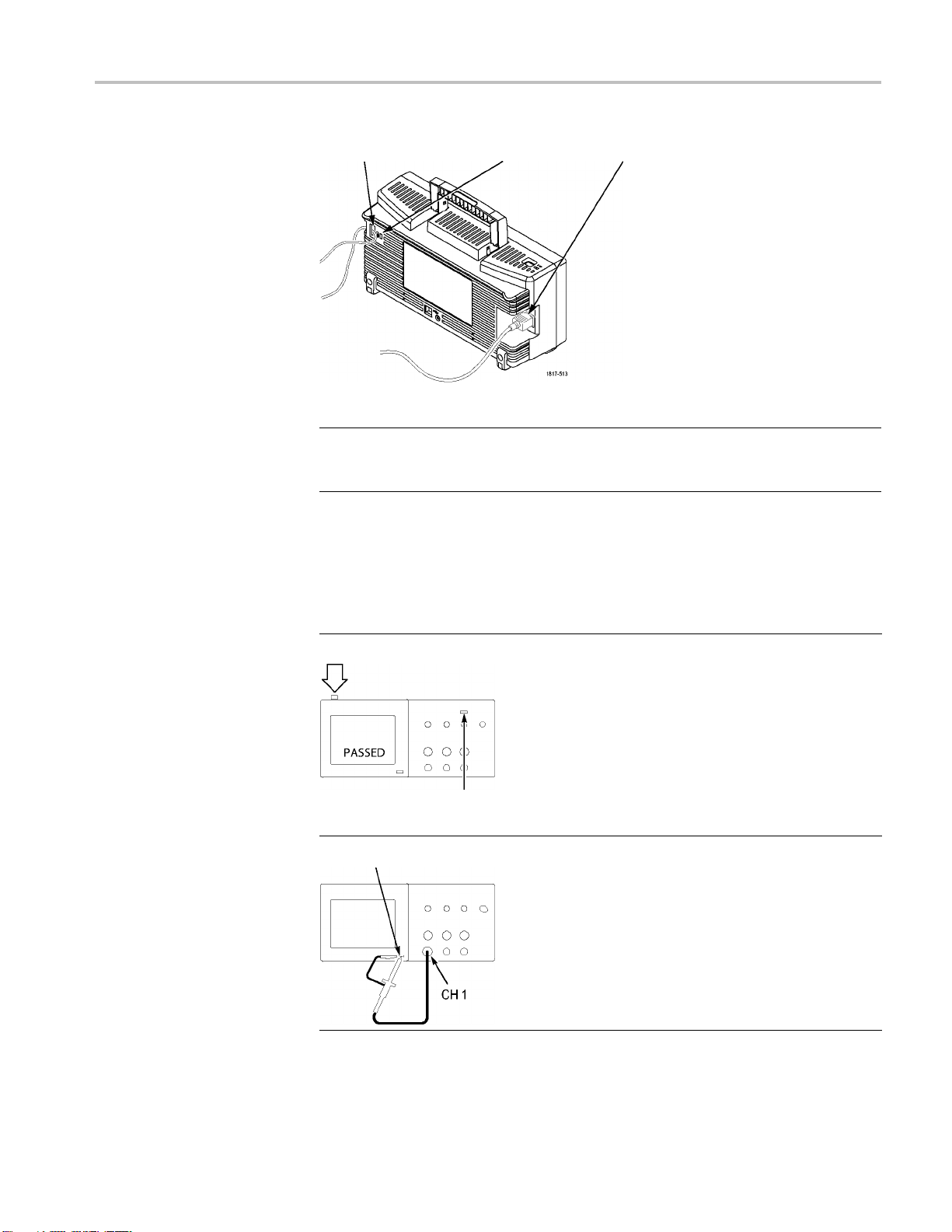
はじめに
通気
機能チェック
盗難防止ケーブル用の穴 盗難防止ロック用の穴
電源コード
注: このオシロスコープは、空気の自然対流によって冷却されます。オシロス
コープの両側面と上
面に 2 インチ(約 5 cm)のスペースを空けると、適切なエ
ア・フローが確保されます。
次の機能チェックを実行し、オシロスコープが正常に動作していることを確認
します。
ON/OFF(オン/オフ)ボタン
DEFAULT SETUP(工場出荷時設
定)ボタン
PROBE COMP(プローブ補正)
1. オシロスコープの電源をオンにします。
DEFAULT SETUP
ンを押します。
プローブ・オプションのデフォルトの減衰
設定は 10X です。
2. TPP0101 または TP0201 型プローブをオシ
ロスコープのチャンネル 1 に接続します。
接続するには、プローブのコネクタのスロッ
トと CH 1 BNC のキーを揃えて押し込み、
右に回して固定します。
プローブ・チップと基準リードを PROBE
COMP(プローブ補正)端子に接続します。
(工場出荷時設定)ボタ
TBS1000 Series Oscilloscopes Installation and Safety Manual 47

はじめに
プローブの安全性
3. AUTOSET(オートセット)ボタンを押します。
数秒以内に、約 5V p-p、周波数 1 KHz の
方形波がディスプレイに表
フロント・パネルの 1 (チャンネル 1 メ
ニュー)ボタンを 2 回押してチャンネル 1
を消去し、2 (チャンネ
ンを押してチャンネル 2 を表示します。次
に、手順 2 と手順 3 を繰り返します。
示されます。
ル2メニュー)ボタ
プローブを使用する前に、プローブの定格をチェックしてください。
TPP0101 および TPP0201 型プローブ本体には、感電を防ぐための指ガード
があります。
指ガード
警告: プローブ使用時の感電を避けるために、指はプローブ本体のガードの
後ろに置いてください。
プローブの使用中の感電を避けるために、プローブが電圧ソースに接続され
ている間はプローブ・ヘッドの金属部分に触らないでください。
プローブをオシロスコープに接続したら、接続を行う前にグランド端子をグラン
ドに接続します。
電圧プローブ・チェック・ウィザード
プローブ・チェック・ウィザードを使用すると、電圧プローブが正常に動作して
いることを確認できます。このウィザードは、電流プローブはサポートしていま
せん。
このウィザードは、電圧プローブを補正(通常はプローブ本体またはコネクタ
上にあるネジを使用)する場合や、各チャンネルの減衰オプション(1 ► Probe
(プローブ) ► Voltage(電圧) ► Attenuation(減衰)オプションなど)で定数を設
定する場合に役立ちます。
電圧プローブを入力チャンネルに接続するたびにプローブ・チェック・ウィザー
ドを実行してください。
48 TBS1000 Series Oscilloscopes Installation and Safety Manual

はじめに
プローブ・チェック・ウィザ
チェック)ボタンを押してください。電圧プローブが正しく接続され、正しく補正
され、またオシロスコープの Vertical(垂直軸)メニューの Attenuation(減衰)オ
プションがプローブに適合するように設定されていれば、オシロスコープのスク
リーン下部に PASSED(OK)メッセージが表示されます。そうでない場合、問題
を解決するための指示がスクリーンに表示されます。
注: プローブ・チェッ
ローブに使用できます。500X や 1000X のプローブ、または EXT TRIG(外部
トリガ)コネクタに接続されるプローブには使用できません。
注: プロセスが完了すると、プローブ・チェック・ウィザードは、Probe(プロー
ブ)オプション以外のオシロスコープ設定を、PROBE CHECK(プローブ・チェッ
ク)ボタンを押す前の状態に戻します。
EXT TRI
を実行します。
1. プローブを
2. PROB
G(外部トリガ)入力で使用するプローブの補正を行うには、次の手順
、いずれかの入力チャンネル・コネクタ(チャンネル 1 など)に
接続します。
ECHECK(プローブ・チェック)ボタンを押してスクリーンの指示に従
います。
ードを使用するには、PROBE CHECK(プローブ・
ク・ウィザードは、1X、10X、20X、50X、および 100X のプ
3. プロー
ブを EXT TRIG(外部トリガ)コネクタに接続します。
ブが機能していて適切に補正されていることを確認したら、プロー
TBS1000 Series Oscilloscopes Installation and Safety Manual 49
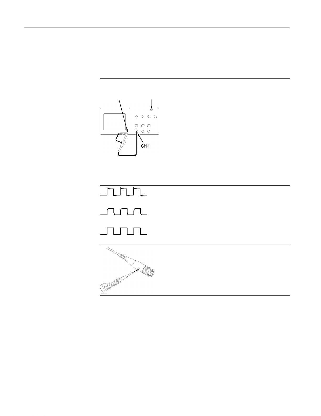
はじめに
プローブの手動補正
プローブ・チェック・ウィ
ザードを使用する代わりに、手動で調整を行って電圧
プローブを入力チャンネルに合わせることもできます。
PROBE COMP
(プローブ補正)
補正過多
AUTOSET
(オートセッ
ト)ボタン
1. 1 ► Probe(プローブ) ► Voltage(電圧) ►
Attenuation(減衰)オプションを押し、10X
を選択します。TPP0101 および TPP0201 型
プローブをオシロスコープのチャンネル 1
に接続します。プローブ・フックチップを使
用する場合は、チップをプローブにしっか
り差し込んで取り付け、適切に接続されて
いることを確認してください。
2. プローブ・チップを PROBE COMP(プローブ
補正)~5V@1kHz 端子に取り付け、基準リー
ドを PROBE COMP(プローブ補正)シャー
シ端子に取り付けます。チャンネルを表示
し、AUTOSET(オートセット)ボタンを押しま
す。
3. 表示される波形の形を確認します。
補正不足
適切な補正
4. 必要に応じて、プローブを調整します。
必要に応
じて手順を繰り返します。
50 TBS1000 Series Oscilloscopes Installation and Safety Manual
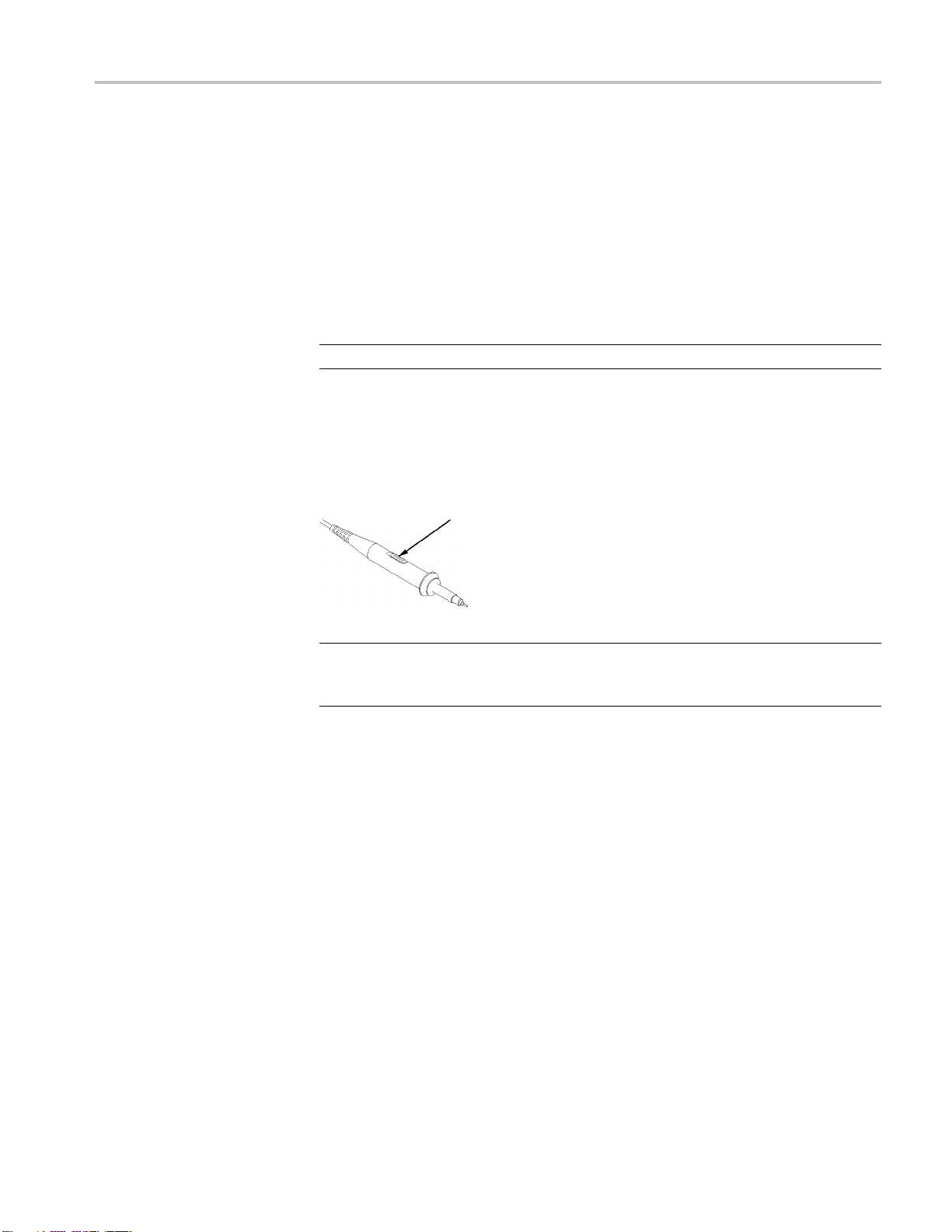
プローブの減衰設定
はじめに
プローブは、信号の垂直軸
ものが提供されています。プローブ・チェック・ウィザードは、オシロスコープの
減衰定数がプローブと適合しているかどうかを検査します。
プローブ・チェックの代わりに、使用するプローブの減衰に適合する定数を手
動で選択することもできます。たとえば、CH 1 に接続されているプローブを 10X
に設定する場合、1 ► Probe(プローブ) ► Voltage(電圧) ► Attenuation(減衰)
オプションを押し、10X を選択します。
注: Attenuation(減衰)オプションのデフォルト設定は 10X です。
P2220 型プ
にオシロスコープの Attenuation(減衰)オプションも変更する必要があります。
スイッチの設定は 1X と 10X です。
ローブ上の減衰比スイッチを変更した場合は、それに適合するよう
スケールに影響する、さまざまな減衰定数を持つ
減衰比スイッチ
注: 減衰比スイッチが 1X に設定されている場合、P2220 型プローブは、オシ
ロスコープの帯域幅を 6 MHz に制限します。オシロスコープの全帯域幅を使
用するには、スイッチを 10X に設定します。
電流プローブ・スケール
電流
電流プローブのスケールに適合するよう設定する必要があります。スケールの
デフォルト値は 10 A/V です。
たとえば、CH 1 に接続する電流プローブのスケールを設定するには、1 ► Probe
(プローブ) ► Current(電流) ► Scale(スケール)オプションを押し、適切な値
を選択します。
プローブは、電流に比例した電圧信号をもたらします。オシロスコープが
TBS1000 Series Oscilloscopes Installation and Safety Manual 51

はじめに
自己校正
自己校正ルーチンを使用してオシロスコープの信号パスを最適化することで、
測定の確度を高めることができます。ルーチンはいつでも実行できますが、周
囲温度が 5 ℃(9 ゚F)
実行にはおよそ 2 分かかります。
以上変化したときは必ず実行してください。ルーチンの
校正を正確に行うため
ム・アップが終了するまで待ってください。
信号パスを補正する
から外します。次に、Utility(ユーティリティ) ► Do Self Cal(自己校正)オプショ
ンを選択し、スクリーンの指示に従います。
、オシロスコープの電源をオンにしたら、20 分のウォー
には、まず、すべてのプローブとケーブルを入力コネクタ
インターネット経由のファームウェア更新
新しいバージョンのファームウェアが入手可能になった場合は、インターネット
と USB フラッシュ・ドライブを使用してオシロスコープを更新できます。インター
ネットにアクセスできない場合の更新手順については、販売店までご連絡くだ
さい。
インターネットからファームウェアを更新するには、次の手順を実行します。
1. Utility(ユーティリティ) ► System Status(システム・ステータス)オプションを
押し、オシロスコープのファームウェアのバージョン番号を書き留めます。
2. 自分のコンピュータから Web サイトの www.tektronix.com にアクセスし、よ
り新しいバージョンのオシロスコープ・ファームウェアが使用可能かどうか
を確認します。
3. 新しいバージョンのファームウェアがある場合は、Web ページからファーム
ウェア・ファイルをダウンロードします。
必要に応じて、ダウンロードしたファイルを解凍します。
4. ファームウェア・ファイルを USB フラッシュ・ドライブのルート・フォルダにコ
ピーします。
5. オシロスコープの前面にある USB フラッシュ・ドライブ・ポートに USB フラッ
シュ・ドライブを挿入します。
6. オシロスコープで、Utility(ユーティリティ) ► File Utilities(ユーティリティ) ►
- more - page 2 of 2(- 次へ - 2/2 ページ) ► Update Firmware(Firmware
の更新)オプション・ボタンを押します。
ファームウェアを更新するのに数分間かかります。
ファームウェアの更新が完了すると、任意のボタンを押すよう求められます。
ファームウェアの更新が完了するまでは、USB フラッシュ・ドライブを抜いたり、
オシロスコープの電源をオフにしないでください。
52 TBS1000 Series Oscilloscopes Installation and Safety Manual

基本操作
基本操作
フロント・パネルは、使い
コントロールおよびスクリーンに表示される情報について簡単に説明します。
やすいように機能別に分けられています。この章では、
TBS1000 Series Oscilloscopes Installation and Safety Manual 53
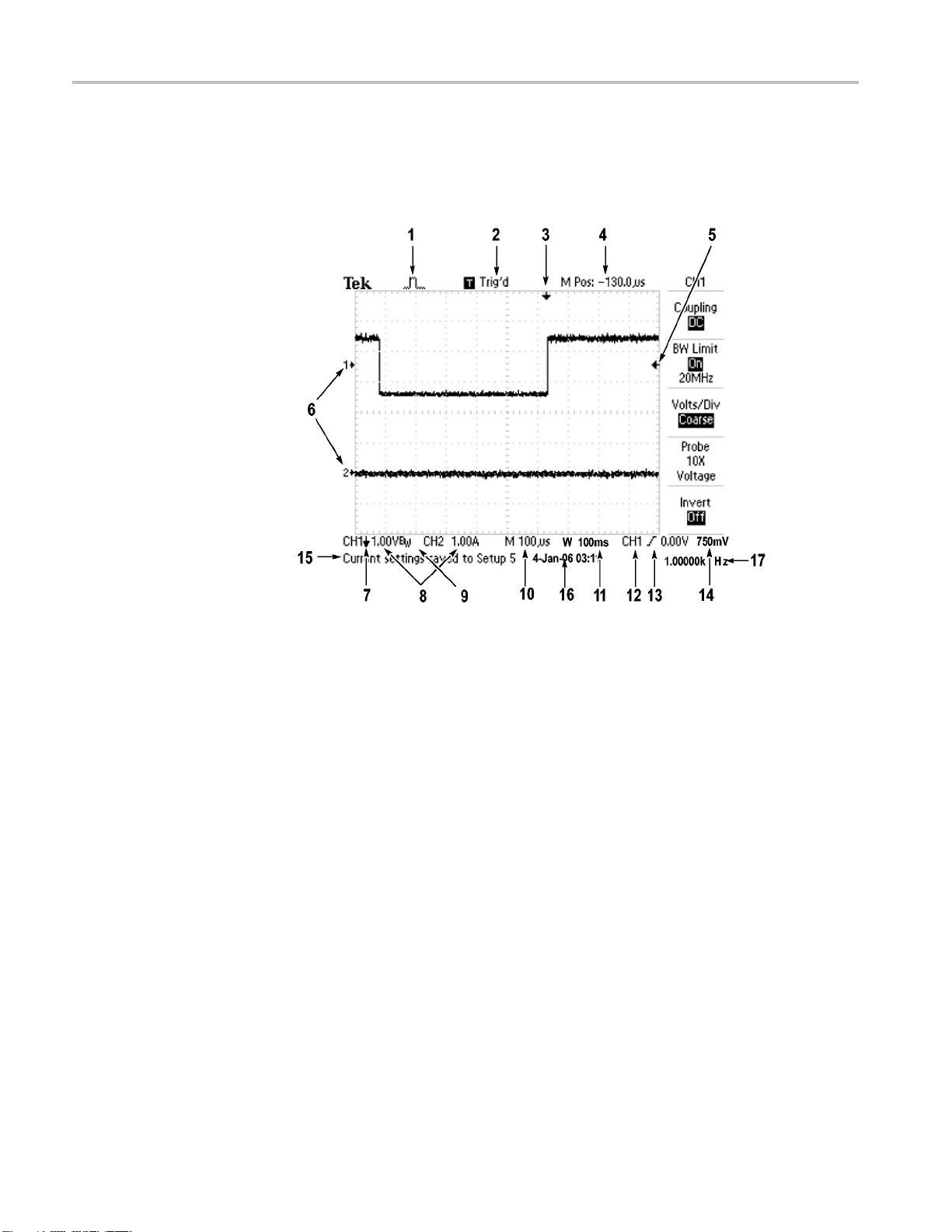
基本操作
表示領域
ディスプレイには、波形だけでなく、波形についてのさまざまな詳細情報や、
オシロスコープのコントロール設定も表示されます。
54 TBS1000 Series Oscilloscopes Installation and Safety Manual
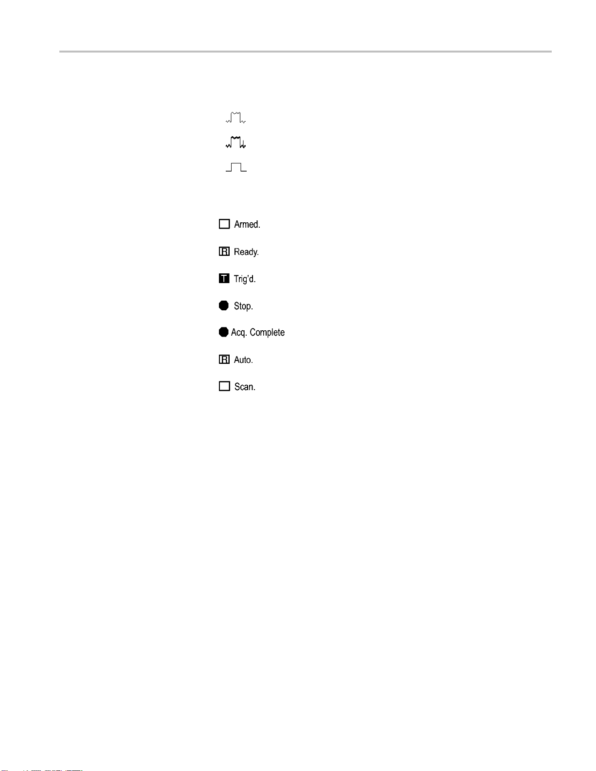
基本操作
1. このアイコン表示は、アクイ
サンプル・モード
ピーク検出モード
アベレージング・モード
ジション・モードを示します。
2. トリガ・ステータスは、次の状態を示しています。
オシロスコープは、プリトリガ・データを取り込んでいま
す。この状態では、すべてのトリガは無視されます。
すべてのプリトリガ・データが取り込まれ、オシロスコー
プはトリガを受け入れられる状態になっています。
オシロスコープはトリガを検出し、ポストトリガ・データを
取り込んでいます。
オシロスコープは、波形データの取り込みを停止し
ました。
オシロスコープは、シングル・シーケンスのアクイジショ
ンを完了しました。
オシロスコープはオート・モードであり、トリガなしで波
形を取り込んでいます。
オシロスコープは、スキャン・モードで連続的に波形
データを取り込んで表示しています。
3. このマーカは、水平トリガ位置を示します。マーカの位置を調整するには、
Horizontal(水平軸)の Position(位置)ノブを回します。
4. このリードアウトは、中央の目盛の時間を
示します。トリガ時間がゼロです。
5. このマーカは、エッジまたはパルス幅のトリガ・レベルを示します。
6. このスクリーン上のマーカは、表示されている波形のグランド基準ポイント
を示します。マーカがない場合、チャンネルは表示されません。
7. この矢印アイコンは、波形が反転されていることを示します。
8. このリードアウトは、チャンネルの垂直軸スケール・ファクタを示します。
9. B
アイコンは、チャンネルの帯域幅が制限されていることを示します。
W
10. このリードアウトは、メイン時間軸の設定を示します。
11. このリードアウトは、ウィンドウ時間軸の設定(使用されている場合)を示し
ます。
12. このリードアウトは、トリガに使用されているトリガ・ソースを示します。
13. このアイコンは、選択されているトリガの種類を示します。次の種類がありま
す。
TBS1000 Series Oscilloscopes Installation and Safety Manual 55

基本操作
メッセージ領
域
立上りエッジに対するエッジ
立下りエッジに対するエッ
ライン同期に対するビデオ・トリガ
フィールド同期に対するビ
パルス幅トリガ、正極性
パルス幅トリガ、負極性
・トリガ
ジ・トリガ
デオ・トリガ
14. このリードアウトは、エッジまたはパルス幅のトリガ・レベルを示します。
15. 表示領域には、役に
立つメッセージが表示されます。一部のメッセージは
3 秒間だけ表示されます。
保存されている波
形を呼び出すと、このリードアウトには、"RefA 1.00V
500µs" のように、リファレンス波形についての情報が表示されます。
16. このリードアウ
トは、日付と時刻を示します。
17. このリードアウトは、トリガ周波数を示します。
オシロスコープのスクリーンの下部にあるメッセージ領域(前図の項目番号 15)
には、次のような役に立つ情報が表示されます。
他のメニューへのアクセス方法。たとえば、TRIG MENU ボタンを押すと、
次のコメントが表示されます。
ホールドオフは水平軸メニューで設定してください。
次に必要と思われる操作。たとえば、Measure(波形測定)ボタンを押すと、
次のコメントが表示されます。
オプションボタンを押して項目を変更してください。
オシロスコープが実行した動作を示す情報。たとえば、DEFAULT SETUP
(工場出荷時設定)ボタンを押すと、次のコメントが表示されます。
初期設定が呼出されました。
波形に関する情報。たとえば、AUTOSET(オートセット)ボタンを押すと、次
のコメントが表示されます。
CH1 で方形波またはパルスを検出しました。
56 TBS1000 Series Oscilloscopes Installation and Safety Manual

メニュー・システムの使用
オシロスコープのユーザ・インタフェースは、メニュー構造を通して特定の機能
に簡単にアクセスできるよう設計されています。
フロント・パネル・ボタンを押すと、オシロスコープのスクリーンの右側に、対応
するメニューが表示されます。メニューでは、スクリーンの右側にあるラベル表
示のないオプション・ボタンを押したときに使用できるオプションが示されます。
メニュー・オプションを表示するには、複数の方法があります。
ページ(サブメニュー)の選択:一部のメニューには、上のオプション・ボタ
ンを押してサブメニューを選択する形式のものがあります。上のオプション・
ボタンを押すたびに、サブメニューのオプションが切り替わります。たとえ
ば、Trigger(トリガ)メニューの一番上のオプション・ボタンを押すと、サブメ
ニューの表示が
り替わります。
基本操作
Edge(エッジ)、Video(ビデオ)、Pulse(パルス)の順に切
循環リスト:オ
ます。たとえば、1(チャンネル 1 メニュー)ボタンを押し、続いて一番上の
オプション・ボタンを押すと、垂直軸(チャンネル)の Coupling(入力結合)
オプションが順番に切り替わります。
リストによっては、汎用ノブを使用してオプションを選択できます。汎用ノブ
が使用できる場合はヒント・ラインに示され、汎用ノブが有効のときは、ノブ
の横にある LED が点灯します。
プション・ボタンを押すたびに、パラメータは違う値に設定され
TBS1000 Series Oscilloscopes Installation and Safety Manual 57
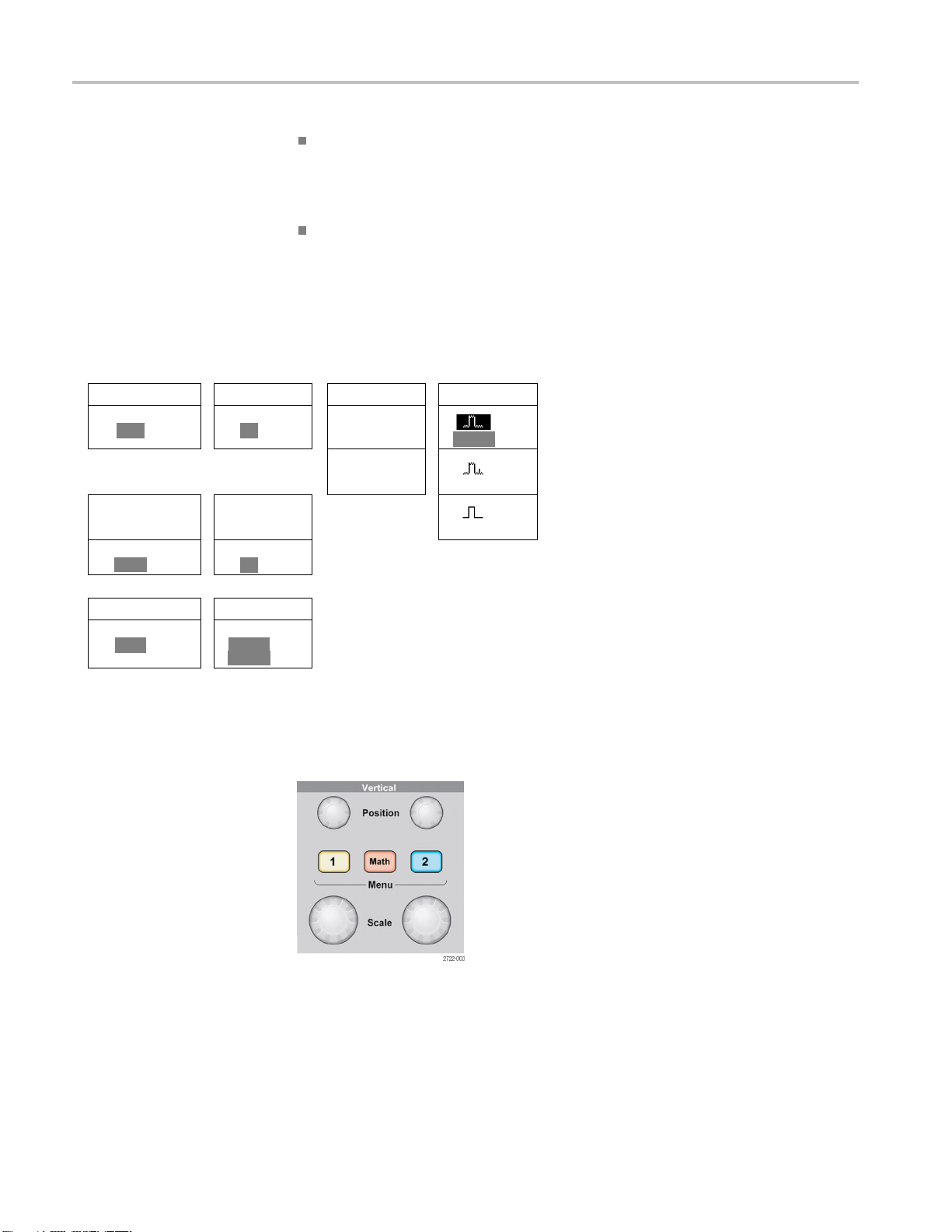
基本操作
ページの選択
TRIGGER CH1
Type
Edge
または または
TRIGGER CH1
Type
Video
または または
TRIGGER CH1
Type
Pulse
循環リスト
Coupling
DC
Coupling
AC
Coupling
Ground
(GND)
アクション:Action(
アクション)オプション・ボタンを押すとただちに実行され
るアクションの種類が表示されます。たとえば、ヘルプの索引が表示されて
いる状態で Page Down(次ページ)オプション・ボタンを押すと、索引項目
の次のページがただちに表示されます。
選択メニュー:このオシロスコープでは、オプションごとに複数の選択ボタ
ンが表示されます。現在選択されているオプションがハイライトされます。
たとえば、Acquire(波形取込)メニュー・ボタンを押すと、さまざまなアクイジ
ション・モードのオプションが表示されます。オプションを選択するには、対
応するボタンを押し
アクション
HELP
Page
Up
Page
Down
ます。
選択メ
ニュー
ACQUIRE
Sample
Peak Detect
Average
垂直軸コントロール
垂直軸のオーバーレンジ(クリッピング): 測定のリードアウトに ? が表示され
た場合は、無効な値であることを示しています。これは、波形がスクリーンの範
58 TBS1000 Series Oscilloscopes Installation and Safety Manual
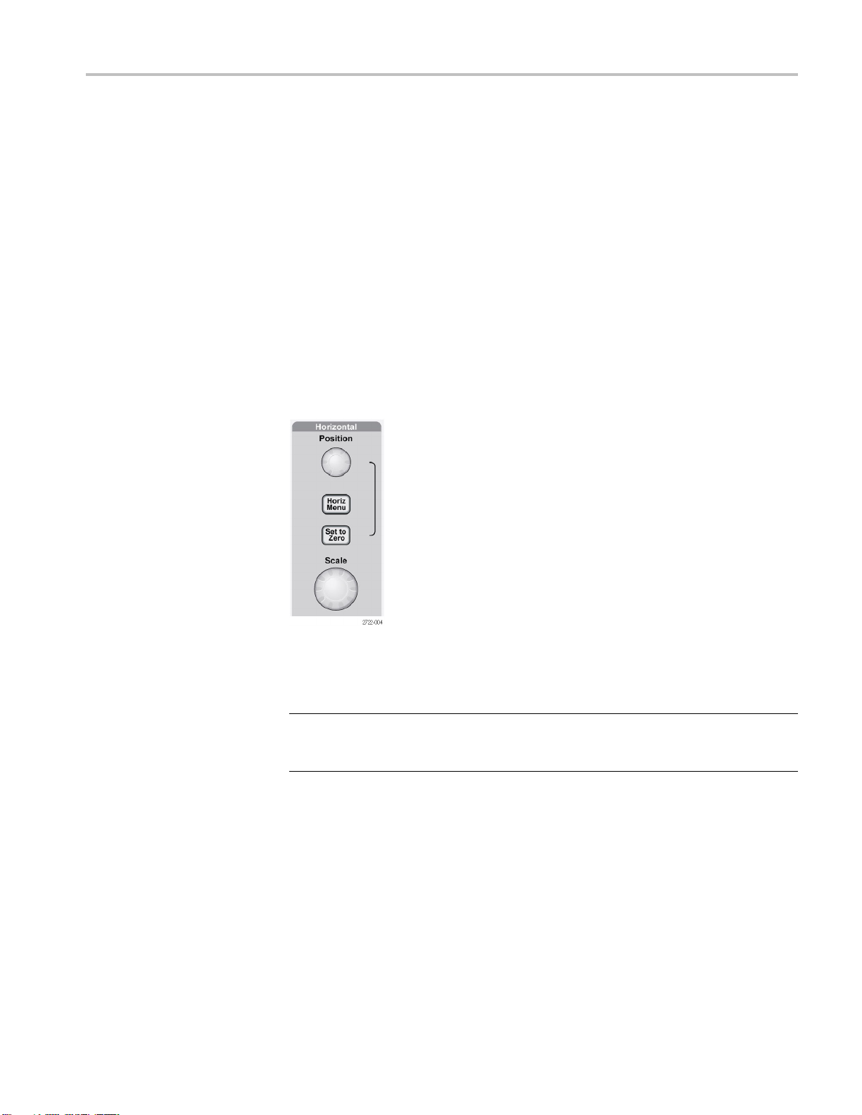
基本操作
水平軸コントロール
囲を超えている(オーバーレ
有効になるように垂直軸のスケールを調整してください。
Position(位置)(1、2): 波形の垂直方向の位置を指定します。
1 、2 Menu(メニュー): 垂直軸のメニュー項目を表示し、チャンネル波形の表
示のオンとオフを切り
Scale(スケール)(1、2): 垂直軸スケール・ファクタを選択します。
Math(演算): 波形演算操作メニューを表示し、演算波形の表示のオンとオフ
を切り替えます。
替えます。
ンジ)ために起きる場合があります。リードアウトが
Position(位置): すべてのチャンネルおよび演算波形の水平位置を調整しま
す。このコントロールの分解能は、時間軸の設定によって異なります。
注: 水平位置を大きく調整するには、Horizontal(水平軸)の Scale(スケール)
大きな値にし、水平位置を変更した後、Horizontal(水平軸)の Scale(ス
ノブを
ケール)ノブを元の値に戻します。
Horiz: Horizontal Menu(水平軸メニュー)を表示します。
Set to Zero(標準位置): 水平位置をゼロに設定します。
Scale(スケール): メイン時間軸またはウィンドウ時間軸の、1 目盛当たりの水
平時間(スケール・ファクタ)を選択します。Window Zone(範囲指定)が有効に
なっている場合は、ウィンドウの時間軸を変化させてウィンドウ・ゾーンの幅を
変更します
TBS1000 Series Oscilloscopes Installation and Safety Manual 59

基本操作
トリガ・コントロール
Level(レ ベル): エッジ・トリガまたはパルス・トリガを使用しているときには、
Level(レベル)ノブは、波形を取り込むために信号が超える必要のある振幅レ
ベルを設定します。
TRIG MENU: Trigger Menu(トリガ・メニュー)が表示されます。
Set To 50%(50% 振幅): トリガ・レベルを、トリガ信号のピーク間の垂直方向の
中央に設定します。
Force T
ます。このボタンは、アクイジションがすでに停止している場合は無効です。
TRIG VIEW(トリガ波形表示): このボタンを押している間は、チャンネル波形
の代わりにトリガ波形が表示されます。 トリガ・カップリングなど、トリガ設定がト
リガ信号に与える影響を確認するために使用します。
rig(強制トリガ): トリガ信号の有無に関係なく、アクイジションを完了し
メニュー・ボタンとコントロール・ボタン
ブ
汎用ノ
60 TBS1000 Series Oscilloscopes Installation and Safety Manual

基本操作
メニューおよびボタン・コン
トロールの詳細については、「リファレンス」の章を
参照してください。
汎用ノブ: このノブの機能は、表示されているメニューや選択されているメ
ニュー・オプションによって異なります。有効になると、横にある LED が点灯し
ます。次の表に、ノブの機能を示します。
有効なメニューまた
はオプション ノブの機能 説明
Cursor(カーソル)
Help(ヘルプ)
Horizontal(水平軸)
演算
Measure(波形測定)
Save/Recall(保存/
呼出)
Trigger(トリガ部)
カーソル 1 また
はカーソル 2
スクロール
ホールドオフ
位置
垂直軸スケール
種類
アクション
ファイル選択
ソース
ビデオ・ライン番
号
パルス幅 トリガの種類オプションが Pulse
選択されているカーソルの位置
を指定します。
索引の項目を選択し、トピックの
リンクを選択します。トピックの次
ページまたは前ページを表示し
ます。
別のトリガ・イベントを受け付ける
までの時間を設定します。
演算波形の位置を指定します。
演算波形のスケールを変更しま
す。
ソースごとに自動測定の種類を
選択します。
その操作を、セットアップ・ファイ
ル、波形ファイル、およびスクリー
ン・イメージの保存または呼び出
しとして設定します。
保存するセットアップ・ファイル、
波形ファイル、またはイメージ・
ファイルを選択したり、呼び出す
セットアップ・ファイルまたは波形
ファイルを選択します。
トリガの種類オプションが Edge
(エッジ)に設定されている場合
に、ソースを選択します。
トリガの種類オプションが Video
(ビデオ)に設定され、Sync(同
期)オプションが Line Number
(Line 番号)に設定されている場
合は、オシロスコープを特定のラ
イン番号に設定します。
(パルス)に設定されている場合
は、パルスの幅を設定します。
TBS1000 Series Oscilloscopes Installation and Safety Manual 61

基本操作
有効なメニューまた
はオプション ノブの機能 説明
Utility(ユ ー ティ リ
ティ ) ► File Utilities
(ユーティリティ)
Utility(ユ ー テ
ティ) ► Options(オ
プション) ► GPIB
Setup(GPIB
Address(アドレス)
Utility(ユ
ティ) ► Options(オプ
ション) ► Set Date and
Time(日時の設
Vertical( 垂 直部 )
► Probe( プ
►Voltage(電圧)►
Attenuation(減衰)
Vertical( 垂 直部 )
► Probe( プ ローブ)
► Curren
Scale(スケール)
ィリ
設定) ►
ーティリ
定)
ローブ)
t(電流) ►
ファイル選択
名前入力 ファイルまたはフォルダの
値入力
値入力 日付と時刻の値を設
値入力
値入力
名前の変更または削除を行うファ
イルを選択します。
変更します。
TEK-USB-488 型アダプタの
GPIB アドレスを設定します。
チャンネル・メニ
ニューなど)で、オシロスコープの
減衰定数を設定します。
チャンネル・メニュー(CH 1 メ
ニューなど)で
スケールを設定します。
名前を
定します。
ュー(CH 1 メ
、オシロスコープの
AUTORANGE(オートレンジ): Autorange Menu(オートレンジ・メニュー)を表
示し、オートレンジ機能を有効または無効にします。オートレンジ機能が有効
になると、横にある LED が点灯します。
SAVE/RECALL(保 存 /呼出) : セットアップと波形についての Save/Recall
Menu(保存/呼出メニュー)が表示されます。
Measure(波形測定): 自動測定メニューが表示されます。
Acquire(波形取込): Acquire Menu(波形取込メニュー)が表示されます。
Ref(REF メニュー): オシロスコープの不揮発性メモリに保存されているリファレ
ンス波形をすばやく表示または非表示にする、Reference Menu(REF メニュー)
を表示します。
Utility(ユーティリティ): Utility Menu(ユーティリティ・メニュー)が表示されま
す。
Cursor(カーソル): Cursor Menu(カーソル・メニュー)が表示されます。Cursor
Menu(カーソル・メニュー)を終了してもカーソルは表示されていますが(Type
(項目)オプションが Off(オフ)に設定されていない場合)、カーソルを調節す
ることはできません。
Display(表示): Display Menu(表示メニュー)が表示されます。
62 TBS1000 Series Oscilloscopes Installation and Safety Manual

基本操作
入力コネクタ
Help(ヘルプ): Hel
DEFAULT SETUP(工場出荷時設定): 出荷時セットアップが呼び出されます。
AUTOSET(オートセット): 入力信号の表示が最適になるように、オシロスコー
プの制御を自動的に設定します。
Single(単発波形): (シングル・シーケンス)単一の波形を取り込んだ後、停止
します。
RUN/STOP(実行/停止): 波形を連続して取り込むか、アクイジションを停止
します。
PictBridge 互換プリンタへの印刷操作を開始するか、USB フラッシュ・ドライ
ブへの保存機能を実行します。
Save(保存): USB フラッシュ・ドライブにデータを保存するようにPrint(印刷)
ボタンが設定されていると、LED が点灯します。
p(ヘルプ)メニューが表示されます。
1&2: 波形表示用の入力コネクタです。
EXT TRIG(外部トリガ): 外部トリガ・ソース用の入力コネクタです。トリガ・ソー
ス(Ext または Ext/5)を選択するには、Trigger Menu(トリガ・メニュー)を使用
します。トリガ・カップリングなど、トリガ設定がトリガ信号に与える影響を確認す
は、TRIG VIEW(トリガ波形表示)ボタンを押し続けます。
るに
フロント・パネルのその他のコネクタ
USB フラッシュ・ドライブ・ポート
TBS1000 Series Oscilloscopes Installation and Safety Manual 63

基本操作
USB フラッシュ・ドライブ
ラッシュ・ドライブを挿入します。フラッシュ・ドライブが有効なときには、オシロ
スコープに時計の記号が表示されます。ファイルが保存または取得されると、
オシロスコープでは時計の記号が消え、保存や呼び出しの操作が完了したこ
とを知らせるヒント・ラインが表示されます。
LED 付きのフラッシュ・ドライブの場合、ドライブに対してデータの保存や取得
を行っているときには LED が点滅します。LED の点滅が停止するまで待って
ドライブを抜いてください。
PROBE COMP(プローブ補正): プローブ補正出力およびシャーシの基準で
す。電圧プローブをオシロスコープの入力回路と電気的に一致させるために
使用します。
・ポート: データの保存や取り出しのために USB フ
PC への PC 通信ソフトウェアのインストール
Tektronix OpenChoice PC 通信ソフトウェアを使用してオシロスコープを PC に
接続する前に、www.tektronix.com/software からソフトウェアをダウンロードし、
PC にインストールします。
注意: オシ
ルすると、オシロスコープは PC に認識されません。オシロスコープは不明なデ
バイスとして識別されるため、PC とオシロスコープとの通信は行われません。
これを防ぐには、通信ソフトウェアを PC にインストールしてから、オシロスコー
プを PC に接続します。
ロスコープを PC に接続してから PC 通信ソフトウェアをインストー
注: 最新バージョンの PC 通信ソフトウェアがインストールされていることを確
てください。
認し
オシロスコープ用ソフトウェアは、当社のソフトウェア・ファインダ・ホームページ
入手できます。
から
PC 通信ソフトウェアをインストールするには、次の手順を実行します。
1. PC で OpenChoice ソフトウェアを実行します。InstallShield ウィザードが画
面に表示されます。
2. スクリーンの指示に従ってください。
3. InstallShield ウィザードを終了します。
64 TBS1000 Series Oscilloscopes Installation and Safety Manual

PC への接続
基本操作
ソフトウェアを PC にインストールしたら、オシロスコープを PC に接続できます
(64ページ「PCへのPC通信ソフトウェアのインストール」参照)。
注: ソフトウェアはオシロスコープを PC に接続する前にインストールする必要
があります。
オシロスコープを PC に接続するには、次の手順を実行します。
1. オシロスコープの電源をオンにします。
2. USB ケーブルの片側を、オシロスコープの後部にある USB デバイス・ポー
トに挿入します。
3. PC の電源をオンにします。
4. ケーブルの逆側を、PC 上の USB ポートに挿入します。
5. "新しいハー
は、新しいハードウェアの検出ウィザードによって示されるスクリーンの指
示に従ってください。
インストールするハードウェアを Web で検索しないでください。
ドウェアが見つかりました" というメッセージが表示された場合
TBS1000 Series Oscilloscopes Installation and Safety Manual 65

基本操作
6. Windows XP システム
a. Tektronix PictBridge Device(Tektronix PictBridge デバイス)ダ イ アロ
グ・ボックスが表示された
す。
b. メッセージが表示され
するオプションを選択し、Next(次へ)をクリックします。
c. 次のウィンドウには、
アをインストール中であるというメッセージが表示されます。USB Test
and Measurement Device 用のソフトウェアが表示されない場合は、
OpenChoice デスクトップ・ソフトウェアが正しくインストールされていま
せん。
d. ソフトウェアを自動的にインストールするオプション(推奨されるオプショ
ン)を選択し、Next(次へ)をクリックします。
Windows によってオシロスコープのドライバがインストールされます。
e. 手順 c で USB Test and Measurement Device が表示されない場合や、
Windows でソフトウェア・ドライバが見つからない場合は、OpenChoice
デスクトップ・ソフトウェアが正しくインストールされていません。
このような場合は、Cancel(キャンセル)をクリックして新しいハードウェ
アの検出ウィザードを終了します。ウィザードが完了しないようにしてく
ださい。
の場合は、次の手順を実行します。
場合には、Cancel(キャンセル)をクリックしま
たら、Windows Update に接続しないことを指定
USB Test and Measurement Device 用のソフトウェ
オシロスコープから USB ケーブルを抜き、OpenChoice デスクトップ・ソ
フトウェアをインストールします。
オシロスコープをもう一度 PC に接続し、手順 6a、6b、6c、および 6d を
実行します。
f. Finish(終了)をクリックします。
g. Test and Measurement Device というタイトルのダイアログが表示された
ら、Windows で実行する処理を選択して OK をクリックします。
66 TBS1000 Series Oscilloscopes Installation and Safety Manual

基本操作
7. Windows 2000 シス
a. メッセージが表示されたら、既知のドライバのリストを表示することを指
定するオプションを選択し
b. 次のウィンドウで、USB Test and Measurement Device を選択します。
USB Test and
は、OpenChoice デスクトップ・ソフトウェアが正しくインストールされて
いません。
c. 次のウィンドウで、Next をクリックしてオシロスコープのドライバをインス
トールします。
Windows によってオシロスコープのドライバがインストールされます。
d. 手順 b で USB T
Windows でソフトウェア・ドライバが見つからない場合は、ソフトウェアが
正しくインストールされていません。
このような場合は、Cancel(キャンセル)をクリックして新しいハードウェ
アの検出ウィザードを終了します。ウィザードが完了しないようにしてく
ださい。
オシロスコープから USB ケーブルを抜き、ソフトウェアをインストールし
ます。
テムの場合は、次の手順を実行します。
、Next(次へ)をクリックします。
Measurement Device の選択項目が表示されない場合
est and Measurement Device が表示されない場合や、
オシロスコープをもう一度 PC に接続し、手順 7a、7b、および 7c を実
行します。
8. メッセージが表示されたら、Finish(終了)をクリックします。
9. CD の挿入を要求されたら、Cancel(キャンセル)をクリックします。
10.PC
11. オシロスコープと PC が互いに通信しない場合は、PC 通信ソフトウェアの
側で PC 通信ソフトウェアを実行します。
ライン・ヘルプとドキュメントを参照してください。
オン
TBS1000 Series Oscilloscopes Installation and Safety Manual 67

仕様
仕様
ここでは、TBS1000
び TPP0201 型プローブの仕様については付録 B で説明します。オシロスコー
プが仕様に準拠するには、まず、次の条件が満たされている必要があります。
すべての仕様は、"代表値" と記載されていないかぎり、保証値です。
オシロスコープの仕様
表 6: 入力仕様
特性 説明
最大入力電圧
フロント・パネル・コネクタでは 300 VRMS、測定カテゴリ II。100 KHz を超えると 20 dB/decade で低下し、3
MHz 以上では 13 V ピーク AC まで
正弦波信号または DC 入力信号に基づきます。DC カップリング時に視認可能な最大信号は、±50 V オフ
セット ±5 V/div(4 目盛)、または 70 V です。AC カップリングでは、DC ~ 300 V までの範囲の信号を測定
できます。非正弦波形では、ピーク
満、デューティ・ファクタは < 44% に制限されています。RMS 信号レベルは 300 V に制限されています。これ
らの値を超えると機器が損傷する場合があります。
シリーズ・モデルに共通の仕様を示します。TPP0101 型およ
オシロスコープは、指定された動作温度範囲内で 20 分間連続して動作
する必要があります。
動作時の温度が 5 ℃(9 ゚F) 以上変化する場合は、Utility(ユーティリティ)
メニューからアクセスできる Do Self Cal(自己校正)操作を実行する必要が
あります。
オシロスコープは工場校正の間隔内にある必要があります。
低下。
値は 450 V 未満である必要があります。300 V を超える偏位は 100 ms 未
表 7: 一般仕様
特性
プローブ補正器出力
プローブ補正器、出力電圧
および周波数、代表値
電源
電源電圧
電力消費量
環境条件
温度
冷却方法 対流冷却
説明
特性は次のとおりです。
出力電圧 1 Meg Ω の負荷に 5.0 V ±10%
周波数 1 KHz
フル・レンジ:100 ~ 240 VAC RMS ±10%、測定カテゴリ II(90 ~ 264 VAC レンジをカバー);50/60 Hz
115 VAC RMS ±10%;400 Hz
30 W 未満(90 ~ 264 VAC 入力)
動作時 0 ℃ ~ +50 ℃、最大勾配 5
非動作時 -40 ℃ ~ +71 ℃、最大勾配 5
℃/min、結露なし、高度 3,000 m
以下
℃/min
68 TBS1000 Series Oscilloscopes Installation and Safety Manual

TPP0101 および TPP0201 シリーズ受動プローブ(100 MHz/200 MHz 10X)に関する情報
表 7: 一般仕様, (続き)
特性
湿度:動作時および非動作
時
使用可能高度:動作時およ
び非動作時
機械特性
全寸
重量
説明
動作時
非動作時
動作時 3,000 m(10
非動作時 3,000 m(10,000 フィート )以 下
以下の要件は公称です。
高さ 158.0 m
幅
奥行き 124.1 mm(4.88 イン チ)
以下の要件
単体
アクセサリ
国内出荷向け梱包質量
は公称です。
搭載時
+40 ℃ 以下で 5% ~ 85% の相対湿度(RH)
+40 ℃ 超、+50 ℃
湿球温度 +37 ℃(+50 ℃で相対湿度は 45 % に低下)
+40 ℃ 以下で 5% ~
+40 ℃ 超、+50 ℃ 以下で 5% ~ 45% の相対湿度(RH)、結露なし。
+50 ℃ 超で最高湿球温度 +37 ℃(+71 ℃ で相対湿度は 12% に低下)
高度が高くなると LCD が損傷を受ける可能性が高くなります。この損傷
は機器の操作とは
以下で 5% ~ 45% の相対湿度(RH)、結露なし。最高
85% の相対湿度(RH)、
,000 フィート)以 下
無関係です。
m(6.22インチ)
326.3 mm(12.85 インチ)
2.0 kg(4.4 ポ ンド )
(4.9 ポンド)
2.2 kg
3.6kg(8ポンド)
TPP
0101 および TPP0201 シリーズ受動プローブ(100
MHz/200 MHz 10X)に関する情報
TPP0101 および TPP0201 シリーズの 10X 受動プローブは、10 X 減衰、高イ
ンピーダンスの受動プローブです。これらのプローブは TBS1000 シリーズの
ロスコープ用に設計されています。これらのオシロスコープの入力容量は
オシ
20 pF です。
ローブの補正レンジは 15 ~ 25 pF です。
プ
これらのプローブには、お客様や当社で修理できる部品はありません。
警告: TPP0101 または TPP0201 シリーズのプローブは、オシロスコープの機
種を問わず、浮かせた状態では使用しないでください。
TBS1000 Series Oscilloscopes Installation and Safety Manual 69

TPP0101 および TPP0201 シリーズ受動プローブ(100 MHz/200 MHz 10X)に関する情報
プローブとオシロスコープの接続
プローブの補正
以下の図に示すようにプロ
オシロスコープの入力特性には個々に差異があるため、オシロスコープ上で
プローブをあるチャンネルから別のチャンネルに接続し直した後は、プローブ
の低周波数補正を調節しなければならない場合があります。
校正済みの 1 KHz 方形波(1 ms/div で表示)の立上りエッジと立下りエッジの
間で顕著な差異が認められる場合は、以下の手順を実行して低周波数補正
を最適化し
てください。
ーブを接続します。
1. 測定に使用するオシロスコープのチャンネルにプローブを接続します。
2. オシロスコープのフロント・パネルにあるプローブ補正出力端子にプロー
ブを接続します。
警告:
この調節を行うときのみにしてください。
3. Autoset(オートセット)を押すか、その他の方法でオシロスコープを調節し、
4. 上部が完全に平坦な方形波(下図を参照)がディスプレイに表示されるま
警告: 感電を避けるため、補正値の調節には絶縁の施された調節ツールの
みを使用してください。
感電を避けるために、オシロスコープの Probe Comp 信号への接続は、
安定した波形表示が得られるようにします。
で、プローブのトリマを調整します。
70 TBS1000 Series Oscilloscopes Installation and Safety Manual

TPP0101 および TPP0201 シリーズ受動プローブ(100 MHz/200 MHz 10X)に関する情報
プローブと測定回路の接続
被測定回路との接続には、プローブに付属のスタンダード・アクセサリを使用
します。
警告: プローブやアクセサリの使用時の感電を避けるために、プローブ本体
やアクセサリの指ガードの先には絶対に指を出さないようにしてください。
感電を避けるため、プローブを被測定回路に接続する前に、グランド・リードと
グランド・スプリングが完全に噛み合っていることを確認してください。
TBS1000 Series Oscilloscopes Installation and Safety Manual 71

TPP0101 および TPP0201 シリーズ受動プローブ(100 MHz/200 MHz 10X)に関する情報
スタンダード・アクセサリ
プローブに付属しているアクセサリを下記に示します。
項目 説明
カラー・バンド
オシロスコープのチャンネルを色
で識別できるよう、プローブ・ヘッ
ドに装着します。
追加注文時の当社部品番号:
016-0633-xx(5 対)
フック・チップ
フック・チップをプローブ・チップ
にかぶせ、次にフッ
続します。
追加注文時の当社部品番号:
013-0362-xx
ワニ口クリップ付きグランド・リード
リードを確実にプローブ・ヘッドの
グランドに接続
ランドに接続します。
クを回路に接
し、次に回路のグ
追加注文時の当社部品番号:
196-3521-xx
グランド・スプリング
接地経路の
高周波信号のアベレーションを最
小限に抑え、高い信号忠実度で
の測定を
スプリングをプローブ・チップのグ
ランド・バンドに取り付けます。ス
プリング
イントから最大 0.75 インチまで離
すことができます。
追加注
016-2028-xx(2 個)
調整ツール
追加注文時の当社部品番号:
-1433-xx
003
インダクタンスによる
可能にします。
を曲げて、信号テスト・ポ
文時の当社部品番号:
72 TBS1000 Series Oscilloscopes Installation and Safety Manual

TPP0101 および TPP0201 シリーズ受動プローブ(100 MHz/200 MHz 10X)に関する情報
オプショナル・アクセサリ
仕様
プローブのオプショナル・
アクセサリ 部品番号
ワニ口付きグランド・リ
6 インチ・クリップオン・グランド・リード
グランド・スプリング(短)(2 個)
MicroCKT テ
マイクロ・フック・チップ
ユニバーサル IC キャップ
回路基板テスト・ポイント/PCB アダプタ
ワイヤ・スプール
スト・チップ
、32 AWG
アクセサリ(別途注文品)を以下に示します。
ード(12 インチ)
196-3512-xx
196-3198-xx
016-2034-xx
206-0569-xx
013-0363-xx
013-0366016-2016-xx
020-3045-xx
xx
表 8: 電気仕様と機械仕様
特性 TPP0101 型 TPP0201 型
RMS
MHz
CAT II
DC ~ 200
TPP0201 型:
15 pF ~ 25 pF
3ns
<2.
V
RMS
CAT II
300
帯域(-3 d
システム減衰
補正レンジ
システム入力抵抗 @DC
システム
システム立上り時間(代
表値)
伝搬遅
最大入力電圧
ケーブル長
B)
確度
入力容量
延
DC ~ 100
10:1 ±3.2% 10:1 ±3.2%
TPP0101 型:
15 pF ~ 25 pF
10 MΩ ±1.5% 10 MΩ ±1.5%
<12 pF <12 pF
5ns
<3.
~6.1ns ~6.1ns
V
300
1.3 m 1.3 m
MHz
TBS1000 Series Oscilloscopes Installation and Safety Manual 73

TPP0101 および TPP0201 シリーズ受動プローブ(100 MHz/200 MHz 10X)に関する情報
表9: 環境仕様
特性 説明
温度
動作時
非動作時
湿度
動作時および非動作
時
高度
動作時
非動作時
-10 ℃ ~ +55 ℃(14
-51 ℃~ +71 ℃(-60 ゚F ~ +160 ゚F)
+30 ℃(86 ゚F)以下で相対湿度 5% ~ 95%、+30 ℃ ~
+55 ℃(131 ゚F
最高 3.0 Km(10,000 フィート)
最高 12.2 Km(40,000 フィート)
)で相対湿度 5% ~ 65%
゚F ~ +131 ゚F)
性能グラフ
74 TBS1000 Series Oscilloscopes Installation and Safety Manual

TPP0101 および TPP0201 シリーズ受動プローブ(100 MHz/200 MHz 10X)に関する情報
表 10: 規格と承認
特性 説明
EC 適合宣言 『Official Jour
以下の基準に準拠します。
低電圧指令 2006/95/EC:
EN61010-031
安全基準
測定カテゴリ
汚染度 2
UL61010-031: 2007
CAN/CSA C22
IEC61010-031、IEC 61010-031/A1: 2008
カテゴリ
CAT III
CAT II
CAT I
導電性汚染物質が存在する可能性のある環境では使用し
ないでください(IEC 61010-1 に定義)。屋内使用のみに
ついての評価で
nal of the European Communities』に記載の
: 2002
.2 No. 61010-031-07
このカテゴリの製品例:
配電レベルの電源、
局所レベルの電源、機器、携帯用機器
AC 電源に直接接
す。
固定設備
続されない機器
電気・電子機器に関する指令)に基づく EU の諸要件に準拠し
ています。リサイクル方法の詳細については、当社 Web サイト
(www.tektronix.com)の「Support/Service」を参照してください。
安全にご使用いただくために
人体への損傷を避け、本製品や本製品に接続されている製品の破損を防止
するために、安全性に関する次の注意事項をよくお読みください。安全のため
に、指示に従って本製品を使用してください。プローブやアクセサリを指定外
の方法で使用すると感電または出火の危険があります。
出火や人体への損傷を
避けるには
グランド基準のオシロスコープの使用: グランド基準のオシロスコープ(TBS シ
リーズ・オシロスコープなど)で使用する場合、本プローブの基準リードを浮か
せないでください。基準リードは接地電位(0 V)に接続しなければなりません。
接続と切断の手順を守ってください: 被測定回路にプローブを接続する前に、
プローブ出力を計測機器に接続してください。プローブ入力とプローブの基
準リードを被測定回路から切断した後で、プローブを測定機器から切断してく
ださい。
感電を避けてください: プローブと検査リードは、電源に接続されている間は
接続または切断しないでください。
機器のリサイクル:本製品は WEEE Directive 2002/96/EC (廃棄
すべての端子の定格に従ってください: 火災や感電の危険を避けるために、
本製品のすべての定格とマーキングに従ってください。本製品に電源を接続
する前に、定格の詳細について、製品マニュアルを参照してください。
TBS1000 Series Oscilloscopes Installation and Safety Manual 75

TPP0101 および TPP0201 シリーズ受動プローブ(100 MHz/200 MHz 10X)に関する情報
安全に関する用語と記号
感電を避けてください: プロ
び電圧定格を含め、プローブやアクセサリの最も低い定格を超えないようにし
てください。
プローブとアクセサリを検査してください: 使用前に、プローブとアクセサリに
損傷(プローブ本体、アクセサリ、ケーブル被覆の断線、亀裂、欠陥など)がな
いことを確認してくだ
湿気の多いところでは使用しないでください:
爆発しやすい環境で
製品の表面を清潔で乾燥した状態に保ってください:
このマニュアルでは次の用語を使用します。
警告: 人体や生
注意: 本製品やその他の接続
を示します。
さい。損傷がある場合には使用しないでください。
は動作させないでください:
命に危害をおよぼすおそれのある状態や行為を示します。
ーブのアクセサリを使用する際、測定カテゴリおよ
機器に損害を与えるおそれのある状態や行為
本製品の記号: 本製品は
以下の記号に注意してご使用ください。
76 TBS1000 Series Oscilloscopes Installation and Safety Manual

アクセサリ
アクセサリ
スタンダード・アクセサリ
オプショナル・アクセサリ
アクセサリをお求めの場合
所までご連絡ください。
TPP0101 および TPP0201 型、10X 受動電圧プローブ: TPP0101 型プ
ローブは DC ~ 100 MHz(-3 dB)のシステム帯域幅を持ち、最大帯域幅
100 MHz の TBS1000 シリーズ・オシロスコープに標準装備されます。
TPP0201 型プローブは DC ~ 200 MHz(-3 dB)のシステム帯域幅を持
ち、100 MHz より大きな帯域幅を持つ TBS1000 シリーズ・オシロスコープ
に標準装備されます。
TBS1000 シリーズ・オシロスコープの設置と安全性に関するマニュア
ル:印刷マニュアルが 1 冊付属します(071-3099-XX)。CD-ROM で提
供されるマニュアルの一覧については、「オプショナル・アクセサリ」を
参照してください。
マニュアル・ブラウザ CD-ROM:この CD には、詳細な製品情報が収
録されています(063-4479-XX)。
P6101B 型 1X 受動電圧プローブ: P6101B 型プローブは帯域幅 15 MHz、
定格電圧 300 V
RM2000B 型ラックマウント・キット:RM2000B 型ラックマウント・キットを使用
すると、TBS1000 シリーズ・オシロスコープを業界標準の 19 インチ・ラックに
設置できます
確保する必要があります。ラック・キットの前面から、オシロスコープの電源
のオン/オフを切り換えることができます。スライドアウト機構はありません。
CAT II のプローブです。
RMS
。このラック・キットでは、ラックの上下間隔を 7 インチ(18 cm)
は、型名または部品番号をご確認の上、当社営業
TBS1000 Series Oscilloscopes Installation and Safety Manual 77

アクセサリ
TBS1000 シリーズ、TDS2000C シリーズ、およびTPS2000 シリーズ・デジ
タル・オシロスコープ・プ
ル(077-0444-XX、英語版)には、コマンドとシンタックスに関する情報が
記載されています。
TBS1000 シリーズ
アル:このサービス・マニュアル(077-0772-XX、英語版)には、モジュー
ル・レベルの修理情報が記載されています。
TBS1000 シリーズ・デジタル・ストレージ・オシロスコープ・ユーザ・マニュ
アル:以下の言語版が用意されています。
英語 (077-0760-XX)
フランス語(077-0761-XX)
イタリア語(077-0762-XX)
ドイツ語(077-0763-XX)
スペイン語(07X-0764-XX)
日本語(077-0765-XX)
ポルトガル語(077-0766-XX)
簡体字中国語(077-0767-XX)
繁体字中国語(077-0768-XX)
韓国語(077-0769-XX)
ロシア語(077-0770-XX)
各国の電源コード:オシロスコープに付属する電源コードの他に、各国用
の電源コードも用意されています。
オプション A0 型、北米 120 V、60 Hz、161-0066-00
オプション A1 型、ヨーロッパ 230 V、50 Hz、161-0066-09
オプション A2 型、イギリス 230 V、50 Hz、161-0066-10
オプション A3 型、オーストラリア 240 V、50 Hz、161-0066-13
オプション A5 型、スイス 230 V、50 Hz、161-0154-00
オプション A6 型、日本 100 V、50/60 Hz、161–0342–00
オプション A10 型、中国 220 V、50 Hz、161-0304-00
オプション A11 型、インド 230 V、50 Hz、161-0400-00
オプション A12 型、ブラジル 127/220 V、60 Hz、161-0357-00
TEK-USB-488 型アダプタ:この GPIB アダプタを使用すると、オシロス
コープを GPIB コントローラに接続できます。
ログラマ・マニュアル:このプログラマ・マニュア
・デジタル・ストレージ・オシロスコープ・サービス・マニュ
ソフト・ケース: オシロスコープ本体を保護するだけでなく、プローブ、電
源コードおよびマニュアル類を収納できます。
トランジット・ケース: オシロスコープを持ち運ぶ際に、振動や衝撃、湿気
ら機器を保護するハード・ケースです。 このトランジット・ケースに収
などか
める場合には、本体をまずソフト・ケースに入れてください。
78 TBS1000 Series Oscilloscopes Installation and Safety Manual

クリーニング
一般的な注意事項
クリーニング
クリーニング
LCD ディスプレイに直
たは放置しないでください。
注意: スプレーや液体、溶剤に接触させないでください。オシロスコープやプ
ローブが損傷する可能性があります。
動作状況に応じた頻度でオシロスコープとプローブを検査してください。外部
表面の汚れを落
1. 乾いた柔らかい布で、オシロスコープとプローブの表面についた塵を落とし
ます。ガラス
2. 水で湿らせたやわらかい布を使用して、オシロスコープの汚れを拭き取りま
す。75%
注意: 研磨剤や化学洗浄剤は使用しないでください。オシロスコープやプロー
ブの表面が損傷する可能性があります。
のディスプレイ・フィルタを傷つけないように注意してください。
イソプロピル・アルコール水溶剤を使用すると汚れがよく落ちます。
射日光が当たる場所に長時間オシロスコープを保管ま
とすには、次の手順を実行します。
TBS1000 Series Oscilloscopes Installation and Safety Manual 79

フォントのライセンス
フォントのライセンス
TBS1000 シリーズ・オシロスコープに使われているアジア言語のフォントには、
次のライセンス契約書が適用されます。
Copyright © 1988 The Institute of Software, Academia Sinica.
文書通信用の住所:P.O.Box 8718, Beijing, China 100080.
本ソフトウェアおよびそのドキュメントを任意の目的で無料にて使用、コピー、
変更、および配布する許可を本書にて付与します。ただし、上記の著作権情
報がすべての複製に掲示されること、上記著作権情報とこの許可情報の両方
がサポート用ドキュメントに記載されること、および "The Institute of Software,
Academia
トウェアの配布に関係する広告または宣伝で使用されないことが条件になりま
す。The Institute of Software, Academia Sinica は、本ソフトウェアが任意の目的
に適合することに関して一切の表明を行いません。本ソフトウェアは、、明示的
な保証または黙示的な保証なしで、"現状のまま" 提供されます。
THE INSTITUTE OF SOFTWARE, ACADEMIA SINICA は、商品性および適
合性のあらゆる暗黙的な保証を含め、本ソフトウェアに関連していかなる責任も
負わないものとします。いかなる場合にも、THE INSTITUTE OF SOFTWARE,
ACADE
れに関連して発生した契約行為、過失、またはその他の不法行為のいずれか
において、使用機会、データ、または利益が失われたために生じたいかなる特
殊な損害、間接的な損害、付随的損害に対しても責任を負いません。
MIA SINICA は、本ソフトウェアの使用またはパフォーマンスまたはそ
Sinica" という名称が、事前に書面による具体的な許可を得ずにソフ
© Copyright 1986-2000, Hwan Design Inc.
Hwan Design の全財産権に基づいて、4 種類の Baekmuk TrueType アウトライ
ン・フォントを任意の目的のため、無制限に使用、コピー、変更、サブライセン
スの付与、販売、および再配布を行う許可を付与します。ただし本情報をそれ
らのフォントの全コピー上に完全な状態で残し、下記に示すように、4 種類の
Baekmuk TrueType フォントの全コピーにおいて Hwan Design Int. の商標を認
ることを条件とします。
め
BAEKMUK BATANG は Hwan Design Inc. の登 録 商標 です 。BAEKMUK
GULIM は Hwan Design Inc. の登録商標です。BAEKMUK DOTUM は Hwan
Design Inc. の登録商標です。BAEKMUK HEADLINE は Hwan Design Inc. の
登録商標です。
© Copyright 2000-2001 /efont/ The Electronic Font Open Laboratory.All rights
reserved.
80 TBS1000 Series Oscilloscopes Installation and Safety Manual

フォントのライセンス
以下の条件が満たされる場合
使用することが、変更の有無を問わず許可されます。
ソース・コードの再配布時
よび以下の免責条項を記載しなければなりません。
バイナリ形式での再配
よびその他の資料に、上記の著作権情報、この条件のリスト、および以下
の免責条項を転載しなければなりません。
チームの名前、貢献者の名前のいずれについても、事前に書面による具
体的な許可を得ずに、本フォントから派生された製品の保証や奨励のため
に使用することはできません。
本フォントは、チームおよび貢献者によって、"現状のまま" 提供され、商業性
および特定目的に対する合致に関する黙示的な保証など、明示または暗示
を含むいかなる保証も行いません。チームまたは貢献者は、いかなる場合に
も、あらゆる直接的損害、間接的損害、付随的損害、特殊な損害、懲罰的損
害、または結
品またはサービスの購入、使用機会、データ、または利益の損失、あるいは業
務の中断が含まれますが、これらに限定されません。その損害がどのように生
じ、いかなる責任理論に基づいているかを問わず、本フォントの使用によって
何らかの形で生じた契約、無過失責任、または(過失等を含む)不法行為のい
ずれの状況においても、そうした損害の可能性が予告されていた場合を含め
て責任を
果的損害に対して責任を負わないものとします。損害には、代替
否認します。
、ソース形式およびバイナリ形式で再配布して
には、上記の著作権情報、この条件のリスト、お
布時には、再配布によって提供されるドキュメントお
TBS1000 Series Oscilloscopes Installation and Safety Manual 81

常规安全概要
常规安全概要
详细阅读下列安全性预防措施,以避免人身伤害,并防止损坏本产品或与
本产品连接的任何产品。
为避免可能的危险,请务必按照规定使用本产品。
只有合格人员才能执行维修过程。
避免火灾或人身伤害
使用合适的电源线。 :
源线。
正确连接并正确断开连接。 : 在探头连接到被测电路之前,请先将探头输
出端连接到测量仪器。在连接探头输入端之前,请先将探头基准导线与被
测电路连接。将探头与测量仪器断开之前,请先将探头输入端及探头基准
导线与被测电路
将产品接地。 : 本产品通过电源线的接地导线接地。为避免电击,必须将
接地导线与大地相连。在对本产品的输入端或输出端进行连接之前,请务
必将本产品正确接地。
遵守所有终
和标记。在对产品进行连接之前,请首先查阅产品手册,了解有关额定值
的详细信息。
只能将探头基准导线连接到大地。
对任何
断开电源。 : 电源开关可以使产品断开电源。请参阅有关位置的说明。不
要挡住电源开关;此电源开关必须能够随时供用户使用。
终端(包括公共终端)施加的电压不要超过该终端的最大额定值。
断开。
端额定值。 : 为避免火灾或电击,请遵守产品上的所有额定值
请只使用本产品专用并经所在国家/地区认证的电
切勿开盖操作。 : 请勿在外盖或面板打开时运行本产品。
怀疑产品出现故障时,请勿进行操作。 : 如果怀疑本产品已损坏,请让合
格的维修人员进行检查。
远离外露电路。 : 电源接通后,请勿接触外露的线路和元件。
请勿在潮湿环境下操作。:
请勿在易燃易爆的环境中操作。:
请保持产品表面清洁干燥。:
请适当通风。 : 有关如何安装产品使其保持适当通风的详细信息,请参阅
手册中的安装说明。
82 TBS1000 Series Oscilloscopes Installation and Safety Manual
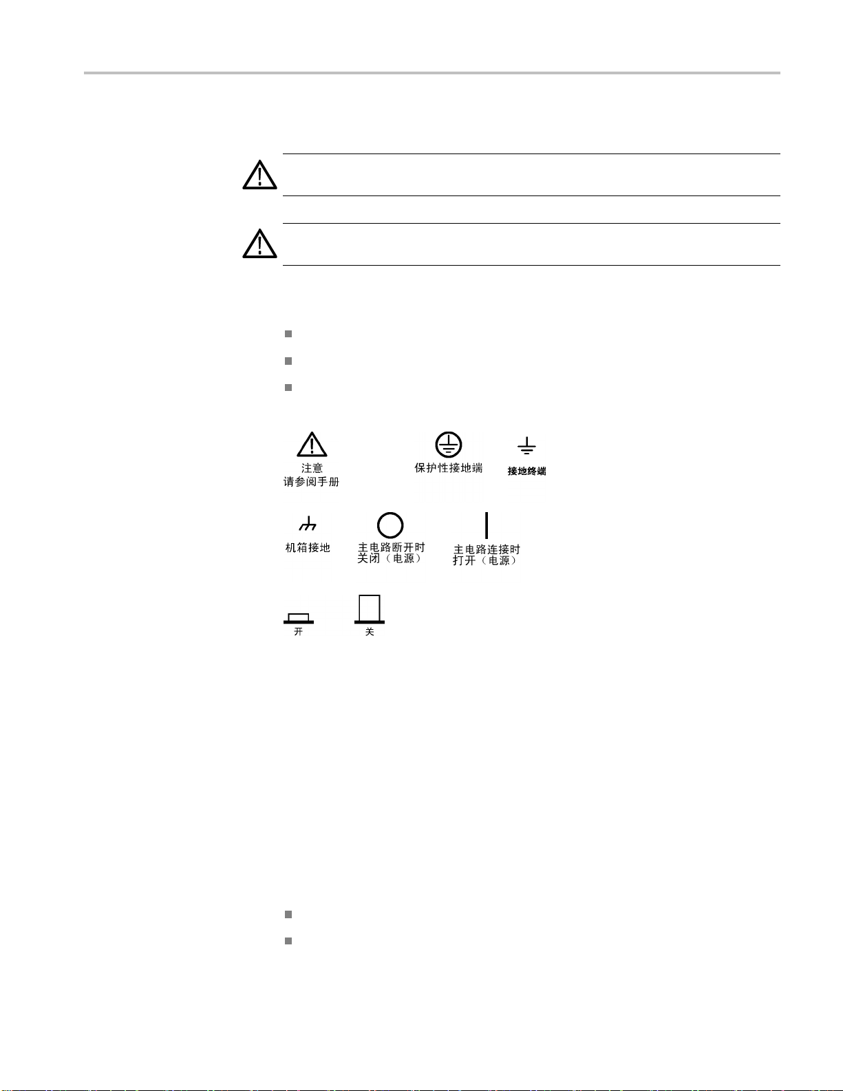
符合性信息
本手册中的术语
产品上的符号和术语
本手册中可能出现以下术语:
警告: “警告”声明指出可能会造成人身伤害或危及生命安全的情况或
操作。
注意: “注意”声明指出可能对本产品或其他财产造成损坏的情况或操
作。
产品上可能出现以下术语:
“危险”表示当您阅读该标记时会立即发生的伤害。
“警告”表示当您阅读该标记时不会立即发生的伤害。
“注意”表示可能会对本产品或其他财产带来的危险。
产品上可能出现以下符号:
符合性信息
此部分列出仪器符合的 EMC(电磁兼容性)、安全和环境标准。
EMC 符合性
EC 符合性声明 - EMC
TBS1000 Series Oscilloscopes Installation and Safety Manual 83
符合 2004/108/EC 指令有关电磁兼容性的要求。已证明符合《欧洲共同体
公报》中所列的以下技术规范:
EN 61326-1:2006, EN 61326-2-1:2006: 测量、控制和实验室用电气设备
的 EMC 要求。
CISPR 11:2003。 放射和传导发射量,1 组,A 类
IEC 61000-4-2:2001。 静电放电抗扰性
123

符合性信息
IEC 61000-4-3:
2002。 射频电磁场抗扰性
4
IEC 61000-4-4:2004。 电气快速瞬变/脉冲抗扰性
IEC 61000-4-5:2001。 电线浪涌抗扰性
IEC 61000-4-6:2003。 传导射频抗扰性
IEC 61000-4-11:2004。 电压暂降和中断抗扰性
5
6
EN 61000-3-2:2006: 交流电源线谐波发射量
EN 61000-3
-3:1995: 电压变化、波动和闪变
欧洲联系方式:
Tektronix UK, Ltd.
Western Peninsula
Western Road
Brackn
ell, RG12 1RF
United Kingdom(英国)
1
本产品仅用于
2
当该设备与测试对象连接时,可能产生超过此标准规定级别的发射量。
3
为确保符合这是列出的各项 EMC 标准,请使用高质量的屏蔽接口电缆。
4
当仪器受到 IEC 61000-4-3 规范的辐射干扰时会出现 ≤ 1.0 标度的波形位移以及 ≤ 2.0 分
度的峰-峰值噪声增加。
5
当仪器受到 IEC 61000-4-3 规范的传导干扰时会出现 ≤ 0.5 标度的波形位移以及 ≤ 1.0 分
度的峰-峰值噪声增加。
6
性能标准 C 适用于 70%/25 循环电压暂降以及 0%/250 循环电压中断测试级别
(IEC61000-4-11)。如果仪器在电压跌落或中断时断电,将需要十秒钟以上的时间才能
返回到以前的工作状态。
非住宅区。在住宅区使用可能引起电磁干扰。
澳大利亚/
新西兰符合性
声明 - EMC
根据 ACMA,符合 Radiocommunications Act(无线电通信法)有关 EMC 规
定的以下标准:
CISPR 11:2003。 放射和传导发射量,1 组,A 类,依照
EN 61326-1:2006 和 EN 61326-2-1:2006。
安全符
EC 符合声明 - 低电压
合性
经证明符合《欧洲共同体官方公报》中所列的以下技术规格:
低电压指令 2006/95/EC。
84 TBS1000 Series Oscilloscopes Installation and Safety Manual

符合性信息
美国国家认可的测试实
验室列表
加拿大证书
其他符合性
设备类型
安全级别
污染度说明
EN 61010-1:200
求。
UL 61010-1:2004,第 2版。 电气测量和测试设备的标准。
CAN/CSA-C22.2 No. 61010-1:2004。对用于测量、控制和实验室的电
气设备的安全性要求。第 1 部分。
IEC 61010-1:2001。 对用于测量、控制和实验室的电气设备的安全
性要求。
测试和测量设备。
1 级 - 接地产品。
测量产品周围和产品内部的环境中可能出现的污染。通常认为产品的内部
环境与外部环境情况相同。仅限在规定环境中使用产品。
1。 对用于测量控制和实验室的电气设备的安全性要
安装(过压)类别说明
过压类别
污染度 1。 无污染或仅出现干燥、非传导性污染。对这种类型的产
品,通常进行封装、密封或将其置于干净的房间中。
污染度 2。通常只发生干燥、非传导性污染。偶尔会发生由凝结引起
的临时传导。典型的办公室/家庭环境属于这种情况。只有不使用产品
时,才会发生临时凝结。
污染度 3。 传导性污染,或由于凝结而使干燥、非传导性污染变为传
导性污染。这些场所建有遮盖设施,温度或湿度不受控制。此类区域
不会直接接触阳光、雨水或自然风。
污染度 4。通过传导性的尘埃、雨水或雪产生永久的传导性污染。户
外场所通常属于这种情况。
本产品的端子可能有不同的安装(过压)类别指定。安装类别包括:
测量类别 IV。 用于在低压安装电源处进行的测量。
测量类别 III。 用于在建筑安装中进行的测量。
测量类别 II。 用于在与低压安装直接相连的电路上进行的测量。
测量类别 I。 用于在未直接连接到干线的电路上进行的测量。
过压类别 II(如 IEC 61010-1 定义)
TBS1000 Series Oscilloscopes Installation and Safety Manual 85

符合性信息
环境注意事项
本部分提供有关产品对环境影响的信息。
产品报废处理
有害物质限制
回收仪器或元件时,请遵守下面的规程:
设备回收: 生产本设备需要提取和使用自然资源。如果对本产品的报废处
理不当,则该设备中包含的某些物质可能会对环境或人体健康造成伤害。
为避免将有害物质释放
当的方法回收本产品,以确保大部分材料可以正确地重复使用或回收。
此符号表示按照 Directives 2002/96/EC 和 2006/66/EC,该产品
符合欧盟对废旧电子电气设备 (WEEE) 和电池的适用法规。有关
回收选件的信息,请查看 Tektronix 网站 (www.tektronix.com)
上的 Support/Service(支持/服务)部分。
本产品归类于工业监视和控制仪器,不需要遵守改版 RoHS 指令 2011/65/EU
(截至 2017 年 7 月 22 日)中的物质限制。
到环境中,并减少对自然资源的使用,建议采用适
86 TBS1000 Series Oscilloscopes Installation and Safety Manual
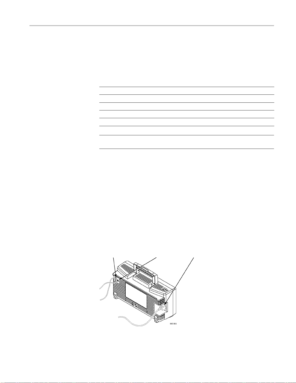
入门
入门
TBS1000 系列数字存储示波器是小型、轻便的台式仪器,可以进行以地为
参考的测量。
型号 通道 带宽 取样速率 显示器
TBS1022 2 25 MHz
TBS1042 2 40 MHz
TBS1062 2 60 MHz
TBS1102 2 100 MHz
TBS1152 2 150 MHz
500 MS/s
500 MS/s
1 GS/s
1 GS/s
1 GS/s
彩色
彩色
彩色
彩色
彩色
说明: 打开示波器电源时,可以选择一种屏幕显示语言。任何时候按下
Utility(辅助功能) ► Language(语言)选项,即可选择一种语言。
安装
电源线
电源
安全带
只能使用随示波器一同提供的电源线。 附录 B: 附件列出标准附件和可
选附件。
请使用电压为 90 到 264 VAC
使用频率为
400 Hz 的电压,则其电压必须为 90 到 132 VAC
且频率为 45 到 66 Hz 的电源。 如果
RMS
,频率为
RMS
360 到 440 Hz。
请使用标
准的笔记本计算机安全锁,或将安全电缆穿过内置的电缆槽来固
定示波器。
安全电缆槽 安全锁孔 电源线
TBS1000 Series Oscilloscopes Installation and Safety Manual 87

入门
通风
功能检查
说明: 示波器通过对流冷却。
在产品的两端以及顶部要留出 2 英寸的
空间以便使空气流通顺畅。
执行此功能检查来验证示波器是否正常工作。
“打开/关闭”按钮
1. 打开示波器电源。
按下 Default Setup(默认设置)按钮。
探头选项默认的衰减设置为 10X。
Default Setup (默认设置)按
钮
探头补偿
2. 将 TPP0101/TP0201 探头连接到示波器上
的通道 1。要进行此操作,请将探头连接
器上的插槽对准 CH 1 BNC 上的凸键,按
下即可连接,然后向右转动将探头锁定到
位。
将探头端部和基准导线连接到“探头补
偿”终端上。
探头安全性
3. 按下“自动设置”按钮。几秒钟后,可看
到显示一条约 5 V 峰-峰值的 1 kHz 方
波。
按两次前面板 1 通道 1 菜单按钮删除
通道 1,按 2 通道 2 菜单按钮显示通
道 2,重复步骤 2 和 3。
使用探头之前,请查看并遵守探头的额定值。
TPP0101/TPP0201 探头本体周围的防护装置可保护手指免受电击。
88 TBS1000 Series Oscilloscopes Installation and Safety Manual

电压探头检查向导
入门
手指防护装置
警告: 要在使用探头时避免电击,应使手指保持在探头主体上防护装置
的后面。
要在使用探头时避免电击,在探头连接到电压电源时不可接触探头顶部的
金属部分。
进行任何测量前,将探头连接到示波器并将接地端接地。
可以使用探头检查向导来验证电压探头是否操作正常。 该向导不支持电
流探头。
该向导帮助调节电压探头的补偿(通常使用探头本体或探头连接器上的
螺丝),设置每个通道“衰减”选项的系数,例如通过 1 ► “探头” ►
“电压” ► “衰减”选项。
每次将电压探头连接到输入通道时,都应该使用探头检查向导。
要使用探头检查向导,请按下 PROBE CHECK(探头检测)按钮。如果电压
探头连接正确、补偿正确,而且示波器“垂直”菜单中的“衰减”选项设
置与探头相匹配,则示波器就会在屏幕的底部显示一条“合格”信息。否
则,示波器会在屏幕上显示一些指示,指导纠正这些问题。
说明: 探头检查向导适用于 1X、10X、20X、50X 和 100X 探头。不适用
00X 和 1000X 探头,也不适用于连接到 Ext Trig(外部触发)BNC
于5
的探头。
说明: 该过程完成之后,探头检查向导将示波器设置恢复到您按下 PROBE
CHECK(探头检测)按钮之前的设置(“探头”选项除外)。
TBS1000 Series Oscilloscopes Installation and Safety Manual 89

入门
手动探头补偿
要对计划使用 Ext Trig
(外部触发)输入的探头进行补偿,请执行以下
步骤:
1. 将探头连接到任何输入通道
BNC,例如通道 1。
2. 按下 PROBE CHECK(探头检测)按钮并遵照屏幕上的指示进行操作。
3. 正确验证探头功能并正确补偿之后,将探头连接到 Ext Trig(外部触
发)BNC。
作为探头检查向导的替代方法,您可以手动执行此调整来匹配探头和输入
通道。
探头补偿
自动设置按
钮
1. 按下 1 ► “探头” ► “电压”
► “衰减”选项并选择 10X 。将
TPP0101/TPP0201 探头连接到示波器上
的通道 1。如果使用探头钩式端部,请
确保钩式端部牢固地插在探头上。
2. 将探头端部连接到 PROBE COMP ~5V@1kHz
(探头补偿 ~5V@1kHz)端子上,将基准
引线连接到 PROBE COMP(探头补偿)机
箱端子上。显示通道,然后按下“自动
设置”按钮。
3. 检查所显示波形的形状。
过补偿
补偿不足
补偿正确
4. 如有必要,请调整探头。
必要时
重复操作。
90 TBS1000 Series Oscilloscopes Installation and Safety Manual

探头衰减设置
入门
探头有不同的衰减系数,它影响信号的垂直刻度。 探头检查向导验证示
波器的衰减系数是否与探头匹配。
作为探头检查的替代方法,可以手动选择与探头衰减相匹配的系数。例
如,要与连接到 CH1 的设置为 10X 的探头相匹配,请按下 1 ► “探头”
► “电压” ► “衰减”选项,然后选择 10X。
说明: “衰减”选项的默认设置为 10X。
如果更改 P2220 探头上的“衰减”开关,则还必须更改示波器“衰减”
选项来与之匹配。
开关设置为 1X 和 10X。
“衰减”开关
电流探头
自校正
标度
说明: 当“
到 6 MHz。 要使用示波器的全带宽,请确保将开关设定到 10X。
电流探头提供与电流成比例的电压信号。 您需要设置示波器来匹配电流
探头的比例。 默认的刻度是 10 A/V。
例如,要设置连接到 CH1 的电流探头的比例,请按下 1 ► “探头” ►
“电流” ► “比例”选项,然后选择一个适当的值。
自校正程序可以以最大测量精度优化示波器信号路径。 您可以随时运行
程序,但当环境温度变化达 5℃ (9℉) 或以上时,应始终运行该程序。
该
此过程大概需要两分钟。
为了校准更精确,请打开示波器电源,然后等待 20 分钟以确保示波器预
热。
要补偿信号路径,请断开输入连接器上连接的任何探头或电缆。然后,访
问 Utility(辅助功能) ► “自校正”选项,并遵照屏幕上的指示进行
操作。
衰减”开关设置为 1X 时,P2220 探头将示波器的带宽限制
TBS1000 Series Oscilloscopes Installation and Safety Manual 91

入门
通过 Internet 更新固件
如果有可用的固件新版本,则可以使用 Internet 和 USB 闪存驱动器更
新示波器。如果不能访问 Internet,请联系 Tektronix 以获得更新过程
所需信息。
要通过 Internet 更新固件,请按照以下步骤执行操作:
1. 按下 Utility(辅助功能) ► “系统状态”选项,然后记下示波器固
2. 通过计算机访问 www.tektronix.com 网站,检查是否有可用的示波器
3. 如果有固件新版本,请从该网页下载固件文件。
件版本号。
固件新版本。
可能需要解压下载的文件。
4. 将固件文件复制
5. 将 USB 闪存驱动器插入示波器前端的 USB 闪存驱动器端口。
6. 按下示波器的 Utility(辅助功能) ► “文件功能” ► “- 更多 2/2 页” ► “更新固件”选项按钮。
更新固件可能需要几分钟时间。
固件更新完成时,示波器将提示您按下按钮。固件更新完成之前,不得拔
出 USB 闪存驱动器,或关闭示波器电源。
到 USB 闪存驱动器的根文件夹。
92 TBS1000 Series Oscilloscopes Installation and Safety Manual
 Loading...