

Page 1
TBS1000C
Demonstration Guide
26 JUNE 2020 - VERSION 1.0
Page 2

26 JUNE 2020 - VERSION 1.0 2
• TBS1000C Oscilloscope Specification and Feature Highlights
• About this demo guide
• Before Starting a Demonstration
• Front Panel Overview
• Getting Acquainted with the User Interface
• Demo Exercise
◦ Before You Start
◦ About Help Everywhere
◦ Using the Scope Intro Built-in Handbook
◦ Using Autoset to Setup the Oscilloscope
◦ Setting up the Trigger for Data Capture
◦ Using Pan and Zoom for more Details
◦ Making Delta Measurement using Cursors
◦ Using Built-in Automatic Measurements
◦ Using FFT for Spectrum Analysis
◦ Exporting Data – Screenshots, Waveform or Setup
◦ Remote Control Interface
Table of Content
Page 3
26 JUNE 2020 - VERSION 1.0 3
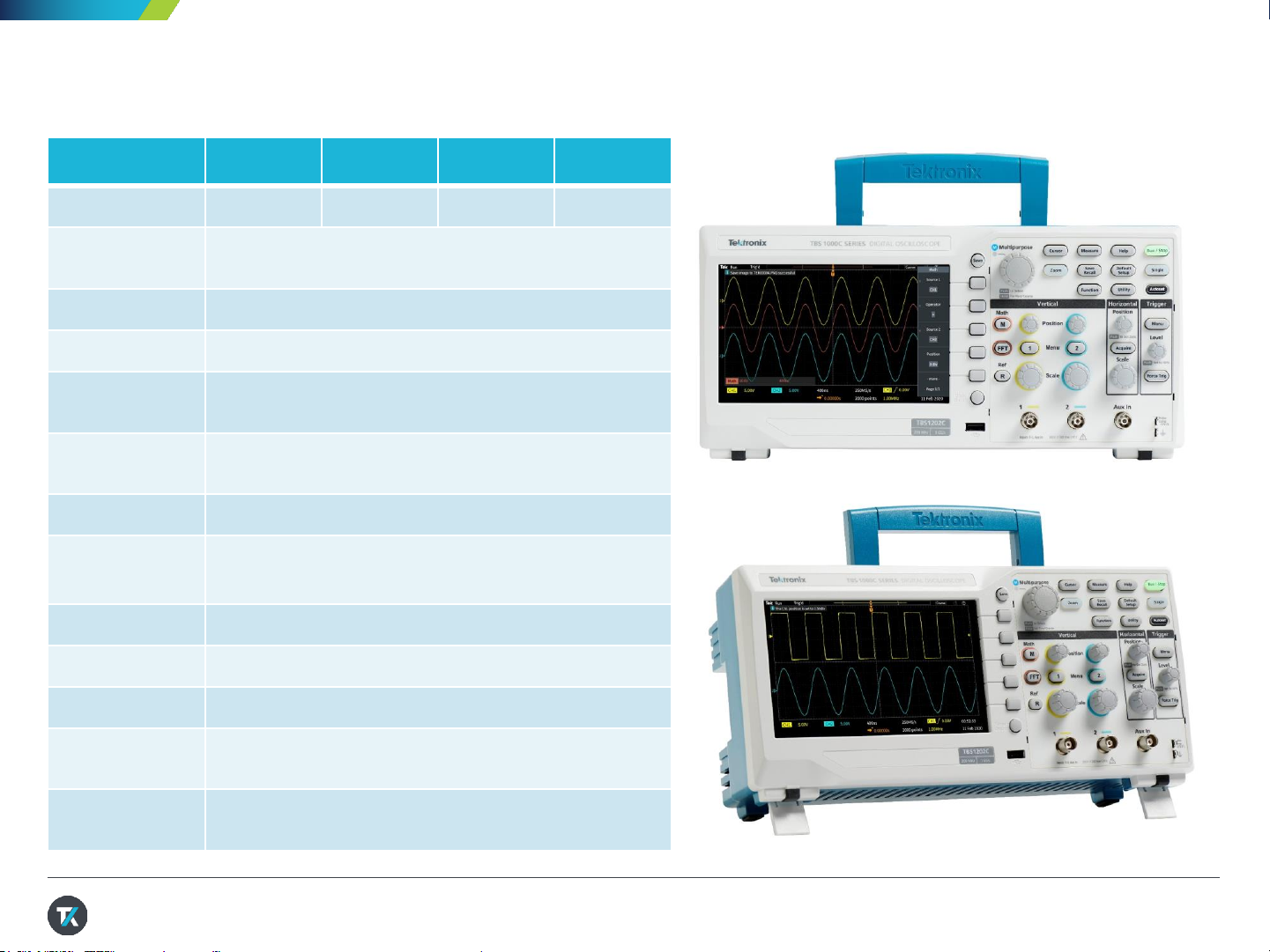
TBS1000C Specification and Feature Highlights
TBS1052C TBS1072C TBS1102C TBS1202C
Bandwidth 50 MHz 70 MHz 100 MHz 200 MHz
Analog Channels 2
Sample Rate 1GS/s (All)
Record Length 20k points
Vertical
Resolution
8 Bit, 1mV/div to 10V/div
Probe Interface Passive BNC probes, Current and Power probes
Trigger Edge, Pulse Width, Runt
Analysis 32 Automated Measurements, Math, Ref, Cursors, FFT,
Zoom, Autoset
Display Size 7 in WVGA
I/O USB Host, USB Device, Aux In
Security Kensington Lock
Software Courseware, OpenChoice Desktop, TekBench
Warranty 5 years
Page 4
26 JUNE 2020 - VERSION 1.0 4
In order to perform the demo procedure, you will need
the following equipment and accessories:
• TBS1000C series oscilloscope
• The passive voltage probes (TPP0100 or
TPP0200) that come with the unit
• Power cord
• USB flash drive (for data export exercise)
• External PC with VISA software installed (for
remote control exercise) – for the latest TekVISA,
please search by the keyword TekVISA on
www.tek.com
About This Guide
Begin by exploring the controls and display of
the TBS1000C Series.Then move on to a
series of hands-on exercises.Acquire
waveforms, learn about triggering, take
measurements,and learn how to save data. Get
an introductionto the TBS1000C’sconnectivity
and remote control capabilities, and tools for
education.
Page 5

26 JUNE 2020 - VERSION 1.0 5
• Power up the instrument
1. Plug in the power cord of your region
2. Press the button to turn on the instrument. Allows the instrument to complete the
power on self tests
3. Connect probes to the channel inputs
• Check on firmware version – it is recommended to get the latest
firmware for the instrument to optimize the product performance.
1. Press Utility button
2. Select Config
3. Using the Multipurpose knob to highlight System Status and press the
Multipurpose knob to enter System Status menu
4. Review the firmware version. Visit www.tek.com for the latest firmware
Before Starting a Demonstration
Page 6

26 JUNE 2020 - VERSION 1.0 6
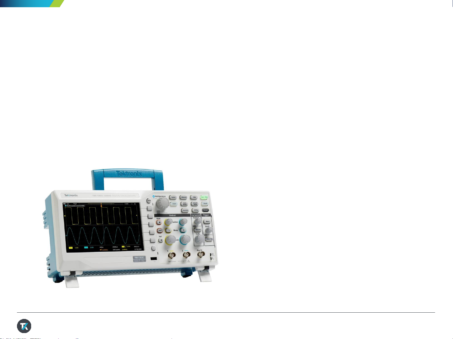
Front Panel Overview
One Touch
Save
USB host port for
flash drive support
Help Everywhere
and Scope Intro
Power button
on the top of
the unit
Probe compensation output
7 inches WVGA display
Menu On/Off
Multipurpose knob
for waveform
navigation and
oscilloscope setup
Page 7
26 JUNE 2020 - VERSION 1.0 7
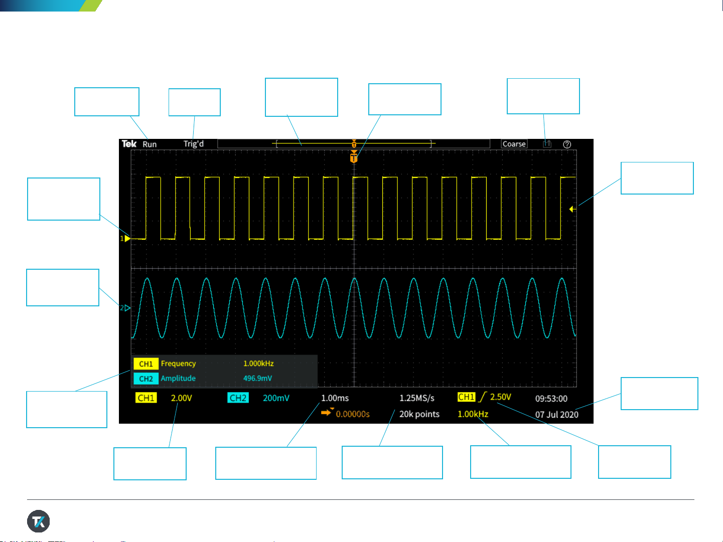
Getting Acquainted with the User Interface
Acquisition
Status
Trigger
Status
Waveform
Record
View
Trigger
Indicator
Active
Channel
Indicator
Channel
Indicator
Auto
Measurement
Display
Vertical
Scale
Horizontal Scale
and Trigger Delay
Sample Rate
and Record Length
Time and Date
Data Transfer
In Progress
Trigger level
Indicator
Frequency Counter Trigger
Source/Level
Page 8
26 JUNE 2020 - VERSION 1.0 8
• User calibration – Signal Path Compensation
(SPC) is designed to correct any DC inaccuracy in
the system due to temperature changes or long
term drift
1. Disconnect any probes or cables from the channel
inputs and Aux in
2. Make sure to warn up the instrument for around 15
to 20 minutes before to running SPC.
3. Press Utility button
4. Select Calibration & Diagnostics
5. Using the Multipurpose knob to select for Signal
Path
6. Press the bezel button next to Compensate Signal
Paths to initialize the SPC
Note: SPC can take up to 20 minutes to run.
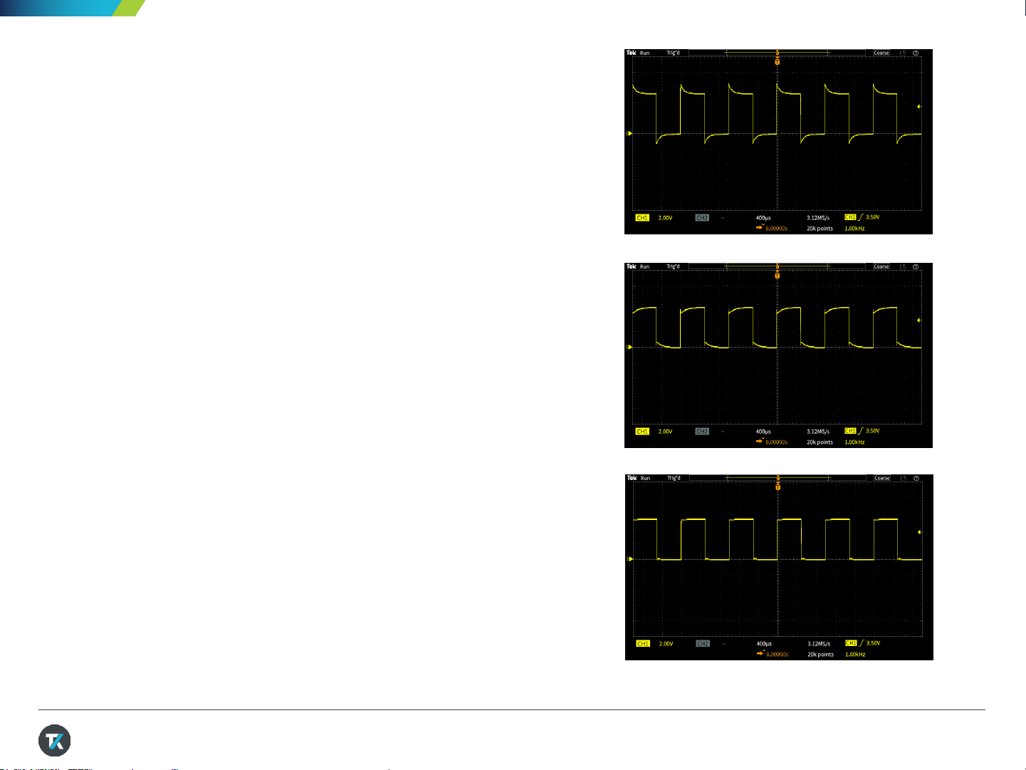
• Compensate the passive voltage probe
1. Connect the passive probe (TPP0100 or TPP0200)
to ch1/ch2 and the probe compensation output
2. Press Autoset button to auto scale the signal on
display
3. Use the compensation adjustment tool that comes
with the probe to adjust any overshoot or undershoot
of the probe compensation signal until you see a
perfect square wave
Before You Start
Probe compensation with undershoot
Probe compensation signal with overshoot
Probe compensation signal after
compensation adjustment
Page 9

26 JUNE 2020 - VERSION 1.0 9
• Enabling Help Everywhere
1. Press Help button on the front panel
2. Select Help Everywhere from the bezel button
(Figure 1)
3. Select on specific topic or all using the
Multipurpose Knob (MPK)
4. When you use the Trigger, Measure,
or Cursor function later on, you’ll see
Help Everywhere tips that explain trigger
modes, measurements, and cursor types
(Figure 2)
About Help Everywhere
While you’re learning your way around the
scope, Help Everyw here provides helpful
tips. Once you become proficient,you can
turn the tips off if you wish.
Figure 1. Enabling Help Everywhere
Figure 2. Helpful tip to provide more details
regarding the FFT window
Page 10
26 JUNE 2020 - VERSION 1.0 10
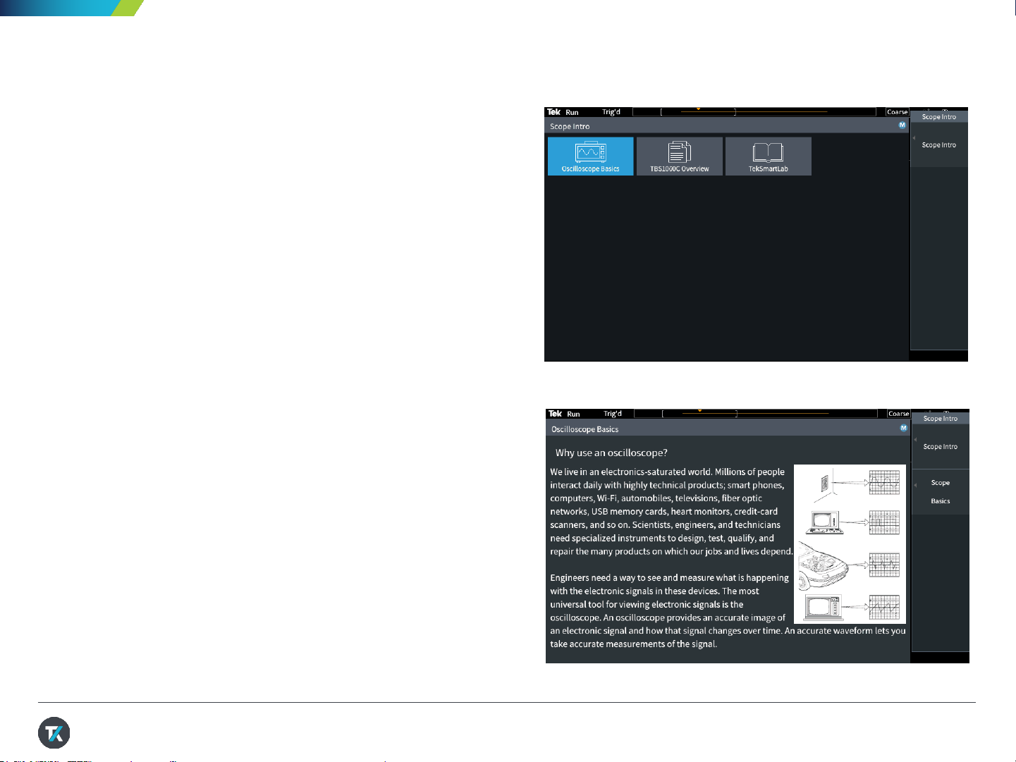
1. Press Help button on the front panel
2. Press Scope Intro bezel button (Figure 3)
3. Select Oscilloscope Basic with the
Multipurpose Knob (MPK)
4. Select Why use an oscilloscope
5. Use the MPK to scroll through the content
(Figure 4)
6. Press Scope Intro again to go back to the top
menu, and explore the other topics. TBS1000C
Overview gives good explanation of the
instrument’s controls and menus.
7. Press Menu On/Off to exit Scope Intro when you
are finished exploring.
Using the Scope Intro Built- in Handbook
If you get stuck, or want to know more about a
particular control, Scope Intro provides a built-in,
handy reference.
Figure 3. Selecting Oscilloscope Basics
Figure 4. Using MPK to scroll through the content
Page 11

26 JUNE 2020 - VERSION 1.0 11
1. Attach the TPP0100 or TPP0200 probe to
the Channel 1 input.
2. Connect the probe’s hook tip to the Probe
Comp output. Clip the ground clip to the
Probe Comp ground terminal.
3. Press Default Setup to recall the factory
default setup.
4. Press Autoset button to auto scale the
signal on screen similar to the Figure 5.
Using Autoset to Acquire a Waveform
Figure 5. Probe Comp Signal display after Autoset
• Autoset is a common feature on the oscilloscope to assist the user to setup the unit for capture.
• Autoset is designed to auto scale the incoming signal around 80% of the display area. That allows the user
to view the signal and avoid clipping.
• After the user is able to view the signal on the screen, it will be easier to adjust the vertical scale to optimize
the digitizer for the most accurate result.
Page 12

26 JUNE 2020 - VERSION 1.0 12
• Real time oscilloscope is a trigger machine. Setting up the trigger
is important to capture the signal/event of your interest.
• On the TBS1000C, it offers three different trigger types: Edge,
Pulse Width or Runt.
Setting up the Trigger for Data Capture
Page 13

26 JUNE 2020 - VERSION 1.0 13
1. Keep Channel 1 connected to Probe Comp output.
2. Press Default Setup.
3. Adjust Vertical Scale on Channel 1 to 2.00V.
4. The default trigger type is Edge with a rising slope.
The default level is 0V. This is shown in yellow in the
lower right of the display.
5. Adjust the Trigger Level toward the center of the
waveform. The trigger level indicator appears during
the adjustment.
6. Press Menu in the Trigger section. Press the Type
side-bezel button (Figure 6). Note that the LED next to
the multipurpose knob (MPK) is lighted, prompting for
a selection.
7. Scroll the MPK to highlight the Pulse Width trigger
type, and press the MPK to select it.
Setting up the Pulse Width Trigger 1/2
Autoset exercise automatically uses Edge trigger. The following exercise will be
using Pulse Width trigger as demonstration purposes..
Figure 6. Trigger selection using MPK to select
Page 14

26 JUNE 2020 - VERSION 1.0 14
8. Note that the Source is CH1 and the Polarity is
Positive.
9. Press – more – Page 1/2 for more selection.
10. Press Trigger When, and use the MPK to select
Pulse Width >. Change the pulse duration to >
10ns. Since the pulse width is much greater than
10 ns, the waveform triggers (Figure 7).
11. Press Menu On/Off button below the display to
exit the menu.
Setting up the Pulse Width Trigger 2/2
Figure 7. Setting pulse width trigger parameters
Page 15

26 JUNE 2020 - VERSION 1.0 15
1. Press the Acquire button on the front panel. Notice
that the Multipurpose Knob LED is on, which
means it can be used to make a selection.
2. Set Record Length to 20K by turning the
Multipurpose Knob (MPK) and press the knob
to make the selection.
3. Change the horizontal scale to 10ms/div with the
Horizontal Scale knob.
4. Press the Zoom button. The button lights to show
that Zoom is active.
5. Turn the MPK to change the zoom scale factor
from 1X to 100X. See the details of the trigger
edge (Figure 8).
Using Pan and Zoom 1/2
Sometime it is nice to view the whole waveform without trading off the details.
The zoom feature allows the user to look into the details for the long record
Figure 8. 100x zoom in
Page 16

26 JUNE 2020 - VERSION 1.0 16
6. Set the zoom factor back to 100X. Press the
Position bezel button. Turn the MPK to position a
falling edge in the center of the zoom area.
7. Adjust the Horizontal Scale knob to 200us, and
use the MPK to zoom in on the falling edge detail.
Adjust position if needed (Figure 9).
Using Pan and Zoom 2/2
Figure 9. Zoom in details on the failing edge
Page 17

26 JUNE 2020 - VERSION 1.0 17
1. Press Default Setup. Press Autoset.
2. Press the Cursor button beside the MPK
(Figure 10).
3. Press the Screen bezel button to select
independent control of both amplitude and time
cursors.
4. Turn the MPK to move the left time cursor close to
the position you would like to measure.
5. To position the cursor more precisely, press and
hold the MPK to select the Fine scale. Now turn
the MPK to left cursor exactly on a rising edge of
the signal.
6. Press the MPK to change control to the right
time cursor. Turn the MPK and use Fine to
position the cursor on the next rising edge.
Making Delta Measurement using Cursors
1/2
Cursors is the flexible measurement tool to assist user to make any delta time or delta amplitude
measurement
Figure 10. Cursor button next to
the multipurpose knob (MPK)
Page 18

26 JUNE 2020 - VERSION 1.0 18
7. Note the delta time readout between the cursors
and the time position for each bar.
8. Press MPK again to change control to the upper
cursor for amplitude measurements. Move the
cursor to the top of the signal and note the delta
readout (Figure 11).
In the next section, you’ll use automated
measurements to get similar results.
Making Delta Measurement using Cursors
2/2
Figure 11. Using cursors to measure period and
amplitude of the probe comp. signal
Page 19

26 JUNE 2020 - VERSION 1.0 19
1. Connect passive probes to Channel 1 and
Channel 2. Connect both probe tips to Probe
Comp and both ground clips to Probe Comp
ground.
2. Press Autoset.
3. Press the Measure button in the resource section
of the front panel.
4. Notice, from top to bottom(Figure 12):
Using Built-in Automatic Measurements 1/2
Automated measurementsuse the processing power of the
scope to provide a frequency, time, amplitude, and area
measurements.
Figure 12. Auto Measurement selection menu
• Measurement selection indicator bar
• Snapshot button
• Most Used measurement list
• Measurements grouped by Frequency, Time,
Amplitude,Area
Page 20

26 JUNE 2020 - VERSION 1.0 20
5. Press the CH1 bezel button. Scroll and press
MPK to select Frequency and +Duty for Channel
1.
6. Press the CH2 bezel button. Scroll and press
MPK to select Peak-Peak and Mean for Channel
2. (Figure 13)
7. Press Menu On/Off to return to the waveform
window.
8. Note the measurement readout (Figure 14).
9. Press Menu On/Off a couple of times to hide and
recall the measurement readout panel .
Using Built-in Automatic Measurements 2/2
Figure 13. Adding Auto Measurement for Ch1 and Ch2
Figure 14. Transparent readouts let the signal show through
Page 21

26 JUNE 2020 - VERSION 1.0 21
1. Keep the TPP0100 passive probe connected to
Channel 1 and the Probe Comp output.
2. Press Default Setup. Press Autoset.
3. Press the FFT button for FFT function on the front
panel (Figure 15).
4. By default, the source waveform is on. Turn it off by
pressing the Source wfm bezel button.
5. Source Channel, Vertical Units, WindowType ,
Horizontal Center Position and Scale may be adjusted
by selecting the corresponding bezel button and
adjusting with the MPK .
6. The FFT readout panel in the top right corner of the
waveform display shows important settings.
7. The default FFT window is Hanning. Use the Window
bezel button and MPK to switch to the Rectangular
window and note the result.
Using FFT for Spectrum Analysis 1/2
Figure15. FFT Menu
The FFT function calculates the frequencyinput of the source waveform.
Cursors make it easy to measure frequencyand amplitude in the spectrum.
Page 22

26 JUNE 2020 - VERSION 1.0 22
8. The default FFT window is Hanning. Use the
Window bezel button and MPK to switch to the
Rectangular window and note the result.
9. Press the Horizontal Scale bezel button and use
the MPK to adjust the horizontal scale to 1.56
kHz/div.
10. Press the Cursor button and position the cursors
on the third and fifth harmonic frequencies
(Figure 16).
11. The delta between third harmonic and fifth
harmonic frequency should be 2 kHz, which is
consistent with the 1 kHz fundamental frequency
of the Probe Comp output.
Using FFT for Spectrum Analysis 2/2
Figure 16. Delta frequency between the 3rd and the
5thharmonic is around 2kHz
Page 23

26 JUNE 2020 - VERSION 1.0 23
1. Press Default Setup. Press Autoset.
2. Plug a USB flash drive into the USB host port on
the oscilloscope’s front panel.
3. Press Save/Recall in the Resource section of the
front panel.
4. Use the side bezel button to set the Action to
Save Image. (Figure 17)
5. Set the Save As to JPG.
6. You could also assign to save image every time
when pressing the Save/Print button.
7. Press Save/Recall button. Select Settings.
Press the bezel button next to the Assign Save
Button To Image.
8. Press the bezel button next to Change Folder and
then press New Folder. Use the MPK to set up a
new folder named “DEMO” .
Exporting Data – Saving Screen Image 1/2
TBS1000C series allows user to export data to a USB flash drive or via the USB device port to a computer.
The data that could be exported include the screen image, setup or waveform.
Figure 17. Selecting to save as Image
Page 24

26 JUNE 2020 - VERSION 1.0 24
8. Press Back.
9. Highlight and select the new DEMO folder with the
MPK.
10. Press the Save button outside the right top corner
of the display(Figure 18) to save an image into the
DEMO GUIDE folder on the USB thumb. The hint
line should say that the image was successfully
saved(Figure 18).
11. Take the flash drive to a PC equipped with a USB
host port. You can now open the screenshot image
as you would to any image file.
Exporting Data – Saving Screen Image 2/2
Figure 18. Save button next to the MPK
Page 25

26 JUNE 2020 - VERSION 1.0 25
1. Make sure you have the VISA software installed on
the remote PC.
2. To download TekVISA, please go to www.tek.com
and search for keyword “TekVISA” (Figure 19).
NI-VISA is also compatible with the TBS1000C if
you prefer to use NI-VISA.
3. The VISA software provides the USBTMC (USB
Test and Measurement Class) device driver for the
PC to recognize the TBS1000C oscilloscope.
4. After the VISA software is installed, connect the
TBS1000C scope to the PC using the USB device
port on the rear panel.
5. If you are having issue to detect the scope on the
PC, please check in the device manager and see if
the USB driver is installed correctly. If not, try
manually install the driver by going to the Driver
tab to Update Driver.
Note. If the driver is installed correctly, it listed as USB
Test and Measurement Device (IVI) (Figure 20)
Remote Control Interface 1/2
TBS1000C equipped with USB device port on the rear panel for PC connectivity.
It is using USBTMC with VISA software for communication. The following exercise step you through
the setup for remote control
Figure 19. Search for TekVISA from www.tek.com
Figure 20. USB device listed in the device manager
Page 26

26 JUNE 2020 - VERSION 1.0 26
6. To confirm the connectivity, right click on TekVISA
icon (Figure 21) and bring up the Instrument
Manager…
7. The TBS1000C will be listed in the Instruments list
(Figure 22)
8. Double click on OpenChoice Talker Listener to
bring the command prompt
9. Try with the *IDN? Command. If you query the
*IDN? Command, it will return the scope’s serial
number and firmware version. (Figure 23)
10. You could also use the command
“SELECT:CH2 ON” to turn on channel 2 on the
display
Remote Control Interface 2/2
Note: OpenChoice Desktop, TekBench are some of
the optional software to export data from the
TBS1000C to the PC.
Figure 21. Open TekVISA instrument manager
Figure 22. Look for the USB item in the Instrument list
Figure 23. Sending *IDN? In the command prompt
Page 27

The PC Courseware Editor helps you create lab
descriptions and instructions on a PC and then upload
the material directly onto a TBS1000C oscilloscope.
You can modify existing labs with content that directly
supports recent lectures or incorporates ideas
discovered in class discussions. Your students can
perform their lab work directly on the oscilloscope and
can even automatically generate an HTML formatted
lab report for submission and grading directly from the
instrument.
Bonus Demo: Create and load custom
courseware (1/3)
1. After installing an opening PC Courseware Editor
V2.0 on your computer click the Create button
under the Lab section(Figure 24).
2. Next give your lab a name and click OK.
3. Select the lab you just created and select the Edit
button (Figure 25).
Figure 24. Creating a new lab in PC Courseware Editor V2.0
27
Bonus
Demo
Addition equipment needed:
• PC Courseware Editor Tool V2.0
• USB drive
Figure 25. Selecting a lab to edit in PC Courseware Editor V2.0
26 JUNE 2020 - VERSION 1.0
Page 28

The PC Courseware Editor helps you create lab
descriptions and instructions on a PC and then upload
the material directly onto a TBS1000C oscilloscope.
You can modify existing labs with content that directly
supports recent lectures or incorporates ideas
discovered in class discussions. Your students can
perform their lab work directly on the oscilloscope and
can even automatically generate an HTML formatted
lab report for submission and grading directly from the
instrument.
Create and load custom courseware
(2/3)
4. Now use the editor page on the Objective tab to
describe the main objective of the lab. Feel free to
use pictures, graphs, and tables. (Figure 26).
5. Now click on the Procedure tab describe the
main procedure of the lab.
6. Click Save and Quit once finished figure (Figure
27).
Figure 26. Creating a lab objective for students to read before
starting the lab
28
Figure 27. Creating a lab procedure for students to follow
5
6
26 JUNE 2020 - VERSION 1.0
Page 29

Create and load custom
courseware (3/3)
29
Figure 28. Creating a lab objective for students to read before starting the lab
7. Follow the steps in Figure 28 to create
a package that can be loaded on the
TBS1000C
8. Select the package and export it to
a USB thumbdrive.
9. Click Save and Quit once finished
figure (Figure 27).
10. Plug the USB drive into the scope
and press the Utility button.
11. Press the –more – Page ½ and
then Update Course button to
upload the course the instrument
(Figure 29).
12. Confirm that the course is loaded by
pressing the Help button and then
pressing Courses.
Figure 29. Creating a lab objective for students to read before starting
the lab
26 JUNE 2020 - VERSION 1.0
Page 30

26 JUNE 2020 - VERSION 1.0 30
• Education features are now standard to the TBS1000C series.
• Password protected Enable / Disable:
◦ Autoset
◦ Cursors
◦ Measurement
• Enables Educators to teach:
◦ How to operate the instrument
◦ Basic concepts of signal capture and analysis
• Courseware
◦ Easy access to built-in lab exercise
◦ Add additional lab exercises
TBS1000C Education Features
Page 31

Page 32

Find more valuable resources at TEK.COM
Copyright © Tektronix. All rights reserved. Tektronix products are covered by U.S. and foreign patents, issued and pending. Information in this publication supersedes that in all previously published material. Specification and price change privileges
reserved. TEKTRONIX and TEK are registered trademarks of Tektronix, Inc. All other trade names referenced are the service marks, trademarks or registered trademarks of their respective companies.
062620 3GW-61718-0
 Loading...