

Page 1

TBS1000C Series Oscilloscopes
User Manual
*P077157101*
077-1571-01
Page 2

Page 3

TBS1000C Series Oscilloscopes
User Manual
Register now!
Click the following link to protect your product.
www.tek.com/register
077-1571-01
Page 4

Copyright © Tektronix. All rights reserved. Licensed software products are owned by Tektronix or its subsidiaries or suppliers, and are
protected by national copyright laws and international treaty provisions. Tektronix products are covered by U.S. and foreign patents, issued
and pending. Information in this publication supersedes that in all previously published material. Specifications and price change privileges
reserved.
TekVPI and e*Scope are registered trademarks of Tektronix, Inc.
TEKTRONIX and TEK are registered trademarks of Tektronix, Inc.
Contacting Tektronix
Tektronix, Inc.
14150 SW Karl Braun Drive
P.O. Box 500
Beaverton, OR 97077
USA
For product information, sales, service, and technical support:
• In North America, call 1-800-833-9200.
• Worldwide, visit www.tek.com to find contacts in your area.
Page 5

Table of Contents
Table of Contents
List of Figures................................................................................................................................................................................9
List of Tables............................................................................................................................................................................... 10
TEKTRONIX SOFTWARE LICENSE AGREEMENT...................................................................................................................11
Important safety information........................................................................................................................................................15
General safety summary......................................................................................................................................................15
Symbols and terms on the product...................................................................................................................................... 17
Compliance information.............................................................................................................................................................. 19
EMC compliance..................................................................................................................................................................19
Safety compliance................................................................................................................................................................19
Environmental considerations..............................................................................................................................................21
Preface........................................................................................................................................................................................22
Key features.........................................................................................................................................................................22
Conventions used in this manual......................................................................................................................................... 22
Installation................................................................................................................................................................................... 23
Unpacking the Oscilloscope.................................................................................................................................................23
Operating requirements.............................................................................................................................................................. 27
Environment requirements...................................................................................................................................................27
Power requirements.............................................................................................................................................................27
TPP0100, TPP0200 series 10X passive probes information............................................................................................... 27
Connecting the probe to the oscilloscope.....................................................................................................................28
Compensating the probe.............................................................................................................................................. 28
Connecting the probe to the circuit............................................................................................................................... 29
Standard accessories................................................................................................................................................... 29
Optional accessories.................................................................................................................................................... 30
Specifications................................................................................................................................................................30
Performance graphs..................................................................................................................................................... 32
Getting acquainted with the oscilloscope.................................................................................................................................... 34
Powering the oscilloscope................................................................................................................................................... 34
Changing the user interface language................................................................................................................................. 35
Changing the date and time.................................................................................................................................................38
Supported probe types.........................................................................................................................................................41
Reducing electrostatic damage while taking measuremens................................................................................................ 41
Doing a functional check......................................................................................................................................................41
What is Autoset ...................................................................................................................................................................44
Probes and ground leads tip................................................................................................................................................ 44
Getting on-screen help for settings HelpEverywhere™..................................................................................................... 45
Signal path compensation SPC........................................................................................................................................... 47
The Scope Intro function......................................................................................................................................................48
Sampling oscilloscope concepts................................................................................................................................................. 50
Sampling and acquisition concepts......................................................................................................................................50
Acquisition mode concepts.................................................................................................................................................. 50
Trigger concepts.................................................................................................................................................................. 51
Trigger slope and level concepts......................................................................................................................................... 52
Available trigger types..........................................................................................................................................................53
TBS1000C Series Oscilloscopes User Manual 5
Page 6

Table of Contents
Trigger coupling................................................................................................................................................................... 53
Trigger modes......................................................................................................................................................................54
Auto Untriggered Roll trigger mode..................................................................................................................................... 54
Normal trigger mode............................................................................................................................................................ 54
Holdoff trigger mode.............................................................................................................................................................54
Trigger delay acquisition mode............................................................................................................................................ 54
Setting channel input parameters............................................................................................................................................... 56
Setting input signal coupling................................................................................................................................................ 56
Inverting the input signal...................................................................................................................................................... 56
Setting the oscilloscope bandwidth......................................................................................................................................57
Setting the probe type voltage or current.............................................................................................................................57
Setting the probe attenuation factor.....................................................................................................................................58
Quickly setting the probe attenuation to 1X or 10X..............................................................................................................58
Setting the measure current mode for voltage probes.........................................................................................................59
Setting the input signal vertical offset...................................................................................................................................59
Setting the waveform vertical position................................................................................................................................. 60
The difference between vertical position and vertical offset.................................................................................................60
Setting channel deskew....................................................................................................................................................... 61
Deskew tips..........................................................................................................................................................................61
Trigger setup............................................................................................................................................................................... 63
Triggering on a waveform edge........................................................................................................................................... 63
Triggering on a specified pulse width...................................................................................................................................64
Triggering on a runt pulse.................................................................................................................................................... 64
Setting the trigger mode.......................................................................................................................................................65
Trigger on an external signal using the AUX input...............................................................................................................66
Acquisition setup......................................................................................................................................................................... 67
Using Autoset.......................................................................................................................................................................67
Autoset tips.......................................................................................................................................................................... 67
How to enable/disable Autoset in the oscilloscope.............................................................................................................. 68
How to change the Autoset password................................................................................................................................. 69
Starting and stopping an acquisition.................................................................................................................................... 70
Setting the acquisition mode................................................................................................................................................71
Setting the acquisition trigger delay time............................................................................................................................. 72
Setting the record length......................................................................................................................................................73
Using the roll display mode..................................................................................................................................................74
Roll mode tips...................................................................................................................................................................... 74
Setting the oscilloscope to factory default values - Default Setup....................................................................................... 75
Waveform display settings.......................................................................................................................................................... 76
Displaying and removing a waveform.................................................................................................................................. 76
Setting the waveform persistence........................................................................................................................................76
Waveform persistence tip.....................................................................................................................................................77
The XY display mode...........................................................................................................................................................77
XY display mode tips........................................................................................................................................................... 79
Setting the backlight intensity.............................................................................................................................................. 79
Analyzing a waveform................................................................................................................................................................. 80
Taking automatic measurements......................................................................................................................................... 80
Automatic measurements tip............................................................................................................................................... 81
Taking a measurement snapshot......................................................................................................................................... 81
Snapshot measurement tip.................................................................................................................................................. 82
TBS1000C Series Oscilloscopes User Manual 6
Page 7

Table of Contents
Automatic measurement descriptions..................................................................................................................................82
Frequency measurement descriptions.................................................................................................................................82
Time measurement descriptions..........................................................................................................................................83
Amplitude measurement descriptions..................................................................................................................................84
Area measurement descriptions.......................................................................................................................................... 86
Taking a measurement on just a part of the waveform Gating.............................................................................................86
How to enable / disable measurement in the oscilloscope.................................................................................................. 87
Using cursors to take manual measurements......................................................................................................................88
Cursor types.........................................................................................................................................................................90
How to enable / disable cursor in the oscilloscope.............................................................................................................. 91
Creating math waveforms.................................................................................................................................................... 92
Math waveform tips..............................................................................................................................................................94
Using FFT to see signal frequency information................................................................................................................... 94
FFT tips................................................................................................................................................................................98
About FFT windows............................................................................................................................................................. 98
FFT and display waveform aliasing................................................................................................................................... 100
Displaying reference waveforms........................................................................................................................................100
Reference waveform tips................................................................................................................................................... 101
How to view long record length waveforms Zoom............................................................................................................. 101
How to pan a waveform..................................................................................................................................................... 102
How to change the measurement password......................................................................................................................103
Saving data............................................................................................................................................................................... 104
Saving screen images to a file........................................................................................................................................... 104
About saved image file formats..........................................................................................................................................104
Saving waveform data....................................................................................................................................................... 105
Saving oscilloscope setup information...............................................................................................................................106
Saving files to USB with the Save File button....................................................................................................................106
About waveform data files..................................................................................................................................................107
Recalling data........................................................................................................................................................................... 108
Recalling oscilloscope setup information........................................................................................................................... 108
Recalling waveform data....................................................................................................................................................108
Using the USB file utility functions.............................................................................................................................................110
Overview of the File Utility pane.........................................................................................................................................110
Changing the default file save location on the USB drive...................................................................................................111
Default save folder location rules....................................................................................................................................... 111
Creating a new folder on the USB drive.............................................................................................................................112
Folder creation tip...............................................................................................................................................................112
Deleting files or folders from the USB drive....................................................................................................................... 112
Renaming files or folders on the USB drive....................................................................................................................... 113
File folder renaming tip.......................................................................................................................................................114
About automatically generated file names......................................................................................................................... 114
Image setting and waveform file tips..................................................................................................................................115
Erasing data from oscilloscope memory (TekSecure)............................................................................................................... 116
Setting or viewing USB Device port parameters....................................................................................................................... 117
Disabling the USB Device port...........................................................................................................................................117
Selecting which device is attached to the USB Device port...............................................................................................117
Viewing the USBTMC information......................................................................................................................................118
Appendices............................................................................................................................................................................... 120
Installing new firmware on the oscilloscope.......................................................................................................................120
TBS1000C Series Oscilloscopes User Manual 7
Page 8

Table of Contents
Running diagnostic tests....................................................................................................................................................121
Courseware on-instrument education and training............................................................................................................ 121
Courseware file content information........................................................................................................................... 122
Loading a courseware file from a USB drive...............................................................................................................122
Dealing with error message........................................................................................................................................ 123
Running Courseware lab exercises............................................................................................................................ 123
Saving Courseware lab results................................................................................................................................... 124
The oscilloscope controls...................................................................................................................................................124
The Navigation controls.............................................................................................................................................. 124
The Horizontal controls...............................................................................................................................................126
The Trigger controls....................................................................................................................................................127
The Vertical controls................................................................................................................................................... 127
Using the menu system.............................................................................................................................................. 128
Front-panel connectors...............................................................................................................................................130
Rear-panel connectors................................................................................................................................................131
The graphical user interface elements...............................................................................................................................131
Labeling channels.......................................................................................................................................................135
Warranted specifications....................................................................................................................................................137
Cleaning.............................................................................................................................................................................137
General care............................................................................................................................................................... 137
Cleaning......................................................................................................................................................................137
The default oscilloscope settings Default Setup................................................................................................................ 138
Oscilloscope settings that are not reset by Default Setup.......................................................................................... 139
Physically securing the oscilloscope..................................................................................................................................139
Environmental considerations............................................................................................................................................140
Product end-of-life handling........................................................................................................................................140
Equipment recycling................................................................................................................................................... 140
Index......................................................................................................................................................................................... 141
TBS1000C Series Oscilloscopes User Manual 8
Page 9

List of Figures
List of Figures
Figure 1: Untriggered display...................................................................................................................................................... 51
Figure 2: Triggered display..........................................................................................................................................................52
TBS1000C Series Oscilloscopes User Manual 9
Page 10

List of Tables
List of Tables
Table 1: Electrical and mechanical specifications....................................................................................................................... 30
Table 2: Electrical and mechanical specifications....................................................................................................................... 31
Table 3: Environmental specifications......................................................................................................................................... 31
Table 4: Certifications and compliances......................................................................................................................................32
Table 5: Roll mode is enabled when:.......................................................................................................................................... 74
Table 6: Frequency measurements.............................................................................................................................................83
Table 7: Time measurements......................................................................................................................................................83
Table 8: Amplitude measurements..............................................................................................................................................85
Table 9: Area measurements...................................................................................................................................................... 86
Table 10: FFT windows............................................................................................................................................................... 99
TBS1000C Series Oscilloscopes User Manual 10
Page 11

TEKTRONIX SOFTWARE LICENSE AGREEMENT
TEKTRONIX SOFTWARE LICENSE AGREEMENT
This End User Agreement (“Agreement”) is an agreement between Tektronix, Inc., an Oregon corporation, and its corporate affiliates,
subsidiaries, and divisions as applicable (collectively, “Tektronix,” “we,” “us,” or “our”) and You (including any entity or organization you
represent, collectively, “Customer” or “You”). Please read this Agreement carefully as this Agreement governs the terms and conditions
under which You are permitted to use Tektronix’s software and services.
THE SOFTWARE, ENCODED OR INCORPORATED WITHIN EQUIPMENT OR ACCOMPANYING THIS AGREEMENT, IS FURNISHED
SUBJECT TO THE TERMS AND CONDITIONS OF THIS AGREEMENT. BY INDICATING YOUR ACCEPTANCE OF THESE TERMS
BY SELECTING AN "ACCEPT” OR SIMILAR BUTTON IN A SOFTWARE MENU, OR BY RETAINING THE SOFTWARE FOR MORE
THAN THIRTY DAYS OR USING THE SOFTWARE IN ANY MANNER YOU (A) ACCEPT THIS AGREEMENT AND AGREE THAT YOU
ARE LEGALLY BOUND BY ITS TERMS; AND (B) REPRESENT AND WARRANT THAT: (I) YOU ARE OF LEGAL AGE TO ENTER
INTO A BINDING AGREEMENT; AND (II) IF YOU ARE A REPRESENTATIVE FOR A CORPORATION OR OTHER LEGAL ENTITY,
YOU HAVE THE RIGHT, POWER, AND AUTHORITY TO ENTER INTO THIS AGREEMENT ON BEHALF OF SUCH ENTITY AND BIND
SUCH ENTITY TO ITS TERMS. IF YOU DO NOT AGREE TO THE TERMS OF THIS AGREEMENT, TEKTRONIX WILL NOT AND DOES
NOT LICENSE THE SOFTWARE TO YOU AND YOU MUST NOT DOWNLOAD, INSTALL, OR USE THE SOFTWARE. UNITED STATES
GOVERNMENT CUSTOMERS OR END-USERS MAY REQUEST A GOVERNMENT ADDENDUM TO THIS AGREEMENT.
NOTWITHSTANDING ANYTHING TO THE CONTRARY IN THIS AGREEMENT OR YOUR ACCEPTANCE OF THE TERMS AND
CONDITIONS OF THIS AGREEMENT, NO LICENSE IS GRANTED (WHETHER EXPRESSLY, BY IMPLICATION, OR OTHERWISE)
UNDER THIS AGREEMENT TO ANY SOFTWARE THAT YOU DID NOT ACQUIRE LAWFULLY OR THAT IS NOT A LEGITIMATE,
AUTHORIZED COPY OF TEKTRONIX’S SOFTWARE. THIS AGREEMENT EXPRESSLY EXCLUDES ANY RIGHTS CONCERNING
SUCH ILLEGITIMATE COPIES.
IF THESE TERMS ARE NOT ACCEPTABLE, THE UNUSED SOFTWARE AND ANY ACCOMPANYING DOCUMENTATION SHOULD BE
RETURNED PROMPTLY TO TEKTRONIX (WITHIN 30 DAYS OF PURCHASE) FOR A FULL REFUND OF THE LICENSE FEE PAID.
(FOR INFORMATION REGARDING THE RETURN OF SOFTWARE ENCODED OR INCORPORATED WITHIN EQUIPMENT, CONTACT
THE NEAREST TEKTRONIX SALES OFFICE.)
DEFINITIONS
“Equipment” means Tektronix equipment that the Software is encoded or incorporated within or installed onto.
LICENSE
Subject to the terms and conditions of this Agreement, Tektronix grants You a non-exclusive, non-transferable license to the Software, as
follows
You may:
1. Use the Software with the Equipment, or if the Software is not encoded or incorporated in any Tektronix equipment, on no more than
one machine at a time; and
2. Copy the Software for archival or backup purposes, provided that no more than one (1) such copy is permitted to exist at any one time,
and provided that each copy includes a reproduction of any patent or copyright notice or restrictive rights legend that was included with
the Software, as received from Tektronix;
3. Fully transfer the Equipment to a third party but only if prominently accompanied by this End User License Agreement, and such
third-party recipients agree to be bound by the terms of this Agreement; and
4. Integrate Tektronix products that contain the Software into a system and sell or distribute that system to third parties, provided that
those third parties are bound by the terms of this Agreement, and provided that You (i) do not separate the Software from any
Equipment it is incorporated into, (ii) do not retain any copies of the Software, and (iii) do not modify the Software.
You may not:
1. Use the Software other than for its intended purpose as provided above in the section “You may,” or in conflict with the terms and
restrictions of this Agreement;
2. Distribute or transfer the Software to any person or organization outside of Your organization without Tektronix’s prior written consent,
except in connection with a permitted use authorized in “You may” paragraphs 3 or 4 above;
TBS1000C Series Oscilloscopes User Manual 11
Page 12

TEKTRONIX SOFTWARE LICENSE AGREEMENT
3. Decompile, decrypt, disassemble, or otherwise attempt to derive the source code, techniques, processes, algorithms, know-how,
or other information (collectively “Reverse Engineer”) from the Software or permit or induce any third party to do so, except to the
limited extent allowed by directly applicable law or third party license (if any), and only to obtain information necessary to achieve
interoperability of independently created software with the Software;
4. Modify, translate, adapt, or create derivative works of the Software, or merge the Software with any other software;
5. Copy the documentation accompanying the Software;
6. Remove any copyright, trademark, or other proprietary notices from the Software or any media relating thereto; or
7. Export or re-export, directly or indirectly, the Software or Equipment, any associated documentation, or systems created in
accordance with “You may” section 4 above, to any country to which such export or re-export is restricted by law or regulation of
the United States or any foreign government having jurisdiction without the prior authorization, if required, of the Office of Export
Administration, Department of Commerce, Washington, D.C. and the corresponding agency of such foreign government;
8. Use the Software or Equipment in any manner or for any purpose that infringes, misappropriates, or otherwise violates any
intellectual property rights or other proprietary rights of any person, or any applicable laws;
9. Use the Software or Equipment in a network or system with other products or services that are incompatible, insecure or not
compliant with applicable laws;
10. Bypass, circumvent, damage or otherwise interfere with any security or other features of the Software or Equipment designed to
control the manner in which they are used, or harvest or mine Tektronix’s proprietary content or information from the Software or
Equipment.
THE SOFTWARE MAY NOT BE USED, COPIED, MODIFIED, MERGED, OR TRANSFERRED TO ANOTHER EXCEPT AS EXPRESSLY
PERMITTED BY THESE TERMS AND CONDITIONS.
FEEDBACK
If You provide feedback to Tektronix concerning the functionality and performance of the Software or Equipment, including without limitation
identifying potential errors and improvements, any comments, questions, suggestions, or the like ("Feedback"), Tektronix is free to use
such Feedback without any attribution, compensation, or restriction in any manner to improve or enhance its products, irrespective of
any other obligation or limitation between the Parties governing such Feedback. You hereby grant Tektronix an irrevocable, worldwide,
perpetual, royalty-free license to use Your Feedback for any purpose whatsoever and waive any moral rights You may have in the
Feedback. Tektronix is not obligated to use Your Feedback.
OWNERSHIP
Title to the Software and all copies thereof, but not the media on which the Software or copies may reside, shall remain with Tektronix or
others from whom Tektronix has obtained a respective licensing right.
GOVERNMENT NOTICE
If the Software or any related documentation is acquired by or for an agency of the U.S. Government, the Software and documentation
shall be considered “commercial computer software” or “commercial computer software documentation” respectively, as those terms are
used in 48 CFR §12.212, 48 CFR §227.7202, or 48 CFR §252.227-7014, and are licensed with only those rights as are granted to all other
licensees as set forth in this Agreement.
TERM
The license granted herein is effective until terminated. The license may be terminated by You at any time upon written notice to Tektronix.
The license may be terminated by Tektronix if You fail to comply with any term or condition and such failure is not remedied within fifteen
(15) days after notice hereof from Tektronix. Upon termination by either party, You shall return to Tektronix or destroy, the Software and all
associated documentation, together with all copies in any form.
IF YOU TRANSFER, DISTRIBUTE, OR OTHERWISE MAKE AVAILABLE ANY COPY, MODIFICATION, OR MERGED PORTION OF THE
SOFTWARE WITHOUT THE AS EXPRESS PERMISSION OF THESE TERMS AND CONDITIONS OR PRIOR WRITTEN CONSENT OF
TEKTRONIX, YOUR LICENSE WILL BE IMMEDIATELY AND AUTOMATICALLY TERMINATED.
LIMITED WARRANTY
Tektronix does not warrant that the functions contained in the Software will meet Your requirements or that the operation of the Software
will be uninterrupted, secure, or error-free.
TBS1000C Series Oscilloscopes User Manual 12
Page 13

TEKTRONIX SOFTWARE LICENSE AGREEMENT
EXCEPT AS SEPARATELY PROVIDED IN A WRITTEN WARRANTY FROM TEKTRONIX, THE SOFTWARE IS PROVIDED “AS IS”
WITHOUT ANY WARRANTY OF ANY KIND, EXPRESS OR IMPLIED, INCLUDING BUT NOT LIMITED TO, THE WARRANTIES OF
MERCHANTABILITY, FITNESS FOR A PARTICULAR PURPOSE, TITLE, QUIET ENJOYMENT, AND NON-INFRINGEMENT.
THE SOFTWARE IS NOT DESIGNED OR INTENDED FOR USE IN HAZARDOUS ENVIRONMENTS REQUIRING FAIL-SAFE
PERFORMANCE INCLUDING WITHOUT LIMITATION, IN THE OPERATION OF NUCLEAR FACILITIES, AIRCRAFT NAVIGATION
OR COMMUNICATION SYSTEMS, AIR TRAFFIC CONTROL, WEAPONS SYSTEMS, DIRECT LIFE-SUPPORT MACHINES, OR ANY
OTHER APPLICATION IN WHICH THE FAILURE OF THE SOFTWARE COULD LEAD TO DEATH, PERSONAL INJURY OR SEVERE
PHYSICAL OR PROPERTY DAMAGE (COLLECTIVELY "HAZARDOUS ACTIVITIES"). TEKTRONIX AND ITS AFFILIATES, LICENSORS,
AND RESELLERS EXPRESSLY DISCLAIM ANY EXPRESS OR IMPLIED WARRANTY OF FITNESS FOR HAZARDOUS ACTIVITIES.
LIMITATION OF LIABILITY
IN NO EVENT SHALL TEKTRONIX, ITS AFFILIATES, LICENSORS, OR RESELLERS BE LIABLE FOR: (1) ECONOMICAL,
INCIDENTAL, CONSEQUENTIAL, INDIRECT, SPECIAL, PUNITIVE OR EXEMPLARY DAMAGES, WHETHER CLAIMED UNDER
CONTRACT, TORT OR ANY OTHER LEGAL THEORY, (2) LOSS OF OR DAMAGE TO YOUR DATA OR PROGRAMMING, LOSS
OF PROFITS, BUSINESS INTERRUPTION, OR OTHER PECUNIARY LOSS ARISING FROM THE USE OF (OR INABILITY TO USE)
THE SOFTWARE, (3) PENALTIES OR PENALTY CLAUSES OF ANY DESCRIPTION, (4) ANY DAMAGE, CLAIMS, OR LOSSES
RESULTING FROM THE USE OF THE SOFTWARE IN CONJUNCTION WITH OTHER PRODUCTS OR SERVICES (INCLUDING
THIRD-PARTY PRODUCTS OR SERVICES); OR (5) INDEMNIFICATION OF YOU OR OTHERS FOR COSTS, DAMAGES, OR
EXPENSES RELATED TO THE GOODS OR SERVICES PROVIDED UNDER THIS LIMITED WARRANTY, EVEN IF TEKTRONIX OR ITS
AFFILIATES, LICENSORS, OR RESELLERS HAVE ADVANCE NOTICE OF THE POSSIBILITY OF SUCH DAMAGES. BECAUSE SOME
STATES/JURISDICTIONS DO NOT ALLOW THE EXCLUSION OR LIMITATION OF LIABILITY FOR CONSEQUENTIAL OR INCIDENTAL
DAMAGES, SOME OF THE ABOVE LIMITATIONS MAY NOT APPLY TO YOU, BUT THEY SHALL APPLY TO THE MAXIMUM EXTENT
PERMITTED BY LAW. NOTWITHSTANDING ANYTHING HEREIN TO THE CONTRARY, IN NO EVENT SHALL TEKTRONIX’S TOTAL
AGGREGATED LIABILITY TO YOU FOR ALL DAMAGES IN ANY ONE OR MORE CAUSES OF ACTION EXCEED THE AMOUNT
RECEIVED BY TEKTRONIX FROM YOU FOR THE SOFTWARE OR EQUIPMENT.
You are solely responsible for Your data. You must back up Your data before Tektronix or a third party performs any remedial, upgrade, or
other work on Your systems, including any Equipment. If applicable law prohibits exclusion of liability for lost data, then Tektronix will only
be liable for the cost of the typical effort to recover the lost data from Your last available back up.
SECURITY DISCLAIMER
This Software and its associated Equipment are not designed or intended to be used with unsecure networks. You acknowledge that use
of the Equipment may rely upon certain networks, systems, and data communication mediums that are not controlled by Tektronix and
that may be vulnerable to data or security breaches, including, without limitation, internet networks used by Your internet providers and
the databases and servers controlled by Your internet providers. Tektronix shall not be liable for any such breaches, including without
limitation, damages and/or loss of data related to any security breach, and disclaims all warranties, including any implied or express
warranties that any content will be secure or not otherwise lost or altered.
For the avoidance of doubt, if You choose to connect this Software or Equipment to a network, it is Your sole responsibility to provide
and continuously ensure a secure connection to that network. You agree to establish and maintain appropriate measures (e.g., firewalls,
authentication measures, encryption, anti-virus applications, etc.) to protect the Software and Equipment and any associated data against
security breaches including unauthorized access, destruction, use, modification, or disclosure. Notwithstanding the foregoing, You shall not
use any Products in a network with other products or services that are incompatible, insecure or not compliant with applicable laws.
THIRD-PARTY DISCLAIMER
The Software may contain software owned by third parties and obtained under a license from those parties (“Third Party Software”). Your
use of such Third Party Software is subject to the terms and conditions of this Agreement and the applicable Third Party Software licenses.
Except as expressly agreed otherwise, third parties do not warrant the Third Party Software, do not assume any liability with respect to its
use, and do not undertake to furnish any support or information relating thereto.
GENERAL
Unless the Customer is the United States Government, this Agreement contains the entire agreement between the parties with respect to
the use, reproduction, and transfer of the Software, and shall be governed by the laws of the state of Oregon.
TBS1000C Series Oscilloscopes User Manual 13
Page 14

TEKTRONIX SOFTWARE LICENSE AGREEMENT
You shall be responsible for any taxes that may now or hereafter be imposed, levied or assessed with respect to the possession or use of
the Software or the rights and licenses granted under this Agreement, including any sales, use, property, value added, and excise taxes,
and similar taxes, duties, or charges.
Any waiver by either party of any provision of this Agreement shall not constitute or be deemed a subsequent waiver of that or any other
portion.
You may not assign this Agreement or any right or obligation under this Agreement, or delegate any performance, without Tektronix’s prior
written consent. This section does not prohibit You from transferring the Equipment in accordance with Subsections 3 and 4 of the Section
titled “You may” above.
All questions regarding this Agreement should be directed to the nearest Tektronix Sales Office.
TBS1000C Series Oscilloscopes User Manual 14
Page 15

Important safety information
Important safety information
This manual contains information and warnings that must be followed by the user for safe operation and to keep the product in a safe
condition. To safely perform service on this product, additional information is provided at the end of this section.
General safety summary
Use the product only as specified. Review the following safety precautions to avoid injury and prevent damage to this product or any
products connected to it. Carefully read all instructions. Retain these instructions for future reference.
Comply with local and national safety codes.
For correct and safe operation of the product, it is essential that you follow generally accepted safety procedures in addition to the safety
precautions specified in this manual.
The product is designed to be used by trained personnel only.
Only qualified personnel who are aware of the hazards involved should remove the cover for repair, maintenance, or adjustment.
Before use, always check the product with a known source to be sure it is operating correctly.
This product is not intended for detection of hazardous voltages.
Use personal protective equipment to prevent shock and arc blast injury where hazardous live conductors are exposed.
While using this product, you may need to access other parts of a larger system. Read the safety sections of the other component manuals
for warnings and cautions related to operating the system.
When incorporating this equipment into a system, the safety of that system is the responsibility of the assembler of the system.
To avoid fire or personal injury
Use proper power cord Use only the power cord specified for this product and certified for the country of use.
Do not use the provided power cord for other products.
Ground the product This product is grounded through the grounding conductor of the power cord. To avoid electric shock, the
grounding conductor must be connected to earth ground. Before making connections to the input or output
terminals of the product, ensure that the product is properly grounded.
Do not disable the power cord grounding connection.
Ground-referenced
oscilloscope use
Power disconnect The power cord disconnects the product from the power source. See instructions for the location. Do not
Connect and disconnect
properly
Observe all terminal ratings To avoid fire or shock hazard, observe all ratings and markings on the product. Consult the product manual
Do not float the reference lead of this probe when using with ground-referenced oscilloscopes. The
reference lead must be connected to earth potential (0 V).
position the equipment so that it is difficult to access the power cord; it must remain accessible to the user at
all times to allow for quick disconnection if needed.
Do not connect or disconnect probes or test leads while they are connected to a voltage source.
Use only insulated voltage probes, test leads, and adapters supplied with the product, or indicated by
Tektronix to be suitable for the product.
for further ratings information before making connections to the product. Do not exceed the Measurement
Category (CAT) rating and voltage or current rating of the lowest rated individual component of a product,
probe, or accessory. Use caution when using 1:1 test leads because the probe tip voltage is directly
transmitted to the product.
Do not apply a potential to any terminal, including the common terminal, that exceeds the maximum rating
of that terminal.
TBS1000C Series Oscilloscopes User Manual 15
Page 16

Important safety information
Do not float the common terminal above the rated voltage for that terminal.
Do not operate without covers Do not operate this product with covers or panels removed, or with the case open. Hazardous voltage
exposure is possible.
Avoid exposed circuitry Do not touch exposed connections and components when power is present.
Do not operate with suspected
failures
Do not operate in wet/damp
conditions
Do not operate in an explosive
atmosphere
Keep product surfaces clean
and dry
Provide proper ventilation To ensure proper cooling, keep the sides and rear of the instrument clear of obstructions. Slots and
Provide a safe working
environment
If you suspect that there is damage to this product, have it inspected by qualified service personnel.
Disable the product if it is damaged. Do not use the product if it is damaged or operates incorrectly. If in
doubt about safety of the product, turn it off and disconnect the power cord. Clearly mark the product to
prevent its further operation.
Before use, inspect voltage probes, test leads, and accessories for mechanical damage and replace when
damaged. Do not use probes or test leads if they are damaged, if there is exposed metal, or if a wear
indicator shows.
Examine the exterior of the product before you use it. Look for cracks or missing pieces.
Use only specified replacement parts.
Note: Be aware that condensation may occur if a unit is moved from a cold to a warm
environment.
Remove the input signals before you clean the product.
openings are provided for ventilation and should never be covered or otherwise obstructed. Do not push
objects into any of the openings.
Always place the product in a location convenient for viewing the display and indicators. Avoid improper
or prolonged use of keyboards, pointers, and button pads. Improper or prolonged keyboard or pointer use
may result in serious injury. Be sure your work area meets applicable ergonomic standards. Consult with
an ergonomics professional to avoid stress injuries. Use care when lifting and carrying the product. This
product is provided with a handle or handles for lifting and carrying.
Use only the Tektronix rackmount hardware specified for this product.
Probes and test leads
Before connecting probes or test leads, connect the power cord from the power connector to a properly grounded power outlet.
Keep fingers behind the finger guards on the probes.
Remove all probes, test leads and accessories that are not in use.
Use only correct Measurement Category (CAT), voltage, temperature, altitude, and amperage rated probes, test leads, and adapters for
any measurement.
Beware of high voltages Understand the voltage ratings for the probe you are using and do not exceed those ratings. Two ratings are
important to know and understand:
• The maximum measurement voltage from the probe tip to the probe reference lead
• The maximum floating voltage from the probe reference lead to earth ground
These two voltage ratings depend on the probe and your application. Refer to the Specifications section of
the manual for more information.
TBS1000C Series Oscilloscopes User Manual 16
Page 17

Important safety information
Warning: To prevent electrical shock, do not exceed the maximum measurement or maximum
floating voltage for the oscilloscope input BNC connector, probe tip, or probe reference lead.
Connect and disconnect
properly
Connect and disconnect
properly
Inspect the probe and
accessories
Connect the probe output to the measurement product before connecting the probe to the circuit under test.
Connect the probe reference lead to the circuit under test before connecting the probe input. Disconnect the
probe input and the probe reference lead from the circuit under test before disconnecting the probe from the
measurement product.
De-energize the circuit under test before connecting or disconnecting the current probe.
Connect the probe reference lead to earth ground only.
Do not connect a current probe to any wire that carries voltages or frequencies above the current probe
voltage rating.
Before each use, inspect probe and accessories for damage (cuts, tears, or defects in the probe body,
accessories, or cable jacket). Do not use if damaged.
Service safety summary
The Service safety summary section contains additional information required to safely perform service on the product. Only qualified
personnel should perform service procedures. Read this Service safety summary and the General safety summary before performing any
service procedures.
To avoid electric shock Do not touch exposed connections.
Do not service alone Do not perform internal service or adjustments of this product unless another person capable of rendering
first aid and resuscitation is present.
Disconnect power To avoid electric shock, switch off the product power and disconnect the power cord from the mains power
before removing any covers or panels, or opening the case for servicing.
Use care when servicing with
power on
Verify safety after repair Always recheck ground continuity and mains dielectric strength after performing a repair.
Dangerous voltages or currents may exist in this product. Disconnect power, remove battery (if applicable),
and disconnect test leads before removing protective panels, soldering, or replacing components.
Terms in product manuals
These terms may appear in the product manuals:
Warning:
CAUTION: Caution statements identify conditions or practices that could result in damage to this product or other property.
Warning statements identify conditions or practices that could result in injury or loss of life.
Symbols and terms on the product
These terms may appear on the product:
• DANGER indicates an injury hazard immediately accessible as you read the marking.
• WARNING indicates an injury hazard not immediately accessible as you read the marking.
• CAUTION indicates a hazard to property including the product.
When this symbol is marked on the product, be sure to consult the manual to find out the nature of the potential hazards and
any actions which have to be taken to avoid them. (This symbol may also be used to refer the user to ratings in the manual.)
The following symbols may appear on the product:
TBS1000C Series Oscilloscopes User Manual 17
Page 18

Important safety information
TBS1000C Series Oscilloscopes User Manual 18
Page 19

Compliance information
Compliance information
This section lists the EMC (electromagnetic compliance), safety, and environmental standards with which the instrument complies. This
product is intended for use by professionals and trained personnel only; it is not designed for use in households or by children.
Questions about the following compliance information may be directed to the following address:
Tektronix, Inc.
PO Box 500, MS 19-045
Beaverton, OR 97077, USA
www.tek.com
EMC compliance
EU EMC Directive
Meets intent of Directive 2014/30/EC for Electromagnetic Compatibility. Compliance was demonstrated to the following specifications as
listed in the Official Journal of the European Communities:
EN 61326-1, EN 61326-2-1
EMC requirements for electrical equipment for measurement, control, and laboratory use. 1 2 3 4
5
• CISPR 11. Radiated and conducted emissions, Group 1, Class A
• IEC 61000-4-2. Electrostatic discharge immunity
• IEC 61000-4-3. RF electromagnetic field immunity
• IEC 61000-4-4. Electrical fast transient / burst immunity
• IEC 61000-4-5. Power line surge immunity
• IEC 61000-4-6. Conducted RF immunity
• IEC 61000-4-11. Voltage dips and interruptions immunity
EN 61000-3-2 AC power line harmonic emissions
EN 61000-3-3 Voltage changes, fluctuations, and flicker
Australia / New Zealand Declaration of Conformity – EMC
Complies with the EMC provision of the Radiocommunications Act per the following standard, in accordance with ACMA:
• CISPR 11. Radiated and conducted emissions, Group 1, Class A EN 61326-1 and EN 61326-2-1. Radiated and conducted emissions,
Group 1, Class A.
FCC – EMC
Emissions are within the limits of FCC 47 CFR, Part 15, Subpart B for Class A equipment.
Safety compliance
This section lists the safety standards with which the product complies and other safety compliance information.
1
This product is intended for use in nonresidential areas only. Use in residential areas may cause electromagnetic interference.
2
Emissions which exceed the levels required by this standard may occur when this equipment is connected to a test object.
3
Equipment may not meet the immunity requirements of applicable listed standards when test leads and/or test probes are connected.
4
For compliance with the EMC standards listed here, high quality shielded interface cables that incorporate low impedance connection between the cable shield and
the connector shell should be used.
5
10 mV/division to 1 V/division: ≤1.0 division waveform displacement or ≤2.0 division increase in peak-to-peak noise is allowed when the instrument is subjected to
fields and signals as defined in the IEC 61000-4-3 and IEC 61000-4-6 tests.
TBS1000C Series Oscilloscopes User Manual 19
Page 20

Compliance information
EU Low Voltage Directive
Compliance was demonstrated to the following specification as listed in the Official Journal of the European Union:
Low Voltage Directive 2014/35/EU.
• EN 61010-1. Safety Requirements for Electrical Equipment for Measurement, Control, and Laboratory Use – Part 1: General
Requirements.
• EN 61010-2-030. Safety Requirements for Electrical Equipment for Measurement, Control, and Laboratory Use – Part 2-030: Particular
requirements for testing and measuring circuits.
U.S. nationally recognized testing laboratory listing
• UL 61010-1. Safety Requirements for Electrical Equipment for Measurement, Control, and Laboratory Use – Part 1: General
Requirements.
• UL 61010-2-030. Safety Requirements for Electrical Equipment for Measurement, Control, and Laboratory Use – Part 2-030: Particular
requirements for testing and measuring circuits.
Canadian certification
• CAN/CSA-C22.2 No. 61010-1. Safety Requirements for Electrical Equipment for Measurement, Control, and Laboratory Use – Part 1:
General Requirements.
• CAN/CSA-C22.2 No. 61010-2-030. Safety Requirements for Electrical Equipment for Measurement, Control, and Laboratory Use –
Part 2-030: Particular requirements for testing and measuring circuits.
Additional compliances
• IEC 61010-1. Safety Requirements for Electrical Equipment for Measurement, Control, and Laboratory Use – Part 1: General
Requirements.
• IEC 61010-2-030. Safety Requirements for Electrical Equipment for Measurement, Control, and Laboratory Use – Part 2-030:
Particular requirements for testing and measuring circuits.
Equipment type
Test and measuring equipment.
Safety class
Class 1 – grounded product.
Pollution degree description
A measure of the contaminants that could occur in the environment around and within a product. Typically the internal environment inside a
product is considered to be the same as the external. Products should be used only in the environment for which they are rated.
• Pollution Degree 1. No pollution or only dry, nonconductive pollution occurs. Products in this category are generally encapsulated,
hermetically sealed, or located in clean rooms.
• Pollution Degree 2. Normally only dry, nonconductive pollution occurs. Occasionally a temporary conductivity that is caused by
condensation must be expected. This location is a typical office/home environment. Temporary condensation occurs only when the
product is out of service.
• Pollution Degree 3. Conductive pollution, or dry, nonconductive pollution that becomes conductive due to condensation. These are
sheltered locations where neither temperature nor humidity is controlled. The area is protected from direct sunshine, rain, or direct
wind.
• Pollution Degree 4. Pollution that generates persistent conductivity through conductive dust, rain, or snow. Typical outdoor locations.
Pollution degree
Pollution Degree 2 (as defined in IEC 61010-1). Note: Rated for indoor, dry location use only.
TBS1000C Series Oscilloscopes User Manual 20
Page 21

Compliance information
Measurement and overvoltage category descriptions
Measurement terminals on this product may be rated for measuring mains voltages from one or more of the following categories (see
specific ratings marked on the product and in the manual).
• Measurement Category II. For measurements performed on circuits directly connected to the low-voltage installation.
• Measurement Category III. For measurements performed in the building installation.
• Measurement Category IV. For measurements performed at the source of low-voltage installation.
Note: Only mains power supply circuits have an overvoltage category rating. Only measurement circuits have a measurement
category rating. Other circuits within the product do not have either rating.
Mains overvoltage category rating
Overvoltage Category II (as defined in IEC 61010-1)
Environmental considerations
This section provides information about the environmental impact of the product.
Product end-of-life handling
Observe the following guidelines when recycling an instrument or component:
Equipment recycling Production of this equipment required the extraction and use of natural resources. The equipment may
contain substances that could be harmful to the environment or human health if improperly handled at the
product’s end of life. To avoid release of such substances into the environment and to reduce the use of
natural resources, we encourage you to recycle this product in an appropriate system that will ensure that
most of the materials are reused or recycled appropriately.
This symbol indicates that this product complies with the applicable European Union
requirements according to Directives 2012/19/EU and 2006/66/EC on waste electrical and
electronic equipment (WEEE) and batteries. For information about recycling options, check
the Tektronix Web site (www.tek.com/productrecycling).
Battery recycling This product also contains a small installed lithium metal button cell. Please properly dispose of or recycle
the cell at its end of life according to local government regulations.
Perchlorate materials This product contains one or more type CR lithium batteries. According to the state of California, CR lithium
batteries are classified as perchlorate materials and require special handling. See dtsc.ca.gov/perchlorate
for additional information.
Transporting batteries The small lithium primary button cell contained in this equipment does not exceed 1 gram of lithium metal
content per cell, and the cell type has been shown by the manufacturer to comply with the applicable
requirements of the UN Manual of Tests and Criteria Part III, Sub-section 38.3. Consult your carrier to
determine which lithium battery transportation requirements are applicable to your configuration, including to
its re-packaging and re-labeling, prior to reshipment of the product by any mode of transport
TBS1000C Series Oscilloscopes User Manual 21
Page 22

Preface
Preface
Key features
This oscilloscope can help you verify, debug, and characterize electronic designs. Key features include:
• Bandwidth variants 50 MHz, 70 MHz, 100 MHz and 200 MHz.
• 2 channel models
• Large 7 inch WVGA wide-screen color display
• Sample Rates of 1 GS/s on all Channels
• Up to 20K points record length on every channel
• Up to 5,000 waveforms/second capture rate
• Supports 32 automated measurements
• Edge, Runt and Pulse Width triggers
• FFT analysis for waveform spectrum analysis
• USB 2.0 Host ports for quick and easy storage of screen images, instrument settings, and waveforms to USB flash drives; installing
firmware updates; and loading waveforms and settings from saved files
• USB 2.0 Device port for direct PC control of the oscilloscope using TekVISA connectivity, and other remote connectivity tools that
support USBTMC
• Scope Intro provides a built-in overview of oscilloscope concepts and an introduction to the TBS1000C controls and features
• HelpEverywhere™ displays graphics and short text descriptions when you access the menus for most oscilloscope settings
• Courseware function provides on-oscilloscope teaching instruction, with hundreds of courses available on the Tektronix Education
Web page and the ability to easily create courses specific to your education needs
Conventions used in this manual
The following icons are used throughout this manual.
Sequence Step Front panel power Connect power Network USB
TBS1000C Series Oscilloscopes User Manual 22
Page 23

Installation
Installation
Unpacking the Oscilloscope
Unpack the oscilloscope and check that you received all items listed as standard accessories. The following pages list recommended
accessories and probes, oscilloscope options, and upgrades. Check the Tektronix Web site (www.tek.com) for the most current
information.
Standard Accessories
TPP0100 (TBS1052C, TBS1072C, TBS1102C) 10X Passive Voltage Probe
The TPP0100 probes have a system bandwidth of DC to 100 MHz at –3 dB and ship
standard with TBS1000C oscilloscope models that have bandwidths up to 100 MHz.
TPP0200 (TBS1202C) 10X Passive Voltage Probe
The TPP0200 probes have a system bandwidth of DC to 200 MHz at –3 dB and ship
standard with TBS1000C models with bandwidths greater than 100 MHz.
TBS1000C Oscilloscope Compliance and Safety Instructions. (English, Japanese,
Russian, Korean, Simplified Chinese, Traditional Chinese) (071-3660-XX) A single printed
document is included. Refer to the Optional Accessories for a complete list of available
language manuals.
Power cord Specify plug option
NIM/NIST Traceable certificate of calibration
TBS1000C Series Oscilloscopes User Manual 23
Page 24

Optional Accessories
Installation
P2220. 1X/10X passive probe, 200 MHz bandwidth.
P6101B. 1X passive probe (15 MHz, 300 V
CAT II rating).
RMS
P6015A. 1000X high-voltage passive probe (75 MHz).
P5100A. 100X high-voltage passive probe (500 MHz)
P5200A. 50 MHz, 50X/500X high-voltage differential probe.
P6021A. 15 A, 60 MHz AC current probe
P6022. 6 A, 120 MHz AC current probe.
A621. 2000 A, 5 to 50 kHz AC current probe
A622. 100 A, 100 kHz AC/DC current probe/BNC.
TCP303/TCPA300. 150 A, 15 MHz AC/DC current probe/amplifier.
TCP305A/TCPA300. 50 A, 50 MHz AC/DC current probe/ampliffer.
TCP312A/TCPA300. 30 A, 100 MHz AC/DC current probe/amplifier.
TCP404XL/TCPA400. 500 A, 2 MHz AC/DC current probe/amplifier
TPP0050.
TPP0100.
TPP0200.
RM2000B Rackmount Kit. The RM2000B Rackmount Kit lets you install a
TBS1000B series oscilloscope into an industry-standard 19 inch rack. The rackmount kit
requires seven inches (18 cm) of vertical rack space. You can turn the oscilloscope power
on or off from the front of the rackmount kit. The rackmount kit does not have slide-out
capability.
TBS1000C, TDS2000C and TPS2000 Series Digital Oscilloscopes Programmer
Manual . The PDF programmer manual (077-0444-XX, English) provides command and
syntax information. Download manuals at www.tektronix.com/manuals.
TBS1000C Series Digital Storage Oscilloscope Service Manual. The PDF service
manual (077-0897-XX, English) provides module-level repair information. Download
manuals at www.tektronix.com/manuals.
Table continued…
TBS1000C Series Oscilloscopes User Manual 24
Page 25

Optional Accessories
Installation
TBS1000C Series Digital Storage Oscilloscope User Manuals. The PDF user manual is
available in these languages. Download manuals at www.tektronix.com/manuals.
English, 077-1571-XX
French, 077-1572-XX
Italian, 077-1574-XX
German, 077-1573-XX
Spanish, 077-1576-XX
Japanese, 077-1579-XX
Simplified Chinese, 077-1580-XX
Traditional Chinese, 077-1581-XX
Korean, 077-1577-XX
Russian, 077-1582-XX
TEK-USB-488 Adapter. The GPIB adapter allows you to connect your oscilloscope to a
GPIB controller.
Options
Table continued…
Soft Case. The soft case (AC2100) protects the oscilloscope from damage and provides
space for probes, a power cord, and manuals.
Transit Case. The transit case (HCTEK4321) provides shock, vibration, impact and
moisture protection for the oscilloscope when you transport it from one place to another.
The required soft case fits inside the transit case.
Probe option: TBS1XX2C P2220. Replaces standard probes with P2220 probes
(200 MHz passive voltage probes with 1x/ 10x attenuation)
Service option: Option D1: Calibration Data Report Probes and accessories are not
covered by the oscilloscope warranty and Service Offerings. Refer to the datasheet of each
probe and accessory model for its unique warranty and calibration terms.
TBS1000C Series Oscilloscopes User Manual 25
Page 26

Options
Installation
Front-panel overlays. In addition to the default English front panel shipped with your
oscilloscope, you can obtain the following overlays:
Option L1: French front-panel overlay
Option L2: Italian front-panel overlay
Option L3: German front-panel overlay
Option L4: Spanish front-panel overlay
Option L5: Japanese front-panel overlay
Option L7: Simplified Chinese front-panel overlay
Option L8: Traditional Chinese front-panel overlay
Option L9: Korean front-panel overlay
Option L10: Russian front-panel overlay
International Power Cords. In addition to the power cord shipped with your oscilloscope,
you can obtain the following cords:
Option A0, North American 120 V, 60 Hz, 161-0066-00
Option A1, European 230 V, 50 Hz, 161-0066-09
Option A2, United Kingdom 230 V, 50 Hz, 161-0066-10
Option A3, Australian 240 V, 50 Hz, 161-0066-13
Option A5, Switzerland 230 V, 50 Hz, 161-0154-00
Option A6, Japan 100 V, 50/60 Hz, 161–0342–00
Option A10, China 220 V, 50 Hz, 161-0304-00
Option A11, India 230 V, 50 Hz, 161-0400-00
TBS1000C Series Oscilloscopes User Manual 26
Page 27

Operating requirements
Environment requirements
Characteristic Description
Operating requirements
Operating and Non-Operating
temperature
Operating and Non-Operating
humidity
Operating and Non-Operating
altitude
Operating: 0°C to +50°C
Non-Operating: -30°C to +71°C, with 5°C/minute maximum gradient.
Operating:
• 5% to 90% relative humidity (% RH) at up to +30°C
• 5% to 60% RH above +30°C up to +50°C
• non-condensing
Non- Operating:
• 5% to 90% relative humidity (% RH) at up to +30°C
• 5% to 60% RH above +30°C up to +60°C
• non-condensing
Operating: Up to 3,000 meters (9,842 feet)
Non-Operating: Up to 12,000 meters (39,370 feet)
Power requirements
Characteristic Description
Power source voltage 100 to 240 VAC RMS ±10%, Single Phase
Power source frequency 50/60 Hz over entire source voltage range
400 Hz (360 Hz to 440 Hz) for 115 V
(100 VAC - 132 VAC) RMS source voltage range
Power consumption All models: 80 W maximum
CAUTION: A ground connection through the power cord grounding conductor is essential for safe operation.
AC
TPP0100, TPP0200 series 10X passive probes information
The TPP0100, TPP0200 Series 10X Passive Probes are high impedance, passive probes with 10X attenuation. They are designed for use
with TBS1000C oscilloscopes. These oscilloscopes have 14 pF of input capacitance.
The compensation range of these probes is 8 to 18 pF.
TBS1000C Series Oscilloscopes User Manual 27
Page 28

The probes have no user- or Tektronix-serviceable parts.
Warning: Do not float the TPP0100, TPP0200 probes on any oscilloscope.
Connecting the probe to the oscilloscope
Connect the probe as shown in the illustrations below.
Operating requirements
Compensating the probe
Due to variations in oscilloscope input characteristics, the low-frequency compensation of the probe may need adjustment after moving the
probe from one oscilloscope channel to another.
If a 1 kHz calibrated square wave displayed at 1 ms/division shows significant differences between the leading and trailing edges, perform
the following steps to optimize low-frequency compensation:
1. Connect the probe to the oscilloscope channel that you plan to use for your measurements.
2. Connect the probe to the probe compensation output terminals on the oscilloscope front panel.
Warning:
3. Push Autoset or otherwise adjust your oscilloscope to display a stable waveform.
4. Adjust the trimmer in the probe until you see a perfectly flat-top square wave on the display. (See illustration.)
Warning:
To avoid electric shock, only connect to the Probe Comp signal on the oscilloscope when making this adjustment.
To avoid electric shock, only use the insulated adjustment tool when making compensation adjustments.
TBS1000C Series Oscilloscopes User Manual 28
Page 29

Connecting the probe to the circuit
Use the standard accessories included with the probe to connect to your circuit.
Warning: To avoid electric shock when using the probe or accessories, keep fingers behind the finger guard of the probe body
and accessories.
To reduce risk of shock, ensure the ground lead and ground spring are fully mated before connecting the probe to the circuit under
test.
Standard accessories
The accessories included with the probe are shown below.
Item Description
Color bands
Use these bands to identify the oscilloscope channel
at the probe head.
Reorder Tektronix part number 016-0633-xx (5 pairs)
Hook tip
Operating requirements
Press the hook tip onto probe tip and then clamp the
hook onto the circuit.
Reorder Tektronix part number 013-0362-xx
Ground lead, with alligator clip
Secure the lead to the probe head ground and then
to your circuit ground.
Reorder Tektronix part number 196-3521-xx
Ground spring
The ground spring minimizes aberrations on highfrequency signals caused by the inductance of the
ground path, giving you measurements with good
signal fidelity.
Attach the spring to the ground band on the probe tip.
You can bend the spring out to ~0.75 in. away from
the signal test point.
Reorder Tektronix part number 016-2028-xx (2 ea.)
Table continued…
TBS1000C Series Oscilloscopes User Manual 29
Page 30

Item Description
Adjustment tool
Reorder Tektronix part number 003-1433-xx
Optional accessories
You can order the following accessories for your probe.
Accessory Part number
Alligator Ground Lead, 12 in 196-3512-xx
6” Clip-on Ground Lead 196-3198-xx
Ground Spring, Short, 2 ea. 016-2034-xx
MicroCKT Test Tip 206-0569-xx
Micro Hook Tip 013-0363-xx
Operating requirements
Universal IC Cap 013-0366-xx
Circuit Board Test Point/PCB Adapter 016-2016-xx
Wire, spool, 32 AWG 020-3045-xx
Specifications
Table 1: Electrical and mechanical specifications
Characteristic TPP0100 TPP0200
Bandwidth (–3 dB) DC to 100 MHz DC to 200 MHz
System attenuation accuracy 10:1 ±3.2% 10:1 ±3.2%
Compensation range 15 pF – 25 pF 15 pF – 25 pF
System input resistance @ DC 10 MΩ ±1.5% 10 MΩ ±1.5%
System input capacitance <12 pF <12 pF
System rise time (typical) <3.5 ns <2.3 ns
Propagation delay ~6.1 ns ~6.1 ns
Maximum input voltage 300 V
Cable length 1.3 m 1.3 m
TBS1000C Series Oscilloscopes User Manual 30
CAT II 300 V
RMS
RMS
CAT II
Page 31

Operating requirements
Table 2: Electrical and mechanical specifications
Characteristic TPP0051 TPP0101 TPP0201
Bandwidth (–3 dB) DC to 50 MHz DC to 100 MHz DC to 200 MHz
System attenuation accuracy 10:1 ±3.2% 10:1 ±3.2% 10:1 ±3.2%
Compensation range 15 pF – 25 pF 15 pF – 25 pF 15 pF – 25 pF
System input resistance @ DC 10 MΩ ±1.5% 10 MΩ ±1.5% 10 MΩ ±1.5%
System input capacitance <12 pF <12 pF <12 pF
System rise time (typical) <3.5 ns <3.5 ns <2.3 ns
Propagation delay ~6.1 ns ~6.1 ns ~6.1 ns
Maximum input voltage 300 V
CAT II 300 V
RMS
CAT II 300 V
RMS
Cable length 1.3 m 1.3 m 1.3 m
Table 3: Environmental specifications
Characteristics Description
Temperature
Operating
Nonoperating
Humidity
Operating and Non-Operating
Altitude
Operating
Nonoperating
–10 °C to +55 °C (14 °F to +131 °F)
–51 °C to +71 °C (–60 °F to +160 °F)
5% to 95% relative humidity (%RH) up to +30 °C (86 °F),
5% to 65% RH above +30° C up to +55 °C (131 °F)
3.0 km (10,000 ft) maximum
12.2 km (40,000 ft) maximum
RMS
CAT II
TBS1000C Series Oscilloscopes User Manual 31
Page 32

Performance graphs
Operating requirements
Table 4: Certifications and compliances
Characteristics Description
EC Declaration of Conformity Compliance was demonstrated to the following specification as listed in the Official Journal of the
European Communities:
Low Voltage Directive 2006/95/EC:
EN61010-031: 2002
Safety Standards UL61010-031;2007
CAN/CSA C22.2 No. 61010-031-07
IEC61010-031; IEC 61010-031/A1:2008
Measurement Category
Descriptions
Table continued…
Category Examples of Products in this Category
CAT III Distribution-level mains, fixed installation
CAT II Local-level mains, appliances, portable equipment
CAT I Circuits not directly connected to mains.
TBS1000C Series Oscilloscopes User Manual 32
Page 33

Operating requirements
Characteristics Description
Pollution Degree 2 Do not operate in environments where cond– uctive pollutants may be present (as defined in IEC
61010-1). Rated for indoor use only.
Equipment Recycling. This product complies with the European Union’s requirements according to Directive 2002/96/EC
on waste electrical and electronic equipment (WEEE). For more information about recycling options, check the Support/
Service section of the Tektronix Web site (www.tektronix.com).
TBS1000C Series Oscilloscopes User Manual 33
Page 34

Getting acquainted with the oscilloscope
Getting acquainted with the oscilloscope
Powering the oscilloscope
Grounding the oscilloscope is necessary for safety and to take accurate measurements. The oscilloscope must share the same ground as
any circuits that you are testing. You connect the oscilloscope to ground by plugging the three-pronged power cord into an outlet grounded
to earth ground.
To power the oscilloscope on:
1. Connect the power cord supplied with the instrument to the oscilloscope power connector.
2. Connect the power cord to the appropriate AC main source.
3. Push the Power button on the top.
To power off the oscilloscope on: cord :
1. Push the Power button on the top.
2. Disconnect the power cord from the main source and the oscilloscope power connector.
TBS1000C Series Oscilloscopes User Manual 34
Page 35

Getting acquainted with the oscilloscope
Note: The current instrument settings are stored in nonvolatile memory when you power off the oscilloscope. The oscilloscope
restores the settings when you power on.
Changing the user interface language
You can change the language used for the oscilloscope on-screen display, measurements, readouts, and menus to one of 10 languages.
The following steps show how to change the user interface language. These steps also introduce you to the oscilloscope menu system.
1. Push the Utility front-panel button. The oscilloscope displays a side menu on the right side of the screen.
2. Push the Language side-menu button.
TBS1000C Series Oscilloscopes User Manual 35
Page 36

Getting acquainted with the oscilloscope
The oscilloscope opens the Language menu.
You will use the Multipurpose knob to select and click menu items. The following text describes how the Multipurpose knob works.
The Multipurpose knob lets you interact with on-screen menus, messages, and dialog boxes.
A icon on a menu, message, or dialog box label means that you can use the Multipurpose knob to select and click values in that
item.
The knob has two functions:
• Select function, where you turn the knob to select (highlight) a menu item. Selecting a menu item does not execute (run) that
function.
• Click function, where you push the knob to either run the selected menu item or enable a field in that menu item to enter numbers
or select values.
3. Turn the Multipurpose knob to select a language.
TBS1000C Series Oscilloscopes User Manual 36
Page 37
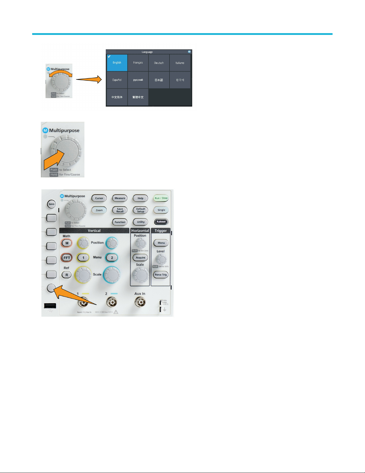
Getting acquainted with the oscilloscope
4. Push the Multipurpose knob to select the highlighted language. The selected language takes effect immediately.
5. Push the Menu On/Off button to close the Utility menu.
6. If you load a language other than English, install the plastic overlay on the front panel to provide labels in that language. Fold the
overlay tabs. Push the overlay over the knobs until the knob hole tabs click over the bottom edges of the knobs. Insert the overlay tabs
into the small slots.
If you are changing from a non English language to English, remove the front-panel language overlay.
TBS1000C Series Oscilloscopes User Manual 37
Page 38

Getting acquainted with the oscilloscope
Changing the date and time
Set the current date and time so that files that you save are marked with the correct date and time. The date and time are shown in the
lower-right corner of the screen. Time is shown using a 24-hour clock.
Note: The clock does not automatically adjust for seasonal time changes. The calendar does adjust for leap years.
The following steps show how to set the oscilloscope clock with the current date and time. These steps also introduce you to more
functions of the menu system.
1. Push Utility front-panel button.
2. Push -More- Page 1/2 side-menu button.
3. Push Display & Date side-menu button. Turn the Multipurpose knob to select Display Date & Time option. The oscilloscope shows
the Set Date & Time menu.
TBS1000C Series Oscilloscopes User Manual 38
Page 39

4. Turn the Multipurpose knob to select the Year field.
Getting acquainted with the oscilloscope
5. Click the Multipurpose knob to enable setting the year value. A white box is drawn around the number field, indicating that you can
use the Multipurpose knob to change that value.
6. Turn the Multipurpose knob to change the year value in the field.
When the value is correct, click the Multipurpose knob. This enters the number and returns the knob to menu select mode.
7. Repeat steps 2 - 5. to select and change the remaining date and time settings (Month, Day, Hour, Minute).
TBS1000C Series Oscilloscopes User Manual 39
Page 40

Getting acquainted with the oscilloscope
8. When you have finished making all date and time changes, turn the Multipurpose knob to select Apply, then click the knob to enter
the date/time settings into the oscilloscope.
9. To turn off displaying the date and time, select Display Date & Time and click the Multipurpose knob to toggle On or Off.
10. Push the Menu On/Off button to close the Utility side menu.
The new date and time are shown in the lower-right corner of the screen.
TBS1000C Series Oscilloscopes User Manual 40
Page 41

Supported probe types
Getting acquainted with the oscilloscope
For more information on the many probes available for use with TBS1000C Series oscilloscopes, visit the Oscilloscope Probe and
Accessory Selector tool on the Tektronix Web site (www.tek.com).
Reducing electrostatic damage while taking measuremens
Static electricity that builds
up on your body can damage
static-sensitive components. If
you are working with staticsensitive components, ground
yourself when using probes.
Wearing a grounding strap
safely sends static charges on
your body to earth ground.
Connect the grounding strap
to the oscilloscope ground, or
to the same ground circuit that
the oscilloscope is connected
to.
Doing a functional check
Perform this quick functional check to verify that your oscilloscope is operating correctly.
Connect the oscilloscope power cable as described
in Powering On the Oscilloscope. See Powering the
oscilloscope on page 34.
Table continued…
TBS1000C Series Oscilloscopes User Manual 41
Page 42

Power on the oscilloscope.
Connect a probe to channel 1.
Getting acquainted with the oscilloscope
Connect the probe tip and ground lead to the PROBE COMP
connectors on the oscilloscope front panel. The probe tip
connects to the 5 V connector, and the ground clip connects to
the ground connector.
Push Default Setup. Default Setup returns the oscilloscope
settings to factory default values. See The default oscilloscope
settings Default Setup on page 138.
Table continued…
TBS1000C Series Oscilloscopes User Manual 42
Page 43

Push Autoset.
The screen displays a square wave.
Getting acquainted with the oscilloscope
If the displayed square wave tops are not flat, perform
the procedures to compensate the probe high frequency
response. You can compensate the probe after completing
this functional check.
Push Measure to open the Measurement Selection menu.
Table continued…
TBS1000C Series Oscilloscopes User Manual 43
Page 44

Turn the Multipurpose knob to select Snapshot.
Click the Multipurpose knob to show the Snapshot screen.
See Taking a measurement snapshot on page 81.
Verify that the Frequency value is ~1 kHz and the Period
value is ~1 ms, respectively.
Getting acquainted with the oscilloscope
Push the Menu On/Off button to close the Snapshot
screen. Push the Menu On/Off button again to close the
Measurement screen.
What is Autoset
The functional check used the Autoset button to display a stable waveform. Autoset automatically adjusts the oscilloscope acquisition,
horizontal, trigger, and vertical controls to display five or six waveform cycles for an active (displayed) channel. This powerful function can
save you time when you need to view an unknown signal. See the Autoset topic for more information. See Using Autoset on page 67.
Probes and ground leads tip
TBS1000C Series Oscilloscopes User Manual 44
Page 45

When taking a real measurement, use the shortest
possible ground lead and signal path to minimize probeinduced ringing and distortion on the measured signal.
Getting acquainted with the oscilloscope
Signal with a short length ground
lead
Signal with a long ground lead
Getting on-screen help for settings HelpEverywhere™
HelpEverywhere™ is a mode that displays graphics and short text descriptions when you access the menus for most oscilloscope
settings. This is very useful for when you are first learning the functions of oscilloscope controls.
You can enable HelpEverywhere™ content for all supported settings, or enable it for specific function groups, such as Trigger controls,
Vertical controls, and so on.
1. Push the Help front-panel button.
2. Push the HelpEverywhere™ side-menu button to display the menu. All HelpEverywhere™ content is set to Off by default except for
the Measurement category, which is On.
TBS1000C Series Oscilloscopes User Manual 45
Page 46

Getting acquainted with the oscilloscope
3. To turn all HelpEverywhere™ content on or off, use the Multipurpose knob to select Set All to On or Set All to Off, then click the
knob.
4. To set individual menu categories to show HelpEverywhere™, use the Multipurpose knob to select a category, then click the knob to
toggle that selection On or Off.
TBS1000C Series Oscilloscopes User Manual 46
Page 47

Getting acquainted with the oscilloscope
The next time you access a HelpEverywhere™ supported menu setting, the oscilloscope displays the help for that item.
You may need to turn the Multipurpose knob and select another menu item to show the HelpEverywhere™ content.
Note:
When any HelpEverywhere™ content is enabled, the HelpEverywhere™ icon is highlighted (in upper right corner of screen).
Signal path compensation SPC
Signal Path Compensation (SPC) corrects for DC level inaccuracies in the internal signal path caused by temperature variations and/or
long-term signal path drift. You should run the SPC whenever the ambient (room) temperature has changed by more than 10 °C, or once
a week if you use vertical scale settings of 5 mV per division or less. Failure to run a SPC may result in the oscilloscope not meeting
warranted performance levels at those volts per division settings.
To compensate the signal path for all channels:
1. Power on and warm up the oscilloscope for at least 20 minutes.
TBS1000C Series Oscilloscopes User Manual 47
Page 48

Getting acquainted with the oscilloscope
2. IMPORTANT: Remove all input signals (probes and cables) from channel inputs and the Aux In connector on the front of the
oscilloscope.
3. Push Utility.
4. Push the Calibration & Diagnostic side-menu button.
5. Turn the Multipurpose knob to select Signal Path, then click the Multipurpose knob to start the SPC process.
The oscilloscope shows a Signal Path Compensation information message.
6. Push the Compensate Signal Paths side-menu button to start the process.
The screen shows rotating dots while the SPC is run. The oscilloscope displays a message when the SPC is complete. SPC can take
several minutes to run, so wait until the oscilloscope shows a message that SPC is completed.
7. Push Menu Off to remove the message and menus.
8. Reconnect probes to the oscilloscope.
The Scope Intro function
The Scope Intro function provides a brief history of oscilloscopes, some basic oscilloscope concepts, and an overview of the oscilloscope
features and controls.
You can view any topic in any order.
1. Push the Help front-panel button.
TBS1000C Series Oscilloscopes User Manual 48
Page 49

Getting acquainted with the oscilloscope
2. Push the Scope Intro side-menu button.
3. Use the Multipurpose knob to select and click a topic heading.
4. Use the Multipurpose knob to select and click a topic to read.
5. Push the relevant side-menu button to return to the menu for the subject category, and select and click the next topic to view.
6. When you are done viewing the topics for that category, push the Scope Intro side-menu button to return to the main menu, and select
a new category to read.
7. Push the Menu On/Off button to close the Scope Intro mode.
The Scope Intro function does not remember which topics you have read.
Note:
TBS1000C Series Oscilloscopes User Manual 49
Page 50

Sampling oscilloscope concepts
Sampling oscilloscope concepts
Sampling and acquisition concepts
Before the oscilloscope can display or measure a signal, it must be sampled. Sampling is the process of measuring the input signal
amplitude value at regular intervals (called the sampling rate, in samples per second), converting the sampled levels into digital data, and
storing the sampled values in memory to create a waveform record. The oscilloscope uses the digitized values in the waveform record to
create, display, and measure waveforms. Each oscilloscope channel has its own waveform record memory storage.
TBS1000C Series oscilloscopes use real-time sampling. In real-time sampling, the oscilloscope samples and digitizes all of the sampled
points at one time, in sequence, stores the sampled data in memory, and then repeats the sampling and storage process.
Use the Horizontal Scale knob to change the sample rate (samples per second). The oscilloscope automatically sets the sample rate so
that there are more than enough samples to accurately capture the signal information. The sample rate is shown on the screen at all times
in the horizontal position/scale readout.
Note:
• The maximum sample rate of 1 GS/s is available on both channels, when both channels are active.
You can set the waveform record length (number of sample points in the waveform record) from 1000 points to 20k points. A longer
(larger) waveform record is useful to capture several waveform cycles to search for a waveform of interest, or to capture a great deal of
detail for just a few waveform cycles and then use the Zoom function to search the waveform for areas of interest.
Each time the oscilloscope fills the waveform record is called a waveform acquisition, or acquisition for short. Each acquisition stores
new sample data into the same waveform record for that channel.
A waveform record is further divided into acquisition intervals, which are equally sized groups of samples. Acquisition intervals let the
oscilloscope perform calculations to analyze and display data such as the minimum and maximum data values per interval, or the average
signal value per interval. How the values in the acquisition interval are used is set by the acquisition mode.
Acquisition mode concepts
The acquisition mode sets how the oscilloscope uses the sampled data points in each acquisition interval to create and display a
waveform. You can set the acquisition mode to one of the following modes.
Sample mode retains and uses
the first sampled point from
each acquisition interval to
create the displayed waveform.
This is the default mode.
TBS1000C Series Oscilloscopes User Manual 50
Page 51

Peak Detect mode uses the
highest and lowest of all
the samples contained in
two consecutive acquisition
intervals. Use this mode
to help detect short rapid
transitions in a waveform.
Peak Detect is not available
at faster time per division
settings.
Hi Res mode oversamples
lower-frequency signals and
calculates the average of
all the samples for each
acquisition interval. Use Hi
Res mode to provide higherresolution (16-bit) sample
points for lower-frequency
waveforms.
Average mode calculates and
displays the average value
for each sample point over
a user-specified number of
acquisitions. Use Average
mode to reduce random noise.
Sampling oscilloscope concepts
Trigger concepts
The oscilloscope uses the data in the waveform record to construct and display a waveform on the oscilloscope screen. However, as the
oscilloscope is constantly acquiring samples into the waveform record, each waveform record starts at a random point of the input signal.
This means that the waveform record sample values are constantly changing, which results in a displayed waveform that is unstable or
jittering. An unstable waveform cannot be accurately measured, making this display useless except for very broad measurements (type of
signal, approximate peak to peak signal amplitude).
Figure 1: Untriggered display
What is needed is a way to set the oscilloscope to detect, or trigger on, the same signal condition or state on the input signal for each
waveform acquisition, and store the samples in the waveform record such that the same signal condition is at the same sample time
location in the waveform record.
A trigger sets when the oscilloscope detects a defined waveform condition, such as at a specified signal voltage level on the rising edge
of the signal. The oscilloscope uses that trigger condition to store the waveform samples in the waveform record so that the signal sample
point that meets the trigger condition is at the same location in the waveform record. When displayed, the waveform record for each
acquisition shows the waveform at the same trigger point, resulting in a stable waveform on the screen.
TBS1000C Series Oscilloscopes User Manual 51
Page 52

Sampling oscilloscope concepts
Figure 2: Triggered display
Understanding and using triggers is probably the most important skill needed to quickly display and analyze waveforms. A trigger condition
can be as simple as when the signal passes through a specified voltage level when going from a low level to a high level (positive slope). A
trigger condition can also be very specific, such as when the signal level is falling and the width of a single pulse of the signal is less than a
specified time period.
The trigger point in a waveform record also sets the zero time-reference point in a waveform record. By default, the trigger point in a
waveform record is in the center of the waveform record. This means that half of the record shows the signal waveform before the trigger
condition (pretrigger), and the other half shows the waveform after the trigger condition (post-trigger).
Pretrigger data can help you troubleshoot signal problems. For example, to find the cause of an unwanted glitch in your test circuit, trigger
on the glitch signal and look at the pretrigger waveform. By analyzing what happens before the glitch, you may uncover information that
helps you find the source of the glitch.
Trigger slope and level concepts
The oscilloscope must detect both the slope and level conditions before it can trigger and display a stable waveform.
The minimum trigger conditions needed to display a stable waveform are the signal slope and threshold level. The slope sets the
oscilloscope to find the trigger point on the rising or the falling edge of a signal. The level sets where on that edge the trigger point occurs.
The trigger Slope sets the
oscilloscope to find the trigger
event on the rising or the
falling edge of a signal.
The trigger threshold Level
(or just level) is the signal
amplitude value on a slope
that must occur for the
oscilloscope to trigger on a
signal.
TBS1000C Series Oscilloscopes User Manual 52
Page 53

A runt trigger needs two
thresholds to define the two
levels that a signal must pass
through to be considered a
valid (nonrunt) signal.
The arrow at the far right of
the screen marks the threshold
level(s) for that signal.
Turning the Trigger Level knob
changes the threshold level
and momentarily displays a
long horizontal line (or two
lines for a runt trigger) across
the waveform to show the
trigger level(s) in relation to
the overall waveform.
Available trigger types
The oscilloscope lets you trigger on several signal conditions:
Sampling oscilloscope concepts
Trigger type Trigger conditions
Edge Edge triggers are the simplest and most commonly used trigger type. An edge
trigger event occurs when the trigger source passes through a specified voltage
threshold (trigger level) when the signal is transitioning in the specified slope
(rising or falling).
You can trigger on a rising or falling edge, as defined by the slope control.
Pulse
Width
Runt A runt pulse is a pulse that crosses one threshold but fails to cross a
You can trigger on pulses that are less than, greater than, equal to, or not equal
to a specified time period. You can trigger on positive or negative pulses.
Pulse width triggers are primarily used to analyze digital signals.
second threshold before recrossing the first. Therefore, a runt trigger needs
two thresholds to define the two levels that a signal must pass through to be
considered a valid (nonrunt) signal.
You can trigger on any positive or negative (or either) runt signal. You can also
trigger on runt signals with pulse widths that are less than, greater than, equal
to, or not equal to a specified width.
Runt triggers are primarily used to analyze digital signals.
Trigger coupling
Trigger coupling sets what part of the input signal is used by the trigger circuit. Trigger coupling choices are DC, LF Reject, HF Reject, and
Noise Reject.
TBS1000C Series Oscilloscopes User Manual 53
Page 54

Sampling oscilloscope concepts
• DC Coupling passes the trigger signal to the trigger circuit with no filtering. The scope may trigger on false events if the signal is noisy.
• HF Reject attenuates signals above 85 kHz from the trigger circuit. This reduces false triggering on high-frequency noise when
measuring lower-frequency signals.
• LF Reject attenuates signals below 65 kHz from the trigger circuit. This reduces false triggering from low frequency noise when
measuring higher-frequency signals.
• Noise Reject reduces the trigger circuit input sensitivity. This reduces false triggering when measuring signals with higher levels of
noise.
Trigger modes
The Trigger Mode sets how the oscilloscope behaves in the absence or presence of a trigger. Trigger mode also enables the trigger holdoff
function.
Auto Untriggered Roll trigger mode
The Auto (Untriggered Roll) mode sets the oscilloscope to acquire a waveform even if a trigger does not occur. Auto mode uses a timer
that starts when the acquisition is started, and the pretrigger information is obtained. If a trigger event is not detected before the timer times
out, the oscilloscope forces a trigger. The length of time it waits for a trigger event depends on the time base setting (Horizontal Scale).
Auto mode, when forcing triggers in the absence of valid triggering events, does not synchronize the waveform on the display. The
waveform will appear to roll across the screen. If valid triggers occur, the display will become stable.
Normal trigger mode
Normal mode sets the oscilloscope to acquire a waveform only when a trigger condition occurs. If no trigger occurs, the last waveform
record acquired remains on the display. If no last waveform exists, no waveform is displayed.
Holdoff trigger mode
The Holdoff trigger mode lets you set a time period during which the oscilloscope ignores trigger events. For example, to trigger on the
first pulse of a pulse burst, you would set the trigger conditions to trigger on a positive edge, and set the holdoff value so that the trigger
is disabled for a period of time after the trigger event but before the next bust occurs. Using Holdoff in this case prevents the oscilloscope
from triggering on any positive signal edge.
Use Set Holdoff to minimum to set the holdoff value to the minimum value.
The trigger mode does not set the trigger conditions; those are set with the trigger Type controls. See Available trigger
Note:
types on page 53.
Trigger delay acquisition mode
In normal acquisition modes, the trigger point is located at the center of the waveform record, and is positioned at the center-screen
expansion point so that horizontal scale changes are centered around the trigger point. The Delay function in the Acquire menu
disconnects the trigger point from the center-screen expansion point. This feature lets you use the Horizontal Position knob to reposition
(delay) the trigger point from the expansion point by a specified amount.
TBS1000C Series Oscilloscopes User Manual 54
Page 55

Sampling oscilloscope concepts
The most common use for Delay is to acquire and display waveform detail that is separated after the trigger event by a significant interval
of time. For example, you can trigger on a pulse that occurs once every 10 ms and then use Delay to look at the signal characteristics that
occur 6 ms after the trigger point.
TBS1000C Series Oscilloscopes User Manual 55
Page 56

Setting channel input parameters
Setting channel input parameters
Use the Vertical Menu buttons to select the waveform to be displayed or open the menu options used to set the input parameters for each
channel. Setting for each channel are independent of the other channel.
Setting input signal coupling
Input signal coupling sets how the input signal is passed to the oscilloscope sampling circuit.
1. Push the Vertical Menu button for the channel input that you want to set.
2. Push -More- Page 1/2 side-menu button.
3. Push the Coupling side-menu button.
4. Use the Multipurpose knob to select and click the coupling type:
DC coupling passes both AC and DC signal components.
AC coupling blocks the DC component and passes only the AC signal.
Inverting the input signal
Use this procedure to invert (flip vertically) the signal. A typical reason to invert a signal is to use the inverted signal to create a math
waveform.
1. Push the Vertical Menu button for the channel input that you want to set.
2. Push -More- Page 1/2 side-menu button.
3. Push the Invert side-menu button to toggle between Off for normal operation and On to invert the polarity of the signal in the
preamplifier.
TBS1000C Series Oscilloscopes User Manual 56
Page 57

Setting channel input parameters
Setting the oscilloscope bandwidth
Use this procedure to set the oscilloscope bandwidth. Bandwidth is the maximum frequency that an oscilloscope can accurately display
and measure. The oscilloscope gradually attenuates (reduces) the signal level of frequencies that are higher than the bandwidth. This
means that although you can display signals that are above the bandwidth limit, their amplitude values and other characteristics are not
guaranteed to be accurate.
1. Push the Vertical Menu button for the channel input that you want to set.
2. Push -More- Page 1/2 side-menu button.
3. Push the Bandwidth side-menu button.
4. Use the Multipurpose knob to select and click the bandwidth setting.
• Full sets the bandwidth to the maximum bandwidth of which the oscilloscope is capable.
• 20 MHz sets the bandwidth to 20 MHz.
Setting the probe type voltage or current
The Probe Type submenu sets the type for probe that is connected to the oscilloscope. The default probe type is Voltage. The other valid
probe type is current.
Push the Vertical Menu button
for the channel input that you
want to set.
Push the Probe Setup side
menu to display the Probe
Setup submenu.
Use the Multipurpose knob to
select and click Probe Type
submenu item.
Select and click the probe type
(Voltage or Current).
TBS1000C Series Oscilloscopes User Manual 57
Page 58

Setting channel input parameters
Setting the probe attenuation factor
Attenuation is the amount that the probe reduces or amplifies the input signal amplitude before sending it to the oscilloscope input. The
Attenuation submenu sets the probe attenuation factor for probes. The default attenuation is 10x.
Push the Vertical Menu button
for the channel input that you
want to set.
Push the Probe Setup side
menu to display the Probe
Setup submenu.
Use the Multipurpose knob
to select and click the
Attenuation submenu item.
Use the Multipurpose knob
to select and change the
attenuation factor.
Quickly setting the probe attenuation to 1X or 10X
The Set To 1X and Set To 10X submenu items let you quickly set the probe attenuation to either 1X or 10X.
Push the Vertical Menu button
for the channel input that you
want to set.
Push the Probe Setup side
menu to display the Probe
Setup submenu.
Use the Multipurpose knob to
highlight either Set To 1X or
Set To 10X submenu item.
Then click the Multipurpose
knob to set that value.
TBS1000C Series Oscilloscopes User Manual 58
Page 59

Setting channel input parameters
Setting the measure current mode for voltage probes
If you are measuring current by using a standard voltage probe to measure the voltage drop across a resistor, use the Measure Current
field to set the Amps/Volts or Volts/Amps ratio of your measurement setup. For example, if you are measuring the voltage drop across a
2 Ω resistor to determine the current, set the V/A ratio to 2.
Push the Vertical Menu button
for the channel input that you
want to set.
Push the Probe Setup side
menu to display the Probe
Setup submenu.
Use the Multipurpose knob to
highlight the Measure Current
submenu item.
Push the Multipurpose knob to
toggle between Yes and No.
If you select Yes, the area
below the Measure Current
submenu displays the Amps/
Volts or Volts/Amps ratio menu
item. Use the Multipurpose
knob to select and change
the current measurement
parameter.
Setting the input signal vertical offset
The Offset menu lets you set the vertical signal offset, which changes the waveform position relative to the oscilloscope ground (0 volts)
reference. This menu also lets you quickly set a signal’s vertical offset to 0. See The difference between vertical position and vertical
offset on page 60.
Push the Vertical Menu button
for the channel input that you
want to set.
TBS1000C Series Oscilloscopes User Manual 59
Page 60

Setting channel input parameters
Push the Offset side-menu
button.
To set a specific offset
voltage, use the Multipurpose
knob to select and click the
offset value field. Use the
knob to change the value;
the waveform on the screen
moves as you change the
value. Click the knob again to
exit the field.
To set the offset value to 0,
use the Multipurpose knob to
select and click Set to 0.
Setting the waveform vertical position
To quickly position a waveform position, use the Vertical Position knob on the front panel for the channel that you want to move.
The Position submenu lets you set the vertical signal position, which moves the waveform up or down on the screen. This menu also lets
you quickly set the waveform 0 (ground) value to the center horizontal graticule. See The difference between vertical position and vertical
offset on page 60.
1. Push the Vertical Menu button for the channel input that you want to set. Each channel’s settings are independent of the other
channels.
2. Push the Position side-menu button to select and show the Position submenu.
3. To set a specific position value, use the Multipurpose knob to select and click the position field. Use the knob to change the value; the
waveform on the screen moves as you change the value. Click the knob again to exit the field.
4. To set the position to 0 (center graticule), use the Multipurpose knob to select and click Set to 0.
The difference between vertical position and vertical offset
• Vertical position is a display function that moves the waveform image on the screen. Moving the signal on the screen does not change
the ground (0 volt) baseline level for that signal.
• Vertical offset is a signal function that adds a DC voltage to the input signal before the oscilloscope preamplifier. Adding this DC
voltage moves, or offsets, the signal from the ground (0 volts) level. You use offset to increase the effective dynamic range of a signal.
For example, you can set the vertical offset to match the peak area of a signal, use the Vertical Position knob to move the peak area
to the center graticule, and then set the Vertical Scale knob to smaller voltage/division settings to look at more detail in that waveform
peak area.
TBS1000C Series Oscilloscopes User Manual 60
Page 61

Setting channel input parameters
Setting channel deskew
Deskew compensates for differences in signal delays between different cable lengths or probe types. Use Deskew to adjust the signal
delay for individual channels so that all signals arrive at the oscilloscope at the same time. Deskewing channels lets you take accurate
time-related measurements between two or more channels, or when using a current probe with a voltage probe.
Select one probe as a reference signal and adjust the deskew values for the other channels so that they all align. For best results, use a
deskew fixture, such as the Tektronix 067-1686-xx.
The following image shows before and after using deskew to set channel 1 and 2 deskew to minimize the delay with channel 1.
Push the Vertical Menu button
for the channel input that you
want to set.
Push the More side-menu
button.
Use the Multipurpose knob to
select and click Deskew.
To set a specific deskew delay,
use the Multipurpose knob to
select and click 0s. Then use
the knob to change and set the
value. The waveform on the
screen moves as you adjust
the value.
To set the deskew to the
oscilloscope default (0 delay),
use the Multipurpose knob to
select and click Set to Default.
Deskew tips
• Deskew settings are stored in nonvolatile memory until changed manually for each channel.
TBS1000C Series Oscilloscopes User Manual 61
Page 62

• Deskew settings are included in saved setup files.
• Doing a Default Setup resets deskew values to 0 on all channels.
Setting channel input parameters
TBS1000C Series Oscilloscopes User Manual 62
Page 63

Trigger setup
Triggering on a waveform edge
Use this procedure to set the oscilloscope to trigger on the rising or falling edge of a waveform.
1. Push the Trigger Menu front-panel button.
Trigger setup
2. Push the Type side-menu button.
3. Use the Multipurpose knob to select and click Edge.
4. Push the Source side-menu button and use the Multipurpose knob to select and click the channel to use as the trigger signal source,
or select AC Line to use the AC power source frequency as the trigger signal.
5. Push the Slope side-menu button to select between rising and falling slope edges on which to trigger the oscilloscope.
6. Push the Level side-menu button and use the Multipurpose knob to select and click the trigger level entry method:
• Click Level and use the Multipurpose knob to manually set the trigger level.
• Click Choose Preset and use the Multipurpose knob to set the trigger level to a predefined signal logic family level (TTL, CMOS,
ECL, and so on) or to 0.
• Click Set to 50% to set the trigger level to 50% of the signal peak-to-peak level.
7. Push -More- Page 1/2 side-menu button.
8. Push the Coupling side-menu button and use the Multipurpose knob to select and click the trigger coupling. See Trigger
coupling on page 53.
You can use the Trigger Level knob to immediately change the trigger level and momentarily display a long horizontal line
Note:
(or two lines for a Runt trigger) across the waveform to show the trigger level(s) in relation to the waveform.
Push the Trigger Level knob to immediately set the trigger to 50% of the signal peak-to-peak level.
TBS1000C Series Oscilloscopes User Manual 63
Page 64

Trigger setup
Triggering on a specified pulse width
Use this procedure to set the oscilloscope to trigger on a specified signal pulse condition. You can trigger when a pulse is less than, greater
than, equal to, or not equal to a set time period (width). The minimum pulse width setting is 1 ns. See Available trigger types on page 53.
Pulse width triggering is most often used to troubleshoot or analyze digital signals.
1. Push the Trigger Menu front-panel button.
2. Push the Type side-menu button.
3. Use the Multipurpose knob to select and click Pulse Width.
4. Push the Source side-menu button and use the Multipurpose knob to select and click the channel to use as the trigger signal source.
5. Push the Polarity side-menu button and use the Multipurpose knob to select and click the pulse polarity (positive or negative) to
trigger on.
6. Push the Threshold side-menu button and use the Multipurpose knob to select and click the trigger level entry method:
• Click the threshold field and use the Multipurpose knob to manually set the trigger level.
• Click Choose Preset and use the Multipurpose knob to set the trigger level to a predefined signal logic family level (TTL, CMOS,
ECL, and so on) or to 0.
• Click Set to 50% to set the trigger level to 50% of the signal peak-to-peak level.
7. Push -More- Page 1/2 side-menu button.
8. Push the Trigger When side-menu button and use the Multipurpose knob to select and click the pulse width condition on which to
trigger. Then use the Multipurpose knob to enter the pulse width time parameter.
Triggering on a runt pulse
Use this procedure to set the oscilloscope to trigger when a runt pulse occurs. You can also trigger when a runt pulse is less than, greater
than, equal to, or not equal to a set time period (width).
A runt pulse is a pulse that crosses one threshold level but fails to cross a second threshold before recrossing the first. Therefore, a runt
trigger needs two threshold levels to define the two levels that a signal must pass through to be considered a valid (nonrunt) signal. See
Available trigger types on page 53.
Runt pulse triggering is most often used to troubleshoot or analyze digital signals.
The minimum runt pulse width setting is 1 ns.
1. Push the Trigger Menu front-panel button.
TBS1000C Series Oscilloscopes User Manual 64
Page 65

Trigger setup
2. Push the Type side-menu button.
3. Use the Multipurpose knob to select and click Runt.
4. Push the Source side-menu button and use the Multipurpose knob to select and click the channel to use as the trigger signal source.
5. Push the Polarity side-menu button and use the Multipurpose knob to select and click the runt pulse polarity (positive, negative, or
either) to trigger on.
6. Push the Thresholds side-menu button and use the Multipurpose knob to select and click the trigger levels (thresholds) to use to
detect a runt pulse:
• Click High and use the Multipurpose knob to manually set the level that defines a valid high signal threshold level.
• Click Low and use the Multipurpose knob to manually set the level that defines a valid low signal threshold level.
• Click Choose Preset and use the Multipurpose knob to set the trigger threshold levels to predefined signal logic family levels
(TTL, CMOS, ECL, and so on) or to 0.
7. Push -More- Page 1/2 side-menu button.
8. Push the Trigger When side-menu button and use the Multipurpose knob to select and click Runt Occurs to trigger on any runt
event. If triggering on a runt width, use the Multipurpose knob to select and click the runt pulse width condition to test for, and enter
the runt width time parameter.
Setting the trigger mode
Use this procedure to set the oscilloscope trigger Mode. The trigger mode sets how the oscilloscope behaves in the absence or presence
of a trigger. Trigger mode also enables the trigger holdoff function. See Trigger modes on page 54.
Trigger mode does not set the trigger conditions; those are set with the Trigger Type side-menu buttons.
1. Push the Trigger Menu front-panel button.
TBS1000C Series Oscilloscopes User Manual 65
Page 66

Trigger setup
2. Push -More- Page 1/2 side-menu button.
3. Push the Mode side-menu button.
4. Use the Multipurpose knob to select and click a trigger mode or holdoff mode:
• Click Auto (Untriggered Roll) to set the oscilloscope to acquire and display a waveform even if a trigger does not occur. If there is
no valid triggering event, the waveform will appear to roll across the screen.See Auto Untriggered Roll trigger mode on page 54.
• Click Normal to set the oscilloscope to acquire and display a waveform only when a valid trigger event occurs. See Normal trigger
mode on page 54.
• Click Holdoff to set a time period after a trigger event, during which the oscilloscope ignores new trigger events. Once the holdoff
period is over, the oscilloscope starts looking for the trigger condition. See Holdoff trigger mode on page 54.
• Click Set Holdoff to Minimum to set the HoldOff value to the minimum value. The minimum holdoff period is 20 ns.
Trigger on an external signal using the AUX input
Use this procedure to trigger the instrument from an external signal connected to the AUX input.
1. Push the Trigger Menu front-panel button.
2. Push the Trigger Type side-menu button.
3. Use the Multipurpose knob to select and click Edge trigger type.
4. Push the Source side-menu button.
5. Use the Multipurpose knob to select and click AUX source.
The Aux setting is available only for the Edge and Pulse Width trigger types.
Note:
6. Set the values for Coupling, Level and Slope to trigger on the AUX connector signal.
TBS1000C Series Oscilloscopes User Manual 66
Page 67

Acquisition setup
Acquisition setup
Using Autoset
Autoset is a fast way to acquire and display a waveform. Autoset automatically sets the trigger type to edge, sets the threshold level to
50% of the signal level, and analyzes the input signal and adjusts the oscilloscope acquisition, horizontal, and vertical settings to display
five to six waveform cycles. Autoset is ideal for quickly displaying a repeating signal waveform.
Complete the following steps to Autoset:
1. Connect a probe to the oscilloscope and signal source.
2. Push the Vertical Menu button for the channel input that you want to Autoset, to enable that channel.
3. Push Autoset. The oscilloscope takes a few moments to analyze and display the signal.
4. You can push the Undo Autoset side-menu button to undo the last Autoset.
Autoset tips
• If more than one channel is active, Autoset triggers on the lowest-numbered displayed channel, and displays all active channels from
the top to the bottom of the screen.
• Autoset always sets vertical offset to 0 V.
• Channel 1 is a special case: If all channels are off (not displayed), or channel 1 is on, Autoset attempts to detect, trigger, and display
the waveform for channel 1 even if no signal is present (resulting in a flat waveform for channel 1). It will not trigger on, or display the
other channels, even if there are signals present on those channels.
TBS1000C Series Oscilloscopes User Manual 67
Page 68

How to enable/disable Autoset in the oscilloscope
Use this procedure to enable/disable the Autoset function to set up a waveform manually.
Note: To disable or enable the Autoset function requires a password. The default factory password is 000000.
1. Push Utility.
Acquisition setup
2. Push Feature Enable side-menu button.
3. Use the Multipurpose knob to select and click Autoset Enable. The oscilloscope opens the Feature Enable password entry screen.
TBS1000C Series Oscilloscopes User Manual 68
Page 69

Acquisition setup
4. Use the Multipurpose knob and side-menu buttons to enter the password that lets you disable Autoset. The factory default password
is 000000.
5. Push OK side-menu button to enter the password and let you disable Autoset.
How to change the Autoset password
Use this procedure to change the Autoset enable/disable password. Autoset requires a password to enable or disable the Autoset mode.
1. Push Utility.
2. Push Feature Enable side-menu button.
3. Use the Multipurpose knob to select and click Autoset Enable.
4. Use the Multipurpose knob to select and click Change Password. The oscilloscope opens the Change Password entry screen.
TBS1000C Series Oscilloscopes User Manual 69
Page 70

Acquisition setup
5. Use the Multipurpose knob and side-menu buttons to select alphanumeric and enter characters for the current password. Then push
the OK side-menu button. The factory default password is 000000.
6. Use the Multipurpose knob and side-menu buttons to enter the new password. Then push the OK side-menu button. Reenter the new
password to confirm it and push the OK side-menu button.
Note: The Autoset enable/disable can be done using the PI commands. Refer Programmer manual for detailed instructions.
Starting and stopping an acquisition
After you have defined the acquisition and trigger parameters, start acquiring and displaying a waveform with the Run/Stop or Single
controls.
TBS1000C Series Oscilloscopes User Manual 70
Page 71

Acquisition setup
Single sets the trigger mode
to Normal for the single
acquisition.
Setting the acquisition mode
Use the Acquisition mode to set how the oscilloscope uses the sampled data points in each acquisition interval to create and display a
waveform. See Acquisition mode concepts on page 50.
1. Push Acquire.
2. Push the Mode side-menu button.
3. Turn the Multipurpose knob to select a mode (Sample, Peak Detect, Hi res, Average), then click the Multipurpose knob to enable
that mode.
4. If you select Average, use the Multipurpose knob to select of how many acquisitions to average to create the waveform.
Sampling frequency for Peak Detect and Hi res modes are limited to 250MS/s. You can zoom in to view the waveforms in
Note:
lower horizontal scales.
TBS1000C Series Oscilloscopes User Manual 71
Page 72

Setting the acquisition trigger delay time
Push Acquire.
Acquisition setup
Push the Delay side-menu
button to toggle between On
and Off. When set to Off, the
expansion point is tied to the
trigger point so that horizontal
scale changes are centered
around the trigger point.
With Delay set to On, the
trigger point is disconnected
from the expansion point. Turn
the Horizontal Position knob
to move the trigger point
away from the expansion point
(center graticule). The amount
of delay is shown in the
Horizontal Status area at the
bottom-center of the graticule,
referenced to 0 s (center
graticule).
The trigger point can move
off the screen; when this
happens, the trigger marker
changes to show the direction
of the trigger point.
Trigger point is off-screen
(delay time shown on readout
at bottom of the screen)
Trigger point is off-screen (delay time shown on readout at bottom of the screen
TBS1000C Series Oscilloscopes User Manual 72
Page 73

Once you are displaying a
waveform area of interest at
the center of the screen, adjust
the Horizontal Scale knob to
acquire more points for the
area of interest, and use the
controls to view more detail.
Push the Set Horizontal
Position to 0s side-menu
button to return the trigger
point to the center of the
waveform record (setting delay
to 0). Pushing this button does
not turn off the delay mode.
You can also push the frontpanel Horizontal Position knob
to return the trigger point to
the center of the waveform
record.
Trigger Delay is different than Trigger Holdoff. See Holdoff trigger mode on page 54.
Acquisition setup
Setting the record length
Use this procedure to set the record length. The record length sets how many samples (data points) are added to a waveform record.
Available record lengths are 1000, 2000, 20,000 points.
Push Acquire.
Push the Record Length sidemenu button.
Use the Multipurpose knob
to select and set the record
length.
TBS1000C Series Oscilloscopes User Manual 73
Page 74

Use longer record lengths to
either capture more samples
for a waveform record, or
capture more cycles of a
waveform, then use the Zoom
controls to investigate the
waveform in more detail.
Acquisition setup
Maximum zoomed waveform
record captured with 5000
points
Maximum zoomed waveform record captured with 5000 points
Using the roll display mode
Roll mode gives a display similar to a strip chart recorder, in that the waveform moves slowly, or rolls, from right to left on the screen.
Roll mode is used to display low-frequency signals. Roll mode lets you see acquired data points without waiting for the acquisition of a
complete waveform record.
Roll mode is not a button- or menu-selected mode, but is present when the trigger mode is Auto and the horizontal scale and record
lengths are set as follows:
Table 5: Roll mode is enabled when:
Horizontal scale setting Record length (number of samples)
40 ms/div 1000, 2000, 20k
Roll mode tips
• Push Run/Stop to halt Roll mode.
• Roll mode is disabled under the following conditions:
• When using Reference, Math, or FFT waveforms
• Using the Zoom function
• Taking measurements (Measure menu)
TBS1000C Series Oscilloscopes User Manual 74
Page 75

Acquisition setup
• When trigger mode is changed to Normal
• When horizontal scale is set to 40 ms/division or higher
Note: The Average acquisition mode is unavailable when you are using Roll mode.
Setting the oscilloscope to factory default values - Default Setup
Default Setup clears the current oscilloscope settings and loads factory-defined settings. This lets you quickly reset the oscilloscope to a
known state before setting up to take a new measurement.
See Setting the oscilloscope to factory default values - Default Setup on page 75.
To return the oscilloscope to its factory default settings:
Push Default Setup.
If you change your mind,
push Undo Default Setup sidemenu button to return the
oscilloscope to the settings
present before you pushed
Default Setup. You must push
this button before doing any
other action.
TBS1000C Series Oscilloscopes User Manual 75
Page 76

Waveform display settings
Displaying and removing a waveform
Use this procedure to turn on or off the display of each channel’s waveform.
To add or remove a waveform from the display, push the corresponding front-panel channel Menu button.
If the selected channel is already active, pushing the channel Menu button removes the waveform.
Waveform display settings
If the channel is not active, pushing the channel Menu button selects that channel; another push removes the waveform from the screen.
If more than one waveform is displayed on the screen, selecting a channel brings the corresponding waveform on top of all other
waveforms.
Setting the waveform persistence
Persistence sets the time for how long the oscilloscope retains and displays the sampled waveform points on the screen. Using longer or
infinite persistence time helps to display infrequent or random signal anomalies such as glitches.
Normal persistence sets the oscilloscope to erase the current waveform data as it draws the newest acquisition. Changing the persistence
time (from 1 second to 10 seconds) sets how long to retain waveform data points in memory and on the screen until they are erased. The
older data points are erased first.
Infinite persistence sets the oscilloscope to retain and display all acquisition waveform data points without erasing the previous data.
Changing an acquisition setting, such as Horizontal Position or Scale, Autoset, and Single, resets the persistence period to start over.
1. Push Acquire.
TBS1000C Series Oscilloscopes User Manual 76
Page 77

Waveform display settings
2. Push Waveform Display side-menu button.
3. Use the Multipurpose knob to select and click Persist Time.
4. Use the Multipurpose knob to change and set the Persist Time value. The range is Auto 0 s - 10 s (in one second increments), and
infinity.
Auto is not same as 0 seconds. Auto is persistence time that gives the most number of waveforms per second, for a given horizontal
scale. The range of persistence is 1s - 10s in the steps of 1s. There is an option to have persistence set to 0 seconds. This is mode
can be enabled when Persistence is set to OFF. When persistence is set to ON, there is an option to select the amount of persistence
in terms of time ranging from 1s -10s. Further, the amount of persistence can be set to Auto, that gives the best performance.
5. To clear the persistence of the displayed waveform, select and click Clear Persistence. This does not change the persistence setting,
but just clears the displayed waveform persistence data.
Waveform persistence tip
To quickly clear the displayed waveform persistence data, push Single, then push Run/Stop to restart active waveform acquisition.
Note: For FFT waveform, the behavior of the persistence will be as follows.
• Setting the persistence to infinite, will make the display to retain all the waveforms.
• Setting the persistence to ON (Auto 0 s - 10 s), will have the similar behavior as Persistence set to OFF.
The XY display mode
The XY display mode plots the signal amplitude of channel 1 (X) against the amplitude of channel 2 (Y), where channel 1 is the horizontal
axis and channel 2 is the vertical axis. XY display mode is useful for showing signal phase or frequency relationships between periodic
signals. The resulting XY plots are called Lissajou patterns.
You can display Ch 1 versus Ch 2 on two-channel models.
1. Select the two signal sources that you want to plot. Push the Vertical Position knob for each channel to set the ground reference of
both signals to 0 V (center horizontal graticule) so that the XY plot is centered on the screen.
TBS1000C Series Oscilloscopes User Manual 77
Page 78

2. Push Acquire.
Waveform display settings
3. Push -More- Page 1/2 side-menu button.
4. Push XY Display side-menu button to toggle XY display mode On and Off.
TBS1000C Series Oscilloscopes User Manual 78
Page 79

Waveform display settings
XY display mode tips
• Because the XY display is simply a different way of displaying pairs of waveforms, the underlying waveforms are available for
measurements, and for saving to reference memory or a USB drive for off-line analysis.
• Use a Web browser and search on the keyword “lissajou patterns” to find more information on XY plots.
Setting the backlight intensity
Use this procedure to change the overall screen lighting level. Higher settings are better for brightly lighted areas, and lower values are
better for dimly lit areas.
1. Push Utility.
2. Push -More- Page 1/2 side-menu button.
3. Push the Display & Date side-menu button.
4. Use the Multipurpose knob to select and click Backlight Intensity.
5. Use the Multipurpose knob to change and set the backlight value.
TBS1000C Series Oscilloscopes User Manual 79
Page 80

Analyzing a waveform
Analyzing a waveform
Taking automatic measurements
Automatic measurements are a way to quickly take common measurements on a waveform, such as signal frequency, period, rise and fall
times, and so on. You can take up to a total of six measurements at once, on any combination of input channels and a math waveform. The
measurements are shown on the main screen in the order they were selected.
To take an automatic measurement:
Acquire and display a
triggered waveform.
Push Measure.
Push the side-menu button to
select the channel on which to
take measurements.
Use the Multipurpose
knob to select and
click a measurement.
See Automatic measurement
descriptions on page 82.
The Measurement Selection
bar at the top of the screen
updates to show that a
measurement was selected for
that channel (indicated by
color), up to a maximum of six
measurements total to display.
Measurements with a down
triangle contain a list of the
input channels to use for that
measurement when selected.
Select and click the input
TBS1000C Series Oscilloscopes User Manual 80
Page 81

channels. Then push the Menu
On/Off button to close the list.
To unselect a measurement,
highlight that measurement
and click the Multipurpose
knob. To deselect a
measurement for a different
channel than the current
channel, push the side-menu
button for the channel of the
measurement, then use the
knob to select and click the
measurement to remove it.
To unselect all measurements,
push the Remove All
Measurements side-menu
button.
To close the measurement
menu and show the selected
measurements on the screen,
push the Menu On/Off button.
Measurements are shown on
the screen. Pushing the Menu
On/Off button also turns on or
off showing the measurements
on the screen.
Analyzing a waveform
Automatic measurements tip
A symbol appears next to a measurement if a vertical signal clipping condition exists. Part of the waveform is above or below the upper
or lower edge of the screen. Signal clipping causes inaccurate measurements. To obtain an accurate measurement, turn the Vertical
Scale and Position knobs so that all of the waveform is on the screen.
A symbol appears next to a measurement if the measurement accuracy is not guaranteed. Wait for measurement module to get proper
measurement. As soon as the proper measurement is available, the symbol will disappear.
Taking a measurement snapshot
The Snapshot measurement (in the Measurement menu) displays all single-channel measurements on one screen for a single acquisition
of one channel. You can view the snapshot results and save a screen image of the snapshot measurements to a file.
To take a measurements snapshot:
1. Acquire and display a triggered waveform.
2. Push Measure.
TBS1000C Series Oscilloscopes User Manual 81
Page 82

Analyzing a waveform
3. Push the side-menu button of the channel for which to show the measurement snapshot. You can only take a snapshot of one channel
at a time.
4. Use the Multipurpose knob to select and click Snapshot. The snapshot screen opens immediately.
5. If the File Save button is set to save an image, push the File Save button to save the snapshot image to a file. See Saving files to USB
with the Save File button on page 106.
6. Push the Menu On/Off button to close the Snapshot screen and return to the measurements menu.
Snapshot measurement tip
• The measurement snapshot does not mark a measurement if a vertical clipping condition exists. Clipping is where part of the waveform
is above or below the display. To obtain a proper measurement snapshot, use the Vertical Scale and Position knobs to make all of the
waveform appear in the display.
• You can also use Gating to analyze only a specified part of a waveform when you take a measurement snapshot. See Taking a
measurement on just a part of the waveform Gating on page 86.
Automatic measurement descriptions
The following tables list the automatic measurements, grouped as shown on the measurements menu. Measurement descriptions can
also be shown on the oscilloscope by enabling HelpEverywhere™ (Help > HelpEverywhere™). See Getting on-screen help for settings
HelpEverywhere™ on page 45.
Frequency measurement descriptions
TBS1000C Series Oscilloscopes User Manual 82
Page 83

Analyzing a waveform
Table 6: Frequency measurements
Measurement Description
Frequency The first cycle in a waveform or gated region. Frequency is the reciprocal of the period; it is
measured in hertz (Hz) where one Hz is one cycle per second.
+Pulses The number of positive pulses that rise above the mid reference crossing in the waveform or gated
region.
–Pulses The number of negative pulses that fall below the mid reference crossing in the waveform or gated
region.
+Edges The number of positive transitions from the low reference value to the high reference value in the
waveform or gated region.
–Edges The number of negative transitions from the high reference value to the low reference value in the
waveform or gated region.
Time measurement descriptions
Table 7: Time measurements
Measurement Description
Period The time required to complete the first cycle in a waveform or gated region. Period is the reciprocal
of frequency and is measured in seconds.
Rise Time The time required for the leading edge of the first pulse in the waveform or gated region to rise
from the low reference value to the high reference value of the final value.
Fall Time The time required for the falling edge of the first pulse in the waveform or gated region to fall from
the high reference value to the low reference value of the final value.
Table continued…
TBS1000C Series Oscilloscopes User Manual 83
Page 84

Analyzing a waveform
Measurement Description
DelayRR The time between the mid reference (default 50%) amplitude point of the rising edge of two
different waveforms. See also Phase.
This measurement requires inputs from two channels.
DelayRF The time between the mid reference (default 50%) amplitude point of the rising edge of one
waveform and the falling edge of a second waveforms. See also Phase.
This measurement requires inputs from two channels.
DelayFR The time between the mid reference (default 50%) amplitude point of the falling edge of one
waveform and the rising edge of a second waveforms. See also Phase.
This measurement requires inputs from two channels.
DelayFF The time between the mid reference (default 50%) amplitude point of the falling edge of one
waveform and the falling edge of a second waveforms. See also Phase.
This measurement requires inputs from two channels.
Phase The amount of time that one waveform leads or lags another waveform, expressed in degrees,
where 360° makes up one waveform cycle. See also Delay(RR, RF, FR, FF).
This measurement requires inputs from two channels.
+Width Positive pulse width. The distance (time) between the mid reference (default 50%) amplitude
points of a positive pulse. The measurement is made on the first pulse in the waveform or gated
region.
–Width Negative pulse width. The distance (time) between the mid reference (default 50%) amplitude
points of a negative pulse. The measurement is made on the first pulse in the waveform or gated
region.
+Duty The ratio of the positive pulse width to the signal period expressed as a percentage. The duty cycle
is measured on the first cycle in the waveform or gated region.
–Duty The ratio of the negative pulse width to the signal period expressed as a percentage. The duty
cycle is measured on the first cycle in the waveform or gated region.
Burst Width The duration of a burst (a series of transient events) and is measured over the entire waveform or
gated region.
Amplitude measurement descriptions
TBS1000C Series Oscilloscopes User Manual 84
Page 85

Analyzing a waveform
Table 8: Amplitude measurements
Measurement Description
Peak-to-peak The absolute difference between the maximum and minimum amplitude in the entire waveform or
gated region.
Amplitude The average high value less the average low value measured over the entire waveform or gated
region.
Max The most positive peak voltage. Max is measured over the entire waveform or gated region.
Min The most negative peak voltage. Min is measured over the entire waveform or gated region.
High This value is used as 100% whenever high reference, mid reference, or low reference values are
needed, such as in fall time or rise time measurements. Calculated using either the min/max or
histogram method. The min/max method uses the maximum value found. The histogram method
uses the most common value found above the midpoint. This value is measured over the entire
waveform or gated region.
Low This value is used as 0% whenever high reference, mid reference, or low reference values are
needed, such as in fall time or rise time measurements. Calculated using either the min/max or
histogram method. The min/max method uses the minimum value found. The histogram method
uses the most common value found below the midpoint. This value is measured over the entire
waveform or gated region.
+Over This is measured over the entire waveform or gated region and is expressed as:
Positive Overshoot = (Maximum – High) / Amplitude x 100%.
–Over This is measured over the entire waveform or gated region and is expressed as:
Negative Overshoot = (Low – Minimum) / Amplitude x 100%.
Mean The arithmetic mean over the entire waveform or gated region.
Cycle Mean The arithmetic mean over the first cycle in the waveform or the first cycle in the gated region.
RMS The true Root Mean Square voltage over the entire waveform or gated region.
Table continued…
TBS1000C Series Oscilloscopes User Manual 85
Page 86

Analyzing a waveform
Measurement Description
Cycle RMS The true Root Mean Square voltage over the first cycle in the waveform or the first cycle in the
gated region.
Area measurement descriptions
Table 9: Area measurements
Measurement Description
Area A voltage over time measurement. The measurement returns the area over the entire waveform
or gated region in volt-seconds. Area measured above ground is positive; area measured below
ground is negative.
Cycle Area A voltage over time measurement. The measurement is the area over the first cycle in the
waveform or the first cycle in the gated region expressed in volt-seconds. The area above the
common reference point is positive, and the area below the common reference point is negative.
Taking a measurement on just a part of the waveform Gating
Gating sets the automatic measurements to use only a specified part of a waveform for the measurements. The Gating function applies
to all channels and all measurements (in other words, you cannot set a different gating region for individual measurements or different
channels).
1. Push Measure.
2. Push -More- Page 1/2 side-menu button.
3. Push the Gating side-menu button.
TBS1000C Series Oscilloscopes User Manual 86
Page 87

Analyzing a waveform
4. Use the Multipurpose knob to select and click the area of the waveform to use for taking measurements (Off (Full Record), Screen,
Between Cursors).
If selecting Between Cursors, use the Multipurpose knob to select and move the gating cursors to mark the waveform area to use for
automatic measurements.
How to enable / disable measurement in the oscilloscope
Use this procedure to enable / disable waveform measurements manually.
Note:
• To disable or enable the measurement function requires a password. The default factory password is 000000.
• An instructor in a TekSmartlab™ equipped education lab can enable or disable Measurement from the TekSmartLab
application, for all the connected oscilloscopes.
1. Push Utility.
2. Push Feature Enable side-menu button.
3. Use the Multipurpose knob to select and click Measurement Enable. The oscilloscope opens the Feature Enable password entry
screen.
TBS1000C Series Oscilloscopes User Manual 87
Page 88

Analyzing a waveform
4. Use the Multipurpose knob and side-menu buttons to enter the password that lets you disable Measurement.
5. Push OK side-menu button to enter the password and let you disable Measurement.
Using cursors to take manual measurements
Cursors are on-screen vertical and horizontal lines that you position on a waveform to take measurements. The cursors have readouts that
show the value at their position or where they cross a waveform. Cursors also show the absolute difference measurement value (or delta)
between two cursor positions.
Cursor readouts appear next to the cursors. The readouts show the signal values at the current cursor positions. The readouts also show
the difference (delta, marked with a Δ symbol) between the cursor measurements. The oscilloscope always shows the readouts when the
cursors are turned on.
Cursors are not available in XY display mode.
Note:
1. Push Cursors to display two vertical Time cursors by default.
TBS1000C Series Oscilloscopes User Manual 88
Page 89

Analyzing a waveform
The color of the cursors indicates the channel on which they are taking measurements.
The solid line cursor is the active (selected) cursor, and is controlled by the Multipurpose knob.
2. Use the Multipurpose knob to move the solid line (selected) cursor. The readouts associated with that cursor change as you move the
cursor.
3. Push the Multipurpose knob to select the other cursor (which becomes a solid line), then turn the knob to move that cursor. The first
cursor is now drawn with a dotted line.
4. To make smaller cursor position adjustments, push the Function button to toggle between making coarse and fine cursor position
adjustments.
TBS1000C Series Oscilloscopes User Manual 89
Page 90

Analyzing a waveform
The Fine knob sensitivity in the Function button also enables smaller adjustments on the Vertical and Horizontal Position knobs, the
Trigger Level knob, and many adjustment operations of the Multipurpose knob.
You can also switch between Fine and Coarse by pressing and holding the Multipurpose knob.
Note:
5. Push the Amplitude or Screen side-menu button to select a different cursor for taking measurements. See Cursor types on page 90.
6. Push the Link side-menu button to turn cursor linking On or Off. If linking is On, turning the Multipurpose knob moves both cursors at
the same time.
7. If one or both of the cursors are off of the screen, push the Bring Cursor On Screen side-menu button to bring off-screen cursors
back to the screen.
8. Push the Cursors front panel button to turn the cursors off.
Cursor types
The cursor types are:
TBS1000C Series Oscilloscopes User Manual 90
Page 91

Time or Frequency cursors.
These vertical cursors
measure time or frequency,
the signal amplitude where the
cursors cross the waveform,
and the absolute difference
(delta) between the two
cursors cross points (both
time and amplitude delta).
Time readouts are relative to
the trigger point (which is 0 s).
For example, cursors to the
left of the trigger are minus
time values.
Amplitude cursors. These
horizontal cursors measure
vertical amplitude parameters,
typically voltage.
Screen cursors: A combination
of both the vertical and
horizontal cursors. Click the
Multipurpose knob to cycle
through selecting the cursors.
Analyzing a waveform
Note: Frequency cursors for FFT only
How to enable / disable cursor in the oscilloscope
Use this procedure to enable / disable cursor manually.
To disable or enable the Cursor function requires a password. The default factory password is 000000.
Note:
Note: An instructor in a TekSmartlab™-equipped education lab can enable or disable Cursor from the TekSmartLab application,
for all connected oscilloscopes.
1. Push Utility.
TBS1000C Series Oscilloscopes User Manual 91
Page 92

Analyzing a waveform
2. Push Feature Enable side-menu button.
3. Use the Multipurpose knob to select and click Cursor Enable. The oscilloscope opens the Feature Enable password entry screen.
4. Use the Multipurpose knob and side-menu buttons to enter the password that lets you disable Cursor.
5. Push OK side-menu button to enter the password and let you disable Cursor.
Creating math waveforms
Math waveforms let you add, subtract, and multiply any two channel waveforms to create a new math waveform. You can then take
measurements on the math waveform, or save it to a reference memory or an external waveform data file.
TBS1000C Series Oscilloscopes User Manual 92
Page 93

Push Math. The oscilloscope
displays a red math waveform
using the current side menu
settings.
Analyzing a waveform
Push the Source 1 side-menu
button.
Use the Multipurpose knob
to select and click the first
channel to use for the math
waveform.
Push the Operator side-menu
button.
Use the Multipurpose knob
to select and click the math
operation to apply to the two
waveforms (add, subtract, or
multiply).
Push the Source 2 side-menu
button.
Use the Multipurpose knob to
select and click the second
channel to use for the math
waveform. The oscilloscope
immediately displays the math
waveform.
To move the math waveform
vertical position, push the
Position side-menu button and
use the Multipurpose knob to
move the waveform.
To change the size (vertical
scale) of the math waveform,
push the Vertical Scale sidemenu button and use the
TBS1000C Series Oscilloscopes User Manual 93
Page 94
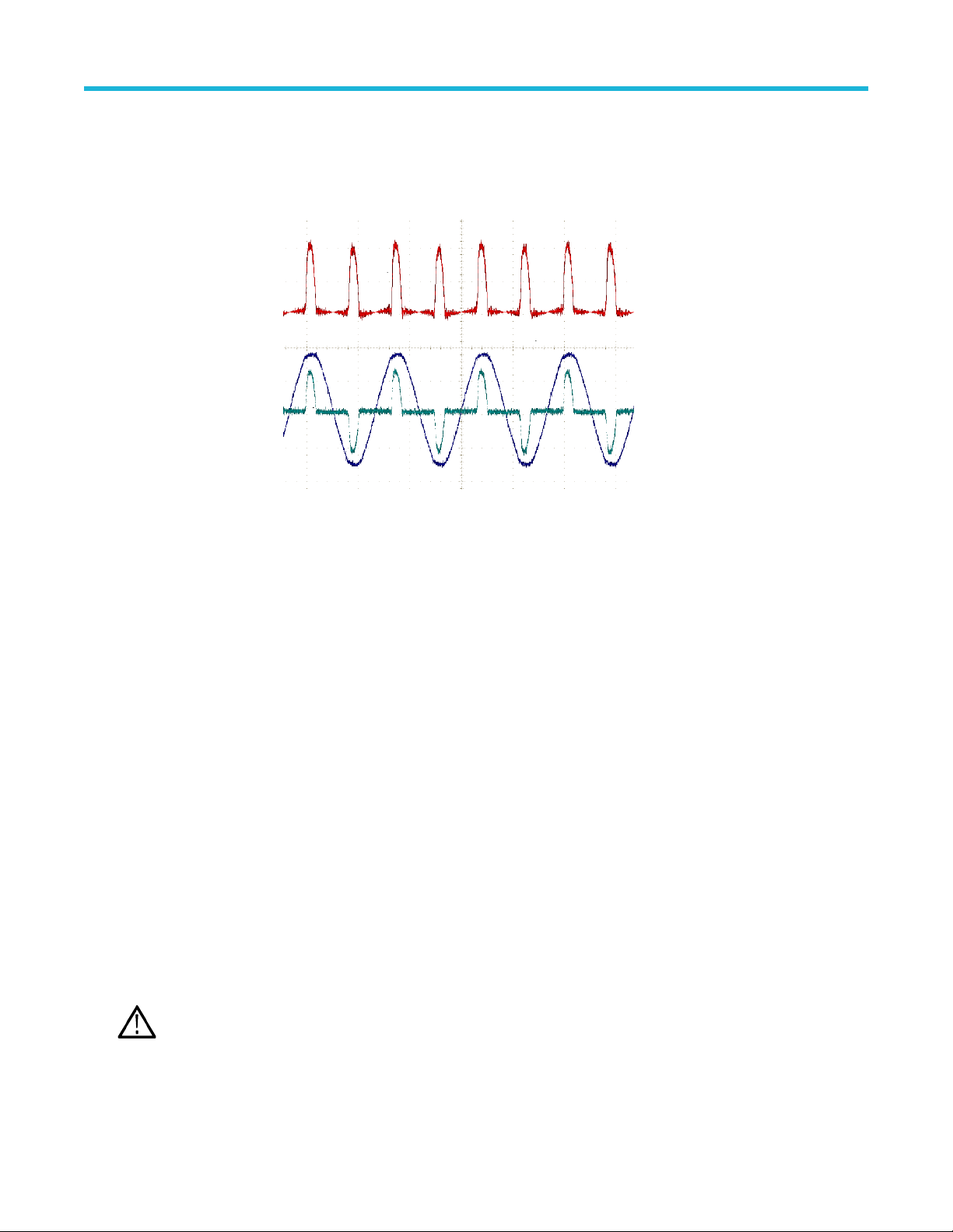
Multipurpose knob to change
the waveform scale.
Note that the math vertical
scale setting only applies to
the math waveform.
An example of using a math
waveform is to calculate
instantaneous power (current
times voltage) by multiplying
a voltage waveform and a
current waveform.
Analyzing a waveform
Math waveform tips
• Math waveforms get their horizontal scale and position from the sources channels. Adjusting these controls for the source waveforms
also adjusts the math waveform.
• Adding or subtracting waveforms with different units sets the math waveform units to “?”.
• You can take automatic measurements on math waveforms similarly as on channel waveforms. Just select the Math side menu in the
Measure screen and select the measurements to apply.
• You can save a math waveform to a reference memory or to a file on a USB drive. You can also recall (load) math waveforms into
reference memory. See Recalling waveform data on page 108.
• You can zoom in on math waveforms using the Navigation controls (Zoom button and Multipurpose knob).
Using FFT to see signal frequency information
There are many signals that have some sort of distortion or unwanted characteristics. Sometimes these distortions do not affect how
that signal works in the circuit. But often system clock pulses, signals induced from a nearby printed circuit path, or noise from a power
supply or other source can affect a signal and prevent it from operating correctly. The FFT function is a powerful tool to help you find the
frequencies of unwanted signals that are embedded in your main signal.
The FFT function uses Fast Fourier Transformation (FFT) mathematical calculations on the waveform data to determine the component
frequencies in the signal. The resulting waveform shows a series of ‘spikes’ along a horizontal axis, where each spike represents a
frequency component of the waveform and its amplitude. In other words, an FFT is a basic spectrum analyzer function to analyze
frequency components of a waveform.
1. Acquire and display several cycles of the waveform.
You can only display FFT waveforms for 2000 and 20K point record length waveforms.
Note:
2. Push FFT button.
TBS1000C Series Oscilloscopes User Manual 94
Page 95

Analyzing a waveform
The oscilloscope shows the default FFT screen. The lower main screen shows the FFT waveform.
Use the Vertical Position knob of the source channel to move the FFT waveform up or down.
3. Push Source wfm side-menu button to toggle the display of the source waveform (at the top of the screen) On or Off.
4. Push the Source side-menu button and use Multipurpose knob to set the source to channel 1 or 2.The default source is whatever
channel was selected before opening the FFT window.
5. Push the Vertical Units side-menu button and use the Multipurpose knob to select and click dBV RMS or Linear RMS.
Use the default dBV RMS Vertical Units scale to see a detailed view of multiple frequencies, even if the frequencies have very
different amplitudes.
TBS1000C Series Oscilloscopes User Manual 95
Page 96

Use the Linear RMS vertical scale to see an overall view of how all frequencies levels compare to each other.
Analyzing a waveform
6. Push the Window side-menu button and use the Multipurpose knob to select and click Hanning, Rectangular, Hamming, or
Blackman-Harris. See About FFT windows on page 98.
7. Push -More- Page 1/2 side-menu button.
8. Push the Horizontal Center Position side-menu button and use the Multipurpose knob to position the FFT graph horizontally. The
readout on the side menu is the frequency of the waveform point that is positioned on the center vertical graticule. Use this to quickly
measure FFT ‘spike’ frequencies.
TBS1000C Series Oscilloscopes User Manual 96
Page 97

Analyzing a waveform
9. Push the Horizontal Scale side-menu button and use the Multipurpose knob to set the horizontal scale (frequency per major
graticule division) value. Use this to expand or contract the FFT waveform to show more or less detail. The FFT waveform expands
around the center cursor.
10. Push the Cursors front-panel button and use the cursors to take measurements.
TBS1000C Series Oscilloscopes User Manual 97
Page 98

Analyzing a waveform
FFT tips
• You can only display FFT waveforms for 1000, 2000 and 20K record length waveforms.
• Use the Vertical Position knob of the source channel to change the vertical position of the FFT waveform.
• Use the Vertical Scale knob of the source channel to change the vertical size of the FFT waveform.
• Use cursors to measure frequencies and relative signal levels.
• Input signals that have a DC component or offset can cause incorrect FFT waveform component magnitude values. To minimize the
DC component, use AC Coupling on the input signal.
• To reduce random noise and aliased components See FFT and display waveform aliasing on page 100. in repetitive or single-shot
events, set the oscilloscope acquisition mode to average over 16 or more samples. Average mode attenuates signals not synchronized
with the trigger.
• Do not use the Average acquisition mode if the source signal contains frequencies of interest that are not synchronized with the trigger
rate.
• For transient (impulse, one-shot) signals, set the oscilloscope trigger conditions so that the transient pulse waveform is centered in the
waveform record.
About FFT windows
The FFT algorithm applies a ‘window’ process to the source waveform record to ‘shape’ the record so that the start and stop values for
the FFT waveform are close to the same amplitude. Starting and stopping the waveform at close to the same amplitude reduces adding
artificial waveform that are not present in the actual signal. Using a window on the source signal results in an FFT waveform that more
accurately represents the source signal frequency components.
TBS1000C Series Oscilloscopes User Manual 98
Page 99

Analyzing a waveform
The different window shapes are trade-offs between frequency accuracy and magnitude accuracy. What you want to measure, and your
source signal characteristics, help you to select which window to use. Use the following guidelines to select the best window for your signal
analysis needs. The Hanning window is a good starting point for FFT measurements.
Table 10: FFT windows
Window type Window ‘shape’
Hanning
This is a very good window for measuring amplitude accuracy but less so for resolving frequencies.
Use Hanning for measuring sine, periodic, and narrow band random noise. This window works on
transients or bursts where the signal levels before and after the event are significantly different.
Rectangular
This is the best type of window for resolving frequencies that are very close to the same value but worst for
accurately measuring the amplitude of those frequencies. It is the best type for measuring the frequency
spectrum of nonrepetitive signals and measuring frequency components near DC.
Use Rectangular for measuring transients or bursts where the signal level before and after the event are
almost equal. Also, use this window for equal-amplitude sine waves with frequencies that are very close,
and for broadband random noise with a relatively slow varying spectrum.
Hamming
This is a very good window for resolving frequencies that are very close to the same value with somewhat
improved amplitude accuracy over the rectangular window. It has a slightly better frequency resolution
than the Hanning.
Use Hamming for measuring sine, periodic, and narrow band random noise. This window works on
transients or bursts where the signal levels before and after the event are significantly different.
Table continued…
TBS1000C Series Oscilloscopes User Manual 99
Page 100

Analyzing a waveform
Window type Window ‘shape’
Blackman-Harris
This is the best window for measuring the amplitude of frequencies but worst at resolving frequencies.
Use Blackman-Harris for measuring predominantly single frequency waveforms to look for higher order
harmonics.
FFT and display waveform aliasing
FFT waveform problems occur when the oscilloscope acquires a signal that contains frequency components that are greater than the
Nyquist frequency (the Nyquist frequency is 1/2 of the sample rate). The frequency components that are above the Nyquist frequency are
undersampled and appear to "fold back," or reflect, around the right edge of the graticule, showing as lower-frequency components in the
FFT waveform. These incorrect components are called aliases.
You can use the following methods to reduce or eliminate aliases:
• Increase the sample rate by adjusting the Horizontal Scale front-panel knob to a faster frequency setting. Since you increase the
Nyquist frequency as you increase the horizontal sampling rate (samples/second), the aliased frequency components should appear at
their proper frequency. If the increased number of frequency components shown on the screen makes it difficult to measure individual
components, use the Horizontal Scale side-menu button in the FFT menu to display more detail of the FFT waveform.
• Use a filter on the input signal to limit the signal to frequencies below that of the Nyquist frequency. If the frequency components you
are interested in are below the built-in 20 MHz bandwidth setting, push the Vertical Menu button and set the channel bandwidth to
20 MHz.
Displaying reference waveforms
A reference waveform is a waveform that you have stored in a nonvolatile memory location on the oscilloscope. You can use a reference
waveform as a standard against which to compare other waveforms.
You can save channel, math, and FFT waveforms to reference memory. Reference waveforms remain in memory when the oscilloscope is
powered off.
See the Saving waveform data topic to learn how to save waveforms to reference memory or external files. See Saving waveform
data on page 105.
1. Push the Ref front-panel button.
TBS1000C Series Oscilloscopes User Manual 100
 Loading...