


TAP2500 and TAP3500
2.5 GHz and 3.5 GHz Probes
Instruction Manual
www.tektronix.com
071-1836-01

Copyright © Tektronix. All rights reserved. Licensed software products are owned by Tektronix or its subsidiaries or suppliers, and are protected by
national copyright laws and international treaty provisions.
Tektronix products are covered by U.S. and foreign patents, issued and pending. Information in this publication supersedes that in all previously
published material. Specifications and p rice change privileges reserved.
TEKTRONIX and TEK are registered trademarks of Tektronix, Inc.
TekVPI is a trademark of Tektronix, Inc.
Contacting Tektronix
Tektronix, Inc.
14200 SW Karl Braun Drive
P.O . Bo x 50 0
Beaverton, OR 97077
USA
For product information, sales, service, and technical support:
In North America, call 1-800-833-9200.
Worldwide, visit www.tektronix.com to find contacts in your area.

Warranty 2
Tektronix warrants that this product will be free from defects in materials and workmanship for a period of one (1) year from the date of shipment. If
any suc h product proves defective during this warranty period, Tektronix, at its option, either w ill repair the defective product without charge for parts
and labor, or will provide a replacement in exchange for the defective product. Parts, modules and replacement products used by Tektronix for
warranty work may be new or reconditioned to like new performance. All replaced parts, modules and products become the property of Tektronix.
In order to obtain service under this warranty, Customer must notify Tektronix of the defect before the e xpiration of the warranty period and make
suitable arrangements for the performance of service. Customer shall be responsible for packaging and shipping the defective product to the service
center designated by Tektronix, with shipping charges prepaid. Tektronix shall pay for the return of the product to Customer if the shipment is to a
location within the country in which the Tektronix service center is loca ted. Customer shall be responsible for paying all shipping charges, duties,
taxes, and any other charges for products returned t o any other locations.
This w arranty shall not apply to any defect, failure or damage caused by improper use or improper or inadequate maintenance and care. Tektronix
shall not be obligated to furnish service under this warranty a) to repair damage resulting from attempts by personnel other than Tektronix
representatives to install, repair or service the product; b) to repair damage resulting from improper use or connection to incompatible equipment; c) to
repair any damage or malfunction caused by the use of non-Tektronix supplies; or d) to service a product that has been modified or integrated with
other products when the effect of such modification or integration increases the time or difficulty of servicing the product.
THIS WARRANTY IS GIVEN BY TEKTRONIX WITH RESPECT TO THE PRODUCT IN LIEU OF ANY OTHER WARRANTIES, EXPRESS OR
IMPLIED. TEKTRONIX AND ITS VENDORS DISCLAIM ANY IMPLIED WARRANTIES OF MERCHANTABILITY OR FITNESS FOR A PARTICULAR
PURPOSE. TEKTRONIX’ RESPONSIBILITY TO REPAIR OR REPLACE DEFECTIVE PRODUCTS IS THE SOLE AND EXCLUSIVE REMEDY
PROVIDED TO THE CUSTOMER FOR BREACH OF THIS WARRANTY. TEKTRONIX AND ITS VENDORS WILL NOT BE LIABLE FOR ANY
INDIRECT, SPECIAL, INCIDENTAL, OR CONSEQUENTIAL DAMAGES IRRESPECTIVE OF WHETHER TEKTRONIX O R THE VENDOR HAS
ADVANCE NOTICE OF THE POSSIBILITY OF SUCH DAMAGES.


Table of Contents
Table of Contents
General Safety Sum m ary .. . ................................................................................................................ v
Environmental Considerations ............................................................................................................. ix
Preface...................................................................................................................................... xi
Documentation........................................................................................................................ xi
ConventionsUsed in this Manual .................................................................................................... xi
Returning theProbe for Servicing...................................................................................................xii
KeyFeatures ............................................................................................................................... 1
Installation .................................................................................................................................. 2
Connecting to the Host Instrument ................................................................................................... 2
Probe Controls andIndicators........................................................................................................ 3
Functional Check........................................................................................................................... 6
Required Equipment .................................................................................................................. 6
Calibration .................................................................................................................................. 8
Prerequisites.......................................................................................................................... 8
Required Equipment .................................................................................................................. 8
Test Procedure........................................................................................................................ 9
Basic Operation............................................................................................................................ 13
Probe Head Assembly...............................................................................................................13
Probe Input........................................................................................................................... 14
TAP2500 and TAP3500 Instruction Manual i

Table of Contents
Probe Offset.......................................................................................................................... 16
Accessoriesand Options.................................................................................................................. 19
Using Standard Accessories . .. ..................................................................................................... 19
OptionalAccessories ................................................................................................................ 29
Options ............................................................................................................................... 32
Probing Principles ......................................................................................................................... 33
Ground Lead Length .. ............................................................................................................... 33
Ground Lead Inductance .................................................................................................................. 34
Low-inductance Grounding. ............................................................................................................... 35
SureFoot™ Grounding . . .................................................................................................................. 36
Probe Tip Test Points...................................................................................................................... 37
Probe Tip Stabilization..................................................................................................................... 38
Specifications.............................................................................................................................. 39
Warranted Characteristics........................................................................................................... 40
Typical Characteristics............................................................................................................... 41
Nominal Characteristics ............................................................................................................. 46
Performance Verification .................................................................................................................. 47
Equipment Required ................................................................................................................. 47
Equipment Setup..................................................................................................................... 49
DC Gain Accuracy................................................................................................................... 50
Rise Time ............................................................................................................................ 53
ii TAP2500 and TAP3500 Instruction Manual

Table of Contents
Test Record .......................................................................................................................... 61
Maintenance............................................................................................................................... 63
Error Condition....................................................................................................................... 63
ReplacementParts .................................................................................................................. 63
Cleaning.............................................................................................................................. 64
Index
TAP2500 and TAP3500 Instruction Manual iii

Table of Contents
iv TAP2500 and TAP3500 Instruction Manual

General Safety Summary
General Safety Summary
Review the following safety precautions to avoid injury and prevent damage to this product or any products con nected to it.
To avoid potential hazards, use this product only as specified.
Only qualified personnel should pe rform service procedures.
While using this product, you may need to access other parts of a larger system. Read the s afety sections of the other component
manuals for warnings and cautions related to operating the system.
To Avoid Fire or Personal Injury
Connect and Disconnect Properly. Do not connect or disconnect probes or test leads while they are connected to a voltage
source.
Connect and Disconnect Properly. Connect the probe output to the measurement instrument before conn ecting the probe to the
circuit under test. Connect the probe reference lead to the circuit under test before connecting the probe input. Disconnect the probe
input a nd the probe reference lead from the circuit under test before disconnecting the probe from the measurement instrument.
Ground the Product. This product is ind irectly grounded through the grounding conductor of the mainframe power cord. To avoid
electric shock, the grounding conductor must be connected to earth ground. Before making connections to the input or output
terminals of the product, ensure that the product is properly grounded.
Observe All Terminal Ratings. To avoid fire or shock hazard, observe all ratings and markings on the product. Consult the
product manual for further ratings information before making connections to the product.
Connect the probe reference lead to earth ground only.
Do not apply a potential to any terminal, including the common terminal, that exceeds the maximum rating of that terminal.
TAP2500 and TAP3500 Instruction Manual v

General Safety Summary
Do Not Operate Withou t Covers. Do not operate this product with covers or panels removed.
Do Not Operate With Suspected Failures. If you s uspe ct that there is damage to this product, have it inspected by qualified
service personnel.
Avoid Exposed Circuitry. Do not touch exposed connections and components when power is present.
Do Not Operate in Wet/Damp Conditions.
Do Not Operate in an Explosive Atmosphere.
Keep Product Surfaces Clean and Dry.
vi TAP2500 and TAP3500 Instruction Manual

General Safety Summary
Terms in this Manual
These terms may appear in this manual:
WARNING. Warning statements identify conditions or practices that could result in injury or loss of life.
CAUTION. Caution statements identify conditions or practices that could result in damag e to this product or other property.
Symbols and Terms on the Product
These terms may appear on the product:
DANGER indicates an injury hazard immediately accessible as you read the marking.
WARNING indicates an injury hazard not immediately accessible as you read the marking.
CAUTION indicates a hazard to property including the product.
TAP2500 and TAP3500 Instruction Manual vii
General Safety Summary
The following symbols may appear on the product:
viii TAP2500 and TAP3500 Instruction Manual
Environmental Considerations
Environmental Considerations
This section provides information about the environmental impact of the product.
Product End-of-Life Handling
Observe the following guidelines when recycling an instrument or component:
Equipment Recycling. Production of this equipment required the extraction and use of natural resources. The equipment may
contain substances that could be harmful to the environment or human health if improperly handled at the product’s end of life. In
order to avoid release of such substances into the environment and to reduce the use of natural resources, we encourage you to
recycle this product in an appropriate system that will ensure that most of the materials are reused or recycled appropriately.
The symbol shown below indicates that this product complies with the European Union’s requirements according to Directive
2002/96/EC on w aste electrical and electronic equipment (WEEE). For information about recycling options, check the
Support/Service section of the Tektronix Web site (www.tektronix.com).
TAP2500 and TAP3500 Instruction Manual ix

Environmental Considerations
Restriction of Hazardous Substances
This product has been classified as Monitoring and Control equipment, and is outside the scope of the 2002/95/EC RoHS Directive.
This product is known to contain lead, cadmium, and hexavalent chromium.
x TAP2500 and TAP3500 Instruction Manual

Preface
Preface
This manual describes the installation and operation of the TAP2500 and TAP3500 active probes. Basic probe operations and
concepts are presented in this manual. The TAP2500 probe is used in all illustrations in this manual, unless noted otherwise. You
can access this document and other related information from the Tektronix Web site.
Documentation
To read about Use these documents
*
TAP2500 and TAP3500 Probes: First Time Operation, Functional Ch eck,
Operating Basics, Specifications, Performance Verification
Read this Instruction Manual.
In-depth oscilloscope operation, user interface help, GPIB commands Access the online help from the Help menu on
the host instrument.
*
To access the documentation that is installed on your instrument, click Start in the taskbar and select Programs > TekApplications .
Conventions Used in this Manual
The following icon is used throughout this manual to indicate a step sequence.
TAP2500 and TAP3500 Instruction Manual xi
Preface
Returning the Probe for Servicing
If your probe requires servicing, you must return the probe to Tektronix. If the original packaging is unfit for use or not available, use
the following packaging guidelines:
Preparation for Shipment
1. Use a corrugated cardboard shipping
carton having inside dimensions at
least one inch greater than the probe
dimensions. The box should have a carton
test strength of at least 200 pounds.
2. Put the probe into an antistatic bag or wrap
it to protect it from dampness.
3. Place the probe into the box and stabilize it
with light packing material.
4. Seal the carton with shipping tape.
5. Refer to Contacting Tektronix at the
beginning of this manual for the shipping
address.
xii TAP2500 and TAP3500 Instruction Ma nual
Key Features
Key Features
The TAP2500 and TAP3500 active probes enable you to make accurate measurements with minimal circuit loading from DC to
2.5 GHz and 3.5 GHz respectively, using oscilloscopes featuring the new Tektronix Te k VPI oscilloscope interface. Key features
include:
Bandwidth
DC to ≥2.5 GHz (TAP2500)
DC to ≥3.5 GHz (TAP3500)
±4 Volts Dynamic Range with ±10 volt
offset capability
10X Attenuation
40 kΩ Input Resistance
<0.8 pF Input Capacitance
TekVPI Interface
Small, low-mass probe head for probing
dense circuitry
TAP2500 and TAP3500 Instruction Manual 1
Installation
Installation
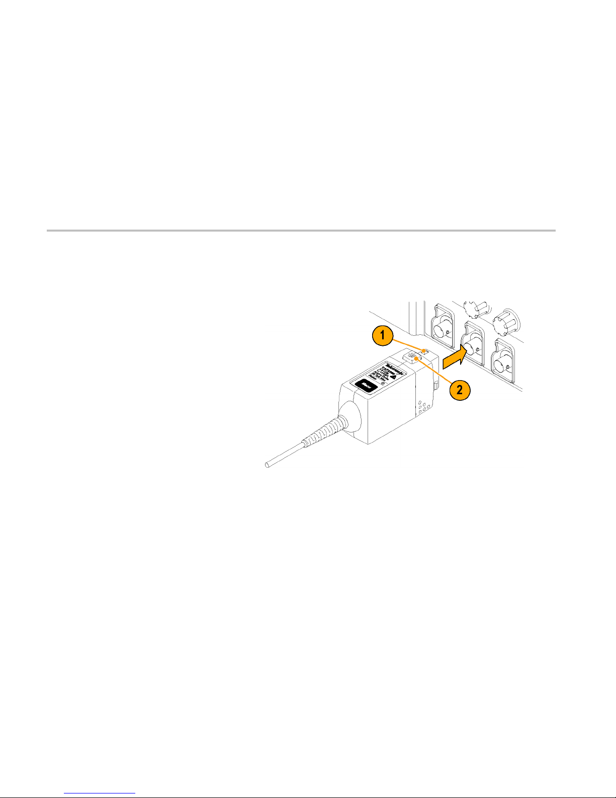
Connecting to the Host Instrument
1. Slide the probe into the TekVPI receptacle.
The probe snaps when fully engaged.
When the probe is connected, the host
instrument reads information from the
probe and identifies the device.
2. To disconnect, press the latch release
button and pull away from the instrument.
2 TAP2500 and TAP3500 Instruction Ma nual
Installation
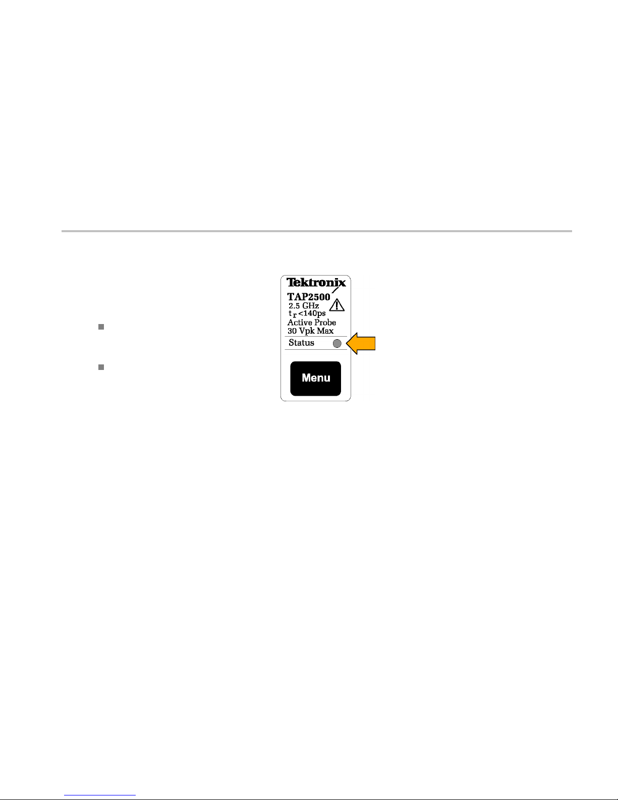
Probe Controls and Indicators
Status LED
When the probe is powered on, the multicolor
Status LED:
Glows green after successfully completing
the power-on self test rout ine. The probe is
in normal operating mode.
Glows red if an error condition exists. (See
page 63, Error Condition.)
TAP2500 and TAP3500 Instruction Manual 3
Installation
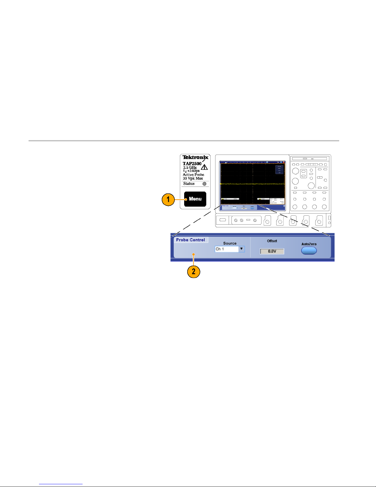
Menu Button
1. Press the probe Menu button to display the
Probe Control screen on the oscilloscope.
2. Use the touch-screen buttons on the
instrument to set the probe parameters.
3. Press the probe Menu buttonagainto
close the Probe Control screen.
4 TAP2500 and TAP3500 Instruction Ma nual
Installation
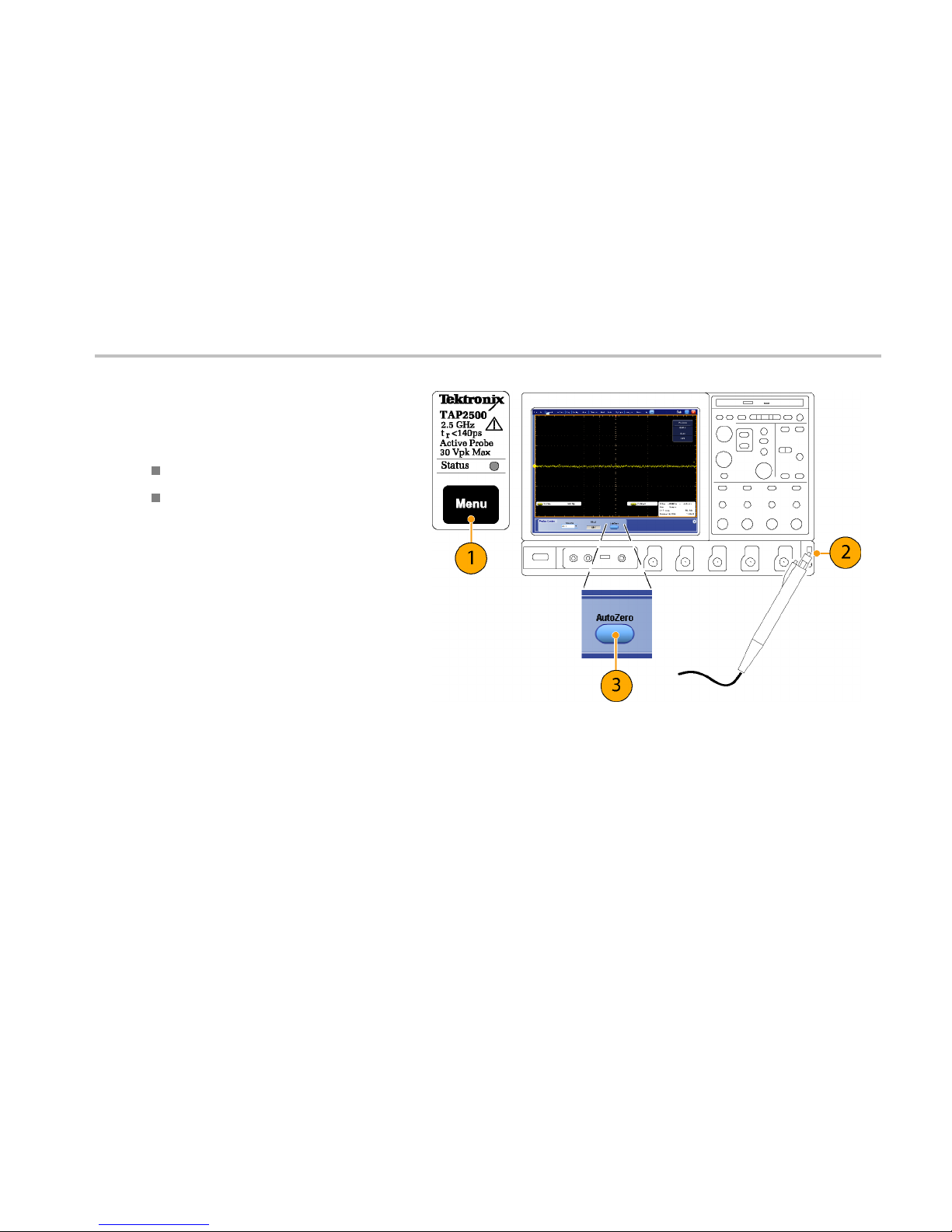
AutoZero
We recommend that you run the probe
AutoZero routine:
After the 20 minute warm-up period
When the operating temperature of the
probe changes by ±5 °C
1. Press the probe Menu button to display the
Probe C ontrol screen on the oscilloscope.
2. Short the probe tip to ground.
3. Press the AutoZero buttononthe
instrument to execute the AutoZero routine.
TAP2500 and TAP3500 Instruction Manual 5

Functional Check
Functional Check
Use the following procedure to check that your probe is functioning properly. If you want to verify that your probe meets the
warranted specifications, refer to the Performance Verification procedures. (See page 47.)
Required Equipment
Description and quantity Performance requirement Recommended example
1
Oscilloscope TekVPI Interface Tektronix DPO7000 Series
Y-Lead adapter
0.25-in square pins fo r probe tip
connections
196-3463-XX
2
SMT KlipChip adapters (2)
0.25-in square pins-to-mini clips 206-0364-XX
2
1
Nine-digit part numbers (xxx-xxxx-xx) are Tektronix part numbers.
2
Standard probe accessory
6 TAP2500 and TAP3500 Instruction Ma nual
Functional Check
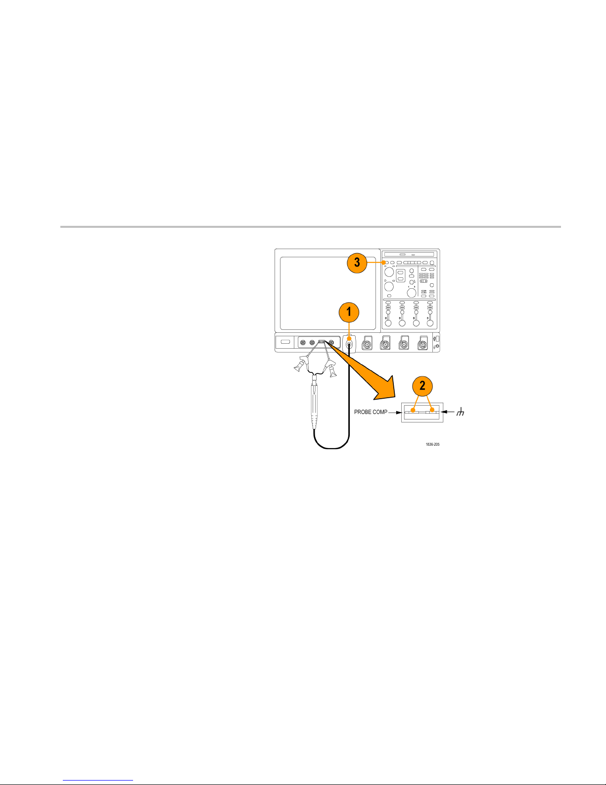
Signal
1. Connect the p robe to any channel of the
oscilloscope and set the oscilloscope to
display that channel.
2. Use the Y-lead Adapter and two SMT
KlipChips to connect the probe tip to
the PROBE COMP terminals on the
oscilloscope.
3. Press AUTOSET (or adjust the
oscilloscope) to d isplay the calibration
waveform. A stable waveform indicates
that your probe is functioning correctly.
TAP2500 and TAP3500 Instruction Manual 7

Calibration
Calibration
The probe calibration routine minimizes yo ur measurem ent errors by optimizing the gain and offset of the probe and oscilloscope
combination. We recommend that you repeat the probe calibration on each channel that you use. Individual calibration constants
are stored for each probe on each channel.
Prerequisites
The equipment must be warmed up for 20 minutes, and the calibration status of the host instrument must be pass.
Required Equipment
The r equired equipment for calibration is the same as for the functional check. (See page 6, Required Equipment.)
8 TAP2500 and TAP3500 Instruction Ma nual
Calibration
Test Procedure
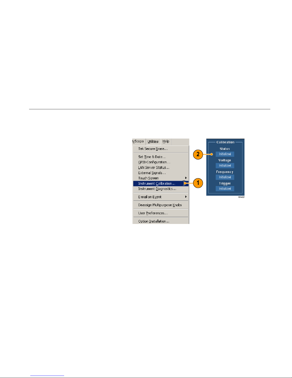
Check the Calibration Status of the instrument:
1. From the Utilities menu, select Instrument
Calibration.
2. In the Calibration box, check that Pass is
displayed in the Status field. If it is not,
disconnect all probes and signal sources
from the oscilloscope, and run the Signal
Path Compensation routine (see next step).
TAP2500 and TAP3500 Instruction Manual 9

Calibration
3. Connect the probe to the oscilloscope
PROBE COMP conn ector as shown.
4. From the Vertical menu, select Probe Cal.
10 TAP2500 and TAP3500 Instruction Manual

Calibration
5. When th e Probe Setup screen appears,
select Clear ProbeCal, and then select
Calibrate Probe.
The probe calibration routine begins. When
the routine completes, a notifier appears.
Close the notifier and begin using your
probe.
TAP2500 and TAP3500 Instruction Manual 11

Calibration
12 TAP2500 and TAP3500 Instruction Manual

Basic Operation
Basic Operation
Follow these operating guidelines to get optimum performa nce from your probe.
Probe Head Assembly
The probe head is de signed for ease of use
andhighperformance. Itssmallsizemakesit
easy to handle in tight areas.
1. The probe tip socket is sized to easily press
onto 0.025-inch pins fo r direct access.
2. The ground socket provides a short ground
path for high-fide lity ground connections.
3. The stabilization notch permits you to use
adjacent pins to reduce stresses on the
probe and pins.
TAP2500 and TAP3500 Instruction Manual 13

Basic Operation
Probe Input
The probe is electrically protected against static voltage. However, applying voltages above its design limits may damage the
probe tip amplifier. (See Figure 1 on page 15.)
Input Linear Dynamic Range
The probe head amplifier used by the probe has a limited linear operating range. To keep the inpu t linearity error less than 1% you
must limit the signal input voltage to ±4 V (including any DC offset).
14 TAP2500 and TAP3500 Instruction Manual

Basic Operation
Figure 1: Dynamic and Offset Limitations
TAP2500 and TAP3500 Instruction Manual 15

Basic Operation
Probe Offset
The probe offset is adjustable to permit operation within the linear range of the probe, and to increa se the sensitivity of the probe
at higher DC measurement voltages. Using the offset to cancel DC signal compon ents enables optimal probe performance.
(See Figure 1 on page 15.)
NOTE. See your oscilloscope manual for specific instructions on using the offset control.
To set the probe offset, follow these steps:
1. Use th e vertical position control to set a
zero reference level on the oscilloscope
display.
2. Set the oscilloscope coupling to DC and
5 V/div. This sets the oscilloscope to
display the full offset dynamic range of the
probe.
16 TAP2500 and TAP3500 Instruction Manual

Basic Operation
3. Attach the probe to the circuit.
4. Adjust the probe offset to bring the trace to
the oscilloscope zero reference.
5. Change the volts/division setting to the
desired range, adjusting t he offset to keep
the trace on the zero reference level.
NOTE. The probe has a ±10 V offset range. The linear operating range is ±4 V. (See Figure 1 on page 15.) If cursors are used on
the oscilloscope, the zero reference will be at the probe offset voltage. When you adjust the probe offset with no signal applied to
the probe input, the output range is ±4V, (the linear operating range of the probe), not the ±10V offset range of the probe. However,
when you apply ±10V to the probe input, the probe offset control is capable of zeroing this offset.
TAP2500 and TAP3500 Instruction Manual 17

Basic Operation
18 TAP2500 and TAP3500 Instruction Manual

Accessories and Options
Accessories and Options
This section lists the standard accessories and provides information on how to use the accessories. Specifications are provided
where appropriate so that you can choose the accessory that best fits your needs. In some cases, reorder kit quantities differ from
the actual number of accessories included with the probe.
Using Standard Accessories
Push-in Probe Tip
Use the push-in probe tip for general purpose
probing by hand. You can also use the push-in
probe tip with the other socketed leads and
adapters.
Push the tip into the socket until it is seated.
Either end of the tip may be used. Do no t force
the tip. Also, be careful not to injure yourself
on the sharp point.
Reorder Tektronix part number:
131-5638-11 qty. 10
TAP2500 and TAP3500 Instruction Manual 19

Accessories and Options
SureToe Adapter
The SureToe adapter is a pointed probe tip
useful for probing in dense circuitry. Attach the
SureToe adapters the same way as the push-in
probe tips.
Do not force the adapter. Also, be careful not to
poke yourself with the sharp probe tip. SureToe
adapters can be used with any of the socketed
accessory leads. Four Su reToe adap ters are
included with the probe.
Reorder Tektronix part number:
131-6254-XX qty. 4
20 TAP2500 and TAP3500 Instruction Manual

Accessories and Options
Pogo Pin Ground
Use the low-inductance ground pogo pin to
substantially reduce ground lead inducta nce
and t o easily move the probe to different points
on the circuit under test.
To attach, press the pogo pin into the probe
head ground socket. To maintain signal fidelity
while probing, use as short a ground path as
possible. (See page 33, Ground Lead Length.)
Reorder Tektronix part number:
016-1772-10 qty. 10
TAP2500 and TAP3500 Instruction Manual 21

Accessories and Options
Square Pin Socket
The square pin socket is ideal for use with
signal/ground pairs on 0.100-inch square
header pins. Attach the socket by gently
pressing it into the ground socket on the probe
head.
Be sure to use the stabilization notch whenever
possible to avoid slipping and damaging the
probe or circuitry under test.
Reorder Tektronix part number:
016-1773-10 qty. 10
Customizable Ground Lead
You can bend or shorten this ground lead.
Cut the tip of the ground lead wire at a 30° to
60° angle to ease insertion into the ground
socket of the probe.
To maintain signal fidelity while probing, use as
short a ground path as possible. (See page 33,
Ground Lead Length.)
Reorder Tektronix part number:
196-3482-XX qty. 5
22 TAP2500 and TAP3500 Instruction Manual

Accessories and Options
Right-Angle Adapter
Use the righ t-angle adapter for low-profile
probing of 0.025-inch square pins. The
right-angle adapter allows the probe to lie flat
against a circuit board, enabling you to probe
in tight areas such as between circuit cards.
The right-angle adapter can be used directly
with the probe head, or attached to the Y -lead
adapter or ground leads.
Attach the right-angle adapter the same way as
the push-in probe tip.
Reorder Tektronix part number:
016-1774-XX qty. 10
TAP2500 and TAP3500 Instruction Manual 23

Accessories and Options
Y-Lead Adapter and Ground Leads
Use the Y-lead adapter to extend the reach
of the probe and ground. The Y-lead adapter
accepts any of the probe tips or adapters, and
can be pushed directly onto 0.025 inch square
pins.
Use the ground leads for general,
lower-frequency probing. The socketed
end of the leads may be connected to any
of the probe tips and adapters, or fitted onto
0.025-inch square pins.
When selecting the grounding connection,
maintain as short a ground path as possible.
(See page 33, Ground Lead Length.)
Reorder Tektronix part number: 196-3456-XX
Kit includes:
Y-lead adapter, qty. 2
Three-in ground leads, qty. 3
24 TAP2500 and TAP3500 Instruction Manual

Accessories and Options
SMT KlipChip Adapter
Use the SMT KlipChip test clips to access
fragile, dense circuitry. KlipChip test clips can
be connected to the Y-lead or ground leads.
Simply press the lead socket into the KlipChip
handle.
The KlipChip body freely turns, allowing better
probe orientation. To reduce stress and provide
a lower profile on components being tested,
the flexible sleeve of the KlipChip bends up to
a 35° angle.
Reorder Tektronix part number:
206-0364-XX qty. 1
TAP2500 and TAP3500 Instruction Manual 25

Accessories and Options
Color Band Kit (Five Colored Pairs)
1. Attach one band to the probe cable and
another one of the same color n ear the
probe compensation box.
2. Connect the probe to the channel that
matches the color of the band.
Reorder Tektronix part number:
016-1315-XX qty. Set of 5 colors
Antistatic Wrist Strap
When using the probe, always work at an
antistatic work station and wear the antistatic
wrist strap.
Reorder Tektronix part number:
006-3415-XX
26 TAP2500 and TAP3500 Instruction Manual

Accessories and Options
Pouch, Nylon Carrying Case with
Inserts
Use the carrying case to hold the probe, the
accessories, and the instruction manual.
1. Place the probe, accessories, and manual
in the carrying case.
2. Close the carrying case to transp ort the
accessories to another location or for
storage.
Reorder Tektronix part number:
016-1952-XX
TAP2500 and TAP3500 Instruction Manual 27

Accessories and Options
Instruction Manual
The instruction manual provides instructions for
operating and maintaining the TAP2500 and
TAP3500 active probes. Store the instruction
manual in the probe case for easy reference.
Reorder Tektronix part number:
071-1836-XX (English)
071-1884-XX (Japanese)
071-1885-XX (S. Chinese)
28 TAP2500 and TAP3500 Instruction Manual

Accessories and Options
Optional Accessories
This section lists the optional accessories that you can purchase to help you with your probing tasks.
SureFoot™ Probe Tips
The SureFoot tips are an inte gral probe tip
and miniature guid e that enables fault-free
probing of fine-pitch SMD packages. A ttach
the SureFoot adapters the same way as the
push-in probe tips.
SureFoot tips are available in three sizes:
The yellow, 0.050-inch SureFoot tip is
compatible with 50 mil JEDEC packages such
as SOIC, PLCC, CLCC, etc.
Order Tektronix part number SF501 qty. 12
The blue, 0.025-inch SureFoot tip is compatible
with 0. 65 mm JEDEC and EIAJ packages.
Order Tektronix part number SF502 qty. 12
TAP2500 and TAP3500 Instruction Manual 29

Accessories and Options
The red, 0.5 mm SureFoot tip is comp atible
with EIAJ packages.
Order Tektronix part number SF503 qty. 12
IC Micro-Grabber
Use the IC Micro-Grabber to probe the leads
on integrated circuits that are surface-mounted.
Order Tektronix part number:
013-0309-XX qty. 2
SMA-to-Probe Tip Adapter
Use the adapter to connect the probe to SMA
cables and for calibration and performance
verification. The adapter includes a 50 Ω SMA
termination.
Order Tektronix part number: 015-0678-XX
30 TAP2500 and TAP3500 Instruction Manual

Accessories and Options
TekVPI Calibration Fixture
The calibration fixtureisrequiredtodoa
performance verification on the probe. It
provides an SMA connector in the probe signal
path for internal probe measurement s.
Order Tektronix part number: 067-1701-XX
TAP2500 and TAP3500 Instruction Manual 31

Accessories and Options
Options
Service Options
Option CA1. Provides coverage for a single Calibration Event
Option C3. Calibration Service 3 years
Option C5. Calibration Service 5 years
Option D1. Calibration Data Report
Option D3. Calibration Data Report, 3 years (with Option C3)
Option D5. Calibration Data Report, 5 years (with Option C5)
Option R3. Repair Service 3 years
Option R5. Repair Service 5 years
Manual Options
Option L0. English language Instruction Manual
Option L5. Japanese language Instruction Manual
Option L7. Simplified Ch inese language Instruction Manual
32 TAP2500 and TAP3500 Instruction Manual

Probing Principles
Probing Principles
Follow these helpful hints to make probing easier and noise free.
Ground Lead Length
When you are probing a circuit, you should
always use as short a ground lead as possible
between the probe head and circuit ground.
(See the illustration for the effects of lead length
on waveform distortion.)
The series inductance added by the probe tip
and ground lead can result in a resonant circu it;
this circuit may cause parasitic ringing within
the bandwidth of your oscilloscope.
TAP2500 and TAP3500 Instruction Manual 33

Ground Lead Inductance
Ground Lead Inductance
When you touch your probe tip to a circuit element, you are introducing a new resistance, capacitance , and ind uctance into the
circuit.
You can determine if ground lead effects may
be a problem in your application if you know
the self-inductance (L) and capacitance (C)
of your probe and ground lead. Calculate the
approximate resonant frequency (f
0
)atwhich
this parasitic circuit will resonate with the
following formula:
The equation shows that reducing the ground
lead inductance will raise the resonant
frequency. If your measurements are affected
by ringing, your goal is to lower the inductance
of your ground path until the resulting resonant
frequency is well above the frequency of your
measurements.
The low-inducta nce ground contacts described
in Accessories can help you reduce the
effects of ground lead inductance on your
measurements.
34 TAP2500 and TAP3500 Instruction Manual

Low-inductance Grounding
Low-inductance Grounding
Use a ground plane on the package to m ake
probing the package easier, and to avoid
adding unnecessary ground lead length and
distortion:
1. Attach a small piece of copper clad on top
of the package.
2. Connect the copper clad to the package
ground connection.
3. Use the low-inductance ground lead to
keepthegroundleadlengthasshortas
possible.
Quick Tip
This method is very useful when making many
measurements on the same package.
TAP2500 and TAP3500 Instruction Manual 35

SureFoot™ Grounding
SureFoot™ Grounding
If you cannot use the low-inductance grounding
method recommended, the probe may be
grounded to the package under test using a
SureFoot adapter.
1. Connect a short ground lead to the probe.
2. Attach a SureFoot adapter at the end of
the ground lead.
3. Connect the Sure Foot adapter directly to
the package ground.
This method is preferred over using an adjacen t
circuit ground because it is the shortest ground
path possible.
36 TAP2500 and TAP3500 Instruction Manual

Probe Tip Test Points
Probe Tip Test Points
The push-in probe tip or a 0.025-inch square
pin can be soldered into a circuit to be used as
a temporary test point:
1. Solder the tip onto a lead or pin with a
low-power soldering iron.
2. Press the probe head onto the tip to make
a measurement.
3. Pull the probe head off when you are done.
Quick Tip
The probe tip m ay b e removed and reused by
desoldering it from the circuit, and soldering it
into another circuit in the future.
NOTE. Do not use pieces of solid-core copper wire as test points. If the wire breaks off in the probe tip socket, it may be impossible
to remove the wire, and it will prevent insertion of other accessory tips.
TAP2500 and TAP3500 Instruction Manual 37

Probe Tip Stabilization
Probe Tip Stabilization
The probe head has a stabilizing notch for use
with 0.100 inch-spaced header pins:
1. Press the probe onto the header pin.
2. Insert the stabilizing notch of the probe
onto an adjacent pin. This prevents
unnecessary force from being applied
directly to the probe tip or pins.
The signal-ground adapter can rest on the
stabilized pin without a risk of its moving
outofplace.
38 TAP2500 and TAP3500 Instruction Manual

Specifications
Specifications
The specifications are valid under the following conditions:
The probe has been calibrated at an ambient tempe rature of 23 °C ±5 °C.
The probe is connected to a host instrument with an input imped ance of 50 Ω .
The probe and oscilloscope must have a warm-up period of at least 20 minutes and be in an environment that does no t
exceed the limits described. (See Table 1.)
The Signal Path Compensation (SPC) has been run on the oscilloscope prior to testing the probe specifications.
Specifications for the TAP2500 and TAP3500 active probes fall into thre e categories: warranted, typical, and nominal characteristics.
TAP2500 and TAP3500 Instruction Manual 39

Specifications
Warranted Characteristics
Warranted characteristics describe guaranteed performance within tolerance limits or certain type-tested requirements. Warranted
characteristics that have checks in the Performance Verification section are marked with the
symbol. The Warranted, Typical,
and Mechanical characteristics apply to the TAP2500 and the TAP3500, probes unless noted otherwise.
Table 1: Warranted electrical characteristics
Characteristic Description
DC a ttenuation accuracy (probe only)
10:1 ±2% (excludes offset error)
Rise time (probe only)
≤140 ps (TAP2500)
≤130 ps (TAP3500)
Temperature
Operating: 0 to + 50 _C (+32 to +122 °F), Nonoperating: -40 to +71 °C (-40 to
+160 °F)
Humidity
Operating: 5-95% RH, tested up to +30 °C (+86 °F) 5-85% RH, tested at +30 °C to
+50°C(+86to+122°F)
Nonoperating: 5-95% RH, tested up to +30 °C (+86 °F ) 5-85% RH, tested a t
+30 °C to +75 °C (+86 to +167 °F)
Altitude
Operating: Up to 3000 meters (9,843 feet),
Nonoperating: Up to 12,000 meters (39,370 feet)
40 TAP2500 and TAP3500 Instruction Manual

Specifications
Typical Characteristics
Typical characteristics describe typical but not guaranteed performance.
Table 2: Typical electrical characteristics
Characteristic Description
Bandwidth (probe only) DC to ≥2.5 GHz (TAP2500)
DC to ≥3.5 GHz (TAP3500)
Input resistance
40 kΩ
Input capacitance ≤0.8 pF
Input signal range -4.0 V to +4.0 V
Input offset range
-10.0 V to +10.0 V
Output Zero
±10 mV or less displayed on screen
Maximum non destructive input voltage ±30 V
(DC + peak AC)
Linearity
±0.1% or less over a dynamic range of -3.75 V to +3.75 V ±1.0% or less over a
dynamic range of -4.0 V to +4.0 V.
DC offset drift 1.5 mV/ °C or less displayed on screen
Signal delay
5.3 ns ±0.2 ns
TAP2500 and TAP3500 Instruction Manual 41

Specifications
Figure 2: TAP2500 Typical bandwidth
42 TAP2500 and TAP3500 Instruction Manual

Specifications
Figure 3: TAP3500 Typical bandwidth
TAP2500 and TAP3500 Instruction Manual 43

Specifications
Figure 4: Typical input impedance and phase versus frequency
44 TAP2500 and TAP3500 Instruction Manual

Specifications
Table 3: Typical mechanical characteristics
Characteristic Description
Dimensions, compensation box
107mm×41mm×26mm(4.2in×1.6in×1.0in)
Dimensions, probe head
19.43 mm × 3.30 mm × 7.6 mm (0.765 in × 0.130 in × 0.300 in)
Dimensions, cable length
1.3 m (51 in) (from the probe head to the compensation box)
Unit weight
1.55 kg (3.44 lbs) (probe, accessories and packaging)
TAP2500 and TAP3500 Instruction Manual 45

Specifications
Nominal Characteristics
Nominal characteristics describe guaranteed traits, but the traits do not have tolerance limits.
Table 4: Nominal electrical characteristics
Characteristic Description
Input coupling
DC
Term i n atio n
Terminate output into 50 Ω
Compatibility Oscilloscopes equipped with the TekVPI interface
Pollution Degree 2, Indoor use only
46 TAP2500 and TAP3500 Instruction Manual

Performance Verification
Performance Verification
The procedures that follow verify the warranted specifications of the probe. The recommended calibration interval is one year.
Perform the verification procedures in the order listed.
Equipment Required
The following equipment is required for the performance verification procedures.
Table 5: Test equipment
Description and quantity Performance requirement Recommended example
1
Oscilloscope TekVPI Interface Tektronix DPO7000 Series
Sampling oscilloscope ≥12.5 GHz bandwidth Tektronix TDS8000 Series
Sampling module ≥12.5 GHz bandwidth
Tektronix 80E0X
Sampling module
TDR output: 250 mV step, <30 ps rise
time
Tektronix 80E04
TekVPI Calibration/Verification adapter TekVPI Interface
067-1701-XX
DC voltage source -1.0 to +1. 0 VDC, 0.2% accuracy
Wavetek 9100
Digital multimeter (DMM) Resistance, 0.1% accuracy
Keithley 2700
HF Probe Tip adapter
Probe tip adapter with 50 Ω termination
015-0678-00
SMA M-to-BNC F adapter SMA male-to-BNC female
015-0554-00
TAP2500 and TAP3500 Instruction Manual 47

Performance Verification
Table 5: Test equipment (cont.)
Description and quantity Performance requirement Recommended example
1
BNC-to-dual banana adapter (2)
103-0090-00
BNC cable 50 Ω , 0.76 m (30 in) length
012-0117-00
SMA cable (2) Male-to-Male SMA cable
012-0649-00
Precision termination
50 Ω ,0.1%,0.5W
011-0129-00
Y-Lead adapter
0.25-in square pins fo r probe tip
connections
196-3463-xx
2
SMT KlipChip adapters (2)
0.25-in square pins-to-mini clips 206-0364-xx
2
SMA torque wrench 5/16-in, 7 in-lb.
SMA adapter wrench 7/32-in
1
Nine-digit part numbers (xxx-xxxx-xx) are Tektronix part numbers.
2
Standard accessories included with the probe.
48 TAP2500 and TAP3500 Instruction Manual

Performance Verification
Equipment Setup
Use the following procedure to set up and warm up the equipment to test the probe.
1. Turn on the TekVPI oscilloscope.
2. Connect the TekVPI Calibration/Verification
adapter to the oscilloscope.
3. Connect the prob e to the TekVPI
Calibration/Verification ada pter and verify
that the Status LED on the probe turns
green.
4. Turn on the remaining test equipm ent.
5. Allow 20 minutes for the equipment to
warm up.
6. Photocopy the test record and use it to
record the test results. (See page 61, Te st
Record.)
TAP2500 and TAP3500 Instruction Manual 49

Performance Verification
DC Gain Accuracy
This test checks the DC gain accuracy of the probe.
1. Connect the BNC-to-dual banana adapter
to the DMM input.
2. Connect the SMA M-to-BNC F adapter
to the SMA output of the TekVPI
Calibration/Verification adapter.
3. Connect the precision termination to the
BNC end of the SMA M-to-BNC F adapter.
4. Connect the BNC cable between th e
precision termination and the BNC-to-dual
banana adapter attached to the DMM.
50 TAP2500 and TAP3500 Instruction Manual

Performance Verification
5. Connect the second BNC-to-dual banana
adapter to the output of the DC voltage
source.
6. Connect the Y-lead adapter and K lipChip
adapters to the probe input.
7. Attach the KlipChip adapters to the
BNC-to-dual banana adapter connected
to the DC voltage source. Make sure the
polarity is correct-ground to outer shield
and probe input to center conductor.
TAP2500 and TAP3500 Instruction Manual 51

Performance Verification
8. Set oscilloscope offset to 0.0 V.
9. Set the DMM to DCV.
10. PresstheREL(relative)buttontoZerothe
DMM.
11. Set the DC voltage source t o + 1.00 VDC
and enable the output.
12. Record the DMM measurement in the test
record.
13. Set the DC voltage source to -1.00 VDC.
14. Record the DMM measurement in the test
record.
NOTE. An unacceptable error value may
result if a precision 50 Ω termination is not
used for the recommended term ination, or if
the o scilloscope offset is not set to zero.
15. Leave the TekVPI Calibration/Verification
adapter and probe connected the
oscilloscope to keep the probe warm.
52 TAP2500 and TAP3500 Instruction Manual

Performance Verification
Rise Time
This procedure verifies that the probe meets the rise time specification. Two rise times are measured; the test system alone, and
then the test system with the probe included. The probe rise time is calculated using the two m easurements.
This test uses the TDR function of the 80E04 sampling head as a fast rise t ime signal source. A second 80E0X sampling head
is used to take the measurements. Although the following procedure assigns the TDR and measurement functions to specific
oscilloscope cha nnels, any channels can be used. However, the TDR function is only available on 80E04 sampling heads.
CAUTION. To prevent damage, use care when working with SMA connectors: support equipment to avoid mechanical strain on
the connectors, and when tightening connections, use a torqu e wrench to 7.5 in-lbs.
TAP2500 and TAP3500 Instruction Manual 53

Performance Verification
Test System Rise Time
1. Connect the 80E04 sampling head to
Channel1 of the sampling oscilloscope.
2. Connect the 80E0X sampling head to
Channel8 of the sampling oscilloscope.
3. Connect SMA cables to Channels 1 and 8.
4. Connect the SMA cable from Channel 1 to
the HF Probe Tip adapter.
54 TAP2500 and TAP3500 Instruction Manual

Performance Verification
5. Remove the 50 Ω termination from t he HF
Probe Tip adapter and connect the SMA
cable from Channel 8 to the adapter.
6. Turn on Channel 8 and set the vertical
scale to 50 mV/div.
TAP2500 and TAP3500 Instruction Manual 55

Performance Verification
7. Set the Channel 1/2 sampling head to TDR
mode: Press the SETUP DIALOGS button
and select the TDR tab.
8. Set the Channel 1 (C1) Polarity to positive
(rising).
9. Set the Preset of Channel 1 on.
TDR Preset sets Internal Clock in the
Trigger menu, turns on the TDR Step in the
TDR Setups menu, turns on the channel
and selects the acquisition Units in the
TDR Setups menu, and sets the horizontal
scale, position, and reference.
The sampling module will turn on a red
light next to the SELECT channel button,
indicating that TDR is activated for that
channel.
56 TAP2500 and TAP3500 Instruction Manual

Performance Verification
10. Turn off the display for Channel 1 so that
only Channel 8 is shown on screen.
11. Adjust the oscilloscope horizontal and
vertical position controls to display a signal
similar to that shown.
12. Set the oscilloscope horizontal scale to
50 ps/div and cente r the waveform.
NOTE. Do not touch the HF Probe Tip adapter
when making calibration measurements.
Measurement accuracy is degraded when the
probe tip adapter is handled.
13. Use the oscilloscope measurement
capability to display rise time. Increase the
stability of the pulse edge measurement
by using averaging, if ava ilable. Rise time
is determined from the 10% and 90%
amplitude points on the waveform. Record
therisetimeast
s
.
TAP2500 and TAP3500 Instruction Manual 57
Performance Verification
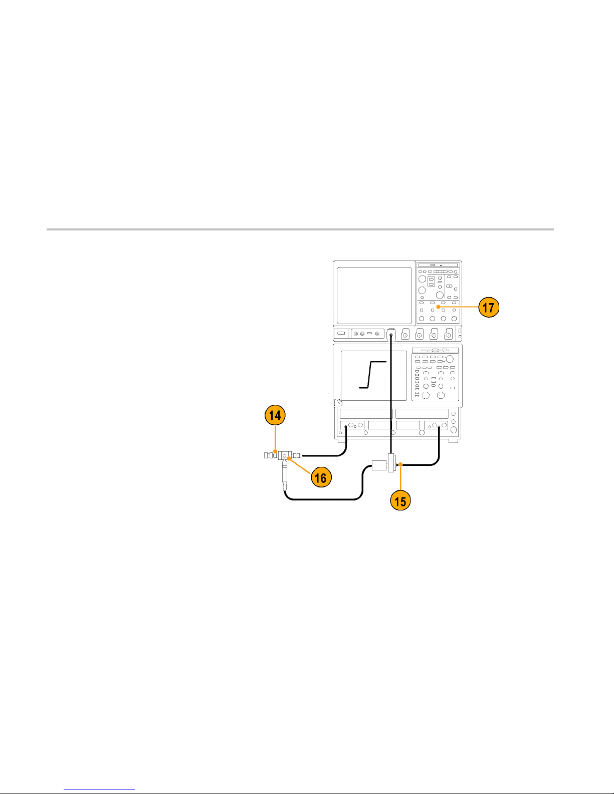
Test System and Probe Rise Time
14. Disconnect the SMA cable from the
Channel-8 side of the HF Probe Tip
adapter and reconnect the 50 Ω SMA
termination to the adapter.
15. Connect the SMA cable from Channel 8
of the sampling oscilloscope to
the S MA connector on the TekVPI
Calibration/Verification adapter.
16. Connect the probe to the HF Probe Tip
adapter.
17. Set the TekVPI oscilloscope offset to 0.0 V.
58 TAP2500 and TAP3500 Instruction Manual

Performance Verification
NOTE. The following measurements are taken
with the sampling oscilloscope. The TekVPI
oscilloscope only provides power and offset to
the probe.
18. On the sampling oscilloscope, expand
the horizontal scale to locate the step
edge: Set the vertical scale to 5 mV/div,
and adjust horizontal range to 100 ps/div
while maintaining the edge view. For a
more stable measurement display, turn
averaging on.
NOTE. Do not touch the HF Probe Tip adapter
when making calibration measurements.
Measurement accuracy is degraded when the
probe tip adapter is handled.
TAP2500 and TAP3500 Instruction Manual 59

Performance Verification
19. Adjust the position controls on the sampling
oscilloscope to display the entire leading
edge waveform.
20. Use the measurement capability of the
sampling oscilloscope to display rise
time: Increase the stability of the pulse
edge measurement by using averaging,
if available. Risetime is determined from
the 10% and 90% amplitude points on the
waveform. Record the rise time as t
s+p
.
21. Using the test system rise time (ts) that
you measured in step 13, and the test
system and probe rise time (t
s+p
) that
youmeasuredinstep20,calculatethe
probe-only rise time using the formula
shown.
22. Check that the calculated rise time meets
the probe specification.
23. Record the results on the test record.
Example:
60 TAP2500 and TAP3500 Instruction Manual

Performance Verification
Test Record
Probe Model/Serial N umber: Certificate Number:
Temperature:
RH %:
Date of Calibration:
Technician:
Performance test Source voltage
Minimum Measured
Calculated
Maximum
+1.00 VDC
+98 mV NA +102 mV
DC Gain Accuracy
-1.00 VDC
-102 mV NA -98 mV
Rise Time
(TAP2500)
(TAP3500)
NA
NA
NA
NA
NA
NA
140 ps
130 ps
TAP2500 and TAP3500 Instruction Manual 61

Performance Verification
62 TAP2500 and TAP3500 Instruction Manual

Maintenance
Maintenance
This section contains maintenance information for your probe.
Error Condition
The TAP2500 and TAP3500 active probes are designed to work with all TekVPI-interface oscilloscopes and adapters. However,
there may be some cases where all of the probe f eatures may not work properly.
If the Status LED glows red during or after probe power on, an internal probe diagnostic fault exists. Disconnect and reconnect the
probe to restart the power-on diagnostic sequence. If the Status LED continues to glow red, the probe is defective, and must
be returned to Tektronix for repair.
Replacement Parts
There are no user replaceable parts within the probe. Refer to Accessories for a list of replaceable accessories for your probe.
TAP2500 and TAP3500 Instruction Manual 63

Maintenance
Cleaning
Protect the probe from adverse weather conditions. The probe is not waterproof.
CAUTION. To prevent damage to the probe, do not expose it to sprays, liquids, or solvents. Avoid getting moisture inside
the probe during exterior cleaning.
Do not use chemical cleaning agents; they may dama ge the probe. Avoid using chemicals that contain benzine, benzene,
toluene, xylene, acetone, or similar solvents.
Clean the exterior surfaces of the probe with a dry, lint-free cloth or a soft-bristle brush. If dirt remains, use a soft cloth or swab
dampened with a 75% isopropyl alcohol solution. A swab is useful for cleaning narrow spaces on the probe, use only enough
solution to dampen the swab or cloth. Do not use abrasive compounds on any part of the probe.
64 TAP2500 and TAP3500 Instruction Manual

Index
Index
A
Accessories
optional, 29
standard, 19
AutoZero, 5
C
Calibration, 8
Cleaning the probe, 64
Connecting the probe, 2
D
DC gain accuracy
performance check, 50
Documentation, xi
E
Error condition, 63
F
Features, 1
Functional check, 6
G
Ground lead
inductance, 34
selecting length, 33
I
Indicators, 3
L
LED
Status, 3
M
Maintenance, 63
Menu Button, 4
O
Offset, 16
Options, 32
P
Performance verification, 47
equipment required, 47
equipment setup, 49
Probe controls and indicators, 3
Probe head, 13
R
Related documentation, xi
Replacement parts, 63
Rise Time
performance check, 53
S
Safety Summary, v
Signal path compensation, 9
Specifications, 39
nominal, 46
typical, 41
warranted, 40
Status LED, 3, 63
TAP2500 and TAP3500 Instruction Manual 65

Index
T
TekVP I , 2
Test record, 61
66 TAP2500 and TAP3500 Instruction Manual
 Loading...