

Page 1

Switch Matrix
Printable Application Help
*P077134601*
077-1346-01
Page 2

Page 3

Switch Matrix
Printable Application Help
www.tek.com
077-1346-01
Page 4

Copyright © Tektronix. All rights reserved. Licensed software products are owned by Tektronix or its subsidiaries
or suppliers, and are protected by national copyright laws and international treaty provisions. Tektronix products
are covered by U.S. and foreign patents, issued and pending. Information in this publication supersedes that in all
previously published material. Specifications and price change privileges reserved.
TEKTRONIX and TEK are registered trademarks of Tektronix, Inc.
Contacting Tektronix
Tektronix, Inc.
14150 SW Karl Braun Drive
P.O. Box 500
Beaverton, OR 97077
USA
For product information, sales, service, and technical support:
■
In North America, call 1-800-833-9200.
■
Worldwide, visit www.tek.com to find contacts in your area.
Page 5

Table of Contents
Welcome ............................................................................................................................................. iii
Getting help and support
Conventions used in help ................................................................................................................ 1
Related documentation ................................................................................................................... 1
Technical support ........................................................................................................................... 2
Getting started
Minimum system requirements ...................................................................................................... 3
Downloading and installing the application ................................................................................... 4
Purchase the license ........................................................................................................................ 4
Activate the license ......................................................................................................................... 5
View the software version .............................................................................................................. 5
Status indicators .............................................................................................................................. 6
File name extensions ...................................................................................................................... 6
Operating basics
Launch the application .................................................................................................................... 7
Application overview ..................................................................................................................... 9
Saved configurations .................................................................................................................... 16
De-embed settings ........................................................................................................................ 17
Apply a filter file for all relays ................................................................................................ 17
Apply a filter file for each relay type separately ..................................................................... 18
Apply a filter file for each relay separately ............................................................................. 18
Apply a filter file for each connection separately ................................................................... 19
Graphical view of switch matrix configuration ............................................................................ 20
Saving the configuration ............................................................................................................... 20
Feature description ....................................................................................................................... 21
Configure new switch .............................................................................................................. 21
Link width ............................................................................................................................... 26
Debug mode ............................................................................................................................ 26
Cascade (Relay cascade) ......................................................................................................... 27
Tutorial
Gigatronics switch configuration with cascade settings ............................................................... 31
Switch Matrix application help i
Page 6

Table of Contents
Create a new configuration (four lane, two SP4T relays) ............................................................ 32
Configure the filter file for each relay separately ......................................................................... 33
Debug the Keithley S46T switch .................................................................................................. 34
SCPI commands
About SCPI commands ................................................................................................................ 35
Socket configuration for SCPI commands ................................................................................... 35
SWITCH:*IDN ............................................................................................................................. 42
SWITCH:*OPC ............................................................................................................................ 42
SWITCH:CONFIG ....................................................................................................................... 43
SWITCH:DE-EMBED:ALL:FILTER_FILE ............................................................................... 43
SWITCH:DE-EMBED:CONN:FILTER_FILE ............................................................................ 44
SWITCH:DE-EMBED:FILTER_FILE ........................................................................................ 45
SWITCH:DE-EMBED:MODE .................................................................................................... 46
SWITCH:DE-EMBED:RELAY:FILTER_FILE .......................................................................... 46
SWITCH:DE-EMBED:RELAY_TYPE:FILTER_FILE .............................................................. 47
SWITCH:LASTERROR .............................................................................................................. 47
SWITCH:LINKWIDTH ............................................................................................................... 48
SWITCH:RELAY:CASCADE ..................................................................................................... 49
SWITCH:RELAY:CASCADED .................................................................................................. 50
SWITCH:RELAY:COMMON ..................................................................................................... 50
SWITCH:RELAY:POLARITY .................................................................................................... 51
SWITCH:RELAY:SIGNAL ......................................................................................................... 52
Reference
Error messages .............................................................................................................................. 53
ii Switch Matrix application help
Page 7

Welcome
Switch Matrix is a software solution which simplifies the user experience to
configure and setup automated multi-lane testing using RF switch. The solution
allows you to map each of the several transmitter signals and forward the selected
input either to another relay or to the oscilloscope channel.
Key Features:
■
Auto Detects Keithley and Gigatronics switches on the GPIB/LAN
interfaces.
■
De-embed using filter files with multiple de-embed options.
■
Apply single filter file for all relays, for each relay type separately, for each
relay separately, and for each connection separately.
■
Ability to cascade multiple relays within a switch.
■
Operates with TekExpress and DPOJET (Debug Mode)
■
Use standard built-in configurations or create custom configurations
■
Save/recall configurations
■
Graphical view with print option to support hardware wiring
■
Built in error handling to support easy and error-free configuration.
■
Programmatic interface to support scripting and easy integration into the
user’s automation environment.
Debug Mode:
■
Debug mode to manually close each relay channel.
■
Ability to close multiple contacts on a relay
■
Built-in Self-Test with report in .csv file
Switch Matrix application help iii
Page 8

Welcome
Status Indicators:
■
Status indicators for each relay signal being de-embedded
■
Status indicator for input displaying open or close relay contacts
■
Live status for Self-Test
iv Switch Matrix application help
Page 9

Getting help and support
Conventions used in help
This help uses the following conventions:
■
The terms "Application" and "Software" refer to the Switch Matrix
application.
■
The term “select” is a generic term that applies to the two methods of
choosing a screen item (button, control, list item): using a mouse or using the
touch screen.
■
The term "close" refers to normally close the relay signal (select the signal).
■
The term "open" refers to normally open the relay signal (unselect the
signal).
■
The term "channel" refers to the relay signal or oscilloscope channel.
Related documentation
The following documentation is available as part of the Switch Matrix
application.
Table 1: Product documentation
Item Purpose Location
Help Application operation
and User Interface help
PDF of the help Printable version of the
compiled help
PDF of the TekScope
Application User
Manual
Activate the license
www.tek.com
®
Switch Matrix application help 1
Page 10

Getting help and support
Technical support
Tektronix values feedback on our products. To help us serve you better, please
send us your suggestions, ideas, or comments on your application or oscilloscope.
Contact Tektronix through mail, telephone, or the Web site.
When you contact Tektronix Technical Support, please include the following
information (be as specific as possible):
■
Software version number
■
Description of the problem so that technical support can duplicate the
problem
■
If possible, save the setup files for all the instruments used and the
application.
2 Switch Matrix application help
Page 11

Getting started
Minimum system requirements
The following table shows the minimum system requirements for the Switch
Matrix application.
Table 2: Minimum system requirements
Component Requirement
Oscilloscope
Firmware
■
TekScope 10.7.0 or greater (for Windows 7)
■
TekScope 10.8.0 or greater (for Windows 10)
Software
Operating system Windows 7
Processor Same as the oscilloscope
Memory Same as the oscilloscope
Hard Disk Same as the oscilloscope
Display Super VGA resolution or higher video adapter (800 x
Other devices Microsoft compatible mouse or compatible pointing device
■
IronPython 2.7.3 installed
■
PyVisa 1.0.0.25 installed
■
Microsoft .NET 4.0 Framework
■
Microsoft Internet Explorer 11.0 SP1 or greater, or other
Web browser for viewing reports
■
Adobe Reader software 7.0 or greater for viewing portable
document format (PDF) files
600 minimum video resolution for small fonts or 1024 x
768 minimum video resolution for large fonts). The application is
best viewed at 96 dpi display settings
1
1
If TekExpress is running on an instrument that has a video resolution less than 800x600, connect and configure a second monitor to the instrument.
Switch Matrix application help 3
Page 12

Getting started
Downloading and installing the application
Complete the following steps to download and install the latest Switch Matrix
application. See Minimum system requirements for compatibility.
1. Go to www.tek.com.
2. Click Downloads. In the Downloads menu, select DOWNLOAD TYPE as
Software and enter Switch Matrix in the MODEL OR KEYWORD field and
click SEARCH.
3. Select the latest version of software and follow the instructions to download.
Copy the executable file into the oscilloscope.
Purchase the license
4. Double-click the executable and follow the on-screen instructions. The
software is installed at C:\Program Files\Tektronix\TekExpress\Switch
Matrix\.
5. Select Analyze > Switch Matrix from the TekScope menu to launch the
application.
Contact Tektronix to purchase the license key (Option). Visit www.tek.com to
find the contacts in your area.
4 Switch Matrix application help
Page 13

Getting started
Activate the license
Refer to Install an option in the TekScope Application User Manual to activate
the license. This manual is downloadable from the Tektronix Web.
View the software version
Use the following instructions to view version information for the application and
for the application modules, such as the programmatic interface and the
programmatic interface client.
To view the version information, click Options > About Switch Matrix in
Switch Matrix configuration panel.
A dialog box similar to the following figure appears.
Switch Matrix application help 5
Page 14

Getting started
Status indicators
Status indicators Description
Success indicator
Failure indicator
Closed channel indicator (NC = Normally
Closed)
Opened channel indicator (NO = Normally
Opened)
File name extensions
This application uses the following file name extensions:
File name extension Description
.html Saved configuration and Graphical view file formats
.xml Switch Matrix configuration files
6 Switch Matrix application help
Page 15

Operating basics
Launch the application
Complete the following steps to launch the Switch Matrix application:
1. Click Analyze > Switch Matrix from the TekScope menu.
The application automatically detects for connected switch(es) on GPIB, and
then prompts to search on other networks (LAN, Serial, VXI, USB, and
TekLink)
1
.
NOTE. Autodetect works only for Keithley and Gigatronics switches.
If only one switch is detected, the application launches with the configuration
for the detected switch.
1
Searching on LAN and other networks (LAN, Serial, VXI, USB, and TekLink) might take few minutes.
Switch Matrix application help 7
Page 16

Operating basics
2. If multiple switches are detected, the Select Relevant Switch window
displays where you can select the appropriate switch.
3. If no switch is detected, the Select Configuration window displays; Select the
configuration from the drop-down list and click Launch.
8 Switch Matrix application help
Page 17

Operating basics
Application overview
This section describes the Switch Matrix application settings.
Table 3: Switch Matrix configuration settings
Item Description
Options
Switch Matrix configuration
Click to expand/collapse the switch matrix configuration.
Click Help to view the software help document and About Switch
Matrix for software version.
Switch Matrix application help 9
Page 18

Operating basics
Item Description
Configuration
Vendor
Select the configuration option:
■
Keithley S46T: 6-input-to-1-output switch configuration
■
Gigatronics ASCOR 8000: 8-input-to-1-output switch
configuration
■
Auto Detect: Select to autodetect the switch.
■
New Configuration: Select to manually configure the switch.
■
Saved file names: Saved configuration file name(s) are
displayed in the drop-down list. Select to recall the
configuration.
■
Show All Files: Select to view the list of all saved files.
Select the vendor from the drop-down list. This field is displayed:
■
When you select Configuration > New Configuration to
create afresh configuration.
Link Width
Add <X> more lane(s)
■
When you open a saved configuration. The displayed vendor
name is not editable.
■
When Auto Detect is selected. The displayed vendor name is
not editable.
Select the Link Width from the drop-down list. This determines the
maximum number of lanes supported by the DUT.
Select to add extra lanes (Additional1, Additional2,....) to the lanes
list. The extra lanes added are displayed in the relay signals.
You can add a maximum of 10 lanes.
10 Switch Matrix application help
Page 19

Operating basics
Item Description
Click to rename the lanes. Enter the LanePrefix and select the
Rename Lanes
increment label type to suffix by either number or alphabet. The
number of lanes depends on the Link Width selected. Clear the Auto
rename lane check box to set unique names for the lanes.
De-embed
De-embed
Debug Mode
Select the De-embed option:
2
■
None
■
All relays (Recommended)
■
Each relay type separately (SP4T, SP6T, etc.)
■
Each relay separately
■
Each connection
Select the de-embed option and click Select Filter File to browse
and select the filter file(s).
2
Configure at least one relay before configuring the de-embed settings.
Switch Matrix application help 11
Page 20

Operating basics
Item Description
Select Debug Mode to manually configure the switch.
Debug Mode
Switch Address
Enter the Switch Address in the GPIB or TCPIP format.
GPIB format: GPIB0:X:INSTR
TCPIP format: TCPIP::IPADDR::INSTR
Init Switch
This will synchronize the configuration of relay(s) in the application
with the relay(s) in the switch. Synchronization will be successful
only for the relays whose configuration matches with the physical
switch. Pass/Fail status is displayed next to the button.
NOTE. Relay configurations (number of relays, number of relay
inputs, and name of relays) in the application should match the
physical switch, for successful synchronization.
Relays
Switch Self-Test
This will close and open all switch channels one-by-one and
displays the pass/fail status of the channel next to the ID. A self-test
report (CSV) is generated at the end of the process. You cannot
abort this process.
NOTE. Initialize the switch before performing the self-test.
Reset Switch
Click Reset Switch to reset the switch. This will open all channels.
Scope Address
Enter the oscilloscope address in the GPIB or TCPIP format.
GPIB format: GPIB0:X:INSTR
TCPIP format: TCPIP::IPADDR::INSTR
Init Scope
Enter the oscilloscope address in the Scope Address field and click
Init Scope to initialize the oscilloscope. This will establish the
connection with the oscilloscope. The pass/fail status is displayed
next to the button.
Apply De-embed settings
Select to apply de-embed settings to the channels.
When the oscilloscope is initialized and de-embed settings are
configured, closing a connection will apply the de-embed settings
and then close the connection.
12 Switch Matrix application help
Page 21

Operating basics
Item Description
Select the relay(s). In SPnT, n represents the number of connection
Relays
Save
Clear All
signals for the relay. For example, SP4T is a four signal connection
relay.
This field displays only for a new configuration. By default, zero
relays are selected.
Enter the total number of relays to be loaded in their respective input
box and click Load.
You can also click or to increase or decrease the number.
Click to save the configuration at C:\ProgramData\Tektronix\Switch
Matrix Configurations\*.xml.
This operation checks whether all the required configurations are
done. If any of the required configurations are not selected, then
error popup is displayed, which prompts you to complete the
configuration(s).
Click to clear all configurations. The application will be loaded with
Configuration drop-down (default).
Channel Status
Click to view the relays and status of channels of Keithley or
Gigatronics switch. This updates the channel status dynamically.
In Switch Channel Status Viewer, select the Vendor type, enter the
Switch Address and click Init to initialize the switch. This will
establish the connection with the switch.
Click Query Status to get the details of the relays of the switch and
the status of the channels.
Click Reset to reset the status viewer.
Switch Matrix application help 13
Page 22

Operating basics
Item Description
Click to view the graphical representation of the configured relays. If
Graphical View
Relay configuration
Signal Polarity
Relay Name
the relays are cascaded, then they are also displayed in the
graphical representation.
Select the signal polarity of DUT:
■
Positive: populates Lane0+, Lane1+, …. connection signals.
■
Negative: populates Lane0-, Lane1-, …. connection signals.
■
Differential: populates Lane0, Lane1, …. connection signals.
Enter the relay name. This name should match the relay name of
the connected switch.
Delete
Cascade
Click to delete the relay. This configuration is only available for the
configured (loaded) relays, when Configuration > New Configuration
is selected.
Select to cascade the relay by connecting the common channel as
the input signal for another relay.
Select the Relay and the Input of the relay. Check that the selected
relay signal displays the appropriate relay name.
The cascade settings is also displayed in the graphical view.
Click here to get details about Cascade.
NOTE. Select the cascade settings before you save the
configuration.
14 Switch Matrix application help
Page 23

Operating basics
Item Description
Select the oscilloscope channel for Common. If cascaded, it displays
Common
the name of the relay.
Click Reset Inputs to clear all connection signal settings.
NOTE. Select the common settings for all the relays, before you
save the configuration.
Signal
Select the DUT connection signal. This drop-down list shows the
lanes based on Link Width and Signal Polarity settings.
If the link width is x8 and signal polarity is Positive, then the Signal
drop-down list will have Lane0+ to Lane7+ options.
Input
This button is enabled only in debug mode and if a valid signal is
configured for the channel. Click to close or open the channel.
ID
Enter the three character alias name for the channel. This is shown
in the graphical view of switch matrix configuration.
Filter File
This column shows or indicating the status of the filter file
configuration for the channel. If no de-embed option is selected,
then this column remains blank.
Status
This column displays the status of the channel.
Channel closed (normally closed) :
Channel opened (normally opened) :
Switch Matrix application help 15
Page 24

Operating basics
Saved configurations
Click Configuration > Show All Files to view the list of all saved files.
Table 4: Saved configurations
Item Description
Open Opens the selected file.
Delete Deletes the selected file.
Cancel Closes the Saved Configurations window.
16 Switch Matrix application help
Page 25

Operating basics
De-embed settings
De-embed allows you to apply filter file(s) for relay(s). Select the De-embed
option and click Select Filter File to browse and select the filter file(s).
Figure 1: De-embed options
Apply a filter file for all
relays
Select to apply a single filter file for all relays.
Click
file for the fixture, select Choose filter file for fixture and browse the filter file.
to browse and select the filter file for the switch. To apply the filter
Switch Matrix application help 17
Page 26

Operating basics
Apply a filter file for each
relay type separately
Select to separately apply a single filter file for each relay type.
Select the Relay type from the drop-down list; click to browse and select the
filter file for the switch. To apply the filter file for the fixture, select Choose
filter file for fixture and browse the filter file.
Apply a filter file for each
relay separately
TIP. Click or to select the previous or next relay type.
TIP. The selected relay types are highlighted in dark blue in the application.
Select to separately apply a filter file for each relay.
18 Switch Matrix application help
Page 27

Select the Relay from the drop-down list; click to browse and select the filter
file for the switch. To apply the filter file for the fixture, select Choose filter file
for fixture and browse the filter file.
TIP. Click or to select the previous or next relay.
TIP. The selected relay is highlighted in dark blue in the application.
Operating basics
Apply a filter file for each
connection separately
Select to apply a filter file for each connection.
Select the Relay and the Input from the drop-down list; click to browse and
select the filter file for the switch. To apply the filter file for the fixture, select
Choose filter file for fixture and browse the filter file. Select Choose different
filter file for cable to browse and select the filter file for cable.
TIP. Click or to select the previous or next channel.
TIP. The selected relay signal is highlighted in dark blue in the application.
NOTE. Clicking on the last input of a relay selects the first input of the
next relay; clicking
the previous relay.
Switch Matrix application help 19
on the first input of a relay selects the last input of
Page 28

Operating basics
Graphical view of switch matrix configuration
The Graphical view displays the pictorial representation of the switch
configuration.
The following figure displays the graphical view of a Keithley switch
configuration.
Saving the configuration
Click Save in the configuration panel; in the Configuration Save dialog box,
enter the file name and click Save. The default save path is C:\ProgramData
\Tektronix\Switch Matrix Configurations\.
NOTE. Save configuration checks whether all the required configurations are
done. If any of the required configurations are not selected, then error message is
displayed, which prompts you to complete the configuration(s).
20 Switch Matrix application help
Page 29

Operating basics
Feature description
Configure new switch
Switch Matrix allows you to manually configure any third party switch. Select
Configuration > New Configuration and then select Vendor > Configure New
Switch and complete the following steps to configure an third party switch:
1. Basic Information: Enter Vendor Name, Model Name, and the Serial
Number; click Next.
Switch Matrix application help 21
Page 30

Operating basics
2. Relays: Select the relay type (SP), enter the number of relays (T), and click
Add; after adding all the relays, click Next.
3. Relay Names: The relays are grouped by their type. Enter the relay names as
per the hardware specification and click Next.
22 Switch Matrix application help
Page 31

Operating basics
4. Switch Level Commands: Configure the switch level commands; click Test
to execute the command. The command execution status is indicated by the
success/failure indicator displayed next to the Test button.
a. Default Address: Enter the switch address.
b. Reset Switch: Enter the switch reset command.
c. Open All: Enter the command to open all the channels.
d. Clear Error: Enter the command to clear the switch error.
e. Query Error: Enter the command to query the error.
f. Validate the Query Error response:
a. Query Error Criteria: This allows you to validate the command
response of the Query Error. Enter the Search Keyword and select
the validation method.
a. Contains: Checks for the keyword in the response.
b. Equals: Checks whether the response is equal to the keyword.
c. Starts with: Checks whether the response starts with the
keyword.
d. Ends with: Checks whether the response ends with the keyword.
b. Search Keyword: Enter the string that needs to be validated in the
Query Error command response.
c. Add: Click to add the string in the search keyword to the list.
d. Delete: Select the keyword in the list and click delete to delete from
the list.
g. Click Next after configuring the switch level commands.
Switch Matrix application help 23
Page 32
Operating basics
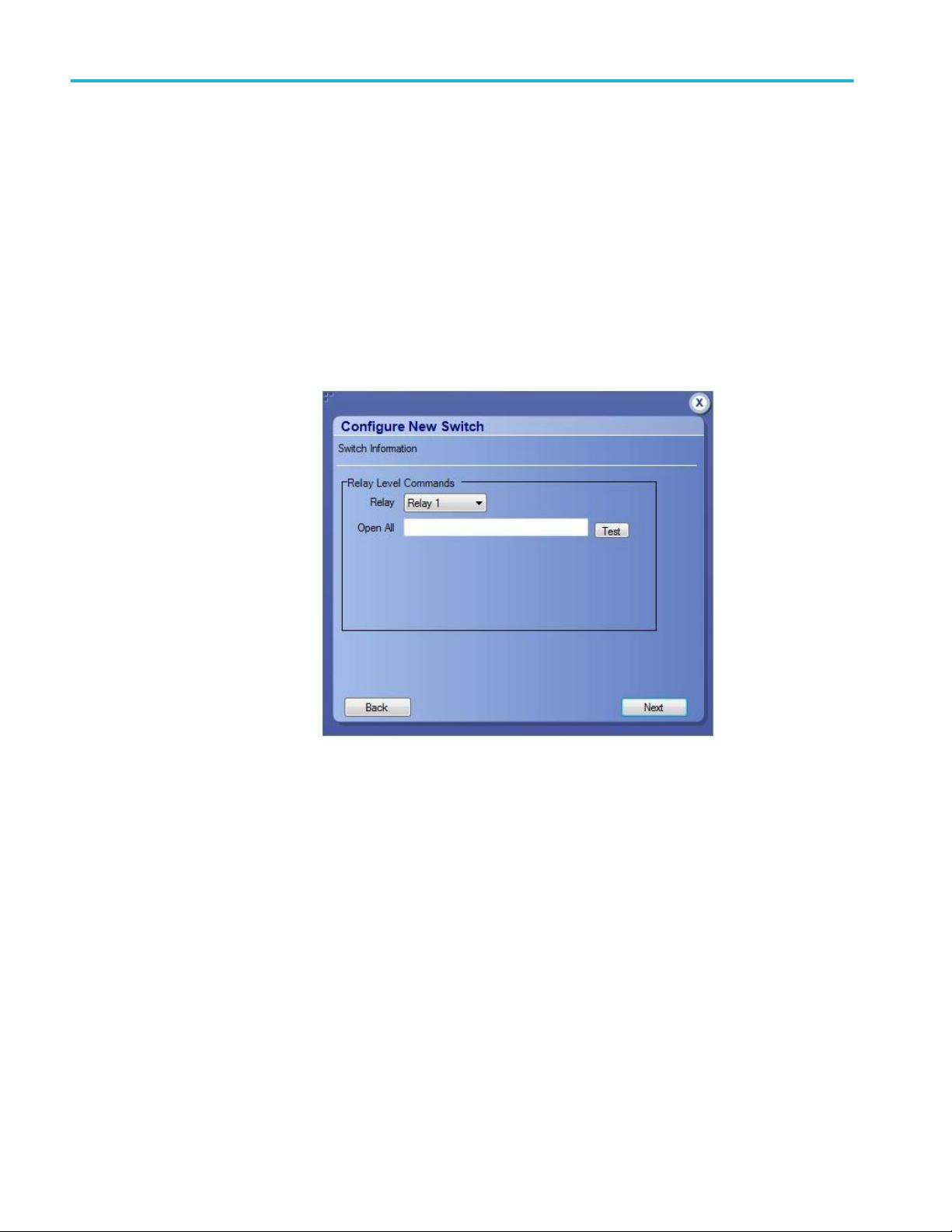
5. Relay Level Commands: Configure the commands for the selected relay;
click Test to execute the command. The command execution status is
indicated by the success/failure indicator displayed next to the Test button.
a. Relay: Select the relay.
b. Open All: Enter the command to open all the channels of the selected
relay.
c. Configure the relay level commands and click Next.
24 Switch Matrix application help
Page 33

Operating basics
6. Connection Level Commands: Configure the commands for relay
connections; click Test to execute the command.
a. Relay: Select the relay.
b. Input: Select the input of the relay.
c. Retain values from previous connection: Select to use the values from the
previous connection.
d. Open: Enter the command to open the channel.
e. Close: Enter the command to close the channel.
f. Status Check: Enter the command to check the status of the channel.
g. Validate the Status Check response:
a. Status Check Criteria: This allows you to validate the command
response of Status Check. Enter the Search Keyword and select the
validation method.
a. Contains: Checks for the keyword in the response.
b. Equals: Checks whether the response is equal to the keyword.
c. Starts with: Checks whether the response starts with the
keyword.
d. Ends with: Checks whether the response ends with the keyword.
b. Search Keyword: Enter the string that needs to be validated in the
String Check command response.
c. Add: Click to add the string in the search keyword to the list.
d. Delete: Select the search keyword in the list and click delete to delete
from the list.
Switch Matrix application help 25
Page 34

Operating basics
7. Configure all the mandatory commands and click Finish to load the switch
configurations.
NOTE.
■
To save the switch configurations, click Save from the Switch Matrix menu.
■
To edit the switch settings, select Options > Edit/Configure New Switch.
Link width
Debug mode
Link width determines the number of DUT signals. For example, x8 represents an
eight lane DUT.
This works in conjunction with the signal polarity selected for each relay. For
example, if the link width is x8, and:
■
If the signal polarity is Positive, then the signal drop-down list will have
selections from Lane0+ to Lane7+.
■
If the signal polarity is Negative, then the signal drop-down list will have
selections from Lane0- to Lane7-.
■
If the signal polarity is Differential, then the signal drop-down list will have
selections from Lane0 to Lane7.
Init Switch. Enter the Switch Address and click Init Switch to initialize the
switch. This will synchronize the configuration of relay(s) in the application with
the relay(s) in the switch. Synchronization will only be successful for those relays
that match the physical switch. Pass/Fail status is displayed next to the button.
The factory default GPIB address for Keithley (GPIB0::7::INSTR) and
Gigatronics (GPIB0::4::INSTR) is populated in the switch address based on the
configured vendor. You can enter the address in GPIB (GPIB0:X:INSTR) or
TCPIP (TCPIP::IPADDR::INSTR) format.
NOTE. Relay configurations (number of relays, number of relay inputs, and name
of relays) in the application should match the physical switch, for successful
synchronization.
Switch Self-Test. This will close and open all switch channels one-by-one. A
selftest report (CSV) is generated at the end of the process. You cannot abort this
process.
NOTE. Initialize the switch before performing the Switch Self-Test.
Reset Switch. Click Reset Switch to reset the switch. This will open all channels.
26 Switch Matrix application help
Page 35

Operating basics
Init Scope. Enter the oscilloscope address in the Scope Address field and click
Init Scope to initialize the oscilloscope. This will establish the connection with
the oscilloscope. The pass/fail status is displayed next to the button.
You can enter the address in GPIB (GPIB0:X:INSTR) or TCPIP
(TCPIP::IPADDR::INSTR) format.
When the oscilloscope is initialized and de-embed settings are configured,
closing a connection will apply the de-embed settings and then close the
connection.
NOTE. The virtual GPIB address of the oscilloscope is GPIB8::1::INSTR.
NOTE. If oscilloscope fails to respond to the *IDN? query during initialization,
then the connection attempt is considered a failure.
Cascade (Relay cascade)
This feature allows you to cascade the relay by connecting the common channel
as an input signal for another relay.
To cascade, select Cascade in the relay and select the Relay and Input of the
relay. Check that the selected relay signal displays the relay name, specifying that
the lane input signal is the output from that relay.
Switch Matrix application help 27
Page 36

Operating basics
Figure 2: Graphical view of relay cascade configuration
28 Switch Matrix application help
Page 37

Operating basics
TIP. Switch Matrix application supports only single-level cascading of the relays.
For example, if the Relay A output is cascaded to Relay B, then the Relay B
output cannot be cascaded.
Switch Matrix application help 29
Page 38

Operating basics
30 Switch Matrix application help
Page 39

Tutorial
Gigatronics switch configuration with cascade settings
1. Click Analyze > Switch Matrix from the TekScope menu.
2. Select Configuration > Gigatronics ASCOR 8000.
3. The following default configuration will be loaded:
■
Link Width - 16
■
De-embed as None
■
Four SP8T relays (S1 - Positive, S3 - Negative, S4 - Positive, S6 Negative) and two SP2T relays (S2 - Positive and S5 - Negative)
4. Configure the relay settings:
a. Select Signal connection for S1:
a. Lane0+; Lane1+; Lane2+; Lane3+; Lane4+; Lane5+; Lane6+;
Lane7+
b. Select Signal connection for S3:
a. Lane0-; Lane1-; Lane2-; Lane3-; Lane4-; Lane5-; Lane6-; Lane7-
c. Select Signal connection for S4:
a. Lane8+; Lane9+; Lane10+; Lane11+; Lane12+; Lane13+; Lane14+;
Lane15+
d. Select Signal connection for S6:
a. Lane8-; Lane9-; Lane10-; Lane11-; Lane12-; Lane13-; Lane14-;
Lane15-
5. Configure cascade settings:
Select the Cascade checkbox in all SP8T relays and select the following
Relay and Input settings:
■
Cascade S1 to Relay S2, Input NO
■
Cascade S3 to Relay S5, Input NO
■
Cascade S4 to Relay S2, Input NC
■
Cascade S6 to Relay S5, Input NC
6. Select S2 Common to Ch1 and S5 Common to Ch2.
7. Click Save; enter the file name in the Configuration Save dialog box, and
click Save.
Switch Matrix application help 31
Page 40

Tutorial
Figure 3: Gigatronics switch configuration with cascade settings
Create a new configuration (four lane, two SP4T relays)
1. Click Analyze > Switch Matrix from the TekScope menu.
2. Select Configuration > New Configuration (Select Auto Detect to
autodetect the switch).
3. Select Link Width > x8.
4. Select De-embed as None.
5. Select four SP6T and two SP2T relays and click Load. Check that the relays
are loaded.
6. Relay configuration:
a. Select the Signal Polarity as Positive for Relay A, Relay C, Relay 1 and
Negative for Relay B, Relay D, Relay2.
b. Select Signal connection for Relay A:
a. Lane0+; Lane1+; Lane2+; Lane3+; Lane4+; Lane5+; Lane6+;
Lane7+
c. Select Signal connection for Relay B:
a. Lane0-; Lane1-; Lane2-; Lane3-; Lane4-; Lane5-; Lane6-; Lane7-
d. Select Signal connection for Relay C:
a. Lane8+; Lane9+; Lane10+; Lane11+; Lane12+; Lane13+; Lane14+;
Lane15+
e. Select Signal connection for Relay D:
a. Lane8-; Lane9-; Lane10-; Lane11-; Lane12-; Lane13-; Lane14-;
Lane15-
32 Switch Matrix application help
Page 41

Tutorial
7. Configure cascade settings:
Select the Cascade checkbox in all SP6T relays and select the following
Relay and Input settings:
■
Cascade Relay A to Relay 1, Input NO
■
Cascade Relay B to Relay 2, Input NO
■
Cascade Relay C to Relay 1, Input NC
■
Cascade Relay D to Relay 2, Input NC
8. Select Relay 1 Common to Ch1 and Relay 2 Common to Ch2.
9. Click Save; enter the file name in the Configuration Save dialog box, and
click Save.
Configure the filter file for each relay separately
1. Click Analyze > Switch Matrix from the TekScope menu.
2. Select Configuration > Keithley S46T.
3. Select the De-embed option as Each relay separately and do the following:
a. Click Select Filter File.
b. Select Relay as Relay A in the De-embed Settings dialog box; browse for
the Switch Filter File.
c. Repeat Step 3.b for all the relays.
For improved performance during execution, the single filter file (.flt) for the
entire signal path is recommended. If a separate filter file has to be applied
for a fixture, then select Choose filter file for fixture, and browse for the
Fixture Filter File.
4. Close the filter file window. Observe that the relays with selected filter files
show ✓ against all connections in the Filter File column.
5. Click Save; enter the file name in the Configuration Save dialog box and
click Save.
Switch Matrix application help 33
Page 42

Tutorial
Debug the Keithley S46T switch
1. Click Analyze > Switch Matrix from the TekScope menu.
2. Select Configuration > Keithley S46T.
3. Select De-embed as None.
4. Select Debug Mode and do the following:
a. Enter the Switch Address and click Init Switch. The switch initialization
status should be Pass.
b. Click Switch Self-Test.
c. Enter the oscilloscope address in the Scope Address field and click Init
Scope. The switch initialization status should be Pass.
d. Click the input toggle button of the channel to close or open the channel
manually (this is enabled only in debug mode and only if a valid signal is
configured for the channel).
5. Click Save; enter the file name in the Configuration Save dialog box, and
click Save.
34 Switch Matrix application help
Page 43

SCPI commands
About SCPI commands
You can use Standard Commands for Programmable Instruments (SCPI) to
communicate with the TekExpress application.
Socket configuration for SCPI commands
This section describes the steps for TCPIP socket configuration and TekVISA
configuration to execute the SCPI commands.
TCPIP socket
configuration
1. Click Start > Control Panel > System and Security > Windows Firewall >
Advanced settings.
Switch Matrix application help 35
Page 44

SCPI commands
2. In Windows Firewall with Advanced Security menu, select Windows
Firewall with Advanced Security on Local Computer > Inbound Rules
and click New Rule…
3. In New Inbound Rule Wizard menu:
a. Select Port and click Next.
36 Switch Matrix application help
Page 45

b. Select TCP and enter 5000 for Specific local ports and click Next.
SCPI commands
c. Select Allow the connection and click Next.
Switch Matrix application help 37
Page 46

SCPI commands
d. Select Domain,Private,Public, and click Next.
e. Enter Name, Description (optional), and click Finish.
38 Switch Matrix application help
Page 47

4. Verify the Rule name is displayed in Windows Firewall with Advanced
Security menu > Inbound Rules.
SCPI commands
TekVISA configuration
1. Click Start > All Programs > TekVISA > OpenChoice Instrument
Manager.
Switch Matrix application help 39
Page 48

SCPI commands
2. Click Search Criteria. In the Search Criteria menu, click LAN to Turn-on.
Select Socket from the drop-down list, enter the IP address of the
TekExpress device in Hostname field and set the Port to 5000. Click
to configure the IP address with Port.
Enter the Hostname as 127.0.0.1 if the TekVISA and TekExpress application
are in the same system, otherwise enter the IP address of the TekExpress
application system.
40 Switch Matrix application help
Page 49

SCPI commands
3. Click Search to set up the TCPIP connection with the host. Check whether
the TCPIP host name is displayed under OpenChoice Instrument Manager
> Instruments.
4. Double-click OpenChoice Talker Listener, enter *IDN? in command entry
field and click Query. Check that the Operation is successful and Talker
Listener Readout displays the Command and Data.
Switch Matrix application help 41
Page 50

SCPI commands
SWITCH:*IDN
This command queries the switch matrix version information.
SWITCH:*OPC
Syntax
Inputs
Outputs
Example
Syntax
SWITCH:*IDN?\n
NA
Returns the switch martrix version information.
SWITCH:*IDN?\n returns "Tektronix,Switch Matrix,v1.0.0.0", where v1.0.0.0 is
the Switch Matrix version.
This command queries the previously executed commands execution status.
SWITCH:*OPC?\n
Inputs
Outputs
Example
NA
Returns 0 if the previously executed command execution is in progress.
Returns 1 if the previously executed command execution is done.
SWITCH:*OPC?\n returns 1, when the previously executed command execution
is done.
42 Switch Matrix application help
Page 51

SCPI commands
SWITCH:CONFIG
This command sets or queries the config file.
Syntax
Inputs
Outputs
Examples
SWITCH:CONFIG {"<ConfigName>" | "<UserConfigFilePath>"}\n
SWITCH:CONFIG?\n
<ConfigName> specifies the config file.
<UserConfigFilePath> specifies the config file from the given path.
Returns the loaded config file name with path.
SWITCH:CONFIG "Keithley S46T"\n sets the config file of Keithley.
SWITCH:CONFIG "E:\myconfig.xml"\n sets the config file from the given path.
SWITCH:CONFIG?\n returns "E:\myconfig.xml".
SWITCH:DE-EMBED:ALL:FILTER_FILE
This command sets the filter file for all connections.
Syntax
Inputs
SWITCH:DE-EMBED:ALL:FILTER_FILE
"<SwitchFilterFilePath>","<FixtureFilterFilePath>"\n
<SwitchFilterFilePath> specifies the switch filter file path.
<FixtureFilterFilePath> specifies the fixture filter file path.
Switch Matrix application help 43
Page 52

SCPI commands
Outputs
Example
NA
SWITCH:DE-EMBED:ALL:FILTER_FILE "C:\FilterFiles\SWTCH1.flt","C:
\FilterFiles\CABLE_1.flt"\n sets the switch filter file for all connections and the
fixture filter file for all cables connected.
SWITCH:DE-EMBED:CONN:FILTER_FILE
This command sets the filter file for the switch, fixture, and cable for the
specified connection.
Syntax
Inputs
SWITCH:DE-EMBED:CONN:FILTER_FILE
"<RelayName>","<InputName>","<SwitchFilterFilePath>","<FixtureFilterFilePa
th>","<CableFilterFilePath>"\n
<RelayName> specifies the relay name.
<InputName> specifies the input name.
Example
<SwitchFilterFilePath> specifies the switch filter file path.
<FixtureFilterFilePath> specifies the fixture filter file path.
<CableFilterFilePath> specifies the cable filter file path.
SWITCH:DE-EMBED:CONN:FILTER_FILE "Relay A","1","C:\FilterFiles
\RA_1.flt","C:\FilterFiles\Fxtre_1.flt","C:\FilterFiles\cbl_1.flt"\n sets filter files
to Relay A's input 1 and to the connected cable.
44 Switch Matrix application help
Page 53

SCPI commands
SWITCH:DE-EMBED:FILTER_FILE
This command queries the filter file based on the mode selected in the
application.
Syntax
Inputs
Outputs
Example
SWITCH:DE-EMBED:FILTER_FILE?\n
NA
Returns the filter file in any of the the below specified format, based on the mode
selected.
None
ALL;"<SwitchFilterFilePath>","<FixtureFilterFilePath>";
RELAY_TYPE;"<RelayType1>","<SwitchFilterFilePath1>","<FixtureFilterFilePath1>";"<RelayType
2>","<SwitchFilterFilePath2>","<FixtureFilterFilePath2>";
RELAY;"<RelayName1>","<SwitchFilterFilePath1>","<FixtureFilterFilePath1>";"<RelayName2>","<
SwitchFilterFilePath2>","<FixtureFilterFilePath2>";
CONN;"<RelayName1>","<InputName1>,"<SwitchFilterFilePath1>","<FixtureFilterFilePath1>","<C
ableFilterFIlePath1>;"<RelayName1>","<InputName2>,"<SwitchFilterFilePath2>","<FixtureFilterFil
ePath2>","<CableFilterFIlePath2>;
SWITCH:DE-EMBED:FILTER_FILE?\n returns ALL;"C:\FilterFiles
\SWTCH1.flt" ,"C:\FilterFiles\Fxtre_1.flt".
Switch Matrix application help 45
Page 54

SCPI commands
SWITCH:DE-EMBED:MODE
This command sets or queries the De-Embed mode.
Syntax
Inputs
Outputs
Examples
SWITCH:DE-EMBED:MODE {NONE | ALL | RELAY_TYPE | RELAY |
CONN}\n
SWITCH:DE-EMBED:MODE?\n
{NONE | ALL | RELAY_TYPE | RELAY | CONN}
Returns the De-Embed mode.
SWITCH:DE-EMBED:MODE ALL\n sets the De-Embed mode as ALL.
SWITCH:DE-EMBED:MODE?\n returns ALL.
SWITCH:DE-EMBED:RELAY:FILTER_FILE
This command sets the filter file and fixture file for the specified relay.
Syntax
SWITCH:DE-EMBED:RELAY:FILTER_FILE
"<RelaName>","<SwitchFilterFilePath>","<FixtureFilterFilePath>"\n
Inputs
46 Switch Matrix application help
<RelaName> specifies the relay name.
<SwitchFilterFilePath> specifies the switch filter file path.
<FixtureFilterFilePath> specifies the fixture filter file path.
Page 55

SCPI commands
Outputs
SWITCH:DE-EMBED:RELAY:FILTER_FILE "Relay A","C:\FilterFiles
\RA.flt","C:\FilterFiles\Fxtre_1.flt"\n sets filter files for all connections in Relay
A.
SWITCH:DE-EMBED:RELAY_TYPE:FILTER_FILE
This command sets the filter file for specified relay type.
Syntax
Inputs
Example
SWITCH:DE-EMBED:RELAY_TYPE:FILTER_FILE
"<RelayType>","<SwitchFilterFilePath>","<FixtureFilterFilePath>"\n
<RelayType> specifies the relay type.
<SwitchFilterFilePath> specifies the switch filter file path.
<FixtureFilterFilePath> specifies the fixture filter file path.
SWITCH:DE-EMBED:RELAY_TYPE:FILTER_FILE "SP2T","C:\FilterFiles
\SP2T.flt","C:\FilterFiles\Fxtre_1.flt"\n sets filter file for SP2T relay type.
SWITCH:LASTERROR
Syntax
Inputs
This command queries the error occurred while executing last command.
SWITCH:LASTERROR?\n
NA
Switch Matrix application help 47
Page 56

SCPI commands
Outputs
Returns the error occurred while executing last command.
Error message Description
NO_ERROR No error occurred executing last command.
INVALID_COMMAND The last command sent is either invalid or
syntax is not correct.
"No config file loaded." The last command to load the config file is
failed.
"Invalid configuration." The last command has invalid configuration.
"Invalid linkwidth." The last command has invalid linkwidth.
"Invalid de-embed mode." The last command has invalid de-embed mode.
"Invalid signal polarity." The last command has invalid signal polarity.
"Invalid relay name." The last command has invalid relay name.
"Invalid relay type." The last command has invalid relay type.
"Invalid signal name." The last command has invalid signal name.
"Invalid common value." The last command has invalid value for
common.
"Invalid input ID." The last command has invalid input ID.
Example
SWITCH:LINKWIDTH
Syntax
SWITCH:LASTERROR?\n returns the last error occurred.
This command sets or queries the link width.
SWITCH:LINKWIDTH {X2 | X4 | X8 | X16}\n
SWITCH:LINKWIDTH?\n
48 Switch Matrix application help
Page 57

SCPI commands
Inputs
Outputs
Examples
{X2 | X4 | X8 | X16}
Returns the link width value.
SWITCH:LINKWIDTH X8\n sets the linkWidth to 8.
SWITCH:LINKWIDTH?\n returns 8.
SWITCH:RELAY:CASCADE
This command sets or queries the cascade of the relay.
Syntax
Inputs
SWITCH:RELAY:CASCADE
"<FromRelayName>","<ToRelayName>","<InputName>"\n
SWITCH:RELAY:CASCADE? "<RelayName>"\n
<FromRelayName> specifies the relay name from which to cascade.
Outputs
Example
<ToRelayName> specifies the relay name to cascade.
<InputName> specifies the input name of the relay to cascade.
<RelayName> specifies the relay name.
Returns the cascading info of the relay if cascaded else returns
NOT_CASCADED.
SWITCH:RELAY:CASCADE "Relay A","Relay B","2"\n sets Relay A's output
cascade to Relay B's input 2.
SWITCH:RELAY:CASCADE? "Relay A"\n returns "Relay B","2".
SWITCH:RELAY:CASCADE? "Relay B"\n returns NOT_CASCADED.
Switch Matrix application help 49
Page 58

SCPI commands
SWITCH:RELAY:CASCADED
This command sets or queries cascaded state of the relay.
Syntax
Inputs
Outputs
Examples
SWITCH:RELAY:CASCADED "<RelayName>",{TRUE | FALSE}\n
SWITCH:RELAY:CASCADED? "<RelayName>"\n
<RelayName> specifies the relay name.
TRUE or FALSE to cascade the relay or not.
Returns whether the relay is cascaded or not.
SWITCH:RELAY:CASCADED "Relay A",TRUE\n sets the cascaded state of
Relay A to TRUE.
SWITCH:RELAY:CASCADED? "Relay A"\n returns TRUE.
SWITCH:RELAY:COMMON
This command sets or queries the relays common connection connected to scope
channels.
Syntax
Inputs
SWITCH:RELAY:COMMON "<RelayName>",{CH1 | CH2 | CH3 | CH4}\n
SWITCH:RELAY:COMMON? "<RelayName>"\n
<RelayName> specifies the relay name.
{CH1 | CH2 | CH3 | CH4} specifies the channel number.
50 Switch Matrix application help
Page 59

SCPI commands
Outputs
Example
Returns the channel connected to the common connection of relay.
SWITCH:RELAY:COMMON "Relay A",CH1\n sets the common connection of
Relay A to CH1.
SWITCH:RELAY:COMMON? "Relay A"\n returns CH1.
SWITCH:RELAY:POLARITY
This command sets or queries the signal polarity of the specified relay.
Syntax
Inputs
SWITCH:RELAY:POLARITY "<RelayName>",{POS | NEG | DIFF}\n
SWITCH:RELAY:POLARITY? "<RelayName>"\n
<RelayName> specifies the relay name.
{POS | NEG | DIFF} specifies the signal polarity as Positive, Negative or
Differential respectively.
Outputs
Examples
Returns the signal polarity of the relay.
SWITCH:RELAY:POLARITY "Relay A",POS\n sets the Relay A's signal
polarity to POS.
SWITCH:RELAY:POLARITY? "Relay A"\n returns POS.
Switch Matrix application help 51
Page 60

SCPI commands
SWITCH:RELAY:SIGNAL
This command sets or queries the signal name connected to input port.
Syntax
Inputs
Outputs
Example
SWITCH:RELAY:SIGNAL
"<RelayName>","<InputName>","<SignalName>"\n
SWITCH:RELAY:SIGNAL? "<RelayName>","<InputName>"\n
<RelayName> specifies the relay name.
<InputName> specifies the input name of the relay.
<SignalName> specifies the signal name to connect to the relays input.
Returns the signal name connected to the input port.
SWITCH:RELAY:SIGNAL "Relay A","1","Lane0+"\n sets the signal name
Lane0+ to Relay A's input 1.
SWITCH:RELAY:SIGNAL? "Relay A","1"\n returns "Lane0+".
52 Switch Matrix application help
Page 61

Reference
Error messages
Error message Possible solution
"A filename cannot be empty and it cannot
contain any of the following characters:\n\t. .. \
\ / : ? \" < > | * ! @ # $ % ^ & * ( ) - + ., / \\ \' < >
Also, the file name cannot be \"Keithley S46T\",
\"Gigatronics ASCOR 8000\",\"Select\", \"New
Configuration\", \"Custom\" , \"Auto Detect\" or
\"Show All Files\""
Configure appropriate signals before the deembed settings.
Either the instrument address is invalid or
instrument is not connected.
Error occurred while trying to recall the
configuration settings.
Try re-creating configuration or recalling a
different configuration file.
Error occurred while trying to access the
connection for open/close operation.
Filter file <FilterFileName> not found. Reselect the de-embed filter file and try again.
Graphical view is not generated or does not
exist.
Initialize the switch Initialize the switch and then perform the switch
Instrument address doesn't belong to any
supported switch.
Instrument address is empty. Instrument address cannot be empty. Enter a
No switch detected. Connect a Keithley or
Gigatronics switch and try auto detection by
selecting Configuration > Auto Detect.
Number of relays cannot be more than 26
Please ensure that the name(s) of the
configured relay(s) match the ones present on
the physical switch.
Relay name cannot be empty
Select at least one signal for a relay before
configuring the de-embed settings.
Check the GPIB connection from oscilloscope to
switch and verify the instrument address.
Re-create the configuration file or recall a
different configuration file.
operations.
Verify the switch address.
valid instrument address in the GPIB
(GPIB0:X:INSTR) or TCPIP
(TCPIP::IPADDR::INSTR) format.
Check the GPIB connection from the
oscilloscope to switch and whether the
instrument is detected in TekVisa.
Switch Matrix application help 53
Page 62

Reference
Error message Possible solution
Scope initialization failed. Check if the address
is valid and ensure that the instrument is
switched on and try again.
Switch communication failed... Ensure that the switch is on. Reset the switch
Switch initialization failed. Check if the address
is valid and ensure that the instrument is
switched on and try again.
The start count cannot be more than 74
Timeout Error. Either the command is invalid or
instrument is not active.
Two or more lanes have same name. The lane
names should be unique.
Two or more relays have same name.
Validate the oscilloscope address try again.
and try again.
Validate the switch address and ensure that the
instrument is switched on. Try again.
Check the command syntax and the connection
of the instrument by SWITCH:*IDN command.
54 Switch Matrix application help
Page 63

Index
A
Application overview, 9
Application version (show), 5
P
Purchase the license, 4
C
Cascade, 27
Cascade (relay cascade), 27
Channel Status, 13
Contacting Tektronix, 2
D
De-embed settings
apply a filter file for all relays, 17
apply a filter file for each connection separately,
19
apply a filter file for each relay separately, 18
apply a filter file for each relay type separately, 18
E
Error messages, 53
G
Graphical view of switch matrix configuration, 20
H
Help conventions, 1
I
Initialize the oscilloscope, 27
Installing the software
switch matrix application, 4
L
Launch the application, 7
License agreement (show), 5
Link width, 26
M
Minimum system requirements, 3
R
Related documentation, 1
Relay cascade, 27
Relay configuration
cascade, 14
common, 15
relay name, 14
signal, 15
signal polarity, 14
S
Saving the switch matrix configuration, 20
SCPI commands
socket configuration, 35
SWITCH׃*IDN, 42
SWITCH׃*OPC, 42
SWITCH׃CONFIG, 43
SWITCH׃DE-EMBED׃ALL׃FILTER_FILE, 43
SWITCH׃DE-EMBED׃CONN׃FILTER_FILE, 44
SWITCH׃DE-EMBED׃FILTER_FILE, 45
SWITCH׃DE-EMBED׃MODE, 46
SWITCH׃DE-EMBED׃RELAY_TYPE׃
FILTER_FILE, 47
SWITCH׃DE-EMBED׃RELAY׃FILTER_FILE,
46
SWITCH׃LASTERROR, 47
SWITCH׃LINKWIDTH, 48
SWITCH׃RELAY׃CASCADE, 49
SWITCH׃RELAY׃CASCADED, 50
SWITCH׃RELAY׃COMMON, 50
SWITCH׃RELAY׃POLARITY, 51
SWITCH׃RELAY׃SIGNAL, 52
TCPIP socket configuration, 35
TekVISA configuration, 35
Software installation
switch matrix application, 4
Status indicators, 6
Switch Matrix application help 55
Page 64

Index
Support, 2
Switch matrix configuration
additional lanes, 10
configuration, 10
de-embed, 11
debug mode, 12
graphical view, 14
link width, 10
relays, 13
rename lanes, 11
vendor, 10
Switch self test, 26
T
Technical support, 2
Tutorials
configure filter file for each relay separately, 33
create a new configuration (four lane, two SP4T
relays), 32
debug Keithley S46T switch, 34
Gigatronics switch configuration with cascade
settings, 31
V
View application license agreement, 5
View application software version, 5
56 Switch Matrix application help
 Loading...