

Page 1
Keithley Instruments, Inc.
28775 Aurora Road
Cleveland, Ohio 44139
(440) 248-0400
Fax: (440) 248-6168
www.keithley.com
WARNING This accessory is not intended for use in circuits carrying voltages in excess of 30V RMS,
42.4V peak, or 60VDC.
ST A-U Universal Screw Terminal Accessory
Packing List
Description
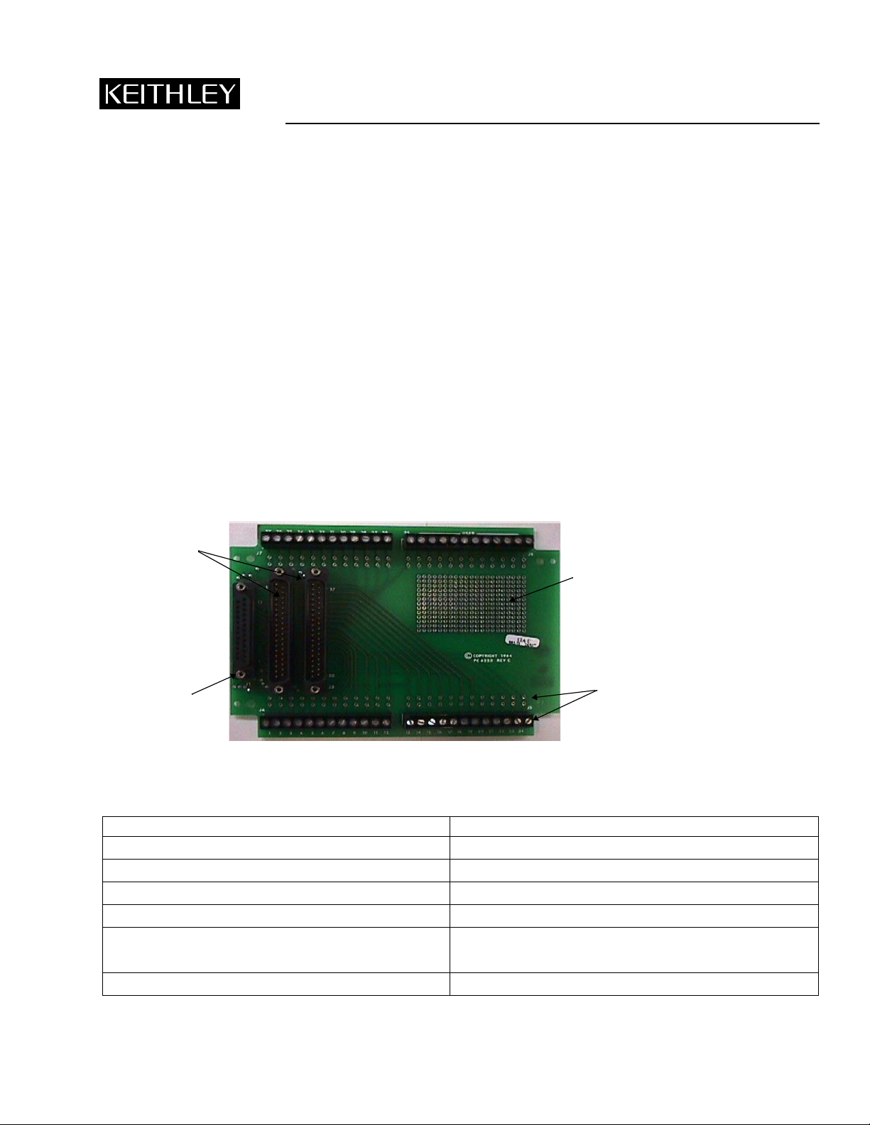
The STA-U screw terminal accessory interfaces Keithley data acquisition boards with multiple types of input/output (I/O) connections. All interconnections are provided on a printed circuit board, mounted in a covered plastic box. The pins of three D
connectors are connected to each other and to screw terminals and solder pads. An isolated matrix of 21 x 13 solder pads provides for breadboarding of small circuit circuits. Eleven unallocated screw terminals, each connected to an adjacent pair of solder pads, allow user connections, such as breadboard power input, etc. See Figure 1 and refer to Table 1.
Figure 1
Layout of the STA-U Universal Screw Terminal Accessory
First 37-pin male
D connectors
Solder pad
matrix
Screw terminal and
25-pin female
D connector
Table 1
Correspondence of numbered pins, screw terminals and solder pads
Termination Corresponding pin/screw terminal/solder pad numbers
Numbered screw terminals and adjacent two solder pads 1 2 3 …... 25 …... 36
First 37-pin male D connector 1 2 3 …... 25 .….. 36
Second 37-pin male D connector 1 2 3 .….. 25 …... 36
25-pin female D connector 1 2 3 …... 25
Unnumbered user screw terminals and adjacent solder pads Each terminal and adjacent two solder pads are connected.
There are no other connections.
Solder pad matrix of (21 x 13 pads), for breadboarding No connections
adjacent two solder
pads (typical)
PA-591 Rev. B / 7-01
Page 2

Specifications
Voltage: 30V RMS, 42.4V peak, or 60VDC
Current: 1A maximum
Screw terminal wire size capacity: 12-22 AWG
Safety precautions
The following safety precautions should be observed before using this product and any associated instrumentation. Although
some instruments and accessories would normally be used with non-hazardous voltages, there are situations where hazardous
conditions may be present.
This product is intended for use by qualified personnel who recognize shock hazards and are familiar with the safety precautions
required to avoid possible injury. Read the operating information carefully before using the product.
General safety definitions
The types of product users are:
Responsible body is the individual or group responsible for the use and maintenance of equipment, for ensuring that the equip-
ment is operated within its specifications and operating limits, and for ensuring that operators are adequately trained.
Operators use the product for its intended function. They must be trained in electrical safety procedures and proper use of the
instrument. They must be protected from electric shock and contact with hazardous live circuits.
Maintenance personnel perform routine procedures on the product to keep it operating, for example, setting the line voltage
or replacing consumable materials. Maintenance procedures are described in the manual. The procedures explicitly state if the
operator may perform them. Otherwise, they should be performed only by service personnel.
Service personnel are trained to work on live circuits, and perform safe installations and repairs of products. Only properly
trained service personnel may perform installation and service procedures.
If a screw is present, connect it to safety earth ground using the wire recommended in the user documentation.
!
The symbol on an instrument indicates that the user should refer to the operating instructions located in the manual.
The symbol on an instrument shows that it can source or measure 1000 volts or more, including the combined effect of
normal and common mode voltages. Use standard safety precautions to avoid personal contact with these voltages.
The WARNING heading in a manual explains dangers that might result in personal injury or death. Always read the associated
information very carefully before performing the indicated procedure.
The CAUTION heading in a manual explains hazards that could damage the instrument. Such damage may invalidate the
warranty.
2
Page 3

Installation safety
Keithley products are designed for use with electrical signals that are rated Installation Category I and Installation Cate gory II,
as described in the International Electrotechnical Commission (IEC) Standard IEC 60664. Most measurement, control, and data
I/O signals are Installation Category I and must not be directly connected to mains voltage or to voltage sources with high transient over-v oltages. Installation Category II connections require protection for high transient over -voltages often associated with
local AC mains connections. The user should assume all measurement, control, and data I/O connections are for connection to
Category I sources unless otherwise marked or described in the Manual.
Users of this product must be protected from electric shock at all times. The responsible body must ensure that users are prevented access and/or insulated from every connection point. In some cases, connections must be exposed to potential human
contact. Product users in these circumstances must be trained to protect themselves from the risk of electric shock. If the circuit
is capable of operating at or above 1000 volts, no conductive part of the circuit may be exposed.
Do not connect switching cards directly to unlimited power circuits. They are intended to be used with impedance limited
sources. NEVER connect switching cards directly to AC mains. When connecting sources to switching cards, install protective
devices to limit fault current and voltage to the card.
Before operating an instrument, make sure the line cord is connected to a properly grounded power receptacle. Inspect the connecting cables, test leads, and jumpers for possible wear, cracks, or breaks before each use.
When installing equipment where access to the main power cord is restricted, such as rack mounting, a separate main input
power disconnect device must be provided, in close proximity to the equipment and within easy reach of the operator.
Operation safety
Exercise extreme caution when a shock hazard is present. Lethal voltage may be present on cable connector jacks or test fixtures.
The American National Standards Institute (ANSI) states that a shock hazard e xists when voltage le vels greater than 30V RMS,
42.4V peak, or 60VDC are present. A good safety practice is to expect that hazardous voltage is present in any unknown
circuit before measuring.
For maximum safety, do not touch the product, test cables, or any other instruments while power is applied to the circuit under
test. ALWAYS remove power from the entire test system and discharge any capacitors before: connecting or disconnecting
cables or jumpers, installing or removing switching cards, or making internal changes, such as installing or removing jumpers.
Do not touch any object that could provide a current path to the common side of the circuit under test or power line (earth)
ground. Alw ays make measurements with dry hands while standing on a dry, insulated surface capable of withstanding the voltage being measured.
Do not exceed the maximum signal levels of the instruments and accessories, as defined in the specifications and operating
information, and as shown on the instrument or test fixture panels, or switching card.
The instrument and accessories must be used in accordance with its specifications and operating instructions or the safety of the
equipment may be impaired.
Do not exceed the maximum signal levels of the instruments and accessories, as defined in the specifications and operating
information, and as shown on the instrument or test fixture panels, or switching card.
When fuses are used in a product, replace with same type and rating for continued protection against fire hazard.
Chassis connections must only be used as shield connections for measuring circuits, NOT as safety earth ground connections.
If you are using a test fixture, keep the lid closed while power is applied to the device under test. Safe operation requires the use
of a lid interlock.
Instrumentation and accessories shall not be connected to humans.
3
Page 4

Maintenance and service for safety
Before performing any maintenance, disconnect the line cord and all test cables.
T o maintain protection from electric shock and fire, replacement components in mains circuits, including the power transformer ,
test leads, and input jacks, must be purchased from Keithley Instruments. Standard fuses, with applicable national safety approvals, may be used if the rating and type are the same. Other components that are not safety related may be purchased from other
suppliers as long as they are equivalent to the original component. (Note that selected parts should be purchased only through
Keithley Instruments to maintain accuracy and functionality of the product.) If you are unsure about the applicability of a
replacement component, call a Keithley Instruments office for information.
Cleaning
To clean an instrument, use a damp cloth or mild, water based cleaner. Clean the exterior of the instrument only. Do not apply
cleaner directly to the instrument or allow liquids to enter or spill on the instrument. Products that consist of a circuit board with
no case or chassis (e.g., data acquisition board for installation into a computer) should never require cleaning if handled according to instructions. If the board becomes contaminated and operation is affected, the board should be returned to the factory for
proper cleaning/servicing.
Installation
A variety of boards may be connected to the STA-U accessory. Installation depends on the product used. Before making connections, refer to the users’ guide that accompanies your data acquisition board.
An optional C1800 cable may be used to connect the STA-U to any data acquisition board having a 37-pin male connector, as
shown in Figure 2. At the STA-U, the cable may be connected to either of the two 37-pin D connectors.
Figure 2
Connecting the STA-U to the data acquisition board
Data acquisition board with
37-pin male D connector
C1800 cable
WARNING The maximum voltage allowed for a C1800 cable is 30V RMS, 42.4V peak, or 60VDC.
Exceeding this limit could cause an insulation failure and shock hazard.
STA-U
4
Page 5

Dimensions
Figure 3
Mounting dimensions (not to scale)
4.70 in.
106.7 mm
0.375 in.
9.5 mm
3.20 in.
81.3 mm
0.750 in.
19.1 mm
0.156 in.
4.0 mm
0.156 in.
4.0 mm
0.156 in.
4.0 mm
0.156 in.
4.0 mm
5.45 in.
138.4 mm
6.20 in.
157.5 mm
5
Page 6

6
 Loading...