

Page 1

SSIO-24 Digital I/O Board
User Guide
A GREATER MEASURE OF CONFIDENCE
Page 2

WARRANTY
Hardware
Keithley Instruments, Inc. warrants that, for a period of one (1) year from the date of shipment (3 years for Models 2000, 2001, 2002, 2010 and 2700), the Keithley Hardware product will be free from defects in materials or workmanship. This warranty will be honored
provided the defect has not been caused by use of the Keithley Hardware not in accordance with the instructions for the product. This warranty shall be null and void upon: (1)
any modification of Keithley Hardware that is made by other than Keithley and not
approved in writing by Keithley or (2) operation of the Keithley Hardware outside of the
environmental specifications therefore.
Upon receiving notification of a defect in the Keithley Hardware during the warranty
period, Keithley will, at its option, either repair or replace such Keithley Hardware. During
the first ninety days of the warranty period, Keithley will, at its option, supply the necessary on site labor to return the product to the condition prior to the notification of a defect.
Failure to notify Keithley of a defect during the warranty shall relieve Keithley of its obligations and liabilities under this warranty.
Other Hardware
The portion of the product that is not manufactured by Keithley (Other Hardware) shall not
be covered by this warranty, and Keithley shall have no duty of obligation to enforce any
manufacturers' warranties on behalf of the customer. On those other manufacturers’ products that Keithley purchases for resale, Keithley shall have no duty of obligation to enforce
any manufacturers’ warranties on behalf of the customer.
Software
Keithley warrants that for a period of one (1) year from date of shipment, the Keithley produced portion of the software or firmware (Keithley Software) will conform in all material
respects with the published specifications provided such Keithley Software is used on the product for which it is intended and otherwise in accordance with the instructions therefore. Keithley does not warrant that operation of the Keithley Software will be uninterrupted or errorfree and/or that the Keithley Software will be adequate for the customer's intended application
and/or use. This warranty shall be null and void upon any modification of the Keithley Software that is made by other than Keithley and not approved in writing by Keithley.
If Keithley receives notification of a Keithley Software nonconformity that is covered by
this warranty during the warranty period, Keithley will review the conditions described in
such notice. Such notice must state the published specification(s) to which the Keithley
Software fails to conform and the manner in which the Keithley Software fails to conform
to such published specification(s) with sufficient specificity to permit Keithley to correct
such nonconformity. If Keithley determines that the Keithley Software does not conform
with the published specifications, Keithley will, at its option, provide either the programming services necessary to correct such nonconformity or develop a program change to
bypass such nonconformity in the Keithley Software. Failure to notify Keithley of a nonconformity during the warranty shall relieve Keithley of its obligations and liabilities
under this warranty.
Other Software
OEM software that is not produced by Keithley (Other Software) shall not be covered by
this warranty, and Keithley shall have no duty or obligation to enforce any OEM's warranties on behalf of the customer.
Page 3

Other Items
Keithley warrants the following items for 90 days from the date of shipment: probes, cables,
rechargeable batteries, diskettes, and documentation.
Items not Covered under Warranty
This warranty does not apply to fuses, non-rechargeable batteries, damage from battery leakage, or problems arising from normal wear or failure to follow instructions.
Limitation of Warranty
This warranty does not apply to defects resulting from product modification made by Purchaser without Keithley's express written consent, or by misuse of any product or part.
Disclaimer of Warranties
EXCEPT FOR THE EXPRESS WARRANTIES ABOVE KEITHLEY DISCLAIMS ALL
OTHER WARRANTIES, EXPRESS OR IMPLIED, INCLUDING WITHOUT LIMITATION, ALL IMPLIED WARRANTIES OF MERCHANTABILITY AND FITNESS FOR A
PARTICULAR PURPOSE. KEITHLEY DISCLAIMS ALL WARRANTIES WITH
RESPECT TO THE OTHER HARDWARE AND OTHER SOFTWARE.
Limitation of Liability
KEITHLEY INSTRUMENTS SHALL IN NO EVENT, REGARDLESS OF CAUSE, ASSUME
RESPONSIBILITY FOR OR BE LIABLE FOR: (1) ECONOMICAL, INCIDENTAL, CONSEQUENTIAL, INDIRECT, SPECIAL, PUNITIVE OR EXEMPLARY DAMAGES, WHETHER
CLAIMED UNDER CONTRACT, TORT OR ANY OTHER LEGAL THEORY, (2) LOSS OF
OR DAMAGE TO THE CUSTOMER'S DATA OR PROGRAMMING, OR (3) PENALTIES
OR PENALTY CLAUSES OF ANY DESCRIPTION OR INDEMNIFICATION OF THE CUSTOMER OR OTHERS FOR COSTS, DAMAGES, OR EXPENSES RELATED TO THE
GOODS OR SERVICES PROVIDED UNDER THIS WARRANTY.
Keithley Instruments, Inc.
Sales Offices:BELGIUM: Bergensesteenweg 709 • B-1600 Sint-Pieters-Leeuw • 02-363 00 40 • Fax: 02/363 00 64
CHINA: Yuan Chen Xin Building, Room 705 • 12 Yumin Road, Dewai, Madian • Beijing 100029 • 8610-6202-2886 • Fax: 8610-6202-2892
FINLAND: Tietäjäntie 2 • 02130 Espoo • Phone: 09-54 75 08 10 • Fax: 09-25 10 51 00
FRANCE: 3, allée des Garays • 91127 Palaiseau Cédex • 01-64 53 20 20 • Fax: 01-60 11 77 26
GERMANY: Landsberger Strasse 65 • 82110 Germering • 089/84 93 07-40 • Fax: 089/84 93 07-34
GREAT BRITAIN: Unit 2 Commerce Park, Brunel Road • Theale • Berkshire RG7 4AB • 0118 929 7500 • Fax: 0118 929 7519
INDIA: Flat 2B, Willocrissa • 14, Rest House Crescent • Bangalore 560 001 • 91-80-509-1320/21 • Fax: 91-80-509-1322
ITALY: Viale San Gimignano, 38 • 20146 Milano • 02-48 39 16 01 • Fax: 02-48 30 22 74
JAPAN: New Pier Takeshiba North Tower 13F • 11-1, Kaigan 1-chome • Minato-ku, Tokyo 105-0022 • 81-3-5733-7555 • Fax: 81-3-5733-7556
KOREA: 2FL., URI Building • 2-14 Yangjae-Dong • Seocho-Gu, Seoul 137-888 • 82-2-574-7778 • Fax: 82-2-574-7838
NETHERLANDS: Postbus 559 • 4200 AN Gorinchem • 0183-635333 • Fax: 0183-630821
SWEDEN: c/o Regus Business Centre • Frosundaviks Allé 15, 4tr • 169 70 Solna • 08-509 04 679 • Fax: 08-655 26 10
SWITZERLAND: Kriesbachstrasse 4 • 8600 Dübendorf • 01-821 94 44 • Fax: 01-820 30 81
TAIWAN: 1FL., 85 Po Ai Street • Hsinchu, Taiwan, R.O.C. • 886-3-572-9077• Fax: 886-3-572-9031
28775 Aurora Road • Cleveland, Ohio 44139 • 440-248-0400 • Fax: 440-248-6168
1-888-KEITHLEY (534-8453) • www.keithley.com
4/02
Page 4

User Guide
for the
SSIO-24
Digital I/O
Board
Copyright © Keithley Data Acquisition 1991
Revision C – August 2002
Part Number: 81250
Keithley Instruments, Inc.
28775 Aurora Road, Cleveland, OH 44139
(440) 248-0400 • Fax: (440) 248-6168
- iii -
Page 5

Basic™ is a trademark of Dartmouth College.
IBM® is a registered trademark of International Business Machines Corpora-
tion.
PC, XT, and AT® are trademarks of International Business Machines
Corporation.
Microsoft® is a registered trademark of Microsoft Corporation.
Turbo C® is a registered trademark of Borland International.
DriverLINX is a registered trademark of Scientific Software Tools, Inc.
All other brand and product names are trademarks or registered trademarks
of their respective companies.
Information furnished by Keithley Instruments is believed to be accurate and
reliable. However, Keithley Instruments assumes no responsibility for the use of
such information nor for any infringements of patents or other rights of third
parties that may result from its use. No license is granted by implication or
otherwise under any patent rights of Keithley Instruments.
WARNING
Keithley Instruments assumes no responsibility for damages
consequent to the use of this product. This product is not
designed with components of a level of reliability suitable for
use in life support or critical applications.
Page 6

Safety Precautions
The following safety precautions should be observed before using this product and any associated instrumentation. Although some instruments and accessories would normally be used
with non-hazardous voltages, there are situations where hazardous conditions may be present.
This product is intended for use by qualified personnel who recognize shock hazards and are
familiar with the safety precautions required to avoid possible injury. Read and follow all
installation, operation, and maintenance information carefully before using the product. Refer to the manual for complete product specifications.
If the product is used in a manner not specified, the protection provided by the product may
be impaired.
The types of product users are:
Responsible body
equipment, for ensuring that the equipment is operated within its specifications and operating limits, and for ensuring that operators are adequately trained.
Operators
procedures and proper use of the instrument. They must be protected from electric shock and
contact with hazardous live circuits.
Maintenance personnel
properly, for example, setting the line voltage or replacing consumable materials. Maintenance procedures are described in the manual. The procedures explicitly state if the operator
may perform them. Otherwise, they should be performed only by service personnel.
Service personnel
pairs of products. Only properly trained service personnel may perform installation and service procedures.
Keithley products are designed for use with electrical signals that are rated Installation Category I and Installation Category II, as described in the International Electrotechnical Commission (IEC) Standard IEC 60664. Most measurement, control, and data I/O signals are
Installation Category I and must not be directly connected to mains voltage or to voltage
sources with high transient over-voltages. Installation Category II connections require protection for high transient over-voltages often associated with local AC mains connections.
Assume all measurement, control, and data I/O connections are for connection to Category
I sources unless otherwise marked or described in the Manual.
Exercise extreme caution when a shock hazard is present. Lethal voltage may be present on
cable connector jacks or test fixtures. The American National Standards Institute (ANSI)
states that a shock hazard exists when voltage levels greater than 30V RMS, 42.4V peak, or
60VDC are present.
in any unknown circuit before measuring.
Operators of this product must be protected from electric shock at all times. The responsible
body must ensure that operators are prevented access and/or insulated from every connection
point. In some cases, connections must be exposed to potential human contact. Product operators in these circumstances must be trained to protect themselves from the risk of electric
shock. If the circuit is capable of operating at or above 1000 volts,
the circuit may be exposed.
Do not connect switching cards directly to unlimited power circuits. They are intended to be
used with impedance limited sources. NEVER connect switching cards directly to AC
mains. When connecting sources to switching cards, install protective devices to limit fault
current and voltage to the card.
Before operating an instrument, make sure the line cord is connected to a properly grounded
power receptacle. Inspect the connecting cables, test leads, and jumpers for possible wear,
cracks, or breaks before each use.
is the individual or group responsible for the use and maintenance of
use the product for its intended function. They must be trained in electrical safety
perform routine procedures on the product to keep it operating
are trained to work on live circuits, and perform safe installations and re-
A good safety practice is to expect that hazardous voltage is present
no conductive part of
5/02
Page 7

When installing equipment where access to the main power cord is restricted, such as rack
mounting, a separate main input power disconnect device must be provided, in close proximity to the equipment and within easy reach of the operator.
For maximum safety, do not touch the product, test cables, or any other instruments while power is applied to the circuit under test. ALWAYS remove power from the entire test system and
discharge any capacitors before: connecting or disconnecting cables or jumpers, installing or
removing switching cards, or making internal changes, such as installing or removing jumpers.
Do not touch any object that could provide a current path to the common side of the circuit under
test or power line (earth) ground. Always make measurements with dry hands while standing on a
dry, insulated surface capable of withstanding the voltage being measured.
The instrument and accessories must be used in accordance with its specifications and operating instructions or the safety of the equipment may be impaired.
Do not exceed the maximum signal levels of the instruments and accessories, as defined in
the specifications and operating information, and as shown on the instrument or test fixture
panels, or switching card.
When fuses are used in a product, replace with same type and rating for continued protection
against fire hazard.
Chassis connections must only be used as shield connections for measuring circuits, NOT as
safety earth ground connections.
If you are using a test fixture, keep the lid closed while power is applied to the device under
test. Safe operation requires the use of a lid interlock.
If or is present, connect it to safety earth ground using the wire recommended in the
user documentation.
!
The symbol on an instrument indicates that the user should refer to the operating instructions located in the manual.
The symbol on an instrument shows that it can source or measure 1000 volts or more,
including the combined effect of normal and common mode voltages. Use standard safety
precautions to avoid personal contact with these voltages.
WARNING
The
or death. Always read the associated information very carefully before performing the indicated procedure.
CAUTION
The
Such damage may invalidate the warranty.
Instrumentation and accessories shall not be connected to humans.
Before performing any maintenance, disconnect the line cord and all test cables.
To maintain protection from electric shock and fire, replacement components in mains circuits, including the power transformer, test leads, and input jacks, must be purchased from
Keithley Instruments. Standard fuses, with applicable national safety approvals, may be used
if the rating and type are the same. Other components that are not safety related may be purchased from other suppliers as long as they are equivalent to the original component. (Note
that selected parts should be purchased only through Keithley Instruments to maintain accuracy and functionality of the product.) If you are unsure about the applicability of a replacement component, call a Keithley Instruments office for information.
To clean an instrument, use a damp cloth or mild, water based cleaner. Clean the exterior of
the instrument only. Do not apply cleaner directly to the instrument or allow liquids to enter
or spill on the instrument. Products that consist of a circuit board with no case or chassis
(e.g., data acquisition board for installation into a computer) should never require cleaning
if handled according to instructions. If the board becomes contaminated and operation is affected, the board should be returned to the factory for proper cleaning/servicing.
heading in a manual explains dangers that might result in personal injury
heading in a manual explains hazards that could damage the instrument.
Page 8

Contents
CHAPTER 1: INTRODUCTION
1.1 Overview. . . . . . . . . . . . . . . . . . . . . . . . . . . . . . . . . . . . . . . . . . . . 1-1
1.2 Specifications . . . . . . . . . . . . . . . . . . . . . . . . . . . . . . . . . . . . . . . . 1-1
1.3 Accessories . . . . . . . . . . . . . . . . . . . . . . . . . . . . . . . . . . . . . . . . . 1-2
CHAPTER 2: INSTALLATION
2.1 Overview. . . . . . . . . . . . . . . . . . . . . . . . . . . . . . . . . . . . . . . . . . . . 2-1
2.2 Terminal Block TB7. . . . . . . . . . . . . . . . . . . . . . . . . . . . . . . . . . . . 2-1
2.3 Port Direction Switch S1 . . . . . . . . . . . . . . . . . . . . . . . . . . . . . . . . 2-3
2.4 Mode Selection Block J3 . . . . . . . . . . . . . . . . . . . . . . . . . . . . . . . 2-4
2.5 Installation . . . . . . . . . . . . . . . . . . . . . . . . . . . . . . . . . . . . . . . . . . 2-6
2.6 Connector Pin Assignments . . . . . . . . . . . . . . . . . . . . . . . . . . . . . 2-8
CHAPTER 3: PROGRAMMING
3.1 Overview. . . . . . . . . . . . . . . . . . . . . . . . . . . . . . . . . . . . . . . . . . . . 3-1
3.2 Examples . . . . . . . . . . . . . . . . . . . . . . . . . . . . . . . . . . . . . . . . . . . 3-1
CHAPTER 4: FACTORY RETURNS
4.1 Fuse Replacement . . . . . . . . . . . . . . . . . . . . . . . . . . . . . . . . . . . . 4-1
4.2 Return Requirements . . . . . . . . . . . . . . . . . . . . . . . . . . . . . . . . . . 4-1
■ ■ ■
- v -
Page 9

Chapter 1
INTRODUCTION
1 .l OVERVIEW
The SSIO-24 is a digital I/O board with accommodations for up to 24
optically isolated solid-state I/O modules, which plug into plated holes
for firm seating and for efficient electrical contact. Both the mechanical
and electrical layout of the plated holes arranges a full complement of
modules into four banks, as follows: two banks of eight modules and
two banks of four. This arrangement allows the use of modules in any
combination of 8-8-4-4.
For control of the SSIO-24, use any one of
the
Keithley MetraByte
Parallel I/O Digital Interface Products (NO-12, PIO-24, uCPIO-24,
uCPIO-12, HO-96, uPIO-72). Set the interface direction via the portdirection DIP switch located at the front of the Board.
The Board is 19” rack-mountable with an optional EMT-02 adapter, or
it mounts on any flat panel or other flat surface.
To identify module activity, each module location contains a statusindicator LED. For applications requiring power beyond the normal
capacity of the computer power supply, the Board contains an auxiliary
power supply connector. The Board also has fuse protection for each
I/O channel and includes power-up/power-down supervisory
circuitry to ensure off status of the output modules during these
transitions.
1.2 SPECIFICATIONS
Number of I/O Channels 24
Power Consumption (+5 V)
180
Without Modules *
With Modules
mA (max.)
610
mA (max.)
115 mA
270
mA
(typ.)
(typ.)
INTRODUCTION
1 - 1
Page 10

Environmental
Operating Temperature
Storage Temperature
Dimensions 16.00” x 4.75”
*
This is the minimum current draw from the PC, whether or not
an external Power supply is used for the SSIO-24.
1.3 ACCESSORIES
0
to 70’ C
-40
to 100° C
(40.64 cm x 12.07
cm)
PART NUMBER
SM-ODC5
SM-OAC5
3-60 VDC Output Module
12-140 VAC Output Module
DESCRIPTION
SM-IAC5 90-140 VAC Input Module
SM-IDC5
3.3-32 WC Input Module
CACC-2000 PIO-96 Cable
C-1800
Standard cable. This cable is 1.5’ long.
To order the same interface cable in
different lengths, specify C-18xX where
xx is the length in feet. For example, for
a cable 10.5’ long, you would specify C-
1809.
RMT-02
Rack-mountable enclosure; installs into
any standard 19” rack (such as a
Keithley MetraByte RMF-06 or RTT-02).
l-2
SSIO-24 USER GUIDE
Page 11
Chapter 2
INSTALLATION
2.1 OVERVIEW
This chapter describes how to install the SSIO-24. It details how to select
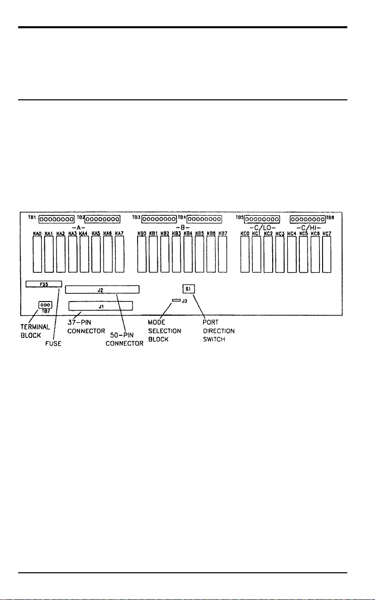
a source of power and the ports to be used. Figure 2-1 shows the location of the Port Direction Switch, in addition to the Terminal Block used
to select the power source.
Figure 2-1. Component locations
2.2 TERMINAL BLOCK TB7
The SSIO-24 draws power from the PC, from an external source, or from
a combination of the two. Factory conÞguration sets the Board for
power from the PC. To conÞgure the power setting, use one of the following procedures.
Setting For PC Power
NOTE: Do not use the PC power setting if the control signals come
from a KPCMCIA-PIO24 module.
INSTALLATION
2 - 1
Page 12

On Terminal Block TB7, connect a jumper wire between the terminals
marked PC and + (the default setting). This setting is shown in
Figure 2-2.
Figure 2-2. The TB7 setting for power from the PC
Setting For External Power Supply
• Control signals come from a standard digital I/O board.
First, remove any jumper wire from TB7. Then, observing polarity,
connect the external power supply to the terminals marked + and -,
as shown in Figure 2-3. Note that failure to observe polarity will
blow Fuse F25.
Figure 2-3. Connecting TB7 for external power when control signals
come from a standard digital I/O board.
• Control signals come from a KPCMCIA-PIO24 module.
The KPCMCIA-PIO24 does not supply +5V to the SSIO-24. Therefore, you must supply all +5V signals externally, including the +5V
that a PC would otherwise supply to the PC terminal on TB7.
On Terminal Block TB7, connect a jumper wire between the terminals marked PC and + (the default setting). See Figure 2-4.
2 - 2
SSIO-24 USER GUIDE
Page 13

Figure 2-4. Connecting TB7 for external power when the control
signals come from a KPCMCIA-PIO24 module.
Then observing polarity, connect the external power supply to the
terminals marked + and -, as shown in Figure 2-4. Note that failure
to observe polarity will blow Fuse F25 and may damage the board.
2.3 PORT DIRECTION SWITCH S1
Parallel I/O cards PIO-12, PIO-24, PIO-96, uPIO-12, and uPIO-24 use an
8255 PPI type interface for communications (information on the 8255
PPI is available from Intel). The 8255 PPI is conÞgured as three ports:
two 8-bit ports (Ports A and B) and one 8-bit port usable as two 4-bit
ports (Port C HI/LOW). Each of these 8255 PPI ports corresponds to a
port on the SSIO-24. Port Direction Switch S1 (see Figure 2-1) selects the
direction of each of these ports.
To set the direction for a port, move the corresponding slide of the Port
Direction Switch to the ON or OFF position. For example, inserting
OUTPUT modules in Ports A and C/LO and INPUT modules in Ports B
and C/HI will require the Port Direction Switch to be set a shown in
Figure 2-5.
Figure 2-5. Setting the Port Direction Switch
INSTALLATION
2 - 3
Page 14

2.4 MODE SELECTION BLOCK J3
The SSIO-24 uses a “power-up” circuit to ensure that output modules
will power up in the OFF state when the PC is turned on. This circuit
operates in either the Normal Mode or the Protected Mode, depending
on the setting of Mode Selection Block J3. The two operating modes are
discussed in the subsections that follow.
Normal Mode
J3 = NORM is the factory setting for the Mode Selection Block.
Powering up the PC resets the PIO-XX board, making all outputs of the
PIO-XX board go active HIGH. At the time a PIO-XX port is
programmed for output, all the lines of that port go inactive LOW. The
SSIO-24 monitors this transition from a logic HIGH level to a logic
LOW level at the Þrst bit of each of the four (4) ports. As soon as the
SSIO-24 detects this transition at a port, it enables the OUTPUT
modules connected to that port. INPUT modules are always enabled
(SW1 setting = INPUT). The SSIO-24 must detect this HIGH to LOW
transition for the OUTPUT modules to become enabled.
Two anomalies exist with NORMAL mode because a reset line to the
SSIO-24 is unavailable. The anomalies are obvious only when using
OUTPUT modules.
After a PIO port is programmed for OUTPUT and the reset button of
the PC is pushed, ALL OUTPUT MODULES GO ACTIVE. This
activation is a potential problem for applications sensitive to such an
event. Either use a
+ [Delete] on the PC) or a
third alternative is explained under
warm reset
cold reset
(by simultaneously pressing [Ctrl] + [Alt]
(turn off the PC, then restart it). A
Protected Mode
, below.
When powering down the PC after the OUTPUT modules are enabled,
the OUTPUT modules become ACTIVE for several milliseconds before
being shut down by the absence of power. This event can be annoying
or potentially dangerous, based on the application. If this behavior is
unacceptable, refer to the
2 - 4
SSIO-24 USER GUIDE
Protected Mode
, below.
Page 15

Protected Mode
This mode is active when J3 = PROT.
In Protected Mode, the SSIO-24 responds to a PC power-down or reset
by keeping the OUTPUT modules deactivated. As with Normal Mode,
INPUT modules are not a problem and are not affected by this mode. In
order to sense a reset at the PC, one of the 24 lines from a PIO-XX must
be sacriÞced. This leaves 23 of the 24 module locations for normal use.
The module location sacriÞced is KC7. THIS MODE REQUIRES PORT
C/HI TO BE SET FOR OUTPUT ONLY AND MODULE LOCATION
KC7 TO BE UNUSED.
This mode works by sensing the Port C7 line of a PIO-XX board. When
this bit is high, the SSIO-24 is RESET. When this bit is low, the RESET to
the SSIO-24 is removed (NOTE: you must wait a minimum of 200 ms
after removal of the SSIO-24 RESET before enabling the OUTPUT
ports). Whenever the PC resets the PIO-XX board, this bit goes high and
automatically resets the SSIO-24 at the same time the PIO-XX board is
reset. This bit also allows you to quickly shut down the entire SSIO-24
with a single write to this location.
The SSIO-24 has a latch for each of the four (4) ports; the latch disables
OUTPUT modules after a reset. After you reset the SSIO-24 by writing a
one (1) to location C7 of PORT C, you may remove the RESET by
writing a zero (0) to location C7 of PORT C. In order to enable the
OUTPUT modules, you must clear each latch associated with an
OUTPUT port. You may clear the latches by writing zeros to each
OUTPUT port to clear the port and writing ones to the OUTPUT ports
followed by writing zeros to the OUTPUT ports to clear the latch with
the HIGH-to-LOW transition. All OUTPUT ports will now be enabled
(NOTE: you must wait a minimum of 200 ms after removal of the
SSIO-24 reset before enabling the OUTPUT ports).
INSTALLATION
2 - 5
Page 16

Example in BASIC
This example assumes Port A is set for OUTPUT modules.
1. Reset SSIO-24.
OUT(BASEADDRESS+2), &H80 'Write 1 to C7
2. Remove Reset.
OUT(BASEADDRESS+2), &H00 'Write 0 to C7
3. 200 ms minimum delay.
FOR I=0 TO 1000 'Delay Before Enabling
'OUTPUT Ports
NEXT I
(NOTE: The upper value of this loop is machine and language
dependent. If the value used doesn’t work, use a larger one.)
4. Clear Output Port A.
OUT(BASEADDRESS+0), &H0 'Write 0s to Port A
5. Set Output Port A.
OUT(BASEADDRESS+0), &HFF 'Write 1s to Port A
6. Clear Output Port A and enable OUTPUT Modules.
OUT(BASEADDRESS+0), &H00 'Write 0s to Port A
7. Output modules are now ready to accept user input...
NOTE: After the computer has been powered-up or after the RESET
button of the computer has been pressed AND the PIO-XX
has been set for the appropriate port directions, the user must
initiate steps 5 and 6 of the above example BEFORE writing to
OUTPUT modules of the SSIO-24.
2.5 INSTALLATION
The SSIO-24 mounts on a ßat panel or other ßat surface, or it installs
in an external rack-type enclosure (such as the Keithley RMF-06 or
RTT-02). Rack-type enclosures require an adapter such as the Keithley
RMT-02. If the SSIO-24 is to be externally mounted, follow steps 1
through 5 as outlined below. Then, install the SSIO-24 into the rack (or
on a ßat surface) and proceed with the remaining steps.
2 - 6
SSIO-24 USER GUIDE
Page 17

1. Install a Parallel I/O board (refer to its user guide for installation
instructions). Be sure to assign it a Base Address.
2. ConÞgure Terminal Block TB7 for the appropriate source of power
(see Section 2.2).
3. Set the Port Direction Switch (see Section 2.3).
4. Plug your selection of input/output modules into locations
KA0-KA7, KB0-KB7, and/or KC0-KC7.
5. Make external connections to the appropriate I/O terminal blocks
(TB1 and TB2 for Port A, TB3 and TB4 for Port B, TB5 for Port C/LO
and TB6 for Port C/HI).
WARNING
If using DC modules, observe the polarity markings at each
terminal location.
6. Install the Hold-Down Bracket.
7. Plug the Parallel I/O card into your computer and connect it to the
SSIO-24 with the appropriate cable. For the PIO-12, PIO-24,
uPIO-12, or uPIO-24 plug the C-18xx cable into SSIO-24 Connector
J1. For the PIO-96, plug the CACC-2000 cable into SSIO-24
Connector J2.
You are now ready to program the Parallel I/O card’s ports to
correspond with those on the SSIO-24. Be very careful to observe the
direction of the ports on the SSIO-24 (refer to the Port Direction Switch).
For example, if Port A on the SSIO-24 is set for INPUT, then Port A on
the Parallel I/O card must be set for INPUT.
WARNING
Setting corresponding ports on the Parallel I/O Card and
the SSIO-24 for opposing directions (Port A on the Parallel
I/O Card for input and Port A on the SSIO-24 for output)
could result in permanent damage to the Parallel I/O card
and the SSIO-24.
INSTALLATION
2 - 7
Page 18

2.6 CONNECTOR PIN ASSIGNMENTS
All digital I/O is through a standard 37-pin D-type male connector or
through a 50-pin PIO-96 type connector. The connector pin assignments
are shown in Figures 2-6 and 2-7.
2 - 8
Figure 2-6. 37-pin connector assignments
SSIO-24 USER GUIDE
Page 19

Figure 2-7. 50-pin connector assignments
■
■ ■
INSTALLATION
2 - 9
Page 20

Chapter 3 /
PROGRAMMING :
3.1 OVERVIEW
The Parallel I/O board uses an 8255 PPI type interface for parallel
communications (a complete description of this device is available from
Intel). The 8255 PPI is divided into two &bit ports (Ports A and B) and
one S-bit port
port of the 8255 PPI corresponds to a port on the SSIO-24.
The 8255 PPI has three modes of operation (Mode 1, Mode 2, and Mode
3). When using a Parallel l/O board with the SSIO-24, use the 8255 PPI
in Mode 0 only. The port direction and mode are set by writing to the
8255 control register (Parallel l/O board Base Address +3).
3.2 EXAMPLES In C
that
is usable as two 4-bit ports (Port C HI/LO). Each
This example in C assumes that Ports A and C/LO (KAO-KA7 and
KCO-KC3) are for output while Ports B and C/HI are for input.
1. Write to
the
control register to set Ports A and C/LO to output
and Ports B and C/l-E to input. For example,
outp (Base-addre8~+3,0%8A) ;
2. Access the ports as needed. For example, to write to Port A,
outp (Barre-addreswt0, port-a-data) ;
3. To write to Port C/LO,
outp(Ease_addresst2,port_o~o_data);
PROGRAMMING 3 - I
Page 21

4. To read Port B,
port-b=inp
(Base-addreestl);
5. To read Port C/HI,
port a hi=inp(Base_addre68+2)>>4;
--
In BASIC
This example in BASIC performs the same functions as the example in
C. Again, assume Ports A and C/LO (KAO-KA7 and KCO-KC31 are for
output while Ports B and C/HI are for input.
1. Write to the control register to set Ports A and C/LO to output
and
Ports B and
2. Access the ports as needed. For example, to write to Port A,
C/l-U to input. For example,
0DT(BASEADDRE88+3),LIi8A
OUT(BASEADDRE88tO),RORTADATA
3.
To write to Port C/LO,
OUT(BASWkDDRESS+2),PORTCLODATA
4. To read Port B,
PORTB%=INP(BASEADDRESStl)
5. To read Port C/HI,
PORTCHI%=INR(BASEADDRESSt2)\16
* THE '\lS' PERFORMS A SHIFT RIGHT BY 4 POSITIONS
rnMN
3-2
SSIO-24 USERGUIDE
Page 22

Chapter
FACTORY RETURNS
4.1 FUSE REPLACEMENT
Fuse F25, located as shown in Figure 2-1, will blow if the polarity of
external power supply connections does not match that of TB7. A
replacement fuse may be any standard 3AG, 250 V, 1 A, fast-blow fuse.
4.2 RETURN REQUIREMENTS
Before returning any equipment for repair, please call 508/880-3000 to
notify MetraByte’s technical service personnel. If possible, a technical
representative will diagnose and resolve your problem by telephone.
a resolution of your problem by telephone is not possible, the technical
representative will issue you a Return Material Authorization (RMA)
number and ask you to return the equipment. Please reference the
RMA number in any documentation regarding the equipment and on
the outside of the shipping container.
4
If
Note that if you are submitting your equipment for repair under
warranty, you must furnish the invoice number and date of purchase.
When returning equipment for repair, please include the following
information:
1. Your name, address, and telephone number.
2. The invoice number and date of equipment purchase.
3. A description of the problem or its symptoms.
4. Be sure to reference the RMA number on the outside of the
package!
Repackage the equipment. Handle it with ground protection; use antistatic wrapping, if possible.
FACTORY RETURNS
4 - 1
Page 23

Ship the equipment to:
Attn: RMA #___________
Repair Department
Keithley Instruments, Inc.
28775 Aurora Road
Cleveland, OH 44139
Telephone 1-888-KEITHLEY
FAX (440) 248-6168
■ ■ ■
4 - 2
SSIO-24 USER GUIDE
Page 24

Specifications are subject to change without notice.
All Keithley trademarks and trade names are the property of Keithley Instruments, Inc. All other
trademarks and trade names are the property of their respective companies.
Keithley Instruments, Inc.
28775 Aurora Road • Cleveland, Ohio 44139
440-248-0400 • Fax: 440-248-6168
1-888-KEITHLEY (534-8453) www.keithley.com
© Copyright 2000 Keithley Instruments, Inc. No. 2193
Printed in the U.S.A. 4/2001
 Loading...