

Page 1

•
•
Keithley Instruments, Inc.
28775 Aurora Road
Cleveland, Ohio 44139
(440) 248-0400
Fax: (440) 248-6168
State I/O Module Accessory Board
Packing List Manual
Introduction
Model SRA-01 8-Channel Solid-
This document provides safety information, installation instructions, and specifications for the Keithley Model SRA-01 8-Channel solid-state I/O-module accessory board.
Description
The SRA-01 interfaces full-size, industry-standard digital I/O modules to a variety of digital I/O and combined analog/digital
I/0 boards. The digital I/O modules allow the board to sense AC and DC signals and switch AC and DC loads. The SRA-01 is
compatible with the following Keithley boards:
Digital I/O boards: KPCI-3160, KPCI-PIO96, PIO-96J, PIO-12/24, KPCI-PIO24, and KPCMCIA-PIO24
Combined analog/digital I/0 boards: KPCI-3107/3108, DAS-1600/1200, and DASCON-1
Four types of modules can be used with the SRA-01: DC input, DC output, AC input, and AC output. Sockets K1 through K4
of the SRA-01 accommodate any combination of input or output modules. (A switch for each socket configures it as either an
input-module socket or as an output-module socket.) Sockets K5 through K8 accommodate four output modules, only. If you
connect a PIO-12/24 to the SRA-01, socket K9 accommodates an additional input module to isolate an interrupt signal source
from the PIO-12/24 interrupt input.
LEDs monitor all module activity.
Safety summary
WARNING
This product is intended for use by qualified personnel who recognize shock hazards and are familiar with the safety precautions
required to avoid possible injury. Read the operating and safety information carefully before using the product.
Users of this product must be protected from electric shock at all times. The responsible body must ensure that users are prevented access and/or insulated from every connection point.
Do not connect switching cards directly to unlimited power circuits. When connecting sources to switching cards, install protective devices to limit fault current and voltage to the card.
Read and follow the “Safety Precautions” discussed at the end of this manual.
Installation
WARNING
CAUTION
Users of this product must be protected from electric shock at all times. The responsible
body must ensure that users are prevented access and/or insulated from every connection
point. In some cases, connections must be exposed to potential human contact. Product
users in these circumstances must be trained to protect themselves from the risk of electric shock. If the circuit is capable of operating at or above 1000 volts, no conductive part
of the circuit may be exposed.
Ensure that the computer power is turned OFF before installing the SRA-01. Connecting the SRA-01 to the computer while the power is ON can damage your computer, the
accessory, or both.
PA-639 Rev. F / 6-02
Page 2

2
1 3
1. Shut down and turn OFF your computer.
2. Install input modules, output modules, or a mixture of input and output modules in sockets K1 through K4.
3. Set switches S1 through S4 to “IN” or “OUT” to match the type of modules installed in sockets K1 through K4. Refer to
Table 1.
NOTE
Table 1
Module, switch, port, and connector-pin correspondence for module sockets K1 through K9
Corresponding
Module
socket
K1 S1 Input IN PC3 26
K2 S2 Input IN PC2 27
K3 S3 Input IN PC1 28
K4 S4 Input IN PC0 29
K5 Not applicable Output only Not applicable PB3 7
K6 Not applicable Output only Not applicable PB2 8
K7 Not applicable Output only Not applicable PB1 9
K8 Not applicable Output only Not applicable PB0 10
K9 Not applicable Input only Not applicable Interrupt input of
I/O selection
switch
If any of sockets K1 through K4 are not used, set the corresponding switches to OUT.
Module type
that is
installed in
socket
Output OUT PB7 3
Output OUT PB6 4
Output OUT PB5 5
Output OUT PB4 6
Required I/O
switch setting
I/O port bit that
is connected to
module
PIO-12 and PIO24, only
Pin of 37-pin D
connector that
is connected to
module
4. Install output modules, only, in sockets K5 through K8.
5. If you have connected the SRA-01 to a PIO-12 or PIO-24 board and will be processing data via interrupts, then optionally
install an input module in socket K9 to isolate your interrupt signal source from the PIO-12/24 interrupt input.
WARNING
6. Connect your digital I/O board to the SRA-01 37-pin D connector, using available cables and accessories, as shown in
Figure 1.
If you make your own cables, use a standard 37-pin female D connector (Keithley part number SFC-37). Refer to Figure 2
and Table 1 for pin assignments.
Install a module in socket K9 only if you have connected the SRA-01 to a PIO-12,
PIO-24, KPCI-PIO24, or KPCMCIA-PIO24 board. Otherwise, a potentially damaging
signal could be connected to pin 1 of the 37-pin D connector.
Page 3
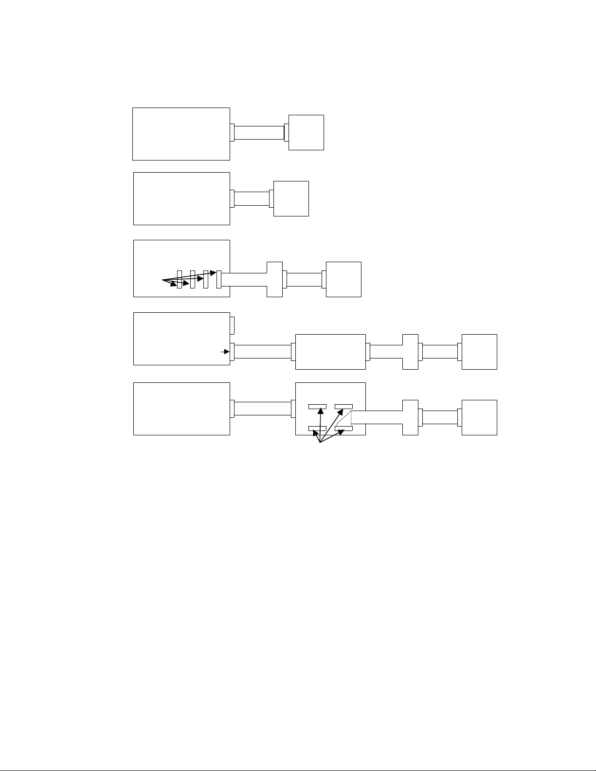
Figure 1
Connecting the SRA-O1 to digital I/O and combined analog/digital I/O boards.
KPCMCIA-PIO24
Board
DASCON-1,
PIO-12/24, KPCI-PIO24
or DAS-1600/1200 Board
(At aux. connector of
DAS-1600/1200)
PIO-96J or
KPCI-PIO96 Board
Any of
these
KPCI-3107 or KPCI-3108
Board
(Digital I/O Connector)
KPCI-3160 Board
SRA-01KCAB-PIO
SRA-01C-1800
CAB-1284CC STA-3108-D1 SRA-01ADP-5037 C-1800
CONN-3160-D1
CAB-1800
NOTE: KCAB-PIO cable is included
with KPCMCIA-PIO24 board
SRA-01ADP-5037 C-1800
SRA-01ADP-5037 C-1800
Any of
these
7. Wire external circuits to the screw terminals, using 12-22 AWG wire. For terminal/pin/port correspondence refer to
Table 1, to Figure 2, to your I/O-board manual, and to manuals for accessories used to connect the board to the SRA-01.
WARNING
Exercise extreme caution when a shock hazard is present. Lethal voltage may be present
on cable connector jacks or test fixtures. The American National Standards Institute
(ANSI) states that a shock hazard exists when voltage levels greater than 30V RMS,
42.4V peak, or 60VDC are present. A good safety practice is to expect that hazardous
voltage is present in any unknown circuit before measuring.
Hazardous rated circuits must be provided with external double insulation or reinforced
insulation. Do not place accessible non-hazardous I/O modules next to hazardous I/O
modules. Refer to the isolation diagram, Figure 4, and to the section “Safety
Precautions.”
Page 4

4
Figure 4 illustrates an AC output application and an AC input application.
Figure 2
Pin assignments for the 37-pin D connector
PB PORT
IRQ_IN
DIG COM
PB0
PB1
PB2
PB3
PB4
PB5
PB6
PB7
19
18
17
16
15
14
13
12
11
10
9
8
7
6
5
4
3
2
1
Top View
37
36
35
34
33
32
31
30
29
28
27
26
25
24
23
22
21
20
Figure 3
SRA-01 electrical-isolation diagram
SRA-01 board
At 37-pin D
connector
Through I/O
modules
PC0
PC1
PC2
PC3
+5V
NOTE: IRQ_IN is the only valid for connections
to PIO-12, PIO-24, KPCI-PIO24, and
KPCMCIA-PIO24.
PC PORT
Between
terminal-
block
terminals
Computer circuits Module at K1
NON-HAZARDOUS — — Isolation A *— — Isolated I/O — —USER-supplied wiring
|
Isolation B **
Computer circuits Module at K2
|
NON-HAZARDOUS — — Isolation A — — Isolated I/O — —USER-supplied wiring
|
Isolation B
Computer circuits Module at K3
|
NON-HAZARDOUS — — Isolation A — — Isolated I/O — —USER-supplied wiring
|
•••
•••
•••
|
Isolation B
Computer circuits Module at K8
|
NON-HAZARDOUS — — Isolation A — — Isolated I/O — —USER-supplied wiring
|
Isolation B
Computer circuits Module at K9
|
NON-HAZARDOUS — — Isolation A — — Isolated I/O — —USER-supplied wiring
*
Isolation A, per EN61010-1:1995, = DOUBLE INSULATION, 300V, CAT II, pollution degree 2
**
Isolation B, per EN61010-1:1995, ≥ BASIC INSULATION, 300V, CAT II, pollution degree 2
Page 5

Figure 4
Examples of SRA-01 applications
5
Contolling AC Voltage
Use with
OAC-05
module to
control
120VAC
Pin # on
D connection
Sensing AC Voltage
Use with
IAC-05
module to
sense
120VAC
Pin # on
D connection
PC0 pin 29 go “LOW”
+5V
DIG COM
PB5
A “LOW” here
turns off load
+5V
DIG COM
PC0
AC sensed makes
LED “ON” when load is energized
20
11
5
Screw terminals
+-
labeled PB5/PC1
User
load
Current
limit
device
120VAC
source
(energized
terminal)
LED “ON” when AC signal sensed
20
11
29
Screw terminals
+-
labeled PB4/PC0
Current
limit
device
120VAC
signal
120VAC
return
(neutral
terminal)
120VAC
return
(neutral)
OAC-05
module in
socket K3
IAC-05
module in
socket K4
OUT
IN
OUT
IN
Module I/O
selection switch
S3 “OUT”
Module I/O
selection switch
S4 “IN”
8. Turn ON and reboot your computer.
9. Configure the ports of your digital I/O board or analog/digital I/O board, using your application software. (If your board is
a KCPI-3160, KPCI-PIO96, or PIO-96J, configure the ports of the connected port group.) Configure PB01 through PB07
as outputs and PC0 through PC3 as inputs.
NOTE
When the SRA-01 is used with output modules, the output modules will be ON by default
whenever the computer system is reset or powered up, until your application program is initialized and can turn them off. Users are advised to allow for this in their system design by
either not connecting any loads that would be dangerous to have energized at that time, or by
providing another means of switching the power supply feed to those devices.
An alternate method for advanced users would be to change the 74240 chip in the SRA-01
board to a 74244 chip. All output bits will be inverted, and the default state will be OFF.
This also inverts the bits during operation and must be taken into account during programming. This is considered a non-standard configuration and is not supported by Keithley Instruments.
Page 6

Specifications
Hardware
Number of I/O modules:
Module type:
Logic Level to turn "ON" module:
Logic level to turn "OFF" module:
LEDs:
Environmental
Operating temperature range:
Storage temperature range:
Humidity:
Power consumption
Board only:
With modules:
Physical
Dimensions (with enclosure):
Screw terminal sizes:
9 max
Solid state, standard (full) size
"1" (high)
"0" (low)
8 Red for output modules, 5 Yellow for input modules
0° to 60°C
-40° to +100°C
0 to 90% Non-condensing
+5 Volts 39mA typical
100mA typical
6.687 in. L x 5.125 in. W x 2.375 in. H
(17cm L x 13.0cm W x 6cm H)
12–22 AWG
Compatible I/O modules
Input modules
IDC-05 IAC-05* IAC5A*
Nominal voltage 5-28VDC 120VAC/VDC 240VAC
Max input current 34mA 5mA RMS 5mA RMS
Max turn ON time 1.0ms 20ms 20ms
Max turn OFF time 1.0ms 30ms 30ms
Output modules
OAC5A or
ODC-05 ODC5A* OAC-05*
Nominal output voltage 5-48VDC 5-150VDC 120VAC 240VAC
Max load current 3.0A ** 1.0A 3.5A RMS 3.5A RMS
Max drive current 18mA 18mA 20mA 20mA
Response time 100µs (on)
750µs (off)
* Hazardous rated circuits must be provided with external double insulation or reinforced insulation. Do not place accessible non-hazardous I/O
modules next to hazardous I/O modules. Refer to the isolation block diagram and the safety precautions.
**External fuse required. 5A Littlefuse part number 217005 or equivalent.
100µs (on)
750µs (off)
0.5 cycle
(on/off)
SM-OAC5A*
0.5 cycle
(on/off)
6
Page 7

afety Precautions
S
The following safety precautions should be observed before using this product and any associated instrumentation. Although some instruments and accessories would normally be used with non-hazardous voltages, there are situations where hazardous conditions may be present.
This product is intended for use by qualified personnel who recognize shock hazards and are familiar with the safety precautions required to
avoid possible injury. Read and follow all installation, operation, and maintenance information carefully before using the product. Refer to
the manual for complete product specifications.
If the product is used in a manner not specified, the protection provided by the product may be impaired.
The types of product users are:
Responsible body is the individual or group responsible for the use and maintenance of equipment, for ensuring that the equipment is operated
within its specifications and operating limits, and for ensuring that operators are adequately trained.
Operators use the product for its intended function. They must be trained in electrical safety procedures and proper use of the instrument. They
must be protected from electric shock and contact with hazardous live circuits.
Maintenance personnel perform routine procedures on the product to keep it operating properly, for example, setting the line voltage or re-
placing consumable materials. Maintenance procedures are described in the manual. The procedures explicitly state if the operator may perform them. Otherwise, they should be performed only by service personnel.
Service personnel are trained to work on live circuits, and perform safe installations and repairs of products. Only properly trained service
personnel may perform installation and service procedures.
Keithley products are designed for use with electrical signals that are rated Installation Category I and Installation Category II, as described
in the International Electrotechnical Commission (IEC) Standard IEC 60664. Most measurement, control, and data I/O signals are Installation
Category I and must not be directly connected to mains voltage or to voltage sources with high transient over-voltages. Installation Category
II connections require protection for high transient over-voltages often associated with local AC mains connections. Assume all measurement,
control, and data I/O connections are for connection to Category I sources unless otherwise marked or described in the Manual.
Exercise extreme caution when a shock hazard is present. Lethal voltage may be present on cable connector jacks or test fixtures. The American National Standards Institute (ANSI) states that a shock hazard exists when voltage levels greater than 30V RMS, 42.4V peak, or 60VDC
are present. A good safety practice is to expect that hazardous voltage is present in any unknown circuit before measuring.
Operators of this product must be protected from electric shock at all times. The responsible body must ensure that operators are prevented
access and/or insulated from every connection point. In some cases, connections must be exposed to potential human contact. Product operators in these circumstances must be trained to protect themselves from the risk of electric shock. If the circuit is capable of operating at or
above 1000 volts, no conductive part of the circuit may be exposed.
Do not connect switching cards directly to unlimited power circuits. They are intended to be used with impedance limited sources. NEVER
connect switching cards directly to AC mains. When connecting sources to switching cards, install protective devices to limit fault current and
voltage to the card.
Before operating an instrument, make sure the line cord is connected to a properly grounded power receptacle. Inspect the connecting cables,
test leads, and jumpers for possible wear, cracks, or breaks before each use.
When installing equipment where access to the main power cord is restricted, such as rack mounting, a separate main input power disconnect
device must be provided, in close proximity to the equipment and within easy reach of the operator.
For maximum safety, do not touch the product, test cables, or any other instruments while power is applied to the circuit under test. ALWAYS
remove power from the entire test system and discharge any capacitors before: connecting or disconnecting cables or jumpers, installing or
removing switching cards, or making internal changes, such as installing or removing jumpers.
Do not touch any object that could provide a current path to the common side of the circuit under test or power line (earth) ground. Always make measurements with dry hands while standing on a dry, insulated surface capable of withstanding the voltage being measured.
The instrument and accessories must be used in accordance with its specifications and operating instructions or the safety of the equipment
may be impaired.
Do not exceed the maximum signal levels of the instruments and accessories, as defined in the specifications and operating information, and
as shown on the instrument or test fixture panels, or switching card.
When fuses are used in a product, replace with same type and rating for continued protection against fire hazard.
Chassis connections must only be used as shield connections for measuring circuits, NOT as safety earth ground connections.
If you are using a test fixture, keep the lid closed while power is applied to the device under test. Safe operation requires the use of a lid interlock.
7
Page 8

If or is present, connect it to safety earth ground using the wire recommended in the user documentation.
!
The symbol on an instrument indicates that the user should refer to the operating instructions located in the manual.
The symbol on an instrument shows that it can source or measure 1000 volts or more, including the combined effect of normal and common mode voltages. Use standard safety precautions to avoid personal contact with these voltages.
The WARNING heading in a manual explains dangers that might result in personal injury or death. Always read the associated information
very carefully before performing the indicated procedure.
The CAUTION heading in a manual explains hazards that could damage the instrument. Such damage may invalidate the warranty.
Instrumentation and accessories shall not be connected to humans.
Before performing any maintenance, disconnect the line cord and all test cables.
To maintain protection from electric shock and fire, replacement components in mains circuits, including the power transformer, test leads,
and input jacks, must be purchased from Keithley Instruments. Standard fuses, with applicable national safety approvals, may be used if the
rating and type are the same. Other components that are not safety related may be purchased from other suppliers as long as they are equivalent
to the original component. (Note that selected parts should be purchased only through Keithley Instruments to maintain accuracy and functionality of the product.) If you are unsure about the applicability of a replacement component, call a Keithley Instruments office for information.
To clean an instrument, use a damp cloth or mild, water based cleaner. Clean the exterior of the instrument only. Do not apply cleaner directly
to the instrument or allow liquids to enter or spill on the instrument. Products that consist of a circuit board with no case or chassis (e.g., data
acquisition board for installation into a computer) should never require cleaning if handled according to instructions. If the board becomes
contaminated and operation is affected, the board should be returned to the factory for proper cleaning/servicing.
8
 Loading...