

Tektronix SRA-01 User manual

•
•
Keithley Instruments, Inc.
28775 Aurora Road
Cleveland, Ohio 44139
(440) 248-0400
Fax: (440) 248-6168
State I/O Module Accessory Board
Packing List Manual
Introduction
Model SRA-01 8-Channel Solid-
This document provides safety information, installation instructions, and specifications for the Keithley Model SRA-01 8-Channel solid-state I/O-module accessory board.
Description
The SRA-01 interfaces full-size, industry-standard digital I/O modules to a variety of digital I/O and combined analog/digital
I/0 boards. The digital I/O modules allow the board to sense AC and DC signals and switch AC and DC loads. The SRA-01 is
compatible with the following Keithley boards:
Digital I/O boards: KPCI-3160, KPCI-PIO96, PIO-96J, PIO-12/24, KPCI-PIO24, and KPCMCIA-PIO24
Combined analog/digital I/0 boards: KPCI-3107/3108, DAS-1600/1200, and DASCON-1
Four types of modules can be used with the SRA-01: DC input, DC output, AC input, and AC output. Sockets K1 through K4
of the SRA-01 accommodate any combination of input or output modules. (A switch for each socket configures it as either an
input-module socket or as an output-module socket.) Sockets K5 through K8 accommodate four output modules, only. If you
connect a PIO-12/24 to the SRA-01, socket K9 accommodates an additional input module to isolate an interrupt signal source
from the PIO-12/24 interrupt input.
LEDs monitor all module activity.
Safety summary
WARNING
This product is intended for use by qualified personnel who recognize shock hazards and are familiar with the safety precautions
required to avoid possible injury. Read the operating and safety information carefully before using the product.
Users of this product must be protected from electric shock at all times. The responsible body must ensure that users are prevented access and/or insulated from every connection point.
Do not connect switching cards directly to unlimited power circuits. When connecting sources to switching cards, install protective devices to limit fault current and voltage to the card.
Read and follow the “Safety Precautions” discussed at the end of this manual.
Installation
WARNING
CAUTION
Users of this product must be protected from electric shock at all times. The responsible
body must ensure that users are prevented access and/or insulated from every connection
point. In some cases, connections must be exposed to potential human contact. Product
users in these circumstances must be trained to protect themselves from the risk of electric shock. If the circuit is capable of operating at or above 1000 volts, no conductive part
of the circuit may be exposed.
Ensure that the computer power is turned OFF before installing the SRA-01. Connecting the SRA-01 to the computer while the power is ON can damage your computer, the
accessory, or both.
PA-639 Rev. F / 6-02
2
1 3
1. Shut down and turn OFF your computer.
2. Install input modules, output modules, or a mixture of input and output modules in sockets K1 through K4.
3. Set switches S1 through S4 to “IN” or “OUT” to match the type of modules installed in sockets K1 through K4. Refer to
Table 1.
NOTE
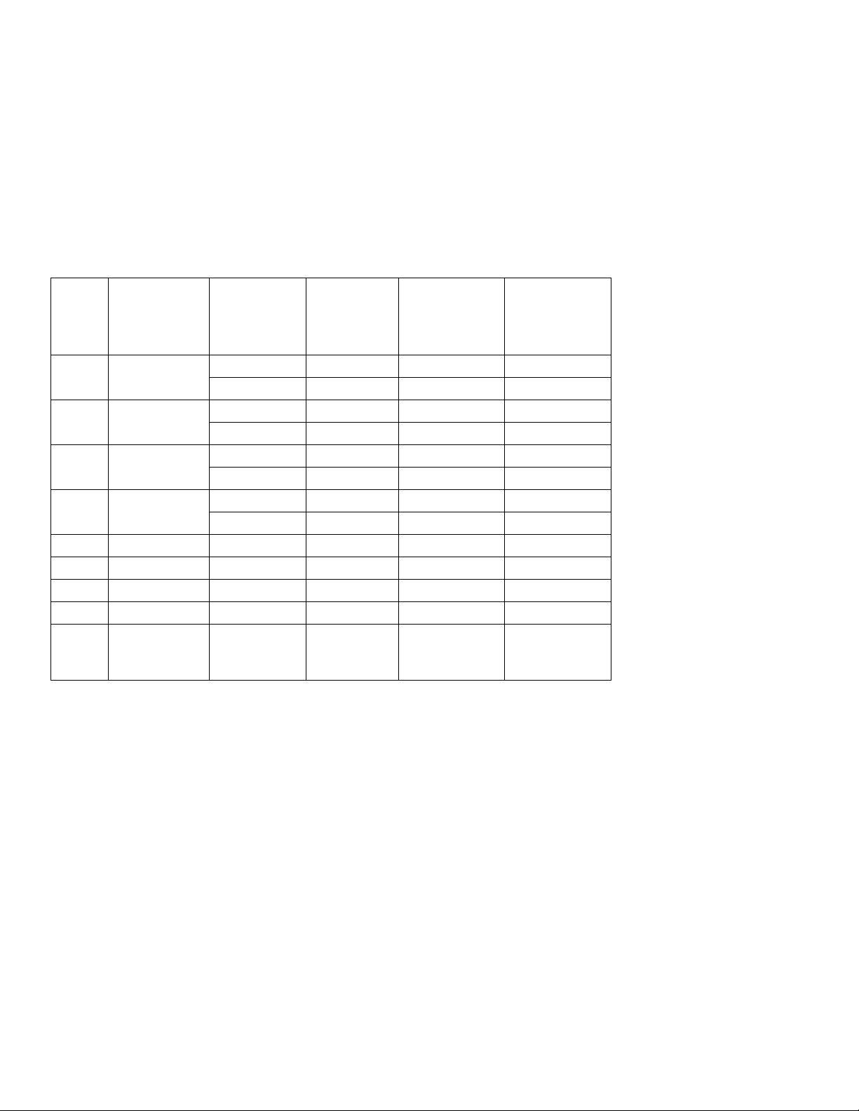
Table 1
Module, switch, port, and connector-pin correspondence for module sockets K1 through K9
Corresponding
Module
socket
K1 S1 Input IN PC3 26
K2 S2 Input IN PC2 27
K3 S3 Input IN PC1 28
K4 S4 Input IN PC0 29
K5 Not applicable Output only Not applicable PB3 7
K6 Not applicable Output only Not applicable PB2 8
K7 Not applicable Output only Not applicable PB1 9
K8 Not applicable Output only Not applicable PB0 10
K9 Not applicable Input only Not applicable Interrupt input of
I/O selection
switch
If any of sockets K1 through K4 are not used, set the corresponding switches to OUT.
Module type
that is
installed in
socket
Output OUT PB7 3
Output OUT PB6 4
Output OUT PB5 5
Output OUT PB4 6
Required I/O
switch setting
I/O port bit that
is connected to
module
PIO-12 and PIO24, only
Pin of 37-pin D
connector that
is connected to
module
4. Install output modules, only, in sockets K5 through K8.
5. If you have connected the SRA-01 to a PIO-12 or PIO-24 board and will be processing data via interrupts, then optionally
install an input module in socket K9 to isolate your interrupt signal source from the PIO-12/24 interrupt input.
WARNING
6. Connect your digital I/O board to the SRA-01 37-pin D connector, using available cables and accessories, as shown in
Figure 1.
If you make your own cables, use a standard 37-pin female D connector (Keithley part number SFC-37). Refer to Figure 2
and Table 1 for pin assignments.
Install a module in socket K9 only if you have connected the SRA-01 to a PIO-12,
PIO-24, KPCI-PIO24, or KPCMCIA-PIO24 board. Otherwise, a potentially damaging
signal could be connected to pin 1 of the 37-pin D connector.
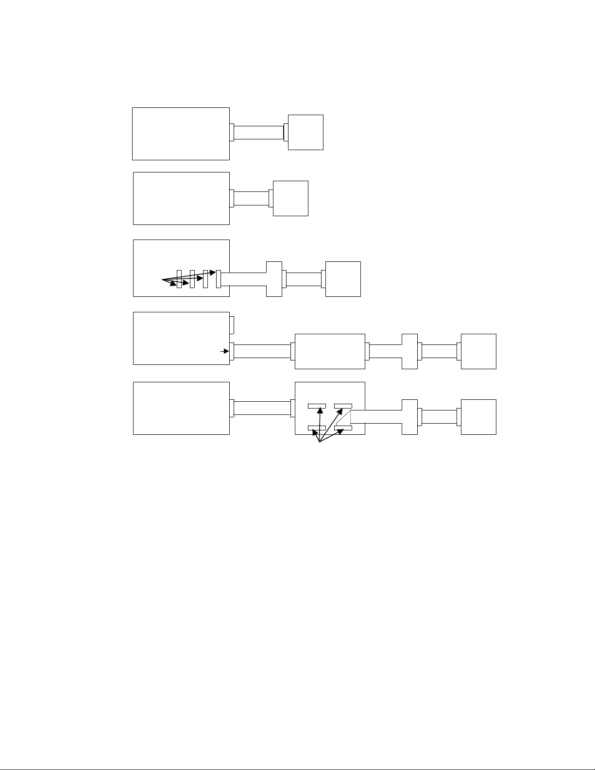
Figure 1
Connecting the SRA-O1 to digital I/O and combined analog/digital I/O boards.
KPCMCIA-PIO24
Board
DASCON-1,
PIO-12/24, KPCI-PIO24
or DAS-1600/1200 Board
(At aux. connector of
DAS-1600/1200)
PIO-96J or
KPCI-PIO96 Board
Any of
these
KPCI-3107 or KPCI-3108
Board
(Digital I/O Connector)
KPCI-3160 Board
SRA-01KCAB-PIO
SRA-01C-1800
CAB-1284CC STA-3108-D1 SRA-01ADP-5037 C-1800
CONN-3160-D1
CAB-1800
NOTE: KCAB-PIO cable is included
with KPCMCIA-PIO24 board
SRA-01ADP-5037 C-1800
SRA-01ADP-5037 C-1800
Any of
these
7. Wire external circuits to the screw terminals, using 12-22 AWG wire. For terminal/pin/port correspondence refer to
Table 1, to Figure 2, to your I/O-board manual, and to manuals for accessories used to connect the board to the SRA-01.
WARNING
Exercise extreme caution when a shock hazard is present. Lethal voltage may be present
on cable connector jacks or test fixtures. The American National Standards Institute
(ANSI) states that a shock hazard exists when voltage levels greater than 30V RMS,
42.4V peak, or 60VDC are present. A good safety practice is to expect that hazardous
voltage is present in any unknown circuit before measuring.
Hazardous rated circuits must be provided with external double insulation or reinforced
insulation. Do not place accessible non-hazardous I/O modules next to hazardous I/O
modules. Refer to the isolation diagram, Figure 4, and to the section “Safety
Precautions.”
 Loading...