


xx
SPG8000A
Master Sync / Clock Reference Generator Technical
ZZZ
Reference
User Manual
*P077121600*
077-1216-00


xx
SPG8000A
ZZZ
Master Sync / Clock Reference Generator Technical Reference
User Manual
Register now!
Click the following link to protect your product.
► www.tek.com/register
This document supports firmware version 3.0 and above.
www.tek.com
077-1216-00

Copyright © Tektronix. All rights reserved. Licensed software products are owned by Tektronix or its subsidiaries
or suppliers, and are protected by national copyright laws and international treaty provisions.
Tektronix products are covered by U.S. and foreign patents, issued and pending. Information in this publication
supersedes that in all previously published material. Specifications and price change privileges reserved.
TEKTRONIX and TEK are registered trademarks of Tektronix, Inc.
Contacting Tektronix
Tektronix, Inc.
14150 SW Karl Braun Drive
P.O. B o x 500
Beaverto
USA
For product information, sales, service, and technical support:
n, OR 97077
In North America, call 1-800-833-9200.
Worldwide, visit www.tek.com to find contacts in your area.

Table of Contents
Important safety information..... ................................ ................................ ................. x
General safety summary ...................................................................................... x
Service safety summary.............. ................................ ................................ ....... xii
Terms in this manual ............... .................................. ................................ ....... xiii
Symbols and terms on the product ......................................................................... xiii
Preface .............................................................................................................. xv
Product description ................... ................................ .................................. ...... xv
Methods of operation. .................................. ................................ ................... xviii
Product documentation........... ................................ ................................ ........... xix
System timing....................................................................................................... 1
Frame reset signals ..................... ................................ ................................ ....... 1
GPS and GLONASS signal quality (Option GPS only) . . ... . . ..... . ..... . ... . . ..... . ..... . .... . ..... . .... 2
Time flow block diagram ........ ................................ .................................. ........... 5
Web user interface ................................................................................................. 11
Operational considerations................................................................................... 11
Elements of the Web user interface ......................................................................... 12
SNMP remote control... .................................. ................................ ........................ 15
SNMP configuration.......................................................................................... 15
Download the MIB ........................................................................................... 16
How to backup/restore presets and user data ....................... ................................ ............ 17
How the backup and restore operations work ............................................................. 17
Memory requirements........................................................................................ 18
Backup/restore procedure ................................ .................................. .................. 19
How to transfer or install user files .............................................................................. 21
To transfer or install user files using FTP ...................... .................................. .......... 21
To transfer or install user files using a USB drive..................... ................................ .... 23
How to upgrade the instrument firmware ....................................................................... 27
Determine if a firmware upgrade is needed ................................................................ 27
Firmware upgrade overview................................................................................. 29
USB firmware upgrade................. ................................ ................................ ...... 29
Network firmware upgrade .................................................................................. 32
Verify the firmware upgrade and reinstall user files ...................................................... 34
Firmware upgrade troubleshooting ............... .................................. ........................ 34
How to operate an instrument with two power supplies (Option DPW only) ................ .............. 36
Power supply status........................................................................................... 36
To con figure the preferred (active) supply ................................................................. 37
To hot-swap a Power Supply module....................................................................... 39
How to use Stay Genlock
About Stay Genlock
®
®
....................................................................................... 41
......................................................................................... 41
SPG8000A User Manual i

Table of Contents
To enable Stay G
AES menu .......................................................................................................... 43
Global Settings . ..... . ..... . ..... . ..... . ..... . ..... . ..... . . .... . . .... . . .... . . .... . . .... . . .... . . .... . . ... . . . .... 44
Channel Parameters................................... ................................ ........................ 45
AES menu factory default settings.... . ..... . ... . . ..... . ..... . ..... . ..... . ..... . ... . . . .... . ..... . ..... . ..... 46
Black menu........... ................................ .................................. ............................ 47
Black Output settings.. . ..... . ..... . ..... . ..... . ..... . ..... . ..... . ..... . ..... . ..... . ..... . ..... . ..... . ..... . .. 48
Black Timing settings .... . . .... . . .... . ..... . ..... . ..... . ..... . ..... . ..... . ..... . ..... . ... . . ..... . ..... . ..... . 49
Black Timecode settings . ..... . ... . . . .... . ..... . ..... . ... . . ..... . ..... . .... . ..... . ..... . ..... ..... . ..... . .... 50
Blank On Reference Unlock settings ..... .... . . ..... . ..... . ..... . ..... . ..... . ..... . ..... . .... . . .... . . .... . . 51
HD Tri-level Sync Rate ...... ................................ ................................ ................ 51
Black menu factory default settings ........ ................................ ................................ 52
Composite menu (Option BG only) ............................................................................. 53
Composite output settings ................................................................................... 54
Composite Timing settings .............. ................................ ................................ .... 55
Composite Timecode settings ..... . ..... . ... . . ..... . ..... . ... . . . .... . ..... . ..... . ... . . ..... . ..... . ... . . . .... 55
Composite menu factory default settings .... . ..... . ..... . ..... . ... . . ..... . ..... . ..... . ..... . ... . . . .... . ... 57
Dolby-E Configuration menu (Option DBT only) ............................................................. 59
Dolby-E Channel Configuration ............................................................................ 60
Dolby-E METADATA............................................ ................................ ............ 60
Dolby-E generated formats .................................................................................. 63
Dolby-E Configuration menu factory default settings .............. ................................ ...... 71
Embedded menu (Option SDI only)............................................................................. 73
Embedded menu factory default settings. ..... . ..... . ..... . ..... . ..... . ..... . ..... . ..... . ... . . . .... . . .... . . 76
LTC menu .......................................................................................................... 77
LTC menu factory default settings ..... . ..... . ..... . ..... . ..... . ..... . ..... . ... . . . .... . . .... . . .... . . .... . . .. 78
Reference menu.................................................................................................... 79
Reference settings ............ .................................. ................................ .............. 79
PTP ............................................................................................................. 80
GPS............. ................................ ................................ ................................ 81
Genlock Timing settings . . ..... . ..... . ..... . ..... . ..... . ..... . ..... . ..... . ..... . ..... . ..... . ..... . ..... . ..... 84
Reference menu factory default settings . ..... . ... . . . .... . ..... . ..... . ..... . ..... . ..... . ..... . ... . . ..... . .. 85
SDI menu (Option SDI only)..................................................................................... 87
SDI Signal submenu.......................... .................................. .............................. 88
SDI Configure Zoneplate submenu ..... ................................ .................................. .. 92
SDI Moving Picture submenu....... ................................ ................................ ........ 95
SDI Video submenu .......................................................................................... 96
SDI Overlay submenu........................................................................................ 98
SDI Ancillary Data submenu .... . ..... . ..... . ..... . ..... . ..... . ... . . ..... . ..... . ..... . ..... . .... . . .... . ... 104
SDI Timecode submenu.................................................................................... 109
SDI menu factory default settings .... . . .... . ..... . ..... . ..... . ..... . ... . . ..... . ..... . ..... . ..... . ... . . . .. 111
enlock
®
........................ ................................ ............................ 41
ii SPG8000A User Manual

Table of Contents
How to select an
Test signal sets .... .................................. ................................ ........................ 116
SDI picture file generation................................................................................. 123
SDI Zone plate signals ......... ................................ ................................ ............ 124
Zone plate dependent parameters ......................................................................... 129
Status menu ............ ................................ ................................ .......................... 135
System menu ..................................................................................................... 139
Status submenu.............................................................................................. 141
Presets submenu ............................................................................................ 143
General Settings submenu . . ..... . ..... . ..... . ... . . ..... . ..... . ..... . ..... . ..... . ..... . ..... . ... . . . .... . . .. 144
PTP Network Settings submenu .... . ..... . ... . . ..... . ..... . ... . . . .... . ..... . ..... . ..... . ... . . ..... . ..... . 145
SNMP Settings submenu. . ..... ..... . ..... . ..... . ..... . ..... . ..... . ..... . ..... . ... . . . .... . . .... . ..... . ..... 146
GPI Settings submenu . ..... . ..... . ..... . ..... . ..... . ... . . ..... . ..... . ..... . ..... . ..... . ..... . ..... . ..... . .. 149
Options submenu ............. ................................ .................................. ............ 152
Diagnostics submenu ....................................................................................... 153
System menu factory default settings..................................................................... 161
Time menu............ .................................. ................................ .......................... 163
Time of Day submenu...................................................................................... 164
Daylight Savings Time submenu.. ................................ .................................. ...... 168
Leap Second submenu (Option GPS only)....................... .................................. ...... 170
Program Time submenu...................................... ................................ .............. 171
Jam Sync submenu ................... ................................ ................................ ...... 172
Time menu factory default settings . ..... . ... . . ..... . ..... . ... . . ..... . ... . . . .... . ..... . ... . . ..... . ..... . .. 173
PTP menu......................................................................................................... 174
ST2059 profile menu selections........................................................................... 178
How to configure Option PTP on the SPG8000A............. .................................. ........ 178
PTP operational overview ....................... ................................ .......................... 181
PTP menu factory default settings .......... ................................ .............................. 188
Front panel menu operation .................................................................................... 191
AES button menu ................. ................................ .................................. ........ 194
BLACK button menu....... ................................ .................................. .............. 196
CMPST button menu (Option BG only) ................................................................. 200
EMBED button menu (Option SDI only) ................................................................ 203
LTC button menu ............... .................................. ................................ .......... 208
REF button menu ..... ................................ ................................ ...................... 209
SDI button menu (Option SDI only)............................ ................................ .......... 212
STATUS button menu...................................................................................... 226
SYSTEM button menu . ... . . . .... . . .... . ..... . ..... . ..... . ..... . ..... . ... . . ..... . ..... . ..... . ..... . ..... . .. 228
TIME button menu . .................................. ................................ ...................... 251
PTP button menu............................................................................................ 256
Index
SDI output signal........... .................................. .......................... 114
SPG8000A User Manual iii

Table of Contents
List of Figure
Figure i: SPG8000A front and rear panels..................................................................... xvi
Figure 1: Time flow block diagram.................. ................................ ............................. 6
Figure 2: Example SPG8000A Web User Interface window ................................................. 12
Figure 3: Example FTP view of the SPG8000A file structure ................. .............................. 22
Figure 4: Example FTP error message when flash memory is full........... ................................ 22
Figure 5: File structure for installing custom user files ..... ................................ .................. 26
Figure 6: Sample of transfer.exe window after the upgrade is complete.................................... 33
Figure 7: Removing a Power Supply modu
Figure 8: AES menu .............................................................................................. 43
Figure 9: Black menu with the Black 2 submenu expanded.................................................. 47
Figure 10: Composite menu............................ ................................ .......................... 53
Figure 11: Dolby-E Configuration menu ....................................................................... 59
Figure 12: Partial Embedded menu diagram ................................................................... 74
Figure 13: LTC menu with LTC 1 selected ..................................................................... 77
Figure 14: Reference tab menu .......... .................................. ................................ ...... 79
Figure 15: SDI menu with the SDI 1 submenu expanded....... ................................ .............. 87
Figure 16: SDI Signal submenu ................................................................................. 88
Figure 17: Circle zone plate configuration parameters ........................................................ 92
Figure 18: Configure Zoneplate video menu selections....................................................... 93
Figure 19: Configure Zoneplate parameters for all zone plate signals..................... .................. 94
Figure 20: SDI Moving Picture submenu........................................... ............................ 95
Figure 21: SDI Video submenu .................................................................................. 96
Figure 22: SDI Overlay submenu................................................................................ 98
Figure 23: SDI Overlay Logo settings . ..... . .... . ..... . ..... . ..... . ..... . ... . . . .... . ..... . ..... . ..... . ..... . ... 99
Figure 24: SDI Overlay ID Text settings ..................................................................... 101
Figure 25: SDI Overlay Circle settings . ..... . .... . . .... . ..... . ..... . ..... ..... . ..... . ..... . ..... . .... . . .... . . 102
Figure 26: SDI Over
Figure 27: SDI Ancillary Data Payload settings . . ..... . ..... . ..... . ..... . ..... . ... . . ..... . ..... . ..... . ..... . 104
Figure 28: SDI Ancillary Data Output settings ..... . ..... . ..... . .... . . .... . ..... . ..... . ..... . .... . ..... . .... 106
Figure 29: AFD code “1001” for a 16:9 coded frame ....................................................... 108
Figure 30: SDI Timecode submenu ........................................................................... 109
Figure 31: Optical zone plates (enlarged)..................................................................... 124
Figure 32: A “K
Figure 33: A “K
Figure 34: A “K
Figure 35: A “K
Figure 36: Status display ................... ................................ ................................ .... 135
Figure 37: LTC status display.................. ................................ ................................ 137
s
le .... ................................ .............................. 40
lay Burnt-In Timecode settings . . .... . ..... . ..... . .... . ..... . ..... . .... . . .... . ..... . ... 103
2
-only” zone plate ..................... ................................ ...................... 129
Y
-only” zone plate ............................................................................ 131
X
2
-only” zone plate ..................... ................................ ...................... 132
X
-only” zone plate ............................................................................ 134
Y
iv SPG8000A User Manual

Table of Contents
Figure 38: Syst
Figure 39: System Status submenu ............................................................................ 141
Figure 40: Frame Resets example ............................................................................. 142
Figure 41: System Presets submenu........................................................................... 143
Figure 42: PTP Network Settings submenu ..... . .... . ..... . ..... . ..... ..... . ..... . ..... . .... . ..... . ..... . ... 145
Figure 43: SNMP Settings submenu ..... . .... . . .... . ..... . ... . . ..... . ..... . .... . ..... . ..... . .... . ..... . ... . . . 146
Figure 44: GPI Settings submenu.... . ..... . ..... . .... . ..... . ..... . .... . ..... . ..... . ... . . ..... . ..... . .... . ..... 149
Figure 45: Options submenu ................. .................................. ................................ 152
Figure 46: Mainframe diagnostic readouts ................................................................... 153
Figure 47: Power Supplies diagnostic readouts (load test in progress)............ ........................ 156
Figure 48: Main Board Voltages diagnostic readouts ......... ................................ .............. 158
Figure 49: Reference Module diagnostic readouts........................................................... 159
Figure 50: SDI Module diagnostic readouts........................ ................................ .......... 160
Figure 51: Time menu ...... .................................. ................................ .................. 163
Figure 52: Time of Day submenu...... ................................ ................................ ........ 164
Figure 53: Daylight Savings Time submenu ................. ................................ ................ 168
Figure 54: Leap Second submenu ..... .................................. ................................ ...... 170
Figure 55: Program Time submenu ..................... .................................. .................... 171
Figure 56: Jam Sync submenu ............... ................................ ................................ .. 172
Figure 57: PTP Primary Master Configuration........... ................................ .................... 174
Figure 58: PTP Primary Slave Configuration ................................................................ 175
Figure 59: Example display readouts ......................................................................... 193
Figure 60: AES button menu diagram ...................... ................................ .................. 194
Figure 61: AES AUDIO CHANNEL submenu diagram (Option AG only)............ .................. 195
Figure 62: AES TIMING OFFSET submenu diagram (Option AG only) .......... ...................... 195
Figure 63: BLACK button menu diagram – part 1 .. .................................. ...................... 196
Figure 64: BLACK button menu diagram – part 2 .. .................................. ...................... 197
Figure 65: BLACK TIMING submenu diagram............................. ................................ 197
Figure 66: BLACK TIMECODE submenu diagram ........................................................ 198
Figure 67: BLACK TIMECODE VITC submenu diagram................................................. 199
Figure 68: CMPST button menu diagram .................... .................................. .............. 200
Figure 69: COMPOSITE TIMING submenu diagram ........ ................................ .............. 201
Figure 70: COMPOSITE TIMECODE submenu diagram............................................ ...... 202
Figure 71: COMPOSITE TIMECODE VITC submenu diagram ............................ .............. 202
Figure 72: EMBED button menu diagram........................................ ............................ 203
Figure 73: EMBEDDED AUDIO GROUP submenu diagram ............................................. 204
Figure 74: EMBEDDED CHANNEL submenu diagram ......... .................................. ........ 205
Figure 75: DOLBY-E CONFIG submenu diagram – part 1 ................................................ 206
Figure 76: DOLBY-E CONFIG submenu diagram – part 2 ................................................ 207
Figure 77: LTC button menu diagram......................................................................... 208
Figure 78: LTC TIMING submenu diagram ....................... ................................ .......... 209
em menu.......... .................................. ................................ ............ 139
SPG8000A User Manual v

Table of Contents
Figure 79: REF b
Figure 80: GENLOCK TIMING submenu diagram......................................................... 211
Figure 81: SDI button menu diagram – part 1 ............................................................... 212
Figure 82: SDI button menu diagram – part 2 ............................................................... 213
Figure 83: SDI TEST SIGNAL submenu diagram .... . . .... . ..... . ..... . ..... . ..... ..... . ..... . ..... . ..... . 214
Figure 84: SDI MOVING PICTURE submenu diagram............................................ ........ 215
Figure 85: SDI OVERLAY submenu diagram ............................................................... 216
Figure 86: SDI OVERLAY LOGO submenu ................................................................ 217
Figure 87: SDI OVERLAY ID TEXT submenu ............................................................. 218
Figure 88: SDI OVERLAY CIRCLE submenu .............................................................. 219
Figure 89: SDI OVERLAY BURNT-IN TIMECODE submenu......................... .................. 220
Figure 90: SDI TIMING submenu diagram .................................................................. 221
Figure 91: SDI TIMECODE submenu diagram ....................... ................................ ...... 222
Figure 92: SDI VIDEO submenu diagram ................................................................... 223
Figure 93: SDI ANC PAYLOAD submenu diagram – part 1............................................... 224
Figure 94: SDI ANC PAYLOAD submenu diagram – part 2............................................... 225
Figure 95: STATUS button menu diagram – part 1.............................. ............................ 227
Figure 96: STATUS button menu diagram – part 2.............................. ............................ 228
Figure 97: SYSTEM button menu diagram – part 1. . ..... . ..... . ..... . ..... . ... . . ..... . ..... . ..... . ..... . .. 229
Figure 98: SYSTEM button menu diagram – part 2. . ..... . ..... . ..... . ..... . ... . . ..... . ..... . ..... . ..... . .. 230
Figure 99: SYSTEM button menu diagram – part 3. . ..... . ..... . ..... . ..... . ... . . ..... . ..... . ..... . ..... . .. 231
Figure 100: PRESET submenu . . ..... . ..... . ... . . . .... . . .... . ..... . ..... . ..... . ..... . ..... . ..... . ..... . ..... . . 235
Figure 101: NET SETUP submenu..... . ..... . ..... . ... . . . .... . ..... . ..... . ..... ..... . ..... . ..... . ..... . .... . . 236
Figure 102: PTP submenu ...................................................................................... 237
Figure 103: SNMP submenu diagram..................................... ................................ .... 238
Figure 104: SNMP TRAPS submenu diagram – part 1 ..................................................... 239
Figure 105: SNMP TRAPS submenu diagram – part 2 ..................................................... 240
Figure 106: GPI submenu diagram.......... ................................ ................................ .. 241
Figure 107: GPI OUTPUT <1, 2, or 3> submenu diagram ................................................. 242
Figure 108: GPI ALARM DELAY submenu diagram ...................................................... 243
Figure 109: OPTIONS submenu diagram .......... ................................ .......................... 243
Figure 110: FRAME RESET STATUS submenu diagram.. . ..... . ..... . ... . . ..... . ..... . ..... . ..... . ... . . . 244
Figure 111: EVENT LOG submenu diagram ................................................................ 245
Figure 112: DIAGNOSTICS submenu diagram – part 1 ................... ................................ 248
Figure 113: DIAGNOSTICS submenu diagram – part 2 ................... ................................ 249
Figure 114: POWER SUPPLY LOAD TEST submenu diagram .... . ... . . ..... . ..... . ..... . ..... . ... . . . .. 250
Figure 115: TIME button menu diagram ..................................................................... 251
Figure 116: TIME OF DAY submenu diagram ...... .................................. ...................... 252
Figure 117: DST SCHEDULE submenu diagram........................................................... 253
Figure 118: PROGRAM TIME submenu diagram .................. ................................ ........ 254
Figure 119: JAM SYNC submenu diagram .. .................................. .............................. 255
utton menu diagram......................................................................... 210
vi SPG8000A User Manual

Table of Contents
Figure 120: LEA
Figure 121: PTP primary master menu diagram – part 1 ................. ................................ .. 257
Figure 122: PTP primary master menu diagram – part 2 ................. ................................ .. 258
Figure 123: PTP primary slave menu diagram – part 1 ..................... ................................ 259
Figure 124: PTP primary slave menu diagram – part 2 ..................... ................................ 260
P SECOND submenu diagram................. .................................. .......... 256
SPG8000A User Manual vii

Table of Contents
List of Tables
Table i: Product documentation................................................................................. xix
Table 1: Figures of merit for GPS and/or GLONASS signal quality (Option GPS only) . ..... . ... . . . .... . 4
Table 2: Elements of the Web user interface ................................................................... 13
Table 3: SNMP parameters ............................... ................................ ........................ 15
Table 4: AES Global Settings factory default settings ...... ................................ .................. 46
Table 5: AES Channel Parameters factory default settings .... . ..... . ..... . ..... . .... . . .... . ..... . ..... . ..... 46
Table 6: Black output formats.................................................................................... 48
Table 7: Black output timing adjustme
Table 8: Black menu factory default settings................................................................... 52
Table 9: Composite output test signals.......... .................................. .............................. 54
Table 10: Timing adjustment ranges for composite output signals .......................................... 55
Table 11: Composite menu factory default settings ........................................................... 57
Table 12: Dolby E generated formats – 23.98 Hz frame rate................................................. 63
Table 13: Dolby E generated formats – 24 Hz frame rate..................................................... 64
Table 14: Dolby E generated formats – 25 Hz frame rate..................................................... 66
Table 15: Dolby E generated formats – 29.97 Hz frame rate................................................. 67
Table 16: Dolby E generated formats – 30 Hz frame rate..................................................... 68
Table 17: Dolby E loudness measurements – 23.98 and 24 Hz frame rates ................................ 69
Table 18: Dolby E loudness measurements – 25 Hz frame rate.......... ................................ .... 70
Table 19: Dolby E loudness measurements – 29.97 and 30 Hz frame rates ................................ 70
Table 20: Dolby-E Configuration menu factory default settings . . ..... . ..... . ... . . ..... . ..... . ..... . ..... . .. 71
Table 21: Embedded menu factory default settings.............. ................................ .............. 76
Table 22: LTC output signal formats ............................................................................ 78
Table 23: LTC button menu factory default settings........................................................... 78
Table 24: Timing adjustment ranges for reference input signals ............................................. 84
Table 25: Reference menu factory default settings ...................... ................................ ...... 85
Table 26: SDI menu f
Table 27: SDI – 3G Level A (1920 × 1080).................................................................. 115
Table 28: SDI – 3G Level A (1280 × 720) ................................................................... 115
Table 29: SDI – 3G Level A (2K × 1080) .... ................................ ................................ 115
Table 30: SDI – 3G Level B (1920 × 1080)........ ................................ .......................... 115
Table 31: SDI – 3G Level B (2K × 1080) .................................................................... 116
Table 32: SDI – 3G Level B (2×HD 1080)................................................................... 116
Table 33: SDI – 3G Level B (2×HD 720) .................................................................... 116
Table 34: SDI – HD-SDI (1920 × 1080)............ ................................ .......................... 116
Table 35: SDI – HD-SDI (1280 × 720) ....................................................................... 116
Table 36: SDI – SD-525 (720 × 486).................. .................................. ...................... 116
Table 37: SDI – SD-625 (720 × 576).................. .................................. ...................... 116
nt ranges............................................................... 49
actory default settings .... . ..... . ..... . ... . . . .... . ..... . ..... . ... . . ..... . ..... . ... . . . .. 111
viii SPG8000A User Manual

Table of Contents
Table 3 8: St and
Table 39: Enhanced SDI test signal sets ...................................................................... 122
Table 40: Zone plate pattern control parameters............. .................................. .............. 128
Table 41: System menu factory default settings . .... . . .... . ..... . ..... . ... . . ..... . ..... . ... . . . .... . ..... . ... 161
Table 42: Time menu factory default settings . ..... . ..... . ..... ..... . ..... . ..... . ... . . . .... . ..... . ..... . ..... 173
Table 43: PTP menu factory default settings . .... . . .... . ..... . ..... . ..... . ..... . ... . . ..... . ..... . ..... . ..... . 188
ard SDI test signal sets ..................... .................................. ................ 117
SPG8000A User Manual ix

Important safety information
Important saf
ety information
This manual c
for safe operation and to keep the product in a safe condition.
To safely perform service on this product, additional information is provided at
the end of this section. (See page xii, Service safety summary.)
General safety summary
Use the product only as specified. Review the following safety precautions to
avoid injury and prevent damage to this product or any products connected to it.
Carefully read all instructions. Retain these instructions for future reference.
Comply with local and national safety codes.
For correct and safe operation of the product, it is essential that you follow
generally accepted safety procedures in addition to the safety precautions specified
in this manual.
The product is designed to be used by trained personnel only.
Only qualified personnel who are aware of the hazards involved should remove
the cover for repair, maintenance, or adjustment.
ontains information and warnings that must be followed by the user
To avoid fire or personal
injury
Before use, always check the product with a known source to be sure it is
operating correctly.
This product is not intended for detection of hazardous voltages.
While using this product, you may need to access other parts of a larger system.
Read the safety sections of the other component manuals for warnings and
cautions related to operating the system.
When incorporating this equipment into a system, the safety of that system is the
responsibility of the assembler of the system.
Use proper power cord. Use only the power cord specified for this product and
certified for the country of use.
Ground the product. This product is grounded through the grounding conductor
of the power cord. To avoid electric shock, the grounding conductor must be
connected to earth ground. Before making connections to the input or output
terminals of the product, make sure that the product is properly g rounded.
Power disconnect. The power cord disconnects the product from the power
source. See instructions for the location. Do not position the equipment so that
it is difficult to operate the power cord; it must remain accessible to the user at
all times to allow for quick disconnection if needed.
x SPG8000A User Manual

Important safety information
Observe all ter
and markings on the product. Consult the product manual for further ratings
information before making connections to the product.
Do not apply a potential to any terminal, including the common terminal, that
exceeds the maximum rating of that terminal.
Do not operate without covers. Do not operate this product with covers or panels
removed, or with the case open. Hazardous voltage exposure is possible.
Avoid exposed circuitry. Do not touch exposed connections and components
when power is present.
Do not operate with suspected failures. If you suspect that there is damage to this
product, have it inspected by qualified service personnel.
Disable the product if it is damaged. Do not use the product if it is damaged
or operates incorrectly. If in doubt about safety of the product, turn it off and
disconnect the power cord. Clearly mark the product to prevent its further
operation.
Before use, inspect voltage probes, t est leads, and accessories for mechanical
damage and replace when damaged. Do not use probes or test leads if they are
damaged, if there is exposed metal, or if a wear indicator shows.
minal ratings. To avoid fire or shock hazard, observe all ratings
Examine the exterior of the product before you use it. Look for cracks or missing
pieces.
Use only specified replacement parts.
Do not operate in wet/damp conditions. Be aware that condensation may occur if
a unit is moved from a cold to a warm environment.
Do not operate in an explosive atmosphere.
Keep product surfaces clean and dry. Remove the input signals before you clean
the product.
Provide proper ventilation. Refer to the installation instructions in the manual for
details on installing the product so it has proper ventilation.
Slots and openings are provided for ventilation and should never be covered or
otherwise obstructed. Do not push objects into any of the openings.
Provide a safe working envi
convenient for viewing the display and indicators.
Be sure your work area meets applicable ergonomic standards. Consult with an
ergonomics professional to avoid stress injuries.
ronment. Always place the product in a location
Use only the Tektronix rackmount hardware specified for this product.
SPG8000A User Manual xi

Important safety information
Service safet
ysummary
The Service safety summary section contains additional information required to
safely perform service on the product. Only qualified personnel should perform
service proc
summary before performing any service procedures.
To avoid electric shock. Do not touch exposed connections.
Do not service alone. Do not perform internal service o r adjustments of this
product un
present.
Disconnect power. To avoid electric shock, switch off the product power and
disconnect the power cord from the mains power before removing any covers or
panels, or opening the case for servicing.
Use care when servicing with power on. Dangerous voltages or currents may exist
in this product. Disconnect power, remove battery (if applicable), and disconnect
test leads before removing protective panels, soldering, or replacing components.
Verify safety after repair. Always recheck ground continuity and mains dielectric
stre
edures. Read this Service safety summary and the General safety
less another person capable of rendering first aid and resuscitation is
ngth after performing a repair.
xii SPG8000A User Manual

Terms in this manual
These terms may appear in this manual:
WAR NI NG . Warning statements identify conditions or practices that could result
in injury or loss of life.
CAUTION. Caution statements identify conditions or practices that could result in
damage to this product or other property.
Symbols and terms on the product
Important safety information
These ter
The following symbol(s) may appear on the product:
ms may appear on the product:
DANGER indicates an injury hazard immediately accessible as you read
the mark
WARNING indicates an injury hazard not immediately accessible as you
read th
CAUTION indicates a hazard to property including the product.
ing.
emarking.
When this symbol is marked on the product, be sure to consult the manual
to find out the nature of the potential hazards and any actions which have to
be taken to avoid them. (This symbol may also be used to refer the user to
ratings in the manual.)
SPG8000A User Manual xiii

Important safety information
xiv SPG8000A User Manual

Preface
Preface
Product description
This manual p
Multiformat Reference Sync Generator.
Refer to the
information about how to install the instrument, for descriptions of the front and
rear panel controls and connectors, and for information about initial configuration.
The SPG8000A is a precision multiformat video signal generator, suitable for
master synchronization and reference applications. It provides multiple video
reference signals, such as black burst, HD tri-level sync and serial digital test
patterns, and provides time reference signals such as time code. Audio reference
signals
Thebaseconfiguration includes three sync outputs that can be configured with
indepe
independently adjustable timing offsets. A high-accuracy, oven-controlled crystal
oscillator provides a stable frequency reference for the system, or the loop-through
genlock input can be used to lock to an external video reference or 10 MHz
continuous wave signal. The Stay GenLock® feature avoids “synchronization
shock” if the external reference suffers a temporary disturbance, by maintaining
the
restored, Stay GenLock® ensures that any accumulated clock drift is removed by
slowly adjusting the system clock within standard limits instead of “jamming”
back to the correct phase.
such as word clock and DARS are also provided.
ndent output formats (NTSC/PAL black burst and/or HD tri-level sync) and
frequency and phase of each output signal. When the external reference is
rovided detailed operating information about the SPG8000A
SPG8000A Installation and Safety Instructions manual for
Time reference outputs are available in multiple formats. Three independent
linear time code (LTC) outputs are available, and a fourth LTC connection can be
used as input or output. Each LTC output has independent frame rate selection,
time source (time of day or program time) and time zone offset. Vertical interval
ime code (VITC) is available on each NTSC or PAL black output, also with
t
independent time sources and offsets. The SPG8000A can also serve as a Network
Time Protocol (NTP) server or as a Precision Time Protocol (PTP) grandmaster
clock, providing the time-of-day reference to network-attached devices.
SPG8000A User Manual xv

Preface
Figure i: SPG8000A front and rear panels
Optional GPS / GLONASS
receiver
Optional PTP support
Test signal outputs
Option GPS adds an integrated receiver to the SPG8000A that can receive both
GPS a nd GLONASS signals. When connected to an external antenna that supplies
the stand
SPG8000A can use the GPS/GLONASS system’s stable frequency reference.
The GPS/
be used for all time code outputs. Similar to the Stay GenLock® feature, the
SPG8000A can maintain the video frequency and phase when the GPS/GLONASS
signal is interrupted, and the Holdover Recovery mode will ensure a shock-free
realignment of frequency and phase when the GPS/GLONASS signal is restored.
Option PTP adds two Precision Time Protocol (PTP) engines to the SPG system.
The primary PTP engine has the capability to be a master PTP source or lock the
SPG to the PTP as a slave. The secondary PTP engine can only be a master. The
secondary engine allows implementing two masters when in Internal mode or
loc
The black outputs support a 1pps mode. This is useful for measuring timing
be
The SPG8000A can be optionally configured with a variety of test signal outputs.
Option SDI adds two fully independent serial digital video generator channels of
wo outputs each. Each channel can be configured to any standard SD/HD/3G-SDI
t
format and frame rate. The selected test pattern can be generated on both outputs
per channel, or one output can generate digital black. A wide variety of standard
test patterns are included, such as color bars, convergence grid, step scales, ramps,
multiburst, SDI pathological test matrix and a real-time programmable zone plate
generator.
ard GPS and/or GLONASS RF signal (for example, SPG8000ANT), the
GLONASS signal also includes a precise time-of-day reference that can
ked to GPS, and simultaneous Master and Slave operation.
tween systems.
xvi SPG8000A User Manual

Preface
Audio reference signals
Remote access
Bitmap images c
user-defined test patterns. ID text, burn-in time code, circle, and color logo
overlays can be added to any test pattern, and several ancillary data packet types,
including ancillary time code and user-defined packets, can be inserted into the
SDI output signal.
The four SDI outputs can be configured to support 4K/UHD full frame, 100% and
75% color bars for quad link square division mode. This allows simple verification
of your 4K/UHD workflow within the production studio or mobile truck. Note:
VPIDs are compliant only to HD and 3G formats in 4K/UHD formats.
Also included is an audio/video delay test sequence, which in conjunction with a
Tektronix waveform monitor, can be used to ensure A/V delay compliance.
Several audio reference signals are available. The base configuration includes
a 48 kHz word clock output and a dedicated Digital Audio Reference Signal
(DARS) output. With Option SDI, audio tone generation is included as embedded
audio on each of the SDI outputs.
For remote access to the instrument, a 10/100/1000BASE-T Ethernet interface is
included. A web-based user interface can be used for all configuration settings
and for monitoring system status. Alarm and key status information is also
available with Simple Network Management Protocol (SNMP) messaging,
enabling easy integration with network management systems. Remote control and
alarm reporting is also available with a general purpose interface (GPI). The
front-panel USB port can be used to backup and restore presets and other user
data, and to perform system firmware upgrades.
an be downloaded to the SPG8000A’s flash memory for arbitrary
Optional backup power
supply
Key features
SPG8000A User Manual xvii
For critical applications, the instrument can be configured with a second power
supply module. Under normal operation, the designated backup supply is seldom
used, ensuring that it has maximum remaining life should the primary supply
fail. The backup supply is load-tested once each day to ve rify that it can serve
as the primary supply if necessary. The usage time of each supply is logged
as “temperature-weighted hours”, a metric that best estimates the calculated
life of the supply. A front-panel LED will indicate when the supply is nearing
its end-of-life. If the primary supply is interrupted for any reason, the system
will switch to the backup without any disruption to system operation. Power
supply modules are hot-swappable for easy replacement, and feature a locking
mechanism to prevent the power cable from accidental disconnection.
Multiple independent black burst and HD tri-level sync outputs provide all the
video reference signals required in a video broadcast or production facility
Four LTC outputs, VITC on black burst outputs
PTP (IEEE 1588) support, including SMPTE ST 2059-2 and AES67 profiles

Preface
Applications
GPS/GLONASS-b
reference and deterministic video phase reference across multiple independent
systems
Stay GenLock® prevents synchronization shock when the external reference
input signal is temporarily lost
Wide selection of video test patterns in serial digital formats (SD, HD and
3G-SDI)
4K/UHD formats support with full frame 100% and 75% color bars (Quad
Link Square Division)
Dual hot-swappable power supplies ensure continuous availability of
reference s ignals
Easy to manage with Web-based interface for remote configuration and SNMP
for status and alert information
Sync pu
mobile, and post-production facilities
Maste
Video equipment verification, facility link testing, and display calibration
lse generator and time reference generator for broadcast, studio,
r or slave (genlock) operation for distributed system architectures
ased synchronization gives an accurate time-of-day
hods of operation
Met
PTP Grand Master simultaneously serving baseband references to a hybrid
facility.
PTP slave to gene rate baseband signals.
This instrument can be operated using either the front panel or the SPG8000A
Web Interface. It is recommended that you use the SPG Web Interface to operate
he instrument since it is easier to use and more intuitive. The majority of this
t
manual describes how to operate the instrument using the SPG8000A Web
Interface. For your convenience, menu diagrams of the front-panel me nus are also
provided. (See page 191, Front panel menu operation.)
xviii SPG8000A User Manual

Preface
Product documentation
The following table lists the p roduct documentation that is a vailable for the
SPG8000A generator.
Table i: Product documentation
Availability
Document Tektronix Part Number Description Print Web
Installation and Safety
Instructions
User Manual
Specifications and
Performance Verification
Manual
Service
Declassification and
Security Instructions
Release Notes 077-1222-xx
SPG800AUP Upgrade
ructions
Inst
ional PTP Instructions
Opt
Video Sync Pulse
Generator and Electronic
angeover Unit System
Ch
Integration Technical
Reference
071-3479-xx (English)
077-1214-xx (Japanese)
077-1215-
077-1216
077-1218-xx (Russian)
077-1219
077-1220-xx Describes how to service the
077-12
075-1092-xx
061-4417-xx
077-0563-xx (ECO422D)
077-0877-xx (ECO 8000, ECO8020)
xx (Russian)
-xx (English)
-xx
21- xx
Describes h
instrument and provides basic
operating information
Provides detailed operating
informati
Lists the product specifications and
provides procedures for verifying the
perform
instrum
as circuit boards and fuses)
Descri
the data storage (memory) devices i n
the product for customers with data
secur
Descr
improvements, and limitations of the
instrument firmware
Provides instructions for upgrading
your
vides instructions to configure
Pro
the SPG8000A to operate in the
PTP network and also provides
ormation about the basics of PTP
inf
operation.
Provides information for system
integrators who are designing
stems for high-definition (HD) and
sy
standard-definition (SD) digital video
content where Tektronix electronic
hangeover units and video sync
c
pulse generators are to be deployed.
ow to install the
on
ance of the instrument
ent to the module level (such
bes how to clear or sanitize
ity concerns
ibes the new features,
SPG8000A instrument
SPG8000A User Manual xix

Preface
xx SPG8000A User Manual

System timing
Frame reset si
FRAME RESET
FRAME RESET 2
FRAME R
gnals
ESET 3
The SPG8000A uses the three frame reset signals described below to output
different video formats simultaneously.
This frame reset signal runs at 2.997 Hz and supports the 1/1.001 system signal,
1
and is used by the following video formats. These signals are synchronized with
each other.
NTSC
525-270
1080 23.98p
1080 23.98sF
1080 29.97p
1080 59.94i
720 59.94p
30 fps DF LTC
23.98 fps LTC
This frame reset signal runs at 6.250 Hz and is used only for PAL, 625, or HD /
LTC f orm
ats with 50 Hz or 25 Hz frame rates. These signals are synchronized
with each other.
PAL
625-270
1080 25p
1080 50i
25 fps LTC
This frame reset signal runs at 3.000 Hz and is used for HD / LTC formats with
60 Hz, 30 Hz or 24 Hz frame rates. These signals are synchronized with each other.
1
Not drop frame.
1080 24p
4sF
1080 2
1080 30p
1080 60p
60i
1080
720 60p
LTC
24 fps
25 fps LTC
30 fps LTC
1
In some modes frame 1 is not aligned with frame 2 and 3. However, when locked
to an absolute time source such as GPS, PTP, or when in internal mode, the three
frames are all aligned as if they started at the s elected Epoch. This enables the
frames to have predictable and consistent timing relationships and line up every
4004 seconds.
SPG8000A User Manual 1

System timing
GPS and GLONAS
GPS receiver types
S signal quality (Option GPS only)
Earlier versions of the GPS receiver can receive only GPS signals. Later versions
of the GPS receiver can receive GPS and/or GLONASS signals. If your module
has the GPS/G
module for the type of signal you are using.
How to determine which GPS receiver is installed in your instrument. Firmware
version 1.5 or above must be installed in the instrument to view the GPS receiver
type readout.
1. Press the SYSTEM button to access the SYSTEM menu.
2. Use the up (▲)ordown(▼) arrow button to select SYSTEM : VERSION
INFO (H/W).
3. Use the left (◄)orright(►) arrow button to select the version display with
the ID field on the second line of the display as shown below.
The System menu provides readouts containing version information about the
instrument hardware. As shown below, one of those readouts now includes
the firmware version number installed on the GPS receiver module (1.03 in
the im
LONASS receiver, use the REFERENCE menu to configure the
age below).
Figures of Merit (FOM)
The ID value in the above readout represents the hardware version of the
GPS receiver. The possible values are:
3002. This value indicates that the receiver supports GPS signals only.
This receiver was replaced by the 3015 receiver.
3015. This value indicates that the receiver supports GPS and GLONASS
signals. This receiver was replaced by the 3023 receiver. There are some
reported limitations with this receiver. See SPG8000A Release Notes
for more information.
3023. This value indicates that the receiver supports GPS and GLONASS
signals.
The SPG8000A generator uses Figures of Merit (FOM) to measure and track
GPS and/or GLONASS signal quality.
These numbers are a compendium of the GPS and/or GLONASS signal quality
and the processes that occur as the instrument progresses through the states
needed to lock on to the GPS and/or GLONASS signal. The FOM provides a
simple scale to evaluate the state of the GPS and/or GLONASS lock.
2 SPG8000A User Manual

System timing
The FOM drives t
mainframe. When in internal mode, the external LED is off. When in external
mode the e xternal LED will be one of the following states.
Green (Locked). If Genlock signal is locked, or if GPS/PTP is locked with
FOM ≥ FOM_THRESHOLD.
Yellow (Unstable). If Genlock signal is near loss of lock, or if GPS/PTP is
locked with FOM < FOM_THRESHOLD.
Red (Unlocked). If Genlock signal is loss of lock, or if GPS/PTP is
unlocked/missing.
NOTE. FOM_THRESHOLD is a user adjustable setting.
Internal and External LEDs are both on only when REF is Genlock and there is
loss of lock. This will cause the Internal LED to be GREEN and the External
LED to be RED.
he external reference indicator (LED) on the front panel of the
SPG8000A User Manual 3

System timing
The FOM provide
s the scale by which you can set the signal warning threshold.
You can see the current status of GPS and/or GLONASS signal quality using
FOM in the STATUS button menu. The following table lists the figures of merit
and their descriptions.
Table 1: Figures of merit for GPS and/or GLONASS signal quality (Option GPS only)
Figure
of merit
(FOM) Indicator Descriptio
0 No signal This means that no usable satellite signals are
detected.
the signal is applied, but if it lasts more than a
minute or so, then it usually means one of the
following
or cable, the antenna is blocked from direct line
of sight to the satellites, or the power is not
getting t
1 Low signal This means that some signal is detected, but
that the
of useful timing or position information. This is
a normal situation for a short duration, but if it
persist
those for FOM state 0.
ust phase
Adj
e satellites
This me
from the satellites and is determining which
signals to use.
the stored position is different from the current
posit
automatically go to FOM state 4 and reacquire
the position.
multiple fixes of the satellite position and
aver
flash. This state will also be displayed if you
manually perform a new position acquisition.
Thi
GPS and/or GLONASS signal quality.
Thi
time base or frame timing to correctly line up
with the GPS and/or GLONASS signal.
2 Acquir
3 Bad position This means that the instrument detects that
4 Acquire position This means t hat the instrument is acquiring
5
n
This is normal for a short time after
: that there is a problem in the antenna
o the antenna.
signal quality is too low for extraction
s, the causes are likely to be similar to
ans that the instrument is receiving data
ion. In this case, the instrument will
aging this into a new position to store in
s state normally lasts 60 seconds with good
s means that the instrument is adjusting the
4 SPG8000A User Manual

System timing
Table 1: Figures of merit for GPS and/or GLONASS signal quality (Option GPS
only) (cont.)
Figure
of merit
(FOM) Indicator Description
6 Locked >
Signal quality is ≤ 16
7
8 Locked >>
9 Locked >>
10 Locked >
11 Locked
Locked >>
Signal quality is > 16
Signal quality is > 26
Signal quality is > 42
Signal quality is > 68
>>>>>>
Signal quality is > 110
>
>>
>>>>
These states indicate that the phase of the
frame signals is within 150 ns of the GPS and/or
GLONASS si
indicates the signal quality. It is normal for this
to vary with the time of day as the different
satellit
with changes in weather and other conditions.
gnal. The number of arrows
es move through their orbits, as well as
Time
NOTE. The duration of some states depends on the strength of the received GPS
and/o
the cable loss between the antenna and the receiver is too large, then it may take
significantly longer to progress up to the higher entries in the FOM table.
flow block diagram
The following time flow diagram shows time information is used at different
points in the system. In particular, it shows how the different user inputs and
co
asterisk (*) denotes points of possible user input.
r GLONASS signal. If the antenna only has access to part of the sky, or if
nfiguration settings combine with the time base to create the timecode. An
SPG8000A User Manual 5

System timing
igure 1: Time flow block diagram
F
6 SPG8000A User Manual

System timing
The following p
Internal Time Set *. To set Time Setup to internal mode, enter the current
date and time a
Master Time. The time zone offset information is used to convert local time
to a master time. Set the local time zone offset before setting the internal time.
VITC Reader. When the instrument is genlocked to NTSC or PAL, the
Vertical Interval Timecode on the genlock reference input c an be decoded
and used as the time source. This time can be viewed on the status bar, and
is used as the time source for all the time code outputs. Since the phase of
the video signals are set by the genlock, the epoch system does not operate
from the V
information on the VITC input will be used if enabled in the TIME OF DAY
submenu. (See page 164, Time of Day submenu.)
LTC R e ader. When the reference source is set to INTERNAL, NTSC, PAL
or HD SYNC, the LTC signal applied to the LTC 1 input can be used at the
time source. This time can be viewed on the status bar and is used as a time
source for all the time code outputs. If SMPTE309 date data is available, the
time and date information on the LTC input will be used if enabled in the
TIME O
Time Setup Selection. The possible Time code sources depend on the
cted Reference source. If Genlock is the selected reference source, then
sele
VITC, LTC, or internal time is available. If Internal is the selected reference
source, then internal time is the time code source.
aragraphs describe portions of the Time flow block diagram.
nd then set the Time Setup to Internal to transfer that time to the
ITC input. If SMPTE309 date data is available, the time and date
F DAY submenu. (See page 164, Time of Day submenu.)
If VITC or LTC is the time code source, then the time synchronization Mode
must be set. There are three choices. Synchronize now sets the time when the
user presses the ENTER button (if the incoming time is valid and stable).
Synchronize once sets the time once when a valid and stable time code is
detected. Follow sets the time every time a new stable and valid time is
etected.
d
Genlock. When NTSC or PAL is selected as the reference and the time source
is LTC or VITC with ST309 date, then the timing of the reference sync may
be used to improve the accuracy of the master time.
Master Time. The Master Time is the basis for all timecode outputs and for
the phase reference of all video outputs.
Offset to TAI. TAI is the International Atomic Time, represented as the
number of seconds since the epoch of 0:00:00 January 1, 1958. Proposed
standard SMPTE 404M defines the SMPTE Epoch at that same moment.
There are exactly 8040 days and 19 leap seconds between the SMPTE Epoch
(TAI) and the GPS Epoch.
SPG8000A User Manual 7

System timing
Epoch Calculat
is used to precisely align video frames with the Master Time clock. For
example, an NTSC system operates at 29.97 frames per second (30 fps/1.001),
so there are precisely 30,000 frames every 1001 seconds. By knowing the
total number of seconds since the SMPTE Epoch, when all video frames were
perfectly aligned, the instrument can determine "where" the pulse-per-second
signal is lo
made in reference to the user-selected Epoch setting: January 1, 1958 or
January 1, 1970.
Frame Engine. The frame engine supplies frame pulse signals based on
the SMPTE Epoch to each video output. This ensures that they are properly
aligned with respect to the calculated phase for the selected video format of
each output.
Output Timing. Each video output has an independent offset that can be
specified to shift that output to align the video and LTC signals in the studio.
This time adjustment does not affect the timecode that is applied to that
; the signal and timecode stay together as the timing is changed. The
output
timing offset range and resolution depend on the signal. See the specific
output menu for details.
Time Zone Offset *. The SPG8000A has a selectable offset between UTC
and the local time, usually representing the local time zone. This offset can
be specified in hours+minutes+seconds, allowing specification of time zones
that do not align with the usual hours-only offset, or for other applications not
related to time zones. You can also use this setting to set the internal time to
culate “backwards” to the Master Time.
cal
ions *. The number of seconds since the SMPTE Epoch
cated with respect to video framing. The Epoch adjustment is
When the input time source is set to VITC or LTC, the instrument works
milar to how it works in internal mode, pre-correcting the master time of
si
day by the time zone offset. This pre-correction assumes that the incoming
time code has the correct local time, and causes the outgoing time codes to
nominally match the incoming ones, regardless of time-zone offset. However,
if the time code synchronization mode is set to "Synchronize now" or
"Synchronize once", a nd the time-zone offset is changed after the time-code
sync has occurred, then the time-zone change offsets the incoming and
outgoing time codes until the user reasserts the time synchronization.
Additionally, if the time is being set by LTC or VITC with SMPTE309 date
data, the system can be configured to use the time zone and DST from the
input. (See page 164, Time of Day submenu.)
RTC *. The real time clock (RTC) is used to maintain the date and time while
the instrument is off. On start up, the MTOD is initialized from the RTC. If a
reference lock is selected, the MTOD shifts to the better clock source when
a lock occurs. It the instrument locks to GPS or PTP, then the RTC value is
updated to remove any drift from that lower quality timebase.
Additionally, if the internal time is manually set, the RTC is updated.
8 SPG8000A User Manual

System timing
DST Change *.Da
time zones, but some locations do not observe daylight savings time. The
SPG8000A has a user programmable DST adjustment to the time zone offset
that is made by adding or subtracting a specified amount from the current time
setting. The scheduled date and time of the change must be programmed into
the instrument. There are two methods for scheduling the DST offset:
Once. In Once mode, the DST offset is applied only once on the date and
time you specify. Set the DST offset to either add or subtract an hour from
the time zo
in your location.
Recurrin
START date and time that you specify occurs, and is removed when the
DST END date and time that you specify occurs. The recurring DST offset
can only be a positive number, such as one hour. The DST START/END
dates are formatted as the DST rules are written (for example, DST
starts on the First Sunday in March at 02:00). For example, to change
to dayl
time zone offset at 02:00:00 (local time) on March 6, 2011. To return to
standard time, schedule the system to remove the DST offset at 02:00:00
on November 6, 2011. At the scheduled time and date, the DST change is
added to the time zone offset as seen from the instrument display. You can
then program the next scheduled DST change.
ight savings time, schedule the system to add one hour to the
ylight Saving Time (DST) changes twice a year in m any
ne offset, depending on whether DST is starting or ending
g. In Recurring mode, the DST offset is applied when the DST
An incoming VITC or LTC reference may have DST shift already applied.
To avoid duplicating DST shifts, disable the DST SCHEDULER if the time
ay reference has DST applied.
of d
Task Scheduler. The task scheduler is responsible for triggering scheduled
ents at the appropriate time. This includes DST changes and triggered
ev
alarm outputs.
C Offset *. Every timecode output h as an independent offset (hours,
T
minutes, seconds, frames) that can be added t o the value of the selected
timecode source.
TC Engine. The timecode engine runs at the rate specified through the user
interface and generates the actual timecode bits needed for each output.
LTC. The instrument has four independent linear timecode outputs. Each
output can be set independently with regard to timecode format, module
timing, and timecode delay.
Analog Black. The instrument provides three analog sync outputs. Each
output can be configured as NTSC or PAL Black burst (with optional VITC
insertion) or HD trilevel sync.
HD-SDI. Option SDI provides two independent HD-SDI test signal
generators, for which ancillary timecode (ATC) can be added.
SPG8000A User Manual 9

System timing
Program Time.A
counter can be used as a timecode source for any output. This counter can
represent elapsed time, such as the time code associated with program content
during the editing process, for example.
Reset Value. The program time counter will start counting from the specified
reset value. Program time can be reset to this value at any time using either
the user interface or a general purpose interface (GPI) input.
Alarm Time. An alarm can be set to generate when the program time counter
matches a predefined value. F or example, you can specify the start timecode
of your program content at 01:00:00:00. The program time can be initialized
to 00:59:
time could be set at 00:59:55:00 to signal a five second countdown before the
program start, perhaps to signal a change from color bars to Black within
the pre-program leader.
GPI Out. The instrument has two General Purpose Interface (GPI) outputs,
either of which may be configured to begin when the program time matches a
specified alarm time.
00:00 to start a one minute leader before the program. The alarm
s an alternate to the local time of day, a program time
10 SPG8000A User Manual

Web user interface
When the Web user interface is enabled in the System menu, you can use a Web
browser to remotely control the instrument. Enter the IP address of the instrument
in a supporte
Click the various tabs to access the instrument settings and controls as you would
using the front panel buttons.
NOTE. The Web user interface must be enabled from the System menu on the
instrument front-panel before it can be accessed from a Web browser. (See
page 139, System menu.)
Operational considerations
It is recommended that a maximum of four simultaneous users be connected to the
instrument using the Web interface. If more users are connected, it may result in
lower performance and inconsistent behavior.
Some front panel operations may interrupt or reduce the performance of the Web
interface. For example, the Web server may experience temporary delays when
alargefile is being transferred using the USB port or when many buttons are
being pressed on the front panel.
d Web browser to open the SPG8000A Web Interface. (See Figure 5.)
Levels of control
Supported Web browsers
From the instrument front panel, use the Web User Interface setting in the System
menu to control the level of instrument access from a Web browser. Use the left
(◄)orright(►)
ENTER button to confirm the selection.
Full-Control. Allows a user to have full control of instrument settings when
using the Web User Interface.
Disable. Disables the instrument from being accessed by the Web User
Interface.
Read-Only. Allows a user to have read-only access to instrument settings
when using the Web User Interface.
NOTE. Remote port 5000 is not required for the Web UI to function. If the SCPI
remote is not required it should be disabled to increase security and prevent
disruption by port scanners.
For best results, use Google Chrome, Mozilla Firefox, Safari, or Internet Explorer
9.0 or later when you connect to the SPG8000A Web Interface.
NOTE. The Web user interface requires Javascript to run.
arrow button to select between the following options. Press the
SPG8000A User Manual 11

Web user interface
Elements of th
e Web user interface
The following figure highlights elements of the Web user interface window. Some
display elements are dependent on certain options being installed in the instrument.
NOTE. Arede
Click the item to view the alert details.
xclamation mark next to a menu item indicates that an a lert exists.
Figure 2: Example SPG8000A Web User Interface window
12 SPG8000A User Manual

Web user interface
Table 2: Eleme n
Item number Description
1
ts of the Web user interface
Menu tabs. Cli
Status menu.U
changes to instrument settings from the Status menu. For more information, see the Status menu
section. (See page 135.)
Reference menu. Use this menu to view or change the signal reference or genlock timing settings for
the instrum
PTP menu.Us
instrument. For more information, see the PTP menu section. (See page 174.)
Time menu. Use this menu to view or change the time settings in the instrument. T he settings are
divided between the Time of Day, Daylight Savings Time, Program Time, and Jam Sync submenus.
Click on th
Time menu section. (See page 163.)
Black menu. Use this menu to view or change the settings for the Black outputs. You can configure
the Black 1–3 tri-level sync signals. Click on the arrow next to the desired Black output to access the
menu for t
LTC menu.
selections for the desired LTC output to access the submenu for that output. For more information, see
the LTC m enu section. (See page 77.)
ck a tab to access one of the following menus:
se this menu to view the status of various instrument functions. You cannot make
ent. For more information, see the Reference menu section. (See page 79.)
e this menu to view or change the primary and secondary PTP settings for the
e arrow next to the desired submenu to access that menu. For more information, see the
hat output. For more information, see the Black menu section. (See page 47.)
Use this menu to view or change the settings for the LTC outputs. Click one of the
SDI menu (Option SDI only). Use this menu to view or change the settings for the SDI outputs. Click
on the ar
see the SDI button menu section. (See page 87.)
Composite menu (Option BG only). Use this menu to view or change the s ettings for the Composite
outputs. Click on the arrow next to the desired Composite output to access the m enu for that output.
For mor
BG only).)
AES menu. At the release of this document, a Web interface for the AES menu was not available. For
all instruments, use the AES button menu to view or change the settings for the Word Clock (48 kHz)
outpu
Embed
for the SDI outputs. Click on the arrow next to the desired SDI output to access the menu for that
output. For more information, see the Embedded menu section. (See page 73.)
Dolby-E Configuration menu (Option DBT only). Use this menu to view or change the Dolby-E
audi
output. For more information, see the Dolby-E Configuration menu section. (See page 59.)
System m enu . Use this menu to view or change general instrument settings and to view diagnostic
results. The system settings includes Status, Presets, G eneral Settings, SNMP Settings, GPI Settings,
Opt
submenu for that group. For more information, see the System menu section. (See page 139.)
row next to the desired SDI output to access the menu for that output. For more information,
e information, see the Composite menu section. (See page 53, Composite menu (Option
t. For more information, see the AES menu section. (See page 43, AE S menu.)
ded menu (Option SDI only). U se this menu to view or change the embedded audio settings
o settings. Click on the arrow next to the desired Dolby-E channel to access the menu for that
ions, and Diagnostics submenus. Click on the arrow next to the desired setting group to access the
SPG8000A User Manual 13

Web user interface
Table 2: Elements of the Web user interface (cont.)
Item number Description
2
3
4
5
Indicators matching the indicators on the front panel of the instrument:
INT and EXT. Indicates the status of the reference signal used to time signals. Click on INT or EXT to
view the reference status on the Status menu tab.
TIME. Indicates the status of the selected time input. Click on TIME to view the time status on the
Status menu tab.
PWR1 and PWR2. Indicates the status of the Power Supply modules. Click on PWR1 or PWR2 to
view the status of the Power Supply m odules on the System menu tab.
FAULT. Indicates the status of the instrument hardware. Click on FAULT to view the status of any
faults on the System menu tab.
For information about the possible states for each indicator, see the SPG8000A Installation and Safety
Instructions.
Click on Help to open a separate browser window that opens to the Tektronix SPG product Web page.
Click on Refresh to refresh the Web user interface.
Locked / Unlocked. Indicates whether the instrument front panel is locked or unlocked. Click to toggle
the setting.
System settings available
only b
yusingthe
front panel
The System menu in the SPG8000A Web Interface does not include all of the
options that are available using the SYSTEM button on the instrument front
menu
panel. (See page 228, SYSTEM button menu.)
ormation on the following menu items, which are available only from the front
Inf
panel, is available as described below:
Backup and restore Presets to USB (See page 17, How to backup/restore
esets and user data.)
pr
Audio/video Epoch selection
Front panel time out period
Oven calibration (See the SPG8000A Installation and Safety Instructions
manual for instructions on how to calibrate the oven oscillator.)
Enable / Disable for SCPI remote
Fault log – tracks the last 1000 significant events to help in troubleshooting
14 SPG8000A User Manual

SNMP remote control
When the SPG8000A is connected to an Ethernet network, you can configure the
instrument to send SNMP traps to an NMS (Network Management Station) when
certain erro
instrument, you must configure SNMP parameters.
SNMP configuration
The following table shows the SNMP parameters you can set using the System
button SNMP submenu or the Web user interface.
Table 3: SNMP parameters
rs are d etected. If you intend to use SNMP commands to control the
Setting
Enable SNMP Use this setting to turn on or off the remote access using SNMP.
Enable Traps
SNMP Traps Use this setting to enable or disable the following traps. For
Description
Use this setting to turn on or off the traps that are sent out
through SNMP.
more information about each trap, see the SNMP TRAPS
submenu section. (See page 147.)
Main fan fault
Voltage error
Temperature error
Genlock input missing
Loss of lock
Near loss of lock
VITC/LTC missing
LTC out of SMPTE specifications
Alarm time
PS1 fault
PS2 fault
PS1 TWH (Temperature Weighted Hours)
PS2 TWH (Temperature Weighted Hours)
Trap Destinations
Use this setting to set the IP addresses to which SNMP traps are
sent through SNMP. Traps can be sent to up to four addresses
when error conditions are detected.
NOTE. A value of all zeroes for the address will disable that
trap output.
SPG8000A User Manual 15

SNMP remote control
Download the MIB
Table 3: SNMP parameters (cont.)
Public Community Use this setting to set the Public Community string. This string
is effectively a password. Without this string, SNMP commands
cannot read values from the instrument.
NOTE. The Public String is necessary for SNMP access to
read values from the instrument.
Private Community Use this setting to set the Private Community string. This string
is effectively a password. Without this string, SNMP commands
cannot change values in the instrument.
NOTE. The Private String is necessary for SNMP access to
write changes into the instrument.
You can download the SPG8000 MIB file from the SNMP Settings submenu
under t
he System menu. (See page 146, SNMP Settings submenu.) The SPG8000,
SPG8000A, and SPG8000A share the same MIB file. Some of the commands in
the file will apply to features and functions available only on the SPG8000 and
SPG8000A.
16 SPG8000A User Manual

How to backup/restore presets and user data
You can use the backup and restore functions to duplicate settings and signal files
between different SPG8000A generators.
You can view the USB drive status u nder the SYSTEM button menu (not available
on the Web interface) a nd all user data using a USB drive that is connected to the
instrument
CAUTION. To prevent the loss of data on the USB drive, be sure to unmount the
USB drive before you remove the drive from the instrument.
. The following information shows the status of the USB drive:
Not Connected displayed when no USB drive is connected to the instrument.
Not Mounted is displayed when a USB drive is connected to the instrument
but is not mounted. Press the ENTER button to mount the drive. Normally, a
USB drive
Mounted is displayed when a USB drive is connected to the instrument and
is mount
message You May Now Safely Remove USB Drive appears when it is safe
to remove the drive.
will automatically mount when connected to the instrument.
ed. Press the ENT E R button to safely unmount the drive. The
How the backup and restore operations work
ng the backup operation, files are copied to a directory named “SpgBackup”
Duri
in the root directory of the USB drive. The restore o peration expects to copy
files from this same directory.
All of the copy operations will create new directories/files on either the SPG8000A
ortheUSBdriveasneeded. Ifafile with the same n ame exists in the destination
location, it will be overwritten. However, if a file exists in the destination location
and not in the source location, the file will be left alone. Therefore, the restore
and backup operations act as an overlay, and do not guarantee that there will not
e additional files left in the destination location that did not exist in the source
b
location.
SPG8000A User Manual 17

How to backup/restore presets and user data
Presets
All user data
When presets ar
directory structure to hold them in their correct locations (for example,
SDI7/PRESET/MSTATE4.P00) will be copied or created.
NOTE. The preset file names use the format MSTATEX.PYY. In this example,
X denotes the slot name, YY denotes the preset number (there are 13 possible
presets). Separate presets are stored for each individual mainframe slot.
Only presets that have content are copied or written by the backup/restore
processes. This is because only presets that have been saved have files associated
with them
that has never been saved will not have an associated file and therefore will not
be copied.
When all
configuration files will be copied. This function is useful in that all user-created
files can be saved, restored, or copied to other SPG8000A instruments.
User files are defined as any file that exists in the /app/F0 directory on the
instrument. The files in this directory can include presets, signal files, frame
picture files, logo files, sequence files, and for Option SDI, c an also include text
and font files. The user data files do not include the application software or any
Linux files.
e copied, only the MSTATEX.YY files and enough
and the backup/restore process copies only those files. Any preset
of the user data is copied, every user file except for the FPGA
Memory requirements
It is recommended that you use the Flash Memory readout in the System button
nu to determine how much memory is available on the instrument before you
me
perform a restore operation. You can also go to the Status submenu of the System
menu in the Web interface to see the amount of free and used space. Here is
how much memory is required:
If you are backing up or restoring only presets, you will need up to 1 MB of
free space on the USB drive or in the flash memory of the instrument.
If you are backing up or restoring all of the user data in the instrument, you
will need up to 96 MB of free space on the USB drive or in the flash memory
of the instrument.
If the backup or restore operation runs out of memory on the USB drive or the
flash memory on the instrument before the operation is complete, the operation
will copy as much data as it can and will then display an error message stating that
the backup or restore operation was incomplete because the drive or device is full.
18 SPG8000A User Manual

How to backup/restore presets and user data
Backup/resto
re procedure
1. Connect a USB drive to the instrument.
2. Press the System button to select System : PRESET.
3. Verify the status of the USB drive:
4. Press th
5. Press th
a. Press the up (▲)ordown(▼)arrowbuttontoselectSystem : USB
<status>.
b. Verify that the USB status is Mounted.
c. If the sta
drive.
BACKUP/RESTORE.
Backup Presets to USB
Backup All User Data to USB
Restore Presets from USB
Restore All User Data from USB
tus is Not Mounted, press the ENTER button to mount the USB
eup(▲)ordown(▼) arrow button to select System :
eleft(◄)orright(►) arrow button to select one of the following:
6. Press the ENTER button to start the selected backup or restore operation.
7. Awar
8. Mon
ning message is displayed asking you to v erify the operation. Press the
ENTER button to proceed or press the BACK button to cancel the operation.
itor the progress of the file copy operation:
a. During the first stage of the copy process, the display shows the names
the files as they are copied. Depending on the size of the files being
of
copied, this may take a couple of minutes.
hen all of the files have been copied, the message “Finishing copy...” is
b.W
displayed while the file system buffers are emptied. This message may
appear for a couple of minutes.
c. When the backup or restore operation is complete, the message “Backup
completed successfully” or “Restore completed successfully” is displayed
before the menu display returns to normal.
NOTE. If the USB drive or the flash memory on the instrument fills up before
the backup or restore operation completes, a n error message is dis played.
Press the ENTER or BACK button to clear the error message. (See page 18,
Memory requirements.)
SPG8000A User Manual 19

How to backup/restore presets and user data
9. After the backu
(▼) arrow button to select System : USB (Mounted).
10. Press the ENTE
may now safely remove the USB drive” is displayed, the menu readout should
change to System : U SB (Not mounted).
11. Remove the USB drive from the instrument.
p or restore operation is complete, press the up (▲)ordown
R button to unmount the USB drive. After the message “You
20 SPG8000A User Manual

How to transfer or install user files
How to transfe
rorinstalluserfiles
You c a n use e i
instruments or to install user files directly on the instrument.
User files in
custom user files, the signal files must be installed in the proper directory on the
instrument.(Seepage25,File structure required to install custom user files.)
NOTE. If you install new test signal files, you must reboot the instrument before
you can output the new test signals. You do not need to reboot the instrument
before you can use newly installed frame picture files, logo overlay files, or text
string ov
ther an FTP client or a USB drive to transfer user files between
clude test signals, logo overlays, and ID text overlay files. To install
erlay files.
To transfer or install user files using FTP
Perform the following steps to transfer or install user files using FTP:
1. Connect the instrument to your local Ethernet n etwork or to a standalone
Windows PC. See the SPG8000A Installation and Safety Instructions for
information about installing the instrument on a network.
2. On a computer connected to the same network as the instrument, open an
FTP client such as Windows Explorer.
3. In the Windows Explorer command box, enter “ftp://IP address”, where IP
address is the network address assigned to the instrument.
NOTE. Some FTP clients may ask for login credentials. In this case, login with a
user name of “anonymous” and no password.
4. The Windows Explorer window should immediately connect to the instrument
and show the instrument file structure as shown below.
SPG8000A User Manual 21

How to transfer or install user files
Figure 3: Example FTP view of the SPG8000A file structure
5. Use Windows Explorer to drag and drop user files to or from the instrument.
CAUTION. If you are installing custom signal files on the instrument such as test
signals or logo and ID text overlays, the signal files must be installed in the
proper
be ignored by the instrument. (See page 25, File structure required to install
custom user files.)
NOTE. If the flash memory on the instrument fills up before the copy operation
completes, an error message similar to the one below is displayed. Click OK to
clear the error message. You can use the SYSTEM : FLASH MEMORY menu
selection to view the amount of free memory in the instrument.
directory. Custom user files installed in the wrong directory location will
Figure 4: Example FTP error message when flash memory is full
6. After you are done transferring files, close the Windows Explorer window.
22 SPG8000A User Manual

How to transfer or install user files
To transfer or
To transfer u
an instrument to a USB
ser files from
install u ser filesusingaUSBdrive
You can use a USB drive connected to the USB port on the front of the instrument
to transfer or install user files.
Perform the following steps to transfer user files from an SPG8000A generator to
aUSBdrive:
drive
1. Insert a USB memory device into the USB port on the front of the instrument.
2. Verify that the USB device is properly installed:
a. Press the SYSTEM button to access the S YSTEM menu.
b. Use the up
(Mounted).
NOTE. The display will read “Mounted” if the USB device is properly
installed. If the display reads “Unmounted” or “Not Connected”, try to
reinstall the USB device.
If the instrument still does not recognize the USB device, attempt this
procedure again using a different USB device from a well known brand that
is 16 GB or less.
(▲)ordown(▼) arrow button to select SYSTEM : USB
3. Use the up (▲)ordown(▼) arrow button to select SYSTEM :
BACKUP/RESTORE.
4. Use the left (◄)orright(►) arrow button to select one of the following
options, and then press the ENTER button.
Select Backup Presets to USB to transfer only the stored presets from
the instrument.
Select Backup All User Data to USB to transfer all user data including
stored presets and user-created text, logo, picture, and test signal files.
5. In the overwrite confirmation display, press the ENTER button to perform
the selected backup function.
6. During the backup process, progress messages are displayed. When the
message Backup completed successfully is displayed, press any button to
return to the SYSTEM menu display.
7. Use the up (▲)ordown(▼)arrowbuttontoselectSYSTEM : USB
(Mounted).
8. Press the ENTER button to safely unmount the USB device. You can now
use the USB device to transfer the saved files to another SPG8000A generator
or to restore user files after a firmware upgrade.
SPG8000A User Manual 23

How to transfer or install user files
To install user files from a
USB drive to an instrument
Perform the fol
CAUTION. In addition to transferring files from one instrument to another, you can
use the Restore All User Data From USB function to directly install user-created
text, logo, picture, and signal files on the instrument. To install user files, the files
must be organized in specific directories on the USB drive. (See page 25, File
structure r
1. Insert a USB memory device containing the user files you want to install on
the SPG800
2. Verify that the USB device is properly installed:
a. Press the SYSTEM button to access the SYSTEM menu.
b. Use the up (▲) or down (▼) arrow button to select SYSTEM : USB
(Mounted).
NOTE. The display will read “Mounted” if the USB device is properly
instal
reinstall the USB device.
lowing steps to install user files from a USB drive to an instrument:
equired to install custom user files.)
0A generator into the USB port on the front of the instrument.
led. If the display reads “Unmounted” or “Not Connected”, try to
instrument still does not recognize the USB device, attempt this
If the
procedure again using a different USB device from a well known brand that
is 16 GB or less.
3. Use the up (▲)ordown(▼) arrow button to select SYSTEM :
KUP/RESTORE.
BAC
4. Use the left (◄) or right (►) arrow button to select one of the following
tions, and then press the ENTER button.
op
Select Restore Presets From USB to install only the stored presets from
nother instrument.
a
Select Restore All User Data From USB to transfer all user data including
tored presets and user-created text, logo, picture, and signal files.
s
5. In the overwrite confirmation display, press the ENTER button to perform
the selected restore function.
6. During the restore process, progress messages are displayed. When the
message Restore completed successfully is displayed, press any button to
return to the SYSTEM menu display.
24 SPG8000A User Manual

How to transfer or install user files
File structure required to
install custom user files
7. Use the up (▲)or
(Mounted).
8. Press the ENTE
To install custom user files from a USB drive, the files must be organized in
the file structure described below. You can create the proper file structure by
performing
directory structure from the USB drive to your computer. (See page 23, To
transfer user files from an instrument to a USB drive.)
CAUTION. If you are installing custom signal files on the instrument such as test
signals or logo and ID text overlays, the signal files must be installed in the
associated subdirectory for the file type in the SDI7 directory. Custom user files
install
The directory names listed below are case sensitive.
A directory named SpgBackup is required at the top level of the USB drive.
In the SpgBackup directory, a subdirectory named SDI7 is required.
the Backup All User Data to USB function. You can then copy the
ed in the wrong directory location will be ignored by the instrument.
down (▼)arrowbuttontoselectSYSTEM : USB
R button to safely unmount the USB device.
In the SDI7 directory, subdirectories with the following names are required:
NOTE. All of the following subdirectories are not required to be in the SDI7
directory to be able to install user files. You only need the subdirectories related
to the type of user files you are installing on the instrument. For example, if you
going to install only logo files, you ne ed to have only the LOGO subdirectory
are
exist in the SDI7 directory.
GO – Use this directory to install only logo overlay files. The logo
LO
filesmusthavea.bmpfile name extension. (See page 99, Logo overlay
settings.)
PICTURE – Use this directory to install only frame picture files for use as
test signals. The frame picture files must have a .bmp file name extension.
(See page 123, SDI picture file generation.)
SIGNAL – Use this directory to install only test signal files. The test
signal filesmusthavea.xmlfile name extension.
TEXT – Use this directory to install only ID text overlay files. The ID
text files must have a .txt file name extension. (See page 100, ID Text
overlay settings.)
SPG8000A User Manual 25

How to transfer or install user files
The following fi
custom user files looks using Windows Explorer.
Figure 5: File structure for installing custom user files
gure shows how the required directory structure for installing
26 SPG8000A User Manual

How to upgrade the instrument firmware
How to upgrade
the instrument firmware
Tektronix re
and to fix product problems. You can find the latest firmware for your product at
the Tektronix Web site (www.tek.com/downloads).
leases software and firmware updates for products to add new features
Determine if a firmware upgrade is needed
Before you begin the upgrade, perform the following steps to determine if the
firmware on your instrument should be upgraded and to backup your user files.
CAUTION. The firmware upgrade process replaces all installed user files with the
factory default files. To prevent the loss of y our user files, including custom test
signals, logo and ID text overlays, and saved presets, be sure to backup all of your
user data before you perform the upgrade. The following procedure includes
instructions for backing up your user data.
1. Verify the current firmware version installed on the instrument:
a. Press the SYSTEM button to access the S YSTEM menu.
b. Press the up (▲)ordown(▼) arrow button to select SYSTEM :
VERSION INFO (F/W).
c. In the second line of the display, note the firmware version number of
nstrument.
the i
Installed firmware version number
2. Verify the latest version of software at the Tektronix Web site:
a. On a computer, use a Web browser to navigate to the following Tektronix
Web site: www.tek.com/downloads.
b. On the Downloads Finder Web page, search by model number (such
as SPG8000A) and filter by software and software type to locate the
firmware-upgrade package for the instrument.
c. Note the latest version number of the firmware-upgrade package(s).
Web site firmware version number
3. If the latest firmware version at the Web site is the same as the version installed
on your instrument, you do not need to upgrade the instrument firmware.
4. If the latest firmware version at the Web site is newer than the version on your
instrument, download the latest firmware package to your computer.
SPG8000A User Manual 27
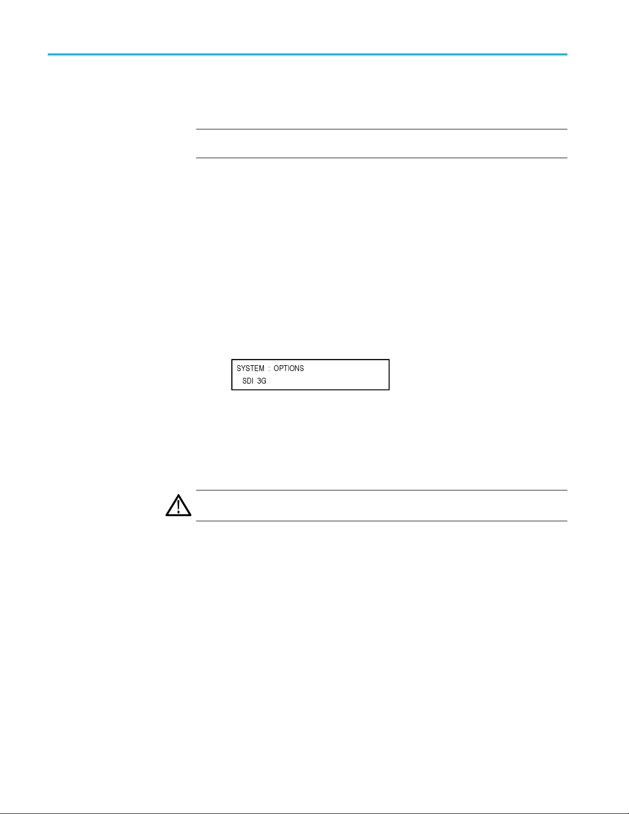
How to upgrade the instrument firmware
5. After the firmwa
into the directory of your choice: transfer.exe and firmware.pkg.
NOTE. If a readme.txt file is included in the firmware package, be sure to read the
file before you upgrade the firmware.
6. If the firmware in your instrument must be upgraded, verify which options
are currently installed before you install the software. After you install the
upgrade, you will verify that any previously installed options are still enabled.
a. Connect the instrument and computer to your local Ethernet network. See
the SPG8000A Installation and Safety Instructions for information about
installing the instrument on a network.
b. Press the SYSTEM button to access the SYSTEM menu.
c. Press the up (▲)ordown(▼) arrow button to select SYSTEM :
OPTIONS. The second line of the display lists the options, if any, that are
installed in the instrument. None is displayed if no options are installed,
and SDI
re package ZIP file is downloaded, extract the following files
3G is displayed if Option SDI is installed.
d. Make a note of the installed options.
7. If the firmware in your instrument must be upgraded, to prevent the loss of
your user files, be sure to backup your user files to a USB drive. (See page 23,
To transfer user files from an instrument to a USB drive.) You will restore
the user files at the end of the upgrade procedure.
CAUTION. To prevent the loss of your user files, be su re to use the Backup All
er Data to USB option in the backup procedure.
Us
28 SPG8000A User Manual

Firmware upgrade overview
There are two methods for upgrading the instrument firmware:
UsingaUSBmemorydevice(Seepage29,USB firmware upgrade.)
How to upgrade the instrument firmware
UsinganEthe
firmware upgrade.)
The time req
CAUTION. The instrument automatically reboots at the end of the upgrade process.
Do not perform the upgrade while the instrument is in use as a sync reference.
Once the instrument h as started to erase internal flash, do not remove power
from the instrument. If you do so, the instrument flash may be corrupted and
you will have to run the recovery procedure. (See page 34, Firmware upgrade
trouble
NOTE. If power to the instrument is lost before it begins erasing the internal flash,
you can
displays only a blank screen after power is reapplied, see the troubleshooting
section for help. (See page 34, Firmware upgrade troubleshooting.)
If you have loaded the instrument memory with a large number of test signals
or frame picture files, you may not be able to upgrade the instrument firmware
because the memory is too full. If you receive a memory error while attempting to
upgrade the firmware, you need to delete some of the test signal or frame picture
files and then perform the upgrade.
shooting.)
restart the firmware upgrade after the instrument reboots. If the instrument
rnet network (requires a Windows PC) (See page 32, Network
uired to complete the firmware upgrade is approximately 10 minutes.
USB firmware upgrade
Use the following steps to upgrade the instrument firmware using a USB memory
device.
1. Insert a USB memory device into a USB port of the computer containing the
latest instrument firmware.
2. On the computer, navigate to the USB device.
3. On the USB device, create a directory named SpgUpgrd.
CAUTION. To prevent upgrade failure, be sure to correctly name the upgrade
directory. The directory name is case sensitive, with the “S” and the “U” in
SpgUpgrd being upper case.
SPG8000A User Manual 29
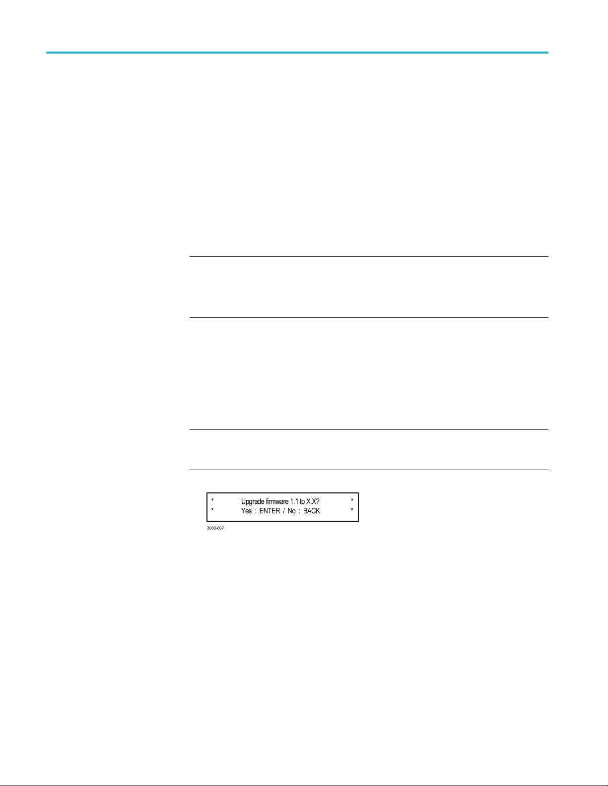
How to upgrade the instrument firmware
4. Open the SpgUpg
downloaded ZIP file to the USB device. The USB device should have a
directorypathofSpgUpgrd\firmware.pkg.
5. Eject and safely remove the U SB device from the computer.
6. If necessar
start up before inserting the USB device into the front-panel USB port on the
instrument.
7. Press the SYSTEM button to access the SYSTEM menu.
8. Verify tha
down (▼) arrow button to select SYSTEM : USB (Mounted).
NOTE. The display will read “Mounted” if the USB device is properly installed. If
the display reads “Unmounted”, try to reinstall the USB device.
If the instrument still does not recognize the USB device, attempt this procedure
again using a different USB device from a well known brand that is 16 GB or less.
9. Press the up (▲)ordown(▼) arrow button to select SYSTEM :
FIRMWARE UPGRADE.
y, power on the instrument and wait for the instrument to fully
t the USB device is properly installed by pressing the up (▲)or
rd directory and copy the firmware.pkg file from the
10. Press the left (◄) or right (►) arrow button to select USB Upgrade,andthen
press the ENTER button. A confirmation message is displayed as shown
below.
NOTE. If the instrument displays the message ERROR: SpgUpgrd/firmware.pkg
found, make sure you have the correct directory path on the USB device and
not
then restart this procedure at step 6.
30 SPG8000A User Manual

How to upgrade the instrument firmware
11. A second confirm
upgrade will delete all user-created files on the instrument.
CAUTION. If you did not backup your user files as part of the upgrade preparation
process, it is recommended that you press the BACK button to cancel the upgrade
and then backup your user files before performing the upgrade. (See page 23, To
transfer user files from an instrument to a USB drive.) You will restore the user
files at the e
12. Press the ENTER button to proceed with the upgrade or press the BACK
button to cancel the upgrade.
13. When you press ENTER, the upgrade process begins. During the upgrade
process, the instrument displays messages indicating the upgrade status.
CAUTION. Once the instrument has started to erase internal flash, do not remove
power from the instrument. If you do so, the instrument flash may be corrupted
and you will have to run the recovery procedure. (See page 34, Firmware upgrade
leshooting.)
troub
nd of the upgrade procedure.
ation is displayed as shown below to remind you that the
14. If the instrument does not reboot at the completion of the firmware upgrade,
ove and then reconnect the power cable(s).
rem
15. Remove the USB device after the upgrade is complete:
UTION. To prevent a loss of data on the USB device, use the SYSTEM menu to
CA
unmount the USB device before removing it from the instrument.
ress the SYSTEM button.
a.P
b. Press the up (▲)ordown(▼) arrow button to select SYSTEM : USB
(Mounted), and then press the ENTER button.
c. Remove the USB device from the instrument when the message Yo u m a y
now safely remove the USB drive appears.
16. Proceed to Verify the firmware upgrade and reinstall user files. (Seepage34.)
SPG8000A User Manual 31

How to upgrade the instrument firmware
Network firmwa
re upgrade
Use the following steps to upgrade the instrument firmware using a network
connection:
1. Connect the instrument and a Windows PC to your local Ethernet network
2. Prepare th
or directly connect the instrument to a Windows PC. See the SPG8000A
Installati
instrument on a network.
a. Press the SYSTEM front panel button.
b. Press the up (▲)ordown(▼) arrow button to select SYSTEM :
c. Press the left (◄)orright(►)arrowbuttontoselectNetwork Upgrade,
d. A second confirmation is displayed as shown below to remind you that the
on and Safety Instructions for information about installing the
e instrument for the firmware upgrade:
FIRMWARE UPGRADE.
andthenpresstheENTER button. A confirmation message is displayed
as show
upgrade will delete all user-created files on the instrument.
nbelow.
CAUTION. If you did not backup your user files as part of the upgrade
preparation process, it is recommended that you press the BACK button to
cel the upgrade and then backup your u ser files before performing the
can
upgrade. The instructions for backing up user files is described in the section
To transfer user files from an instrument to a USB drive. (See page 23.) You
will restore the user files at the end of the upgrade procedure.
e. Press the ENTER button to proceed with the upgrade or press the BACK
button to cancel the upgrade.
f. When you press ENTER, a Waiting for network connection message is
displayed along with the IP address of the instrument. This indicates the
instrument is ready to be upgraded. An example display is shown below.
32 SPG8000A User Manual

How to upgrade the instrument firmware
3. Perform the firm
a. On the PC, double-click the transfer.exe file to launch the transfer
program.
b. Type the IP address or DNS name of the instrument you are upgrading,
and then pre
indicating the progress of the upgrade appear in the transfer program
window and on the instrument display.
CAUTION. Once the instrument has started to erase internal flash, do not
remove power from the instrument. If you do so, the instrument flash may be
corrupted and you will have to run the recovery procedure. (See page 34,
Firmware
NOTE. The upgrade will not proceed until all of the firmware data is
transfe
will attempt to complete the upgrade even if it loses contact with transfer.exe.
So that you can monitor the progress of the upgrade, it is suggested that you
do not close the transfer.exe window until the transfer utility asks for another
IP address.
rred to the instrument. Once the upgrade has started, the instrument
ware upgrade:
ss Enter.Thisstartsthefirmware upgrade process. Messages
upgrade troubleshooting.)
Figure 6: Sample o f transfer.exe window after the upgrade is complete
4. If the instrument does not reboot at the completion of the firmware upgrade,
remove and then reconnect the power cable.
5. Proceed to Verify the firmware upgrade and reinstall user files. (Seepage34.)
SPG8000A User Manual 33

How to upgrade the instrument firmware
Verify the firm
ware upgrade and reinstall user files
1. After the instrument reboots at the end of the upgrade process, press the
SYSTEM button to access the SYSTEM menu.
2. Press the up (▲)ordown(▼)arrowbuttontoselectSYSTEM : OPTIONS.
The second line of the display lists the options, if any, that are installed in
the instrum
displayed if Option SDI is installed.
3. Verify that the options listed match those that you noted before the upgrade.
4. Press the up ( ▲) or down (▼)arrowbuttontoselectSYSTEM : VERSION
INFO (F/W). The second line of the display lists the installed firmware
version.
5. Verify that the displayed firmware version is the same version as the firmware
package you used to perform the upgrade.
6. Ifyoubackedupyouruserfiles before you upgraded the firmware, reinstall
your user files as described in the section To install user files from a USB
drive to an instrument.(Seepage24.)
ent. None is displayed if no options are installed, and SDI 3G is
ION. To prevent the loss of your user files, be sure to use the Restore All
CAUT
User Data from USB option in the restore procedure.
Firmware upgrade troubleshooting
If a power failure occurs during the upgrade and the instrument has a blank screen
when you reapply power, perform the following procedure.
1. Connect an Ethernet cable between the instrument and your computer or
local Ethernet network.
2. Remove the power cable to turn off the instrument.
3. Press and hold the STATUS button and then reconnect the power cable.
Continue to hold the STATUS button until the message Select upgrade
network speed: appears on the top line of the LCD display.
4. Press the left (◄)orright(►) arrow button to select a network speed
(10BaseT, 100BaseT, or 1000BaseT), and then press the ENTER button.
If you do not know your network speed, the 100BaseT selection is
recommended.
34 SPG8000A User Manual

How to upgrade the instrument firmware
5. When the messag
left (◄)orright(►) arrow button to select from the following modes and
then press the ENTER button.
DHCP – Use this selection if the instrument is connected to a network
with DHCP support. An IP address will be assigned to the instrument
from your network server.
Local IP (192.168.1.1) – Use this selection if the instrument is connected
to a network without DHCP support or is connected to a standalone
computer, and you want to use the factory default, static IP address of
192.168.1.1 for the upgrade.
NOTE. Whe
mode, you cannot edit the displayed IP address. The IP address cannot be
edited when the instrument is in recovery mode.
Saved static IP (IP address) – Use this selection if the instrument is
connected to a network without DHCP support or is connected to a
standalone computer, and you want to use the previously saved static IP
address assigned to the instrument for the upgrade. The sa ve d IP address
is displayed.
e Select upgrade network mode: is displayed, press the
n you select either the Local IP or the Saved static IP upgrade
Quit and continue booting – Use this selection to quit the upgrade
process and leave the instrument in its current condition.
6. If you did not select Quit and continue booting in the previous step, the top
line of the instrument display will show the message Waiting for network
nection and the second line will list an IP address. Make a note of the
con
displayed IP address.
7. En
CAUTION. To prevent upgrade failure, leave the instrument power on during the
upgrade process. The upgrade process may take up to 15 minutes to complete.
8. When the upgrade is complete, the instrument should reboot. If it does not,
If you continue to experience an upgrade problem, contact Tektronix customer
support or your local Tektronix representative for assistance.
ter the IP address you noted in the previous step into the upgrade transfer
application window on your PC to restart the upgrade process.
cycle the power.
SPG8000A User Manual 35

How to operate an instrument with two power supplies (Option DPW only)
How to operate an instrument with two power supplies
(Option DPW only)
The standard instrument has one Power Supply module installed. With Option
DPW, a second hot-swappable, redundant (backup) Power Supply module is
provided. When two Power Supply modules are installed in the instrument, one is
configured as the primary supply and the other is configured as the backup supply.
In the event that the primary supply fails, the backup supply automatically
provides power to maintain instrument operation. You can remove and replace
a failed s
page 39, To hot-swap a Power Supply module.)
Power supply status
The status of the Power Supply modules can be viewed from the front or rear of
the instrument. On the front panel, the PWR1 and PWR2 indicators illuminate
using various colors to show the status of the Power Supply modules. The rear
panel of each Power Supply module has a STATUS LED that matches the status
shownonthePWR1andPWR2indicators. SeetheSPG8000A Installation and
Safet
upplywithouthavingtoremovetheinstrument from operation. (See
y Instructions for information about the power supply status indicators.
Temperature weighted
hours (TWH)
You can use the SYSTEM menu to perform a load test on the backup supply and
ew voltage levels in the instrument.
to vi
The instrument keeps track of the age of a Power Supply module by calculating
the temperature weighted hours (TWH). You can view the TWH of each installed
pply using the SYSTEM : DIAGNOSTICS menu.
su
TWH calculation method. When the outside air temperature is at 25 °C or
cooler, the Power Supply module is expected to last 15 years. As the outside air
temperature rises to the maximum operating temperature of 50 °C, the expected
life of the supply decreases to 5 years. Every hour, the instrument measures the
outside temperature and increments the temperature weighted hours count in
response to the measured tempera ture.
When the TWH value reaches a value of 131,400, then the associated PWR1 or
PWR2 indicator will be set to orange to indicate that the supply should be replaced.
NOTE. When two Power Supply modules are installed, the active supply runs
warmer than the backup supply. Therefore, the TWH of the active supply will
increase faster than the backup supply.
36 SPG8000A User Manual

How to operate an instrument with two power supplies (Option DPW only)
To configure th
e preferred (active) supply
Perform the following steps to configure which Power Supply module is the
preferred (active) supply:
NOTE. The pr
modules are installed and both of the supplies are connected to a power source.
If there are two Power Supply modules installed but one of the supplies has a
failure, the good supply will be used to power the instrument regardless of the
preferred supply configuration.
The recommended usage strategy is to configure one supply as preferred, and use
the second supply only in case the first supply has a failure. This usage strategy
allows the backup supply to have the maximum remaining life when it is needed.
The preferred supply configuration is not saved as part of t he preset system.
Therefore, the preferred supply configuration will not change when you activate
any of the system presets, including the Factory Default preset. (See page 143,
Presets submenu.)
The following procedure uses the front panel controls on the instrument to
configure the preferred (active) supply. You can also use the System > General
Settings submenu in SPG8000A Web Interface to configure the preferred supply.
(See page 144, General Settings s
eferred supply configuration only applies if two Power Supply
ubmenu.)
1. Check the status of the front-panel PWR1 and PWR2 indicators:
Bright green indicates the preferred (active) supply.
Dim green indicates the inactive (backup) supply.
NOTE. If the color of the PWR1 or PWR2 indicators is other than bright or
dim green, service the faulty Power Supply module before proceeding.
2. Check the temperature weighted hours of the installed supplies:
NOTE. It is recommended that you configure the supply with the most temperature
weighted hours to be used as the primary preferred supply. This allows for the
newer supply to be preserved so it can provide the best possible backup should the
primary supply fail. (See page 36, Temp
a. Press the SYSTEM button to access the S YSTEM menu.
b. Press the up (▲)ordown(▼) arrow button to select SYSTEM :
DIAGNOSTICS, and then press the ENTER buttontoaccessthe
DIAGNOSTICS menu.
erature weighted hours (TWH).)
SPG8000A User Manual 37

How to operate an instrument with two power supplies (Option DPW only)
c. Press the up (▲)
DIAGNOSTICS : POWER SUPPLY 1. The second line of the display
will list the number of hours the supply has been the active supply and the
backup supply.
d. Press the right (►) arrow button to display the number of temperature
weighted hours of the first supply as shown below. Note the number of
hours of hours shown.
e. Press the up (▲)ordown(▼) arrow button to select SYSTEM :
DIAGNOSTICS : POWER SUPPLY 2.
f. Press the right (►) arrow button to display the number temperature
weighted hours of the second supply. Note the number of hours of hours
shown.
3. If the Power Supply module with the greatest number of temperature weighted
hours i
Otherwise, you do not need to change the preferred supply configuration.
4. To cha
access the SYSTEM menu.
s not the currently the preferred supply, then continue this procedure.
nge the preferred supply configuration, press the SYSTEM button to
or down (▼) arrow button to select SYSTEM :
5. Pres
6. Pre
NOTE. When viewed from the front of the instrument, Power Supply 1 is the left
Power Supply module and Power Supply 2 is the right Power Supply module. This
m
7. If status of the supply is Inactive, press the ENTER button to change the
stheup(▲)ordown(▼)arrowbuttontoselectSYSTEM : POWER
SUPPLY PREFERRED SELECT.
ss the left (◄)orright(►) arrow button to display the supply you want
to be the primary (active) supply: Power Supply 1 or Power Supply 2. The
second line of the display shows the supply status: Active, Preferred or
Inactive.
atches the orientation of the PWR1 and PWR2 indicators on the front panel.
status to Active, Preferred. The front-panel indicator for the selected supply
should change to bright green.
38 SPG8000A User Manual

How to operate an instrument with two power supplies (Option DPW only)
To hot-swap a P
ower Supply module
This procedure describes how to replace a Power Supply module while the
instrument is in operation. Perform the following steps to hot-swap a Power
Supply modul
WAR NI NG . Disconnect the power cord from the Power Supply module before you
remove the module from the instrument. Also, do not connect a power cord to the
Power Supply module while the module is not installed in the instrument. There
are dangerous high voltages inside the module when the power cord is connected.
CAUTION. To prevent an unexpected shutdown of the instrument, be sure to
unplug the correct power cord if you are replacing a faulty Power Supply module.
(See Figure 7.)
When viewed from the front of the instrument, Power Supply 1 is the left Power
Supply module and Power Supply 2 is the right Power Supply module. This
matche
The STATUS LED on the rear panel of each Power Supply module will match the
status shown by the front-panel PWR1 and PWR 2 indicators.
1. Remove the power cable from the Power Supply module that you are
s the orientation of the PWR1 and PWR2 indicators on the front panel.
removing or replacing.
e:
2. Pull out the handle located at the bottom of the supply. (See Figure 7.)
3. Whi
4. In
5. If necessary, push the handle of the supply into the storage position.
6. Connect the power cable to the Power Supply module you installed.
7. Check that the status of the Power Supply module you just installed is bright
8. If desired, change the preferred supply configuration. (See page 37, To
NOTE. It is recommended that you configure the supply with the most temperature
weighted hours to be used as the primary preferred supply. This allows for the
newer supply to be preserved so it can provide the best possible backup should
the primary supply fail.
le pushing the retaining latch to the left, use the handle to pull the Power
Supply module out of the instrument.
sert the replacement supply into the instrument until it latches into place.
or dim green.
configure the preferred (active) supply.)
SPG8000A User Manual 39

How to operate an instrument with two power supplies (Option DPW only)
Figure 7: Removing a Power Supply module
40 SPG8000A User Manual

How to use Stay Genlock
®
How to use Stay
About Stay Genlock
To enable Stay Genlock
®
Genlock
Stay GenLoc
additional robustness and stability for genlocked Sync Pulse Generators (SPGs),
as in a master/slave configuration.
If the external reference is removed from the genlock input, the instrument
must use the internal oscillator as a frequency reference. Although the OXCO
is a precision component, small frequency differences are inevitable. However,
the Stay GenLock
therefore attempts to hold the last stable frequency before genlock was lost.
See the Video Sync Pulse Generator and Electronic Changeover Unit System
Integration Technical Reference manual for more information about the Stay
®
Genloc
To ena
steps:
k
®
ble the Stay GenLock
®
®
k
is a digital genlock technology developed by Tektronix to provide
®
technology maintains a history of the clock frequency, and
function.
®
function on the instrument, perform the following
NOTE. The following procedures use the front panel controls on the instrument to
®
enableStayGenLock
Interface to enable Stay GenLock
1. Press the front-panel REFERENCE button to access the REFERENCE menu.
2. Use the up (▲)ordown(▼) arrow button to display REFERENCE : LOCK
LOSS ACTION.
3. Use the left (◄)orright(►) arrow button to display Stay at Current
Frequency, and then press the ENTER button to confirm the selection.
. You can also use the Reference menu in SPG8000A Web
®
.(Seepage79,Referencemenu.)
SPG8000A User Manual 41

How to use Stay Genlock
®
42 SPG8000A User Manual

AES menu
Use the AES button menu to view and configure the timing offset of the Word
Clock (48 kHz) and DARS outputs and to set the signal level of the Word Clock.
When Option AG is installed, use this menu to configure the AES audio
output settings such as the frequency, amplitude, resolution, timing offset, and
audio/vide
The following figure shows the AES menu including the Global Settings and
Channel Pa
o synchronization.
rameters.
Figure 8: AES menu
SPG8000A User Manual 43

AES menu
Global Settin
Audio-Video Sync
gs
Resolution
This menu item is available only when Option AG is installed. Sets the resolution
of the serial digital audio signal data. Use the drop down menu to select 20 bits or
24 bits.
This menu item is available only when Option AG is installed. This menu item
selects the frame reset signal that is synchronized with the Word Clock and
DARS signa
Use the drop-down list to select the frame reset signal:
Free Run. The Word Clock and DARS signals are not synchronized with
any of the frame reset signals.
Frame Reset 1 (2.997 Hz)
Frame Reset 2 (6.250 Hz)
Frame Reset 3 (3.000 Hz)
NOTE. If the frame reset signal used by the Word Clock and DARS signals is
reset by a change of the video format, the Word Clock and DARS signal timing
is also reset.
l outputs.
Delay
AES Word Clock Outp ut
Use this to set the timing offset of the Word Clock and DARS outputs relative
to the genlock signal or the internal reference signal.
ts the signal level of the Word Clock output. Use the drop-down list to select
Se
1Volt(AC)or 5Volt(DC).
44 SPG8000A User Manual

AES menu
Channel Param
Frequency
Amplitu
Audio click
eters
de
This menu is available only when Option AG is installed. Select the parameters
for audio Channel 1 to Channel 8 from the following drop-down lists.
Sets the audio signal frequency for the selected audio channel. The choices are:
Inactive
Silence
50 Hz
100 Hz
150 Hz
200 Hz
250 Hz
300 Hz
When Inac
400 Hz
500 Hz
600 Hz
750 Hz
800 Hz
1000 Hz
1200 Hz
1500 Hz
1600 Hz
2000 Hz
2400 Hz
3000 Hz
3200 Hz
4000 Hz
4800 Hz
5000 Hz
tive is selected, audio data output is disabled.
6000 Hz
8000 Hz
9600 Hz
10000 Hz
12000 Hz
15000 Hz
16000 Hz
20000 Hz
Sets the audio signal amplitude for the selected audio channel. Set the value from
-60 dBFS to 0 dBFS.
Inserts audio clicks in the selected audio channel. The audio tone, if any, is turned
off for an interval around the audio click. The choices in the drop-down list are
None, 1 Second, 2Second, 3Second,and4 Second.
Audio Click becomes valid when you select 1Secondto 4 Second for the Audio
Click rate. When Audio Click is valid, Audio Tone is turned off for 0.25 seconds
around the click. For example, if you select 3Secondfor the click rate, the audio
e will be output for 2.75 seconds, and silent for 0.25 seconds; the click occurs
ton
during this silence. When Audio Click is None, the Audio Tone selected with the
Frequency setting is output continuously. Audio Click makes it easy to identify
any of the four output channels.
SPG8000A User Manual 45

AES menu
AES menu facto
ry default settings
The following table shows the settings for the AES button menu that are reset
when you use the PRESET submenu to recall the factory default settings. (See
page 143, Preset
Table 4: AES Global Settings factory default settings
Menu item name Settings
Resolution 20 bits
Audio-Video S ync
Delay 0.0 μsec
AES Word Clock Output 1 Volt (AC)
Table 5: AES Channel Parameters factory default settings
Menu item name Frequency Amplitude Audio Click
Ch. 1 to Ch. 8
s submenu.)
Free Run
1000 Hz -20.0 dB None
46 SPG8000A User Manual

Black menu
UsetheBlackmenutoviewandconfigure the Black outputs. Click one of the
bars for the five Black outputs (1, 2, 3, 4, or 5) to open the configuration submenu
for that output. Black outputs 1–3 are standard; Black outputs 4–5 are available
only with Option BG. The bars for each Black output lists the current signal being
output (i.e
The following figure shows the Black menu with the Black 2 submenu expanded.
Most of the entries in all five submenus are the same with the differences noted
below.
. NTSC Black Burst).
Figure 9: Black menu with the B lack 2 submenu expanded
NOTE. Black outputs 1–3 are a group that must use the same HD tri-level sync
rate. Likewise, Black outputs 4–5 are a group that must use the same HD tri-level
sync rate. Both groups can output the same rate or they can output different rates.
When the instrument is in Factory mode, a Calibration menu option is available.
See the SPG8000A Service Manual for more information.
SPG8000A User Manual 47

Black menu
Black Output s
ettings
Format
This submenu contains the Format and Field Reference selections.
Use drop-down list to select the signal format for the selected Black output.
Not all of the formats are available for the Black outputs; the available format
choices depend on the following:
The CW 10 M Hz format appears only for the Black 3 output. When CW
10 MHz is the selected output format, other Black menu items are unavailable
for the Black 3 output.
The available HD output formats depend on whether the HD tri-level sync rate
for the selected Black output is set to integer or non-integer. (See Table 6.)
Table 6: Black output formats
teger formats
Non-in
NTSC NTSC
PAL PAL
NTSC-J NTSC-J
CW 10 MHz
1080 59.94i 1080 60i
1080
1080 29.97p 1080 24sF
1080 23.98p 1080 30p
0 59.94p
108
1080 47.95p 1080 24p
720 59.94p 1080 60p
1 PPS
1
The CW 10 MHz format selection appears only for the Black 3 output.
1
23.98sF
rformats
Intege
CW 10 MHz
50i
1080
0 25p
108
80 50p
10
080 48p
1
720 60p
720 50p
1 PPS
1
Field Reference
This menu item is available only for non-HD formats. Use the drop-down list to
select Enable or Disable for the field reference on the selected Black output.
48 SPG8000A User Manual

Black Timing settings
Black menu
Use these settings to adjust the timing offset of the selected Black output relative
to the internal reference signal. The range of the timing adjustment d epends on
the format of the selected Black output.
Vertical Delay
Horizontal Delay
Enter the Vertical Delay in 1 line increments for the selected Black output.
Enter the Horizontal Delay in increments based on the format of the selected
Black output.
NOTE. If you are using the 50, 59.94 or 60 Hz progressive sync as a genlock
source, as well as LTC as a time-code source, there are two possible alignments
for the resulting system. Alignment can be checked by looking at the LTC timing
status screen. If the timing is near zero, then it is aligned. If the timing is near a
frame of offset, then it is not aligned.
You must unlock and re-lock the reference to achieve the desired alignment if this
is important to the application y ou are using. Alternatively, you can use a lower
frame rate video reference like NTSC, PAL, or 1080i tri-level.
The following table shows the Vertical Delay line settings and Horizontal Delay
adjustment ranges.
Table 7: Black output timing adjustment ranges
Format nam e Line settings Coarse settings (μs) Fine settings (ns)
NTSC
PAL ± 1250 ± 64.0000 ± 10.00
1080 60i ± 562 ± 29.6296 ± 10.00
1080 59.94i ± 562 ± 29.6593 ± 10.00
1080 50i ± 562 ± 35.5556 ± 10.00
1080 24sF ± 562 ± 37.0370 ± 10.00
1080 23.98sF ± 562 ± 37.0741 ± 10.00
1080 30p ± 562 ± 29.6296 ± 10.00
1080 29.97p ± 562 ± 29.6593 ± 10.00
1080 25p ± 562 ± 35.5556 ± 10.00
1080 24p ± 562 ± 37.0370 ± 10.00
1080 23.98p ± 562 ± 37.0741 ± 10.00
720 60p ± 375 ± 22.2222 ± 10.00
720 59.94p ± 375 ± 22.2444 ± 10.00
720 50p ± 375 ± 26.6667 ± 10.00
± 525 ± 63.5556 ± 10.00
SPG8000A User Manual 49

Black menu
Black Timecode settings
NOTE. The Black Timecode settings are available only when a non-HD format is
set as the sign
al format of the selected Black output.
Source
Offse
Use the drop-down list to select the timecode source. The default value is Disable.
Disable: Disables the timecode function for the selected Black output.
Local (DST): Uses the local time of day with Daylight Savings Time offset
as the timecode.
Local (No DST): Uses the local time of day without Daylight Savings Time
offset as the timecode.
UTC: Uses Coordinated Universal Time as the timecode.
Program Time: Uses the program time counter as the timecode.
NOTE. In addition to enabling the timecode source, at least one line must be
specified and enabled to carry a VITC signal.
Enter an offset for the selected Black output, relative to the selected timecode
t
source in the format ±HH:MM:SS:FF. You can enter a time offset of up to
±23:59:59:29 (maximum frame value depends on the frame rate of the video
al).
sign
NOTE. The Offset adjustment allows you to enter a time zone correction of up to
±23:59 hours. However, the ST309 standard only implements codes for time zones
in the range of -12 to +13 hours. Therefore, when you are using ST309 data as the
Time of Day source, it is recommended that the combined programmed offset from
time zone and daylight savings time be restricted to the range of -12 to +13 hours.
VITC 1 and 2 Line
selections
50 SPG8000A User Manual
Use these menu items to insert the same VITC signal on 1 or 2 lines of the vertical
interval.
Enter the video line number to insert the selected VITC signal. For NTSC, you
canselectlinesfromline10to20(lines14and16arerecommended). ForPAL,
you can select lines between 6 and 22 (lines 19 and 21 are recommended).
Select the Enable check box for the selected line to enable or disable the output
of a VITC signal.

Black menu
Enable 30 Drop-Frame
Use the check bo
applications will prefer drop-frame compensation VITC on NTSC, but if needed,
it can be disabled by this menu item. This menu item appears only when NTSC or
NTSC-J is set as the signal format for the selected Black output.
Blank On Reference Unlock settings
These settings are available only for the Black 2 output. Use the Enable check
box to enable or disable the blanking function when a loss of lock to the reference
signal is detected. When enabled, the Black 2 output will be blanked for as long
of lock condition occurs. The purpose of this function is to trigger a
k 2 output is blanked. Enter the delay in HH:MM:SS.
Delay
as the loss
downstream change-over unit.
NOTE. When the Black 2 output is configured to blank on the loss of reference
lock, the output should not be used for normal reference applications.
When the Blank on Reference Unlock function is enabled, you can set the amount
of time delay before the Black 2 output will be blanked when a loss of lock to the
reference signal is detected. The purpose of the delay is to reduce false alarms by
allowing a set amount of time for the loss of lock condition to clear before the
Blac
xtoenableordisablethe30DropFramemode. Most
HD Tri-level Sync Rate
this setting to set the HD tri-level sync rate for the 5 Black outputs. The HD
Use
tri-level sync rate setting limits which signal formats are available for the Black
outputs. Select the desired group of Black outputs (1–3 or 4–5) for which to
set the HD tri-level sync rate.
Use the drop-down list to select either Non-Integer (59.94, 47.95, 29.97, 23.98)
orInteger (60, 50, 48, 30, 25, 24).
NOTE. The Black outputs 1–3 are a group that must use the same HD tri-level
sync rate (integer or non-integer). Likewise, the BLACK outputs 4–5 (Option BG
only) are a group that must use the same HD tri-level sync rate. Both groups can
output the same rate or they can output d ifferent rates.
The HD tri-level sync rate setting limits which signal formats are available for
the selected group of Black outputs.
SPG8000A User Manual 51

Black menu
Black menu fac
tory default settings
The following table shows the settings for the Black menu that are reset when
you use the Preset submenu to recall the factory default settings. (See page 143,
Presets subm
Table 8: Black menu factory default settings
Menu item name Settings
Black 1 to Black 5
enu.)
1
Format
Field Reference
Timing
Timecode
Blank On Reference Unlock
4
NTSC
2
Disable
Vertical: 0 Line(s)
Horizontal Coarse: 0.0 μsec
2
Source: Disable
Offset: +00:00:00:00
VITC 1 Line
Line Number:
NTSC/NTSC-J: 14
PAL: 19
Output: Disable
VITC 2 Line
Line Number:
NTSC/NTSC-J: 16
PAL: 21
Output: Disable
Enable 30 Drop Frame: Enabled
3
Disabled
Blank On Reference Unlock
4
Delay
Black 1–3: HD Tri-Level Sync
Black 4–5: HD Tri-Level Sync
1
Black outputs 4–5 are available only when Option BG is installed.
2
These settings appear only for non-HD formats.
3
his setting appears only when the format is set to NTSC.
T
4
These settings appear only for the Black 2 output.
1
00:00:10
Non-integer
Non-integer
52 SPG8000A User Manual

Composite menu (Option BG only)
When Option BG is installed, use the Composite menu to view and configure the
composite video outputs. The following figure s hows the Composite menu with
the Composit
e 1 submenu expanded.
ure 10: Composite menu
Fig
SPG8000A User Manual 53

Composite menu (Option BG only)
Composite out
Test Signal
put settings
Format
Use the drop-down list to select the desired signal formats in the following table.
NOTE. When you change the signal format, synchronization shock will occur.
Use the drop-down list to select the desired test signal. The available signals
depend on the selected format (NTSC/NTSC-J or PAL).
Table 9: C
NTSC or NTSC-J format PAL format
Black Bur
Black Burst with field reference
Black Burst with 10-field ID 100% Color Bars
100% Color Bars 75% Color Bars
75% Color Bars 100% Color Bar Over Red
SMPTE EG1 Color Bar 75% Color Bar Over Red
40% Flat Field 40% Flat Field
Convergence Convergence
Pluge and Luma Reference Pluge and Luma Reference
Shallow Ramp CCIR 17
NTC7 Combination CCIR 18
NTC7 Composite
omposite output test signals
st
Black Burst without field reference
Black Bu
rst
54 SPG8000A User Manual

Composite menu (Option BG only)
Composite Tim
Horizontal
ing settings
The following settings allow you to set the timing offset for the selected
Composite signal output.
Use this submenu to adjust the timing offset of the selected Composite output
relative to the genlock signal or the internal reference signal.
NOTE. The h
Vertical
Use this menu item to enter the vertical timing by ± ½ a color frame. (See
Table 10.
Use this menu item to enter the horizontal offset. You can enter the value from -1
lineto+1lineinoneclocksteps(18.5ns).
Table 1
Format name Vertical line settings Horizontal time settings (μs)
NTSC/NTSC-J
PAL ± 1250 ± 64.0
orizontal timing can be adjusted only in clock cycle increments.
)
0: Timing adjustment ranges for composite output signals
± 525 ± 63.5
556
000
Composite Timecode settings
The following settings allow you to set timecode parameters for the selected
Composite output.
Use this submenu to set timecode parameters for the selected output.
e the drop-down list to select the timecode source from the following choices.
Source
Us
The default value is Disable.
isable: Disables the timecode function for the composite outputs.
D
Local (DST): Uses the local time of d ay with Daylight Savings Time offset
as the timecode.
Local (No DST): Uses the local time of day without Daylight Savings Time
offset as the timecode.
UTC: Uses Coordinated Universal Time as the timecode.
Program Time: Uses the program time counter as the timecode.
SPG8000A User Manual 55

Composite menu (Option BG only)
Offset
VITC 1 and 2 Line
selections
Usethismenuit
timecode input. You can enter a time offset of up to ±23:59:59:29 (maximum
frame value depends on the frame rate of the video signal) of the selected time of
day source in the Time menu (hours : minutes : seconds : video frames).
NOTE. The Offset adjustment allows you to enter a time zone correction of up to
±23:59 hours. However, the ST309 standard only implements codes for time zones
in the range
the Time of Day source, it is recommended that the combined programmed offset
from time zone and DST be restricted to the range of -12 to +13 hours.
Use these menu items to insert the same VITC signal on 1 or 2 lines of the vertical
interval.
Enter the video line number to insert the selected VITC signal. For NTSC, you
canselectlinesfromline10to20(lines14and16arerecommended). ForPAL,
you can select lines between 6 and 22 (lines 19 and 21 are recommended).
Select the Enable check box for the selected line to enable or disable the output
of a VI
TC signal.
em to set a time offset for the composite outputs from the
of -12 to +13 hours. Therefore, when you are using ST309 data as
Enable 30 Drop-Frame
Use the check box to enable or disable the 30 Drop Frame mode. Most
applications will prefer drop-frame compensation VITC on NTSC, but if needed,
an be disabled by this menu item. This menu item appears only when NTSC or
it c
NTSC-J is set as the signal format for the selected Composite output.
56 SPG8000A User Manual

Composite menu (Option BG only)
Composite men
u factory default settings
The following table shows the settings for the Composite menu that are reset
when you use the Preset submenu to recall the factory default settings. (See
page 143, Preset
Table 11: Composite menu factory default settings
Menu item name Settings
Composite 1 or Composite 2
Format
Test Signal NTSC/NTSC-J: Black Burst
TIMING Vertical: 0 .0 Line(s)
TIMECODE SOURCE: Disable
1
s menu item appears only when the format is set to NTSC or NTSC-J.
Thi
s submenu.)
NTSC
PAL: Black Burst No Field Reference
Horizontal: 0.0 μsec
OFFSET: +00:00:00:00
30 DROP FRAME: Enable
VITC 1 Line
Line Number:
NTSC/NTSC-J: 14
PAL: 19
Output: Disable
VITC 2 Line
Line Number:
NTSC/NTSC-J: 16
PAL: 21
Output: Disable
Enable 30 Drop Frame: Enabled
1
3
SPG8000A User Manual 57

Composite menu (Option BG only)
58 SPG8000A User Manual

Dolby-E Configuration menu (Option DBT only)
When Option DBT is installed, use the Dolby-E Configuration menu to view
and configure settings for Dolby-E channel 1 (CH1) or channel 2 (CH2). The
following fig
expanded.
ure shows the Dolby-E menu with the DOLBY-E-CH1 submenu
Figure 11: Dolby-E Configuration menu
SPG8000A User Manual 59

Dolby-E Configuration menu (Option DBT only)
Dolby-E Chann
Program Type
Signal Level
Bit Depth
Start Position
el Configuration
Use this m enu item to specify the program configuration of the Dolby-E signal.
This parameter controls both the number of programs in the stream as well as how
the eight aud
Use the drop down list to select 5.1, 5.1+2 (default value), 7.1, 4x2,or8x1.
Use this menu item to set the level of the Dolby-E signal. Use the drop down list
to select –18.0 dBFS, –20.0 dBFS,orMulti Tone.
Use this menu item to set the bit depth of the Dolby-E signal when the program
type is set to 5.1. Use the drop down list to select 16 bits or 20 bits.Thebitdepth
setting is forced to 20 bits for all Dolby E program types except 5.1.
If you set the Dolby-E bit depth to 16 bits, the Dolby-E program setting is changed
to 5.1 and the user interface for the program setting shows only 5.1 as being
available. (See page 62, Dolby-E metadata configuration considerations.)
Use this menu item to set the starting line position of the Dolby-E signal. Use the
drop down list to select Early, Ideal, Late,orCustom.
The Line Number for the starting position varies depending on the format of the
video signal. See the Dolby Web site (www.dolby.com) for information about the
starting line position for each video format.
io channels are allocated to the programs.
Dolby-E Description
Dolby-E METADATA
Dialnorm
When you select Custom, you enter can enter a custom start position ranging
from line 7 to line 70.
Use this menu item to label each of the available programs (1-8) with a descriptive
text identifier. The default program description is Tektronix Program X, where X
is the program number (1-8).
Use this menu item to set the dialnorm setting of the Dolby-E signal. This value
should represent the long term weighted average level of the dialog within a
program. A Dolby Digital d ecoder will use this parameter to determine what level
shift to apply to the audio that will normalize the decoder output. This allows
different content to be automatically normalized by the decoder, provided that the
dialnorm value is set correctly.
Enter a value between –1 dB and –31 dB. The default values are:
–23 dB for –20 dBFS signal levels
–24 dB for –18 dBFS signal levels
60 SPG8000A User Manual

Dolby-E Configuration menu (Option DBT only)
Line Mode
RF Mode
Center Downmix Level
Surround Downmix Level
Use this menu it
signal. Line mode compression is typically used in decoders with either six or
two channel line level outputs.
Use the drop down list to select Film Standard, Film Light, Music Standard,
Music Light, Speech,orDisable.
Use this menu item to set the RF mode compression profile for the Dolby-E
signal. RF mode compre
RF modulated outputs.
Use the drop down list to select Film Standard, Film Light, Music Standard,
Music Light, Speech,orDisable.
Use this menu item to set the center downmix level of the Dolby-E signal. This
parameter indicates what level shift should be applied to the center channel before
adding it to the left and right c
parameter is used when extended BSI parameters are not active.
Use the drop down list to select –3.0 dB, –4.5 dB,or–6.0 dB.
Use this menu item to set the surround downmix level of the Dolby-E signal. This
parameter indicates what level shift should be applied to the surround channels
before adding them to the left and right channels when downmixing to a stereo
output. This parameter is used when ex
em to set the line mode compression profile for the Dolby-E
ssion is typically used in decoders with two channel
hannels when downmixing to a stereo output. This
tended BSI parameters are not active.
Downmix Preferred
LtRt Center Mix Level
LtRt Surround Mix Level
Use the drop down list to select –3.0 dB, –6.0 dB,orInfinite.
Use this menu item to set the preferred downmix of the Dolby-E signal. This
parameter is used in consumer decoders that have stereo outputs. This parameter
is part of the extended BSI.
Use the drop down list to select LoRo, Not Indicated,orLtRt.
Use this menu item to set the LtRt center mix level of the
parameter indicates what level shift should be applied to the center channel before
adding it to the left and right channels when downmixing to an LtRt output. This
parameter is part of the extended BSI.
Use the drop down list to s elect –3.0 dB, –4.5 dB, –6.0 dB, Infinite, +3.0 dB,
+1.5 dB, 0.0 dB,or–1.5 dB.
Use this menu item to set the LtRt surround mix level of the Dol
parameter indicates what level shift should be applied to the surround channels
before adding them to the left and right channels when downmixing to an LtRt
output. This parameter is part of the extended BSI.
Dolby-E signal. This
by-E signal. This
SPG8000A User Manual 61

Dolby-E Configuration menu (Option DBT only)
LoRo Center Mix Level
LoRo Surround Mix Level
Frame Rate
Use the drop dow
+1.5 dB, 0.0 dB,or–1.5 dB.
Use this menu item to set the LoRo center mix level of the Dolby-E signal. This
parameter indicates what level s hift should be applied to the center channel before
adding it to the left and right channels when downmixing to an LoRo output. This
parameter is part of the extended BSI.
Use the drop down list to select –3.0 dB, –4.5 dB, –6.0 dB, Infinite, +3.0 dB,
+1.5 dB, 0.0 dB,or–1.5 dB.
Use this menu item to set the LoRo surround mix level of the Dolby-E signal. This
parameter indicates what level shift should be applied to the surround channels
before adding them to the left and right channels when downmixing to an LoRo
output. This parameter is part of the extended BSI.
Use the drop down list to select –3.0 dB, –4.5 dB, –6.0 dB, Infinite, +3.0 dB,
+1.5 dB, 0.0 dB,or–1.5 dB.
Use this menu item to select the video frame rate associated with the Dolby-E
signal. Use the drop down list to select 23.98 fps, 24 fps, 25 fps, 29.97 fps,or
30 fps.
n list to select –3.0 dB, –4.5 dB, –6.0 dB, Infinite, +3.0 dB,
Set Metadata to default
Dolby-E metadata
configuration
considerations
Use this menu item button to reset the Dolby metadata settings back to the factory
default settings.
CAUTION. Use caution when changing the Dolby-E metadata values. Changing
the metadata does not change the encoded audio. Changing the metadata values
from default values may cause the signal to not decode correctly.
When you configure the Dolby E metadata, depending on your selections, other
metadata values may change or be limited as follows:
Program setting. The Program setting is the primary metadata control. When you
select a program type, the metadata is set according to that program type.
For example, if you set the Dolby E program to 5.1, the Dolby E bit depth setting
remains as it is and the user interface for the bit depth control shows both 16-bits
and 20-bits as being available.
62 SPG8000A User Manual

Dolby-E Configuration menu (Option DBT only)
Bit depth setti
ng. If the selected Dolby-E program is 5.1, the bit-depth control
allows you to select either 16-bits or 20-bits. For all other supported Dolby-E
programs, the bit-depth control shows only the 20-bits selection.
The instrument saves the bit-depth setting for the 5.1 program type. For example,
if you select the 5.1 program with 16-bits data and then you change the program
to 7.1, the instrument forces the bit-depth setting to 20-bits. If you then switch
back to the 5.1 program, the instrument returns the bit-depth setting to 16-bits,
since that was the last bit-depth selection made for the 5.1 program configuration.
Frame rate setting. If you change the Dolby E frame rate setting, it does not affect
the actual audio data being streamed out by the generator, and it does not change
the rate at which this data is being streamed or the video frame rate itself.
Dolby-E generated formats
The tables on the following pages list the Dolby-E generated formats according
to frame rate.
Table 12: Dolby E generated formats – 23.98 Hz frame rate
Dolby-E
program
8x1
7.1
Dolby-E
level Signal levels and frequencies
Program 1M1Program 2M2Program 3M3Program 4M4Program 5M5Program 6M6Program 7M7Program 8
–20 dBSF –20 dBFS
2.398 kHz
–18 dBSF –18 dBFS
2.398 kHz
Multitone
–20 dBSF –20 dBFS
–18 dBSF –18 dBFS
Multitone
–18 dBFS
119.9Hz
Program 1LProgram 1CProgram 1RProgram 1LsProgram 1RsProgram 1
2.398 kHz
2.398 kHz
–18 dBFS
239.8 Hz
–20 dBFS
2.398 kHz
–18 dBFS
2.398 kHz
–20 dBFS
239.8 Hz
–20 dBFS
2.398 kHz
–18 dBFS
2.398 kHz
–20 dBFS
359.7 Hz
–20 dBFS
2.398 kHz
–18 dBFS
2.398 kHz
–22 dBFS
359.7 Hz
–20 dBFS
2.398 kHz
–18 dBFS
2.398 kHz
–22 dBFS
479.5 Hz
–20 dBFS
2.398 kHz
–18 dBFS
2.398 kHz
–24 dBFS
479.5 Hz
–20 dBFS
2.398 kHz
–18 dBFS
2.398 kHz
–24 dBFS
599.4 Hz
–20 dBFS
2.398 kHz
–18 dBFS
2.398 kHz
–26 dBFS
599.4 Hz
–20 dBFS
2.398 kHz
–18 dBFS
2.398 kHz
–26 dBFS
1198.8 Hz
–20 dBFS
2.398 kHz
–18 dBFS
2.398 kHz
–28 dBFS
1198.8 Hz
LFE
–20 dBFS
240 Hz
–18 dBFS
240 Hz
–28 dBFS
119.9 Hz
M8
–20 dBFS
2.398 kHz
–18 dBFS
2.398 kHz
–30 dBFS
1798.2 Hz
Program 1LbProgram 1
–20 dBFS
2.398 kHz
–18 dBFS
2.398 kHz
–30 dBFS
1798.2 Hz
–20 dBFS
2.398 kHz
–18 dBFS
2.398 kHz
–32 dBFS
2397.6 Hz
Rb
–20 dBFS
2.398 kHz
–18 dBFS
2.398 kHz
–32 dBFS
2397.6 Hz
SPG8000A User Manual 63

Dolby-E Configuration menu (Option DBT only)
Table 12: Dolby E generated formats – 23.98 Hz frame rate (cont.)
Dolby-E
program
5.1+2
5.1
4x2
Dolby-E
level Signal levels and frequencies
Program 1LProgram 1CProgram 1RProgram 1LsProgram 1RsProgram 1
–20 dBSF –20 dBFS
2.398 kHz
–18 dBSF –18 dBFS
2.398 kHz
Multitone
–20 dBSF –20 dBFS
–18 dBSF –18 dBFS
Multitone
–20 dBSF –20 dBFS
–18 dBSF –18 dBFS
Multitone
–18 dBFS
239.8 Hz
Program 1LProgram 1CProgram 1RProgram 1LsProgram 1RsProgram 1
2.398 kHz
2.398 kHz
–18 dBFS
239.8 Hz
Program 1L1Program 1R1Program 2L2Program 2R2Program 3L3Program 3R3Program 4L4Program 4
2.398 kHz
2.398 kHz
–18 dBFS
119.9Hz
–20 dBFS
2.398 kHz
–18 dBFS
2.398 kHz
–20 dBFS
359.7 Hz
–20 dBFS
2.398 kHz
–18 dBFS
2.398 kHz
–20 dBFS
359.7 Hz
–20 dBFS
2.398 kHz
–18 dBFS
2.398 kHz
–20 dBFS
239.8 Hz
–20 dBFS
2.398 kHz
–18 dBFS
2.398 kHz
–22 dBFS
479.5 Hz
–20 dBFS
2.398 kHz
–18 dBFS
2.398 kHz
–22 dBFS
479.5 Hz
–20 dBFS
2.398 kHz
–18 dBFS
2.398 kHz
–22 dBFS
359.7 Hz
–20 dBFS
2.398 kHz
–18 dBFS
2.398 kHz
–24 dBFS
599.4 Hz
–20 dBFS
2.398 kHz
–18 dBFS
2.398 kHz
–24 dBFS
599.4 Hz
–20 dBFS
2.398 kHz
–18 dBFS
2.398 kHz
–24 dBFS
479.5 Hz
–20 dBFS
2.398 kHz
–18 dBFS
2.398 kHz
–26 dBFS
1198.8 Hz
–20 dBFS
2.398 kHz
–18 dBFS
2.398 kHz
–26 dBFS
1198.8 Hz
–20 dBFS
2.398 kHz
–18 dBFS
2.398 kHz
–26 dBFS
599.4 Hz
LFE
–20 dBFS
240 Hz
–18 dBFS
240 Hz
–28 dBFS
119.9 Hz
LFE
–20 dBFS
240 Hz
–18 dBFS
240 Hz
–28 dBFS
119.9 Hz
–20 dBFS
2.398 kHz
–18 dBFS
2.398 kHz
–28 dBFS
1198.8 Hz
Program 1LtProgram 1
Rt
–20 dBFS
2.398 kHz
–18 dBFS
2.398 kHz
–30 dBFS
1798.2 Hz
–20 dBFS
2.398 kHz
–18 dBFS
2.398 kHz
–30 dBFS
1798.2 Hz
–20 dBFS
2.398 kHz
–18 dBFS
2.398 kHz
–32 dBFS
2397.6 Hz
R4
–20 dBFS
2.398 kHz
–18 dBFS
2.398 kHz
–32 dBFS
2397.6 Hz
Table 13: Dolby E generated formats – 24 Hz frame rate
Dolby-E
program
8x1
Dolby-E
level Signal levels and frequencies
Program 1M1Program 2M2Program 3M3Program 4M4Program 5M5Program 6M6Program 7M7Program 8
–20 dBSF –20 dBFS
2.400 kHz
–18 dBSF –18 dBFS
2.400 kHz
Multitone
–18 dBFS
120 Hz
–20 dBFS
2.400 kHz
–18 dBFS
2.400 kHz
–20 dBFS
240 Hz
–20 dBFS
2.400 kHz
–18 dBFS
2.400 kHz
–22 dBFS
360 Hz
–20 dBFS
2.400 kHz
–18 dBFS
2.400 kHz
–24 dBFS
480 Hz
–20 dBFS
2.400 kHz
–18 dBFS
2.400 kHz
–26 dBFS
600 Hz
–20 dBFS
2.400 kHz
–18 dBFS
2.400 kHz
–28 dBFS
1200 Hz
–20 dBFS
2.400 kHz
–18 dBFS
2.400 kHz
–30 dBFS
1800 Hz
M8
–20 dBFS
2.400 kHz
–18 dBFS
2.400 kHz
–32 dBFS
2400 Hz
64 SPG8000A User Manual

Table 13: Dolby E generated formats – 24 Hz frame rate (cont.)
Dolby-E Configuration menu (Option DBT only)
Dolby-E
program
7.1
5.1+2
5.1
4x2
Dolby-E
level Signal levels and frequencies
Program 1LProgram 1CProgram 1RProgram 1LsProgram 1RsProgram 1
–20 dBSF –20 dBFS
2.400 kHz
–18 dBSF –18 dBFS
2.400 kHz
Multitone
–20 dBSF –20 dBFS
–18 dBSF –18 dBFS
Multitone
–20 dBSF –20 dBFS
–18 dBSF –18 dBFS
Multitone
–20 dBSF –20 dBFS
–18 dBSF –18 dBFS
Multitone
–18 dBFS
240 Hz
Program 1LProgram 1CProgram 1RProgram 1LsProgram 1RsProgram 1
2.400 kHz
2.400 kHz
–18 dBFS
240 Hz
Program 1LProgram 1CProgram 1RProgram 1LsProgram 1RsProgram 1
2.400 kHz
2.400 kHz
–18 dBFS
240 Hz
Program 1L1Program 1R1Program 2L2Program 2R2Program 3L3Program 3R3Program 4L4Program 4
2.400 kHz
2.400 kHz
–18 dBFS
120 Hz
–20 dBFS
2.400 kHz
–18 dBFS
2.400 kHz
–20 dBFS
360 Hz
–20 dBFS
2.400 kHz
–18 dBFS
2.400 kHz
–20 dBFS
360 Hz
–20 dBFS
2.400 kHz
–18 dBFS
2.400 kHz
–20 dBFS
360 Hz
–20 dBFS
2.400 kHz
–18 dBFS
2.400 kHz
–20 dBFS
240 Hz
–20 dBFS
2.400 kHz
–18 dBFS
2.400 kHz
–22 dBFS
480 Hz
–20 dBFS
2.400 kHz
–18 dBFS
2.400 kHz
–22 dBFS
480 Hz
–20 dBFS
2.400 kHz
–18 dBFS
2.400 kHz
–22 dBFS
480 Hz
–20 dBFS
2.400 kHz
–18 dBFS
2.400 kHz
–22 dBFS
360 Hz
–20 dBFS
240 Hz
–18 dBFS
240 Hz
–24 dBFS
600 Hz
–20 dBFS
240 Hz
–18 dBFS
240 Hz
–24 dBFS
600 Hz
–20 dBFS
2.400 kHz
–18 dBFS
2.400 kHz
–24 dBFS
600 Hz
–20 dBFS
2.400 kHz
–18 dBFS
2.400 kHz
–24 dBFS
480 Hz
–20 dBFS
2.400 kHz
–18 dBFS
2.400 kHz
–26 dBFS
1200 Hz
–20 dBFS
2.400 kHz
–18 dBFS
2.400 kHz
–26 dBFS
1200 Hz
–20 dBFS
2.400 kHz
–18 dBFS
2.400 kHz
–26 dBFS
1200 Hz
–20 dBFS
2.400 kHz
–18 dBFS
2.400 kHz
–26 dBFS
600 Hz
LFE
–20 dBFS
2.400 kHz
–18 dBFS
2.400 kHz
–28 dBFS
120 Hz
LFE
–20 dBFS
2.400 kHz
–18 dBFS
2.400 kHz
–28 dBFS
120 Hz
LFE
–20 dBFS
240 Hz
–18 dBFS
240 Hz
–28 dBFS
120 Hz
–20 dBFS
2.400 kHz
–18 dBFS
2.400 kHz
–28 dBFS
1200 Hz
Program 1LbProgram 1
Rb
–20 dBFS
2.400 kHz
–18 dBFS
2.400 kHz
–30 dBFS
1800 Hz
Program 1LtProgram 1
–20 dBFS
2.400 kHz
–18 dBFS
2.400 kHz
–30 dBFS
1800 Hz
–20 dBFS
2.400 kHz
–18 dBFS
2.400 kHz
–30 dBFS
1800 Hz
–20 dBFS
2.400 kHz
–18 dBFS
2.400 kHz
–32 dBFS
2400 Hz
Rt
–20 dBFS
2.400 kHz
–18 dBFS
2.400 kHz
–32 dBFS
2400 Hz
R4
–20 dBFS
2.400 kHz
–18 dBFS
2.400 kHz
–32 dBFS
2400 Hz
SPG8000A User Manual 65

Dolby-E Configuration menu (Option DBT only)
Table 14: Dolby
Dolby-E
program
8x1
7.1
5.1+2
5.1
4x2
Dolby-E
level Signal levels and frequencies
–20 dBSF –20 dBFS
–18 dBSF –18 dBFS
Multitone
–20 dBSF –20 dBFS
–18 dBSF –18 dBFS
Multitone
–20 dBSF –20 dBFS
–18 dBSF –18 dBFS
Multitone
–20 dBSF –20 dBFS
–18 dBSF –18 dBFS
Multitone
–20 dBSF –20 dBFS
–18 dBSF –18 dBFS
Multitone
E generated formats – 25 Hz frame rate
Program 1M1Program 2M2Program 3M3Program 4M4Program 5M5Program 6M6Program 7M7Program 8
–20 dBFS
1.0 kHz
1.0 kHz
–18 dBFS
125 Hz
Program 1LProgram 1CProgram 1RProgram 1LsProgram 1RsProgram 1
1.0 kHz
1.0 kHz
–18 dBF
250 Hz
Progra
L
1.0 kHz
1.0 k
dBFS
–18
250 Hz
gram 1
Pro
L
1.0 kHz
.0 kHz
1
18 dBFS
–
250 Hz
Program 1L1Program 1R1Program 2L2Program 2R2Program 3L3Program 3R3Program 4L4Program 4
1.0 kHz
1.0 kHz
–18 dBFS
125 Hz
Hz
S
m1
1.0 kHz
–18 dBFS
1.0 kHz
–20 dBFS
250 Hz
–20 dBFS
1.0 kHz
–18 dBFS
1.0 kHz
–20 dBF
350 Hz
Progra
C
–20 dBFS
1.0 kHz
–18 dBFS
Hz
1.0 k
dBFS
–20
350 Hz
gram 1
Pro
C
–20 dBFS
1.0 kHz
–18 dBFS
.0 kHz
1
20 dBFS
–
350 Hz
–20 dBFS
1.0 kHz
–18 dBFS
1.0 kHz
–20 dBFS
250 Hz
S
m1
–20 dBFS
1.0 kHz
–18 dBFS
1.0 kHz
–22 dBFS
350 Hz
–20 dBFS
1.0 kHz
–18 dBFS
1.0 kHz
–22 dBF
475 Hz
m1
Progra
R
–20 dBFS
1.0 kHz
–18 dBFS
Hz
1.0 k
dBFS
–22
475 Hz
gram 1
Pro
R
–20 dBFS
1.0 kHz
–18 dBFS
.0 kHz
1
22 dBFS
–
475 Hz
–20 dBFS
1.0 kHz
–18 dBFS
1.0 kHz
–22 dBFS
350 Hz
S
–20 dBFS
1.0 kHz
–18 dBFS
1.0 kHz
–24 dBFS
475 Hz
–20 dBFS
1.0 kHz
–18 dBFS
1.0 kHz
–24 dBF
600 Hz
m1
Progra
Ls
–20 dBFS
1.0 kHz
–18 dBFS
Hz
1.0 k
dBFS
–24
600 Hz
gram 1
Pro
Ls
–20 dBFS
1.0 kHz
–18 dBFS
.0 kHz
1
24 dBFS
–
600 Hz
–20 dBFS
1.0 kHz
–18 dBFS
1.0 kHz
–24 dBFS
475 Hz
S
–20 dBFS
1.0 kHz
–18 dBFS
1.0 kHz
–26 dBFS
600 Hz
–20 dBFS
1.0 kHz
–18 dBFS
1.0 kHz
–26 dBF
1200 Hz
m1
Progra
Rs
–20 dBFS
1.0 kHz
–18 dBFS
Hz
1.0 k
dBFS
–26
1200 Hz
gram 1
Pro
Rs
–20 dBFS
1.0 kHz
–18 dBFS
.0 kHz
1
26 dBFS
–
1200 Hz
–20 dBFS
1.0 kHz
–18 dBFS
1.0 kHz
–26 dBFS
600 Hz
S
–20 dBFS
1.0 kHz
–18 dBFS
1.0 kHz
–28 dBFS
1200 Hz
LFE
–20 dBFS
240 Hz
–18 dBFS
240 Hz
–28 dBF
125 Hz
m1
Progra
LFE
–20 dBFS
240 Hz
–18 dBFS
z
240 H
dBFS
–28
125 Hz
gram 1
Pro
LFE
–20 dBFS
240 Hz
–18 dBFS
40 Hz
2
28 dBFS
–
125 Hz
–20 dBFS
1.0 kHz
–18 dBFS
1.0 kHz
–28 dBFS
1200 Hz
–20 dBFS
1.0 kHz
–18 dBFS
1.0 kHz
–30 dBFS
1800 Hz
Program 1LbProgram 1
–20 dBFS
1.0 kHz
–18 dBFS
1.0 kHz
S
–30 dBF
1800 Hz
Progra
–20 dBFS
1.0 kHz
–18 dBFS
1.0 k
–30
1800 Hz
–20 dBFS
1.0 kHz
–18 dBFS
1.0 kHz
–30 dBFS
1800 Hz
S
m1
Lt
Hz
dBFS
–20 dBFS
1.0 kHz
–18 dBFS
1.0 kHz
–32 dBFS
2400 Hz
–20 dBFS
1.0 kHz
–18 dBFS
1.0 kHz
–32 dBF
2400 Hz
Progra
–20 dBFS
1.0 kHz
–18 dBFS
1.0 k
–32
2400 Hz
–20 dBFS
1.0 kHz
–18 dBFS
1.0 kHz
–32 dBFS
2400 Hz
M8
Rb
S
m1
Rt
Hz
dBFS
R4
66 SPG8000A User Manual

Dolby-E Configuration menu (Option DBT only)
Table 15: Dolby
Dolby-E
program
8x1
7.1
5.1+2
5.1
4x2
Dolby-E
level Signal levels and frequencies
–20 dBSF –20 dBFS
–18 dBSF –18 dBFS
Multitone
–20 dBSF –20 dBFS
–18 dBSF –18 dBFS
Multitone
–20 dBSF –20 dBFS
–18 dBSF –18 dBFS
Multitone
–20 dBSF –20 dBFS
–18 dBSF –18 dBFS
Multitone
–20 dBSF –20 dBFS
–18 dBSF –18 dBFS
Multitone
E generated formats – 29.97 Hz frame rate
Program 1M1Program 2M2Program 3M3Program 4M4Program 5M5Program 6M6Program 7M7Program 8
–20 dBFS
2.997 kHz
2.997 kHz
–18 dBFS
119.9Hz
Program 1LProgram 1CProgram 1RProgram 1LsProgram 1RsProgram 1
2.997 kHz
2.997 kH
–18 dBF
239.8 Hz
Progra
L
2.997 kHz
7kHz
2.99
dBFS
–18
239.8 Hz
gram 1
Pro
L
2.997 kHz
.997 kHz
2
18 dBFS
–
239.8 Hz
Program 1L1Program 1R1Program 2L2Program 2R2Program 3L3Program 3R3Program 4L4Program 4
2.997 kHz
2.997 kHz
–18 dBFS
119.9Hz
S
m1
2.997 kHz
–18 dBFS
2.997 kHz
–20 dBFS
239.8 Hz
–20 dBFS
2.997 kHz
–18 dBFS
z
2.997 kH
–20 dBF
359.7 Hz
Progra
–20 dBFS
2.997 kHz
–18 dBFS
2.99
–20
359.7 Hz
Pro
–20 dBFS
2.997 kHz
–18 dBFS
2
–
359.7 Hz
–20 dBFS
2.997 kHz
–18 dBFS
2.997 kHz
–20 dBFS
239.8 Hz
C
7kHz
dBFS
gram 1
C
.997 kHz
20 dBFS
S
m1
z
–20 dBFS
2.997 kHz
–18 dBFS
2.997 kHz
–22 dBFS
359.7 Hz
–20 dBFS
2.997 kHz
–18 dBFS
2.997 kH
–22 dBF
479.5 Hz
m1
Progra
R
–20 dBFS
2.997 kHz
–18 dBFS
7kHz
2.99
dBFS
–22
479.5 Hz
gram 1
Pro
R
–20 dBFS
2.997 kHz
–18 dBFS
.997 kHz
2
22 dBFS
–
479.5 Hz
–20 dBFS
2.997 kHz
–18 dBFS
2.997 kHz
–22 dBFS
359.7 Hz
z
S
–20 dBFS
2.997 kHz
–18 dBFS
2.997 kHz
–24 dBFS
479.5 Hz
–20 dBFS
2.997 kHz
–18 dBFS
2.997 kH
–24 dBF
599.4 Hz
m1
Progra
Ls
–20 dBFS
2.997 kHz
–18 dBFS
7kHz
2.99
dBFS
–24
599.4 Hz
gram 1
Pro
Ls
–20 dBFS
2.997 kHz
–18 dBFS
.997 kHz
2
24 dBFS
–
599.4 Hz
–20 dBFS
2.997 kHz
–18 dBFS
2.997 kHz
–24 dBFS
479.5 Hz
z
S
–20 dBFS
2.997 kHz
–18 dBFS
2.997 kHz
–26 dBFS
599.4 Hz
–20 dBFS
2.997 kHz
–18 dBFS
2.997 kH
–26 dBF
1198.8 Hz
m1
Progra
Rs
–20 dBFS
2.997 kHz
–18 dBFS
7kHz
2.99
dBFS
–26
1198.8 Hz
gram 1
Pro
Rs
–20 dBFS
2.997 kHz
–18 dBFS
.997 kHz
2
26 dBFS
–
1198.8 Hz
–20 dBFS
2.997 kHz
–18 dBFS
2.997 kHz
–26 dBFS
599.4 Hz
z
S
–20 dBFS
2.997 kHz
–18 dBFS
2.997 kHz
–28 dBFS
1198.8 Hz
LFE
–20 dBFS
240 Hz
–18 dBFS
240 Hz
–28 dBF
119.9 Hz
m1
Progra
LFE
–20 dBFS
240 Hz
–18 dBFS
z
240 H
dBFS
–28
119.9 Hz
gram 1
Pro
LFE
–20 dBFS
240 Hz
–18 dBFS
40 Hz
2
28 dBFS
–
119.9 Hz
–20 dBFS
2.997 kHz
–18 dBFS
2.997 kHz
–28 dBFS
1198.8 Hz
–20 dBFS
2.997 kHz
–18 dBFS
2.997 kHz
–30 dBFS
1798.2 Hz
Program 1LbProgram 1
–20 dBFS
2.997 kHz
–18 dBFS
z
S
m1
Lt
7kHz
dBFS
S
2.997 kH
–30 dBF
1798.2 Hz
Progra
–20 dBFS
2.997 kHz
–18 dBFS
2.99
–30
1798.2 Hz
–20 dBFS
2.997 kHz
–18 dBFS
2.997 kHz
–30 dBFS
1798.2 Hz
–20 dBFS
2.997 kHz
–18 dBFS
2.997 kHz
–32 dBFS
2397.6 Hz
–20 dBFS
2.997 kHz
–18 dBFS
2.997 kH
–32 dBF
2397.6 Hz
Progra
–20 dBFS
2.997 kHz
–18 dBFS
2.99
–32
2397.6 Hz
–20 dBFS
2.997 kHz
–18 dBFS
2.997 kHz
–32 dBFS
2397.6 Hz
M8
Rb
z
S
m1
Rt
7kHz
dBFS
R4
SPG8000A User Manual 67

Dolby-E Configuration menu (Option DBT only)
Table 16: Dolby
Dolby-E
program
8x1
7.1
5.1+2
5.1
4x2
Dolby-E
level Signal levels and frequencies
–20 dBSF –20 dBFS
–18 dBSF –18 dBFS
Multitone
–20 dBSF –20 dBFS
–18 dBSF –18 dBFS
Multitone
–20 dBSF –20 dBFS
–18 dBSF –18 dBFS
Multitone
–20 dBSF –20 dBFS
–18 dBSF –18 dBFS
Multitone
–20 dBSF –20 dBFS
–18 dBSF –18 dBFS
Multitone
E generated formats – 30 Hz frame rate
Program 1M1Program 2M2Program 3M3Program 4M4Program 5M5Program 6M6Program 7M7Program 8
–20 dBFS
3.0 kHz
3.0 kHz
–18 dBFS
120 Hz
Program 1LProgram 1CProgram 1RProgram 1LsProgram 1RsProgram 1
3.0 kHz
3.0 kHz
–18 dBF
240 Hz
Progra
L
3.0 kHz
3.0 k
dBFS
–18
240 Hz
gram 1
Pro
L
3.0 kHz
.0 kHz
3
18 dBFS
–
240 Hz
Program 1L1Program 1R1Program 2L2Program 2R2Program 3L3Program 3R3Program 4L4Program 4
3.0 kHz
3.0 kHz
–18 dBFS
120 Hz
Hz
S
m1
3.0 kHz
–18 dBFS
3.0 kHz
–20 dBFS
240 Hz
–20 dBFS
3.0 kHz
–18 dBFS
3.0 kHz
–20 dBF
360 Hz
Progra
C
–20 dBFS
3.0 kHz
–18 dBFS
Hz
3.0 k
dBFS
–20
360 Hz
gram 1
Pro
C
–20 dBFS
3.0 kHz
–18 dBFS
.0 kHz
3
20 dBFS
–
360 Hz
–20 dBFS
3.0 kHz
–18 dBFS
3.0 kHz
–20 dBFS
240 Hz
S
m1
–20 dBFS
3.0 kHz
–18 dBFS
3.0 kHz
–22 dBFS
360 Hz
–20 dBFS
3.0 kHz
–18 dBFS
3.0 kHz
–22 dBF
480 Hz
m1
Progra
R
–20 dBFS
3.0 kHz
–18 dBFS
Hz
3.0 k
dBFS
–22
480 Hz
gram 1
Pro
R
–20 dBFS
3.0 kHz
–18 dBFS
.0 kHz
3
22 dBFS
–
480 Hz
–20 dBFS
3.0 kHz
–18 dBFS
3.0 kHz
–22 dBFS
360 Hz
S
–20 dBFS
3.0 kHz
–18 dBFS
3.0 kHz
–24 dBFS
480 Hz
–20 dBFS
3.0 kHz
–18 dBFS
3.0 kHz
–24 dBF
600 Hz
m1
Progra
Ls
–20 dBFS
3.0 kHz
–18 dBFS
Hz
3.0 k
dBFS
–24
600 Hz
gram 1
Pro
Ls
–20 dBFS
3.0 kHz
–18 dBFS
.0 kHz
3
24 dBFS
–
600 Hz
–20 dBFS
3.0 kHz
–18 dBFS
3.0 kHz
–24 dBFS
480 Hz
S
–20 dBFS
3.0 kHz
–18 dBFS
3.0 kHz
–26 dBFS
600 Hz
–20 dBFS
3.0 kHz
–18 dBFS
3.0 kHz
–26 dBF
1200 Hz
m1
Progra
Rs
–20 dBFS
3.0 kHz
–18 dBFS
Hz
3.0 k
dBFS
–26
1200 Hz
gram 1
Pro
Rs
–20 dBFS
3.0 kHz
–18 dBFS
.0 kHz
3
26 dBFS
–
1200 Hz
–20 dBFS
3.0 kHz
–18 dBFS
3.0 kHz
–26 dBFS
600 Hz
S
–20 dBFS
3.0 kHz
–18 dBFS
3.0 kHz
–28 dBFS
1200 Hz
LFE
–20 dBFS
240 Hz
–18 dBFS
240 Hz
–28 dBF
120 Hz
m1
Progra
LFE
–20 dBFS
240 Hz
–18 dBFS
z
240 H
dBFS
–28
120 Hz
gram 1
Pro
LFE
–20 dBFS
240 Hz
–18 dBFS
40 Hz
2
28 dBFS
–
120 Hz
–20 dBFS
3.0 kHz
–18 dBFS
3.0 kHz
–28 dBFS
1200 Hz
–20 dBFS
3.0 kHz
–18 dBFS
3.0 kHz
–30 dBFS
1800 Hz
Program 1LbProgram 1
–20 dBFS
3.0 kHz
–18 dBFS
3.0 kHz
S
–30 dBF
1800 Hz
Progra
–20 dBFS
3.0 kHz
–18 dBFS
3.0 k
–30
1800 Hz
–20 dBFS
3.0 kHz
–18 dBFS
3.0 kHz
–30 dBFS
1800 Hz
S
m1
Lt
Hz
dBFS
–20 dBFS
3.0 kHz
–18 dBFS
3.0 kHz
–32 dBFS
2400 Hz
–20 dBFS
3.0 kHz
–18 dBFS
3.0 kHz
–32 dBF
2400 Hz
Progra
–20 dBFS
3.0 kHz
–18 dBFS
3.0 k
–32
2400 Hz
–20 dBFS
3.0 kHz
–18 dBFS
3.0 kHz
–32 dBFS
2400 Hz
M8
Rb
S
m1
Rt
Hz
dBFS
R4
68 SPG8000A User Manual

Dolby-E Configuration menu (Option DBT only)
Table 17: D
Dolby-E
program
8x1
7.1
5.1+2
5.1
4x2
The following t
ables list the Dolby-E loudness measurements for each program.
The measurements were made with a Tektronix WFM8000 Series waveform
monitor using the ATSC A/85 2013 Loudness preset.
Dialnorm values of –23 d B and –24 dB are used by default within the instrument,
depending on the Dolby-E level setting. To use the measured loudness values
instead of the default dialnorm values, you can enter them by adjusting the
Dolby-E metadata dialnorm setting. To continue using these measured loudness
values, use the PRESET menu to create a preset with the specific values you want.
olby E loudness measurements – 23.98 and 24 Hz frame rates
Dolby-E
level
–20 dBSF
–18 dBSF
Multitone –22.5 –23.9 –25.7 –27.6 –29.6 –30.5 –31.0 –32.2
–20 dBSF
–18 dBSF
Multitone –17.2
–20 dBSF
–18 dBSF
titone
Mul
dBSF
–20
8 dBSF
–1
Multitone –17.5
–20 dBSF
–18 dBSF
Multitone –20.1 –23.6 –27.0 –28.5
Program 1 Program 2 Program 3 Program 4 Program 5 Program 6 Program 7 Program 8
–20.2 –20.2 –20.2 –20.2 –20.2 –20.2 –20.2 –20.2
–18.2 –18.2 –18.2 –18.2 –18.2 –18.2 –18.2 –18.2
–11.3
–9.3
–12.6 –17.2
6
–10.
.5
–17
–12.6
–10.6
–17.2 –17.2 –17.2 –17.2
–15.2 –15.2 –15.2 –15.2
–15.
–28
2
.5
Loudness measurement values (LKFS)
SPG8000A User Manual 69

Dolby-E Configuration menu (Option DBT only)
Table 18: Dolby
Dolby-E
program
8x1
7.1
5.1+2
5.1
4x2
Dolby-E
level
–20 dBSF
–18 dBSF
Multitone –22.5 –23.9 –25.7 –27.6 –29.6 –30.5 –31.0 –32.2
–20 dBSF
–18 dBSF
Multitone –17.2
–20 dBSF
–18 dBSF
Multito
–20 dBS
–18 dBS
Multitone –17.5
–20 dBSF
–18 dBSF
Multitone –20.1 –23.6 –27.0 –28.5
E loudness measurements – 25 Hz frame rate
Loudness measurement values (LKFS)
Program 1 Program 2 Program 3 Program 4 Program 5 Program 6 Program 7 Program 8
–23.0 –23.0 –23.0 –23.0 –23.0 –23.0 –23.0 –23.0
–21.0 –21.0 –21.0 –21.0 –21.0 –21.0 –21.0 –21.0
–14.1
–12.1
–15.4 –20.0
–13.4 –18.0
ne
–17.5 –28.5
–15.4
F
–13.4
F
–20.0 –20.0 –20.0 –20.0
–18.0 –18.0 –18.0 –18.0
Table 19: Dolby E loudness measurements – 29.97 and 30 Hz frame rates
Dolby-E
ogram
pr
8x1
7.1
5.1+2
5.1
4x2
Dolby-E
vel
le
–20 dBSF
–18 dBSF
Multitone –22.5 –23.9 –25.7 –27.6 –29.6 –30.5 –31.0 –32.2
–20 dBSF
–18 dBSF
Multitone –17.2
–20 dBSF
–18 dBSF
Multitone –17.5 –28.5
–20 dBSF
–18 dBSF
Multitone –17.5
–20 dBSF
–18 dBSF
Multitone –20.1 –23.6 –27.0 –28.5
Program 1 Program 2 Program 3 Program 4 Program 5 Program 6 Program 7 Program 8
–19.9 –19.9 –19.9 –19.9 –19.9 –19.9 –19.9 –19.9
–17.9 –17.9 –17.9 –17.9 –17.9 –17.9 –17.9 –17.9
–11.0
–9.0
–12.3 –16.9
–10.3 –14.9
–12.3
–10.3
–16.9 –16.9 –16.9 –16.9
–14.9 –14.9 –14.9 –14.9
udness measurement values (LKFS)
Lo
70 SPG8000A User Manual

Dolby-E Configuration menu (Option DBT only)
Dolby-E Con fig
uration menu factory default settings
The following table shows the settings for the Dolby-E Configuration menu that
are reset when you use the Preset submenu to recall the factory default settings.
Table 20: Do
Menu item name Settings
Dolby-E Channel 1 or
Dolby-E Channel 2
1
The Dolby-E Stream and Dolby Config settings are available only when Option D BT is installed.
lby-E Configuration menu factory default settings
Dolbly-E Channel
Configura
Dolby-E Description
METADATA Dialnorm: –23 dB
tion
1
Program Type: 5.1
Signal Level: –18.0 dBFS
Bit Depth
Start Position: Ideal
Line Number: 24
Program Description 1: Tektronix Program 1
Program Description 2: Tektronix Program 2
Program
Program Description 4: Tektronix Program 4
Program Description 5: Tektronix Program 5
Progra
Program Description 7: Tektronix Program 7
Program Description 8: Tektronix Program 8
Line Mode: Film Standard
RF Mod
Center Downmix Level: –3.0 dB
Surround Downmix Level: –3.0 dB
Down
LtRt Center Mix Level: –3.0 dB
LtRt Surround Mix Level: –3.0 dB
LoRo
LoRo Surround Mix Level: –3.0 dB
Frame Rate: 29.97 fps
:20bits
Description 3: Tektronix Program 3
m Description 6: Tektronix Program 6
e: Film Standard
mix Preferred: LoRo
Center Mix Level: –3.0 dB
SPG8000A User Manual 71

Dolby-E Configuration menu (Option DBT only)
72 SPG8000A User Manual

Embedded menu (Option SDI only)
When Option SDI is installed, use the Embedded menu to view and configure the
embedded audio settings on the SDI video outputs. Use this menu to select the
audio group f
group parameters.
or subsequent audio channel configuration,andtoconfigure audio
You c a n s e l e
For 3G Level B formats, you can select audio group 1, 2, 3, or 4 for both Link A
and Link B.
In each audio group you can do the following:
Enable or
Select a specific channel
Set the sampling mode
Set the embedded audio frequency
Set the embedded audio amplitude
Set the click rate for the selected channel
Click
Embedded 2 shows the selections for the SDI 2 outputs.
ct audio group 1, 2, 3, or 4 for all SD, HD, and 3G Level A formats.
disable the embedded audio
Embedded 1 to show the selections for the SDI 1 outputs; clicking
SPG8000A User Manual 73

Embedded menu (Option SDI only)
The following fi
You may have to scroll down the window to see the Secondary Output selection.
NOTE. The SPG8000A Web Interface has an issue where the column headings in
the Embedded menu do not align with their associated columns. The following
figure shows the proper alignment of the column headings.
gure shows a partial menu diagram for the Embedded 1 menu.
Figure 12: Partial Embedded menu diagram
74 SPG8000A User Manual

Embedded menu (Option SDI only)
Group enable
Sampling
Channel
Mode
Frequency
For most SDI sig
enabling the check box next to the Link A, Group selection. When the SDI
signal format is set to 3G Level B, you can select between Link A and Link B
for each audio group.
For each audio group, use the drop-down list to set the sampling alignment status
bits for the selected audio group's Audio Control Packet (ACP). Select Frame,
Frame w/o Frame #,orAsynchronous. The sampling alignment status bits
apply equally to each channel within the selected audio group.
Channels are listed in vertical columns within each audio group. Each channel has
its own settings.
Use the drop-down list for each channel to select the mode: Active, Inactive,
and Mute.
For eac
to 20 kHz, in steps of 0.5 Hz.
h channel, enter the frequency of the embedded audio signal from 10.0 Hz
nal formats, select the desired Link A audio group (1–4) by
Amplitude
Audio Click
igin
Or
Secondary Output
For each channel, enter the audio amplitude from –60 dBFS to 0 dBFS, in steps of
S.
1dBF
For each channel, use the drop-down list to set the audio click rate to one click
every one, two, three, or four seconds, or turn the click off.
For each channel, click in the Origin box to enter a channel origin ID of up to
four ASCII characters. The default origin values are based on the link, group
and channel numbers. For example, an origin value of A1-1 represents Link A,
roup 1 and channel 1.
g
Use the drop-down list at the bottom of the Embedded menu to select one of the
following signals for the secondary (bottom) BNC connector of the selected SDI
output: Tones, No Audio,orMute Audio .
The SDI 1B audio output is the same format and sample structure as the SDI 1A
audio output. The same is true for the SDI 2 connectors.
SPG8000A User Manual 75

Embedded menu (Option SDI only)
Embedded menu
factory default settings
The following table shows the settings for the Embedded menu that are reset
when you use the Preset submenu to recall the factory default settings. (See
page 143, Preset
Table 21: Embedded menu factory default settings
Menu item name Settings
Embedded 1 or
Embedded 2
Group 1–4 (Link A)
Group 1–4 (Link B)
Sampling
Channel 1–4
Secondary Output
1
k B, Group 1–4 settings are available only when the SDI output mode is set to 3G-Level B. (See page 87,
The Lin
SDI menu (Option SDI only).)
s submenu.)
Disable
1
Disable
Frame
Mode: Active
Frequency: 1000.0 Hz
Amplitude: –20 dBFS
Audio Click: None
Channel Origin: A1-1 through A4-4
Tones
76 SPG8000A User Manual
 Loading...