

Page 1

x
SPG8000
Master Sync / Clock Reference Generator
ZZZ
Quick Start User Manual
*P071308005*
071-3080-05
Page 2

Page 3

xx
SPG8000
Master Sync / Clock Reference Generator
ZZZ
Quick Start User Manual
This document supports firmware version 1.6 and above.
www.tektronix.com
071-3080-05
Page 4

Copyright © Tektronix. All rights reserved. Licensed software products are owned by Tektronix or its subsidiaries or suppliers, and are
protected by na
tional copyright laws and international treaty provisions.
Tektronix pro
previously published material. Specifications and price change privileges reserved.
TEKTRONIX and TEK are registered trademarks of Tektronix, Inc.
ducts are covered by U.S. and foreign patents, issued and pending. Information in this publication supersedes that in all
Contacting Tektronix
Tektronix, Inc.
14150 SW Karl Braun Drive
P.O. Box 500
Beaverton, OR 97077
USA
For product information, sales, service, and technical support:
In North America, call 1-800-833-9200.
Worldwide, visit www.tektronix.com to find contacts in your area.
Page 5

Warranty
Tektronix warrants that this product will be free from defects in materials and workmanship for a period of one (1) year from the date of
shipment. If any such product proves defective during this warranty period, Tektronix, at its option, either will repair the defective
product without charge for parts and labor, or will provide a replacement in exchange for the defective product. Parts, modules and
replacement products used by Tektronix for warranty work may be new or reconditioned to like new performance. All replaced
parts, modules and products become the property of Tektronix.
In order to obtain service under this warranty, Customer must notify Tektronix of the defect before the expiration of the warranty period
and make suitable arrangements for the performance of service. Customer shall be responsible for packaging and shipping the
defective product to the service center designated by Tektronix, with shipping charges prepaid. Tektronix shall pay for the return of the
product to Customer if the shipment is to a location within the country in which the Tektronix service center is located. Customer shall
be responsible for paying all shipping charges, duties, taxes, and any other charges for products returned to any other locations.
This warranty shall not apply to any defect, failure or damage caused by improper use or improper or inadequate maintenance and
care. Tektronix shall not be obligated to furnish service under this warranty a) to repair damage resulting from a ttempts by personnel
other than Tektronix representatives to install, repair or service the product; b) to repair damage resulting from improper use or
connection to incompatible equipment; c) to repair any damage or malfunction caused by the use of non-Tektronix supplies; or
d) to service a product that has been modified or integrated with other products when the effect of such modifi cation or integration
increases the time or difficulty of servicing the product.
THIS WARRANTY IS GIVEN BY TEKTRONIX WITH RESPECT TO THE PRODUCT IN LIEU OF ANY O TH ER WARRANTIES,
EXPRESS OR IMPLIED. TEKTRONIX AND ITS VENDORS DISCLAIM ANY IMPLIED WARRANTIES OF MERCHANTABILITY OR
FITNESS FOR A PARTICULAR PURPOSE. TEKTRONIX' RESPONSIBILITY TO REPAIR OR REPLACE DEFECTIVE PRODUCTS
IS THE SOLE AND EXCLUSIVE REMEDY PROVIDED TO THE CUSTOMER FOR BREACH OF THIS WARRANTY. TEKTRONIX
AND ITS VENDORS WILL NOT BE LIABLE FOR ANY INDIRECT, SPECIAL, INCIDENTAL, OR CONSEQUENTIAL DAMAGES
IRRESPECTIVE OF WHETHER TEKTRONIX OR THE VENDOR HAS ADVANCE NOTICE OF THE POSSIBILITY OF SUCH
DAMAGES.
[W2 – 15AUG04]
Page 6

IMPORTANT
READ BEFORE OPERATING EQUIPMENT
This software is provided under license from Tektronix, Inc. Retention of this program for more than thirty (30) days or use of the
program in any manner constitutes acceptance of the license terms.
CAREFULLY READ THE ENCLOSED SOFTWARE LICENSE AGREEMENT. If you cannot agree to the license terms,
promptly contact the nearest Tektronix Field Office for return assistance.
TEKTRONIX SOFTWARE LICENSE AGREEMENT
THE PROGRAM, OR PROGRAMS, ENCODED OR INCORPORATED WITHIN EQUIPMENT, IS FURNISHED SUBJECT TO THE
TERMS AND COND ITIO NS OF THIS AGREE MENT. RETENTION OF TH E PROGRAM FOR M OR E THAN THIRTY DAYS OR USE
OF THE PROGRAM IN ANY MANNER WILL BE C ONSIDE RED ACCEPTANCE OF THE AGREEMENT TERMS. IF THESE TERMS
ARE NOT ACCEPTABLE, THE UNUSED PROGRAM AND ANY ACCOMPANYING DOCUMENTATION SHOULD BE RETURNED
PROMPTLY TO TEKTRONIX FOR A FULL REFUND OF THE LICENSE FEE PAID. (FOR INFOR M ATION R EGARDING THE RETURN
OF PROGRAMS ENCODED OR INCORPORATED WITHIN EQUIPMENT, CONTACT THE NEAREST TEKTRONIX SALES OFFICE.
DEFINITIONS. “Tektronix” means Tektronix, Inc., an Oregon corporation, or local Tektronix’ legal entity that is supplying the
equipment.
“Program” means the Tektronix software product (executable program and/or data) enclosed with this Agreement or included within the
equipment with which this Agreement is packed.
“Customer” means the person or organization in whose name the Program was ordered.
LICENSE. Customer may:
1. Use the Program on a single machine at any one time;
2. If the Program is provided in connection with a floating−user license, the Program may be used on multiple machines provided that
the user is authorized, and the total number of users at any one time does not exceed the total number of licensed concurrent users;
3. Modify the Program or merge it with another for use on the single machine; and
4. Copy the Program for archival or backup purposes, provided that no more than one (1) such copy is permitted to exist at any one
time. If the Program is provided in connection with a floating−user license, the Program may be copied onto multiple machines
for use by authorized users.
Each copy of the Program made by Customer must include a reproduction of any copyright notice or restrictive rights legend appearing
in or on the copy of the Program as received from Tektronix.
Customer may not:
1. Use the Program on more than one machine at any one t
2. Transfer the Program to any person or organization outside of Customer or the corporation of which Customer is a part without
the prior written consent of Tektronix, except in connection with the transfer of the equipment within which the programs are
encoded or incorporated;
3. Export or re-export, directly or indirectly, the program, any associated documentation, or the direct product thereof, to any country
to which such export or re-export is restricted by law or regulation of the United States or any foreign government having jurisdiction
without the prior authorization, if required, of the Office of Export Administration, Department of Commerce, Washington, D.C.
and the corresponding agency of such foreign government;
4. For object-code Programs only, reverse compile or disassemble the Program for any purpose; or
ime, unless covered by a floating-user license o r separate site license;
5. Copy the documentation accompanying the Program.
Page 7

For Programs designed to reside on a single-machine and support one or more additional machines, either locally or remotely, without
permitting the
within the definition of “single machine”. For programs permitting the Program to be transferred to an additional machine for local
execution, a separate license shall be required for each such machine with which the Program may be used, or each concurrent user
authorized un
Title to the Program and all copies thereof, but not the media on which the Program or copies may reside, shall be and remain with
Tektronix or others for whom Tektronix has obtained a respective licensing right.
Customer shall pay when due all property taxes that may now or hereafter be imposed, levied or assessed with respect to the
possession or use of the Program or this license and shall file all reports required in connection with such taxes.
Any portion of the Program modified by Customer or merged with another program shall remain subject to these terms and conditions.
If the Program is acquired by or for an agency of the U.S. Government, the Program shall be considered computer software developed
at private expense and the license granted herein shall be interpreted as granting Customer restricted rights in the Program and related
documentation as de fined in the applicable acquisition regulation.
THE PROGRAM MAY NOT BE USED, COPIED, MODIFIED, MERGED, OR TRANSFERRED TO ANOTHER EXCEPT AS
EXPRESSLY PERMITTED BY THESE TERMS AND CONDITIONS.
UPON TRANSFER O F ANY COPY, MODIFICATION, OR MERGED PORTION OF THE PROGRAM, THE LICENSE GRANTE D
HEREIN IS AUTOMATICALLY TERMINATED.
Program to be transferred to an additional machine for local execution, the additional machines shall be considered
der a floating-user license.
TERM. The license granted herein is effective upon acceptance by Customer, and shall remain in effect until terminated as provided
herein. The license may be terminated by Customer at any time upon written notice to Tektronix. The license may be terminated
by Tektronix or any third party from whom Tektronix may have obtained a respective licensing right if Customer fails to comply with
any term or condition and such failure is not remedied within thirty (30) days after notice hereof from Tektronix or such third party.
Upon termination by either party, Customer shall return to Tektronix or destroy, the Program and all associated documentation,
together with all copies in any form.
LIMITED WARRANTY. Tektronix warrants that the media on which the Program is furnished and the encoding of the Program
on the media will be free from defects in materials and workmanship for a period of three (3) months from the date of s hipment. If
any such medium or encoding proves defective during the warranty period, Tektronix will provide a replacement in exchange for the
defective medium. Except as to the media on which the Program is furnished, the Program is provided “as is” without warranty of
any kind, either express or implied. Tektronix does not warrant that the functions contained in the Program will meet Customer’s
requirements or that the operation of the Program will be uninterrupted or error-free.
In order to obtain service under this warranty, Customer must notify Tektronix of the defect before the expiration of the warranty period. If
Tektronix is unable to provide a replacement that is free from defects in materials and workmanship within a reasonable time thereafter,
Customer may terminate the license for the Program and return the Program and any associated materials for credit or refund.
THIS WARRANTY IS GIVEN BY TEKTRONIX WITH RESPECT TO THE PROGRAM IN LIEU OF ANY OTHER WARRANTIES,
EXPRESS OR IMPLIED. TEKTRONIX AND ITS VENDORS DISCLAIM ANY IMPLIED WARRANTIES OF MERCHANTABILITY OR
FITNESS FOR A PARTICULAR PURPOSE. TEKTRONIX’ RESPONSIBILITY TO REPLACE DEFECTIVE MEDIA, OR REFUND
CUSTOMER’S PAYMENT IS THE SOLE AND EXCLUSIVE REMEDY PROVIDED TO THE CUSTOMER FOR BREACH OF THIS
WARRANTY.
LIMITATION OF LIABILITY, IN NO EVENT
LICENSING RIGHT BE LIABLE FOR ANY INDIRECT, SPECIAL, INCIDENTAL, OR CONSEQUENTIAL DAMAGES ARISING OUT OF
OR CONNECTED WITH CUSTOMER’S PO SSESS ION OR USE OF THE PROGRAM, EVEN IF TEKTRONIX OR SUCH OTHERS
HAS ADVANCE NOTICE OF THE POSSIBIL
SHALL TEKTRONIX OR OTHERS FRO M WHOM T EKTRO NIX HAS OBTAINED A
ITY OF SUCH DAMAGES.
THIRD-PARTY DISCLAIMER. Except as expressly agreed otherwise, third parties from whom Tektronix may have obtained a
licensing right do not warrant the program, do not assume any liability with respect to its use, and do not undertake to furnish any
support or information relating thereto.
Page 8

GENERAL. This Agreement contains the entire agreement between the parties with respect to the use, reproduction, and transfer o f
the Program.
Neither this A
of Tektronix.
This Agreement and the license granted herein shall be governed by the laws of the state of Oregon.
All questions regarding this Agreement or the license granted herein should be directed to the nearest Tektronix Sales Office.
greement nor the license granted herein is assignable or transferable by Custo mer without the prior written consent
Page 9

Table of Contents
Important safety information .......................................................................................................... iii
General safe
Service safety summary ......................................................................................................... iv
Terms in this manual . .. . .. . .. . .. . .. . .. . .. . .. .. . .. . .. . .. . .. . .. . .. . .. . .. . .. . .. . . . . . . .. . .. . .. . .. . .. . .. . .. . .. . .. . .. ... .. . .. . .. . .. . .. . v
Symbols and
Compliance information ............................................................................................................... vi
EMC compliance ................................................................................................................. vi
Safety com
Environmental considerations ................................................................................................... x
Preface................................................................................................................................. xi
Product do
Conventions used in this manual .. . .. . .. . .. . .. .. . .. . .. . .. . .. . .. . . . .. . .. . .. . .. . .. . .. .. . .. . .. . .. . .. . .. . .. .. . .. . .. . .. . .. . .. . . . .. . . xii
Installation.............................................................................................................................. 1
Product d
Accessories ...................................................................................................................... 4
Initial product inspection .. . .. .. . .. . .. . .. . .. . . . .. . .. . .. . .. . .. . .. .. . .. . .. . .. . .. . .. .. . .. . .. . .. . .. . .. . . . .. . .. . .. . .. . .. .. . .. . .. . .. . ... 5
Product
Power connection . .. . .. . .. . .. . .. . .. ... .. . .. . .. . .. . .. . .. . .. . .. . .. . .. . .. . .. . .. . .. . .. . . . . . . . . . .. . .. . .. . .. . .. . .. . .. . .. . .. . .. . .. . .. . .. 9
Network installation .............................................................................................................10
GPS and
Oven oscillator calibration ...................................................................................................... 15
Functional checks .. . .. . .. . . . . . . .. . .. . .. . .. . .. . .. . .. . .. . .. . .. . .. .. . .. . .. . .. . .. . .. . .. . .. . .. . .. . .. . .. . .. ... .. . .. . .. . .. . .. . .. . .. . .. . 20
ion.............................................................................................................................. 34
Operat
Front panel controls . .. . . . . . . . . . .. . .. . .. . .. . .. . .. . .. . .. . .. .. . .. . .. . .. . .. . .. . .. . .. . .. . .. . .. ... .. . .. . .. . .. . .. . .. . .. . .. . .. . . . . . . .. . . 34
Rear panel connectors . .. . .. . .. . .. . .. . .. . .. . .. . .. . . . . . . .. . .. . .. . .. . .. . .. . .. . .. . .. . .. . .. .. . .. . .. . .. . .. . .. . .. . .. . .. . .. . .. . .. . .. .. . 42
Manag
LCD display readouts . .. . .. . .. ... .. . .. . .. . .. . .. . .. . .. . .. . .. . .. . .. . .. . .. .. . .. . .. . .. . .. . .. . .. . .. . .. . .. . .. . . . . . . .. . .. . .. . .. . .. . .. . . 48
Menu diagrams.................................................................................................................. 49
Remo
Presets .......................................................................................................................... 67
How to upgrade the instrument firmware....................................................................................... 68
How
How to operate an instrument with two power supplies (Option DPW only). .. . .. . .. .. . .. . .. . .. . . . .. . .. . .. . . . .. . .. . .. . . . .. . .. 81
How to enter the option key (Options 3G and DBT only)...................................................................... 85
How
Index
ty summary......................................................................................................... iii
terms on the product .. . .. . .. . .. . .. . .. . .. . .. . .. . .. . .. . .. . .. . . . . . . . . . .. . .. . .. . .. . .. . .. . .. . .. . .. . .. . .. . .. . .. . .. . .. . .. v
pliance.............................................................................................................. viii
cumentation .......................................................................................................... xi
escription............................................................................................................... 1
installation............................................................................................................... 6
/or GLONASS antenna installation (Option GPS only) . .. . .. . .. . .. . .. . .. . .. . .. . .. ... .. . .. . .. . .. . .. . .. . .. . .. . .. . .. . .. 12
ement of tri-level sync output rates ..................................................................................... 47
te control .................................................................................................................. 65
to transfer or install user files ............................................................................................. 76
to use Stay Genlock
Table of Content
®
...................................................................................................... 87
s
SPG8000 Quick Start User Manual i
Page 10

Table of Content
s
ii SPG8000 Quick Start User Manual
Page 11

Important safet
y information
Important saf
This manual contains information and warnings that must be followed by the user for safe operation and to keep the
product in a safe condition.
To safely perform service on this product, additional information is provided at the end of this section. (See page iv,
Service safety summary.)
ety information
General safety summary
Use the product only as specified. Review the following safety precautions to avoid injury and prevent damage to this product
or any products connected to it. Carefully read all instructions. Retain these instructions for future reference.
Comply with local and national safety codes.
For correct and safe operation of the product, it is essential that you follow generally accepted safety procedures in addition
to the safety precautions specified in this manual.
The product is designed to be used by trained personnel only.
Only qualified personnel who are aware of the hazards involved should remove the cover for repair, maintenance, or
adjustment.
Before use, always check the product with a known source to be sure it is operating correctly.
This product is not intended for detection of hazardous voltages.
While using this product, you may need to access other parts of a larger system. Read the safety sections of the other
component manuals for warnings and cautions related to operating the system.
When incorporating this equipment into a system, the safety of that system is the responsibility of the assembler of the system.
To avoid fire or personal injury
Use proper power cord. Use only the power cord specified for this product and certified for the country of use.
Ground the product. This product is grounded through the grounding conductor of the power cord. To avoid electric
shock, the grounding conductor must be connected to earth ground. Before making connections to the input or output
terminals of the product, make sure that the product is properly grounded.
Power disconnect. The power cord disconnects the product from the power source. See instructions for the location.
Do not position the equipment so that it is difficult to operate the power cord; it must remain accessible to the user at all
times to allow for quick disconnection if needed.
Observe all terminal ratings. To avoid fire or shock hazard, observe all ratings and markings on the product. Consult
the product manual for further ratings information before making connections to the product.
Do not apply a potential to any terminal, including the common terminal, that exceeds the maximum rating of that terminal.
Do not operate without covers. Do not operate this product with covers or panels removed, or with the case open.
Hazardous voltage exposure is possible.
Avoid exposed circuitry. Do not touch exposed connections and components when power is present.
SPG8000 Quick Start User Manual iii
Page 12

Important safet
Do not operate with suspected failures. If you suspect that there is damage to this product, have it inspected by
qualified servi
Disable the product if it is damaged. Do not use the product if it is damaged or operates incorrectly. If in doubt about safety of
the product, turn it off and disconnect the power cord. Clearly mark the product to preve
Before use, inspect voltage probes, test leads, and accessories for mechanical damage and replace when damaged. Do not
use probes or test leads if they are damaged, if there is exposed metal, or if a wear indicator shows.
Examine the exterior of the product before you use it. Look for cracks or missing pieces.
Use only specified replacement parts.
Do not operate in wet/damp conditions. Be aware that condensation may occur if a unit is moved from a cold to a
warm environment.
Do not operate in an explosive atmosphere.
y information
ce personnel.
nt its further operation.
Keep product surfaces clean and dry.
Provide proper ventilation. Refe
so it has proper ventilation.
Slots and openings are provided for ventilation and should never be covered or otherwise obstructed
into any of the openings.
Provide a safe working environment. Always place the product in a location convenient for viewing the display
and indicators.
Be sure your work area meets applicable ergonomic standards. Consult with an ergonomics professional to avoid stress
injuries.
Use only the Tektronix rackmount hardware specified for this product.
Servicesafetysummary
The Service safety summary section contains additional information required to safely perform service on the product. Only
qualified personnel should perform service procedures. Read this Service safety sum m a ry and the General safety summary
before performing any service procedures.
To avoid electric shock. Do not touch exposed connections.
Do not service alone. Do not perform internal service or adjustments of this product unless another person capable of
rendering first aid and resuscitation is present.
Remove the input signals before you clean the product.
r to the installation instructions in the manual for details on installing the product
. Do not push objects
Disconnect power. To avoid electric shock, switch off the product power and disconnect the power cord from the mains
power before removing any covers or panels, or opening the case for servicing.
Use care when servicing with power on. Dangerous voltages or currents may exist in this product. Disconnect
power, remove battery (if applicable), and disconnect test leads before removing protective panels, soldering, or replacing
components.
Verify safety after repair. Always recheck ground continuity and mains dielectric strength after performing a repair.
iv SPG8000 Quick Start User Manual
Page 13
Terms in this manual
These terms may appear in this manual:
WARNING. Warning statements identify conditions or practices that could result in injury or loss of life.
CAUTION. Caution statements identify conditions or practices that could result in damage to this product or other property.
Symbols and terms on the product
These terms may appear on the product:
DANGER indicates an injury hazard immediately accessible as you read the marking.
WARNING indicates an injury hazard not immediately accessible as you read the marking.
CAUTION indicates a hazard to property including the product.
Important safet
y information
When this symbol is marked on the product, be sure to consult the manual to find out the nature of the
potential hazards and any actions which have to be taken to avoid them. (This symbol may also be used to
refer the user to ratings
The following symbol(s) may appear on the product:
in the manual.)
SPG8000 Quick Start User Manual v
Page 14

Compliance info
rmation
Compliance in
This section lists the EMC (electrom agnetic compliance), safety, and environmental standards with which the instrument
complies.
EMC compliance
EC declarati
Meets intent of Directive 2004/108/EC for Electromagnetic Compatibility. Compliance was demonstrated to the following
specifications as listed in the Official Journal of the European Communities:
EN 55103-1:2009. Product family standard for audio, video, audio-visual and entertainment lighting control apparatus for
professio
Environme
Part 1 Emi
Part 2 Im
on of conformity – EMC
nal use.
EN 55022:
EN 55103-
12
nt E2 – commercial and light industrial
ssion
2006. Class B radiated and conducted emissions
1:2009 Annex A. Radiated magnetic field emissions
munity
formation
IEC 6100
IEC 6100
IEC 610
IEC 610
IEC 610
IEC 61
EN 551
0-4-2:2000. Electrostatic discharge immunity
0-4-3:2007. RF electromagnetic field immunity
00-4-4:2004. Electrical fast transient / burst immunity
00-4-5:2005. Power line surge immunity
00-4-6:2006. Conducted RF Immunity
000-4-11:2004. Voltage dips and interruptions immunity
03-2:2009 Annex A. Radiated magnetic field immunity
EN 61000-3-2:2006. AC power line harmonic emissions
EN 61
000-3-3:1995.
Voltage changes, fluctuations, and flicker
European contact.
Tektronix UK, Ltd.
Western Peninsula
Western Road
Bracknell, RG12 1RF
United Kingdom
vi SPG8000 Quick Start User Manual
Page 15

Compliance info
EMC compliance
Meets the intent of Directive 2004/108/EC for Electromagnetic Compatibility when it is used with the product(s) stated in
the specifications table. Refer to the EMC specification published for the stated products. May not meet the intent of the
directive if used with other products.
European contact.
Tektronix UK
Western Peninsula
Western Road
Bracknell,
United Kingdom
1
To ensure compliance with the EMC standards listed here, high quality shielded interface cables should be used.
2
Average hal
,Ltd.
RG12 1RF
f-cycle r.m.s. inrush current at initial switch-on: 1.8 A; average half-cycle r.m.s. after 5 second power interruption: 1.6 A.
Australia / New Zealand declaration of conformity – EMC
Complies with the EMC provision of the Radiocommunications Act per the following standard, in accordance w ith ACMA:
EN 55022:2006. Radiated and conducted emissions, Class B, in accordance with EN 55103-1:2009.
rmation
SPG8000 Quick Start User Manual vii
Page 16

Compliance info
rmation
Safety compliance
This section lists the safety standards with which the product complies and other safety compliance information.
EU declaration of conformity – low voltage
Compliance was demonstrated to the following specification as listed in the Official Journal of the European Union:
Low Voltage Directive 2006/95/EC.
EN 61010-1. Safety Requirements for Electrical Equipment for Measurement, Control, and Laboratory Use – P art
1: General R
U.S. nationally recognized testing laboratory listing
UL 61010-1. Safety Requirements for Electrical Equipment for Measurement, Control, and Laboratory Use – Part
1: General Requirements.
Canadian certification
CAN/CSA-C22.2 No. 61010-1. Safety Requirements for Electrical Equipment for Measurement, Control, and Laboratory
Use – Par
equirements.
t 1: General Requirements.
Additional compliances
IEC 61010-1. Safety Requirements for Electrical Equipment for Measurement, Control, and Laboratory Use – Part
1: General Requirements.
Equipment type
Test and measuring equipment.
ety class
Saf
Class 1 – grounded product.
Pollution degree description
easure of the contaminants that could occur in the environment around and within a product. Typically the internal
Am
environment inside a product is considered to be the same as the external. Products should be used only in the environment
for which they are rated.
Pollution Degree 1. No pollution or only dry, nonconductive pollution occurs. Products in this category are generally
ncapsulated, hermetically sealed, or located in clean rooms.
e
ollution Degree 2. Normally only dry, nonconductive pollution occurs. Occasionally a temporary conductivity that is
P
caused by condensation must be expected. This location is a typical office/home environment. Temporary condensation
occurs only when the product is out of service.
viii SPG8000 Quick Start User Manual
Page 17

Compliance info
Pollution Degree 3. Conductive pollution, or dry, nonconductive pollution that becomes conductive due to condensation.
These are shelt
sunshine, rain, or direct wind.
Pollution Degree 4. Pollution that generates persistent conductivity through conductive dust, rain, or snow. Typical
outdoor locations.
ered locations where neither temperature nor humidity is controlled. The area is protected from direct
rmation
Pollution de
Pollution Degree 2 (as defined in IEC 61010-1). Note: Rated for indoor, dry location use only.
gree rating
IP rating
IP20 (as de
fined in IEC 60529).
Measurement and overvoltage category descriptions
Measurement terminals on this product may be rated for measuring mains voltages from one or more of the following
categories (see specific ratings marked on the product and in the manual).
Category II. Circuits directly connected to the building wiring at utilization points (socket outlets and similar points).
Category III. In the building wiring and distribution system.
Category IV. At the source of the electrical supply to the building.
NOTE. Only mains power supply circuits have an overvoltage category rating. Only measurement circuits have a
measurement category rating. Other circuits within the product do not have either rating.
Mains overvoltage category rating
Overvoltage category II (as defined in IEC 61010-1).
SPG8000 Quick Start User Manual ix
Page 18
Compliance info
rmation
Environmental considerations
This section provides information about the environmental impact of the product.
Product end-of-life h andling
Observe the following guidelines when recycling an instrument or component:
Equipment r
contain substances that could be harmful to the environment or human health if improperly handled at the product’s end of life. In
order to avoid release of such substances into the environment and to reduce the use of natural resources, we encourage you to
recycle thi
ecycling.
s product in an appropriate system that will ensure that most of the materials are reused or recycled appropriately.
This symbol
to Directives 2002/96/EC and 2006/66/EC on waste electrical and electronic equipment (WE EE) and
batteries. For information about recycling options, check the Support/Service section of the Tektronix Web
site (www.
Production of this equipment required the extraction and use of natural resources. The equipment may
indicates that this product complies with the applicable European Union requirements according
tektronix.com).
Perchlorate materials. This product contains one or more type CR lithium batteries. According to the state
of California, CR lithium batteries are classified as perchlorate materials and require special handling. See
www.dtsc.ca.gov/hazardouswaste/perchlorate for additional information.
Restriction of hazardous substances
This product is classified as an industrial monitoring and control instrument and is not required to comply with the substance
ctions of the recast RoHS Directive 2011/65/EU until July 22, 2017.
restri
x SPG8000 Quick S tart User Manual
Page 19

Preface
This manual describes how to install the SPG8000 Master Sync / Clock Reference Generator and provides basic operating
information.
Product documentation
Table i: Product documentation
Document Tektronix Part Number Description Print Web CD
Quick Start User Manual 071-3080-xx (English)
Technica
Specific
Performance Verification
Servic
Declassification and
Secur
Release Notes 077-0751-xx
Video Sync Pulse
Generator and Electronic
Cha
Integration Technical
Reference
l Reference
ations and
e Manual
ity Instructions
ngeover Unit System
Describes
077-0745-xx (Japanese)
077-0746
077-0747-xx Provides detailed operating
077-0748-xx
077-0749-xx Describes how to service the
077-0750-xx Describes how to clear or
077
(ECO422D)
077-0877-xx
(EC
-xx (Russian)
-0563-xx
O8000, ECO8020)
instrument and provides basic
operating information
informat
Lists th
and provides procedures for
verifying the performance of the
instrum
instru
(such as circuit boards and
fuses)
sanitize the data storage
(memo
product for customers with data
security concerns.
Describes the new features,
impr
of the instrument firmware
Provides information for system
integrators who are designing
sys
and standard-definition (SD)
digital video content where
ktronix electronic changeover
Te
units and video sync pulse
generators are to be deployed.
how to install the
ion
e product specifications
ent
ment to the module level
ry) devices in the
ovements, and limitations
tems for high-definition (HD)
Preface
Availability
SPG8000 Quick Start User Manual xi
Page 20
Preface
Conventions used in this manual
Terms
Instruments with earlier Option GPS modules have a GPS receiver that can receive only GPS signals. Instruments with later
Option GPS mo
throughout this manual to generically refer to GPS and GLONASS signal functionality.
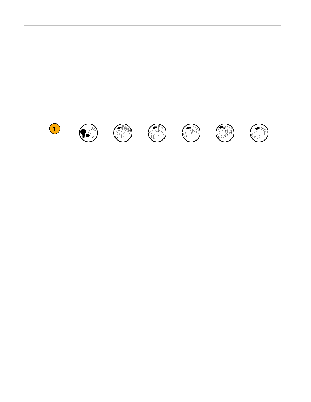
Icons
The following icons are used throughout this manual.
dules have a GPS receiver that can receive both GPS and GLONASS signals. The term “GPS” is used
Sequence
Step
Front panel
power
Connect
power
Network
PS2 SVGA USB
xii SPG8000 Quick Start User Manual
Page 21
Installation
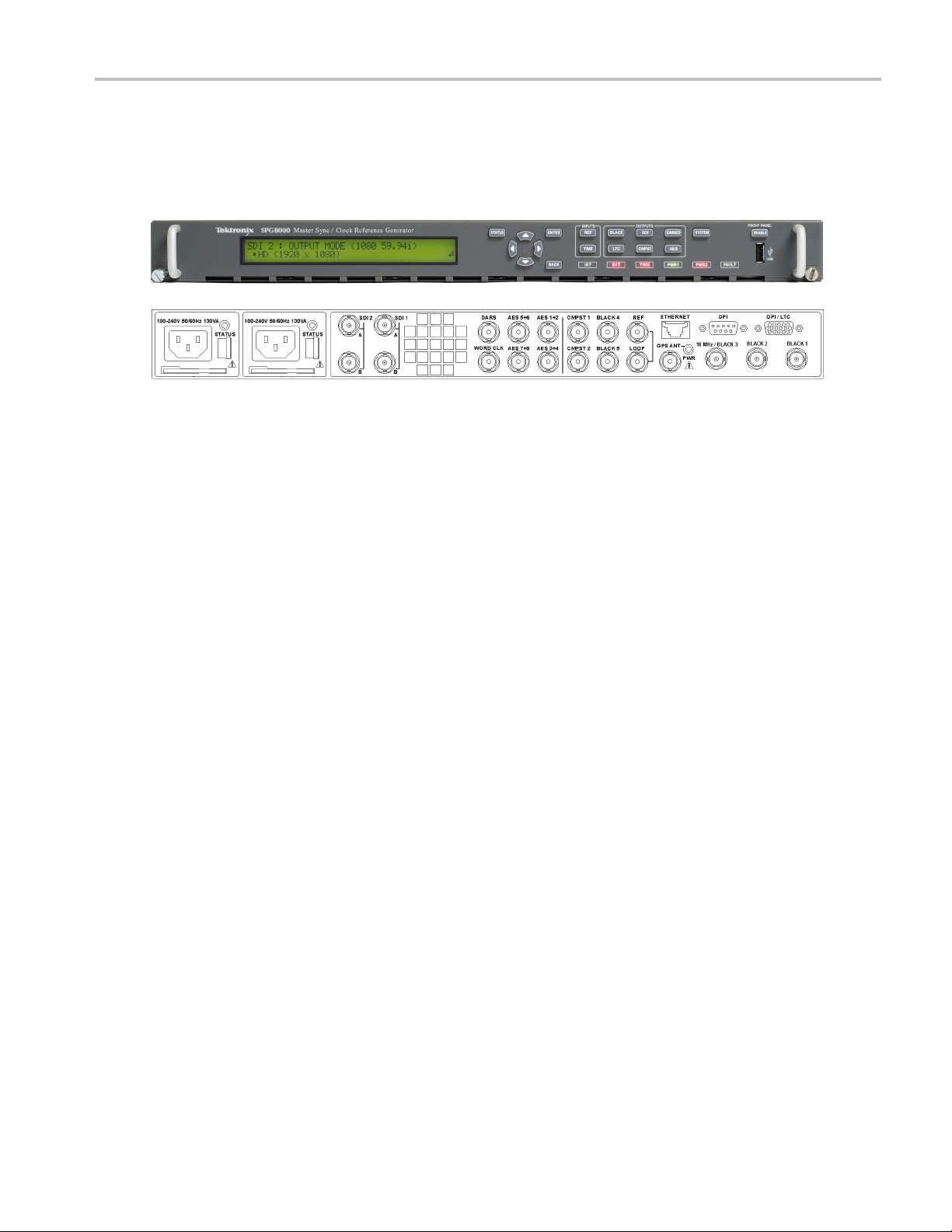
Product description
Figure 1: S PG8000 Master Sync / Clock Reference Generator front and back panels
The SPG8000 is a precision multi-format video signal generator, suitable for master synchronization and reference
applications. It provides multiple video reference signals, such as black burst, HD tri-level sync, and serial digital and
composit
e analog test patterns, and it provides time reference signals such as time code and NTP (Network Time Protocol).
Installation
The base c
black burst and/or HD tri-level sync) and independently adjustable timing offsets. With the BG option, four more analog
outputs can be added. A high-accuracy, oven-controlled crystal oscillator provides a stable frequency reference for the
system,
signal. The SPG8000’s Stay GenLock
disturbance, by maintaining the frequency and phase of each output signal. When the external reference is restored, Stay
GenLoc
instead of “jamming” back to the correct phase.
Time reference outputs are available in multiple formats. Three independent linear time code (LTC) outputs are available,
and a fourth LTC connection can b e used as input or output. Each LTC output has independent frame rate selection, time
sourc
PAL black output, also with independent time sources and offsets. The SPG8000 can also serve as a Network Time Protocol
(NTP) server, providing the time-of-day reference to network-attached devices.
Opti
The GPS option adds an internal GPS/GLONASS receiver to the SPG8000. When connected to an external antenna that
supplies the standard GPS and/or GLONASS RF signal, the SPG8000 can utilize the GPS/GLONASS system’s stable
frequency reference. The GPS and/or GLONASS signal also includes a precise time-of-day reference that can be used for all
time code outputs. Similar to the Stay GenLock
the GPS and/or GLONASS signal is interrupted, and the Holdover Recovery mode will ensure a shock-free re-alignment of
frequency and phase when the GPS and/or GLONASS signal is restored.
Earlier versions of the GPS module included a receiver that could receive only GPS signals. Later versions of the GPS
module include a receiver that can receive both GPS and GLONASS signals. See GPS receiver types to determine which
type of GPS receiver is installed in your instrument. (See page 12.)
onfiguration includes three sync outputs that can be configured with independent output formats (NTSC/PAL
or the loop-through genlock input can be used to lock to an external video reference or 10 MHz continuous wave
®
k
ensures that any accumulated clock drift is removed by slowly adjusting the system clock within standard limits
e (time-of-day or program time) and time zone offset. Vertical interval time code (VITC) is available on each NTSC or
®
feature avoids “synchronization shock” if the external reference suffers a temporary
onal GPS receiver
®
feature, the SPG8000 can maintain the video frequency and phase when
SPG8000 Quick Start User Manual 1
Page 22

Installation
Test signal outputs
The SPG8000 can be optionally configured with a variety of test signal outputs. Option BG adds two additional black outputs
and adds two composite analog outputs (NTSC or PAL) that can be used to generate test patterns such as color bars, or serve
as additional black burst outputs. Option SDI adds two fully independent serial digital video generator channels of two outputs
each. Each channel can be configured to any standard SD or HD-SDI format and frame rate. The selected test pattern can
be generated on both outputs per channel, or one output can generate digital black. Option 3G extends the functionality of
the SDI test signal outputs by adding 3 Gb/s SDI formats. A wide variety of standard test patterns are included, such as color
bars, convergence grid, step scales, ramps, multiburst, SDI pathologica l test matrix and a real-time programmable zone plate
generator. Bitmap images can be downloaded to the SPG8000’s flash memory for arbitrary user-defined test patterns. ID
text, burn-in time code, circle, and color logo overlays can be added to any test pattern, and several ancillary data packet
types, including ancillary time code and user-defined packets, c an be inserted into the SDI output signal.
Audio Reference Sig nals
Several audio reference signals are available on the SPG8000. The base configuration includes a 4 8 kHz word clock output,
and option
and the other four pairs are used for test tone generation, with independent tone frequency and amplitude settings for each of
the 8 channels. Audio tone generation is also included with the SDI option, as embedded audio on each of the SDI outputs.
AG adds five AES/EBU output pairs. One pair is dedicated to a Digital Audio Reference Signal (DARS) output,
Remote A
The SPG8000 includes a 10/100/1000BASE-T Ethernet interface for remote access to the instrument. A web-based user
interface can be used for all configuration settings and for monitoring system status. Alarm and key s tatus information is
also available via Simple Network Management Protocol (SNMP) messaging, enabling easy integration with network
management systems. Remote control and alarm reporting is also available via a general purpose interface (GPI). The
SPG8000 has a front-panel USB port that can be used to backup and restore presets and other user data, and to perform
system firmware upgrades.
ccess
Optional Backup P ower Supply
For critical applications, the SPG8000 can be configured with a second power supply module. Under normal operation, the
nated backup supply is seldom used, ensuring that it has maximum remaining life should the primary supply fail. The
desig
backup supply is load-tested once each day to verify that it can serve as the primary supply if necessary. The usage time of
each supply is logged as “temperature-weighted hours”, a metric that best estimates the calculated life of the supply. A
t-panel LED will indicate when the supply is nearing its end-of-life. If the primary supply is interrupted for any reason, the
fron
system will switch to the backup without any disruption to system operation. Power supply modules are hot-swappable for
easy replacement, and feature a locking mechanism to prevent the power cable from accidental disconnection.
2 SPG8000 Quick Start User Manual
Page 23

Key features
Multiple independent black burst and HD tri-level sync outputs provide all the video reference signals required in a
video broadcast or production facility
Four LTC outputs, VITC on black burst outputs, and NTP server provide time reference signals in a variety of formats;
the NTP server requires Option GPS
GPS and GLONASS-based synchronization gives an accurate time-of-day reference and deterministic video phase
reference, and locks remote SPG8000 systems to each other
Stay GenLock®and GPS Holdover Recovery prevent synchronization shock when the external reference input or
GPS/GLONASS signal is temporarily lost
Wide selection of video test patterns in serial digital formats (SD, HD and 3G-SDI) and composite analog formats
(NTSC and PAL); 3G-SDI test patterns require Option 3G
Dual hot-swappable power supplies ensure continuous availability of reference signals
Easy to manage with Web-based interface for remote configuration and SNMP for status and alert information
Applications
Sync pulse generator and time reference generator for broadcast, studio, mobile, and post-production facilities
Installation
Master or slave (genlock) operation for distributed system architectures
Video equipment verification, facility link testing, and display calibration
SPG8000 Quick Start User Manual 3
Page 24

Installation
Accessories
The following table lists the standard and optional accessories provided with the SPG8000 generator.
Table 1: Standard and optional accessories
Accessory Std. Opt.
SPG8000 Quick Start User Manual (English)
Note: Japanese and Russian language versions of this document
are available in PDF format on the Product D ocumentation CD
SPG8000 Product Documentation CD
Rackmounting hardware
Rackmount installation instructions
Power cord
(See page 4, International power cord options.)
D-sub to XLR/BNC adapter cable (Option XLR only)
GPS/GLONASS rooftop antenna (5.0 VDC, 1588 MHz range signals, F connector) for
GPS and GLONASS satellites
1
This 6 fo
and three BNC male connectors (for General Purpose Interface (GPI) input/outputs).
2
For a replacement cable, order SPG8UP Option XLR.
3
The antenna works with the integrated internal GPS/GLONASS receiver of a SPG8000 with Option GPS.
Tektronix
part number
●
●
●
●
●
071-3080-xx
063-4474-xx
351-1137-00
071-2746-xx
Varies by
option
1
●
●
3
ot adapter cable connects from the 15‐pin D‐sub GPI/LTC connector on the SPG8000 to four XLR male connectors (for LTC input/outputs)
2
NA
SPG8000ANT
International power cord options
All of the available power cord options listed below include a lock mechanism except as noted to keep the power cord
hed to the instrument.
attac
0 – North America power (standard)
Opt. A
1 – Universal EURO power
Opt. A
A2 – United Kingdom power
Opt.
A3 – Australia power
Opt.
A5 – Switzerland power
Opt.
. A 6 – Japan power
Opt
. A10 – China power
Opt
. A11 – India power (no locking power cord)
Opt
t. A12 – Brazil power (no locking power cord)
Op
t. A99 – No power cord
Op
4 SPG8000 Quick Start User Manual
Page 25
Initial product inspection
Perform the following product inspection procedure when you receive your instrument:
1. Inspect the shipping carton for external damage, which may indicate damage to the instrument.
2. Remove the SPG8000 generator from the shipping carton, and then check that the instrument has not been damaged in
transit. Prior to shipment the instrument is thoroughly inspected for mechanical defects. The exterior should not have
any scratches or impact marks.
NOTE. Save the shipping carton and packaging materials for instrument repackaging in case shipment becomes necessary.
3. Verify that the shipping carton contains the instrument, the standard accessories, and any optional accessories that you
ordered. (See Table 1.)
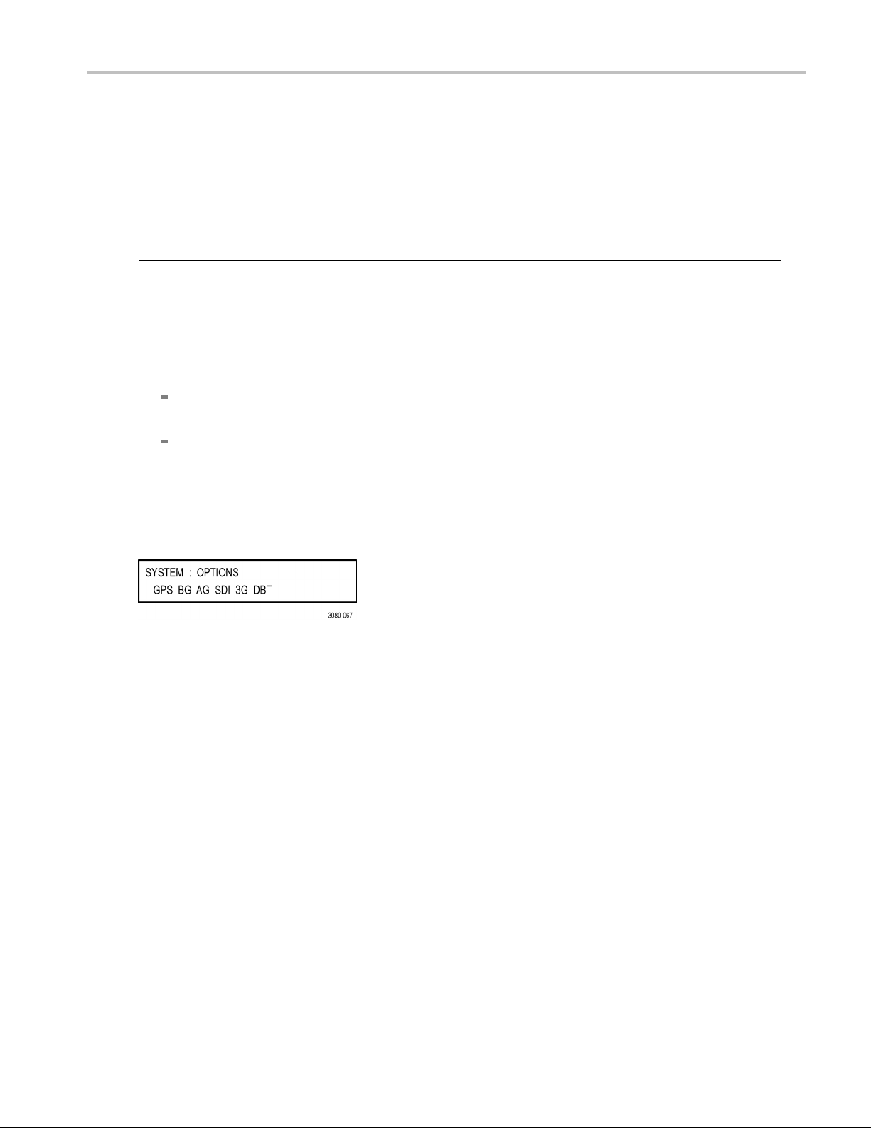
4. Verify that all of the product options that you ordered are installed:
Before installation, you can verify the hardware options by viewing the rear panel. (See Figure 5 on page 42.) After
installation, use the SYSTEM : OPTIONS menu selection to view which options are installed (GPS, BG, AG, and SDI).
If you ordered Option 3G and/or DBT when you purchased the instrument, these software option(s) should already
be enabled and you should have received a document showing the option key. After the instrument is installed, use
the SYSTEM : OPTIONS menu selection to verify that the option(s) is enabled. If you need to enter the option key,
see How to enter the option key (Options 3G and DBT only). (See page 85.)
Installation
The following example display shows all of the available hardware options (GPS, BG, AG, SDI) and software
options (3G, DBT) that may be installed.
Contact your local Tektronix F ield Office or representative if there is a problem with your instrument or if your shipment is
incomplete.
SPG8000 Quick Start User Manual 5
Page 26
Installation
Product installation
This section provides installation information for the SPG8000 generator.
Rackmount installation
WARNING. Personal injury or damage to the instrument can occur if the instrument is not properly secured in the equipment
rack.
The SPG8000 is configured at shipment for use in an equipment rack. Refer to the Rackmount Slides and Rails Kit
Instructions, Tektronix part number 071-2746-XX, that was supplied with the instrument for instructions on how to install
the rackmounting hardware.
To install the instrument into an equipment rack. After you have installed the rackmounting hardware, perform the
following steps to
WARNING. To prevent injury during product installation, use care not to pinch hands or fingers in the rails and slides.
install the instrument into an equipment rack:
1. Insert the instrument le
upward. (See Figure 2.)
NOTE. Make sure to insert the instrument slides inside the inner rack rails. You may also need to tilt the rear of the
instrument up or down a
2. Push the instrument into the rack until it stops.
CAUTION. To prevent damage to the instrument and rackmount, do not force the instrument into the rack if it does not slide
smoothly. The rails a
3. Retighten any loose screws and push the instrument all the way into the rack. If the tracks do not slide smoothly,
readjust the rail assemblies.
4. When adjusting is completed, tighten all rail assembly 10-32 screws using 28 inch-lbs of torque.
5. If the instrument has knob screws on the front corners, tighten them so that they are secured in the rack.
6. To remove the instrument from the rack, loosen the knob screws.
ft and right slides into the ends of the rack rails while tilting the long handle part of each lever
t a slight angle to fit the slides into the rails.
ssembly may need to be adjusted to resolve the problem.
6 SPG8000 Quick Start User Manual
Page 27
Installation
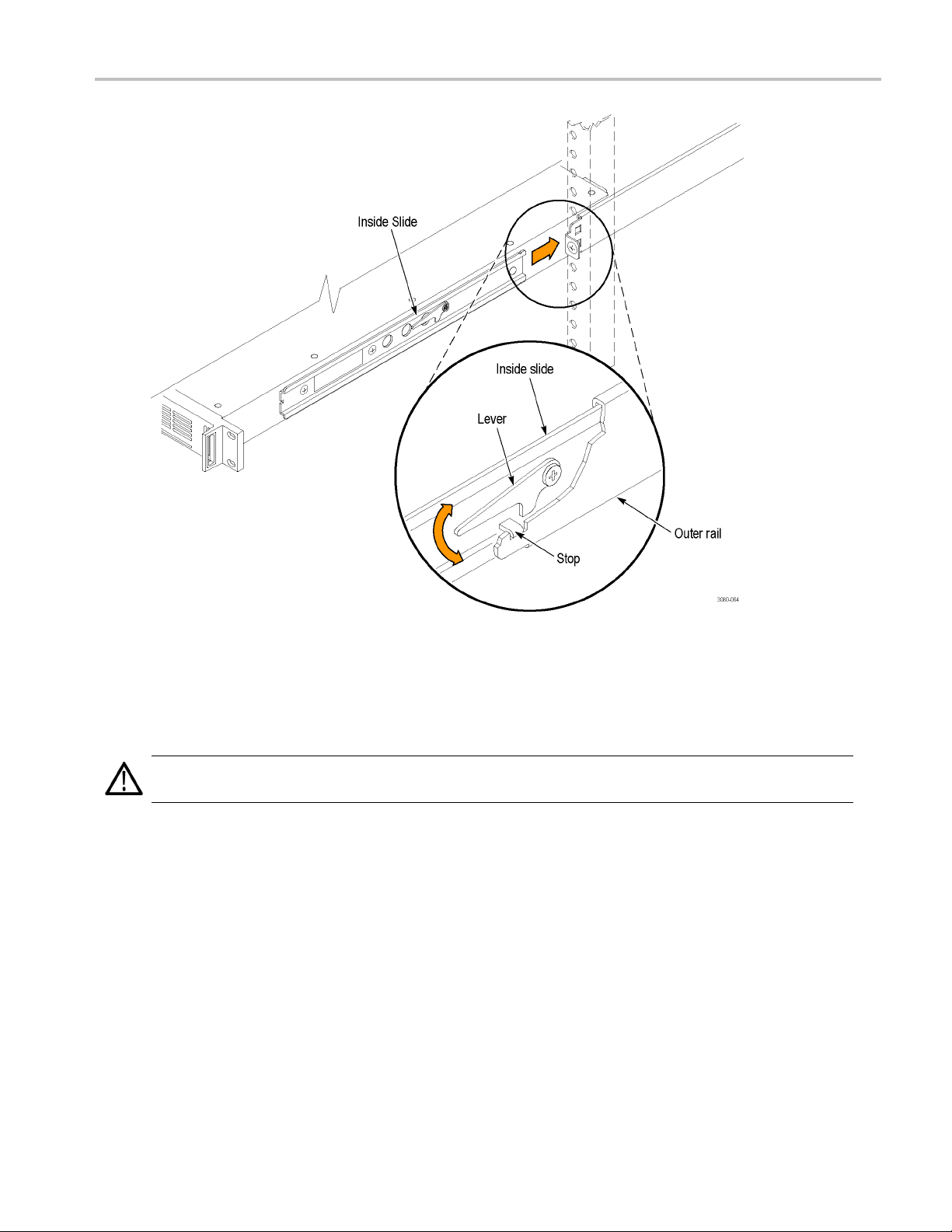
Figure 2: Installing or removing the instrument into or from the rack
To remove the instrument from an equipment rack. Perform the following steps to remove an instrument that
talled in an equipment rack:
is ins
WARNING. To prevent injury when removing the product from the rack, do not forcefully and abruptly pull the product from
the rack. Pull with the minimum force required to move the instrument with a consistent, even motion.
1. Loosen the k
2. Gently pull
3. Tilt both le
4. Pull the ins
nob screws, if present, that attach the front of the instrument to the rack.
the instrument toward you until you can reach the levers at the rear of the instrument.
ver handles upward simultaneously to allow them to clear the stops. (See Figure 2.)
trument past the stops and out of the rack.
SPG8000 Quick Start User Manual 7
Page 28

Installation
Environmental operating requirements
Check that the location of your installation has the proper operating environment as listed in the following table. (See Table 2.)
CAUTION. Damage to the instrument can occur if this instrument is powered on at temperatures outside the specified
temperature range.
Table 2: SPG8000 environmental requirements
Parameter Description
Temperature
Relative Humidity
Altitude
Operating 0 °C to +50 ° C
Nonoperating
Operating 20% to 80% (No condensation); Maximum wet-bulb temperature 29.4 °C
Nonoperating
Operating To 3,000 m (9,842 feet)
Nonoperating
–20 °C to +60 °C
5% to 90% (No condensation); Maximum wet-bulb temperature 40.0 °C
Maximum operating temperature decreases 1 °C each 300 m above
1.5 km.
To 15,000 m (49,212 feet)
Leave space for cooling by ensuring standard side clearance for rack mounting or 2 inches (5.1 cm) of side clearance for
benchtop use. Also, ensure sufficient rear clearance (approximately 2 inches) so that cables are not damaged by sharp
bends.
For complete specifications for the instrument, refer to the SP G8000 Specifications and Performance Verification Technical
Reference manual.
Firmware upgrades
Tektronix releases product updates to add new features and to fix problems with the product firmware. During installation, it
is recommen
for your product at the Tektronix Web site (www.tektronix.com/downloads). (See page 68, How to upgrade the instrument
firmware.)
ded that you verify your instrument has the latest firmware version installed. You can find the latest firmware
8 SPG8000 Quick Start User Manual
Page 29

Power connection
The SPG8000 operates from a single-phase power source with the neutral conductor at or near earth ground. The line
conductor is fused for over-current protection. A protective ground connection through the grounding conductor in the
locking power cord is essential for safe operation.
The standard instrument has one Power Supply module installed. With Option DPW, a second hot-swappable redundant
(backup) Power Supply module i s installed. When two Power Supply modules are installed in the instrument, one is
configured to be the primary supply and the other is configured to be the backup supply. In the event that the primary supply
fails, the backup supply will automatically provide power to maintain instrument operation. (See page 81, How to operate an
instrument with two power supplies (Option DPW only).)
CAUTION. The instrument does not have a power switch. When you connect the power cable to the AC line connector,
the instrument powers on.
Do not install or remove a Power Supply module when a power cord is attached to that module.
AC power requirements
Check that your location provides the proper electrical power requirements as listed in the following table. (See Table 3.)
Installation
Table 3: A
Paramete
Line Voltage Range
Line fr
Maximum power 130 VA
C line power requirements
r
equency
Descript
100 - 240
WARNING. To reduce the risk of fire and shock, ensure
that the mains supply voltage fluctuations do not exceed
10% of t
50/60 H
ion
VAC
he operating voltage range.
z
To connect the power cable(s)
Connect the power cable to the instrument first, and then connect it to the AC power source. Connecting the power cable
causes the instrument to power on.
After the instrument boots up and initializes, make sure that the FAULT indicator is not illuminated and than no faults are
reported on the instrument display. If the FAULT indicator is illuminated, perform the appropriate user action. (See Table 8
on page 40.)
Backup supply (Option DPW). If the instrument has two Power Supply modules installed (Option DPW), connect a
er cable to each of the supplies. After the instrument powers on, configure the instrument for the preferred (active)
pow
supply. (See page 81, How to operate an instrument with two power supplies (Option DPW only).)
SPG8000 Quick Start User Manual 9
Page 30

Installation
Network installation
The SPG8000 has a 10/100/1000 BASE-T Ethernet port on the rear panel that allows you to use a PC to remotely control the
instrument and to upload and download user files such as signal or logo files.
This section provides instructions for connecting the SPG8000 to a single PC or to a network and for setting the network
parameters on the Ethernet port.
See How to transfer user files for instructions on how to upload and download user files using the Ethernet port. (See
page 76.)
Connecting the SPG8000 to your PC(s)
You can use one of the following two methods to connect the SPG8000 to your PC(s):
If you are connecting the SPG8000 directly to a single PC, use an Ethernet cable to connect between the Ethernet
port on the SPG8000 and the Ethernet port on the PC.
If you are connecting the SPG8000 to your local Ethernet network, use an Ethernet cable to connect between the
Ethernet p
you can access the SPG8000 using any PC on the network.
ort on the SPG8000 and the Ethernet hub port of your local network. By connecting to an Ethernet network,
To configure the network parameters
The following two procedures describe how to configure the SPG8000 network parameters. Use the first p rocedure if your
network supports DHCP; use the second procedure if your network does not support DHCP.
To configure parameters for a network with a DHCP server. If your network has a DHCP server, perform the
following steps to configure the instrument to function as a DHCP client. When the SPG8000 is connected to the network
and DHC
NOTE. Under some network environments, the SPG8000 may not be able to get the IP address automatically from a DHCP
server. In this case, you need to enter the appropriate address value in each submenu item.
Refer to your network administrator or to the user documentation supplied with your network server operating system
(OS) f
1. Press the front-panel SYSTEM button to access the SYSTEM menu.
2. Press the up (▲) or down (▼) arrow button to select SYSTEM : NETWORK.
3. Press the left (◄) or right (►) arrow button to s elect Setup, and then press the ENTER button. This accesses the
4. Press the left (◄)orright(►) arrow button to select Enable, and then press the ENTER button.
5. Press the BACK button to exit the NETWORK SETUP submenu.
P service is enabled, the SPG8000 obtains the necessary network addresses automatically from the DHCP server.
or detailed information about DHCP server functions.
NETWORK SETUP submenu. The top line of the display should read SYSTEM : NET SETUP : DHCP.
10 SPG8000 Quick Start User Manual
Page 31

Installation
To configure parameters for a network without a DHCP server. If your network does not have a DHCP server,
perform the fol
lowing procedure to set the network parameters:
1. Press the fron
2. Press the up (▲
3. Press the left
NETWORK SETUP submenu. The top line of the display should read SYSTEM : NET SETUP : DHCP.
4. Press the left (◄) or right (►) arrow button to select Disable, and then press the ENTER button.
5. If you connected the SPG8000 directly to a single PC:
a. Press the up (▲)ordown(▼) arrow button to select SYSTEM : NET SETUP : IP ADDRESS, and then press
the ENTER button to enter the edit mode.
b. Use the arrow buttons to set the IP address to be the same IP address as the PC's address except for the last
number, an
in the PC's IP address.
c. Press the up (▲) or down (▼) arrow button to select SYSTEM : NET SETUP : SUBNET MAS K, and then press
the ENTER button to enter the edit mode.
d. Use the arrow buttons to set the subnet mask to be the same net mask (subnet mask) used by the PC, and then
press the
e. Youdonot
f. Press th
6. If you co
t-panel SYSTEM button to access the SYSTEM menu.
) or down (▼) arrow button to select SYSTEM : NETWORK.
(◄) or r ight (►) arrow button to select Setup, and then press the ENTER button. This accesses the
d then press the ENTER button. The last number in the address must be different than the last number
ENTER button. Do not enter a number if the PC does not have a net mask.
need to enter a GATEWAY address if you are directly connected to a single PC.
e BACK button to exit the NETWORK SETUP submenu.
nnect the SPG8000 to your local Ethernet network, see the Caution note below.
CAUTION. To prevent communication conflicts on your Ethernet network, ask your local network administrator for the correct
numbers to enter in the NETWORK PARAMETERS submenu if you connect the SPG8000 to your local Ethernet network.
7. Verify the Eth
ernet connection by using a ping command from the PC.
SPG8000 Quick Start User Manual 11
Page 32

Installation
GPS and/or GLONASS antenna installation (Option GPS only)
If your instrument has Option GPS installed, you need to connect a GPS and/or GLONASS antenna and check the main
oscillator calibration before you put the instrument into service.
If you o rdered SPG8000ANT, you received a GPS/GLONASS rooftop antenna (5.0 VDC, 1588 MHz range signals, F
connector) for GPS and/or GLONASS signals that works with the integrated internal GPS/GLONASS receiver of a SPG8000
with Option GPS installed.
GPS receiver types
Earlier versions of the GPS module included a receiver that could receive only GPS signals. Later versions of the GPS
module incl
receiver, use the REFERENCE menu to con fi gure the module for the type of signal you are using. (See page 54, REF
button menu diagram.)
ude a receiver that can receive both GPS and GL ONASS signals. If your module has the GPS/GLONASS
How to det
NOTE. Firmware version 1.5 or above must be installed in the instrument in order to view the GPS receiver type readout.
1. Press the SYSTEM button to access the SYSTEM menu.
2. Use the up (▲)ordown(▼) arrow button to select SYSTEM : VERSION INFO (H/W).
3. Use the left (◄)orright(►) arrow button to select the version display with the ID field on the second line of the
displa
ermine which GPS receiver is installed in your instrument.
y as shown below.
ID value is 3015, then the later GPS receiver is installed that can receive GPS and GLONASS signals.
If the
e ID value is 3002, then the earlier GPS receiver is installed that can receive only GPS signals.
If th
12 SPG8000 Quick Start User Manual
Page 33

Installation
Antenna requirements
The SPG8000 generator requires an external antenna to receive GPS and/or GLONA SS signals from satellites. You must
set up an antenna system to provide the GPS and/or GLONASS signal as an input to the SPG8000 generator. You can
configure the instrument to provide 3.3 V or 5 V DC power for the antenna.
WARNING. Prevent risk of shock or fire by ensuring that the GPS and/or GLONASS antenna is protected from lightning
strikes when it is mounted outside a building or facility. The SPG8000 generator does not have isolation protection from
lightning, so the facility installation must provide suitable protection for the GPS and/or GLONASS antenna external to the
instrument. Failure to use appropriate precautions can result in injury or death.
CAUTION. To avoid antenna damage, do not turn on the DC antenna power until you know that the antenna is designed to
handle the selected voltage. Antenna damage can occur if the antenna is not designed to handle the voltage you select.
The frequencies for GPS and GLONASS signals are slightly different. Be sure to choose an antenna that supports all of
the satellite constellations you intend to use. It is recommended that you use an antenna that can receive both GPS and
GLONASS signals. This allows the instrument timing to be more stable since a GPS/GLONASS antenna can communicate
with more satellites.
When a GPS and/or GLONASS feed is first connected to the antenna input on the SPG8000 generator, it can take several
minutes for the signal quality to reach its nominal potential. How long that takes depends on such things as antenna site,
cable plant design, and available satellites. Excluding those variables, the typical tim e to acquire satellites and achieve
specified stability with a good satellite signal, known position, and a warmed up instrument, is two minutes.
Antenna system
a systems vary depending on the operating environment and on safety and regulatory requirements. A simplified
Antenn
typical system is shown in the following figure to help you with planning and understanding the trade-offs of one set up versus
another. (See Figure 3.)
Figure 3: Simplified GPS/GLONASS antenna system
A GPS and/or GLONASS specific antenna with amplifier provides sufficient gain to drive a reasonable length of cable, and
provides filtering to reject signals at other frequencies. A typical example of this for GPS signals is the Trimble Bullet III,
35 dB, 5 V, antenna.
In a simple system without the optional booster, Cable 1 connects the antenna to the SPG8000 generator. The length of
this cable is limited by its attenuation at the carrier frequency (GPS: 1575 MHz, GLONASS: 1602 MHz). The SPG8000
generator should have a signal that is 18 dB or greater above the ambient level. For example, for a 35 dB antenna, the
allowed cable loss is 35 – 18 = 17 dB. (See Figure 3.)
SPG8000 Quick Start User Manual 13
Page 34

Installation
Cables. Attenuation varies significantly depending on cable type. Cable loss is about 13 dB/100 ft for a miniature coaxial
cableliketheB
allowable length of 130 ft for the small cable, to over 300 ft for the larger cable.
A booster amplifier can be added if more length is needed, as shown in the optional block in the signal path system.
(See Figure 3.)
Ifa20dBamplifier is added, then 20 dB more cable l oss can be accommodated. This equates to another 150 ft of small
coax, or 360 f
elden 1855, while for a RG11 style like the Belden 7731, the loss is only 5.5 dB/100 ft. This correlates to an
t of large coax.
Although the
most installations. The reflections from the impedance mismatch will not cause s ignificant changes in the system because
the signal is narrow band and the cable loss is usually many dBs. However, you should not mix short cable lengths of
different i
GPS/GLONASS input and most of the other components are 50 Ω, either 50 Ω or 75 Ω cablescanbeusedin
mpedances, as this might create reflections with the potential to cause signal degradation.
Amplification. The SPG8000 generator provides either 3.3 V or 5 V DC power to drive the amplified antenna and
booster amplifier. The power is carried on the same coax as the GPS and/or GLONASS signal, and can be turned off if the
antenna is powered by a separate supply. When you are designing the antenna system, check the voltage and current
requirements of the components to insure compatibility.
The location of the booster amplifier is important. It needs to be before the second length of cable shown in the simplified
antenna system diagram. If the booster amplifier is placed just before the SPG8000 generator, then the signal will have been
attenuated too far and the output may be noisy. If you cannot put the optional booster amplifier in the middle of a long run of
cable, then put it near the antenna rather than near the SPG8000 generator end.
For more complex systems, a variety of booster amplifiers, powered and passive splitters, DC blocks, and filters are
available from a number of vendors.
Antenna location. It is important that the GPS and/or GLONASS antenna location has a clear view of a large part of the
sky. Since GPS and GLONASS satellites are constantly orbiting the earth, they may be in any direction at a given time. If
the sky is blocked by buildings, trees, mountains, etc., then fewer satellites will be visible. It is also possible to get
part of
reflected signals that will have come by a longer path than expected and thus may degrade timing accuracy and stability.
When evaluating a site, it is important to monitor it over several days and with a variety of weather conditions present.
This antenna information is not intended to cover all aspects of the antenna system design. Important topics that were not
d include items like lightening protection and drip loops. For information about the cable plant design in your system,
covere
contact the appropriate person or group in your organization, or contract with a qualified installer.
Check the oven oscillator calibration
You should not need to adjust the oven oscillator frequency immediately after the initial installation since the oscillator
frequency was adjusted accurately at the factory. However, you can adjust the oscillator frequency at any time to improve the
accuracy of the internal frequency. When Option GPS is installed, you may be able to improve the accuracy slightly after
installation since the instrument will be at the normal temperature for your specific installation site. The steps for checking the
oscillator accuracy are included in the oven calibration procedure. (See page 15, O ven oscillator calibration.)
GPS constellation configuration
u can use the REFERENCE menu to confi gure the instrument for the type of satellite constellations you want the
Yo
instrument to use. If your antenna can receive both GPS and GLO NAS S signals, it is recommended that you configure
the instrument to use both GPS and GLONASS signals. This allows the instrument timing to be more stable since a
S/GLONASS antenna can communicate with more satellites.
GP
14 SPG8000 Quick Start User Manual
Page 35

Oven oscillator calibration
You can calibrate the internal oscillator frequency at any time after you install the instrument in its operating environment
and allow it to reach a stable operating condition. When the instrument is locked to a GPS/GLONASS reference, you can
perform this calibration while the instrument is in service.
This adjustment stores the current frequency of the master clock oscillator for use when the instrument is set to Internal
mode. You can calibrate the internal oscillator frequency at any time after you install the instrument in its operating
environment and allow it to reach a stable operating condition.
NOTE. It is recommended that you perform the internal oscillator frequency calibration at least once a year to compensate
for oscillator drift.
Check if calibration is needed
While locked to a G PS/GLO NA SS reference, perform the following steps to determine if the oven oscillator needs to
be calibrated.
1. Press the SYSTEM button to access the SYSTEM menu.
2. Press the up (▲) arrow button to select SYSTEM : DIAGNOSTICS.
3. Press the ENTER button to access the DIAGNOSTICS menu.
Installation
4. Check that Fine is showing on the right side of the TUNE readout on the LCD display.
5. Check the Tune readout value. If the value is greater than ±0.10e–6, then you need to calibrate the oven oscillator. If the
s less than ±0.10e–6, then no calibration is required.
value i
NOTE. Even if the value is less than ±0.10e–6 and no calibration is required, you may want to calibrate the oven oscillator
anyway to ensure maximum accuracy and to postpone the need for a calibration in the future.
6. Press
the BACK button to exit the DIAGNOSTICS menu.
Adjustment methods
You can calibrate the oscillator using GPS, GLONASS or reference signals such as NTSC Burst or CW. If you are not using
a GPS or GLONASS reference signal, the reference signal from a frequency signal generator must be at the correct
frequency. Procedures for using either method are provided.
If your SPG8000 generator has Option GPS installed, you should use a GPS or GLONASS signal to adjust the master clock
frequency. When you use a GPS or GLONASS signal to adjust the master clock, the calibration can be performed while the
instrument is in service, which avoids any system downtime or any warm-up period.
If you do not have Option GPS installed or if you do not have access to a GPS or GLONASS signal, you will need to take the
instrument out of service to adjust the master clock using an input from a frequency generator.
SPG8000 Quick Start User Manual 15
Page 36

Installation
How to adjust the oven oscillator using GPS and/or GLONASS
If your SPG8000 has Option GPS installed, perform the following procedure to use GPS and/or GLONASS to set the internal
frequency of the instrument internal oscillator. This procedure can be done without any disruption to operation and is best
performed in the operating environment of the instrument.
CAUTION. For instruments in service: To prevent inaccurate cali bration, be sure the instrument is warmed up and locked
to a GPS and/or GLONASS signal for at least 20 minutes before you perform this procedure. The instrument requires a
20 minute warm-up time in a +20 °C to +30 °C environment before it is adjusted. Adjustments done before the operating
temperature has stabilized may cause errors in performance.
1. Press the STATUS button to access the STATUS menu.
2. Use the up (▲)ordown(▼) arrow button to check that there are no faults or alerts reported.
3. If you are adjusting the oven oscillator with the instrument in service, proceed to step 12. Otherwise, perform the next step.
CAUTION. To prevent problems with the output signals, do not perform steps 4-9 w hile your instrument is in service.
4. Press the REF button to access the REFERENCE menu.
5. Press the left (◄) or right (►) arrow button to select GPS Signal as the reference source.
6. Press the ENTER buttontoconfirm the selection. A bullet appears in front of the readout to indicate the current selection.
7. Press the up ( ▲) arrow button to select REFERENCE : GPS CONSTELLATION.
8. Press the left (◄) or right (►) arrow button to select GPS & GLONASS.
9. Press the ENTER buttontoconfirm the selection. A bullet appears in front of the readout to indicate the current selection.
10. Let the instrument warm up for 20 minutes with the GPS signal connected before proceeding.
11. Press the STATUS button to access the STATUS menu.
12. Press the up (▲) arrow button to select STATUS : REFERENCE : GPS.
13. Check that the status readout shows Locked.
14. Check the signal lock indicator and check the tune setting:
a. Press the S YSTE M button to access the SYSTEM menu.
b. Press the up (▲) arrow button to select SYSTEM : DIAGNOSTICS.
c. Press the ENTER button to access the DIAGNOSTICS menu.
d. Check that Fine is showing on the right side of the TUNE readout on the LCD display.
e. Press the BACK button to exit the DIAGNOSTICS menu.
15. Press the up (▲) arrow button to select SYSTEM : CALIBRATE OVEN.
16 SPG8000 Quick Start User Manual
Page 37

16. Press the ENTER button to access the Internal Frequency Calibration submenu.
17. In the Execute Calibration? confirmation display, press the ENTER button to start the calibration.
18. When the calibration is complete, verify that the message “CALIBRATION result = xxxxxxx” is displayed. The result
should be seve
n characters near the value of 2,097,152.
Installation
19. Press the ENTE
20. Press the BAC
21. Verify the ca
a. Press the SY
b. Press the up
R button to exit the calibration mode.
K button to exit the calibration menu.
libration:
STEM button to display the SYSTEM menu.
(▲) or down (▼) arrow button to select SYSTEM : DIAGNOSTICS, and then press the ENTER button
to access the DIAGNOSTICS submenu.
c. Press the up (▲) or down (▼) arrow button to select SYSTEM : DIAGNO STICS : CALIBRATION.
d. Check that the CAL value is less than 2.5 e
NOTE. If the CAL value is greater than 2.6 e
-6
.
-6
, then the oscillator oven may need to be serviced.
How to adjust the oven oscillator without GPS
If your SPG8000 does not have Option GPS installed, perform the following procedure to use a signal generator to set the
internal frequency of the instrument internal oscillator. This procedure requires that you take the instrument out of service in
order to adjust the master clock.
CAUTION. To prevent inaccurate calibration, be sure the instrument is warmed up for at least 20 minutes before you perform
this procedure. The instrument requires a 20 minute warm-up time in a +20 °C to +30 ° C environment before it is adjusted.
Adjustments done before the operating temperature has stabilized may cause errors in performance.
In addition, be sure the signal generator is allowed an appropriate warm-up time to meet the frequency accuracy.
Required equipment. The following table lists the equipment required to adjust the master clock frequency using a
frequency signal generator.
Table 4: Equipment required to adjust the SPG8000 master clock using a signal generator
Item No. Minimum requirement Recommended equipment
Frequency standard 1 Frequency: 10 MHz ±1×10
Amplitude: 8 dBm
75 Ω BNC cable
75 Ω termination
1 Length: 42 inches Tektronix part number 012-0074-00
1 Tektronix part number 011-0163-00
–9
Tektronix GPS7 locked to GPS
and/or GLONASS or equivalent
Spectracom/Pendulum 6689
SPG8000 Quick Start User Manual 17
Page 38

Installation
Procedure. Perform the following steps to use a signal generator to set the frequency of the SPG8000 internal oscillator.
1. Set the output of the frequency generator as follows:
Frequency: 10.000000 MHz
Output level:
8 dBm
2. Use the 75 Ω BNC
generator as shown in the following figure.
NOTE. You can use a Tektronix TG700 or TG8000 signal generator with a GP S7 module i nstalled to produce the 10
MHz frequenc
In this case
output of the GPS7 module to output a 10 MHz sine wave. Connect the GPS7 module B lack 3 output to the REF input
on the SPG8000 you are testing.
Figure 4
3. Connect a 75 Ω termination to the other REF connector on the SPG8000 generator.
4. Restart the instrument in Factory mode:
y standard.
, ensure that the GPS7 module is locked to a GPS or GLONASS signal in fine mode. Configure the Black 3
: Connection for adjusting the SPG8000 master clock using a frequency generator
cable to connect the REF connector on the SPG8000 generator to the output of the frequency
a. Press and hold the STATUS, ENTER, and Front Panel ENABLE buttons simultaneously.
b. Continue holding the buttons until the message SPG8000 Booting... displays.
c. When the message SPG8000 Booting... displays, release the STATUS and ENTER buttons. Continue holding the
Front Panel ENABLE button.
d. When the message SPG 8000 Start up with Factory Mode displays, release the Front Panel ENABLE button.
5. Let the instrument warm up for 20 minutes before proceeding.
6. Set the reference source to CW as follows:
a. Press the REF button to display the REFERENCE menu.
b. Press the left (◄)orright(►) arrow button to select CW, and then press the ENTER button.
c. Check that the front-panel EXT LED is solid green, indicating that the instrument is locked to the signal.
7. Press the SYSTEM button to display the SYSTEM menu.
8. Press the up (▲)ordown(▼) arrow button to select SYSTEM : CALIBRATE OVEN, and then press the ENTER button.
9. A message will be displayed asking you to verify that you want to execute the calibration. Press the ENTER button
to proceed with the calibration.
18 SPG8000 Quick Start User Manual
Page 39

10. Verify that the message CALIBRATION result = xxxxxxx is displayed. The result should be seven characters near
the value of 2,0
97,152.PresstheENTER button to exit the calibration mode.
Installation
11. Verify the cal
a. Press the SY ST
b. Press the up (▲
ibration:
EM button to display the SYSTEM menu.
) or down (▼) arrow button to select SYSTEM : DIAGNOSTICS, and then press the ENTER button
to access the DIAGNOSTICS submenu.
c. Press the up (▲) or down (▼) arrow button to select SYSTEM : DIAGNO STICS : CALIBRATION.
d. Check that the CAL value is less than 2.5 e
NOTE. If the CAL value is greater than 2.6 e
-6
.
-6
, then the oscillator oven may need to be serviced.
SPG8000 Quick Start User Manual 19
Page 40

Installation
Functional checks
Use the following procedures to check that the hardware options installed in your SPG8000 generator are functional. Some
of the procedures depend on which options are installed in your instrument.
Preparation
Perform the following steps before you perform the functional check procedures:
1. Power on the SPG8000 generator by connecting it to the power source. The initialization process for all of the installed
hardware options is executed.
2. Check that no error messages appear on the LCD display.
3. Warm up the instrument for 20 minutes.
CAUTION. To prevent inaccurate results, be sure to warm up the instrument for 20 minutes before you perform any of
the functional check procedures.
Diagnostics check
Use the following procedure to check that the BLACK signal outputs are functional:
1. Press the SYSTEM button to access the SYSTEM menu.
2. Press the up ( ▲)ordown(▼) arrow button to select SYSTEM : DIAGNOSTICS.
3. Press the ENTER button to access the DIAGNOSTICS menu.
4. Use the arrow buttons to navigate through the diagnostic displays. The up (▲) and down (▼) arrow buttons select
different diagnostic c ategories. The left (◄) and right (►) arrow buttons select additional pages of information
for many diagnostic c ategories.
5. Option SDI only: Check that the status for each of the DDS and PLL displays read Lock or Lk.
NOTE. There are additional SDI diagnostics for checking the DDR2 and SRAM memory that can be accessed only in factory
mode. See the SPG8000 Service Manual for information on using the factory mode.
6. Check that all of the temperature readouts are within range or report a status of OK.
NOTE. For instruments with Option GPS and a GPS/G LONASS receiver, the REF Board temperature is reported as N/A
since that receiver does not have a temperature sensor. (See page 12, How to determine which GPS receiver is installed
in your instrument.)
7. Check that the status of all voltage readouts are OK.
8. Check that the status of the fan speed readouts are OK.
9. Option GPS only: Check that the status of the GPS phase ramp readouts are OK.
10. If any of the diagnostics report a problem, service the instrument before proceeding with the functional checks.
20 SPG8000 Quick Start User Manual
Page 41

Installation
BLACK output formats and frame pulse functional check
Use the following procedure to check that the BLACK signal formats a re functional:
Required equipment.
Television signal generator with black burst and HD SDI outputs
NTSC/PAL/SDI w aveform monitor
75 Ω BNC cable
Procedure.
1. Connect an HD SDI signal, like one from an HDVG7 or SDI7 module in a TG700 or TG8000 generator, to the SDI A
input of a WFM8300, and select that input as the active input on the waveform m onitor. You can use any HD SDI
signal (for example, 1080i 59, 1080i 50, or 1080p 24).
2. Connect a cable from the BLACK 1 output on the SPG8000 generator to the reference input of the WFM8300. Terminate
the loopthrough connector on the monitor with a 75 Ω terminator.
3. Press the EXT REF button on the WFM8300.
4. Set the format of the BLACK 1 output to PAL:
a. Press the BLACK button on the SPG8000 generator to select BLACK 1 : FORMAT.
b. Use the left (◄)orright(►) arrow button to select PAL.
c. Press the ENTER button. A bullet will appear in front of the PAL readout to indicate the current format selection.
5. Check that the WFM8300 shows PAL as the reference input.
6. Set the HD tri-level sync r ate to Non-Integer for the BLACK 1–3 outputs:
a. Press the BLACK button repeatedly to select BLAC K 1-3 : HD TRI-LEVEL SYNC RATE.
b. Press the right (►) arrow button to select Non-Integer (59.94, 29.97, 23.98)).
c. Press the ENTER button. A bullet will appear in front of the Non-Integer readout to indicate the current rate selection.
7. Set the format of the BLACK 1 output to 1080 59.94i:
a. Press the BLACK button to select BLACK 1 : FORMAT.
b. Use the left (◄)orright(►) arrow button to select 1080 59.94i as the format of the BLACK 1 output.
c. Press the ENTER button. A bullet will appear in front of the 1080 59.94i readout to indicate the current format
lection.
se
eck that the WFM8300 shows a 1080 59.94i signal on the reference input.
8. Ch
SPG8000 Quick Start User Manual 21
Page 42

Installation
9. Set the HD tri-level sync rate to Integer for the BLACK 1–3 outputs:
a. Press the BLACK button repeatedly to select BLACK 1-3 : HD TRI-LEVEL SYNC RATE.
b. Press the right (►) arrow button to select Integer (60, 50, 30, 25, 24).
c. Press the ENTER button. A bullet will appear in front of the Integer readout to indicate the current rate selection.
10. Set the format of the BLACK 1 output to 1080 60i:
a. Press the BLACK button to select BLACK 1 : FORMAT.
b. Use the left (◄)orright(►) arrow button to select 1080 60i as the format of the BLACK 1 output.
c. Press the ENTER button. A bullet will appear in front of the 1080 60i readout to indicate the current format selection.
11. Check that the WFM8300 shows a 1080 60i signal on the reference input.
12. Check the BLACK 2 output:
a. On the SPG8000 generator, move the signal cable from the BLACK 1 output to the BLACK 2 output.
b. Repeat steps 4 through 11 for the BLACK 2 output.
13. Check the BLACK 3 output:
a. On the SPG8000 generator, move the signal cable from the BLACK 2 output to the BLACK 3 output.
b. Repeat steps 4 through 11 for the BLACK 3 output.
14. Option BG only: Check the BLACK 4 output:
a. On the SPG8000 generator, move the signal cable from the BLACK 3 output to the BLACK 4 output.
b. Repeat steps 4 through 11 for the BLACK 4 output. Be sure to select BLACK 4–5 when you set the HD tri-level
tes.
sync ra
15. Option
BG only: Check the BLACK 5 output:
a. On the S
b. Repea
sync rates.
PG8000 generator, move the signal cable from the BLACK 4 output to the BLACK 5 output.
t steps 4 through 11 for the BLACK 5 output. Be sure to select BLACK 4–5 when you set the HD tri-level
22 SPG8000 Quick Start User Manual
Page 43

Composite outputs functional check (Option BG only)
Use the following procedure to check that the compos ite video outputs (Option BG only) are functional:
Required equipment.
NTSC/PAL waveform monitor
75 Ω BNC cable
Procedure.
1. Press the CMPST button r epeatedly until the CMPST 1 output is selected as shown below.
2. Press the left (◄) or right (►) arrow button to select desired signal format: NTSC or PA L.
3. Press the ENTER buttontoconfirm the format selection. A bullet appears in front of the selected format name as
shown above.
Installation
4. Press the up (▲) or down (▼) arrow button to select CMPST 1 : TEST SIGNAL.
5. Press the left (◄)orright(►) arrow button to select 100% Color Bar.
6. Press the ENTER button to confirm the test signal selection. A bullet appears in front of the selected signal name as
shown above.
7. Connect the CMPST 1 connector to the NTSC/PAL waveform monitor using the 75 Ω BNC cable.
8. Set the waveform monitor to view the signal.
9. Check that the appropriate color bar signal is displayed.
10. Press the CMPST button to select the CMPST 2 output.
11. Repeat steps 1 through 9 for the CMPST 2 output.
SPG8000 Quick Start User Manual 23
Page 44

Installation
SDI outputs functional check (Options SDI and 3G only)
Use the following procedure to check that the SDI outputs (Option SDI only) are functional.
Required equipment.
3 Gb/s waveform monitor
One 1 m (3 ft) BNC to BNC high-bandwidth cable
Procedure.
1. Check the SPG8000 diagnostics. (See page 20, Diagnostics check.) The diagnostics affecting the SDI outputs are
the PLL and DDS status readouts and the SDI Board temperature readouts.
2. Determine if Option 3G is enabled. Some of the steps in this procedure depend on whether the option is enabled or not.
a. Press the S YSTE M button to access the SYSTEM menu.
b. Press the up (▲) or down (▼) arrow button to select SYSTEM : OPTIONS.
c. If 3G appears in the second line of the display as shown below, then Option 3G is installed.
NOTE. If Option 3G is not enabled and you have the option key, you can enter the option key to enable the option. (See
page 85, How to enter the option key (Options 3G and DBT only).)
3. Press the SDI button until the SDI 1 output is selected as shown below.
4. Press the left (◄) or right (►) arrow button to select the appropriate output mode as listed below. When the desired
output mode is displayed, press the ENTER button to confirm the selection.
Option 3G enabled: select the 3G-Level A (1920 × 1080) output mode.
Option 3G not enabled: select the HD (1920 × 1080) output mode.
5. Press the up ( ▲)ordown(▼) arrow button to select SDI 1 : FORMAT. The selected Output Mode will be listed on
the top line of the display.
6. Press the left (◄)orright(►) arrow button to select the appropriate format as listed below. When the desired format is
displayed, press the ENTER button to confirm the selection.
Option 3G enabled: select the 1080 50p format.
Option 3G not enabled: select the 1080 50i format.
24 SPG8000 Quick Start User Manual
Page 45

7. Press the up (▲) or down (▼) arrow button to select SDI 1 : TEST SIGNAL, and then press the ENTER button
to enter the SDI
TEST SIGNAL submenu.
Installation
8. Press the up (▲
(◄) or right (►) arrow button to select a specific test signal to output (such as 100% Color Bars). Press the ENTER
buttontoconfirm the signal selection.
9. Press the BACK button to exit the SDI TEST SIGNA L submenu.
10. Connect the SDI 1A connector to the HDTV waveform monitor using the 75 Ω BNC cable.
11. Set the waveform monitor to view the signal.
12. Check that the signal appears as expected. Check for errors on the video session screen of the waveform monitor.
13. Disconnect the BNC cable from the SDI 1A connector, and then connect the BNC cable to the SDI 1B connector.
14. Press the up (▲)ordown(▼) arrow button to select SDI 1 : FORMAT.
15. Press the left (◄)orright(►) arrow button to select the appropriate format as listed below. When the desired format is
displayed
Option 3G e
Option 3G
16. Check tha
17. Repeat st
to the waveform monitor.
) or down (▼) arrow button to select the test signal type (such as Color Bar), and then press the left
,presstheENTER buttontoconfirm the selection.
nabled: select the 1080 59.94p format.
not enabled: select the 1080 59.94i format.
t the signal appears as expected on the waveform monitor and check for errors on the video session screen.
eps 3 through 16 for the SDI 2 outputs. To test the SDI 2 outputs, connect the SDI 2A and SDI 2B outputs
SPG8000 Quick Start User Manual 25
Page 46

Installation
GPS/GLONASS functional check (Option GPS only)
Use the following procedure to check that the GPS/GLONASS synchronization and timecode functions are operational.
NOTE. Earlier versions of the GPS module have a receiver that can receive only GPS signals. Later versions of the
GPS module have a receiver that can receive both GPS and GLONASS signals. (See page 12, How to determine which
GPS receiver is installed in your instrument.)
Required equipment.
GPS and/or GLONASS antenna feed with good signal level (for example, SPG8000ANT)
Voltmeter
BNC-to-banana-plug adapter
(2) 75 Ω coaxial terminators (Tektronix part number 011-0163-XX)
(2) BNC T connectors
1 meter BNC cable
Procedure.
1. Check the SPG8000 diagnostics. (See page 20, Diagnostics check.) The diagnostics affecting the GPS system are the
REF Boar
2. Load th
a. From th
b. Press t
c. Press
d. Press
e. When t
NOTE. When Option GPS is installed, the Factory Default preset sets the reference source to GP S Signal in the
REFERENCE menu. The following procedures assume the Reference Source setting is configured to GPS Signal.
d temperature and the readouts for the GPS up and down phase ramps.
e factory preset:
e SYSTEM menu, press the up (▲) or down (▼) arrow button to select SYSTEM : PRESET.
he ENTER button to access the PRESET menu.
the left (◄) arrow button to s elect Factory Default.
the ENTER button to load the Factory Default preset.
he preset loading is complete, press the BACK button to exit the PRESET menu.
26 SPG8000 Quick Start User Manual
Page 47

Check the DC antenna output power voltage.
1. Connect the BNC-to-Banana-plug adapter to the voltmeter.
2. Connect the BNC T to the adapter.
3. Connect a 75 Ω BNC cable to the other end of the BNC T connector.
4. Connect the other end of the cable to the GPS and/or GLONASS antenna input on the rear of the instrument. (See
Figure 5 on page 42.)
5. Set the GPS and/or GLONASS antenna power to 3.3 V:
a. Press the REF button to access the REFERENCE menu.
b. Use the up (▲)ordown(▼) arrow button to select REFERENCE : GPS ANTENNA POWER.
c. Use the left (◄) or right (►) arrow button to select 3.3 Volt.
d. Press the ENTER button. A bullet will appear in front of the 3.3 Volt readout to indicate the current power selection.
6. Check that the voltmeter shows between 3.3 V and 4 V.
7. Use the left (◄) arrow to set the GPS antenna voltage to 5Volt.
8. Press the ENTER button. A bullet will appear in front of the 5 Volt readout to indicate the current power selection.
Installation
9. Check that the voltmeter shows between 5 V and 6 V.
Check the antenna current and fault thresholds.
1. Connect
2. Connec
3. If nece
a. Press t
b. Use th
c. Use th
d. Press
4. Conn
5. Conn
6. Chec
Green indicates an open circuit.
7. Apply a 75 Ω terminator to the BNC T and check that the voltage is between 4.5 V and 5 V.
8. Check that the GPS power LED is a steady green. This indicates a nominal load.
the BNC-to-Banana-plug adapter to the voltmeter.
t the BNC T to the adapter.
ssary, set the GP S antenna power to 5 V:
he REF button to access the REFERENCE menu.
eup(▲)ordown(▼) arrow button to select REFERENCE : GPS ANTENNA POWER.
eleft(◄) or right (►) arrow button to select 5Volt.
the ENTER button. A bullet will appear in front of the 5 Volt readout to indicate the current power selection.
ect a 75 Ω BNC cable to the other end of the BNC T connector.
ect the other end of the cable to the GP S antenna input on the rear of the instrument. (See Figure 5 on page 42.)
k that the GPS power LED (located next to the GPS antenna connector on the rear panel) is flashing green.
9. Connect the second BNC T and 75 Ω terminator to the antenna system to exceed the allowed antenna current.
10. Check that the GPS power LED is a steady red. This indicates a short circuit.
11. Remove the terminators and the connection to the voltmeter.
SPG8000 Quick Start User Manual 27
Page 48

Installation
Check the lock to GPS and/or GLONASS through antenna function.
CAUTION. To av
handle the selected voltage. Antenna damage can occur if the antenna is not designed to handle the voltage you select.
1. Set the antenna voltage as needed by the antenna in the test system (3.3 Volt or 5 Volt).
2. Navigate to the GPS signal quality menu:
a. Press the STATUS button to access the STATUS menu.
b. Use the up (▲)ordown(▼) arrow button to select STATUS : GPS. As shown below, the signal quality will read
0.0 and the number of
to the instrument.
c. Use the up (▲) or down (▼) arrow button to select STATUS : REFERENCE : GPS. The status will read No Signal
because there is no GPS and/or GLONASS signal connected to the instrument.
3. Connect the GPS and/or GLONASS input signal feed to the GPS antenna input on the rear of the instrument.
4. Check that the GPS reference status readout changes from No Signal to Low Signal to Acquiring satellites to Adjusting
phase to Locked
oid antenna damage, do not turn on the DC antenna power until you k now that the antenna is designed to
satellites used will read 0/0 because there is no GPS and/or GLONASS signal connected
.
NOTE. It is okay if some steps are skipped. Depending on the signal level, it may take from a few seconds to several
minutes to leave the “No Signal” state.
5. Use the up (▲)
signal quality will read at least 30 and the number of satellites used will read at least 4/4 depending on the number
of satellites being used.
6. Make sure that the instrument has been running for at least 2 0 minutes before performing the next step.
7. Enter the D iagnostics menu and check for “fine” tune status. T his indicates the internal GPS system is operating
at the maxim
a. Press the SY
b. Use the up (▲
c. Press the E
d. Use the up (
right side of the display.
8. Press the BACK button to exit the DIAGNOSTICS menu.
or down (▼) arrow button to select STATUS : GPS. When the GPS reference status is Locked, the
um stability:
STEM button to access the SYSTEM menu.
)ordown(▼) arrow button to select SYSTEM : DIAGNOSTICS.
NTER button to access the DIAGNOSTICS menu.
▲)ordown(▼) arrow button to select TUNE and check that the instrument shows Fine on the
28 SPG8000 Quick Start User Manual
Page 49

Installation
LTC outputs functional check
Use the following procedure to check that the LTC outputs are operational.
Required equipment.
WFM8300 or equivalent with Option CPS
LTC/GPIO breakout adapter cable (Tektronix part number 012-1717-XX)
Female XLR connector, three wires, and one 15-pin, high-density DSUB male header with solder cups, assembled as
described i
Procedure.
1. Connect the LTC/GPIO breakout adapter cable to the GPI/LTC connector on the back of the SPG8000 generator.
2. Construct an adapter by soldering wires between a female XLR and a 15-pin DSUB male header with solder cups, with
this pin out:
a. XLR pin 1 to DSUB pin 6.
b. XLR pin 2 to DSUB pin 7.
c. XLR pin 3 to DSUB pin 8.
n the LTC Output test
3. Connect the LTC 1 output on the breakout cable to the XLR adapter you just made.
4. Connect the DSUB end of the adapter you just made to the remote connector on the WFM8300.
5. Configure the WFM8300 to use LTC as the Timecode source.
6. Configure the LTC 1 output for 30 fps drop frame:
a. Press the LT C button to select LTC 1 : INPUT-OUTPUT.
b. Use the left (◄) or right (►) arrow button to s elect Output (if allowed).
c. Press the ENTE R button. A bullet will appear in front of the Output (if allowed) readout to indicate the current
selection.
d. Use the up (▲) or down (▼) arrow button to select LTC 1 : FOR MAT.
e. Use the left (◄) or right (►) arrow button to select 30fps drop-frame.
f. Press the ENTER button. A bullet will appear in front of the 30fps drop-frame readout to indicate the current selection.
g. Use the up (▲) or down (▼) arrow button to select LTC 1 : SOURCE.
h. Use the left (◄) or right (►) arrow button to select Time of Day.
i. Press the ENTER button. A bullet will appear in front of the Time of Day readout to indicate the current selection.
7. Check that the time of day is correctly updating on the WFM8300 timecode display.
8. Repeat steps 3 through 7 for LTC 2 at 30 fps.
9. Repeat steps 3 through 7 for LTC 3 at 25 fps.
10. Repeat steps 3 through 7 for LTC 4 at 24 fps.
SPG8000 Quick Start User Manual 29
Page 50

Installation
GPI output functional check
Use the following procedure to check that the GPI outputs are operational.
Required equipment.
Television signal generator with an NTSC black burst output
Voltmeter
LTC/GPIO breakout adapter cable (Tektronix part number 012-1717-XX)
9-pin DSUB male header with a wire connected to pin 6
BNC-to-banana-plug adapter
Procedure.
1. Connect an NTSC black burst signal from a television signal generator to one of the R EF loopthrough connectors
on the SPG8000.
2. Terminate the other REF loopthrough connector in 75 Ω.
3. Set the r eference source to NTSC Burst as follows:
a. Press the REF button on the SPG8000.
b. Press the up (▲) arrow button to select REFERENCE : SOURCE.
c. Use the left (◄) or right (►) arrow button to select NTSC Burst.
d. Press the ENTER button.
e. Check that the EXT indicator light on the front panel is green and stable.
4. Connect the GPI 1 output to the voltmeter:
a. Connect the BNC-to-Banana-plug adapter to the voltmeter
b. Connect the LTC/GPIO breakout adapter cable to the GPI/LTC connector on the back of the instrument.
c. Connect the GPI 1 connector on the breakout cable to the BNC-to-B anana-plug adapter.
5. Configure the GPI 1 output to be asserted on unlock:
a. Press the S YSTE M bu
b. Use the up (▲)ordown(▼) arrow button to select SYSTEM : GPI.
c. Press the ENTER button to access the GPI submenu.
d. Use the up (▲)ordown(▼) arrow button to select SYSTEM : GPI : OUTPUT 1.
e. Press the ENTER button to access the GPI OUTPUT 1 submenu.
f. Use the up (▲) or down (▼) arrow button to select Lock Error.
g. Use the left (◄) or right (►) arrow button to select Lock Error: Enable.
tton to access the SYSTEM menu.
.
h. Press the ENTER button. A bullet will appear in front of the Lock Error readout to indicate the current selection.
Press the BACK button twice to exit the GPI submenu.
i.
6. Check that the voltage on the GPI 1 output measures between 4.5 V and 5.5 V.
30 SPG8000 Quick Start User Manual
Page 51

Installation
7. Disconnect the antenna input from the SPG8000 generator. After 15 seconds, check that the GPI 1 output is below 0.5 V.
8. Repeat steps 4 through 7 for the GPI 2 output.
9. To test the GPI 3 output, connect the 9-pin DSUB header to the GPI port on the instrument. Connect the pin 6 wire to a
voltmeter and
connect the ground lead of the voltmeter to the chassis of the S PG8000 generator.
10. Repeat steps 5
through 7 for the GPI 3 output.
GPI input functional check
Use the following procedure to check that the GPI input is operational.
Required equipment.
LTC/GPIO breakout adapter cable (Tektronix part number 012-1717-XX)
75 Ω terminator
Procedure.
1. Configure the GPI input to reset the program time:
a. Press the SY STEM button to access the SYSTEM menu.
b. Use the up (▲)ordown(▼) arrow button to select SYSTEM : GPI.
c. Press the ENTER button to access the GPI submenu.
d. Use the up (▲) or down (▼) arrow button to select SYSTEM : GPI : INPUT TRIGGER.
e. Use the left (◄) or right (►) arrow button to select Reset Program Time.
f. Press the ENTER button. A bullet will appear in front of the Reset Program Time readout to indicate the current
selection.
g. Press the BACK button to exit the GPI submenu.
2. Press the STATUS button to access the STATUS menu.
3. Use the up (▲) or down (▼) arrow button to select SYSTEM : TIME : GPS.
4. Use the left (◄)orright(►) arrow button to display Program Time.
5. Write down the program time.
6. Connect the LTC/GPIO breakout adapter cable to the GPI/LTC connector on the back of the instrument.
7. Attach a 75 Ω terminator to the GPI input for 2 seconds, and then remove it.
8. Look at the program time readout and compare it to the program time you wrote down before. The time on the display
should have reset to the default start time of 00:00:00.00 and now be counting again.
SPG8000 Quick Start User Manual 31
Page 52

Installation
REF loopthrough input functional check
Use the following procedure to check that the Genlock function is operational.
Required equipment.
NTSC black source (can be a second SPG8000 generator, or a TG8000/TG700 mainframe with Option GPS installed)
1 meter BNC cable
75 Ω terminator
Procedure.
1. Set the Reference Source to Internal.
a. Press the REF button to access the REFERENCE menu.
b. Use the left (◄) or right ( ►) arrow button to select Internal.
c. Press the ENTER button. A bullet will appear in front of the Internal readout to indicate the current reference
source selection.
2. Check that the INT indicator on the front panel lights solid green. This shows that the instrument is using the internal
reference signal.
3. Use the left ( ◄) or right (►) arrow button to select NTSC Burst as the reference source.
4. Press the ENTER button. A bullet will appear in front of the NTSC Burst readout to indicate the current reference
source selection.
5. Check that the INT indicator lights solid green and the EXT indicator is solid red. This shows that the is not locked
to any reference signal.
6. Connect the NTSC signal generator output to one of the REF loopthrough connectors using a 75 Ω BNC cable.
7. Connect a 75 Ω terminator to the other REF loopthrough connector.
8. Set the NTSC signal generator to output an NTSC signal.
9. Check that the EXT indicator lights. This shows that the instrument is now using the external reference signal.
10. Disconnect the test setup.
32 SPG8000 Quick Start User Manual
Page 53

Installation
WORD CLOCK output functional check
Use the following procedure to check that the Word Clock output is functional:
Required equipment.
Oscilloscope
75 Ω BNC cable
75 Ω Termination
Procedure.
1. Connect the WORD CLOCK connector to the oscilloscope CH1 input using the 75 Ω BNC cable and 75 Ω termination.
2. Check that the appropriate clock signal is displayed on the screen. The signal will be either 1 V (AC) or 5 V (DC)
depending on the setting in the AES button menu.
NOTE. The 5 V (DC) mode will only provide 2.5 V into a 75 Ω terminator. If you want 5 V, you must remove the 75 Ω
terminator and input the signal into the oscilloscope with the oscilloscope input set to 1 M Ω mode.
AES audio and DARS output functional check (Option AG only)
Use the following procedure to check that the AES audio outputs are functional:
Required equipment.
Digital audio monitor
75 Ω BNC cable
75 Ω Termination
Procedure.
1. Press the front-panel AES button to access the AES menu.
2. Connect the AES 1+2 connector to the digital audio monitor using the 75 Ω BNC cable.
3. Set the digital audio monitor to display the status for the audio data.
4. Check that no CRC errors appears on the monitor and that the signal levels match the settings in the AES button menu.
e default signal amplitude is –20 dBFS.
Th
ve the BNC cable from the AES 1+2 connector to the AES 3+4 connector, and then repeat step 4.
5. Mo
ve the BNC cable from the AES 3+4 connector to the AES 5+6 connector, and then repeat step 4.
6. Mo
ve the BNC cable from the AES 5+6 connector to the AES 7+8 connector, and then repeat step 4.
7. Mo
ove the BNC cable from the AES 7+8 connector to the DARS connector, and check that no CRC errors appear on
8.M
the monitor. The signal levels on the DARS connector should be at the bottom of the graph (less than –70 dBFS) and
should indicate mute on the bars.
SPG8000 Quick Start User Manual 33
Page 54

Operation
Operation
Front panel controls
LCD display
The LCD display is a two-line, 40-character-per-line display. Almost all menus have two lines of text, where the first line
shows the current position in the current menu, and the second line shows the current selection (if there is not a submenu). If
nothing is on the second line, press the ENTER button to access the corresponding submenu.
You can adjust the contrast of the LCD display using the SYSTEM menu. (See page 52, SYSTEM button menu diagram.)
STATUS button
Use the STATUS button to view the status of instrument settings such as the GPS parameters, the format of the black
outputs, the format of the composite outputs, the format of the SDI outputs, and the status of the LTC signals. You can also
view messages explaining the cause of any red or orange fault LEDs on the front panel.
The STATUS button menu allows you to only view information about the settings and state of the instrument. Since no
changes to the instrument operation can be made from this menu, it is always safe to navigate this menu while the
instrument is in operation.
Menu control buttons
Use these buttons to control the menu display. (See page 49, Menu diagrams.)
Arrow (▲), (▼), (◄), and (►) Buttons. Use these arrow buttons to scroll through the available m enu items.
ENTER button. Use the ENTER button to enable the selected menu item or to enter a submenu.
BACK button. Use the B ACK button to return to the previous menu item.
INPUTS
Use these buttons to access menus for controlling the Reference and Time settings in the instrument.
REF button. Use the REF button to access the Reference menu where you can configure the reference source, genlock
timing, and GPS reference settings.
TIME button. Use the TIME button to access the Time menu where you can configure timing settings such as the time of
day, time zone offset, DST schedule, and alarm time and delay.
34 SPG8000 Quick Start User Manual
Page 55

OUTPUTS
Use these buttons to access menus for configuring the signal outputs.
Operation
BLACK button.
outputs. Three Black outputs are standard; there are five Black outputs when Option BG is installed.
Use the BLACK button to configure the format, timing, timecode, and tri-level sync rate of the Black
SDI button. Option SDI is required for this button to operate. Use the SDI button to con figure the output mode and
format of the selected test signal on the optional SDI outputs. You can also enable the moving picture mode, enable and
configure an overlay on the test signal outputs.
n.
EMBED butto
audio on the optional SDI outputs.
Option SDI is required for this button to operate. Use the EMBED button to configure the embedded
LTC button. Use the LTC button to configure the LTC input and outputs on the GPI / LTC connector.
CMPST button. Option BG is required for this button to operate. Use the CMPST button to configure the composite
outputs.
AES button. Option AG is required for this button to operate. Use the AES button to configure the AES audio outputs.
SYSTEM button
Use the SYSTEM button to access the System menu where you configure and view various system settings. You can
save and recall presets, configure the network settings, enable the Web user interface and the SNMP interface, backup
tore instrument settings, view alarms, configure the GPI interface, run and view instrument diagnostics, and
and res
upgrade the instrument firmware.
FRONT PANEL ENABLE button
Use this button to enable or disable the front-panel buttons. When pressing this button for about one second while the
front-panel buttons are enabled, all of the front-panel buttons are disabled. If you have selected a timeout period in the
FRONT PANEL DISABLE item in the UTILITY submenu, and that period passes without a button push, all o f the front-panel
buttons are also disabled.
Press and hold this button for about three second to enable the front-panel buttons. The timeout counter is restarted (if the
timeout period is already set) and the indicator next to the button lights to show that the front-panel is enabled.
Refer to SYSTEM menu for more information about the settings the period until the front panel times out. (See page 52,
SYSTEM button menu diagram.)
USB port
Use the USB port to upgrade the instrument firmware and to copy files such as presets and test signal files between
instruments.
(See page 68, How to upgrade the instrument firmware.)
See page 76, How to transfer or i nstall user files.)
(
SPG8000 Quick Start User Manual 35
Page 56

Operation
Indicators
The front panel includes the following indicators:
INTandEXTref
erence indicators.
The INT (internal) and EXT (external) LEDs indicate the status of the reference
signal used to time signals. The states of the INT and EXT indicators depend on whether Option GPS is installed in the
instrument. The following table shows the states of the LEDs for the different reference signal configurations.
Table 5: States of the INT and EXT reference indicators
Option GPS installed Base instrument
Reference
source Status
Internal
Good Off Solid gree
Internal Warming up
GPS
Good Solid
and/or
GLONASS
GPS
and/or
GLONASS
GPS
r
and/o
FOM is less
eGPS
than th
signal warning
threshold
1
“GPS not locked” Solid red Solid green
GLONASS
Genlock Good Solid
Genlock “Near Loss of
ock”
Genl
Gen
lock
“Ge
nlock not
locked”
EXT LED
state
Off
green
Solid
amber
green
Solid
r
ambe
id red
Sol
INT LED
state Status
n
Good Off Solid gree
Blink green Warming up
Off
Off
NA
NA
NA
EXT LED
state
Off
Off Off
Off Off
Off Off
Off Good Solid
green
Off “Near Loss of
ock”
Genl
Sol
id green
ss of Lock”
“Lo
Solid
ambe
Sol
r
id red
INT LED
state
Blink green
Off
Off
id green
Sol
n
1
The FOM warning level is set using the REFERENCE : GPS SIGNAL WARNING selection in the REF button menu. This status occurs
when the GPS system is locked but the FOM falls below the configured warning threshold level.
36 SPG8000 Quick Start User Manual
Page 57

Operation
TIME indicator. The TIME indicator shows the status of the selected time input. The following table shows the states of
the TIME indica
tor for the different time source con figurations.
Table 6: States of the TIME indicator
Selected time
Internal “Program Time” selected
External (G
External (L
External (LTC only)
Externa
source
PS/GLONASS, VITC, or LTC)
TC only)
l (GPS/GLONASS, VITC, or LTC)
Time status TIME LED state
“Time of Day
OK
The timing of LTC and genlock video are the
same frame rate and the relative timing is
inside the
is a different rate than the genlock input.
Warning
The timing of LTC and genlock video are the
same frame rate but the relative timing is
outside t
Error
Missing
timed relative to the genlock input.
” selected
SMPTE 12M specification, or LTC
he SMPTE 12M specification.
, discontinuous, or for LTC only, badly
Off
Solid green
Solid green
Solid yellow
d
Solid re
SPG8000 Quick Start User Manual 37
Page 58

Operation
PWR1 and PWR2 indicators. The PWR1 and PWR2 indicators illuminate using various colors to show the status of the
Power Supply mo
NOTE. When viewed from the front of the instrument, Power Supply 1 is the left Power Supply module and Power Supply 2
is the right Power Supply module. This matches the orientation of the PWR1 and PWR2 indicators on the front panel.
In addition to the PWR1 and PWR2 indicators, the rear panel of each Power Supply module has a STATUS LED that
matches the s
dules. The following table describes the different states of the indicators.
tatus shown on the PWR1 and PWR2 indicators.
Table 7: States of the PWR1 and PWR2 indicators
PWR1 / PWR2
indicator state
Off
Dim green
Bright green
1
ange
Dim or
Power Suppl
y module
condition Example(s) User actions
Not instal
No faults
led
; backup supply
When only one Power Supply module
is installed, the PWR indicator for the
uninstall
When two P
ed supply is turned off.
ower Supply modules are
installed and connected to a power
None; this
normal operation.
None; this state indicates
normal op
state indicates
eration.
source, the indicator for the backup
s dim green.
supply i
No fault
s; active supply
Whenasi
ngle Power Supply module
is installed and connected to a power
None; this state indicates
normal o
peration.
source, the indicator for that supply is
green.
bright
When two Power Supply modules are
installed and connected to a power
, the indicator for the active
source
(primary) supply is bright green.
ng; backup supply
Warni
When two Power Supply modules are
installed and connected to a power
e, the indicator for the backup
sourc
supply is dim orange when a marginally
low or high power supply voltage is
cted, or when the supply has
dete
Use the STATUS button
menu to view information
the warning.
about
Remove the associated
Power Supply module for
ir.
repa
exceeded the specified temperature
weighted hours. (See page 81,
perature weighted hours (TWH).)
Tem
38 SPG8000 Quick Start User Manual
Page 59

Table 7: States of the PWR1 and PWR2 indicators (cont.)
Operation
PWR1 / PWR2
indicator state
Bright orange
1
Power Supply module
condition Example(s) User actions
Warning or fault; active
supply
When two Power Supply modules are
installed and connected to a power
source, the indicator for the a ctive
(primary) supply is bright orange when
a marginally low or high power supply
voltage is detected, or when the supply
has exceeded the specified temperature
weighted hours.
When the power supply fan has failed
(active supply).
1. If two Power Supply
modules are installed
and the status of the
inactive supply is also
faulted (red), replace the
inactive supply or install
the power cable. The
system will automatically
switch to use the good
supply, which will turn
the indicator to red from
bright orange. Proceed to
step 4.
2. If only one Power
Supply module is
installed, install a second
supply so that you can
repair the first supply.
3. If two Power Supply
modules are installed and
the status of the inactive
supply is no faults (dim
green), use the System
menu to configure the
other Power Supply
module to be the active
(primary) supply. (See
page 82, To c o n figure the
preferred (active) supply.)
4. Remove the
associated Power Supply
module for repair.
2
Red
Fault (including being
installed but unplugged)
When the 12 V power from a supply
is too high or too low (includes if the
supply has failed).
When two Power Supply modules are
installed and one of the supplies has no
AC power applied.
When the power supply fan has failed
(inactive supply).
1. Verify that the power
cable is connected to the
Power S upply module
and that the power cable
is connected to the power
source.
2. Remove the
associated Power Supply
module for repair.
NOTE. In the case of a failed fan
on both supplies, the instrument will
keep running as long as the voltage is
adequate.
1
The dim and bright orange warning states clear immediately if the marginal voltage condition is corrected.
2
The red fault state is maintained for approximately 30 seconds after the fault is cleared to allow you more time to observe the fault condition.
SPG8000 Quick Start User Manual 39
Page 60

Operation
FAULT indicator. The FAULT illuminates when there is a problem with the instrument hardware. The following table
shows the state
NOTE. You can view descriptions of the active alerts and faults using the STATUS menu. (See page 49, Alert and fault error
messages.)
s of the FAULT indicator for hardware failures.
Table 8: Stat
Instrument condition Example(s)
A fault condition exists that
has the potential to damage
the instru
A fault
that renders the instrument
unusable
es of the FAULT indicator
ment hardware
condition exists
▪ The main fan has stopped
turning
▪ The inter
instrument is too high
▪ The fa
▪ An internal power supply
voltage is out of range
n speed is out of range
nal temperature of the
FAULT
LED state User actions
Blinking
red
Solid r
ed
1. Press the STATUS button to
view a message describing the fault.
2. Navigat
SYSTEM > DIAGNOSTICS menu.
3. Scroll through the diagnostic
readouts a
“Warn” messages.
4. The FAULT indicator will continue
to blink r
or the internal temperature falls to
normal levels.
5. If the
unplug the instrument from the
power source and contact Tektronix
custome
1. If th
navigate to the STATUS > FAULT
menu to view the fault message.
2. If th
voltage issues, navigate to the
SYSTEM > DIAGNOSTICS menu.
3. Scr
readouts and look for voltage “Warn”
messages.
4. Un
power source and contact Tektronix
customer support.
nd look for fan or voltage
ed unless the fan restarts
fault does not clear,
r support.
e instrument is still on,
e fault message is for
oll through the diagnostic
plug the instrument from the
etothe
40 SPG8000 Quick Start User Manual
Page 61

Table 8: States of the FAULT indicator (cont.)
Instrument condition Example(s)
A fault condition exists, but
the instrument is still usable
Normal ▪ The instrument is operating
▪ The main or SDI PLL is unlocked
▪ There is an SDI DDS phase
error
▪ A Power Supply module has
reached the temperature weighted
hour limit
properly
▪ The instrument is turned off
FAULT
LED state User actions
Solid
amber
Off
1. Navigate to the STAT US > FAULT
menu to view the fault message.
2. Navigate to the
SYSTEM > DIAGNOSTICS menu.
3. Scroll through the diagnostic
readouts and look for a “PLL UL”
(unlocked) message.
4. When you are ready to have
the instrument serviced, unplug the
instrument from the power source
and contact Tektronix customer
support.
None
Operation
SPG8000 Quick Start User Manual 41
Page 62

Operation
Rear panel connectors
The following figure shows the locations of the SPG8000 connectors on the rear panel. A brief discussion of each connector
follows the illustration.
Figure 5: SPG8000 rear panel
Power connector(s)
The SPG8000 is designed to operate from a single-phase power source with the neutral c onductor at or near earth ground.
Only the line conductor is fused for over-current protection. A protective ground connection through the grounding conductor
in the power cord is essential for safe operation.
The SPG8000 operates from an AC line frequency of 50/60 Hz, over the range of 100 - 240 VAC (±10%), without the need
for configuration. (See Table 3 on page 9.)
WARNING. Injury or death can occur as the result of electrical shock. To avoid electrical shock, do not connect power to
the SPG8000 when the top cover is off. There are dangerous potentials present on the Power Supply circuit boards
when the power cord is connected.
Disconnect the power cord from a Power Supply module before you remove the module from the instrument. Also, do not
connect a power cord to a Power Supply module while the module is not installed in the instrument. There are dangerous
high voltages on the module when the power cord is connected.
Backup power supply (Option DPW only). The s tandard instrument includes one Power Supply m odule. With Option
DPW, a second hot-swappable redundant (backup) Power Supply module is installed. (See page 81, How to operate an
instrument with two power supplies (Option DPW only).)
42 SPG8000 Quick Start User Manual
Page 63

Operation
SDI 1/2 output connectors
(Option SDI only)
With Option SDI, the following SDI signal BNC connectors are installed.
NOTE. When the SECONDARY OUTPUT selection is set to Test Pattern for channel 1, the SIGNAL 1A and SIGNAL 1B
connectors will output the same test signal. The same is true for the channel 2 connectors when Test Pattern is set as the
SECONDARY OUTPUT selection for channel 2.
SIGNAL 1A: Outputs the selected SDI serial digital video test signal for channel 1.
SIGNAL 1B: This output can be configured to output a test pattern, where it produces the same output as the Signal 1A
output, or to output a Black signal in the same format as the Signal 1A output. Use the SDI button m enu to configure the
secondary output. (See page 61, SDI button menu diagram (Option SDI only).)
You can also configure the audio to be the same as Signal 1A, or to have no audio or muted audio. Use the EMBED button
menu to configure the audio on the secondary output. (See page 63, EMBED button menu diagram (Option SDI only).)
SIGNAL 2A: Outputs the selected SDI serial digital video test signal for channel 2.
SIGNAL 2B: This output can be configured to output a test pattern, where it produces the same output as the Signal 2A
output, or to output a Black signal in the same format as the Signal 2A output. Use the SDI button m enu to configure the
secondary output. (See page 61, SDI button menu diagram (Option SDI only).)
You can also configure the audio to be the same as Signal 2A, or to have no audio or muted audio. Use the EMBED button
menu to configure the audio on the secondary output. (See page 63, EMBED button menu diagram (Option SDI only).)
Word Clock output connector
s a 48 kHz word clock signal. You can set the output amplitude to 1 V (AC) or 5 V (DC). The word clock output and the
Output
optional AES audio outputs can be synchronized to any of the three frame pulses, and the phase c an adjusted relative to the
frame pulse. Use the AES button menu to configure the word clock output. (See page 64, AES button menu diagram.)
DARS a
nd AES audio output connectors
(Option AG only)
With Option AG , the following audio connectors are installed.
AES 1+2: Outputs channels 1 and 2 of the selected AES/EBU serial digital audio signal.
AES 3+4: Outputs channels 3 and 4 of the selected AES/EBU serial digital audio signal.
AES 5+6: Outputs channels 5 and 6 of the selected AES/EBU serial digital audio signal.
AES 7+8: Outputs channels 7 and 8 of the selected AES/EBU serial digital audio signal.
DARS: Outputs a DARS (muted audio) signal.
The word clock output and the AES audio outputs can be synchronized to any of the three internal frame pulses, and
the phase can adjusted relative to the frame pulse. Use the AES button menu to configure the word clock output. (S ee
page 64, AES button menu diagram.)
SPG8000 Quick Start User Manual 43
Page 64

Operation
Composite outputs and Black 4/5 o utput connectors
(Option BG only)
With Option BG, the following composite and additional Black outputs are installed.
CMPST 1: Outputs the selected composite video signal.
CMPST 2: Outputs the selected composite video signal.
BLACK 4: Outputs the selected black burst or HDTV trilevel sync signal.
BLACK 5: Outputs the selected black burst or HDTV trilevel sync signal.
REF loopthrough input connectors
Use the REF input loopthrough connectors for an external reference signal, which can be NTSC/PAL black burst or HDTV
trilevel sync signals. The reference input requires proper external termination. The signal may connect on to other devices
via the loo
p connection. However, the signal must be terminated eventually, either on the instrument or at the other device.
10 MHz and BLACK 1/2/3 output connectors
BLACK 1: Outputs the selected black burst or HDTV trilevel sync signal.
BLACK 2: Outputs the selected black burst or HDTV trilevel sync signal. You can configure this output connector to turn
off if certain errors are detected. The output will remain off as long as the error occurs. Use this function to trigger a
downstream ECO to switch to backup.
10 MHz / BLACK 3 Outputs the selected black burst or HDTV trilevel sync signal. You can also configure this connector
to output a 10 MHz sine wave.
NOTE. You c an use the BLACK button menu to independently set the format and timing of the three black outputs and to
enable VITC to be applied to the output signal. For tri-level signals, the BLACK 1, 2, and 3 outputs are a group that must all
output either integer or non-integer rates. (See page 47, Management of tri-level sync output rates.)
GPS and/or GLONASS antenna connector
(Option GPS only)
With Option GPS, you can reference the instrument timing to the GPS and/or GLO NA SS satellite system. You must connect
a GPS and/or GLONASS antenna to the instrument in order to use this functionality. The GPS and/or GLONASS antenna
ut must meet specific requirements. (See page 13, Antenna requirements.)
inp
can use the Reference menu to enable this connector to provide 3.3 V or 5 V DC power to the antenna. When the
You
connector is configured to provide power to the antenna, the rear-panel GPS ANT indicator lights as follows:
Blinks green to indicate an open circuit. This occurs if no antenna is connected or if the current load is less than
expected because a splitter or DC block is being used.
Displays solid red if the connected antenna is shorted. A shorted antenna will not damage the SPG8000 generator.
a splitter is used on the antenna, it may appear as a s hort at DC but will still pass through the RF signal, which will
If
allow the internal GPS system to function.
Displays solid green if the current load of the antenna is within the nominal range.
44 SPG8000 Quick Start User Manual
Page 65

Operation
Ethernet port
Use this port to connect to your local Ethernet network. You can control the SPG8000 generator remotely through the port.
Also, you can upload and download various files such as s ignal files, logo files, and preset files through the port.
GPI port
You can use th
Purpose Interface (GPI and GPI/LTC) ports.)
Recall preset 1 through 7 of the available 13 user-defined presets
Output up to three alarm signals
Trigger the instrument to reset the program time, reacquire the GPS and/or GLONASS position (Option GPS only), or
to force a jam sync
The GPI port is a 9 pin, D-sub connector that includes one ground closure input, three ground closure outputs, and three
preset sel
outputs. The GPI alarm configuration applies to both the GPI port and the GPI/LTC port.
Table 9: G
Pin # Function
1
2
3
4
5
6
7
8
9
e dedicated General Purpose Interface (GPI) port to perform the following tasks: (S ee page 66, General
ection inputs. You can use the SYSTEM : GPI menu to configure the function of the ground closure input and
PI port – connector pin assignments
Ground
GPI out 1
GPI out 2
GPI input
+5 V (1 k source resistance, so very limited
current)
GPI out 3
GPIpresetselect3
GPIpresetselect2
GPIpresetselect1
NOTE. Several of the signals in the 9-pin GPI port and the 15-pin GPI/LTC port are shared between the two connectors. For
example, when an alarm is configured to be output on the GPI 1 signal, the alarm appears on both the GPI and GPI/LTC ports.
SPG8000 Quick Start User Manual 45
Page 66

Operation
GPI/LTC port
You can use the General Purpose Interface (GPI/LTC) port to perform the following tasks:. (See page 66, General Purpose
Interface (GPI and GPI/LTC) ports.)
Input (LTC 1 only) an LTC signal or output up to four LTC differential signals
Output up to two alarm signals
Trigger the instrument to reset the program time, reacquire the GPS and/or GLONASS position (Option GPS only), or
to force a jam sync
This is a 15 pin, D-sub connector that carries four differential LTC signals, one ground closure input, and two ground closure
outputs. You can use the LTC button menu to independently set the format and timing of the four LTC signals. You can use
the SYSTEM : GPI menu to configure the function of the ground closure input and outputs. The GPI alarm configuration
applies to both the GPI port and the GPI/LTC port.
You can c o nfigure LTC1 to be an LTC input instead of an output. The supported LTC input signal formats include 23.98, 24,
25, 29.97 drop frame, and 30 Hz, as per SMPTE 12M.
The GPI/LTC connector provides full functionality when you use the LTC DSUB-to-XLR breakout cable that is available as an
optional accessory. The GPI/LTC connector provides partial functionality when you use a standard RGBHV (VGA-to-BNC)
breakout cable. (See Table 10.)
NOTE. You do not need the optional LTC and GPI breakout cable if you are using only VITC and/or ATC as a timecode signal.
For correct operation if you use a VGA-to-BNC breakout cable, pins 6, 7, 8, and 10 must be internally grounded together in
the cable and to the connector shell.
Several of the signals in the 9-pin GP I port and the 15-pin GPI/LTC port are shared between the two connectors. For example,
when an alarm is configured to be output on the GPI 1 signal, the alarm appears on both the GPI and GPI/LTC ports.
46 SPG8000 Quick Start User Manual
Page 67

Table 10: GPI/LTC port – connector pin assignments
Pin # Function VGA cable
1
2
3
4 No connection
5
6
7
8
9
10
11
12
13
14
15
GPI out 1 Red BNC
GPI out 2 Green BNC
GPI input Blue BNC
LTC 4 negative
Ground Ground
LTC 3 negative Ground
LTC 2 negative Ground
Ground
LTC 1 negative Ground
+5 V (1 k source resistance, so
mited current)
very li
ositive
LTC 3 p
positive
LTC 2
LTC 1
LTC
positive
4 positive
HBNC
VBNC
Operation
Management of tri-level sync output rates
For tri-level sync signals, the BLACK 1, 2, and 3 outputs comprise a group that must all output either integer or non-integer
rate signals. When Option BG is installed, the BLACK 4 and 5 outputs comprise a separate group, which also must output
either integer or non-integer rates. That means that Option BG must be installed in order for the instrument to simultaneously
generate tri-level sync signals in both integer and non-integer rates.
Perform the following steps to set the rate for tri-level sync signals for each of the BLACK output groups:
1. Press the BLACK button repeatedly to select BLACK 1–3 : HD TRI-LEVEL SYNC R ATE.
2. Press the left (◄) or right (►) arrow button to select the desired HD tri-level sync rate for the BLACK 1, 2, and 3 outputs:
INTEGER (60, 50, 30, 25, 24) or NON-INTEGER (59.94, 29.97, 23.98).
3. Press the ENTER button to select the displayed rate. A bullet will appear in front of the selected rate to indicate the
current selection.
4. Option BG only: Press the BLACK button repeatedly to select BLACK 4–5 : HD TRI-LEVEL SYNC RATE.
5. Repeat steps and to set the desired HD tri-level sync rate for the BLACK 4 and 5 outputs.
SPG8000 Quick Start User Manual 47
Page 68

Operation
LCD d isplay readouts
The readouts on the LCD display vary depending on the instrument setting and which menu is being accessed. The
following figure shows some example display readouts.
Figure 6:
The format of the readouts usually follow these guidelines:
Example display readouts
The top line of the display lists the current menu selection. The first word is usually the name of the selected button
menu, followed by the name of a parameter or category.
The second line of the display shows the setting of the selected menu setting. As shown in example 1 above, a bullet in
front of a setting indicates that setting is the currently selected setting.
As shown in examples 1 and 2 above, if a carriage return character is displayed at the far right of the second line,
this indicates one of both of the following two situations:
There are additional settings that can be accessed by pressing the left (◄)orright(►) arrow button. When the
desired setting is displayed, press the ENTER button to select that setting.
There is a submenu available for the menu selection that can be accessed by pressing the ENTER button. When
you enter a submenu, press the BACK button to return to the top menu.
As shown in example 2 above, if the second line of the disp lay reads “Press ENTER for menu,” this indicates that you
need to press the ENTER button to access the submenu for that menu selection.
As shown in example 3 above, if there are multiple alerts or faults reported in the STATUS menu, the far right of the
second line will display the currently viewed alert or fault number followed by the total number of alerts or faults. In
example 3, the display shows “1/3,” indicating that the currently displayed alert is number one of three reported alerts. In
this situation, press the left (◄) or right (►) arrow button to view the other alerts or faults.
48 SPG8000 Quick Start User Manual
Page 69

Alert and fault error message s
When error conditions occur, you can view descriptions of the alert and fault messages using the S TATUS menu as
described below.
1. Press the STATUS button to access the STATUS menu.
2. Press the up (▲)ordown(▼) arrow button to select STATUS : FAULT or STATUS : ALERT.
3. Press the left (◄)orright(►) arrow button to view all of the reported faults or alerts. The possible m essages
are listed in the following table.
Table 11: Possible alert and fault error messages
Alert messages Fault messages
Near loss of lock on REF input No fault
Loss of lock on reference input Main cooling fan fault
No GPS signal detected Temperature out of range
VITC or LTC input missing Internal diagnostic test failed
LTC out of SMPTE spec PS1 fault error
No REF input signal detected
GPS Figure of Merit (FOM) PS1 temp. wtd. hours exceed limit
Alarm time
PS2 fault error
PS2 temp. wtd. hours exceed limit
Operation
Menu diagrams
When you press the front-panel STATUS or SYSTEM buttons, or press the buttons in the INPUTS or O UTPUTS sections,
you access menus that allow you to view or change instrument settings. Some of the buttons apply only to specific hardware
ons and will not operate unless the option is installed.
opti
section provides diagrams for the main levels of each button menu. Refer to the SPG8000 Technical Reference manual
This
for diagrams of the submenus and detailed descriptions of each menu selection.
SPG8000 Quick Start User Manual 49
Page 70

Operation
STATUS button menu diagram
Press the STATUS button to view the current status of instrument settings such as the signal reference source, the GPS
and/or GLONASS time and antenna quality, the signals being output, and information about system faults and alerts. This
menu is for viewing status only and no changes to the instrument settings can be made from this menu. The following
figures show the menu diagram for the STATUS button.
Figure 7: STATUS button menu diagram – part 1
50 SPG8000 Quick Start User Manual
Page 71

Operation
Figure 8: STATUS button menu diagram – part 2
SPG8000 Quick Start User Manual 51
Page 72

Operation
SYSTEM button menu diagram
Press the SYSTEM button to view and configure instrument settings such as network parameters, SNMP traps, Web interface
access, GPI alarms, installed options, display brightness, beeper control, front panel disable, and hardware/fi rmware
versions. You can also use this menu to perform firmware upgrades, calibrate the oven oscillator, mount or unmount a
USB device, save and recall presets, view diagnostic results, and perform a load test on the power supply. The following
figures show the menu diagram for the SYSTEM button.
Figure 9: SYSTEM button menu diagram – part 1
52 SPG8000 Quick Start User Manual
Page 73

Operation
Figure 10: SYSTEM button menu diagram – part 2
SPG8000 Quick Start User Manual 53
Page 74

Operation
Figure 11: SYSTEM button menu diagram – part 3
REF button menu diagram
Press the REF button to view the current status of instrument settings such as the signal reference source, the GPS
and/or GLONASS time and antenna quality, the signals being output, and information about system faults and alerts. The
following figure shows the menu diagram for the REF button.
54 SPG8000 Quick Start User Manual
Page 75

Operation
Figure 12: REF button menu diagram
SPG8000 Quick Start User Manual 55
Page 76

Operation
TIME button menu diagram
Press the TIME button to set instrument time parameters such as the time of day source, the time zone offset, the DST
schedule, the leap second schedule, the program time, and the jam sync settings. The following figure shows the menu
diagram for the TIME button.
Figure 13: TIM E button menu diagram
56 SPG8000 Quick Start User Manual
Page 77

Operation
BLACK button menu diagram
Press the BLACK button to view and confi gure the BLACK outputs. Press the BLACK button repeatedly to select the desired
BLACK output (1–5). BLACK outputs 1–3 are standard; BLACK outputs 4–5 are available with Option BG only. The following
figures show the menu diagram for the BLACK button.
Figure 14: BLACK button menu diagram – part 1
SPG8000 Quick Start User Manual 57
Page 78

Operation
Figure 15:
BLACK button menu diagram – part 2
58 SPG8000 Quick Start User Manual
Page 79

LTCbuttonmenudiagram
Press the LTC button to view and configure the LTC inputs and outputs on the GPI/LTC port. (See page 66, General
Purpose Interface (GPI and GPI/LTC) ports.) Press the LTC button repeatedly to select the desired LTC signal (1–4). The
following figure shows the menu diagram for the LTC button.
Operation
re 16: LTC button menu diagram
Figu
SPG8000 Quick Start User Manual 59
Page 80

Operation
CMPST button menu diagram (Option BG only)
Press the CMPST button to view and configure the composite video outputs. The following figure shows the menu diagram
for the CMPST button.
Figure 17: CMPST button menu diagram (Option BG only)
60 SPG8000 Quick Start User Manual
Page 81

SDI button menu diagram (Option SDI only)
Press the SDI button to view and configure the signals on the SDI video outputs. The following figures show the menu
diagram for the SDI button.
Operation
ure 18: SDI button menu diagram (Option SDI only) – part 1
Fig
SPG8000 Quick Start User Manual 61
Page 82

Operation
e 19: SDI button menu diagram (Option SDI only) – part 2
Figur
62 SPG8000 Quick Start User Manual
Page 83

EMBED button menu diagram (Option SDI only)
Press the EMBED button to view and configure the embedded audio settings on the SDI video outputs. The following
figure shows the menu diagram for the EMBED button.
Operation
Figure 20: EMBED button menu diagram (Option SDI only)
SPG8000 Quick Start User Manual 63
Page 84

Operation
AES button menu diagram
Press the AES button to view and configure the Word Clock output timing offset and voltage. When Option AG is installed,
usethismenutoalsoconfigure the AES audio output settings such as the frequency, amplitude, resolution, timing offset, and
audio/video synchronization. The following figure shows the main menu diagram for the AES button.
e 21: AES button menu diagram
Figur
64 SPG8000 Quick Start User Manual
Page 85

Remote control
Web user interface
When the Web user interface is enabled in the SYSTEM menu, you can use a Web browser to remotely a ccess the
instrument. When you enter the IP address of the instrument in a supported Web browser, the SPG8000 Web Interface
opens as shown
using the front panel buttons.
Operational considerations. It is recommended that a maximum of four simultaneous users be connected to the
instrument using the Web interface. If more users are connected, it may result in lower performance and inconsistent
behavior.
Some front panel operations may interrupt or reduce the performance of the Web interface. For example, the Web server
may experience temporary delays when a large file is being transferred using the USB port or when many buttons are
being pressed on the front panel.
Levels of control. Use the SYSTEM menu to control the level of instrument access from a Web browser. You can allow full
control or
Supported Web browsers. For best results, use Google Chrome, Mozilla F irefox, Safari, or Internet Explorer 9.0 or
later when you connect to the SPG8000 Web Interface.
read-only access. When the Web user interface is disabled, no instrument access is allowed using a Web browser.
Operation
in the following figure. Click the various tabs to access the instrument settings and controls as you would
Figure 22: Example SPG8000 Web Interface window
SPG8000 Quick Start User Manual 65
Page 86

Operation
General Purpose Interface (GPI and GPI/LTC) ports
This section describes how to configure and use the GPI ports. The instrument provides two ports on the rear panel to serve
as a General Purpose Interface (GPI). With the GPI, you can recall any of the first seven available presets and output up to
three alarm signals. See GPI port and GPI/LTC port for the pin assignments of the two ports. (See page 45.) (See page 46.)
NOTE. Several of the signals in the 9-pin GPI port and the 15-pin GPI/LTC port are shared between the two connectors. For
example, when an alarm is configured to be output on the GPI 1 signal, the alarm appears on both the GPI and GPI/LTC ports.
Signal requirements for the GPI connectors. The following figure shows the signal requirements for the GPI
connector. Use the input signals to recall a preset and use the output signals as an alarm signal. Frame ground is used for the
ground return. When using a shielded LAN cable (shielded twisted pair cable), you can use the shield of the cable as ground.
Table 12: Signal requirements for the GPI connector
Function Level
Input
Output Low < 0.4 V or ground (when sinking 250 mA; maximum on-resistance 2 Ω)
High > 2.4 V or open (connected to an internal 10 kΩ pull-up resistor)
Low < 0.8 V or ground (input impedance: 10 kΩ)
Timing: Ignores pulses < 40 ms and always detects pulses > 60 ms
To recall a preset. You can recall any of the first seven presets by combinations of signal levels for pins 1, 2, and 3 of the
GPI connector. The following table shows the combinations of signal levels for the pins and the preset number to be recalled.
Table 13: Signal level combinations and the corresponding preset for the GPI port
Pin 7 Pin 8 Pin 9 Preset number
High High Low 1
HIgh Low High 2
High Low Low 3
Low High High 4
Low High Low
Low Low High 6
Low Low Low
All of the input signals are active low. When the signal level(s) for the specified pin(s) goes from High to Low, the
corresponding preset is recalled. For example, when the signal level for pin 3 goes from High to Low, preset 1 is recalled.
NOTE. The time required to change the instrument settings depends on the contents of the selected preset.
5
7
GPI input signal configuration. You can use the SYSTEM : G PI : INPUT TRIGGER menu to configure pin 4 of the G P I
port connector to trigger the instrument to perform one of the following functions:
Reset the program time
Reacquire the GP S and/or GLONAS S position (Option GPS only)
Forceajamsync
66 SPG8000 Quick Start User Manual
Page 87

Operation
To output an alarm signal. The SPG8000 can output three alarm signals from the GPI and GPI/LTC connectors when
internal error
6 on the GPI port connector and from pins 1 and 2 of the GPI/LTC port connector. Since the output signal is an active low;
the signal level goes from High to Low when any errors occur.
In addition to the alarm signals on the GPI and GPI/LTC ports, you can configure the BLACK 2 output to send an alarm signal
when the signa
off for as long as the error condition exists.
NOTE. Many of the error conditions can be configured for a delay to reduce false alarms. If an error condition occurs and
then clears b
You can use the SYSTEM : GPI menu (See page 52, SYSTEM button menu diagram.) to enable an alarm signal output
when one of the following internal conditions occurs:
Hardware fault (such as the fan stops working)
Power supply fault
Genlock lock error or warning (for example, the instrument cannot lock to a genlock signal or the frequency of the genlock
signal an
near loss of lock is approximately 2 × 10
s occur. Two of the alarm signals are present on both connectors. Alarms can be generated from pins 2, 3, and
l reference lock is lost. When the reference lock is lost, the output signal from the BLACK 2 connector turns
efore the delay time has counted down, then no alarm signal will be sent.
d the internal reference have shifted considerably, and the SPG8000 is near loss of lock. The threshold for
-6
from the ends of the tune range.
SNMP traps
When the SPG8000 generator is connected to an Ethernet network, you can configure the instrument to send SNMP traps to
an NMS (Network Management Station) when certain errors are detected. Use the SYSTEM : SNMP menu to con figure the
IP addresses of the traps destinations and to select which errors will generate traps. See the SPG8000 Technical Reference
manual for instructions on how to enable and configure the instrument to send SNMP traps.
Presets
Presets allow you to save multiple instrument configuration settings so that you can quickly recall the settings when needed.
You c
For e
different video formats such as NTSC, PAL, or HD. U se the SYSTEM : PRESET menu to save, recall, rename, or delete
instrument presets.
The following instrument settings are stored in non-volatile memory and are not saved as part of the preset system:
Genlock timing error or warning
an save up to 15 different instrument configurations, including a power-up default setting and a user default setting.
xample, you can configure three different presets so that the instrument can easily switch between generating
The preferred supply configuration setting
Network configuration settings such as the IP address, gateway address and subnet mask
SNMP trap addresses
SPG8000 Quick Start User Manual 67
Page 88

Operation
How to upgrade the instrument firmware
Tektronix releases software and firmware updates for products to add new features and to fix product problems. You can find
the latest firmware for your product at the Tektronix Web site (www.tektronix.com/downloads).
Determine if a firmware upgrade is needed
Before you b
upgraded and to backup your user files.
CAUTION. The firmware upgrade process replaces all installed user files with the factory default files. To prevent the loss of
your user fil
data before you perform the upgrade. The following procedure includes instructions for backing up your user data.
1. Power on the instrument.
2. Verify the current firmware version installed on the instrument:
a. Press the S YSTE M button to access the SYSTEM menu.
b. Press the up (▲) or down (▼) arrow button to select SYSTEM : VERSION INFO (F/W).
c. In the second line of the display, note the firmware version number of the instrument.
Installed firmware version number
3. Verify
a. On a com
b. On the
egin the upgrade, perform the following steps to determine if the firmware on your instrument should be
es, including custom test signals, logo and ID text overlays, and saved presets, be sure to backup all of your user
the latest version of software at the Tektronix Web site:
puter, use a Web browser to navigate to the following Tektronix Web site:
//www.tektronix.com/downloads
http:
Downloads Finder Web page, search by model number (such as SPG8000) and filter by software and
software type to locate the fi rmware-upgrade package for the instrument.
c. Note the latest version number of the firmware-upgrade package(s).
Web site firmware version number
4. If the latest firmware version at the Web site is the same as the version installed on your instrument, you do not need to
ade the instrument firmware.
upgr
he latest firmware version at the Web site is newer than the version on your instrument, download the latest firmware
5. If t
package to your computer.
6. After the firmware package ZIP file is downloaded, extract the following files into the directory of your choice: transfer.exe
and firmware.pkg.
TE. If a readme.txt file is included in the fi rmware package, be sure to read the file before you upgrade the firmware.
NO
68 SPG8000 Quick Start User Manual
Page 89

Operation
7. If the firmware in your instrument needs to be upgraded, verify which options are currently installed before you install the
software. Afte
r you install the upgrade, you will verify that any previously installed options are still enabled.
a. Connect the in
b. Connect the po
c. Press the SY ST
d. Press the up (
the hardware options (GPS, BG, AG, SDI) and software options (3G, DBT) that are installed in the instrument
as shown below.
e. Make a note of the installed options.
8. If the firmware in your instrument needs to be upgraded, to prevent the loss of your user files, be sure to backup your
user files
restore the user files at the end of the upgrade procedure.
CAUTION. To prevent the loss of your user files, be sure to use the Backup All User Data to USB option in the backup
procedu
as described in the s ection To transfer user files from an instrument to a USB drive. (See page 78.) You will
re.
strument and computer to your local Ethernet network. (See page 10, Network installation.)
wer cable to power on the instrument.
EM button to access the SYSTEM menu.
▲) or down (▼) arrow button to select SYSTEM : OPTIONS. The second line of the display lists
Firmware upgrade overview
There are two methods for upgrading the instrument firmware:
Using a USB memory device (See page 70, USB firmware upgrade.)
Using an Ethernet network (requires a Windows PC) (See page 72, Network firmware upgrade.)
The time required to complete the firmware upgrade is approximately 10 minutes.
CAUTION. The instrument automatically reboots at the end of the upgrade process. Do not perform the upgrade while
the instrument is in use as a sync reference.
Once the instrument has started to erase internal flash, do not remove power from the instrument. If you do so, the instrument
flash may be corrupted and you will have to run the recovery procedure. (See page 75, Firmware upgrade troubleshooting.)
NOTE. If power to the i nstrument is lost before it begins erasing the internal flash, you can restart the firmware upgrade
after the instrument reboots. If the instrument displays only a blank screen after power is reapplied, see the troubleshooting
section for help. (See page 75, Firmware upgrade troubleshooting.)
If you have loaded the SPG8000 memory with a large number of test signals or frame picture files, you may not be able to
upgrade the instrument firmware because the memory is too full. If you receive a memory error while attempting to upgrade
the firmware, you need to delete some of the test signal or frame picture files and then perform the upgrade.
SPG8000 Quick Start User Manual 69
Page 90

Operation
USB firmware upgrade
Use the following steps to upgrade the instrument firmware using a USB memory device.
1. Insert a USB memory device into a USB port of the computer containing the latest instrument firmware.
2. On the computer, navigate to the USB device.
3. On the USB device, create a directory named SpgUpgrd.
CAUTION. To prevent upgrade failure, be sure to correctly name the upgrade directory. The directory name is c ase
sensitive, with the “S” and the “U” in SpgUpgrd being upper case.
4. Open the SpgUpgrd directory and copy the firmware.pkg file from the downloaded ZIP file to the USB device. The USB
device should have a directory path of SpgUpgrd\firmware.pkg.
5. Eject and safely remove the USB device from the computer.
6. If necessary, power on the instrument and wait for the instrument to fully boot up before inserting the USB device into
the front-panel USB port on the instrument.
7. Press the SYSTEM button to access the SYSTEM menu.
8. Verify that the USB device is properly installed by pressing the up (▲) or down (▼) arrow button to select
SYSTEM : USB (Mounted).
NOTE. The display will read “Mounted” if the USB device is properly installed. If the display reads “Unmounted”, try to
reinstall the USB device.
If the instrument still does not recognize the USB device, attempt this procedure again using a different USB device from a
well known brand that is 16 GB or less.
9. Press the up (▲) or down (▼) arrow button to select SYSTEM : FIRMWARE UPGRADE.
10. Press the left (◄)orright(►) arrow button to select USB Upgrade, and then press the ENTER button. A confi rmation
message is displayed as shown below.
NOTE. If the instrument displays the message ERROR: SpgUpgrd/firmware.pkg not found, make sure you have the
correct directory path on the USB device and then restart this procedure at step 6.
70 SPG8000 Quick Start User Manual
Page 91

11. A second confirmation is displayed as shown below to remind you that the upgrade will delete all user-created files
on the instrume
CAUTION. If you did not backup your user files as part of the upgrade preparation process, it is recommended that
you press the BACK button to cancel the upgrade and then backup your user files before performing the upgrade. The
instructions
page 78.) You will restore the user files at the end of the upgrade procedure.
nt.
for backing up user files is described in the section To transfer user files from an instrument to a USB drive. (See
Operation
12. Press the E
13. When you pr
indicating the upgrade status.
CAUTION. Once the instrument has started to erase internal flash, do not remove power from the instrument. If you do
so, the in
upgrade troubleshooting.)
14. If the instrument does not reboot at the completion of the firmware upgrade, remove and then reconnect the power cable.
15. Remove the USB device after the upgrade is complete:
CAUTIO
removing it from the instrument.
a. Press the SYSTEM button.
b. Press the up (▲)ordown(▼) arrow button to select SYSTEM : USB (Mounted), and then press the ENTER button.
c. Remove the USB device from the instrument when the message You may now safely remove the USB drive
16. Proceed to Ve
NTER button to proceed with the upgrade or press the BACK button to cancel the upgrade.
ess ENTER, the upgrade process begins. During the upgrade process, the instrument displays messages
strument flash may be corrupted and you will have to run the recovery procedure. (See page 75, Firmware
N. To prevent a loss of data on the USB device, use the SYSTEM menu to unmount the USB device before
appears.
rify the firmware upgrade and reinstall user files. (See page 74.)
SPG8000 Quick Start User Manual 71
Page 92

Operation
Network firmware upgrade
Use the following steps to upgrade the instrument firmware using a network connection:
1. Connect the instrument and a Windows PC to your local Ethernet network or directly connect the instrument to a
Windows PC. (See page 10, Network installation.)
2. Power on the instrument.
3. Prepare the instrument for the firmware upgrade:
a. Press the SYSTEM front panel button.
b. Press the up (▲) or down (▼) arrow button to select SYSTEM : FIRMWARE UPGRADE.
c. Press the left (◄) or right (►) arrow button to select Network Upgrade, and then press the ENTER button. A
confirmation message is displayed as shown below.
d. A s econd confirmation is displayed as shown below to remind you that the upgrade will delete all user-created
files on the instrument.
CAUTION. If you did not backup your user files as part of the upgrade preparation process, it is recommended that
you press the BACK button to cancel the upgrade and then backup your user files before performing the upgrade. The
instructions for backing up user files is described in the section To transfer user files from an instrument to a USB drive.
(See page 78.) You will restore the user files at the end of the upgrade procedure.
e. Press the ENTER button to p roceed with the upgrade or press the BACK button to cancel the upgrade.
f. When you press ENTER, a Waiting for network connection message is displayed along with the IP address of the
instrument. This indicates the instrument is ready to be upgraded. An example display is shown below.
72 SPG8000 Quick Start User Manual
Page 93

4. Perform the firmware upgrade:
a. On the PC, double-click the transfer.exe file to launch the transfer program.
b. Type the IP address or DNS name of the instrument you are upgrading, and then press Enter. Thisstartsthe
firmware upgra
and on the instrument display.
CAUTION. Once the instrument has started to erase internal flash, do not remove power from the instrument. If you do
so, the instr
upgrade troubleshooting.)
NOTE. The upgrade will not proceed until all of the firmware data is transferred to the instrument. Once the upgrade
has starte
you can monitor the progress of the upgrade, it is suggested that you do not close the transfer.exe window until the
transfer utility asks for another IP address.
d, the instrument will attempt to complete the upgrade even if it loses contact with transfer.exe. So that
de process. Messages indicating the progres s of the upgrade appear in the transfer program window
ument flash may be corrupted and you will have to run the recovery procedure. (See page 75, Firmware
Operation
Figure 23: Sample of transfer.exe window after the upgrade is complete
he instrument does not reboot at the completion of the firmware upgrade, remove and then reconnect the power cable.
5. If t
ceed to Verify the firmware upgrade and reinstall user files. (See page 74.)
6. Pro
SPG8000 Quick Start User Manual 73
Page 94

Operation
Verify the firmware upgrade and reinstall user files
1. After the instrument reboots at the end of the upgrade process, press the SYSTEM button to access the SYSTEM menu.
2. Press the up (▲) or down (▼) arrow button to select SYSTEM : OPTIONS. The second line of the display lists the
hardware options (GPS, BG, AG, SDI) and software options (3G, DBT) that are installed in the instrument as shown below.
3. Verify that the options listed match those that you noted before the upgrade.
4. Press the up (▲) or down (▼) arrow button to select SYSTEM : VERSION INFO (F/W). The second line of the display
lists the installed firmware version.
5. Verify that the displayed firmware version is the same version as the firmware package you used to perform the upgrade.
6. If you backed up your user files before you upgraded the firmware, reinstall your user files as described in the section
To in st al l u s er files from a USB drive to an instrument. (See page 79.)
CAUTION. To prevent the loss of your user files, be sure to use the Restore All User Data from USB optioninthe
restore procedure.
74 SPG8000 Quick Start User Manual
Page 95

Operation
Firmware upgrade troubleshooting
If a power failure occurs during the upgrade and the instrument has a blank screen when you reapply power, perform the
following procedure.
1. Connect an Ethernet cable between the instrument and your computer or local Ethernet network.
2. Remove the power cable to turn off the instrument.
3. Press and hold the STATUS button and then reconnect the power cable. Continue to hold the STATUS button until the
message Select upgrade network speed: appears on the top line of the LCD display.
4. Press the left (◄)orright(►) arrow button to select a network speed (10BaseT, 100BaseT, or 1000BaseT), and then
press the ENTER button. If you do not know your network speed, the 100BaseT selection is recommended.
5. When the message Select upgrade network mode: is displayed, press the left (◄)orright(►) arrow button to select
from the following modes and then press the ENTER button.
DHCP – Use this selection if the instrument is connected to a network with DHCP support. An IP address will be
assigned to the instrument from your network server.
Local IP (192.168.1.1) – Use this selection if the instrument is connected to a network without DHCP support or is
connected to a standalone computer, and you want to use the factory default, static IP address of 192.168.1.1 for
the upgrade.
NOTE. When you select either the Local IP or the Saved static IP upgrade mode, you cannot edit the displayed IP
address. The IP address cannot be edited when the instrument is in recovery mode.
Saved static IP (IP address) – Use this selection if the instrument is connected to a network without DHCP support
or is connected to a standalone computer, and you want to use the previously saved static IP address assigned to
the instrument for the upgrade. The saved IP address is displayed.
Quit and continue booting – U se this selection to quit the upgrade process and leave the instrument in its
current condition.
6. If you did not select Quit and continue booting in the previous step, the top line of the instrument display will show the
message Waiting for network connection and the second line will list an IP address. Make a note of the displayed
IP address.
7. Enter the IP address you noted in the previous step into the upgrade transfer application window on your PC to restart
the upgrade process.
CAUTION. To prevent upgrade failure, leave the instrument power on during the upgrade process. The upgrade process
may take up to 15 minutes to complete.
8. When the upgrade is complete, the instrument should reboot. If it does not, cycle the power.
If you continue to experience an upgrade problem, contact Tektronix customer support or your local Tektronix representative
for assistance.
SPG8000 Quick Start User Manual 75
Page 96

Operation
Howtotransferorinstalluserfiles
You can use either an FTP client or a USB drive to transfer user files between instruments or to install user files d i rectly
on the instrument.
User files include test signals, logo overlays, and ID text overlay files. To install custom us er files, the signal files must be
installed in the proper directory on the instrument. (See page 80, File structure required to install custom user files.)
NOTE. If you install new test signal files, you must reboot the instrument before you can output the new test signals. You
do not need to reboot the instrument before you can use newly installed frame picture files, logo overlay files, or text
string overlay files.
To transfer or install user files using FTP
Perform the following steps to transfer or install user files using FT P:
1. Connect the SPG8000 generator to your local Ethernet network or to a standalone Windows PC. (See page 10, Network
installation.)
2. On a computer connected to the same network as the SPG8000 generator, open an FTP client such as Windows Explorer.
3. In the Windows Explorer command box, enter “ftp://IP address”, where IP address is the network address assigned to
the SPG8000 generator.
NOTE. Some FTP clients may ask for login credentials. In this case, login with a user name of “anonymous” and no
password.
4. The Windows Explorer window should immediately connect to the instrument and show the SPG8000 file structure as
shown below.
Figure 24: Example FTP view of the SPG8000 file structure
76 SPG8000 Quick Start User Manual
Page 97

5. Use Windows Explorer to drag and drop user files to or from the SPG8000 generator.
Operation
CAUTION. If yo
u are installing custom signal files on the instrument such as test signals or logo and ID text overlays, the
signal files must be installed in the proper directory. Custom user files installed in the wrong directory location will be ignored
by the instrument. (See page 80, File structure required to install custom user files.)
NOTE. If the fl
ash memory on the instrument fills up before the copy operation completes, an error message similar to
the one below is displayed. Click OK to clear the error message. You can use the SYSTEM : FLASH MEMORY menu
selection to view the amount of free memory in the instrument.
Figure 25: Example FTP error message when flashmemoryisfull
6. After y
ou are done transferring files, close the Windows Explorer window.
SPG8000 Quick Start User Manual 77
Page 98

Operation
To transfer or install user filesusingaUSBdrive
You can use a USB drive connected the the USB port on the front of the instrument to transfer or install user files.
To transfer us
from an SPG8000 generator to a USB drive:
1. Insert a USB memory device into the USB port on the front of the instrument.
2. Verify that the USB device is properly installed:
a. Press the S YSTE M button to access the SYSTEM menu.
b. Use the up (▲)ordown(▼) arrow button to select SYSTEM : USB (Mounted).
NOTE. The display will read “Mounted” if the USB device is properly installed. If the display reads “Unmounted” or “Not
Connected
If the inst
a well known brand that is 16 GB or less.
3. Use the up
4. Use the l
Select B
Select B
text, logo, picture, and test signal files.
5. In the overwrite confirmation display, press the ENTER button to perform the selected backup function.
er files from an instrument to a USB drive.
”, try to reinstall the USB device.
rument still does not recognize the USB device, attempt this procedure again using a different USB device from
(▲)ordown(▼) arrow button to select SY STEM : BACKUP/RESTORE.
eft (◄) or right (►) arrow button to select one of the following options, and then press the ENTER button.
ackup Presets to USB if you want to transfer only the stored presets from the instrument.
ackup All User Data to USB if you want to transfer all user data including stored presets and user-created
Perform the following steps to transfer user files
6. During the backup process, progress messages are displayed. When the message Backup completed successfully is
displayed, press any button to return to the SYSTEM menu display.
7. Use the up (▲) or down (▼) arrow button to select SYSTEM : USB (Mounted).
8. Press the ENTER button to safely unmount the USB device. You can now use the USB device to transfer the saved files
ther SPG8000 generator or to restore user files after a firmware upgrade.
to ano
78 SPG8000 Quick Start User Manual
Page 99

To inst all user files from a USB drive to an instrument. Perform the following steps to install user files from a
USB drive to an i
CAUTION. In addition to transferring files from one instrument to another, you can use the Restore All User Data From
USB function to directly install user-created text, logo, picture, and signal files on the instrument. In order to install user
files, the files
custom user files.)
1. Insert a USB memory device containing the user files you want to install on the SPG8000 generator into the USB
port on the f
nstrument:
must be organized in specific directories on the U SB drive. (See page 80, File structure required to install
ront of the instrument.
Operation
2. Verify that
a. Press the S
b. Use the up (
NOTE. The display will read “Mounted” if the USB device is properly installed. If the display reads “Unmounted” or “Not
Connected”, try to reinstall the USB device.
If the instrument still does not recognize the USB device, attempt this procedure again using a different USB device from
a well kno
3. Use the up (▲)ordown(▼) arrow button to select SYSTEM : BACKUP/RESTORE.
4. Use the left (◄)orright(►) arrow button to select one of the following options, and then press the ENTER button.
5. In the
6. Durin
displayed, press any button to return to the SYSTEM menu display.
7. Use the up (▲) or down (▼) arrow button to select SYSTEM : USB (Mounted).
the USB device is properly installed:
YSTEM button to access the SYSTEM menu.
▲)ordown(▼) arrow button to select SYSTEM : USB (Mounted).
wn brand that is 16 GB or less.
Select Restore Presets From US B if you want to install only the stored presets from another instrument.
Select Restore All User Data From USB if you want to transfer all user data including stored presets and
reated text, logo, picture, and signal files.
user-c
overwrite confirmation display, p ress the ENTER button to perform the selected restore function.
g the restore process, progress messages are d isplayed. When the message Restore com pleted successfully is
8. Press the ENTER button to safely unmount the USB device.
SPG8000 Quick Start User Manual 79
Page 100

Operation
File structure required to install custom user files. In order to install c ustom user files from a USB drive, the files
must be organiz
User Data to USB function. You can then copy the directory structure from the USB drive to your computer. (See page 78,
To transfer user files from an instrument to a USB drive.)
ed in the file structure described below. You can create the proper file structure by performing the Backup All
CAUTION. If yo
signal files must be installed in the associated subdirectory for the file type in the SDI7 directory. Custom user files installed
in the w rong directory location will be ignored by the instrument.
The directo
Adirectory
In the SpgB
In the SDI7
NOTE. All of the following subdirectories are not required to be in the SDI7 directory in order to be able to install user files.
You only need the subdirectories related to the type of user files you are installing on the instrument. For example, if you are
going to i
See the SP
LOGO – Use this directory to install only logo overlay files. The logo files must have a .bmp file name extension.
PICTURE – Use this directory to install only frame picture files for use as test signals. The frame picture files must
have a .bmp file name extension.
SIGNAL – Use this directory to install only test signal files. The test signal files must have a .xml file name extension.
u are installing custom signal files on the instrument such as test signals or logo and ID text overlays, the
ry names listed below are case sensitive.
named SpgBackup is required at the top level of the USB drive.
ackup directory, a subdirectory named SDI7 is required.
directory, subdirectories with the following names are required:
nstall only logo files, you need to have only the LOGO subdirectory exist in the SDI7 directory.
G8000 Technical Reference manual for more information about the requirements for the following file types.
TEXT – Use this directory to install only ID text overlay files. The ID text files must have a .txt file name extension.
The following figure shows how the required directory structure for installing custom user files looks using Windows Explorer.
Figure 26: File structure for installing custo m user files
80 SPG8000 Quick Start User Manual
 Loading...