

Page 1

SPG700
xx
ZZZ
Multiformat Reference Sync Generator
User Manual
*P077122502*
077-1225-02
Page 2

Page 3

xx
SPG700
ZZZ
Multiformat Reference Sync Generator
User Manual
Register now!
Click the following link to protect your product.
► www.tek.com/register
This document supports firmware version 3.0 and above.
www.tek.com
077-1225-02
Page 4

Copyright © Tektronix. All rights reserved. Licensed software products are owned by Tektronix or its subsidiaries
or suppliers, and are protected by national copyright laws and international treaty provisions.
Tektronix products are covered by U.S. and foreign patents, issued and pending. Information in this publication
supersedes that in all previously published material. Specifications and price change privileges reserved.
TEKTRONIX and TEK are registered trademarks of Tektronix, Inc.
Contacting Tektronix
Tektronix, Inc.
14150 SW Karl Braun Drive
P.O. Box 5 0 0
Beaverto
USA
For product information, sales, service, and technical support:
n, OR 97077
In North America, call 1-800-833-9200.
Worldwide, visit www.tek.com to find contacts in your area.
Page 5

Table of Contents
Important safety information ......................... .................................. ......................... viii
General safety summary .................................................................................... viii
Service safety summary ...................... .................................. ............................... x
Terms in this manual ..... ................................ .................................. .................. xi
Symbols and terms on the product .......................................................................... xi
Environmental considerations.............................................................................. xii
Preface ............................................................................................................. xiii
Product description . .................................. ................................ ....................... xiii
Methods of operation................................... ................................ ...................... xv
Product documentation....... ................................ ................................ ............... xvi
System timing....................................................................................................... 1
Frame reset signals ................. ................................ ................................ ........... 1
Time flow block diagram ........ ................................ .................................. ........... 1
Web user interface .................................................................................................. 7
Operational considerations.................................................................................... 7
Elements of the Web user interface .......................................................................... 8
SNMP remote control ............. ................................ ................................ ................ 11
SNMP configuration.......................................................................................... 11
Download the MIB ........................................................................................... 12
How to backup/restore presets and user data ..... .................................. ............................ 13
How the backup and restore operations work ............................................................. 13
Memory requirements........................................................................................ 14
Backup/restore procedure .............................. ................................ ...................... 15
How to transfer or install user files .............................................................................. 17
To transfer or install user files using FTP .............. ................................ .................... 17
To transfer or install user files using a USB drive......................... ................................ 19
How to upgrade the instrument firmware ....................................................................... 23
Determine if a firmware upgrade is needed................................................................ 23
Firmware upgrade overview................................................................................. 25
USB firmware upgrade................. .................................. ................................ .... 25
Network firmware upgrade .................................................................................. 28
Verify the firmware upgrade and reinstall user files ...................................................... 30
Firmware upgrade troubleshooting ..... .................................. ................................ .. 30
How to operate an instrument with two power supplies (Option DPW only) ...... ........................ 32
Power supply status........................................................................................... 32
To con figure the preferred (active) supply ................................................................. 33
To hot-swap a Power Supply module....................................................................... 35
How to use Stay Genlock
About Stay Genlock
®
®
....................................................................................... 37
......................................................................................... 37
SPG700 User Manual i
Page 6

Table of Contents
To enable Stay G
AES menu .......................................................................................................... 39
AES TIMING OFFSET submenu. . . .... . . .... . . .... . . .... . . .... . . .... . . .... . . .... . . .... . . .... . . .... . . .... . . 40
AES menu factory default settings.... . ..... . ... . . ..... . ..... . ..... . ..... . ..... . ... . . . .... . ..... . ..... . ..... 41
Black menu........................... .................................. ................................ ............ 43
Black Output settings.. . ..... . ..... . ..... . ..... . ..... . ..... . ..... . ..... . ..... . ..... . ..... . ..... . ..... . ..... . .. 44
Black Timing settings .... . . .... . . .... . ..... . ..... . ..... . ..... . ..... . ..... . ..... . ..... . ... . . ..... . ..... . ..... . 45
Black Timecode settings . ..... . ... . . . .... . ..... . ..... . ... . . ..... . ..... . .... . ..... . ..... . ..... ..... . ..... . .... 46
Blank On Reference Unlock settings ..... .... . . ..... . ..... . ..... . ..... . ..... . ..... . ..... . .... . . .... . . .... . . 47
Black 1-3 HD Tri-level Sync setting. . ..... . ..... . ..... . ... . . . .... . . .... . ..... . ..... . ..... . ..... . ..... . ..... 47
Black menu factory default settings ...................... .................................. ................ 48
Embedded menu (Option SDI only)............................................................................. 49
Embedded menu factory default settings. ..... . ..... . ..... . ..... . ..... . ..... . ..... . ..... . ... . . . .... . . .... . . 52
LTC menu .......................................................................................................... 53
LTC menu factory default settings . ..... . ..... . ... . . ..... . ..... . ..... . ..... . ..... . ..... . ..... . ..... . ..... . .. 54
Reference menu.................................................................................................... 55
Reference settings .......... .................................. ................................ ................ 55
Genlock Timing settings . . ..... . ..... . ..... . ..... . ..... . ..... . ..... . ..... . ..... . ..... . ..... . ..... . ..... . ..... 56
Reference menu factory default settings . ..... . ... . . . .... . ..... . ..... . ..... . ..... . ..... . ..... . ... . . ..... . .. 57
SDI menu (Option SDI only)..................................................................................... 59
SDI Signal submenu...................... ................................ ................................ .... 60
SDI Configure Zoneplate submenu ................... .................................. .................... 64
SDI Moving Picture submenu... ................................ ................................ ............ 67
SDI Video submenu .......................................................................................... 68
SDI Overlay submenu........................................................................................ 70
SDI Ancillary Data submenu .... . ..... . ..... . .... . ..... . ..... . .... . . .... . ..... . ..... . .... . ..... . ..... . .... . . 76
SDI Timecode submenu...................................................................................... 81
SDI menu factory default settings . . .... . . .... . ..... . ..... . ..... . ..... . ..... . ..... . ..... . ..... . ..... . ..... . . 82
How to select an SDI output signal......................................................................... 85
Test signal sets ................................................................................................ 87
SDI picture file generation. ................................ ................................ .................. 94
SDI Zone plate signals ....... ................................ .................................. .............. 95
Zone plate dependent parameters ......................................................................... 100
Status menu .... .................................. ................................ ................................ 107
System menu ..................................................................................................... 109
Status submenu.............................................................................................. 110
Presets submenu ............................................................................................ 112
General Settings submenu . . ..... . ..... . ..... . ..... . ..... . ..... . ..... . ..... . ..... . ..... . ..... . ..... . ..... . . 113
SNMP Settings submenu. . ..... . ..... . ..... . ..... . ..... . ..... . ..... . ..... . ..... . ..... . ..... . ..... . ..... . ... 114
GPI Settings submenu...................................................................................... 116
Options submenu ................. .................................. ................................ ........ 119
enlock
®
........................ ................................ ............................ 37
ii SPG700 User Manual
Page 7

Table of Contents
Diagnostics su
System menu factory default settings..................................................................... 129
Time menu.................................... ................................ .................................. .. 131
Time of Day submenu...................................................................................... 132
Daylight Savings Time submenu........ ................................ .................................. 136
Program Time submenu........................ ................................ ............................ 138
Jam Sync sub
TIME button menu factory default settings.... . ..... ..... . ..... . ..... . ..... . ..... . .... . . .... . ..... . ..... 140
Front panel menu operation .................................................................................... 141
AES button menu diagrams................................................................................ 144
BLACK button menu diagrams ... ................................ .................................. ...... 145
EMBED button menus (Option SDI only)............................................................... 149
LTC b utt
REF button menus ...... ................................ ................................ .................... 153
SDI button menus (Option SDI only) .................................................................... 154
STATUS button menus ..................................................................................... 169
SYSTEM button menu . ... . . . .... . . .... . ..... . ..... . ..... . ..... . ..... . ... . . ..... . ..... . ..... . ..... . ..... . .. 170
TIME button menus .................... ................................ ................................ .... 190
x
Inde
bmenu............... ................................ ................................ ........ 120
menu ......................................................................................... 139
on menus .......................................................................................... 152
SPG700 User Manual iii
Page 8

Table of Contents
List of Figure
Figure i: SPG700 front and rear panels ......................... ................................ ............... xiii
Figure 1: Time flow block diagram........................ ................................ ....................... 2
Figure 2: Example SPG700 Web User Interface window...................................................... 8
Figure 3: Example FTP view of the SPG700 file structure ......... ................................ .......... 18
Figure 4: Example FTP error message when flash memory is full................... ........................ 18
Figure 5: File structure for installing custom user files ....................... ................................ 22
Figure 6: Sample of transfer.exe window after the upgrade is complete .................................... 29
Figure 7: Removing a Power Supply modu
Figure 8: AES button menu diagram............................ .................................. .............. 39
Figure 9: AES TIMING OFFSET submenu diagram ..... . ..... . ... . . ..... . ..... . .... . . .... . ..... . ..... . .... . 40
Figure 10: Black menu with the Black 2 submenu expanded ........ ................................ ........ 43
Figure 11: Partial Embedded menu diagram ................................................................... 50
Figure 12: LTC menu with LTC 1 selected..................................................................... 53
Figure 13: Reference tab menu ...................... ................................ ............................ 55
Figure 14: SDI menu with the SDI 1 submenu expanded....................... .............................. 59
Figure 15: SDI Signal submenu ................................................................................. 60
Figure 16: Circle zone plate configuration parameters ........................................................ 64
Figure 17: Configure Zoneplate video menu selections....................................................... 65
Figure 18: Configure Zoneplate parameters for all zone plate signals. ................................ ...... 66
Figure 19: SDI Moving Picture submenu....................................... ................................ 67
Figure 20: SDI Video submenu.................................................................................. 68
Figure 21: SDI Overlay submenu................................................................................ 70
Figure 22: SDI Overlay Logo settings . ..... . .... . ..... . ..... . ..... . ..... . ... . . . .... . ..... . ..... . ..... . ..... . ... 71
Figure 23: SDI Overlay ID Text settings ....................................................................... 73
Figure 24: SDI Overlay Circle settings . ... . . ..... . ..... . ..... ..... . ..... . ..... . .... . . .... . ..... . ..... . .... . .... 74
Figure 25: SDI Overlay Burnt-In Timecode settings . ..... . ..... . ..... . ... . . ..... . ..... . ..... . .... . . .... . ..... 75
Figure 26: SDI Anci
Figure 27: SDI Ancillary Data Output settings ..... . ..... . ..... . ... . . . .... . ..... . ..... . ..... . ..... . .... . ..... . 78
Figure 28: AFD code “1001” for a 16:9 coded frame......................................................... 80
Figure 29: SDI Timecode submenu ............................................................................. 81
Figure 30: Optical zone plates (enlarged)....................................................................... 95
Figure 31: A “K
Figure 32: A “K
Figure 33: A “K
Figure 34: A “K
Figure 35: Status display – left side ........................................................................... 107
Figure 36: LTC status display ...................... ................................ ............................ 108
Figure 37: System menu ........................ ................................ ................................ 109
s
le .................. .................................. .............. 36
llary Data Payload settings .... . ..... . .... . . .... . ..... . ..... . ..... . ..... . .... . ..... . ..... . 76
2
-only” zone plate....... .................................. ................................ .. 100
Y
-only” zone plate ............................................................................ 102
X
2
-only” zone plate....... .................................. ................................ .. 103
X
-only” zone plate ............................................................................ 105
Y
iv SPG700 User Manual
Page 9

Table of Contents
Figure 38: Syst
Figure 39: Frame Resets example ............................................................................. 111
Figure 40: System Presets submenu........................................................................... 112
Figure 41: SNMP Settings submenu ..... . .... . . .... . ..... . ... . . ..... . ..... . .... . ..... . ..... . .... . ..... . ... . . . 114
Figure 42: GPI Settings submenu.... . ..... . ..... . .... . ..... . ..... . .... . ..... . ..... . ... . . ..... . ..... . .... . ..... 116
Figure 43: Options submenu ......... ................................ ................................ .......... 119
Figure 44: Mainframe diagnostic readouts ................................................................... 121
Figure 45: Power Supplies diagnostic readouts (load test in progress)...... .............................. 124
Figure 46: Reference Module diagnostic readouts........................................................... 127
Figure 47: SDI Module diagnostic readouts................ ................................ .................. 128
Figure 48: Time menu ................ ................................ ................................ .......... 131
Figure 49: Time of Day submenu.................................... ................................ .......... 132
Figure 50: Daylight Savings Time submenu . ................................ ................................ 136
Figure 51: Program Time submenu ... ................................ .................................. ...... 138
Figure 52: Jam Sync submenu ......................... .................................. ...................... 139
Figure 53: Example display readouts ......................................................................... 142
Figure 54: AES button menu diagram .......... .................................. ............................ 144
Figure 55: AES button – AES TIMING OFFSET submenu diagram ..................................... 144
Figure 56: BLACK button menu diagram – part 1 ............ ................................ .............. 145
Figure 57: BLACK button menu diagram – part 2 ............ ................................ .............. 146
Figure 58: BLACK button – BLACK TIMING submenu diagram........................................ 146
Figure 59: BLACK button – BLACK TIMECODE submenu diagram ............. ...................... 147
Figure 60: BLACK button – BLACK TIMECODE VITC submenu diagram............................ 148
Figure 61: EMBED button menu diagram.............. .................................. .................... 149
Figure 62: EMBED button – Embedded Audio Group submenu diagram................ ................ 150
Figure 63: EMBED button – EMBEDDED CHANNEL submenu diagram.............................. 151
Figure 64: LTC button menu diagram......................................................................... 152
Figure 65: LTC button – LTC TIMING submenu diagram................................................. 153
Figure 66: REF button menu diagram......................................................................... 153
Figure 67: REF button – GENLOCK TIMING submenu diagram ........................................ 154
Figure 68: SDI button menu diagram - part 1 .......... ................................ ...................... 155
Figure 69: SDI button menu diagram - part 2 .......... ................................ ...................... 156
Figure 70: SDI button – SDI TEST SIGNAL submenu diagram ..... . ..... . .... . . .... . ..... . ..... . ... . . .. 157
Figure 71: SDI button – SDI MOVING PICTURE submenu diagram.................................... 158
Figure 72: SDI button – SDI OVERLAY submenu diagram............................................... 159
Figure 73: SDI button – SDI OVERLAY LOGO submenu diagram .............. ........................ 160
Figure 74: SDI button – SDI OVERLAY ID TEXT submenu diagram ................................... 161
Figure 75: SDI button – SDI OVERLAY CIRCLE submenu diagram.............. ...................... 162
Figure 76: SDI button – SDI Overlay BURNT-IN TIMECODE submenu diagram..................... 163
Figure 77: SDI button – SDI TIMING submenu diagram .................................................. 164
Figure 78: SDI button – SDI TIMECODE submenu diagram.............................................. 165
em Status submenu............................................................................ 110
SPG700 User Manual v
Page 10

Table of Contents
Figure 79: SDI b
Figure 80: SDI button – SDI ANC PAYLOAD submenu diagram - part 1 ............................... 167
Figure 81: SDI button – SDI ANC PAYLOAD submenu diagram - part 2 ............................... 168
Figure 82: STATUS button menu diagram - part 1 .................. ................................ ........ 169
Figure 83: STATUS button menu diagram - part 2 .................. ................................ ........ 170
Figure 84: SYSTEM button menu diagram - part 1 . . ..... . ..... . ... . . ..... . ..... . ..... . ..... . ..... . ... . . . .. 171
Figure 85: S
Figure 86: SYSTEM button menu diagram - part 3 . . ..... . ..... . ... . . ..... . ..... . ..... . ..... . ..... . ... . . . .. 173
Figure 87: SYSTEM button – PRESET submenu diagram . .... . ..... . ..... . ..... . ..... . .... . ..... . ..... . .. 175
Figure 88: SYSTEM button – NETWORK SETUP submenu diagram . . ..... . ..... . ..... . ..... . ..... . ... 176
Figure 89: SYSTEM button – SNMP submenu diagram . ..... . ..... . ..... . ... . . . .... . ..... . ..... . ..... . ... 177
Figure 90: SYSTEM button – SNMP TRAPS submenu diagram - part 1 ..... . ..... . ..... . ..... . ... . . . .. 178
Figure 9
Figure 92: SYSTEM button – GPI submenu diagram... . ..... . ..... . ... . . ..... . ..... . ..... . ... . . . .... . ..... 180
Figure 93: SYSTEM button – GPI OUTPUT <1, 2, or 3> submenu diagram . ..... ..... . ..... . ..... . .... 181
Figure 94: SYSTEM button – GPI ALARM DELAY submenu diagram ..... . ..... . ... . . ..... . ..... . .... 182
Figure 95: SYSTEM button – OPTIONS submenu diagram . ..... . ..... . ... . . . .... . ..... . ..... . ..... . ..... 183
Figure 96: SYSTEM button – FRAME RESET STATUS submenu diagram .... . ..... . ..... . ... . . ..... . 183
Figu
Figure 98: SYSTEM button – DIAGNOSTICS submenu diagram - part 1. . ..... . ..... . ..... . ... . . ..... . 187
Figure 99: SYSTEM button – DIAGNOSTICS submenu diagram - part 2. . ..... . ..... . ..... . ... . . ..... . 188
Figure 100: SYSTEM button – POWER SUPPLY LOAD TEST submenu diagram... . ... . . . .... . ..... 189
Figure 101: TIME button menu diagram ..................................................................... 190
Figure 102: TIME button – TIME OF DAY submenu diagram............................................ 191
Fi
Figure 104: TIME button – PROGRAM TIME submenu diagram........................................ 193
Figure 105: TIME button – JAM SYNC submenu diagram.......... ................................ ...... 194
1: SYSTEM button – SNMP TRAPS submenu d iagram - part 2 .... . ..... . ..... . ..... . ..... . ... 179
re 97: SYSTEM button – EVENT LOG submenu diagram . . ..... ..... . ..... . ..... . ..... . .... . . .... . . 184
gure 103: TIME button – DST SCHEDULE submenu diagram................. ........................ 192
utton – SDI VIDEO submenu diagram.................... ................................ 166
YSTEM button menu diagram - part 2 ..... . ..... . ..... . ..... . ... . . ..... . ..... . ..... . ..... . .... 172
vi SPG700 User Manual
Page 11

List of Tables
Table i: Product documentation................................................................................. xvi
Table 1 : Ele
Table 2: SNMP parameters ........................... .................................. .......................... 11
Table 3: AES button menu factory default settings........ ................................ .................... 41
Table 4: Black output formats........................ ................................ ............................ 44
Table 5: Black output timing adjustment ranges..................... ................................ .......... 45
Table 6: Black button menu factory default settings . . ..... . .... . ..... . ..... . ... . . ..... . ..... . .... . ..... . ..... 48
Table 7 : E
Table 8: LTC output signal formats ............................................................................. 54
Table 9: LTC button menu factory default settings . ..... ..... . ..... . ..... . ... . . . .... . ..... . ..... . ..... . ... . . .. 54
Table 10: Timing adjustment ranges for reference input signals ............................................. 56
Table 11: REF button menu factory default settings........................................................... 57
Table 12: SDI button menu factory default settings ..... . ..... . ... . . ..... . ..... . ..... . ..... . ... . . . .... . ..... . . 82
Table
Table 14: SDI – 3G Level A (1280 × 720) ............... ................................ ...................... 86
Table 15: SDI – 3G Level A (2K × 1080) ...................................................................... 86
Table 16: SDI – 3G Level B (1920 × 1080) .............................. .................................. .... 86
Table 17: SDI – 3G Level B (2K × 1080) ...................................................................... 87
Table 18: SDI – 3G Level B (2×HD 1080) ..................................................................... 87
ble 19: SDI – 3G Level B (2×HD 720) ...................................................................... 87
Ta
Table 20: SDI – HD-SDI (1920 × 1080).................. ................................ ...................... 87
Table 21: SDI – HD-SDI (1280 × 720) ......................................................................... 87
Table 22: SDI – SD-525 (720 × 486).............................. .................................. ............ 87
Table 23: SDI – SD-625 (720 × 576).............................. .................................. ............ 87
Table 24: Standard SDI test signal sets ............. ................................ ............................ 88
Table 25: Enhanced SDI test signal sets ........................................................................ 93
Table 26: Zone plate pattern control parameters ............................. ................................ .. 99
Table 27: System button menu factory default settings . . ..... . ... . . ..... . ..... . ..... . ... . . . .... . ..... . ..... 129
Table 28: TIME button menu factory default settings... . ..... . ..... . .... . ..... . ..... . ... . . . .... . ..... . ..... 140
ments of the Web user interface .................................................................... 9
mbedded menu factory default settings . ..... . ... . . . .... . ..... . ... . . ..... . ..... . .... . ..... . ..... . ... 52
13: SDI – 3G Level A (1920 × 1080)...................... ................................ .............. 86
Table of Contents
SPG700 User Manual vii
Page 12

Important safety information
Important saf
ety information
This manual c
for safe operation and to keep the product in a safe condition.
To safely perform service on this product, additional information is provided at
the end of this section. (See page x, Service safety summary.)
General safety summary
Use the product only as specified. Review the following safety precautions to
avoid injury and prevent damage to this product or any products connected to it.
Carefully read all instructions. Retain these instructions for future reference.
Comply with local and national safety codes.
For correct and safe operation of the product, it is essential that you follow
generally accepted safety procedures in addition to the safety precautions specified
in this manual.
The product is designed to be used by trained personnel only.
Only qualified personnel who are aware of the hazards involved should remove
the cover for repair, maintenance, or adjustment.
ontains information and warnings that must be followed by the user
To avoid fire or personal
injury
Before use, always check the product with a known source to be sure it is
operating correctly.
This product is not intended for detection of hazardous voltages.
While using this product, you may need to access other parts of a larger system.
Read the safety sections of the other component manuals for warnings and
cautions related to operating the system.
When incorporating this equipment into a system, the safety of that system is the
responsibility of the assembler of the system.
Use proper power cord. Use only the power cord specified for this product and
certified for the country of use.
Ground the product. This product is grounded through the grounding conductor
of the power cord. To avoid electric shock, the grounding conductor must be
connected to earth ground. Before making connections to the input or output
terminals of the product, make sure that the product is properly g rounded.
Power disconnect. The power cord disconnects the product from the power
source. See instructions for the location. Do not position the equipment so that
it is difficult to operate the power cord; it must remain accessible to the user at
all times to allow for quick disconnection if needed.
viii SPG700 User Manual
Page 13

Important safety information
Observe all ter
and markings on the product. Consult the product manual for further ratings
information before making connections to the product.
Do not apply a potential to any terminal, including the common terminal, that
exceeds the maximum rating of that terminal.
Do not operate without covers. Do not operate this product with covers or panels
removed, or with the case open. Hazardous voltage exposure is possible.
Avoid exposed circuitry. Do not touch exposed connections and components
when power is present.
Do not operate with suspected failures. If you suspect that there is damage to this
product, have it inspected by qualified service personnel.
Disable the product if it is damaged. Do not use the product if it is damaged
or operates incorrectly. If in doubt about safety of the product, turn it off and
disconnect the power cord. Clearly mark the product to prevent its further
operation.
Before use, inspect voltage probes, t est leads, and accessories for mechanical
damage and replace when damaged. Do not use probes or test leads if they are
damaged, if there is exposed metal, or if a wear indicator shows.
minal ratings. To avoid fire or shock hazard, observe all ratings
Examine the exterior of the product before you use it. Look for cracks or missing
pieces.
Use only specified replacement parts.
Do not operate in wet/damp conditions. Be aware that condensation may occur if
a unit is moved from a cold to a warm environment.
Do not operate in an explosive atmosphere.
Keep product surfaces clean and dry. Remove the input signals before you clean
the product.
Provide proper ventilation. Refer to the installation instructions in the manual for
details on installing the product so it has proper ventilation.
Slots and openings are provided for ventilation and should never be covered or
otherwise obstructed. Do not push objects into any of the openings.
Provide a safe working envi
convenient for viewing the display and indicators.
Be sure your work area meets applicable ergonomic standards. Consult with an
ergonomics professional to avoid stress injuries.
ronment. Always place the product in a location
Use only the Tektronix rackmount hardware specified for this product.
SPG700 User Manual ix
Page 14

Important safety information
Service safet
ysummary
The Service safety summary section contains additional information required to
safely perform service on the product. Only qualified personnel should perform
service proc
summary before performing any service procedures.
To avoid electric shock. Do not touch exposed connections.
Do not service alone. Do not perform internal service o r adjustments of this
product un
present.
Disconnect power. To a void electric shock, s witch off the product power a nd
disconnect the power cord from the mains power before removing any covers or
panels, or opening the case for servicing.
Use care when servicing with power on. Dangerous voltages or currents may exist
in this product. Disconnect power, remove battery (if applicable), and disconnect
test leads before removing protective panels, soldering, or replacing components.
Verify safety after repair. Always recheck ground continuity and mains dielectric
stre
edures. Read this Service safety summary and the General safety
less another person capable of rendering first aid and resuscitation is
ngth after performing a repair.
x SPG700 User Manual
Page 15

Terms in this manual
These terms may appear in this manual:
WAR NI NG . Warning statements identify conditions or practices that could result
in injury or loss of life.
CAUTION. Caution statements identify conditions or practices that could result in
damage to this product or other property.
Symbols and terms on the product
Important safety information
These ter
The following symbol(s) may appear on the product:
ms may appear on the product:
DANGER indicates an injury hazard immediately accessible as you read
the mark
WARNING indicates an injury hazard not immediately accessible as you
read th
CAUTION indicates a hazard to property including the product.
ing.
emarking.
When this symbol is marked on the product, be sure to consult the manual
to find out the nature of the potential hazards and any actions which have to
be taken to avoid them. (This symbol may also be used to refer the user to
ratings in the manual.)
SPG700 User Manual xi
Page 16

Important safety information
Environmental considerations
This section provides information about the environmental impact of the product.
Restriction of hazardous
substances
Product end-of-life
handling
Complies wit
Observe the following guidelines when recycling an instrument or component:
Equipment recycling. Production of this equipment required the extraction and
use of natural resources. The equipment may contain substances that could be
harmful to the environment or human health if improperly handled at the product’s
end of life. To avoid release of such substances into the environment and to
reduce the use of natural resources, we encourage you to recycle this product in
an approp
recycled appropriately.
Battery recycling. This product contains a small installed lithium metal button
cell. Please properly dispose of or recycle the cell at its end of life according to
local government regulations.
h RoHS2 Directive 2011/65/EU.
riate system that will ensure that most of the materials are reused or
This symbol indicates that this product complies w ith the applicable European
Union requirements according to Directives 2012/19/EU and 2006/66/EC
on waste electrical and electronic equipment (WEEE) and batteries.
For information about recycling options, check the Tektronix Web site
(www.tek.com/productrecycling).
Transporting batteries
Perchlorate materials. This product contains one or more type CR lithium
batteries. According to the state of California, CR lithium batteries are
classified as perchlorate materials and require special handling. See
www.dtsc.ca.gov/hazardouswaste/perchlorate for additional information.
The small lithium primary button cell contained in this equipment does not
exceed 1 gram of lithium metal content per cell, and the cell type has been
shown by the manufacturer to comply with the applicable requirements of the
UN Manual of Tests and Criteria Part III, Sub-section 38.3. Consult your carrier
o determine which lithium battery transportation requirements are applicable
t
to your configuration, including to its re-packaging and re-labeling, prior to
reshipment of the product by any mode of transport.
xii SPG700 User Manual
Page 17

Preface
Preface
Product description
This manual p
Multiformat Reference Sync Generator.
Refer to the SPG700 Installation and Safety Instructions manual for information
about how to install the instrument, for descriptions of the front and rear panel
controls and connectors, and for information about initial configuration.
The SPG700 is a precision multiformat video signal generator, suitable for master
synchronization and reference applications. It provides multiple video reference
signals, such as black burst, HD tri-level sync and serial digital test patterns, and
provides time reference signals such as time code. Audio reference signals such
as word clock and DARS are also provided.
Thebaseconfiguration includes three sync outputs that can be configured with
independent output formats (NTSC/PAL black burst and/or HD tri-level sync) and
independently adjustable timing offsets. A high-accuracy, oven-controlled crystal
oscillator provides a stable frequency reference for the system, or the loop-through
genlock input can be used to lock to an external video reference or 10 MHz
continuous wave signal. The Stay GenLock® feature avoids “synchronization
shock” if the external reference suffers a temporary disturbance, by maintaining
the frequency and phase of each output signal. When the external reference is
restored, Stay GenLock® ensures that any accumulated clock drift is removed by
slowly adjusting the system clock within standard limits instead of “jamming”
back to the correct phase.
rovided detailed operating information about the SPG700
Time reference outputs are available in multiple formats. Three independent
linear time code (LTC) outputs are available, and a fourth LTC connection can be
used as input or output. Each LTC output has independent frame rate selection,
time source (timeof- day or program time) and time zone offset. Vertical interval
time code (VITC) is available on each NTSC or PAL black output, also with
independent time sources and offset
Figure i: SPG700 front and rear panels
SPG700 User Manual xiii
s.
Page 18

Preface
Test signal outputs
Audio reference signals
The SPG700 can b
Option SDI adds two fully independent serial digital video generator channels of
two outputs each. Each channel can be configured to any standard SD/HD/3G-SDI
format and frame rate. The selected test pattern can be generated on both outputs
per channel, or one output can generate digital black. A wide variety of standard
test patterns are included, such as color bars, convergence grid, step scales, ramps,
multiburst
generator.
Bitmap ima
user-defined test patterns. ID text, burn-in time code, circle, and color logo
overlays can be added to any test pattern, and several ancillary data packet types,
including ancillary time code and user-defined packets, can be inserted into the
SDI output signal.
The four SDI outputs can be configured to support 4K/UHD full frame, 100% and
75% color bars for quad link square division mode. This allows simple verification
of your 4K/UHD workflow within the production studio or mobile truck. Note:
VPIDs a
Also included is an audio/video delay test sequence, which in conjunction with a
Tektr
Several audio reference signals are available. The base configuration includes
a 48 kHz word clock output and a dedicated Digital Audio Reference Signal
(DA
audio on each of the SDI outputs.
, SDI pathological test matrix and a real-time programmable zone plate
ges can be downloaded to the SPG700’s flash memory for arbitrary
re compliant only to HD and 3G formats in 4K/UHD formats.
onix waveform monitor, can be used to ensure A/V delay compliance.
RS) output. With Option SDI, audio tone generation is included as embedded
e optionally configured with a variety of test signal outputs.
Remote access
For remote access to the instrument, a 10/100/1000BASE-T Ethernet interface is
cluded. A web-based user interface can be used for all configuration settings and
in
for monitoring system status. Alarm and key status information is also available
via Simple Network Management Protocol (SNMP) messaging, enabling easy
integration with network management systems. Remote control and alarm
reporting is also available via a general purpose interface (GPI). The front-panel
USB port can be used to backup and restore presets and other user data, and to
perform system firmware upgrades.
xiv SPG700 User Manual
Page 19

Preface
Optional backup power
supply
Key features
For critical ap
supply module. Under normal operation, the designated backup supply is seldom
used, ensuring that it has maximum remaining life should the primary supply
fail. The backup supply is load-tested once each day to verify that it can serve
as the primary supply if necessary. The usage time of each supply is logged
as “temperature-weighted hours”, a metric that best estimates the calculated
life of the s
its end-of-life. If the primary supply is interrupted for any reason, the system
will switch to the backup without any disruption to system operation. Power
supply modules are hot-swappable for easy replacement, and feature a locking
mechanism to prevent the power cable from accidental disconnection.
Multiple independent black burst and HD tri-level sync outputs provide all the
video reference signals required in a video broadcast or production facility
Four LTC outputs, VITC on black burst outputs
Stay GenLock® prevents synchronization shock when the external reference
input signal is temporarily lost
Wide selection of video test patterns in serial digital formats (SD, HD and
3G-SDI)
4K/UHD formats support with full frame 100% and 75% color bars (Quad
Link Square Division)
plications, the instrument can be configure d with a second power
upply. A front-panel LED will indicate when the supply is nearing
Applications
Methods of operation
Dual hot-swappable power supplies ensure continuous availability of
reference signals
Easy to manage with Web-based interface for remote configuration and SNMP
for status and alert information
ync pulse generator and time reference generator for broadcast, studio,
S
mobile, and post-production facilities
aster or slave (genlock) operation for distributed system architectures
M
Video equipment verification, facility link testing, and display calibration
This instrument can be operated using either the front panel or the SPG700 Web
Interface. It is recommended that you use the SPG Web Interface to operate the
instrument since it is easier to use and more intuitive. The majority of this manual
describes how to operate the instrument using the SPG700 We b Interface. For
your convenience, menu diagrams of the front-panel menus are also provided.
(See page 141, Front panel menu operation.)
SPG700 User Manual xv
Page 20

Preface
Product documentation
The following table lists the product documentation that is available for the
SPG700 g ene rator.
Table i: Product documentation
Availability
Document Tektronix Part Number Description Print Web
Installation and Safety
Instructions
User Manual
Specifications and
ance Verification
Perform
Service Manual
Declassification and
ity Instructions
Secur
se Notes
Relea
0UP Upgrade
SPG7
Instructions
Video Sync Pulse
Generator and Electronic
ngeover Unit System
Cha
Integration Technical
Reference
071-3480-xx (English)
077-1223-xx (Japanese)
077-1224-
077-1225
077-1226-xx (Japanese)
077-1227-xx (Russian)
077-1228-xx
077-122
077-1230-xx Describes how to clear or sanitize
077-1
075-1093-xx
077-0563-xx (ECO422D)
077-0877-xx (ECO 8000, ECO8020)
xx (Russian)
-xx (English)
9-xx
231-xx
Describes h
instrument and provides basic
operating information
Provides detailed operating
informati
Lists the product specifications and
provide
performance of the instrument
Describ
instrument to the module level (such
as circuit boards and fuses)
the data storage (memory) devices in
the pr
security concerns
Describes the new features,
improvements, and limitations of the
rument firmware
inst
Prov
your SPG700 instrument
Provides information for system
integrators who are designing
tems for high-definition (HD) and
sys
standard-definition (SD) digital video
content where Tektronix electronic
angeover units and video sync
ch
pulse generators are to be deployed.
ow to install the
on
s procedures for verifying the
es how to service the
oduct for customers with data
ides instructions for upgrading
xvi SPG700 User Manual
Page 21

System timing
Frame reset si
FRAME RESET
FRAME RESET 2
FRAME R
gnals
ESET 3
The SPG700 uses the three frame reset signals described below to output different
video formats simultaneously.
This frame reset signal runs at 2.997 Hz and supports the 1/1.001 system signal,
1
and is used by the following video formats. These signals are synchronized with
each other.
NTSC
525-270
1080 23.98p
1080 23.98sF
1080 29.97p
1080 59.94i
720 59.94p
30 fps DF LTC
23.98 fps LTC
This frame reset signal runs at 6.250 Hz and is used only for PAL, 625, or HD /
LTC f orm
ats with 50 Hz or 25 Hz frame rates. These signals are synchronized
with each other.
PAL
625-270
1080 25p
1080 50i
25 fps LTC
This frame reset signal runs at 3.000 Hz and is used for HD / LTC formats with
60 Hz, 30 Hz or 24 Hz frame rates. These signals are synchronized with each other.
1
Frame reset signal 1 is not synchronized with frame reset signals 2 or 3.
Time flow block diagram
The following time flow diagram shows time information is used at different
points in the system. In particular, it illustrates how the different user inputs and
configuration settings combine with the time base to create the timecode. An
asterisk (*) denotes points of possible user input.
1080 24p
1080 2
1080 30p
1080 60p
1080
720 60p
Not drop frame.
60i
4sF
LTC
24 fps
25 fps LTC
30 fps LTC
1
SPG700 User Manual 1
Page 22

System timing
Figure 1: Time flow block diagram
2 SPG700 User Manual
Page 23

System timing
The following p
Internal Time Set *. If you want to set Time Setup to internal mode, enter
the current da
transfer that time to the Master Time. The time zone o ffset information is
used to convert local time to a master time. Set the local time zone offset
before setting the internal time.
VITC Reader. When the instrument is genlocked to NTSC or PAL, the
Vertical Interval Timecode on the genlock reference input can be decoded
and used as the time source. This time can be viewed on the status bar, and
is used as the time source for all the time code outputs. Since the phase of
the video
from the VITC input. If SMPTE309 date data is available, the time and date
information on the VITC input will be used if enabled in the TIME OF DAY
submenu. (See page 132, Time of Day submenu.)
LTC R e ader. When the reference source is set to INTERNAL, NTSC, PAL
or HD SYNC, the LTC signal applied to the LTC 1 input can be used at the
time source. This time can be viewed on the status bar and is used as a time
source for all the time code outputs. If SMPTE309 date data is available, the
time a
TIME OF DAY submenu. (See page 132, Time of Day submenu.)
Time
selected Reference source. If Genlock is the selected reference source, then
VITC, LTC, or internal time is available. If Internal is the selected reference
source, then internal time is the time code source.
aragraphs describe portions of the Time flow block diagram.
te and time and then set the Time Setup to Internal in order to
signals are s et by the genlock, the epoch system does not operate
nd date information on the LTC input will be used if enabled in the
Setup Selection. The possible Time code sources depend on the
If VITC or LTC is the time code source, then the time synchronization Mode
needs to be set. There are three choices. Synchronize now sets the time
when the user presses the ENTER button (if the incoming time is valid and
stable). Synchronize once sets the time once when a valid and stable time
ode is detected. Follow sets the time every time a new stable and valid time
c
is detected.
Genlock. When NTSC or PAL is selected as the reference and the time source
is LTC or VITC with ST309 date, then the timing of the reference sync may
be used to improve the accuracy of the master time.
Master Time. The Master Time is the basis for all timecode outputs and for
the phase reference of all video outputs.
Offset to TAI. TAI is the International Atomic Time, represented as the
number of seconds since the epoch of 0:00:00 January 1, 1958. Proposed
standard SMPTE 404M defines the SMPTE Epoch at that same moment.
There are exactly 8040 days and 19 leap seconds between the SMPTE Epoch
(TAI) and the GPS Epoch.
SPG700 User Manual 3
Page 24

System timing
Epoch Calculat
is used to precisely align video frames with the Master Time clock. For
example, an NTSC system operates at 29.97 frames per second (30 fps/1.001),
so there are precisely 30,000 frames every 1001 seconds. By knowing the
total number of seconds since the SMPTE Epoch, when all video frames were
perfectly aligned, the instrument can determine "where" the pulse-per-second
signal is lo
made in reference to the user-selected Epoch setting: January 1, 1958 or
January 1, 1970.
Frame Engine. The frame engine supplies frame pulse signals based on
the SMPTE Epoch to each video output. This ensures that they are properly
aligned with respect to the calculated phase for the selected video format of
each output.
Output Timing. Each video output has an independent offset that can be
specified to shift that output in order to align the video and LTC signals in the
studio. This time adjustment does not affect the timecode that is applied to
that ou
The timing offset r ange and resolution depend on the signal. See the specific
output menu for details.
Time Zone Offset *. The SPG700 has a selectable offset between UTC and
the local time, usually representing the local time z one. This offset can be
specified in hours+minutes+seconds, allowing specification of time zones that
do not align with the usual hours-only offset, or for other applications not
related to time zones. You can also use this setting to set the internal time to
cal
tput; the signal and timecode stay together as the timing is changed.
culate “backwards” to the Master Time.
ions *. The number of seconds since the SMPTE Epoch
cated with respect to video framing. The Epoch adjustment is
When the input time source is set to VITC or LTC, the instrument works
milar to how it works in internal mode, pre-correcting the master time of
si
day by the time zone offset. This pre-correction a ssumes that the incoming
time code has the correct local time, and causes the outgoing time codes to
nominally match the incoming ones, regardless of time-zone offset. However,
if the time code synchronization mode is set to "Synchronize now" or
"Synchronize once", a nd the time-zone offset is changed after the time-code
sync has occurred, then the time-zone change offsets the incoming and
outgoing time codes until the user reasserts the time synchronization.
Additionally, if the time is being set by LTC or VITC with SMPTE309 date
data, the system can be configured to use the time zone and DST from the
input. (See page 132, Time of Day submenu.)
4 SPG700 User Manual
Page 25

System timing
DST Change *.Da
time zones, but some locations do not observe daylight savings time. The
SPG700 has a user programmable DST adjustment to the time zone offset that
is made by adding or subtracting a specified amount from the current time
setting. The scheduled date and time of the change must be programmed into
the instrument. There are two methods for scheduling the DST offset:
Once. In Once mode, the DST offset is applied only once on the date and
time you specify. Set the DST offset to either add or subtract an hour from
the time zo
in your location.
Recurrin
START date and time that you specify occurs, and is removed when
the DST END date and time that you specify occurs. The recurring
DST offset can only be a positive number, such as one hour. The DST
START/END dates are formatted as the DST rules are written (e.g., DST
starts on the First Sunday in March at 02:00). For example, to change
to dayl
time zone offset at 02:00:00 (local time) on March 6, 2011. To return to
standard time, schedule the system to remove the DST offset at 02:00:00
on November 6, 2011. At the scheduled time and date, the DST change is
added to the time zone offset as seen from the instrument display. You can
then program the next scheduled DST change.
ight savings time, schedule the system to add one hour to the
ylight Saving Time (DST) changes twice a year in m any
ne offset, depending on whether DST is starting or ending
g. In Recurring mode, the DST offset is applied when the DST
An incoming VITC or LTC reference may have DST shift already applied.
To avoid duplicating DST shifts, disable the DST SCHEDULER if the time
ay reference has DST applied.
of d
Task Scheduler. The task scheduler is responsible for triggering scheduled
ents at the appropriate time. This includes DST changes and triggered
ev
alarm outputs.
C Offset *. Every timecode output has an independent offset (hours,
T
minutes, seconds, frames) that can be added t o the value of the selected
timecode source.
TC Engine. The timecode engine runs at the rate specified through the user
interface and generates the actual timecode bits needed for each output.
LTC. The instrument has four independent linear timecode outputs. Each
output can be set independently with regard to timecode format, module
timing, and timecode delay.
Analog Black. The instrument provides three analog sync outputs. Each
output can be configured as NTSC or PAL Black burst (with optional VITC
insertion) or HD trilevel sync.
HD-SDI. Option SDI provides two independent HD-SDI test signal
generators, for which ancillary timecode (ATC) can be added.
SPG700 User Manual 5
Page 26

System timing
Program Time.A
counter can be used as a timecode source for any output. This counter can
represent elapsed time, such as the time code associated with program content
during the editing process, for example.
Reset Value. The program time counter will start c ounting from the specified
reset value. Program time can be reset to this value at any time using either
the user interface or a general purpose interface (GPI) input.
Alarm Time. An alarm can be set to generate when the program time counter
matches a predefined value. F or example, you can specify the start timecode
of your program content at 01:00:00:00. The program time can be initialized
to 00:59:
time could be set at 00:59:55:00 to signal a five second countdown before the
program start, perhaps to signal a change from color bars to Black within
the pre-program leader.
GPI Out. The instrument has two General Purpose Interface (GPI) outputs,
either of which may be configured to begin when the program time matches a
specified alarm time.
00:00 to start a one minute leader before the program. The alarm
s an alternate to the local time of day, a program time
6 SPG700 User Manual
Page 27

Web user interface
When the Web user interface is enabled in the System menu, you can use a Web
browser to remotely control the instrument. Enter the IP address of the instrument
in a supporte
Click the various tabs to access the instrument settings and controls as you would
using the front panel buttons.
NOTE. The Web user interface must be enabled from the System menu on the
instrument front-panel before it can be accessed from a Web browser. (See
page 109, System menu.)
Operational considerations
It is recommended that a maximum of four simultaneous users be connected to the
instrument using the Web interface. If more users are connected, it may result in
lower performance and inconsistent behavior.
Some front panel operations may interrupt or reduce the performance of the Web
interface. For example, the Web server may experience temporary delays when
alargefile is being transferred using the USB port or when many buttons are
being pressed on the front panel.
d Web browser to open the SPG700 Web Interface. (See Figure 5.)
Levels of control
Supported Web browsers
From the instrument front panel, use the Web User Interface setting in the System
menu to control the level of instrument access from a Web browser. Use the left
(◄)orright(►)
ENTER button to confirm the selection.
Full-Control. Allows a user to have full control of instrument settings when
using the Web User Interface.
Disable. Disables the instrument from being accessed by the Web User
Interface.
Read-Only. Allows a u ser to have read-only access to instrument settings
when using the Web User Interface.
NOTE. Remote port 5000 is not required for the Web UI to function. If the SCPI
remote is not required it should be disabled to increase security and prevent
disruption by port scanners.
For best results, use Google Chrome, Mozilla Firefox, Safari, or Internet Explorer
9.0 or later when you connect to the SPG700 Web Interface.
NOTE. The Web user interface requires Javascript to run.
arrow button to select between the following options. Press the
SPG700 User Manual 7
Page 28

Web user interface
Elements of th
e Web user interface
The following figure highlights elements of the Web user interface window. Some
display elements are dependent on certain options being installed in the instrument.
NOTE. Arede
Click the item to view the alert details.
xclamation mark next to a menu item indicates that an a lert exists.
Figure 2: Example SPG700 Web User Interface window
8 SPG700 User Manual
Page 29

Web user interface
Table 1: Elemen
Item number Description
1
ts of the Web user interface
Menu tabs. Cli
Status menu.U
changes to instrument settings from the Status menu. For more information, see the Status menu
section. (See page 107.)
Reference menu. Use this menu to view or change the signal reference or genlock timing settings for
the instrum
Time menu.U
divided between the Time of Day, Daylight Savings Time, Program Time, and Jam Sync submenus.
Click on the arrow next to the desired submenu to access that menu. For more information, see the
Time menu s
Black menu
the Black 1–3 tri-level sync signals. Click on the arrow next to the desired Black output to access the
menu for that output. For more information, see the Black menu section. (See page 43.)
LTC menu. Use this menu to view or change the settings for the LTC outputs. Click one of the
selectio
the LTC menu section. (See page 53.)
SDI menu (Option SDI only). Use this menu to view or change the settings for the SDI outputs. Click
on the arrow next to the desired SDI output to access the menu for that output. For more information,
see the S
ck a tab to access one of the following menus:
se this menu to view the status of various instrument functions. You cannot make
ent. For more information, see the Reference menu section. (See page 55.)
se this menu to view or change the time settings in the instrument. The settings are
ection. (See page 131.)
. U se this menu to view or change the settings for the Black outputs. You can configure
ns for the desired LTC output to access the submenu for that output. For more information, see
DI button m enu section. (See page 59.)
AES menu
all instruments, use the AES button menu to view or change the settings for the Word Clock (48 kHz)
output. For more information, see the AES button menu section. (See page 39.)
Embedded menu (Option SDI only). Use this menu to view or change the embedded audio settings
for the
output. For more information, see the Embedded menu section. (See page 49.)
System m enu . Use this menu to view or change general instrument settings and to view diagnostic
results. The system settings includes Status, Presets, G eneral Settings, SNMP Settings, GPI Settings,
Optio
submenu for that group. For more information, see the System menu section. (See page 109.)
. At the release of this document, a Web interface for the AES menu was not available. For
SDI outputs. Click on the arrow next to the desired SDI output to access the menu for that
ns, and Diagnostics submenus. Click on the arrow next to the desired setting group to access the
SPG700 User Manual 9
Page 30

Web user interface
Table 1: Elements of the Web user interface (cont.)
Item number Description
2
3
4
5
Indicators matching the indicators on the front panel of the instrument:
INT and EXT. Indicates the status of the reference signal used to time signals. Click on INT or EXT to
view the reference status on the Status menu tab.
TIME. Indicates the status of the selected time input. Click on TIME to view the time status on the
Status menu tab.
PWR1 and PWR2. Indicates the status of the Power Supply modules. Click on PWR1 or PWR2 to
view the status of the Power Supply m odules on the System menu tab.
FAULT. Indicates the status of the instrument hardware. Click on FAULT to view the status of any
faults on the System menu tab.
For information about the possible states for each indicator, see the SPG700 Installation and Safety
Instructions.
Click on Help to open a separate browser window that opens to the Tektronix SPG product Web page.
Click on Refresh to refresh the Web user interface.
Locked / Unlocked. Indicates whether the instrument front panel is locked or unlocked. Click to toggle
the setting.
System settings available
only b
yusingthe
front panel
The System menu in the SPG700 Web Interface does not include all of the menu
ons that are available using the SYSTEM button on the instrument front panel.
opti
(See page 170, SYSTEM button menu.)
ormation on the following menu items, which are available only from the front
Inf
panel, is available as described below:
Backup and restore Presets to USB (See page 13, How to backup/restore
esets and user data.)
pr
Audio/video Epoch selection (See page 174, Settings available only in the
ront-panel SYSTEM button menu.)
f
Front panel time out period (See page 174, Settings available only in the
ront-panel SYSTEM button menu.)
f
Oven calibration (See the SPG700 Installation and Safety Instructions manual
for instructions on how to calibrate the oven oscillator.)
Enable / Disable for SCPI remote
Fault log – tracks the last 1000 significant events to help in troubleshooting
10 SPG700 User Manual
Page 31

SNMP remote control
When the SPG700 is connected to an Ethernet network, you can confi gure the
instrument to send SNMP traps to an NMS (Network Management Station) when
certain erro
instrument, you must configure SNMP parameters.
SNMP configuration
The following table shows the SNMP parameters you can set using the System
button SNMP submenu or the Web user interface.
Table 2: SNMP parameters
rs are d etected. If you intend to use SNMP commands to control the
Setting
Enable SNMP Use this setting to turn on or off the remote access using SNMP.
Enable Traps
SNMP Traps Use this setting to enable or disable the following traps. For
Description
Use this setting to turn on or off the traps that are sent out
through SNMP.
more information about each trap, see the SNMP TRAPS
submenu section. (See page 115.)
Main fan fault
Voltage error
Temperature error
Genlock input missing
Loss of lock
Near loss of lock
VITC/LTC missing
LTC out of SMPTE specifications
Alarm time
PS1 fault
PS2 fault
PS1 TWH (Temperature Weighted Hours)
PS2 TWH (Temperature Weighted Hours)
Trap Destinations
Use this setting to set the IP addresses to which SNMP traps are
sent through SNMP. Traps can be sent to up to four addresses
when error conditions are detected.
NOTE. A value of all zeroes for the address will disable that
trap output.
SPG700 User Manual 11
Page 32

SNMP remote control
Download the MIB
Table 2: SNMP parameters (cont.)
Public Community Use this setting to set the Public Community string. This string
is effectively a password. Without this string, SNMP commands
cannot read values from the instrument.
NOTE. The Public String is necessary for SNMP access to
read values from the instrument.
Private Community Use this setting to set the Private Community string. This string
is effectively a password. Without this string, SNMP commands
cannot change values in the instrument.
NOTE. The Private String is necessary for SNMP access to
write changes into the instrument.
You can download the SPG8000 MIB file from the SNMP Settings submenu
under t
he System menu. (See page 114, SNMP Settings submenu.) The SPG8000,
SPG8000A, and SPG700 share the same MIB file. Some of the commands in
the file will apply to features and functions available only on the SPG8000 and
SPG8000A.
12 SPG700 User Manual
Page 33

How to backup/restore presets and user data
You c an use the backup and restore functions to duplicate settings and signal files
between different SPG700 generators.
You can view the USB drive status under the SYSTEM button menu (not available
on the Web interface) a nd all user data using a USB drive that is connected to the
instrument
CAUTION. To prevent the loss of data on the USB drive, be sure to unmount the
USB drive before you remove the drive from the instrument.
. The following information shows the status of the USB drive:
Not Connected displayed when no USB drive is connected to the instrument.
Not Mounted is displayed when a USB drive is connected to the instrument
but is not mounted. Press the ENTER button to mount the drive. Normally, a
USB drive
Mounted is displayed when a USB drive is connected to the instrument and
is mount
message You May Now Safely Remove USB Drive appears when it is safe
to remove the drive.
will automatically mount when connected to the instrument.
ed. Press the ENTER button to safely unmount the drive. The
How the backup and restore operations work
ng the backup operation, files are copied to a directory named “SpgBackup”
Duri
in the root directory of the USB drive. The restore operation expects to copy
files from this same directory.
All of the copy operations will create new directories/files on either the SPG700
ortheUSBdriveasneeded. Ifafile with the same n ame exists in the destination
location, it will be overwritten. However, if a file exists in the destination location
and not in the source location, the file will be left alone. Therefore, the restore
and backup operations act as an overlay, and do not guarantee that there will not
e additional files left in the destination location that did not exist in the source
b
location.
SPG700 User Manual 13
Page 34

How to backup/restore presets and user data
Presets
All user data
When presets ar
directory structure to hold them in their correct locations (for example,
SDI7/PRESET/MSTATE4.P00) will be copied or created.
NOTE. The preset file names use the format MSTATEX.PYY. In this example,
X denotes the slot name, YY denotes the preset number (there are 13 possible
presets). Separate presets are stored for each individual mainframe slot.
Only presets that have content are copied or written by the backup/restore
processes. This is because only presets that have been saved have files associated
with them
that has never been saved will not have an associated file and therefore will not
be copied.
When all
configuration files will be copied. This function is useful in that all user-created
files can be saved, restored, or copied to other SPG700 instruments.
User files are defined as any file that exists in the /app/F0 directory on the
instrument. The files in this directory ca n include presets, signal files, frame
picture files, logo files, sequence files, and for Option SDI, c an also include text
and font files. The user data files do not include the application software or any
Linux files.
e copied, only the MSTATEX.YY files and enough
and the backup/restore process copies only those files. Any preset
of the user data is copied, every user file except for the FPGA
Memory requirements
It is recommended that you use the Flash Memory readout in the System button
nu to determine how much memory is available on the instrument before you
me
perform a restore operation. You can also go to the Status submenu of the System
menu in the Web interface to see the amount of free and used space. Here is
how much memory is required:
If you are backing up or restoring only presets, you will need up to 1 MB of
free space on the USB drive or in the flash memory of the instrument.
If you are backing up or restoring all of the user data in the instrument, you
will need up to 96 MB of free space on the USB drive or in the flash memory
of the instrument.
If the backup or restore operation runs out of memory on the USB drive or the
flash memory on the instrument before the operation is complete, the operation
will copy as much data as it can and will then display an error message stating that
the backup or restore operation was incomplete because the drive or device is full.
14 SPG700 User Manual
Page 35

How to backup/restore presets and user data
Backup/resto
re procedure
1. Connect a USB drive to the instrument.
2. Press the System button to select System : PRESET.
3. Verify the status of the USB drive:
4. Press th
5. Press th
a. Press the up (▲)ordown(▼)arrowbuttontoselectSystem : USB
<status>.
b. Verify that the USB status is Mounted.
c. If the sta
drive.
BACKUP/RESTORE.
Backup Presets to USB
Backup All User Data to USB
Restore Presets from USB
Restore All User Data from USB
tus is Not Mounted, press the ENTER button to mount the USB
eup(▲)ordown(▼) arrow button to select System :
eleft(◄)orright(►) arrow button to select one of the following:
6. Press the ENTER button to start the selected backup or restore operation.
7. Awar
8. Mon
ning message is displayed asking you to v erify the operation. Press the
ENTER button to proceed or press the BACK button to cancel the operation.
itor the progress of the file copy operation:
a. During the first stage of the copy process, the display shows the names
the files as they are copied. Depending on the size of the files being
of
copied, this may take a couple of minutes.
hen all of the files have been copied, the message “Finishing copy...” is
b.W
displayed while the file system buffers are emptied. This message may
appear for a couple of minutes.
c. When the backup or restore operation is complete, the message “Backup
completed successfully” or “Restore completed successfully” is displayed
before the menu display returns to normal.
NOTE. If the USB drive or the flash memory on the instrument fills up before
the backup or restore operation completes, a n error message is dis played.
Press the ENTER or BACK button to clear the error message. (See page 14,
Memory requirements.)
SPG700 User Manual 15
Page 36

How to backup/restore presets and user data
9. After the backu
(▼) arrow button to select System : USB (Mounted).
10. Press the ENTE
may now safely remove the USB drive” is displayed, the menu readout should
change to System : USB (Not mounted).
11. Remove the USB drive from the instrument.
p or restore operation is complete, press the up (▲)ordown
R button to unmount the USB drive. After the message “You
16 SPG700 User Manual
Page 37

How to transfer or install user files
How to transfe
rorinstalluserfiles
You c a n use ei
instruments or to install user files directly on the instrument.
User files in
custom user files, the signal files must be installed in the proper directory on the
instrument.(Seepage21,File structure required to install custom user files.)
NOTE. If you install new test signal files, you must reboot the instrument before
you can output the new test signals. You do not need to reboot the instrument
before you can use newly installed frame picture files, logo overlay files, or text
string ov
ther an FTP client or a USB drive to transfer user files between
clude test signals, logo overlays, and ID text overlay files. To install
erlay files.
To transfer or install user files using FTP
Perform the following steps to transfer or install user files using FTP:
1. Connect the instrument to your local Ethernet network or to a standalone
Windows PC. See the SPG700 Installation and Safety Instructions for
information about installing the instrument on a network.
2. On a computer connected to the same network as the instrument, open an
FTP client such as Windows Explorer.
3. In the Windows Explorer command box, enter “ftp://IP address”, where IP
address is the network address assigned to the instrument.
NOTE. Some FTP clients may ask for login credentials. In this case, login with a
user name of “anonymous” and no password.
4. The Windows Explorer window should immediately connect to the instrument
and show the instrument file structure as shown below.
SPG700 User Manual 17
Page 38

How to transfer or install user files
Figure 3: Example FTP view of the SPG700 file structure
5. Use Windows Explorer to drag and drop user files to or from the instrument.
CAUTION. If you are installing custom signal files on the instrument such as test
signals or logo and ID text overlays, the signal files must be installed in the
proper
be ignored by the instrument. (See page 21, File structure required to install
custom user files.)
NOTE. If the flash memory on the instrument fills up before the copy operation
completes, an error message similar to the one below is displayed. Click OK to
clear the error message. You can use the SYSTEM : FLASH MEMORY menu
selection to view the amount of free memory in the instrument.
directory. Custom user files installed in the wrong directory location will
Figure 4: Example FTP error message when flash memory is full
6. After you are done transferring files, close the Windows Explorer window.
18 SPG700 User Manual
Page 39

How to transfer or install user files
To transfer or
install u ser filesusingaUSBdrive
To transfer user files from
an instrument to a USB
drive
You can use a USB drive connected to the USB port on the front of the instrument
to transfer or install user files.
Perform the following steps to transfer user files from an SPG700 generator to
aUSBdrive:
1. Insert a USB memory device into the USB port on the front of the instrument.
2. Verify that the USB device is properly installed:
a. Press the SYSTEM button to access the SYSTEM menu.
b. Use the up (▲)ordown(▼) arrow button to select SYSTEM : USB
(Mounted).
NOTE. The display will read “Mounted” if the USB device is properly
installed. If the display reads “Unmounted” or “Not Connected”, try to
reinstall the USB device.
If the instrument still does not recognize the USB device, attempt this
procedure again using a different USB device from a well known brand that
is 16 GB or less.
3. Use the up (▲)ordown(▼) arrow button to select SYSTEM :
BACKUP/RESTORE.
4. Use the left (◄)orright(►) arrow button to select one of the following
options, and then press the ENTER button.
Select Backup Presets to USB if you want to transfer only the stored
presets from the instrument.
Select Backup All User Data to USB if you want to transfer all user
data including stored presets and user-created text, logo, picture, and test
signal files.
5. In the overwrite confirmation display, press the ENTER button to perform
the selected backup function.
6. During the backup process, progress messages are displayed. When the
message Backup completed successfully is displayed, press any button to
return to the SYSTEM menu display.
7. Use the up (▲)ordown(▼)arrowbuttontoselectSYSTEM : USB
(Mounted).
8. Press the ENTER button to s afely unmount the USB device. You can now
use the USB device to transfer the saved files to another SPG700 generator
or to restore user files after a firmware upgrade.
SPG700 User Manual 19
Page 40

How to transfer or install user files
To install user files from a
USB drive to an instrument
Perform the fol
CAUTION. In addition to transferring files from one instrument to another, you can
use the Restore All User Data From USB function to directly install user-created
text, logo, picture, and signal files on the instrument. In order to install user files,
the files must be organized in specific directories on the USB drive. (See page 21,
File struct
1. Insert a USB memory device containing the user files you want to install on
the SPG700
2. Verify that the USB device is properly installed:
a. Press the SYSTEM button to access the SYSTEM menu.
b. Use the up (▲) or down ( ▼) arrow button to select SYSTEM : USB
(Mounted).
NOTE. The display will read “Mounted” if the USB device is properly
instal
reinstall the USB device.
lowing steps to install user files from a USB drive to an instrument:
ure required to install custom user files.)
generator into the USB port on the front of the instrument.
led. If the display reads “Unmounted” or “Not Connected”, try to
instrument still does not recognize the USB device, attempt this
If the
procedure again using a different USB device from a well known brand that
is 16 GB or less.
3. Use the up (▲)ordown(▼) arrow button to s elect SYSTEM :
KUP/RESTORE.
BAC
4. Use the left (◄) or right (►) arrow button to select one of the following
tions, and then press the ENTER button.
op
Select Restore Presets From USB if you want to install only the stored
resets from another instrument.
p
Select Restore All User Data From USB ifyouwanttotransferall
ser data including stored presets and user-created text, logo, picture,
u
and signal files.
5. In the overwrite confirmation display, press the ENTER button to perform
the selected restore function.
6. During the restore process, progress messages are displayed. When the
message Restore completed successfully is displayed, press any button to
return to the SYSTEM menu display.
20 SPG700 User Manual
Page 41

How to transfer or install user files
File structure required to
install custom user files
7. Use the up (▲)or
(Mounted).
8. Press the ENTE
In order to install custom user files from a USB drive, the files must be o rganized
in the file structure described below. You can create the proper file structure
by performi
the directory structure from the USB drive to your computer. (See page 19, To
transfer user files from an instrument to a USB drive.)
CAUTION. If you are installing custom signal files on the instrument such as test
signals or logo and ID text overlays, the signal files must be installed in the
associated subdirectory for the file type in the SDI7 directory. Custom user files
install
The directory names listed below are case sensitive.
A directory named SpgBackup is required at the top level of the USB drive.
In the SpgBackup directory, a subdirectory named SDI7 is required.
ng the Backup All User Data to USB function. You can then copy
ed in the wrong directory location will be ignored by the instrument.
down (▼)arrowbuttontoselectSYSTEM : USB
R button to safely unmount the USB device.
In the SDI7 directory, subdirectories with the following names are required:
NOTE. All of the following subdirectories are not required to be in the SDI7
directory in order to be able to install user files. You only need the subdirectories
related to the type of user files you are installing on the instrument. For example,
ou are going to install only logo files, you need to have only the LOGO
if y
subdirectory exist in the SDI7 directory.
GO – Use this directory to install only logo overlay files. The logo
LO
filesmusthavea.bmpfile name extension. (See page 71, Logo overlay
settings.)
PICTURE – Use this directory to install only frame picture files for use as
test signals. The frame picture files must have a .bmp file name extension.
(See page 94, SDI picture file generation.)
SIGNAL – Use this directory to install only test signal files. The test
signal filesmusthavea.xmlfile name extension.
TEXT – Use this directory to install only ID text overlay files. The ID text
filesmusthavea.txtfile name extension. (See page 72, ID Text overlay
settings.)
SPG700 User Manual 21
Page 42

How to transfer or install user files
The following fi
custom user files looks using Windows Explorer.
Figure 5: File structure for installing custom user files
gure shows how the required directory structure for installing
22 SPG700 User Manual
Page 43

How to upgrade the instrument firmware
How to upgrade
the instrument firmware
Tektronix re
and to fix product problems. You can find the latest firmware for your product at
the Tektronix Web site (www.tek.com/downloads).
leases software and firmware updates for products to add new features
Determine if a firmware upgrade is needed
Before you begin the upgrade, perform the following steps to determine if the
firmware on your instrument should be upgraded and to backup your user files.
CAUTION. The firmware upgrade process replaces all installed user files with the
factory default files. To prevent the loss of your user files, including custom test
signals, logo and ID text overlays, and saved presets, be sure to backup all of your
user data before you perform the upgrade. The following procedure includes
instructions for backing up your user data.
1. Verify the current firmware version installed on the instrument:
a. Press the SYSTEM button to access the SYSTEM menu.
b. Press the up (▲)ordown(▼) arrow button to select SYSTEM :
VERSION INFO (F/W).
c. In the second line of the display, note the firmware version number of
nstrument.
the i
Installed firmware version number
2. Verify the latest version of software at the Tektronix Web site:
a. On a computer, use a Web browser to navigate to the following Tektronix
Web site: www.tek.com/downloads.
b. On the Downloads Finder Web page, search by model number (such
as SPG700) and filter by software and software type to locate the
firmware-upgrade package for the instrument.
c. Note the latest version number of the firmware-upgrade package(s).
Web site firmware version number
3. If the latest firmware version at the Web site is the same as the version installed
on your instrument, you do not need to upgrade the instrument firmware.
4. If the latest firmware version at the Web site is newer than the version on your
instrument, download the latest firmware package to your computer.
SPG700 User Manual 23
Page 44

How to upgrade the instrument firmware
5. After the firmwa
into the directory of your choice: transfer.exe and firmware.pkg.
NOTE. If a readme.txt file is included in the firmware package, be sure to read the
file before you upgrade the firmware.
6. If the firmware in your instrument needs to be upgraded, verify which options
are currently installed before you install the software. After you install the
upgrade, you will verify that any previously installed options are still enabled.
a. Connect the instrument and c omputer to your local Ethernet network. See
the SPG700 Installation and Safety Instructions for information about
installing the instrument on a network.
b. Press the SYSTEM button to access the SYSTEM menu.
c. Press the up (▲)ordown(▼) arrow button to select SYSTEM :
OPTIONS. The second line of the display lists the options, if any, that are
installed in the instrument. None is displayed if no options are installed,
and SDI
re package ZIP file is downloaded, extract the following files
3G is displayed if Option SDI is installed.
d. Make a note of the installed options.
7. If the firmware in your instrument needs to be upgraded, to prevent the loss of
your user files, be sure to backup your user files to a USB drive. (See page 19,
To transfer user files from an instrument to a USB drive.) You will restore
the user files at the end of the upgrade procedure.
CAUTION. To prevent the loss of your user files, be sure to use the Backup All
er Data to USB option in the backup procedure.
Us
24 SPG700 User Manual
Page 45
Firmware upgrade overview
There are two methods for upgrading the instrument firmware:
UsingaUSBmemorydevice(Seepage25,USB firmware upgrade.)
How to upgrade the instrument firmware
UsinganEthe
firmware upgrade.)
The time req
CAUTION. The instrument automatically reboots at the end of the upgrade process.
Do not perform the upgrade while the instrument is in use as a sync reference.
Once the instrument h as started to erase internal flash, do not remove power
from the instrument. If you do so, the instrument flash may be corrupted and
you will have to run the recovery procedure. (See page 30, Firmware upgrade
trouble
NOTE. If power to the instrument is lost before it begins erasing the internal flash,
you can
displays only a blank screen after power is reapplied, see the troubleshooting
section for help. (See page 30, Firmware upgrade troubleshooting.)
If you have loaded the instrument memory with a large number of test signals
or frame picture files, you may not be able to upgrade the instrument firmware
because the memory is too full. If you receive a memory error while attempting to
upgrade the firmware, you need to delete some of the test signal or frame picture
files and then perform the upgrade.
shooting.)
restart the firmware upgrade after the instrument reboots. If the instrument
rnet network (requires a Windows PC) (See page 28, Network
uired to complete the firmware upgrade is approximately 10 minutes.
USB firmware upgrade
Use the following steps to upgrade the instrument firmware using a USB memory
device.
1. Insert a USB memory device into a USB port of the computer containing the
latest instrument firmware.
2. On the computer, navigate to the USB device.
3. On the USB device, create a directory named SpgUpgrd.
CAUTION. To prevent upgrade failure, be sure to correctly name the upgrade
directory. The directory name is case sensitive, with the “S” and the “U” in
SpgUpgrd being upper case.
SPG700 User Manual 25
Page 46

How to upgrade the instrument firmware
4. Open the SpgUpg
downloaded ZIP file to the USB device. The USB device should have a
directorypathofSpgUpgrd\firmware.pkg.
5. Eject and s afely remove the USB device from the computer.
6. If necessar
boot up before inserting the USB device into the front-panel USB port on the
instrument.
7. Press the SYSTEM button to access the SYSTEM menu.
8. Verify tha
down (▼) arrow button to select SYSTEM : USB (Mounted).
NOTE. The display will read “Mounted” if the USB device is properly installed. If
the display reads “Unmounted”, try to reinstall the USB device.
If the instrument still does not recognize the USB device, attempt this procedure
again using a different USB device from a well known brand that is 16 GB or less.
9. Press the up (▲)ordown(▼) arrow button to select SYSTEM :
FIRMWARE UPGRADE.
y, power on the instrument and wait for the instrument to fully
t the USB device is properly installed by pressing the up (▲)or
rd directory and copy the firmware.pkg file from the
10. Press the left (◄) or right (►) arrow button to select USB Upgrade,andthen
press the ENTER button. A confirmation message is displayed as shown
below.
NOTE. If the instrument displays the message ERROR: SpgUpgrd/firmware.pkg
found, make sure you have the correct directory path on the USB device and
not
then restart this procedure at step 6.
26 SPG700 User Manual
Page 47

How to upgrade the instrument firmware
11. A second confirm
upgrade will delete all user-created files on the instrument.
CAUTION. If you did not backup your user files as part of the upgrade preparation
process, it is recommended that you press the BACK button to cancel the upgrade
and then backup your user files before performing the upgrade. (See page 19, To
transfer user files from an instrument to a USB drive.) You will restore the user
files at the e
12. Press the ENTER button to proceed with the upgrade or press the BACK
button to cancel the upgrade.
13. When you press ENTER, the upgrade process begins. During the upgrade
process, the instrument displays messages indicating the upgrade status.
CAUTION. Once the instrument has started to erase internal flash, do not remove
power from the instrument. If you do so, the instrument flash may be corrupted
and you will have to run the recovery procedure. (See page 30, Firmware upgrade
leshooting.)
troub
nd of the upgrade procedure.
ation is displayed as shown below to remind you that the
14. If the instrument does not reboot at the completion of the firmware upgrade,
ove and then reconnect the power cable(s).
rem
15. Remove the USB device after the upgrade is complete:
UTION. To prevent a loss of data on the USB device, use the SYSTEM menu to
CA
unmount the USB device before removing it from the instrument.
ress the SYSTEM button.
a.P
b. Press the up (▲)ordown(▼) arrow button to select SYSTEM : USB
(Mounted), and then press the ENTER button.
c. Remove the USB device from the instrument when the message Yo u m a y
now safely remove the USB drive appears.
16. Proceed to Verify the firmware upgrade and reinstall user files. (Seepage30.)
SPG700 User Manual 27
Page 48

How to upgrade the instrument firmware
Network firmwa
re upgrade
Use the following steps to upgrade the instrument firmware using a network
connection:
1. Connect the instrument and a Windows PC to your local Ethernet network or
2. Prepare th
directly connect the instrument to a Windows PC. See the SPG700 Installation
and Safety I
network.
a. Press the SYSTEM front panel button.
b. Press the up (▲)ordown(▼) arrow button to select SYSTEM :
FIRMWARE UPGRADE.
c. Press the left (◄)orright(►)arrowbuttontoselectNetwork Upgrade,
andthenpresstheENTER button. A confirmation message is displayed
as show
d. A second confirmation is displayed as shown below to remind you that the
upgrade will delete all user-created files on the instrument.
nstructions for information about installing the instrument on a
e instrument for the firmware upgrade:
nbelow.
CAUTION. If you did not backup your user files as part of the upgrade
preparation process, it is recommended that you press the BACK button to
cel the upgrade and then backup your u ser files before performing the
can
upgrade. The instructions for backing up user files is described in the section
To transfer user files from an instrument to a USB drive. (See page 19.) You
will restore the user files at the end of the upgrade procedure.
e. Press the ENTER button to proceed with the upgrade or press the BACK
button to cancel the upgrade.
f. When you press ENTER, a Waiting for network connection message is
displayed along with the IP address of the instrument. This indicates the
instrument is ready to be upgraded. An example display is shown below.
28 SPG700 User Manual
Page 49

How to upgrade the instrument firmware
3. Perform the firm
a. On the PC, double-click the transfer.exe file to launch the transfer
program.
b. Type the IP address or DNS name of the instrument you are upgrading,
and then pre
indicating the progress of the upgrade appear in the transfer program
window and on the instrument display.
CAUTION. Once the instrument has started to erase internal flash, do not
remove power from the instrument. If you do so, the instrument flash may be
corrupted and you will have to run the recovery procedure. (See page 30,
Firmware
NOTE. The upgrade will not proceed until all of the firmware data is
transfe
will attempt to complete the upgrade even if it loses contact with transfer.exe.
So that you can monitor the progress of the upgrade, it is suggested that you
do not close the transfer.exe window until the transfer utility asks for another
IP address.
rred to the instrument. Once the upgrade has started, the instrument
ware upgrade:
ss Enter.Thisstartsthefirmware upgrade process. Messages
upgrade troubleshooting.)
Figure 6: Sample o f transfer.exe window after the upgrade is complete
4. If the instrument does not reboot at the completion of the firmware upgrade,
remove and then reconnect the power cable.
5. Proceed to Verify the firmware upgrade and reinstall user files.(Seepage30.)
SPG700 User Manual 29
Page 50

How to upgrade the instrument firmware
Verify the firm
ware upgrade and reinstall user files
1. After the instrument reboots at the end of the upgrade process, press the
SYSTEM button to access the SYSTEM menu.
2. Press the up (▲)ordown(▼)arrowbuttontoselectSYSTEM : OPTIONS.
The second line of the display lists the options, if any, that are installed in
the instrum
displayed if Option SDI is installed.
3. Verify that the options listed match those that you noted before the upgrade.
4. Press the up (▲) or down (▼)arrowbuttontoselectSYSTEM : VERSION
INFO (F/W). The second line of the display lists the installed firmware
version.
5. Verify that the displayed firmware version is the same version as the firmware
package you used to perform the upgrade.
6. Ifyoubackedupyouruserfiles before you upgraded the firmware, reinstall
your user files as described in the section To install user files from a USB
drive to an instrument.(Seepage20.)
ent. None is displayed if no options are installed, and SDI 3G is
ION. To prevent the loss of your user files, be sure to use the Restore All
CAUT
User Data from USB option in the restore procedure.
Firmware upgrade troubleshooting
If a power failure occurs during the upgrade and the instrument has a blank screen
when you reapply power, perform the following procedure.
1. Connect an Ethernet cable between the instrument and y our computer or
local Ethernet network.
2. Remove the power cable to turn off the instrument.
3. Press and hold the STATUS button and then reconnect the power cable.
Continue to hold the STATUS button until the message Select upgrade
network speed: appears on the top line of the LCD display.
4. Press the left (◄)orright(►) arrow button to select a network speed
(10BaseT, 100BaseT, or 1000BaseT), and then press the ENTER button.
If you do not know your network speed, the 100BaseT selection is
recommended.
30 SPG700 User Manual
Page 51

How to upgrade the instrument firmware
5. When the messag
left (◄)orright(►) arrow button to select from the following modes and
then press the ENTER button.
DHCP – Use this selection if the instrument is connected to a network
with DHCP support. An IP address will be assigned to the instrument
from your network server.
Local IP (192.168.1.1) – Use this selection if the instrument is connected
to a network without DHCP support or is connected to a standalone
computer, and you want to use the factory default, static IP address of
192.168.1.1 for the upgrade.
NOTE. Whe
mode, you cannot edit the displayed IP address. The IP address cannot be
edited when the instrument is in recovery mode.
Saved static IP (IP address) – Use this selection if the instrument is
connected to a network without DHCP support or is connected to a
standalone computer, and you want to use the previously saved static IP
address assigned to the instrument for the upgrade. The saved IP address
is displayed.
e Select upgrade network mode: is displayed, press the
n you select either the Local IP or the Saved static IP upgrade
Quit and continue booting – Use this selection to quit the upgrade
process and leave the instrument in its current condition.
6. If you did not select Quit and continue booting in the previous step, the top
line of the instrument display will show the message Waiting for network
nection and the second line will list an IP address. Make a note of the
con
displayed IP address.
7. En
CAUTION. To prevent upgrade failure, leave the instrument power on during the
upgrade process. The upgrade process may take up to 15 minutes to complete.
8. When the upgrade is complete, the instrument should reboot. If it does not,
If you continue to experience an upgrade problem, contact Tektronix customer
support or your local Tektronix representative for assistance.
ter the IP address you noted in the previous step into the upgrade transfer
application window on your PC to restart the upgrade process.
cycle the power.
SPG700 User Manual 31
Page 52

How to operate an instrument with two power supplies (Option DPW only)
How to operate an instrument with two power supplies
(Option D PW only)
The standard instrument has one Power Supply module installed. With Option
DPW, a second hot-swappable, redundant (backup) Power Supply module is
provided. When two Power Supply modules are installed in the instrument, one is
configured as the primary supply and the other is configured as the backup supply.
In the event that the primary supply fails, the backup supply automatically
provides power to maintain instrument operation. You can remove and replace
a failed s
page 35, To hot-swap a Power Supply module.)
Power supply s tatus
The status of the Power Supply modules can be viewed from the front or rear of
the instrument. On the front panel, the PWR1 and PWR2 indicators illuminate
using various colors to show the status of the Power Supply modules. The rear
panel of each Power Supply module has a STATUS LED that matches the status
shown on the PWR1 and PWR2 indicators. See the SPG700 Installation and
Safet
upplywithouthavingtoremovetheinstrument from operation. (See
y Instructions for information about the power supply status indicators.
Temperature weighted
hours (TWH)
You can use the SYSTEM menu to perform a load test on the backup supply and
ew voltage levels in the instrument.
to vi
The instrument keeps track of the age of a Power Supply module by calculating
the temperature weighted hours (TWH). You can view the TWH of each installed
pply using the SYSTEM : DIAGNOSTICS menu.
su
TWH calculation method. When the outside air temperature is at 25 °C or
cooler, the Power Supply module is expected to last 15 years. As the outside air
temperature rises to the maximum operating temperature of 50 °C, the expected
life of the supply decreases to 5 years. Every hour, the instrument measures the
outside temperature and increments the temperature weighted hours count in
response to the measured tempera ture.
When the TWH value reaches a value of 131,400, then the associated PWR1 or
PWR2 indicator will be set to orange to indicate that the supply should be replaced.
NOTE. When two Power Supply modules are installed, the active supply runs
warmer than the backup supply. Therefore, the TWH of the active supply will
increase faster than the backup supply.
32 SPG700 User Manual
Page 53

How to operate an instrument with two power supplies (Option DPW only)
To configure th
e preferred (active) supply
Perform the following steps to configure which Power Supply module is the
preferred (active) supply:
NOTE. The pr
modules are installed and both of the supplies are connected to a power source.
If there are two Power Supply modules installed but one of the supplies has a
failure, the good supply will be used to power the instrument regardless of the
preferred supply configuration.
The recommended usage strategy is to configure one supply as preferred, and use
the second supply only in case the first supply has a failure. This usage strategy
allows the backup supply to have the maximum remaining life when it is needed.
The preferred supply configuration is not saved as part of t he preset system.
Therefore, the preferred supply configuration will not change when you activate
any of the system presets, including the Factory Default preset. (See page 112,
Presets submenu.)
The following procedure uses the front panel controls on the instrument to
configure the preferred (active) supply. You can also use the System > General
Settings submenu in SPG700 Web Interface to configure the preferred supply. (See
page 113, General Settings subme
eferred supply configuration only applies if two Power Supply
nu.)
1. Check the status of the front-panel PWR1 and PWR2 indicators:
Bright green indicates the preferred (active) supply.
Dim green indicates the inactive (backup) supply.
NOTE. If the color of the PWR1 or PWR2 indicators is other than bright or
dim green, service the faulty Power Supply module before proceeding.
2. Check the temperature weighted hours of the installed supplies:
NOTE. It is recommended that you configure the supply with the most temperature
weighted hours to be used as the primary preferred supply. This allows for the
newer supply to be preserved so it can provide the best possible backup should the
primary supply fail. (See page 32, Temp
a. Press the SYSTEM button to access the SYSTEM menu.
b. Press the up (▲)ordown(▼) arrow button to select SYSTEM :
DIAGNOSTICS, and then press the ENTER buttontoaccessthe
DIAGNOSTICS menu.
erature weighted hours (TWH).)
SPG700 User Manual 33
Page 54
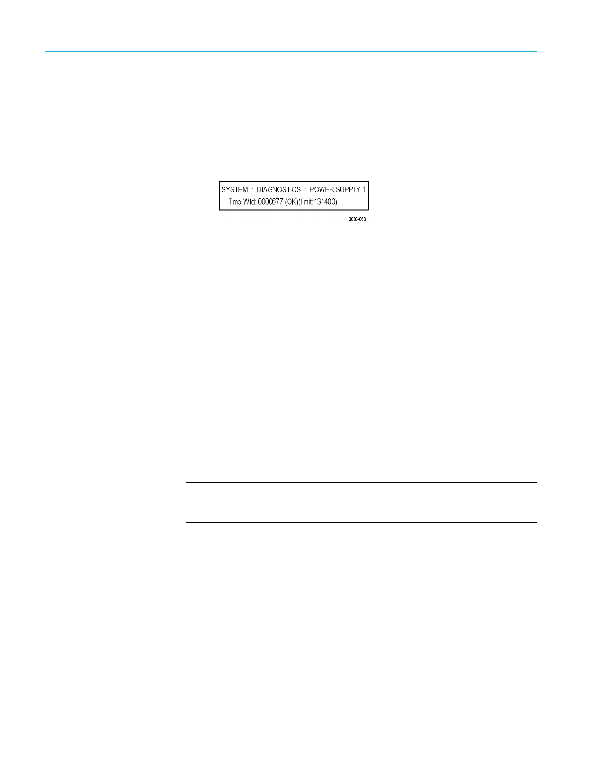
How to operate an instrument with two power supplies (Option DPW only)
c. Press the up (▲)
DIAGNOSTICS : POWER SUPPLY 1. The second line of the display
will list the number of hours the supply has been the active supply and the
backup supply.
d. Press the right (►) arrow button to display the number of temperature
weighted hours of the first supply as shown below. Note the number of
hours of hours shown.
e. Press the up (▲)ordown(▼) arrow button to select SYSTEM :
DIAGNOSTICS : POWER SUPPLY 2.
f. Press the right (►) arrow button to display the number temperature
weighted hours of the second supply. Note the number of hours of hours
shown.
3. If the Power Supply module with the greatest number of temperature weighted
hours i
Otherwise, you do not need to change the preferred supply configuration.
4. If you
button to access the SYSTEM menu.
s not the currently the preferred supply, then continue this procedure.
want to change the preferred supply configuration, press the SYSTEM
or down (▼) arrow button to select SYSTEM :
5. Pres
6. Pre
NOTE. When viewed from the front of the instrument, Power Supply 1 is the left
Power Supply module and Power Supply 2 is the right Power Supply module. This
m
7. If status of the supply is Inactive, press the ENTER button to change the
stheup(▲)ordown(▼)arrowbuttontoselectSYSTEM : POWER
SUPPLY PREFERRED SELECT.
ss the left (◄)orright(►) arrow button to display the supply you want
to be the primary (active) supply: Power Supply 1 or Power Supply 2. The
second line of the display shows the supply status: Active, Preferred or
Inactive.
atches the orientation of the PWR1 and PWR2 indicators on the front panel.
status to Active, Preferred. The front-panel indicator for the selected supply
should change to bright green.
34 SPG700 User Manual
Page 55

How to operate an instrument with two power supplies (Option DPW only)
To hot-swap a P
ower Supply module
This procedure describes how to replace a Power Supply module while the
instrument is in operation. Perform the following steps to hot-swap a Power
Supply modul
WAR NI NG . Disconnect the power cord from the Power Supply module before you
remove the module from the instrument. Also, do not connect a power cord to the
Power Supply module while the module is not installed in the instrument. There
are dangerous high voltages inside the module when the power cord is connected.
CAUTION. To prevent an unexpec ted shutdown of the instrument, be sure to
unplug the correct power cord if you are replacing a faulty Power Supply module.
(See Figure 7.)
When viewed from the front of the instrument, Power Supply 1 is the left Power
Supply module and Power Supply 2 is the right Power Supply module. This
matche
The STATUS LED on the rear panel of each Power Supply module will match the
status shown by the front-panel PWR1 and PWR 2 indicators.
1. Remove the power cable from the Power Supply module that you are
s the orientation of the PWR1 and PWR2 indicators on the front panel.
removing or replacing.
e:
2. Pull out the handle located at the bottom of the supply. (See Figure 7.)
3. Whi
4. In
5. If necessary, push the handle of the s upply into the storage position.
6. Connect the power cable to the Power Supply module you installed.
7. Check that the status of the Power Supply module you just installed is bright
8. If desired, change the preferred supply configuration. (See page 33, To
NOTE. It is recommended that you configure the supply with the most temperature
weighted hours to be used as the primary preferred supply. This allows for the
newer supply to be preserved so it can provide the best possible backup should
the primary supply fail.
le pushing the retaining latch to the left, use the handle to pull the Power
Supply module out of the instrument.
sert the replacement supply into the instrument until it latches into place.
or dim green.
configure the preferred (active) supply.)
SPG700 User Manual 35
Page 56

How to operate an instrument with two power supplies (Option DPW only)
Figure 7: Removing a Power Supply module
36 SPG700 User Manual
Page 57

How to use Stay Genlock
®
How to use Stay
About Stay Genlock
To enable Stay Genlock
®
Genlock
Stay GenLoc
additional robustness and stability for genlocked Sync Pulse Generators (SPGs),
as in a master/slave configuration.
If the external reference is removed from the genlock input, the instrument
must use the internal oscillator as a frequency reference. Although the OXCO
is a precision component, small frequency differences are inevitable. However,
the Stay GenLock
therefore attempts to hold the last stable frequency before genlock was lost.
See the Video Sync Pulse Generator and Electronic Changeover Unit System
Integration Technical Reference manual for more information about the Stay
®
Genloc
To ena
steps:
k
®
ble the Stay GenLock
®
®
k
is a digital genlock technology developed by Tektronix to provide
®
technology maintains a history of the clock frequency, and
function.
®
function on the instrument, perform the following
NOTE. The following procedures use the front panel controls on the instrument
®
to enable Stay GenLock
Interface to enable Stay GenLock
1. Press the front-panel REFERENCE button to access the REFERENCE menu.
2. Use the up (▲)ordown(▼) arrow button to display REFERENCE : LOCK
LOSS ACTION.
3. Use the left (◄)orright(►) arrow button to display Stay at Current
Frequency, and then press the ENTER button to confirm the selection.
. You can also use the Reference menu in SPG700 Web
®
.(Seepage55,Referencemenu.)
SPG700 User Manual 37
Page 58

How to use Stay Genlock
®
38 SPG700 User Manual
Page 59

AES menu
Use the AES button menu to view and configure the timing offset of the Word
Clock (48 kHz) and DARS outputs and to set the signal level of the Word Clock
output.
NOTE. In the current software release, the SPG700 Web Interface does not
support the AES menu. Use the AES button on the front panel to access the menu
selections desc ribed below.
Menu diagram
The following figure s hows the main menu diagram for the AES button.
Figure 8: AES button menu diagram
SPG700 User Manual 39
Page 60

AES menu
AUDIO-VIDEO SYNC
TIMING OF
AES WOR
FSET
DCLOCK
OUTPUT
This menu item s
Clock and DARS signal outputs. Use the left (◄)orright(►) arrow button
to make the selection.
The selection items are Free Run, Frame Reset 1 (2.997 Hz),
Frame Reset 2 (6.250 Hz),andFrame Reset 3 (3.000 H z). For Free Run, the
Wo rd Clock and DARS signals are not synchronized with any of the frame reset
signals. Press the ENTER button to enable the selection.
NOTE. If the frame reset signal used by the Word Clock and DARS signals is
reset by a c
is also reset.
Press the ENTER buttontoaccesstheAES TIMING OFFSET submenu. Use
this submenu to set the timing offset of the Word Clock a nd DARS outputs
relative to the genlock signal or the internal reference signal.(See page 40.)
Sets the signal level of the Word C lock output. Use the left (◄)orright(►)
arrow button to select 1Volt(AC)or 5Volt(DC).PresstheENTER button
to enable the selection.
elects the frame reset signal that is synchronized with the Word
hange of the video format, the Word Clock and DARS signal timing
AES TIMING OFFSET submenu
The following menu opens when you press ENTER in the AES button menu with
ING OFFSET selected. (See Figure 8 on page 39.)
TIM
Figure 9: AES TIMING OFFSET submenu diagram
Use the left (◄)orright(►) arrow button to change the timing offset value
in 1 μs steps. Set the value from –160 ms to +160 ms. A minus value is set as
Advance and a plus value is set as Delay.
NOTE. You can reset the timing offset to zero by pressing the left ( ◄)
and right (►) arrow buttons simultaneously.
You cannot adjust the timing offset when Free Run is selected as the
AUDIO-VIDEO SYNC mode. (See page 39, AES menu.)
40 SPG700 User Manual
Page 61

AES menu
AES menu facto
ry default settings
The following table shows the settings for the AES button menu that are reset
when you use the PRESET submenu to recall the factory default settings. (See
page 112, Preset
Table 3: AES button menu factory default settings
Menu item name Settings
AUDIO-VIDEO SYNC
TIMING OFFSET (Delay or Advance)
AES WORD CLOCK OUTPUT 1 Volt (AC)
s submenu.)
Free Run
0.0 μsec
SPG700 User Manual 41
Page 62

AES menu
42 SPG700 User Manual
Page 63

Black menu
UsetheBlackmenutoviewandconfigure the Black outputs. Click one of the
bars for the three Black outputs (1, 2, or 3) to open the configuration submenu for
that output. The bars for each Black output lists the current signal being output
(i.e. NTSC Black Burst).
The following figure shows the Black menu with the Black 2 submenu expanded.
Most of the entries in all three submenus are the same with the differences noted
below.
Figure 10: Black menu with the Black 2 submenu expanded
NOTE. Black outputs 1–3 are a group that use the same HD tri-level sync rate.
When the instrument is in Factory mode, a Calibration menu option is available.
See the SPG700 Service Manual for more information.
SPG700 User Manual 43
Page 64

Black menu
Black Output s
ettings
Format
This submenu contains the Format and Field Reference selections.
Use drop-down list to select the signal format for the selected Black output.
Not all of the formats are available for the Black outputs; the available format
choices depend on the following:
The CW 10 M Hz format appears only for the Black 3 output. When CW
10 MHz is the selected output format, other Black menu items are unavailable
for the Black 3 output.
The available HD output formats depend on whether the HD tri-level sync rate
for the selected Black output is set to integer or non-integer. (See Table 4.)
Table 4: Black output formats
teger formats
Non-in
NTSC NTSC
PAL PAL
NTSC-J NTSC-J
CW 10 MHz
1080 59.94i 1080 60i
1080
1080 29.97p 1080 24sF
1080 23.98p 1080 30p
0 59.94p
108
1080 47.95p 1080 24p
720 59.94p 1080 60p
1 PPS
1
The CW 10 MHz format selection appears only for the Black 3 output.
1
23.98sF
rformats
Intege
CW 10 MHz
50i
1080
0 25p
108
80 50p
10
080 48p
1
720 60p
720 50p
1 PPS
1
Field Reference
This menu item is available only for non-HD formats. Use the drop-down list to
select Enable or Disable for the field reference on the selected Black output.
44 SPG700 User Manual
Page 65

Black Timing settings
Black menu
Use these settings to adjust the timing offset of the selected Black output relative
to the internal reference signal. The range of the timing adjustment depends on
the format of the selected Black output.
Vertical Delay
Horizontal Delay
Enter the Vertical Delay in 1 line increments for the selected Black output.
Enter the Horizontal Delay in increments based on the format of the selected
Black output.
NOTE. If you are using the 50, 59.94 or 60 Hz progressive sync as a genlock
source, as well as LTC as a time-code source, there are two possible alignments
for the resulting system. Alignment can be checked by looking at the LTC timing
status screen. If the timing is near zero, then it is aligned. If the timing is near a
frame of offset, then it is not aligned.
You will need to unlock and re-lock the reference to achieve the desired alignment
if this is important to the application you are using. Alternatively, you can use a
lower frame rate video reference like NTSC, PAL, or 1080i tri-level.
The following table shows the Vertical Delay line settings and Horizontal Delay
adjustment ranges.
Table 5: Black output timing adjustment ranges
Format nam e Line settings Coarse settings (μs) Fine settings (ns)
NTSC
PAL ± 1250 ± 64.0000 ± 10.00
1080 60i ± 562 ± 29.6296 ± 10.00
1080 59.94i ± 562 ± 29.6593 ± 10.00
1080 50i ± 562 ± 35.5556 ± 10.00
1080 24sF ± 562 ± 37.0370 ± 10.00
1080 23.98sF ± 562 ± 37.0741 ± 10.00
1080 30p ± 562 ± 29.6296 ± 10.00
1080 29.97p ± 562 ± 29.6593 ± 10.00
1080 25p ± 562 ± 35.5556 ± 10.00
1080 24p ± 562 ± 37.0370 ± 10.00
1080 23.98p ± 562 ± 37.0741 ± 10.00
720 60p ± 375 ± 22.2222 ± 10.00
720 59.94p ± 375 ± 22.2444 ± 10.00
720 50p ± 375 ± 26.6667 ± 10.00
± 525 ± 63.5556 ± 10.00
SPG700 User Manual 45
Page 66

Black menu
Black Timecode settings
NOTE. The Black Timecode settings are available only when a non-HD format is
set as the sign
al format of the selected Black output.
Source
Offset
Use the drop-down list to select the timecode source. The default value is Disable.
Disable. Disables the timecode function for the selected Black output.
Local (DST). Uses the local time of day with Daylight Savings Time offset
as the timecode.
Local (No DST). Uses the local time of day without Daylight Savings Time
offset as the timecode.
UTC. Uses Coordinated Universal Time as the timecode.
Program Time. Uses the program time counter as the timecode.
NOTE. For the Black and LTC outputs, setting the timecode source to Local (DST),
Local (No DST), or UTC will cause the ST309 output DST and time zone data to
be set to match the selec tions.
In addition to enabling the timecode source, at least one line must be specified
and enabled to carry a VITC signal.
Enter an offset for the selected Black output, relative to the selected timecode
source in the format ±HH:MM:SS:FF. You can enter a time offset of up to
:59:59:29 (maximum frame value depends on the frame rate of the video
±23
signal).
NOTE. The Offset adjustment allows you to enter a time zone correction of up to
±23:59 hours. However, the S T309 standard only implements codes for time zones
in the range of -12 to +13 hours. Therefore, when you are using ST309 data as the
Time of Day source, it is recommended that the combined programmed offset from
time zone and daylight savings time be restricted to the range of -12 to +13 hours.
Enable 30 Drop-Frame
46 SPG700 User Manual
Use the check box to enable or disable the 30 Drop Frame mode. Most
applications will prefer drop-frame compensation VITC on NTSC, but if needed,
it can be disabled by this menu item. This menu item appears only when NTSC or
NTSC-J is set as the signal format for the selected Black output.
Page 67

Black menu
VITC 1 and 2 Line
selections
Use these menu i
interval.
Enter the vide
can select lines from line 10 to 20 (lines 14 and 16 are recommended). For PAL,
you can select lines between 6 and 22 (lines 19 and 21 are recommended).
Select the Enable check box for the selected line to enable or disable the output
of a VITC signal.
tems to insert the same VITC signal on 1 or 2 lines of the vertical
o line number to insert the selected VITC signal. For NTSC, you
Blank On Reference Unlock settings
These settings are available only for the Black 2 output. Use the Enable check
box to ena
signal is detected. When enabled, the Black 2 output will be blanked for as long
as the loss of lock condition occurs. The purpose of this function is to trigger a
downstream change-over unit.
NOTE. When the Black 2 output is configured to blank on the loss of reference
lock, the output should not be used for normal reference applications.
ble or disable the b lanking function when a loss of lock to the reference
Delay
When the Blank on Reference Unlock function is enabled, you can set the amount
of time delay before the Black 2 output will be blanked when a loss of lock to the
rence signal is detected. The purpose of the delay is to reduce false alarms by
refe
allowing a set amount of time for the loss of lock condition to clear before the
Black 2 output is blanked. Enter the delay in HH:MM:SS.
Black 1-3 HD Tri-level Sync setting
Use this setting to set the HD tri-level sync rate for the three Black outputs. The
HD tri-level sync rate setting limits which signal formats are available for the
Black outputs. The Black outputs 1–3 are a group that must use the same HD
tri-level sync rate (integer or non-integer).
Use the drop-down list to select either Non-Integer (59.94, 47.95, 29.97, 23.98)
orInteger (60, 50, 48, 30, 25, 24).
SPG700 User Manual 47
Page 68

Black menu
Black menu fac
tory default settings
The following table shows the settings for the Black menu that are reset when
you use the Preset submenu to recall the factory default settings. (See page 112,
Presets subm
Table 6: Black button menu factory default settings
Menu item name Settings
Format
Field R eference
Timing
Timecode
Blank On Reference Unlock
Blank On Reference Unlock Delay
Black 1–3: HD Tri-Level Sync
1
These settings appear only for non-HD formats.
2
This setting appears only when the format is set to NTSC.
3
These settings appear only for the Black 2 output.
enu.)
1
1
NTSC
Disable
Vertical: 0 Line(s)
Horizontal Coarse: 0.0 μsec
Source: Disable
Offset: +00:00:00:00
VITC 1 Line
Line Number:
NTSC/NTSC-J: 14
PAL: 19
Output: Disable
VITC 2 Line
Line Number:
NTSC/NTSC-J: 16
PAL: 21
Output: Disable
Enable 30 Drop Frame: Disabled
3
3
Disabled
00:00:10
2
Non-integer
48 SPG700 User Manual
Page 69

Embedded menu (Option SDI only)
When Option SDI is installed, use the Embedded menu to view and configure the
embedded audio settings on the SDI video outputs. Use this menu to select the
audio group f
group parameters.
or subsequent audio channel configuration,andtoconfigure audio
You c a n s e l e
For 3G Level B formats, you can select audio group 1, 2, 3, or 4 for both Link A
and Link B.
In each audio group you can do the following:
Enable or
Select a specific channel
Set the sampling mode
Set the embedded audio frequency
Set the embedded audio amplitude
Set the click rate for the selected channel
Click
Embedded 2 shows the selections for the SDI 2 outputs.
ct audio group 1, 2, 3, or 4 for all SD, HD, and 3G Level A formats.
disable the embedded audio
Embedded 1 to show the selections for the SDI 1 outputs; clicking
SPG700 User Manual 49
Page 70

Embedded menu (Option SDI only)
The following fi
You may have to scroll down the window to see the Secondary Output selection.
NOTE. The SPG700 Web Interface has an issue where the column headings in the
Embedded menu do not align with their associated columns. The following figure
shows the proper alignment of the column headings.
gure shows a partial menu diagram for the Embedded 1 menu.
Figure 11: Partial Embedded menu diagram
50 SPG700 User Manual
Page 71

Embedded menu (Option SDI only)
Group enable
Sampling
Channel
Mode
Frequency
For most SDI sig
enabling the check box next to the Link A, Group selection. When the SDI
signal format is set to 3G Level B, you can select between Link A and Link B
for each audio group.
For each audio group, use the drop-down list to set the sampling alignment status
bits for the selected audio group's Audio Control Packet (ACP). Select Frame,
Frame w/o Frame #,orAsynchronous. The sampling alignment status bits
apply equally to each channel within the selected audio group.
Channels are listed in vertical columns within each audio group. Each channel has
its own settings.
Use the drop-down list for each channel to select the mode: Active, Inac tive,
and Mute.
For eac
to 20 kHz, in steps of 0.5 Hz.
h channel, enter the frequency of the embedded audio signal from 10.0 Hz
nal formats, select the desired Link A audio group (1–4) by
Amplitude
Audio Click
igin
Or
Secondary Output
For each channel, enter the audio amplitude from –60 dBFS to 0 dBFS, in steps of
S.
1dBF
For each channel, use the drop-down list to set the audio click rate to one click
every one, two, three, or four seconds, or turn the click off.
For each channel, click in the Origin box to enter a channel origin ID of up to
four ASCII characters. The default origin values are based on the link, group
and channel numbers. For example, an origin value of A1-1 represents Link A,
roup 1 and channel 1.
g
Use the drop-down list at the bottom of the Embedded menu to select one of the
following signals for the secondary (bottom) BNC connector of the selected SDI
output: Tones , No Audio,orMute Audio.
The SDI 1B audio output is the same format and sample structure as the SDI 1A
audio output. The same is true for the SDI 2 connectors.
SPG700 User Manual 51
Page 72

Embedded menu (Option SDI only)
Embedded menu
factory default settings
The following table shows the settings for the Embedded menu that are reset
when you use the Preset submenu to recall the factory default settings. (See
page 112, Preset
Table 7: Embedded menu factory default settings
Menu item name Settings
Embedded 1 or
Embedded 2
Group 1–4 (Link A)
Group 1–4 (Link B)
Sampling
Channel 1–4
Secondary Output
1
k B, Group 1–4 settings are available only when the SDI output mode is set to 3G-Level B. (See page 59,
The Lin
SDI menu (Option SDI only).)
s submenu.)
Disable
1
Disable
Frame
Mode: Active
Frequency: 1000.0 Hz
Amplitude: –20 dBFS
Audio Click: None
Channel Origin: A1-1 through A4-4
Tones
52 SPG700 User Manual
Page 73

LTC menu
UsetheLTCmenutoviewandconfigure the LTC inputs and outputs on the
GPI/LTC port. The following figure shows the LTC menu with the LTC
1 submenu exp
Figure 12: LTC menu with LTC 1 selected
anded to show the menu selections.
UseasI
Source
nput
This menu item is available only with LTC 1. Select this check box to force LTC
1tobeaninput.
Use drop-down list to select one of the following LTC signal sources. The default
value is Local (DST).
Disable. Disables the LTC outputs.
Local (DST). Uses the local time of day with Daylight Savings Time offset
as the timecode.
Local (No DST). Uses the local time of day without Daylight Savings Time
offset as the timecode.
UTC. Uses Coordinated Universal Time as the timecode.
rogram Time. Uses the Program Time counter as the timecode.
P
NOTE. For the Black and LTC outputs, setting the timecode source to Local (DST),
Local (No DST), or UTC will cause the ST309 output DST and time zone data to
be set to match the selections.
SPG700 User Manual 53
Page 74

LTC me n u
Offset
Type
Level
Enter the LTC Of
fset in the form of ±HH:MM:SS:FF.
NOTE. The Offset adjustment allows you to enter a time zone correction of up to
±23:59 hours. However, the S T309 standard only implements codes for time zones
in the range of -12 to +13 hours. Therefore, when you are using ST309 data
as the Time of Day source, it is recommended that the combined programmed
offset from time zone and the daylight saving time be restricted to the range of
-12 to +13 ho
urs.
Use the drop-down list to select one of the following LTC output signal formats:
Table 8: LTC output signal formats
Format Rate Delay range
24fps 24 fps at 24 Hz
25fps 25 fps at 25 Hz
30fps 30 fps at 30 Hz
30fps drop-frame 30 fps drop frame at 29.97 Hz
24fps @ 23.98 Hz 24 fps at 23.98 Hz
±20.83 ms
±20.00 ms
±16.67 ms
±16.68 ms
±20.85 ms
Enter the signal level of the selected LTC output between 0.5 V and 5.0 V in
0.5 V steps.
Delay
Enter the delay in milliseconds that will be used for all the signal formats.
LTC menu factory default settings
The following table shows the settings for the LTC menu that are reset when
you use the Preset submenu to recall the factory default settings. (See page 112,
Presets submenu.)
Table 9: LTC button menu factory default settings
Menu item name Settings
LTC 1 to LTC 4
Use as Input
(LTC 1 only)
Source Local (DST)
Offset
Type
Level 2.0 V
Delay 0.00 msec
Not selected
+ 00:00:00:00
30 fps drop frame
54 SPG700 User Manual
Page 75

Reference menu
Use the Reference menu to view the current status of instrument settings such as
the signal reference source, the signals being output, and information about system
faults and al
Reference information and the Genlock Timing information.
Figure 13: Reference tab menu
erts. The following figure shows the Reference menu including the
Reference settings
Source
Use the drop-down menu to select the reference source for the module timing.
ollowing selections are available:
The f
Internal. Uses the internal clock frequency setting as the timing reference.
NTSC Burst. Uses the NTSC Black burst signal applied to the REF input
connector on the rear panel as the timing reference.
NTSC Burst with 10 Field ID. Uses the NTSC Black burst with 10 Field ID
signal applied to the REF input connector as the timing reference.
PAL Burs t. Uses the PAL Black burst signal applied to the REF input
connector as the timing reference.
HD Tri-Level Sync. Uses the HDTV trilevel signal applied to the REF input
connector as the timing reference.
CW. Uses the 1, 3.58, 4.43, 5, or 10 MHz continuous wave signal applied to
the REF input connector as the timing reference.
SPG700 User Manual 55
Page 76

Reference menu
Loss of Lock Action
This menu item i
drop-down list to select the action that the module will make when a loss of lock
condition is detected. Select one of the following actions:
Genlock Timing settings
The Genlock Timing settings adjust the timing offset of the input signal relative to
the internal reference signal. The selections are unava ilable when the reference
source is set to Internal.
The range of the timing adjustment depends on the selected signal format. (See
Table 10. )
s not active when the reference source is set to Internal. Use the
Stay at Current Frequency. Sets the module timing to keep operating at the
current frequency until the reference signal is recovered.
Use Internal Frequency. Sets the module timing to switch to the internal
frequency setting until the r eference signal is recovered.
Vertical Delay. Enter the delay to adjust the Genlock vertical offset in 1
line increments.
Horizontal Delay. Enter the Genlock horizontal offset.
NOTE. If you are using the 50, 59.94 or 60 H z progressive sync as a genlock
source, as well as LTC as a time-code source, there are two possible alignments
for the resulting system. Alignment can be checked by looking at the LTC timing
status screen. If the timing is near zero, then it is aligned. If the timing is near a
frame of offset, then it is not aligned.
You will need to unlock and re-lock the reference to achieve the desired alignment
if this is important to the application you are using. Alternatively, you can use a
lower frame rate video reference like NTSC, PAL, or 1080i tri-level.
Table 10: Timing adjustment ranges for reference input signals
Format name Line settings Coarse settings (μs) Fine settings (ns)
NTSC
PAL ± 1250 ± 64.0000 ± 10.00
1080 60i ± 562 ± 29.6296 ± 10.00
1080 59.94i ± 562 ± 29.6593 ± 10.00
1080 50i ± 562 ± 35.5556 ± 10.00
1080 24sF ± 562 ± 37.0370 ± 10.00
1080 23.98sF ± 562 ± 37.0741 ± 10.00
1080 30p ± 562 ± 29.6296 ± 10.00
1080 29.97p ± 562 ± 29.6593 ± 10.00
± 525 ± 63.5556 ± 10.00
56 SPG700 User Manual
Page 77

Table 10: Timing adjustment ranges for reference input signals (cont.)
Format nam e Line settings Coarse settings (μs) Fine settings (ns)
1080 25p ± 562 ± 35.5556 ± 10.00
1080 24p ± 562 ± 37.0370 ± 10.00
1080 23.98p ± 562 ± 37.0741 ± 10.00
720 60p ± 375 ± 22.2222 ± 10.00
720 59.94p ± 375 ± 22.2444 ± 10.00
720 50p ± 375 ± 26.6667 ± 10.00
Reference menu factory default settings
The following table shows the settings for the Reference menu that are reset when
you use the Preset submenu to recall the factory default settings. (See page 112,
Presets submenu.)
Table 11: REF button menu factory default settings
Reference menu
tem name
Menu i
ence
Refer
ce
Sour
ock Timing
Genl
Loss of Lock Action
1
These menu items are not active when the reference source is set to Internal.
1
1
ngs
Setti
Internal
ical: 0.0 Line(s)
Vert
Horizontal 0.0 μs
Stay at current frequency
SPG700 User Manual 57
Page 78

Reference menu
58 SPG700 User Manual
Page 79

SDI menu (Option SDI only)
Option SDI provides two independent HD-SDI test signal generators; use the SDI
menu to view and c onfigure the signals on the SDI video outputs. Select either
SDI 1 or SDI 2 t
The menu selections are similar, but independent for each output. The following
figure shows the SDI menu with the SDI 1 submenu expanded.
o expand the selections to show the menus for each generator.
Figure 14: SDI menu with the SDI 1 submenu expanded
SPG700 User Manual 59
Page 80

SDImenu(OptionSDIonly)
SDISignalsub
menu
The Signal submenu contains the Standard, Signal Selection, Timing, and other
information for defining the SDI signal. The following figure shows an example
of the Signal
submenu.
Signal Standard settings
Figure
These settings contains the selections for the Output mode, Format, and Sample
Stru
NOTE. You can read more about selecting and generating an SDI output signal.
(See page 85, How to select an SDI output signal.)
15: SDI Signal submenu
cture/Depth.
Output Mode. Use the drop-down list to select the Output Mode or to set the
SDI serial link multiplexing method to Level A or Level B.
3G-
SD. Provides a SMPTE 259 compliant signal that runs at 270 Mbps.
D (1920 × 1080). Provides a 1080-line, SMPTE 274M compliant signal.
H
HD (1280 × 720). Provides a 720-line, SMPTE 296M compliant signal.
60 SPG700 User Manual
Page 81

SDI menu (Option SDI only)
3G-Level A.Thi
as described in SMPTE 425. For the mapping structure 1 signals such as
1080p50, 1080p59.94 and 1080p60, a Level A stream looks similar to HD
video (as defined in SMPTE 292), except the data rate is twice as fast. In
Level A, the lines are sent in order, consecutively. For other mapping
structures, the video is at a lower frame rate, but has more bits and/or
includes mo
on the Level A mapping method.
The follow
(1920 x 1080). The output is a 1080-line, SMPTE 425 compliant
signal.
(1280 x 720). The output is a 720-line, SMPTE 425 compliant signal.
(2k x 1080). This output provides 2048 × 1080 resolution signals,
primarily for digital cinema applications.
3G Level B. This is an alternate way of constructing the 3 Gb/s serial data
stream, as described in SMPTE 425. A Level B stream looks similar to
ink (as defined in SMPTE 372M). The serial data is constructed by
dual l
interleaving the two links of the dual link video signal. As a result, some
formats will have the serial data take two lines worth of time to propagate.
This has implications for the effects of the pathological signals, and can
confuse the definition of timing adjustments. Refer to the SMPTE 372M
and SMPTE 425 standards for more information.
s is one way of constructing the 3 Gb/s serial data stream,
re channels. Re fer to the SMPTE 425 standard for details
ing 3G Level A signals are available:
The following 3G Level B signals are available:
(1920 x 1080). The output is a 1080-line, SMPTE 425 compliant
signal.
(2k x 1080). This output provides 2048 × 1080 resolution signals,
primarily for digital cinema applications.
(2xHD 1080).This output provides two standard 1080-line SMPTE
292 HD streams in the same format. Select between Test Signal/Test
Signal or Test Signal/Black for the two streams.
(2xHD 720). This output provides two standard 720-line SMPTE
292 HD streams in the same format. Select between Test Signal/Test
Signal or Test Signal/Black for the two streams.
Format. Use the drop-down list to select the signal format for the selected
SDI output. The available format choices depend on the selected Output
Mode selection. (See page 86, Available SDI output signals.)
SPG700 User Manual 61
Page 82

SDImenu(OptionSDIonly)
Signal Selection setting
Sample Structu
re/Depth. When the output mode is set to a
non-fast-progressive format, the Sample Structure/Depth menu is available.
There are several sample structures to choose from. Use the drop-down list to
select the desired sample structure.
3G Level A / Level B formats (720 line)
GBR 444 10b YCbCr 444 10b
GBRA 4444 10b YCbCrA 4444 10b
2K line formats
XYZ 444 12b
GBR 444 12b
NOTE. For SD, HD, and 3G fast-progressive formats, the color space / sample
structure / depth is always YCbCr 422 10 bit.
Use this setting to access test signal sets when the module is in generator mode.
The instrument is shipped with a standard set of test signals already installed.
able 24 on page 88.) You can also download enhanced test signals. (See
(See T
Table 25 on page 93.)
Signal Timing settings
hese settings to adjust the timing offset of the serial digital video outputs
Use t
relative to the internal reference signal (frame reset signal). This allows you
to adjust the timing of this module relative to another module or to an external
reference (such as Genlock).
Vertical. Enter the vertical timing offset; you can set the value from –½ to +½
frame in 1-line steps.
NOTE. A “line" of timing refers to the timing as if it were a raster scanning a
CRT.Thismaynotbethesameasthetimethatalineofdataispresentonthe
erial link because of the way that Level B signals are interleaved.
s
Horizontal. Enter the horizontal timing offset ; you can set the value from –1
to +1 line in 1-clock steps.
Relative To. Sets the Zero Timing D-to-A compensation factor on or off
for HD (1.485 Gb/s) and SD (270 Mb/s) formats only. Use the drop-down
list to set the timing relative to Serial(0H)orAnalog(DAC).Intheserial
mode (default), the output timing does not include compensation for the delay
through a nominal D-to-A converter.
62 SPG700 User Manual
Page 83

SDI menu (Option SDI only)
Other Signal submenu
settings
The following s
SMPTE 352 Payload ID Enable. Select the check box to enable the SMPTE
352M Payload I
NOTE. The SMPTE 352M payload identifier is a required element for a compliant
3 Gb/s signal stream. The payload identifier is optional for SD and HD formats.
Secondary Output. Use the drop-down list to select a Test Pattern or a
Black signal for the secondary BNC connector.
When set to the Test Pattern selection for channel 1, the SDI 1A and SDI 1B
connectors will output the same test signal. The same is true for the channel 2
connectors when Test Pattern is set as the Secondary Output selection for
channel 2.
When set to the Black selection for channel 1, the SDI 1B Black signal is
the same format and sample structure as the SDI 1A output. The same is
true for the channel 2 connectors when Black is set as the Secondary Output
select
Alpha Channel Data. This setting is active only when the sample structure is
set to
channel when a sample structure that includes an alpha channel is selected.
The channel can contain a duplicate of the Y or G channel data or a flat field
signal. Use the drop-down list to Copy of Y/G Channel or select a 0% to
100% Flat Field in 10% increments.
ettings appear near the bottom of the SDI Signal submenu:
dentifier.
ion for channel 2.
“+A” for 3G signal formats. Selects the data to be placed on the alpha
2xHD Stream Content. This setting is active only when the signal format is
set to 2×HD. It selects the content for the first and second HD signals on link
A and link B. Use the drop-down list to select Test Signal/Test Signal, Te s t
gnal/Black,orBlack/Test Signal.
Si
SPG700 User Manual 63
Page 84

SDImenu(OptionSDIonly)
SDI Configure Z
Zone plate parameters
settings
oneplate submenu
Use this submenu to configure the parameters of zone plate signals. These settings
become active when you select a zone plate signal for output from the Signal
Selection dr
individual zone plate signal.
The Configure Zoneplate submenu consists of three major sections: Zoneplate
Parameters, Video, and information that applies to all zone plate signals. For
more information on using zone plate signals, refer to the information later in this
document. (See page 95, SDI Zone plate signals.)
The following figure shows an example of the zone plate parameters for a circle
zone plate.
op-down list. The information for each signal varies depending on the
Figure 16: Circle zone plate configuration parameters
The information for the zone plate parameters varies with the zone plate signals.
The parameters are discussed i n more detail later in this document.
Frequency. This menu item is dependent on the zone plate signal. Detailed
information for the different zone plate signals is provided in a separate table.
(SeeTable26onpage99.)
The remaining parameters are zone plate dependent parameters. These
are discussed in detail later in this document. (See page 100, Zone plate
dependent parameters.)
64 SPG700 User Manual
Page 85

SDI menu (Option SDI only)
Video settings
The following fi
submenu.
Figure 17: C
There are t
the related check box.
Y/G/X Ena
components: the Y component for a YCbCr sample structure, the G
component for a GBR sample structure, or the X component for an XYZ
sample structure.
Cb/B/Y Enable. Select the check box to display one of the three signal
components: the Cb component for a YCbCr sample structure, the B
component for a GBR sample structure, or the Y component for an XYZ
sample structure.
Cr/R/Z Enable. Select the check box to display one of the three signal
components: the Cr component for a YCbCr sample structure, the R
comp
sample structure.
gure shows the Video menu selections for the Configure Zoneplate
onfigure Zoneplate video menu selections
hree video parameters that can be enabled or disabled by selecting
ble. Select the check box to display one of the three signal
onent for a GBR sample structure, or the Z component for an XYZ
NOTE. When the sampling structure for the current format uses the YCbCr color
space, the default settings enable only the Y channel. This results in the familiar
Black to white zone plate patterns. When the RGB color space is used the default
settings enable all three channels, also resulting in the Black to white zone plate
tterns.
pa
A colored zone plate pattern can be created by enabling or disabling individual
hannels. When the XYZ color space is used, the resultant patterns will show
c
some chroma in all combinations of the X/Y/Z channel settings, due to the inherent
encoding of this color space.
SPG700 User Manual 65
Page 86

SDImenu(OptionSDIonly)
Other parameter settings
The following fi
gure shows other menu selections for the Configure Zoneplate
submenu These menu selections apply to all of the zone plate selections.
Figure 18: Configure Zoneplate parameters for all zone plate signals
Enable T Reset. Use the Enable T Reset parameter to reset the time
coordinate (t in the zone plate equation) of the pattern to zero. When T Reset
is first enabled, the time coordinate is reset to zero and there is no apparent
motion in the zone plate, even if any of the time coefficients (K
2
or K
e non-zero. Enabling the T Reset parameter does not set the other
)ar
T
XT,KYT,KT
parameters to zero.
If you th
en change any of the K parameters, the temporal (t) coordinate will be
allowed to change to match. Subsequent changes to K parameters will first
reset the time coordinate (t), and then allow it to change with the K parameter.
When the Enable T Reset check box is cleared, the zone plate time coordinate
will increment continuously. Resetting all of the time coefficients (K
K
,andK
T
2
) to zero will stop the apparent zone plate motion but the temporal
T
coordinate will remain where it is, even if it has moved to an off-screen
position.
XT,KYT
,
,
You must enable the T Reset parameter to reset the temporal coordinate to
zero. To completely d isable all motion and reset the pattern, set all of the time
ated K parameters to zero and enable the T Reset parameter by selecting
rel
the check box.
veform. Use this parameter to set the waveform shape. Use the drop-down
Wa
list to set the waveform to a Sine, Triangle, or Square wave.
ave As. Use this parameter to save the setups in one of the custom files.
S
Select the custom file from the drop-down list.
66 SPG700 User Manual
Page 87

SDI menu (Option SDI only)
SDI Moving Pic
ture submenu
Use this submenu to scroll the active picture area of the serial digital video signal
up/down or left/right (or randomly), when in generator mode. The following
figure shows t
Figure 19: SDI Moving Picture submenu
NOTE. The Moving Picture function is not available with zone plate or multiburst
signals. However, zone plate signals can be defined with motion in the zone plate
parame
The Moving Picture function is enabled whenever the H Step or V Step parameter
to a value other than 0.
is set
he Moving Picture submenu.
ters. (See page 97, To modify a zone plate signal.)
When Moving Picture is enabled, the circle and text overlays remain static
rdless of the signal type (standard test signal or “frame (.BMP) picture”).
rega
However, the logo overlay remains static for only standard test signals, but
continues to move when used with a “frame (.BMP) picture.”
Use the following menu items to specify the Moving Picture setups:
ndom. Select this check box to enable random scrolling. Clear the check
Ra
box to disable random scrolling.
orizontal Step. Enter the number of pixels to be scrolled per frame set in the
H
Period menu item below. Set the value from –252 to +252 in 4-sample steps.
ertical Step. Enter the number of lines to be scrolled per frame set in the
V
Period menu item below. Set the value from–252to+252in1-linesteps.
Period. Enter the time interval between occurrences of the scrolling. Set the
value from 1 to 16 in 1-frame steps.
SPG700 User Manual 67
Page 88

SDImenu(OptionSDIonly)
SDI Video subm
enu
Use this submenu to modify the video output signal. You can enable or disable
individual video components, enable or disable edge filtering on each video
line, enable
(SD formats only), and enable or display the AV Timing mode.
The followi
NOTE. The items in this menu modify the signal output to m ake it non-standard.
To indicate that the signal is non-standard, an asterisk “*” is inserted at the
beginning of the signal name displayed in the STATUS menu.
Figure 20: SDI Video submenu
or disable Error Detection and Handling (EDH) packet insertion
ng figure shows the SDI Video submenu.
Use the following menu items to change the video signal parameters:
Y Enable. Select this check box to turn on the Y component (YCbCr format),
G component (GBR format), or X component (XYZ format) of the serial
digital video signal. Clear the check box to disable the Y component.
Cb Enable. Select this check box to turn on the Cb component (YCbCr
format), B component (GBR format), or Y component (XYZ format) of the
serial digital video signal. Clear the check box to disable the Cb component.
Cr Enable. Select this check box to turn on the Cr component (YCbCr
format), R component (GBR format), or Z component (XYZ format) of the
serial digital video signal. Clear the check box to disable the Cr component.
68 SPG700 User Manual
Page 89

SDI menu (Option SDI only)
Edge Filter Ena
digital video signals that have a filter. This control has no effect on signals
without a filter. Clear the check box to disable the Edge Filter.
When the Edge Filter is enabled, certain data transitions between two levels
are run through a low-pass filter to set rise times, pulse widths, a nd to prevent
ringing. If the filter is disabled, the edges will not be filtered. The filter should
not be disabled in broadcast environments.
Edge filtering is not necessary in certain environments, such as digital cinema
applications and several types of picture monitors and projectors. In these
cases, disabling the edge filtering will result in instantaneous level changes
for adjac
AV Timing Mode. Select this check box to turn on the AV Timing Mode.
Clear th
In the AV Timing mode, the video and audio are continuously cycled between
being o
Use this signal to measure the AV delay through a system with the AV Timing
mode on an appropriate Tektronix waveform monitor or rasterizer.
EDH Enable. (SD output mode only.) Select this check box to turn on the
insertion of EDH packets. Clear the check box to disable EDH packets.
ent color bars.
e check box to disable the AV Timing mode.
nasconfigured for 1 second then set to Black and muted for 4 seconds.
ble. Select this check box to enable the Edge Filter on serial
SPG700 User Manual 69
Page 90

SDImenu(OptionSDIonly)
SDI Overlay su
bmenu
Use this submenu to select an item (logo, ID text, circle, or burnt-in timecode)
to overlay on the output test signal, and to set the blinking mode for the overlay.
The followin
NOTE. You can store overlay functions, including text, in the instrument presets so
that the overlay is restored on power up. (See page 112, Presets submenu.)
g figure shows the Overlay submenu.
Figure 21: SDI Overlay submenu
70 SPG700 User Manual
Page 91

SDI menu (Option SDI only)
General overlay settings
Logo overlay settings
The following m
Text/Circle Blink Enable. Select this check box to enable the blinking
function of th
to select a fast or slow blinking mode.
Select the F
0.5 second intervals. Select the Slow blink mode to set the overlay to blink at
approximately 1.0 second intervals.
Border Enable. Select this check box to display a black border around the
text and circle overlays.
NOTE. Turn on the border to provide cleaner transitions between the overlay and
the test signal. This is especially useful for 4:2:2 format signals, which may have
some ringing when the border is turned off.
Use these settings to select a logo to overlay on the output test signal and to set
the display position of the logo. The following figure shows the Overlay Logo
ngs.
setti
enu items appear at the top of the Overlay submenu:
e text and circle overlays. When enabled, use the drop-down list
ast blink mode to set the overlay to blink at approximately
ure 22: SDI Overlay Logo settings
Fig
NOTE. To display a logo, you need to create a logo file (.bmp) and use FTP or a
USBmemorydevicetocopythefile to the SDI7/Logo directory on the instrument.
The file must be installed in the Logo folder. Files installed in the wrong location
will be ignored by the instrument. (See page 17, How to transfer or install user
les.)
fi
Logo displays work best with the uncompressed BMP images (24 bits and 32 bits
true color). Logo displays do not work with RLE8 or RLE4 BMP compression.
BMP files a re not scaled for each raster size. For example, a 320×240 size bitmap
will be rendered as 320×240 pixels regardless of the current raster area. The
bitmap would occupy about 25% of the active video for the SD-525 format, but less
than 4% of a 1920×1080 picture. Therefore, you might need to choose a bitmap
size appropriate for the target display resolution when using the logo overlay.
SPG700 User Manual 71
Page 92

SDImenu(OptionSDIonly)
The following s
Logo Enable. Select this check box to enable the Logo overlay and to enable
the Logo overlay control settings.
Source. Use the drop-down list to select a logo file stored in the SDI7/Logo
directory.
The default logo is the "first" file in the SDI7/Logo directory, as sorted by
the date of the logo file (oldest first). If the factory-provided logo files are
installed, the default logo is “Tektronix_logo_500x125.bmp.”
If users remove the factory-provided logo files and added their own custom
files, then the default logo will be the oldest file installed in the SDI7/Logo
directory.
NOTE. The position of the logo overlay is referenced from the lower right of
the active raster area.
X Position. Enter the horizontal position of the logo. The position is set as a
percentage of active picture width. You can set the value from -100.0% to
-1.0% in 0.1% steps.
Y Position.Ent
percentage of active picture height. You can set the value from -100.0% to
-1.0% in 0.1% steps.
ettings are available for the Logo overlay:
er the vertical position of the logo. The position is set as a
ID Text overlay settings
Use these settings to create text or to select a text file tha
output test signal, and t o set the display position of the text.
NOTE. You can store overlay functions, including text, in the instrument presets so
that the overlay is restored on power up.
To display a text overlay, you need to either enter a text string or create a text file
(.txt) and u se FTP or a USB memory device to copy the file to the SDI7/TEXT
directory on the instrument. The file must be installed in the TEXT folder. Files
installed in the wrong directory location will be ignored by the instrument. (See
page 17, How to transfer or install user files.)
When a text file is used, any Unicode character supported by the default font can
be displayed. The text file can be encoded as plain 7-bit ASCII text, or UTF-8
encoding when extended Unicode characters are used. The text file can also
include embedded newline characters to create text overlays spanning multiple
lines.
When the string is entered from the front panel, it is limited to 30 characters in
length, and can contain only standard ASCII characters.
twillbeoverlaidonthe
72 SPG700 User Manual
Page 93

SDI menu (Option SDI only)
The instrument
is Deja Vu Sans. The font file is named “default.ttf” and is stored in the SDI7
directory of the instrument memory.
The instrument supports Latin, Cryillic, Greek, and symbol character sets for use
with the text overlay. Using FTP, you can download an alternate TrueType font
file. Make sure that the font file is renamed to “default.ttf” and that the instrument
is rebooted for the new font to take effect.
The following figure shows the SDI Overlay ID Text settings.
Figure 23: SDI Overlay ID Text settings
uses a TrueType font to render text overlays; the default typeface
The following settings are available for the ID Text overlay:
Text E
enable the ID Text overlay control settings.
XPos
a percentage of active picture width. You can set the value from 0.0% to
99.0% in 0.1% steps.
NOTE. The position of the text overlay is referenced from the top left of the active
picture.
Y Position. Enter the vertical position of the text. The position is set as a
percentage of active picture height. You can set the value from 0.0% to
99.0% in 0.1% steps.
nable. Select this check box to enable the ID Text overlay and to
ition. Enter the horizontal position of the text. The position is set as
SPG700 User Manual 73
Page 94

SDImenu(OptionSDIonly)
Circle overlay settings
Height.Entert
picture height. You can set the value from 1.0% to 100.0% in 0.1% steps.
Source Select
or a selected text file.
File Select
select a text file stored in the SDI7/TEXT directory. If this check box is
not selected, the instrument will use the text in the String field.
String. Enter the for the logo text; you can use up to 30 characters.
File.Sele
Use these settings to overlay a circle on the output test signal and set the display
position of the circle. The following figure shows the SDI Overlay Circle settings.
he font size of the text. The size is set as a percentage of active
ion. Use these menu items to display a user-entered text string
ion. Select this check box to enable the File drop-down list to
ct the text file containing the logo text from the drop-down list.
e24:SDIOverlayCirclesettings
Figur
NOTE. The position of the circle overlay is referenced from the center of the
active picture.
The following settings are available for the Circle overlay:
rcle Enable. Select this check box to enable the Circle overlay and to
Ci
enable the Circle overlay control settings.
osition. Enter the horizontal position of the circle. The position is set as
XP
a percentage of active picture width. You can set the value from -50.0% to
50.0% in 0.1% steps.
Y Position. Enter the vertical position of the circle. The position is set as a
percentage of active picture height. You can set the value from -50.0% to
50.0% in 0.1% steps.
Diameter. Enter the diameter of the circle. The diameter is set a s a percentage
of active picture height. You can set the value from 0.0% to 100.0% in 0.1%
steps.
74 SPG700 User Manual
Page 95

SDI menu (Option SDI only)
Burnt-In Timecode overlay
settings
Use these setti
output test signal and set the size and position of the timecode readout. The
following figure shows the SDI Overlay Burnt-In Timecode submenu.
Figure 25: SDI Overlay Burnt-In Timecode settings
The following settings are available for the Burnt-In Timecode overlay:
BITC Mode. Use the drop-down list to disable the burnt-In Timecode or
select a Large or Small timecode.
X Position. Enter the horizontal position of the timecode. The position is set
as a percentage of active picture width. You can set the value from -50.0% to
50.0% in 0.1% steps.
Y Position. Enter the vertical position of the timecode. The position is set as
a percentage of active picture height. You can set the value from -50.0% to
50.0%
ngs to overlay a timecode readout (HH:MM:SS;frames) on the
in 0.1% steps.
Second Line Enable. Select the check box to enable a second line of
code readout (YY/MM/DD) on the output signal.
time
SPG700 User Manual 75
Page 96

SDImenu(OptionSDIonly)
SDI Ancillary
Data submenu
The ancillary data payload can carry non-video information, such as an Active
Format Description (AFD), Closed Caption information, or other metadata.
NOTE. The an
and can overwrite any of the ancillary or video data with a few exceptions; the
inserter will not overwrite embedded audio or CRC. Use care to not overwrite
important information.
Use this submenu to set the ancillary data payload structure. The ancillary data
payload can include information to supplement the video stream, including the
Data Identifier (DID), Secondary Data Identifier (SDID), Data Count (DC), User
Data Words (UDW), and a Checksum (CS).
TheDataIdentifier (DID) and Secondary Data Identifier (SDID) indicate the
type of data contained in the packet.
The Data Count indicates the number of User Data Words to follow, and the User
Data Words (UDW) comprise the actual payload carried in the ancillary data. The
ument addresses User Data Words 000 through 254.
instr
cillary inserter can place the data packet anywhere in the field
Ancillary Data Payload
settings
The following figure shows the SDI Ancillary Data Payload settings.
Figure 26: SDI Ancillary Data Payload settings
76 SPG700 User Manual
Page 97

SDI menu (Option SDI only)
The following s
Manually Set Parity. Select the check box to manually set the parity. If the
check box is no
is an 8-bit mode, while Manual parity allows 10-bits. If a 10-bit word is
entered while in manual parity and the module is later set to automatic parity,
the correct 8 bits will be sent. The entire 10-bit word is in system memory,
though, so if the module is then reset to manual parity the entire 10-bit word
entered by the user will be transmitted.
DID. Use this field to edit the hex value of the Data ID word. You c an set
the Data ID from 0x00 to 0 xFF (in 8-bit mode), or from 0x000 to 0x3FF
(in 10-bi
SDID/DBN. Use this field to edit hex value of the Secondary ID word. You
can set t
to 0x3FF (in 10-bit mode).
DC.Use
Data Words to follow. You can set the Data Count from 0x00 to 0xFF (in 8-bit
mode), or from 0x000 to 0x3FF (in 10-bit mode).
UDW. Use this area to enter a User Data Word from word 000 through word
254. You can set the User Data Word from 0x00 to 0xFF (in 8-bit mode), or
from 0x000 to 0x3FF (in 10-bit mode). Click Set UDW to set the User Data
Word. Click Clea r UDW to clear the entire User Data Word.
ettings are available for the Ancillary Data Payload:
t selected, the parity is set automatically. A utomatic parity
t mode).
he Secondary ID from 0x00 to 0xFF (in 8-bit mode), or from 0x000
this field to edit the Data Count word to show the number of User
NOTE. To make this process easier, you can use the PC-based TG Setup
lication. This application also allows you to import and export User Data
app
WordsasCSVfiles.
ecksum. Use this menu item to set the hex value of the Checksum. You
Ch
can set the Checksum from 0x00 to 0xFF (in 8-bit mode), or from 0x000 to
0x3FF (in 10-bit mode). If the Auto-Calculate check box is selected, the
checksum is calculated automatically.
SPG700 User Manual 77
Page 98

SDImenu(OptionSDIonly)
Ancillary Data Output
settings
The Ancillary D
menu selections differ depending on the output mode defined in the SDI Signal
submenu. (See page 60, Signal Standard settings.) A Line selection is available in
progressive formats where you can specify the line to carry the ancillary data.
NOTE. Different video modes and formats have different ranges of lines and pixels
in their active and ANC spaces. Users should be careful to change the line, field
and sample o
modes or formats to be sure the ANC data is programmed as desired.
If the line number or sample offset are left at values outside the allowed range for
a given format, the packet will not be inserted in the stream. Alternatively if these
parameters are left at values near the end of active or ANC space, the packet may
overwrite other elements of the stream such as EAV and SAV.
The following fi gure shows the SDI Ancillary Data Output settings.
ata Output settings define the ancillary data payload output. The
ffset parameters of the ANC insertion feature after changing video
Figure 27: SDI Ancillary Data Output settings
The following settings are available for the Ancillary Data Output:
Field. Use the drop-down list to set the Field to carry the ancillary data
payload. Select between Field 1 Only, Field 2 Only,andField 1 & 2.This
menu setting is available only in interlaced formats.
Field1 Line. Enter a line number in Field 1 to carry the ancillary data payload.
This menu setting is available only in interlaced formats.
Field2 Line. Enter a line number in Field 2 to carry the ancillary data payload.
This menu setting is available only in interlaced formats.
Sample Offset. Enter the sample number where the ancillary data header will
be. This is the first word of the ancillary data packet.
NOTE. Be sure to change the sample offset when you change the raster size.
Otherwise, the A NC insertion may occur in an unexpected place or even be
outside the raster structure. The sample offset is set relative to SAV in order to use
standard sampl
at the start of HANC varies as a function of raster size.
e numbering. However, this means that the most normal location
78 SPG700 User Manual
Page 99

SDI menu (Option SDI only)
SDI ancillary data payload
example
Video Channel.
or Chroma.
Link Location
Link B. This m enu setting is available only in 3G Level B formats.
Stream Loca
HD Stream2. This menu setting is available only in 2×HD formats.
Output Cont
ancillary data payload into the SDI video signal. When the check box is
cleared, the ancillary data payload output is disabled.
Insert Single Packet . When the Output Continuously check box is cleared,
click Insert Single Packet to insert one packet on one fieldintotheSDI
video signal.
As an example, one of the ancillary data payloads that can be easily generated
by the instrument is the Active Format Description (AFD). AFD is a method of
identifying the active area of the video picture to be displayed. Using AFD the
aspect ratio of the picture can be automatically optimized for the display being
used. AFD is defined in SMPTE 2016-1, and mapping AFD and bar data is
d in SMPTE 2016-3. The packet format appears as shown here:
define
Use the drop-down list to set the video channel to Luma
. Use the drop-down list to set the link location to Link A or
tion. Use the drop-down list to select HD Stream1 or
inuously. Select this check box to continuously output an
NOTE. This is an example only. Inserting an AFD packet will not affect the SDI
video produced.
Where AR = aspect ratio (1=16:9, 0=4:3), T = top bar data flag, B= bottom bar
data flag, L = left bar data flag, and R = right bar data flag.
Note that these are all eight-bit values for the respective User Data Word. The
instrument will automatically calculate the parity bits when Parity is set to
Automatic, which is the default.
SPG700 User Manual 79
Page 100

SDImenu(OptionSDIonly)
Most AFD codes d
o not require bar data information; only the first user data
wordneedstobedefined. For example, one common AFD code for a 16:9 coded
frame is “1001” (9), which indicates a 4:3 image, horizontally centered, with
pillarboxes, as shown in the following figure:
Figure 28: AFD code “1001” for a 16:9 coded frame
Therefore, for this AFD code set the data words as follows:
UDW [000]:
UDW [001]:
UDW [002]:
UDW [003]:
UDW [004]:
UDW [005]:
UDW [006]:
UDW [007]:
0x4C
0x00
0x00
0x00
0x00
0x00
0x00
0x00
The AFD ancillary data packet should be located in the active line portion of
the vertical ancillary space (VANC), but no earlier than the second line after
the RP 168 switch point. Line 9 with a sample offset of 0 (first word of active
video, immediately after SAV) is a suitable location. The selected video channel
ld be Luma for most ancillary packets, including AFD. Finally, set the ANC
shou
PAYLOAD O utput mode to Continuous to start AFD insertion of the active test
signal. For this example, the SMPTE RP 219 color bars are an effective test
pattern, because the center section of the 16:9 test signal contains the original 4:3
aspect ratio SMPTE pattern.
80 SPG700 User Manual
 Loading...