

Page 1

xx
SPECMONB Series Real-Time Signal Analyzers
SPECMONBUP Option 300 High Performance Real Time
ZZZ
Upgrade
Instructions
www.tektronix.com
P075106400*
*
075-1064-00
Page 2

Copyright © Tektronix. All rights reserved. Licensed software products are owned by Tektronix or its subsidiaries
or suppliers, and are protected by national copyright laws and international treaty provisions.
Tektronix products are covered by U.S. and foreign patents, issued and pending. Information in this publication
supersedes that in all previously published material. Specifications and price change privileges reserved.
TEKTRONIX and TEK are registered trademarks of Tektronix, Inc.
Contacting Tektronix
Tektronix, Inc.
14150 SW Karl Braun Drive
P.O. B o x 5 0 0
Beaverto
USA
For product information, sales, service, and technical support:
n, OR 97077
In North America, call 1-800-833-9200.
Worl dwid e, v isit www.tektronix.com to find contacts in your area.
Page 3

Table of Contents
Service Safety Summary.......................................... ................................ ................. 1
Kit Description........................................... ................................ ........................... 2
Products ................................ ................................ ................................ ......... 2
Kit Parts Li
Installation instructions ............................................................................................ 3
Minimum tool and equipment list............................. ................................ ............... 3
Update instrument software .................................................................................. 3
Remove cosmetic covers and shield ......................................................................... 4
Replace the existing DPX board ............................................................................. 6
Reinsta
Install the option key .......................................................................................... 9
Attach labels................................................................................................... 10
st .............. ................................ ................................ ..................... 2
ll top shield and cosmetic covers.................................................................... 8
SPECMONB Series SPECMONBUP Option 300 Upgrade i
Page 4

Table of Contents
ii SPECMONB Series SPECMONBUP Option 300 Upgrade
Page 5

Service Safety Summary
Only qualified personnel should perform service procedures. Read this
Service Safety Summary and the Ge neral Safety Summary located in
the SPECMONB
www.tektronix.com/manuals before performing any service procedures.
Do not service alone. Do not perform internal service or adjustments of this
product unless another person capable of rendering first aid and resuscitation is
present.
Disconnect power. To avoid electric shock, switch off the instrument power, then
disconnect the power cord from the mains power.
Use care when servicing with power on. Dangerous voltages or currents may exist
in this product. Disconnect power, remove battery (if applicable), and disconnect
ads before removing protective panels, soldering, or replacing components.
test le
To avoid electric shock, do not touch exposed connections.
Service manual available on the Tektronix Web site at
SPECMONB Series SPECMONBUP Option 300 Upgrade 1
Page 6

Kit Description
Kit Description
Products
Kit Parts List
This kit describes the installation of the Option 300 High Performance Real Time
option in an SPECMONB Series Real-Time Signal Analyzer. This kit installs a
new DPX board
that enables high performance real time functionality. It replaces
the standard DPX board in the instrument.
SPECMONB series. All instruments
Quantity Part number Description
1 075-1064-XX
1 863-0946-XX
1
1
1
NS – Not saleable
NS
NS
1
1
SPECMONBUP OPTION 300 UPGRADE
INSTRUC
CIRCUIT
BOARD, TESTED, OPTION, PB-FREE, 3894770XX
WIRED
DATA SHEET; SOFTWARE OPTION KEY
AUTHO
LABEL
UPGRADE LABEL 2.100 X 2.700, SAFETY
CONTROLLED
TIONS
BD ASSY; ENHANCED RTT/DPSA
RIZATION CERTIFICATE, UPGRADE KITS
, MANUFACTURED; OPTION KEY
2 SPECMONB Series SPECMONBUP Option 300 Upgrade
Page 7

Installation instructions
This section contains all procedures needed to remove the existing DPX board
and replace it with the Option 300 DPX board in SPECMONB Series instruments.
Minimum tool and equipment list
The following tools are required to install the Option 300 upgrade. All tools are
standard to
Table 1: Tools required for installation
Name Description
Screwdriver handle
(magnetic)
T15 TORX tip TORX driver tip for T15 size screws on the instrument covers
T20 TORX tip TORX driver tip for T20 size screw heads
T25 TORX tip TORX driver tip for T25 size screw heads
ols that should be readily available.
Installation instructions
Torque driver handle. Accepts 1/4-in. hex-head driver tips
These instructions are for qualified service personnel who are familiar
with servicing the product. If you need further details for disassembling or
embling the product, refer to the SPECMONB Series Real-Time Signal
reass
Analyzers Service Manual, available for download from the Tektronix Web site at
www.tektronix.com/manuals.
Update instrument software
Update the instrument to the latest available application software prior to
installing the new Option 300 board.
1. Select Help > About Tektronix Real Time Signal Analyzer to check the
software version.
2. Use your Web browser to go to: www.tektronix.com/software.
3. Search for your instrument’s model number and follow the link to the software.
4. If the installed software is older than that available, download the software.
5. Follow the instructions on the Web page to install the software.
SPECMONB Series SPECMONBUP Option 300 Upgrade 3
Page 8

Installation instructions
Remove cosmetic covers and shield
NOTE. Right-side or left-side references in these instructions assume you are
viewing the in
WARNING. To avoid electric shock which may result in injury or loss of life, switch
off the inst
1. Power down the analyzer.
2. Remove the power cord.
3. If it is installed, pull the front protective cover off the instrument.
4. Remove the two T20 TORX driver screws that attach the plastic carrying
handle to the s ide of the instrument. (It is not necessary to remove the black
metal handles.) (See Figure 1.)
5. Remove eight T-15 Torx-head screws, four along each side, that attach the top
and bottom covers to the instrument.
strument from the front panel.
rument power, then disconnect the power cord from the mains power.
6. Remove four T-25 Torx-head screws, two on each side, near the front edge of
the top cover (next to the folding handles).
7. Carefully tip the instrument up and set it on its rear feet.
8. Remove the bottom cover.
9. Remove the top cover as follows:
a. Pul
b. Pull the s ides of the top cover outward, flexing them slightly to clear the
c. Pull the front cover away from the instrument.
10. Carefully return to instrument to rest on its bottom feet.
11. Remove the 18 T15 screws that attach the top shield to the chassis and
remove the shield.
l the cover straight back with a short, firm jerk about 1 inch.
strument chassis.
in
4 SPECMONB Series SPECMONBUP Option 300 Upgrade
Page 9

Installation instructions
re 1: Removing covers
Figu
SPECMONB Series SPECMONBUP Option 300 Upgrade 5
Page 10

Installation instructions
Replace the existing DPX board
1. Locate the currently installed DPX boardinSlot5(behindtheCPUboard).
(Slots are numbered starting at the rear of the instrument with Slot 1.)
2. Flip up the board ejectors and remove the installed DPX board from the
instrument. Place the board into a static-shielded bag for safe storage.
Figure 2: Standard DPX board
6 SPECMONB Series SPECMONBUP Option 300 Upgrade
Page 11

Installation instructions
3. Install the new
Figure 3: O
a. Fold the b
CAUTION. Be careful not to bend the connector pins on the Digital Interface
board. To prevent damage to the connector pins, gently slide and then connect
the Option 300 DPX board into the Digital Interface board connector.
ption 300 board installed
Option 300 DPX board as follows:
oard ejectors down toward the board edge.
b. Slide the new Option 300 DPX board, provided in the kit, into the now
empty Slot 5. Be careful not to bend the CPCI connector pins on the
Digital Interface board.
4. Reinstall the top internal cover. (See Figure 1.)
Place the top internal cover onto the instrument, aligning the two
protrusions on the cover with the two slots in the chassis.
Replace the 18 T15 screws that attach the top internal cover to the chassis.
Torque these screws to 8.0 in/lb.
SPECMONB Series SPECMONBUP Option 300 Upgrade 7
Page 12

Installation instructions
Reinstall top shield and cosmetic covers
Reinstall the top and bottom covers as follows. (See Figure 1.)
1. Place the top shield on top of the instrument and reinstall the eighteen T15
Torx-head screws.
2. Place the top cover over the top of the instrument and slide it toward the
front panel. Make sure that the top cover wraps around the flanges on the
rear panel on all three sides.
3. Place the instrument on the rear feet, so the front panel is facing up and the
top is toward you.
4. ReinstallthefourT25Torxheadscrews(twooneachside)nearthefront
edge of the top cover (next to the folding handles) that attach the top cover to
the instrument. Torque these screws to 8.0 in/lb.
5. Rotate the instrument so the bottom faces you.
6. Place the bottom cover on the instrument, with the flip feet towards the front.
7. Align the four screw holes on each side in the top and bottom covers with the
holes in the chassis, and install eight T15 screws, four on each side. Torque
these screws to 8.0 in/lb.
8. Position the plastic carrying handle and its bracket on the right side of the
instrument, and install the two T20 screws that attach it in place. Torque
these screws to 8.0 in/lb.
8 SPECMONB Series SPECMONBUP Option 300 Upgrade
Page 13
Install the option key
Installation instructions
To activate the High Performance Real Time functionality option, you must enter
a new option key.
1. Power on the analyzer.
NOTE. When the analyzer application launches, it may display an error message
indicating that the current option key does not support the new option hardware.
Click OK to clear the error message.
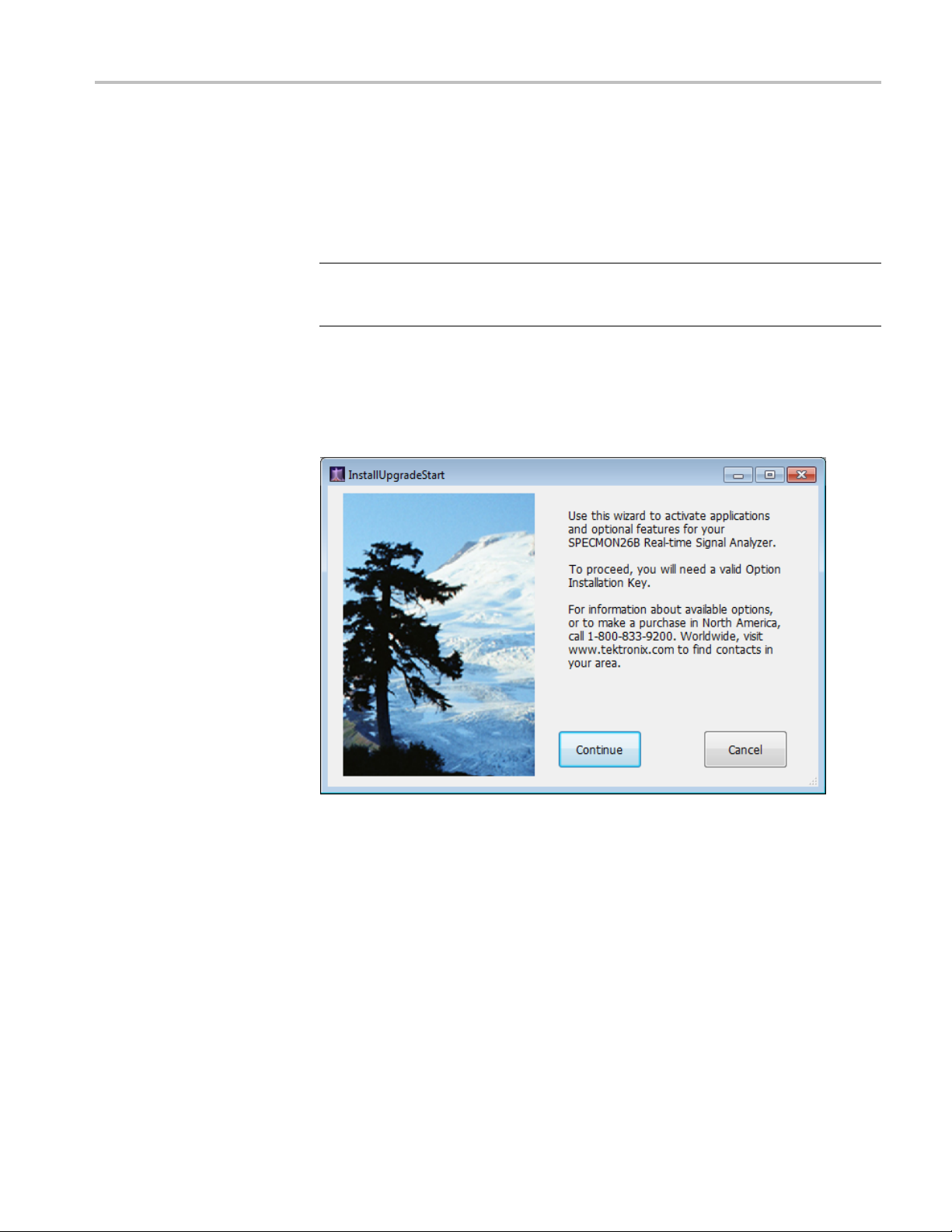
2. In the signal analyzer application, select Tools > Install Upgrades to start the
upgrade installation process.
3. Click Continue from the Install Upgrades introduction screen.
SPECMONB Series SPECMONBUP Option 300 Upgrade 9
Page 14
Installation instructions
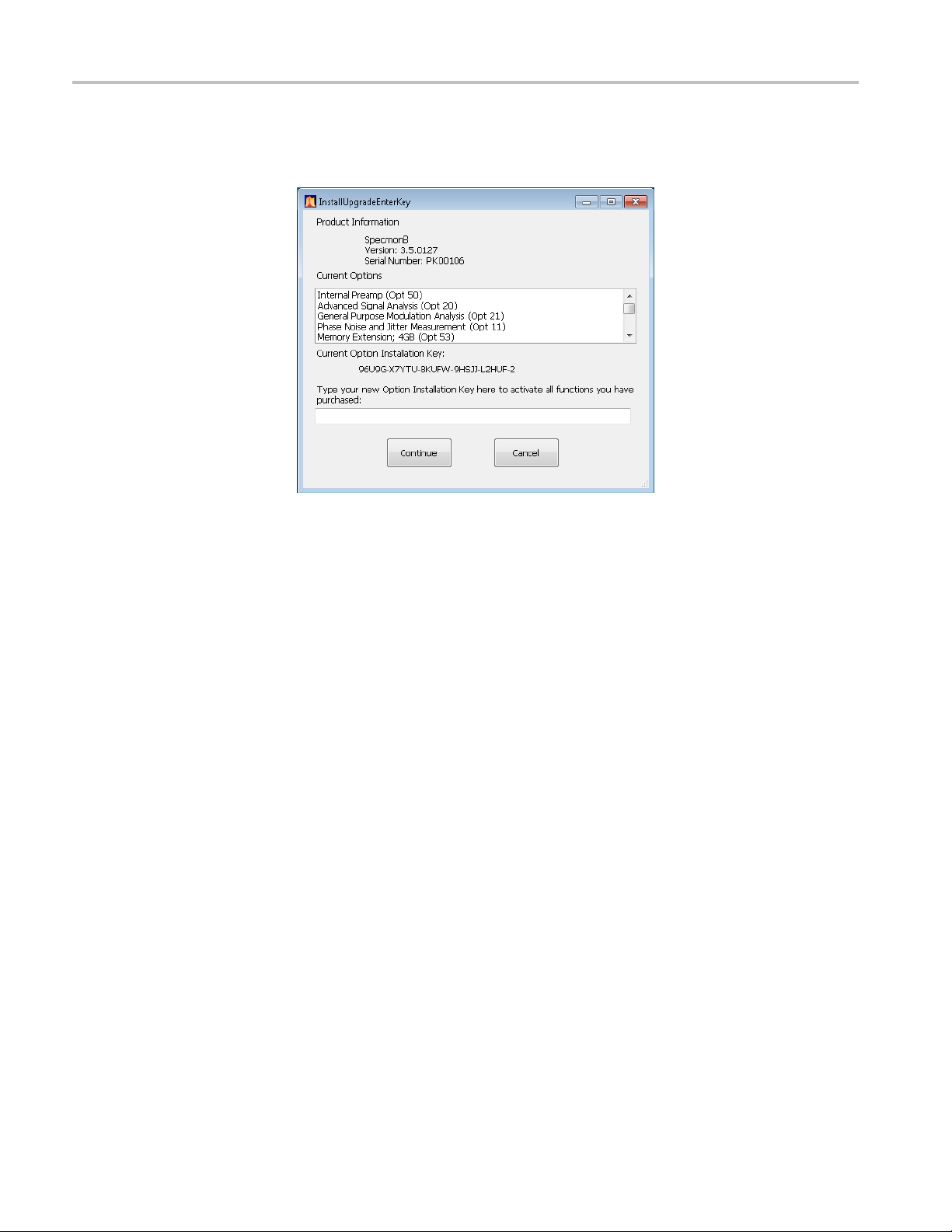
4. Enter the optio
instructions to install the option.
5. Power off the instrument, then power back on.
6. Select Help > About Tektronix Real Time Signal Analyzer.
7. In the installed Options window, verify that Option 300 is listed. It may
appear as Advanced DPX (Opt 300).
n key provided by Tektronix, and follow the on-screen
Attach labels
Attach the option key label
Attach the product/option
label
8. Click OK.
Please attach all labels provided in this kit on the instrument’s rear panel.
Place the new option key label over the existing label on the rear panel.
ce the new product label over the existing label on the rear panel.
Pla
End of Document
10 SPECMONB Series SPECMONBUP Option 300 Upgrade
 Loading...