

Page 1

xx
ZZZ
SourceXpress
®
Waveform Creation Application
Printable Help Document
*P077114505*
077-1145-05
Page 2

Page 3

SourceXpress
®
Waveform Creation Application
ZZZ
Printable Help Document
w.tek.com
ww
077-1145-05
Page 4

Copyright © Tektronix. All rights reserved. Licensed software products are owned by Tektronix or its
subsidiaries or suppliers, and are protected by national copyright laws and international treaty provisions.
Tektronix products are covered by U.S. a nd foreign patents, issued and pending. Information in this
publication supersedes that in all previously published material. Specifications and price change privileges
reserved.
TEKTRONIX and TEK are registered trademarks of Tektronix, Inc.
SourceXpress is a registered trademark of Tektronix, Inc.
Microsoft, Windows, Windows XP Professional, Windows 7, and Windows 10 are registered trademarks
of Microsoft Corporation.
MATLAB is a registered trademark of The Mathworks, Inc.
Supports SourceXpress Software Version 6.1 and above.
Help part number: 076–0381–05
PDF of Help system part number: 077–1145–05
Contacting Tektronix
Tektronix, Inc.
14150
P. O . Bo x 500
Beaverton, OR 97077
USA
SW Karl Braun Drive
For product information, sales, service, and technical support:
orth America, call 1-800-833-9200.
In N
Worldwide, visit www.tek.com to find contacts in your area.
Page 5

Table of Contents
Introduction
Welcome............................................................................................................. 1
Software ............ ................................ .................................. ............................... 3
Compatible generators ................ ................................ .................................. ........... 3
Documentation......................................... ................................ ............................. 4
Support i
Orientation
Elements of the display ............................................................................................ 5
Play button ................. ................................ .................................. ....................... 5
Menu bar............................................................................................................. 6
File menu ............................................................................................................ 6
Connectivity menu ................ .................................. ................................ ............... 8
Tools menu ......................... .................................. ................................ ............... 8
Windows menu .......... ................................ .................................. ......................... 9
Help menu........ ................................ ................................ .................................. . 9
Open and save tools ............................................................................................... 10
Restore tools ............................. ................................ .................................. ........ 11
Screen interface features ........................ ................................ .................................. 11
nformation ............. .................................. ................................ ................. 4
Table of Contents
Connectivity
Connectivity.................. ................................ ................................ ...................... 15
Generator List...................................................................................................... 15
Create a virtual generator
Create a virtual generator .................................................................................... 20
Connect to a generat or
Connect to a generator ............................... ................................ ........................ 21
Generator gangs
Generator gangs............................................................................................... 22
Create a gang of real generators............................. ................................ ................ 22
Creating a gang of virtual generators ............... ................................ ........................ 25
Connection status ........................... .................................. ................................ 26
Right-click gang menu operations ...................... ................................ .................... 27
Waveform list
Waveform list ...................................................................................................... 29
Adding a waveform ........................... ................................ ................................ .... 31
Saving a waveform ................................................................................................ 36
SourceXpress Printable Help Document i
Page 6

Table of Contents
Apply corrections (AWG70000 series).................................. ................................ ........ 37
Apply corrections (AWG5200 series)....... .................................. ................................ .. 37
Assign a waveform to a channel ............................... ................................ .................. 38
Modify waveform ................................................................................................. 40
Modify markers.................................................................................................... 43
Properties ................. .................................. ................................ ........................ 46
Applying waveform corrections
Applying Sin(x)/x correction (AWG70000 series)...................... ................................ .. 48
Applying correction file............ ................................ .................................. ........ 48
Apply S-Parameters
Apply S-Parameters .......................................................................................... 50
S-Parameter file descriptions ........................................................................... 53
Aggressor signals ........................................................................................ 55
Sequence list
Sequence list ................................... .................................. ................................ .. 57
Adding a sequence..... ................................ ................................ ............................ 58
Saving a sequence ................. .................................. ................................ .............. 60
Assigning tracks to channels ................... ................................ ................................ .. 60
Edit a sequence .................................................................................................... 62
Sequence properties ............................................................................................... 62
Sequencer batch c
Sequencer batch compiler ........................................................................................ 65
Waveform plug-ins
Waveform plug-ins introduction ................................... ................................ .............. 73
Basic waveform
Basic waveform........... ................................ ................................ .................... 74
Equation editor
Equation editor overview .................................................................................... 77
Limitations..................................................................................................... 79
Tips on using the equation editor ..................... ................................ ...................... 79
Basic keywords
Basic keywords......................... ................................ ................................ .. 81
Waveform functions
Waveform functions ..................................................................................... 82
Correlation................................................................................................ 88
Code conversion ......................................................................................... 90
Differentiation............................................................................................ 94
Integration ................................................................................................ 96
Convolution..... .................................. ................................ ........................ 97
ompiler
ii SourceXpress Printable Help Document
Page 7

Math functions
Math functions ........................................................................................... 98
Math operator
Math operators ............................. .................................. ............................ 99
Equation examples
Equation examples............................. .................................. ...................... 100
Table editor
Table editor .................................................................................................. 109
s
Sequence file format
Sequence file format (.seq) ..................................................................................... 115
Waveform file format
Waveform file format (.wfmx) ............. ................................ .................................. .. 119
Matlab waveform file format
MATLAB waveform file format ............................................................................... 125
MATLAB waveform file example ....... ................................ ................................ ...... 128
MATLAB IQ file example ...................................................................................... 129
Table of Contents
Lice
dex
In
nsing
Licensing overview.............................................................................................. 133
How to purchase a license .............................. ................................ ........................ 134
How to install a license ......................................................................................... 134
How to return a license ......................................................................................... 136
SourceXpress Printable Help Document iii
Page 8

Table of Contents
iv SourceXpress Printable Help Document
Page 9

Introduction Welcom e
Welcome
SourceXpress is a waveform creation software application. With the various optional waveform modules,
you’re able to create a wide variety of digitally modulated signals and impairment waveforms.
SourceXpress is designed to interface seamlessly with the AWG70000 and AWG5200 Series arbitrary
waveform generators, either connected to a virtual generator or connected to an instrument.
Connected to a Virtual Generator. The startup mode is for SourceXpress to connect to a Virtual generator.
By default, a virtual generator is created when the software is installed. You can configure as many
virtual generators as you want.
When connected to a virtual generator, SourceXpress provides a simulation of the instrument’s interface,
allowing you access to all controls and settings as if you were working with an actual instrument.
Because you can create as many virtual generators as you like, each with different configurations, you can
create all your waveforms, sequences, and setups specific to instrument types, all in the absence of an
instrument. Then, when an instrument is available, you can simply recall your saved files.
Connec
network for compatible instruments and connect directly to the instrument. The interface of the instrument
is displayed in the SourceXpress application window, providing you access to all instrument controls,
directly from SourceXpress. (The instrument itself displays a message that it is being externally controlled.)
You can remotely connect to multiple instruments, and control them, one at a time, via SourceXpress.
In addition, you can control an active generator via the instrument’s GPIB programming commands. You
must send the GPIB commands to SourceXpress and then SourceXpress passes the command to the active
generator. Refer to the connected instrument’s programming manual for instrument specific commands.
NOTE. Menus and controls of the active generator are not described in this help system. Refer to the
documentation for the active generator.
ted to an instrument. With SourceXpress installed on a networked PC, the software can scan the
SourceXpress Printable Help Document 1
Page 10

Introduction Welc o me
Workspace interface
The workspace provided in SourceXpress is dependent on the chosen active generator, regardless of
whether it is a virtual generator or connected to an instrument.
For operating information about the controls of the displayed generator, refer to the documentation
available for the specific instrument.
2 SourceXpress Printable Help Document
Page 11

Introduction Software
All documentation is available on the Tektronix web site (www.tek.com/manual/downloads).
Software
SourceXpress
SourceXpress is designed to operate on these Windows platforms:
Windows 7 (64-bit)
Windows 8 (64-bit)
Windows 10 (64-bit)
Compati
SourceX
ble generators
press can currently connect to and control the following generators:
AWG70001A arbitrary waveform generator
AWG70002A arbitrary waveform generator
AWG5202 arbitrary waveform generator
AWG5204 arbitrary waveform generator
AWG5208 arbitrary waveform generator
SourceXpress Printable Help Document 3
Page 12

Introduction Documentation
Documentation
In addition to this application Help system, the following documentation is available for the software.
All documentation is available on the Tektronix web site (www.tek.com/manual/downloads
To read about Use these documents
SourceXpress operation and user interface help Access t he SourceXpress application help from the Help menu for
information on all controls and elements on screen.
The SourceXpress help system is also available in PDF format, available
on the Tektronix web site. Tektronix part number 077-1145-xx.
SourceXpress programmer commands Access the SourceXpress programmer manual for the syntax of remote
commands.
This document is available in PDF format located in the program’s
installation folder and also available on the Tektronix web site. Tektronix
part number 077-1144-xx.
Connected instrument operation and user
interface help
Connected instrument programmer commands For programming information of a connected instrument, refer to the
xxx
For operation and interface help of a connected instrument, refer to the
instrument’s documentation.
This documentation is available with the instrument or on the Tektronix
web site.
instrument’s documentation.
This documentation is available with the instrument or on the Tektronix
web site.
).
Support information
Tektronix offers the following services in support of their products:
nical Support. For application-related questions about a Tektronix product, contact us by
Tech
telephone or email ).
vice Support. For service-related questions about a Tektronix product, contact us by telephone
Ser
or email ).
ktronix also offers extended warranty and calibration programs as options on many products. Contact
Te
your local Tektronix distributor or sales office.
4 SourceXpress Printable Help Document
Page 13

Orientation Elements of the display
Elements of the display
The main areas of the application window are shown in the following figure.
NOTE. The workspace area is not discussed in this document since its content is based on the type of
instrument s
the instrument’s documentation available from the Tektronix web site (www.tek.com/manual/downloads
elected as the active generator. For information about controls of the active generator, view
).
Play button
The play button starts and stops the waveform playout whenSourceXpressisconnectedtoaninstrument
and the connected instrument is set to Active in the Connected Generators tab.
SourceXpress Printable Help Document 5
Page 14
Orientation Menu bar
If a virtual generator is active (selected in the Connectivity tab), the Play button is not enabled.
Menu bar
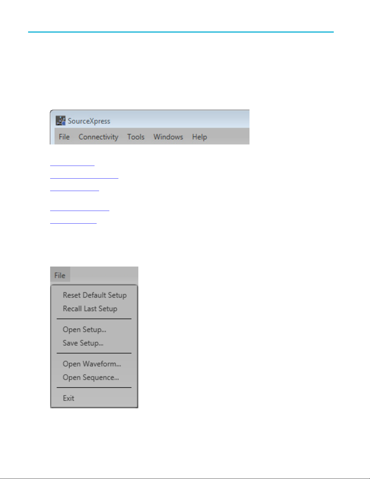
The Menu bar provides access to various actions.
File (see page 6) provides access to various open, save, and setup actions.
Connectivity
Tool s
Status bar at the bottom of the screen.
Windows
Help
(see page 9) provides access to the SourceXpress User manual and information about SourceXpress.
File menu
(see page 8) provides access to add generators to the Connected Generators tab.
(see page 8) allows you to hide pop-up error messages, forcing the errors to only show in the
(see page 9) allows you to collapse or expand the tabbed panels.
6 SourceXpress Printable Help Document
Page 15

Orientation File menu
Item Description
Reset Default Setup Returns all settings of the active generator to the factory settings.
NOTE. The cont
ents of the active generator’s Waveforms tab, Sequences tab,
and Captured Signal List are removed.
The contents of these lists of any connected instrument are not affected.
Recall Last Setup
Returns the active generator to the setup that was last accessed.
Open Setup... Opens a window to allow you to navigate to saved setup files. Opening a setup file
returns the
active generator to the settings saved with the setup file. Waveforms
and/or sequences saved with the setup file are also restored, removing all existing
waveform and sequence files .
Save Setup... Saves the current settings as a setup file, allowing you to easily return the application
to a known s
etup. A windows Save As dialog box opens to the most recent location
accessed. Use this window to navigate to where you want to save the setup.
In the Save As window, you can choose to save the setup file (which includes all
waveform
s and sequences) or s ave the setup file without the assets (which excludes
all waveforms and sequences).
The factory location is C:\Program Files\Tektronix\SourceXpress\Samples.
NOTE. Signals listed in the Capture/Playback tab are not saved as part of the
setup file.
Open Waveform... Opens a window to allow you to navigate to saved waveform files. Performs the
same actions as the Open Waveform button in the Waveforms tab, opening any of
the supported file types. Refer to Open File
depending on the type of file being opened.
Open Sequence... Opens a window to allow you to navigate to saved sequence files. To add a sequence
to the Sequences tab, select the Open Sequence button. This opens a Windows
dialog box that allows you to navigate to a saved sequence or setup file. If the
sequence or setup file is a valid file type, the sequences are added to the Sequences
tab and waveforms (used in the sequence) are added to the Waveforms tab.
Exit Exits the application.
xxx
for a description of the actions taken
SourceXpress Printable Help Document 7
Page 16

Orientation Connectivity menu
Connectivity menu
Create Virtual Generator... Displays the Create Virtual Generator dialog screen.
Enables you to create virtual generators which are added to the Generators List.
Refer to Connectivity
xxx
(see page 15) for information.
Tools menu
Item Description
e error pop-ups
Disabl
Licenses... Displays the License Management window. The License Management window
xxx
s or disables the pop-up error message windows. When disabled, error
Enable
messages only show in the status bar at the bottom of the screen.
The status bar shows the following icon to indicate that pop-up error messages
dden.
are hi
lays the installed plug-in licenses and access to install or return a license.
disp
See Licensing
(see page 133) for information about how licensing works.
8 SourceXpress Printable Help Document
Page 17

Orientation Windows menu
Windows menu
Item Description
Connected Generator List Displays or hides the Connectivity tab.
Waveform List Displays or hides the Waveforms tab.
Sequence List Displays or hides the Sequences tab.
Reset Window Layout Returns all application windows to their original location and display. For example, a ll
undocked tabs are returned to their original location and all closed tabs are reopened.
xxx
Help menu
Help & Support button: Help & Support provides links where you can obtain additional product help and
documentation. About my SourceXpress button: About my SourceXpress provides you with detailed
information about your instrument, such as installed options and software version. This information is
helpful when contacting Tektronix about your instrument. You can use the Copy Instrument Info button to
copy and paste the instrument information into another application such as an email program.
Item Description
User manual
About SourceXpress... Provides you with detailed information about your application, such as the software
xxx
This is performs the same function as the
Opens the application help system, same as the
version. This information is helpful when contacting Tektronix about your instrument.
Use the Copy System Information button to copy and paste the instrument
information into another application such as an email program.
icon in the Restore tools.
icon.
SourceXpress Printable Help Document 9
Page 18
Orientation Open and save tools
Open and save tools
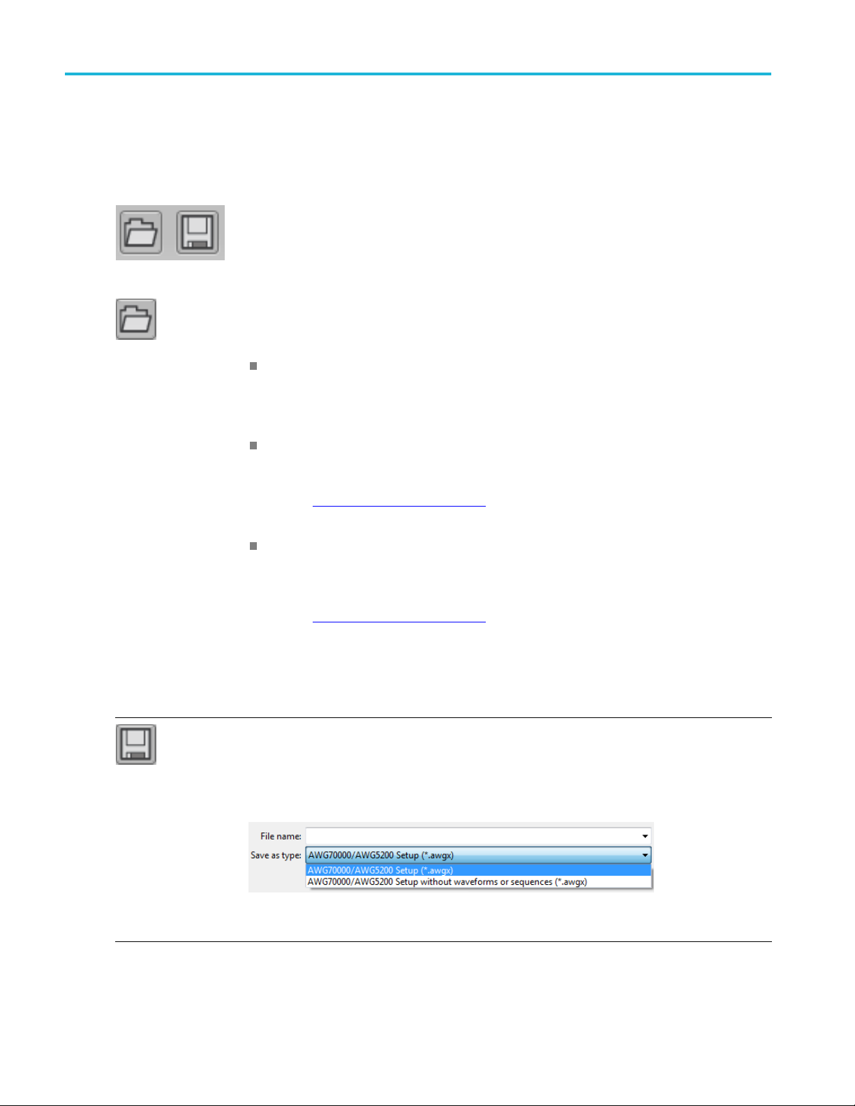
The Open and Save tools provide access to various open, save, and setup actions.
Open File allows you to open any of the supported file types. The action taken depends on
the file type opened.
Setup files: Opening a saved setup file returns the instrument to the settings saved with the
setup file. Waveforms and/or sequences saved with the setup file are also restored, removing
all existing waveforms and sequences.
Waveform files: Opening a waveform file from the toolbar allows you to select one waveform
file at a time to load into the Waveforms tab. (Matlab files that contain more than one waveform
will have all waveforms loaded into the Waveforms tab.
See Adding a waveform
(see page 31) for more information.
Sequence files: Opening a sequence file from the toolbar allows you to select one sequence
file at a time to load into the Sequence tab. If the sequence file contains subsequences, these
are also placed in the Sequences tab. All waveforms used in the sequence are loaded into
the Waveforms tab.
See Adding a sequence
A windows Open dialog box opens to most recent location accessed. Use this window to navigate
to your files.
The factory location is C:\Program Files\Tektronix\SourseXpress\Samples.
For more advanced options to add waveforms or sequences, use the Open icons located within
the Waveforms tab and Sequences tab panels.
Save Setup saves the current settings as a setup file, allowing you to easily return the active
generator to a known setup. A windows Save As dialog box opens to the most recent location
accessed. Use this window to navigate to where you want to save the setup.
In the Save As window, you can choose to save the setup file (which includes all waveforms
and sequences) or save the setup file without the assets (which excludes all waveforms and
sequences).
The factory location is C:\Program Files\Tektron
(see page 58) for more information.
ix\SourceXpress\Samples.
NOTE. Signals listed in the Capture/Playback tab are not saved as part of the setup file.
xxx
10 SourceXpress Printable Help Document
Page 19

Orientation Restore tools
Restore tools
The Restore tools provide access to various actions to return the application to known setups and graphical
layout.
Reset to De
NOTE. The contents of the Waveforms tab, Sequences tab, and Captured Signal List are
removed.
The contents of these lists of any connected instrument are not affected.
Restore Last Setup returns the application to the setup that was last accessed.
Reset Wi
The User
xxx
ndow Layout returns all window panels (moved or undocked) to their original locations.
Manual button displays the help system.
Screen interface features
The graphical user interface (GUI) is designed with some features that are only accessible via t he right
and left mouse clicks.
fault Setup returns all settings of the active generator to the factory settings.
SourceXpress Printable Help Document 11
Page 20

Orientation Screen interface features
Left mouse clic
Right mouse click
Pull down lists
k
Left mouse clic
Right mouse cl
In some instances, a right mouse click is the only method to access some menus. For instance,
right click on one of the generators in the Connected Generators list to display the menu to activate,
disconnect, o
Selections with a triangle incorporate a pull-down list. Left mouse click on the triangle to display
the list.
k on any control or setting to select or activate that control.
ick on various areas, controls, and settings display a menu of available actions.
r display instrument properties.
Drag a
nd drop
Use the left mouse click to drag a waveform from the Waveforms tab onto the waveform display
area. If a waveform is already attached to the channel, the waveform is replaced. If the previous
orm was currently playing, the new waveform starts playing immediately.
wavef
12 SourceXpress Printable Help Document
Page 21
Orientation Screen interface features
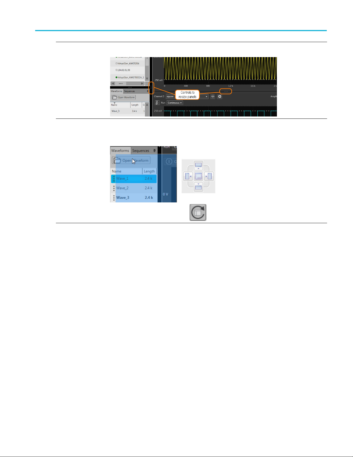
Window resizing The various window panels can be adjusted in size where-ever two panels are divided. Use the
right mouse cl
ick to grab the 3 dot indicator and slide to increase or decrease its size.
Undocking and
docking tabs
xxx
Any tab can be undocked from the GUI. This allows you to reposition a tab to a new location
or completely separate it from the main GUI. Use a left mouse click to grab a tab and slide it
to a new area. The docking icon displays that you can use to choose how you want to dock
(reposition) the tab.
Use the R
eset Window Layout button
to return the display to the factory settings.
SourceXpress Printable Help Document 13
Page 22

Orientation Screen interface features
14 SourceXpress Printable Help Document
Page 23

Connectivity Connectivity
Connectivity
The Connectivity tab contains the list of generators that are currently connected (or available for
connection) to SourceXpress, whether it’s a virtual generator or a real instrument. You can connect as
many generat
At the initial startup of SourceXpress, an AWG70002A Virtual generator is created and connected. This is
the default
the active generator and displays a simulated AWG70002A interface.
ors as you wish, but only one can be one active.
generator, named VirtualGen_AWG70002. As the default generator, it is automatically set to be
You can cre
There must always be a default generator.
Virtual Generator. The default mode of operation is for SourceXpress to connect to the default virtual
generator. You can create other virtual generators, each with different configurations. Once you create
additional virtual generators, you can choose a different default virtual generator. (Right mouse click in the
Avai lab
When connected to a virtual generator, you can create all your waveforms, sequences, and setups specific
to inst
simple recall your saved files.
Connected to an instrument. With SourceXpress installed on a networked PC, SourceXpress can remotely
connect and control any compatible generator
becomes the active generator, the interface of the generator is displayed in the SourceXpress application
ow, providing you access to all its controls, directly from SourceXpress.
wind
ate additional virtual generators and choose which generator is the default active generator.
le Virtual Generators screen to select the default generator.)
rument types, all in the absence of an instrument. Then when an instrument is available, you can
Generator List
The Connectivity tab contains your list of available generators connected (or available for connection) to
urceXpress. You can connect to as many generators as you wish (virtual generators and instruments),
So
but you can only have one active at a time.
(see page 3) on the network. When the connected generator
NOTE. When SourceXpress is connected to a generator, the generator’s display will indicate that it is
being externally controlled. Control of the generator can easily be regained directly from the generator’s
display, or by disconnecting the generator from SourceXpress via the Generator List.
SourceXpress Printable Help Document 15
Page 24
Connectivity Generator List
When SourceXpress is started for the first time, one Virtual generated is created and appears in the
Generator List as the active generator along with the simulated display of the generator.
As you modify the Generat or List (add/remove generators (virtual or real instruments), SourceXpress
retains the latest list of generators and repopulates the list when SourceXpress is restarted.
When SourceXpress is restarted, SourceXpress populates the Generator List as follows:
All previously existing virtual generators appear in the Generator List and are connected.
eviously existing real generators appear in the Generator List but are not connected unless
All pr
Auto Connect is checked for that generator. If Auto Connect is checked, SourceXpress attempts
to reestablish a connection.
If a virtual generator was the active generator at shut down, the same virtual generator is active.
real generator was the active generator at shut down, the same generator will be connected and
If a
be the active generator if SourceXpress is able to reestablish a connection. If the connection can not
be established with the generator, an error message is displayed.
Virtual Generators
You can create as many virtual generators you like, each with different configurations. Use the
Connectivity > Create Virtual Generator... menu to display the dialog screen to create a new generator.
When connected to a v irtual generator, you can create all your waveforms or sequences, create setups
pecific to a generator type, all in the absence of a real instrument. Then when a generator is available,
s
you can simple recall your saved files.
16 SourceXpress Printable Help Document
Page 25

Connectivity Generator List
Connect to instruments
With SourceXpress installed on a networked PC, SourceXpress can remotely connect to and control any
compatible generator on the network. The interface of the generator is displayed in the SourceXpress
application window, providing you access to all generator controls, directly from SourceXpress.
Instrument search/connect
The connect
of a networked generator you wish to connect to.
After ente
searching for the generator. When the connection is established, the generator is added to the Generator
List. The name appearing in the Generator List is the same as entered in the Connectivity window. You
can rename a generator by selecting it and use the right-click rename menu.
To obtain the hostname or IP address of an instrument, go to the target generator, select Computer >
Properties and note the computer name or IP address.
ivity tab provides a window for you to enter the computer name (hostname) or IP address
ring the hostname or IP address, select the magnifying glass (or press Return) to initiate
Selecting the active generator
From the Connectivity tab, you select which generator you want to access, regardless if it’s a virtual
generator or a connected real generator. Making the generator active brings its display into view.
Right-click on the generator name and select Set to Active from the pop-up window.
Next to the name of each generator, the Type of generator is displayed to help identify real generators
from virtual generators.
nection status indicators
Con
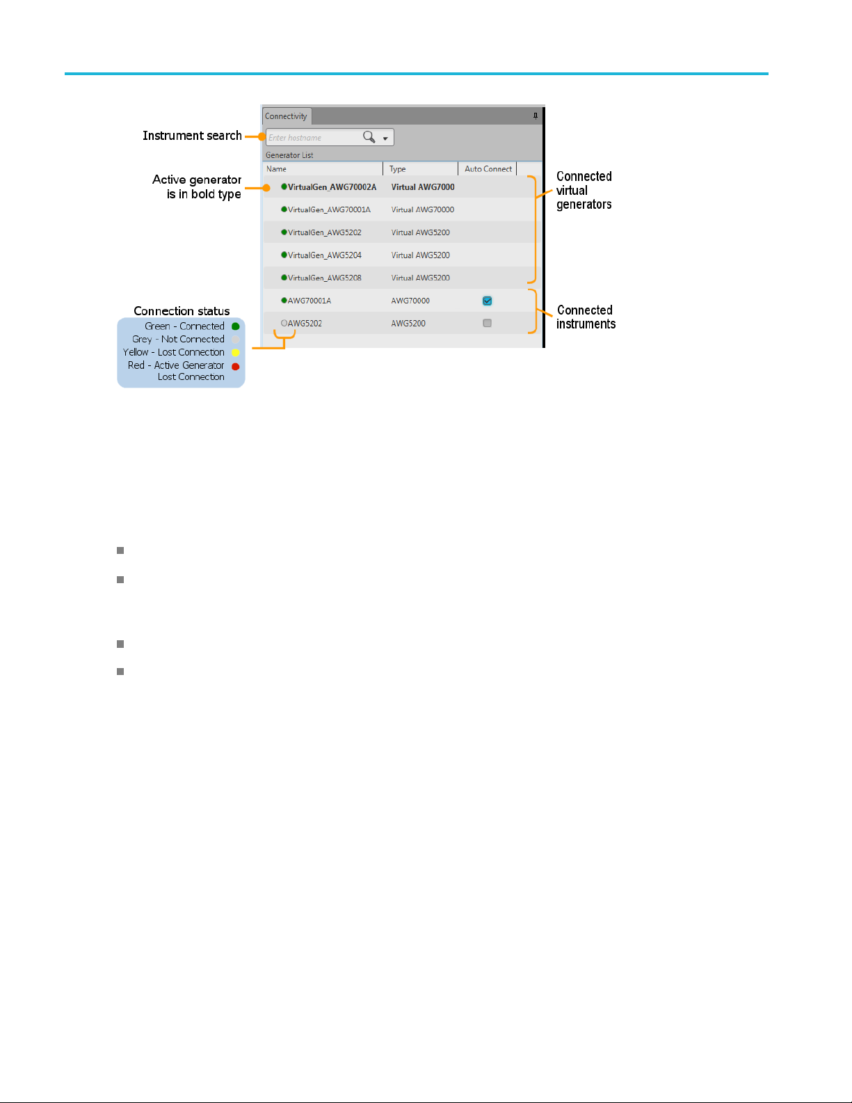
Next to each generator name in the Generator List (see page 18) is a colored icon to indicate the connection
atus of that generator.
st
Green indicates SourceXpress is connected to the generator. Virtual generators are always connected.
Grey indicates SourceXpress is not connected to the generator.
Yellow indicates SourceXpress lost connection to the generator but it was not the active generator.
Red indicates SourceXpress lost connection to the generator and it was the active generator.
SourceXpress Printable Help Document 17
Page 26

Connectivity Generator List
Status indicators
Auto Connect
Use the A
SourceXpress is launched. You can choose to automatically reconnect to any or all instruments (currently
in the Generator List) when SourceXpress is launched.
Auto Connect is not available for virtual generators since they are connected at all times.
uto Connect feature to automatically establish a connection to the selected instrument when
Right-click menu operations
Right-click on a generator name displays a menu of actions. The menus are different between a virtual
generator and a real generator as noted below.
18 SourceXpress Printable Help Document
Page 27

Connectivity Generator List
NOTE. Right-click menus differ for AWG70000 series generators contained in a Gang. Refer to Generator
gangs (see page 22).
Item Description
Set to Active Sets the selected generator to the active generator, bringing its controls into view.
Only one active generator is allowed at a time.
Connect Establishes a connection from SourceXpress to the selected generator. This item is
gray if the generator is already connected.
This is not available if a virtual generator is selected. Virtual generators are always
connected.
Disconnect
Remove
Disconnects the selected generator from SourceXpress. The generator name
remains in the Generator List and can be reconnected with the Connect menu. This
item is gray if the generator is already connected.
This is not available if a virtual generator is selected. Virtual generators are always
connected.
Removes the selected generator from the Generator List. If the generator is
connected, it is first disconnected.
NOTE. You cannot remove the default virtual generator.
Add to Gang Allows you to add the selected AWG70000 series generator to a generator gang.
This menu item is gray if no gangs exists.
See the topic Generator gangs
gangs and a their use.
(see page 22) for information about created generator
NOTE. Add to Gang is only available when an AWG70000 series generator is
selected.
SourceXpress Printable Help Document 19
Page 28

Connectivity Create a virtual generator
Item Description
Set to Default Sets the selected virtual generator as the default generator to display.
ilable for real generators.
ename dialog screen for the selected generator. If a generator has
Rename
Properties
xxx
This is not ava
Displays the R
been renamed, you can locate its original name by displaying the Properties of
the generator.
Displays the system information about the selected generator.
Create a virtual generator
The Connectivity menu allows you to create virtual generators, each with its own set of properties, such
as a two-channel or single-channel instrument to simulate the actual instrument you may connect to in
the future. As virtual generators are created, they are added to the Generator List in the Connectivity
age
tab (see p
To create a virtual generator, select the menu Connectivity > Create Virtual Generator...
15).
This displays the Create Virtual Generator window.
20 SourceXpress Printable Help Document
Page 29

Connectivity Connect to a generator
You can create additional virtual generators, each with its own set of properties, such as a two-channel or
single-channel instrument to simulate the actual instrument you may connect to in the future.
Item Description
Name
Define a name for the generator you are creating.
By default, the name is given a base name of VirtualGen with the model type
appended to the name. If needed, the name is appended further with a numerical
value.
You can overwrite the Name field entirely by typing in a generator name.
NOTE. You cannot duplicate or overwrite an existing Virtual Generator name.
Models
Options Choose the options you want to be included with your simulated model. The options
Set as default generator When checked, the generator being created becomes the default generator in the
Create Creates the generator as defined, and adds the named generator to the Generator
Cancel Exits out of the Create Virtual G enerator window without creating any new generators.
xxx
Choose the model you want to simulate
selections change depending on the model selected. This allows you to choose only
options appropriate for the selected model.
Generator List in the Connectivity tab. The default generator can be changed in the
Generator List window.
List (see page 15) in the C onnectivity tab.
Connect to a generator
To connect to a generator, use the search field in the Connectivity tab.
NOTE. If the Connectivity tab is not displayed, enable the setting “Connected Generator List” located in
the Windows menu or press the Reset Windows Layout button.
ter the computer name (Hostname) or the IP address of a networked generator you wish to connect to.
En
Select the magnifying glass to initiate searching for the named generator.
f the generator is found, it is added to the Generator List and connected to SourceXpress.
I
NOTE. TCP/IP port 59557 is required to be open for the WCF (Windows Communication Foundation)
connection. For example, when communicating through a router.
SourceXpress Printable Help Document 21
Page 30

Connectivity Generator gangs
Once a generator is connected to SourceXpress, the generator’s display is disabled. A message is displayed
indicating it is being remotely controlled. The connection can be disabled directly from the instrument’s
screenbyendi
ng the remote session.
Generator gangs
Generator gangs is a way to group up to four AWG70000 series generators together as a single gang
of generators, displaying all channels together in the Home screen. This gives the appearance of a
multi-channel g enerator, displaying up to 8 channels (four AWG70002A generators ganged together).
The gang appears in the Generator List and is treated like other generators. The connection status
page 26) is shown by the colored icons next to the name. If the gang is the active generator(s), the name
appears b
NOTE. Generator gangs can only be created with AWG70000 series generators. AWG5200 series cannot
be ganged together or included within a gang of AWG70000 series generators.
old in the list.
Gangs can consist of 2 to 4 generators.
A gener
and two-channel generators within the same gang.
Gener
A generator within a gang can be removed (unless synchronization is enabled) but a gang must have at
leas
The active generator can be a gang or a member of a gang.
You cannot remove a generator from a gang once sychronization has been enabled.
A g ang of generators can be created with virtual generators or real generators. (A gang cannot mix the
two types.) Virtual generator and Real generator gangs act similarly except for:
ator gang can only be created of like generators. For instance, you cannot mix single-channel
ators within a gang can be set to the active generator. This causes only that generator to display.
t two generators.
(see
Real generators must be connected to an AWGSYNC01 Synchronization Hub, with the master
and slave generators defined.
A gang of real generators (connected to an AWGSYNC01 Synchronization Hub) automatically
have their master/slave status set, and the Sync Enable activated.
Create a gang of real generators
NOTE. When creating a gang of real generators, all generators must be connected to an AWGSYNC01
Synchronization Hub.
22 SourceXpress Printable Help Document
Page 31

Connectivity Create a gang of real generators
1. Select the g enerators you want to gang together, then right click to display the Create Gang menu.
You can gang up to four generators.
The selected generators must all be of the same m odel and connected to a sync hub.
2. The gang is created, containing the selected generators.
You can see the generators by clicking the arrow icon next to the gang name to expand and collapse
the list of generators contained in the gang.
3. In this example, we’ve ganged two 1-channel generators together. With the gang selected as the active
generator, it displays as two channels.
4. Select the Setup tab to display the settings for the generator gang.
First, notice that the Sync tab is displayed.
SourceXpress Printable Help Document 23
Page 32

Connectivity Create a gang of real generators
5. Click Enable to automatically set the generators to synchronize with the AWGSYNC01
Synchronization Hub.
As you can
generator connected to Port 2 is a slave.
Also not
6. Select Channel under the Setup tab.
With the gang as the active generator, the Channel p ull-down menu now shows two channels.
If you were to create a gang of four 2-channel instruments, the pull-down list would contain eight
channels.
see, the generator that was connected to Port 1 of the Sync Hub is the master, and the
ice in the Generators list that the generators are identified as master and slaves.
24 SourceXpress Printable Help Document
Page 33

Connectivity Creating a gang of virtual generators
Creating a gang of virtual generators
The creation of a gang of virtual generators is almost identical to the process of real generators. The
differences are:
Virtual generators are not connected to a synchronization hub,
When Sync is enabled for the gang (in the Sync menu in the Setup tab), the generators will be assigned
ports as if they were connected to a hub.
The first listed generator in the gang becomes the master generator.
SourceXpress Printable Help Document 25
Page 34

Connectivity Connection status
Connection status
Next to each generator gang name in the Generator List is a colored icon to indicate the connection status
of that gang of generators. There are slight differences of the connection status indicators for a gang to
the status of
a generator.
Gang connection status
Green indicates that SourceXpress is connected to all generators in the gang.
Grey indicates that SourceXpress is not connected to one or more generators in the gang.
ow indicates SourceXpress has lost connection to one or more generators in the gang, but the gang
Yell
was not the active generator.
indicates SourceXpress lost connection to one or more generators in the gang and the gang was
Red
the active generator.
Generator connection status
Green indicates SourceXpress is connected to the generator. Virtual generators are always connected.
Grey indicates SourceXpress is not connected to the generator.
ellow indicates SourceXpress lost connection to the generator but it was not the active generator.
Y
Red indicates SourceXpress l ost connection to the generator and it was the active generator.
26 SourceXpress Printable Help Document
Page 35

Connectivity Right-click gang menu operations
Right-click gang menu operations
A right click on the generator name displays a menu of actions. The menus and actions are different
between a gang and a gang member.
Item Description
Set to Active Sets the selected gang or gang member as the active generator.
An active gang brings all channels of the gang together.
ve gang member only displays that generator.
An acti
Remove For gangs only.
s the selected gang and all of its members from the Generator List. If it is a
ng members only.
A gang must have at least two members.
lays the Rename dialog screen. If a generator has been renamed, you can
Remove from Gang
Rename
erties
Prop
xxx
Remove
gang of real generators, the generators are first disconnected.
For ga
Removes the selected gang member from the gang. If the gang member is a
connected real generator, it is first disconnected.
NOTE.
Disp
locate its original name by displaying the Properties of the generator.
Displays the s ystem information about the selected generator.
SourceXpress Printable Help Document 27
Page 36

Connectivity Right-click gang menu operations
28 SourceXpress Printable Help Document
Page 37

Waveform list Waveform list
Waveform list
The Waveform List contains the waveforms available to assign to a channel.
You can drag and drop a waveform from the Waveform list onto the channel’s graph area, assigning that
waveform to play on the channel. See below when working with IQ waveforms.
Right-mouse click on a waveform to display a pop-up menu of tools to modify waveforms, assign a
waveform to a channel, save, remove waveforms, and view a waveform’s properties.
IQ waveforms (display)
AWG70000 series. IQ waveforms cannot directly be assigned to play on a channel, only the I or Q
components can be played out.
AWG5200 series. IQ waveforms can directly be assigned to play on a channel if the Digital Up Converter
(DIGUP) is licensed. Otherwise, only the individual I or Q components can be assigned.
When adding an IQ waveform to the Waveforms List, the I and Q components are separated and a sublist
is created under the IQ waveform. Use the arrow next to the IQ waveform name to expand or collapse
the sublist.
Use the sublist to assign the I or Q components to a channel for playout.
SourceXpress Printable Help Document 29
Page 38

Waveform list Waveform list
IQ waveform (create)
If you have I and Q waveform files, you can use the Waveform list to combine them into an IQ waveform.
From within the Waveform List, select both the I and Q waveforms.
NOTE. The waveform selected first becomes the I waveform. The waveform selected second becomes
the Q waveform.
With the selections made, display the right-click menu and select Make IQ Waveform. The I and Q
waveforms must be of equal length.
A new IQ waveform is generated using the first selected waveform as the I component and the second
selected waveform as the Q component. Hovering over the menu displays a tool tip showing which
orm is I and which waveform is Q.
wavef
he name of the IQ waveform generated uses the name of the I waveform (without suffix"_I"or"_Q")
T
andisappendedwith"_IQ".
30 SourceXpress Printable Help Document
Page 39

Waveform list Adding a waveform
Adding a waveform
To add a waveform to the Waveform List, select the Open Waveform button. This opens a Windows
dialog box that allows you to navigate to a stored waveform, setup file, or sequence file. (You can load
waveforms contained in Setup files and sequence files.)
If the waveform is a valid waveform type, the waveform is added to the Waveform List. Once a waveform
is in the Waveform List, it can be assigned to a channel for playout. Click here to see the list of valid
waveform file types.
Valid file types Description
.AWGX file format Setup file created by Tektronix AWG5200/AWG70000 Series instruments or
SourceXpress.
Setup files can contain multiple waveforms and multiple sequences.
NOTE. Opening a setup file from the Waveform List does not restore the instrument
settings, only the waveforms contained in the setup file are restored.
.WFMX file format Created by Tektronix AWG5200/AWG70000 Series instruments or SourceXpress.
.AWG file format Setup file created by Tektronix AWG5000 or AWG7000 Series instruments.
NOTE. The Tektronix AWG5000 or AWG7000 Series instruments had predefined
waveforms available for use.
Saved setup files that used predefined waveforms did not save the actual waveform
data with the setup, only the waveform name. Hence, importing setup files that
used predefined waveforms will not import the waveforms. To import these types of
waveforms, first copy and rename the predefined waveform, then save the setup file
before importing.
.WFM file format Created by Tektronix AWG5000/7000 Series instruments.
Created by Tektronix AWG400/500/600/700 Series instruments.
Created by Tektronix TDS/DPO/MSO/DSA Series instruments.
SourceXpress Printable Help Document 31
Page 40

Waveform list Adding a waveform
Valid file types Description
at
mat
file format
ts
ts
Created by Tek
Created by Tek
Created by Te
Created by T
instruments. or SignalVu-PC.
Matlab file type for RSA6000/5000 Series and SPECMON Series.
ceXpress. (Also can be a subsequence.)
Sour
ence file created by Tektronix AWG400, AWG500, or AWG600 Series
Sequ
instruments. (Also can be a subsequence.)
.ISF file forma
.PAT file forma
.IQT file form
.TIQ file for
.TFW file format Created by Tektronix AFG3000 Series instruments.
.TXT file format Created by Tektronix AWG5000 or AWG7000 Series instruments.
.RFD file format Created by Tektronix RFX100 RFXpress Advanced RF/IF/IQ waveform software.
.SXD file format Created by Tektronix SDX100 SerialXpress high-speed serial data signals software.
.MAT file format Matlab file type (Level 5 or Level 7.3) for AWG5200/AWG70000 Series.
.TMP file format Midas BLUE file type.
.PRM file format Midas BLUE file type.
With the Sequen c ing option (Option 03), the following files types are also valid waveform sources.
.SEQX file format Sequence file created by Tektronix AWG5200/AWG70000 Series instruments or
.SEQ
xxx
tronix TDS/DPO/MSO/DSA Series instruments.
tronix AWG400/500/600/700 Series instruments.
ktronix RSA3000 Series instruments.
ektronix RSA6000/5000 Series, SPECMON Series ,MDO4000 Series
If selecting a file type containing multiple waveforms (.AWGX, .MAT, .AWG, .SEQX), you are presented
with the Available Waveforms dialog box
u can load all the wa veforms or select a subset of the waveforms.
Yo
(see page 33) that lists all waveforms contained in the setup file.
NOTE. When opening a setup file (.AWGX) from the Waveform List, only the waveforms are extracted;
instrument settings contained in the setup file are not restored. Use the File > Open Setup... menu in the
Menu bar
(see page 10) to restore b oth the settings and waveforms from a .AWGX setup file.
If you want any of the waveforms (extracted from a setup file) to be available outside of the setup file,
select and save each individual waveform.
32 SourceXpress Printable Help Document
Page 41

Waveform list Adding a waveform
Available waveforms
Non-navtive analog files
When adding analog waveform file types that are not native to the AWG, you are presented with the
Importing waveform dialog screen
Waveform List.
(see page 33) to normalize (rescale) the waveform while adding to the
Import waveform
SourceXpress Printable Help Document 33
Page 42

Waveform list Adding a waveform
Digital text waveform file
When adding a digital text (.TXT) waveform file, an Import Digital Waveform Text File dialog box
displays to specify the digital bit resolution of the file before the waveform is added to the Waveform List.
Choose from the following:
AWG70000 Series
8 Bits (waveform + 2 markers): For 10 bit files that use 8 bits for data, and two bits for markers.
9 Bits (wave
10 bits: For 10 bit files without markers.
AWG52 0 0 Series
12 Bits (waveform + 4 markers): For 16 bit files that use 12 bits for data, and four bits for markers.
13 Bits (waveform + 3 markers): For 16 bit files that use 13 bits for data , and three bits for markers.
14 Bits (waveform + 2 markers): For 16 bit files that use 14 bits for data, and two bits for markers.
15 Bits
16 bits: For 16 bit files without markers.
It’s important to know the details of your waveform before you import so you do not affect the integrity of
the waveform. For instance, selecting 10 bits for a waveform that is intended to use 8 bits for data and two
or markers will add the marker bits to the waveform data and markers will not be available.
bits f
(waveform + 1 marker): For 16 bit files that use 15 bits for data, and one bit for a marker.
(see page 34)
form + 1 marker): For 10 bit files that use 9 bits for data, and one bit for a marker.
(see page 35)
AWG70000 import digital waveform text file
34 SourceXpress Printable Help Document
Page 43

Waveform list Adding a waveform
AWG5200 import digital wa veform text file
NOTE. If sequencing is available, waveforms are also added to the Waveform List when loading a
sequence file or setup file that contains a sequence.
IQ files
When adding an IQ waveform file (.TIQ), the waveform is added to the Waveform list but with a sublist
of its I and Q components. You cannot assign the IQ file directly to a channel on the home screen, only
the I or Q components can be assigned.
You can assign the I and Q components to channels for playout. If the connected instrument contains an IQ
modulator, you can assign the IQ waveform to a channel.
NOTE. You can select to modify an IQ waveform. The modify dialog screen does support displaying an IQ
waveform. See the section Modify waveform dialog screen
(see page 41).
Multi-waveform select
Through the Open Waveform menu in the Waveform List, you can select multiple waveform files to load
into the waveform list at once.
To select a contiguous block of files, click the first file in the block. Then hold down the Shift key as you
click the last file in the block. This will select not only those two files, but everything in between.
To select multiple files that are not a contiguous block, click one file. Then hold down the Ctrl key while
you click each additional desired file.
SourceXpress Printable Help Document 35
Page 44

Waveform list Saving a waveform
If your selection includes sequence files or setup files, all waveforms saved with those file types are
loaded into the waveform list.
CAUTION. Load
ing groups of waveforms will overwrite any existing waveform of the same name in the
Waveform List without warning.
NOTE. Multi
ple file selection is available via the Open Waveform menu. Loading waveforms from the
Open File menu (in the tool bar) or from the pull-down list in the graphical waveform area does not
support multiple file selection.
Saving a waveform
To save a waveform, right mouse click on a wavefor m and select Save or Save As. This opens a Windows
dialog box that allows you to navigate to a location to save the waveform.
Click here to see the list of valid waveform file types.
Valid file types Description
.WFMX file format Native waveform file.
.WFM file format Tektronix AWG400/500/600/700 series waveform file.
.TXT file format Waveform file.
.TIQ Valid for IQ waveforms. For Tektronix SignalVu-PC.
xxx
Maximum waveform size is l imited to <200 M.
36 SourceXpress Printable Help Document
Page 45

Waveform list Apply corrections (AWG70000 series)
Apply corrections (AWG70000 series)
Right click on any waveform (or two waveforms for I/Q correction) and select the Apply Corrections menu.
With the Apply Corrections dialog screen, you can choose to apply one of two types of correction:
Sin(x)/x distortion correction
Apply a correction file (coefficient file)
For information about the two types of correction, refer to these sections:
Apply Sin(x)/x correction (see page 48)
Apply correction file (see page 48)
Apply corrections (AWG5200 series)
Right click on any waveform (or two waveforms for I/Q correction) and select the Apply Corrections menu.
SourceXpress Printable Help Document 37
Page 46

Waveform list Assign a waveform to a channel
With the Apply Corrections dialog screen, you can choose to apply a correction file (coefficient file)
to the waveform
For information about the correction file, refer to:
Apply correction file (see page 48)
Assign a waveform to a channel
To play a waveform, you need to assign it to a channel. This is true even for a single channel instrument.
There are several methods to assign a waveform to a channel.
Drag a waveform from the Waveform List onto a channel’s plot area.
ght mouse click on a waveform name in the Waveform List and use the pop-up window to assign
Ri
it to a channel.
38 SourceXpress Printable Help Document
Page 47

Waveform list Assign a waveform to a channel
Use the drop-down list in the channel’s plot area to assign the channel to play a waveform.
You can choose waveforms already loaded into the Waveform List or you can browse for waveform
files. Selecting a waveform by browsing, the waveform is added to the Waveform List and assigned
to the channel for playout.
If Sequencing is available, you can also open a sequence type file and load any of the waveforms
that were saved with the sequence.
SourceXpress Printable Help Document 39
Page 48

Waveform list Modify waveform
Modify waveform
You can select any waveform contained in the Waveform List to modify it or create a new waveform based
on the existing waveform. But note the following conditions:
Any waveform can be modified by selecting Modify Waveform > {Resample / Scale/Offset /
Rotate/Shift / Pattern}. Select one of these waveform modifiersdisplaystheModify Waveform
page 41) dialog screen.
(see
If selecting a waveform that was created with a Waveform Plug-in, a menu choice is ad
directly to the specific Waveform Plug-in editor screen.
With an S-Parameter license, you also have the option to apply S-Parameters to the waveform. Refer
to the section about Applying S-Parameters
Select a waveform in the Waveform List and right mouse click to display the waveform operations.
(see page 50).
dedtotakeyou
40 SourceXpress Printable Help Document
Page 49
Waveform list Modify waveform
Select one of the waveform modifiers to display the Modify waveform dialog screen (see page 41).
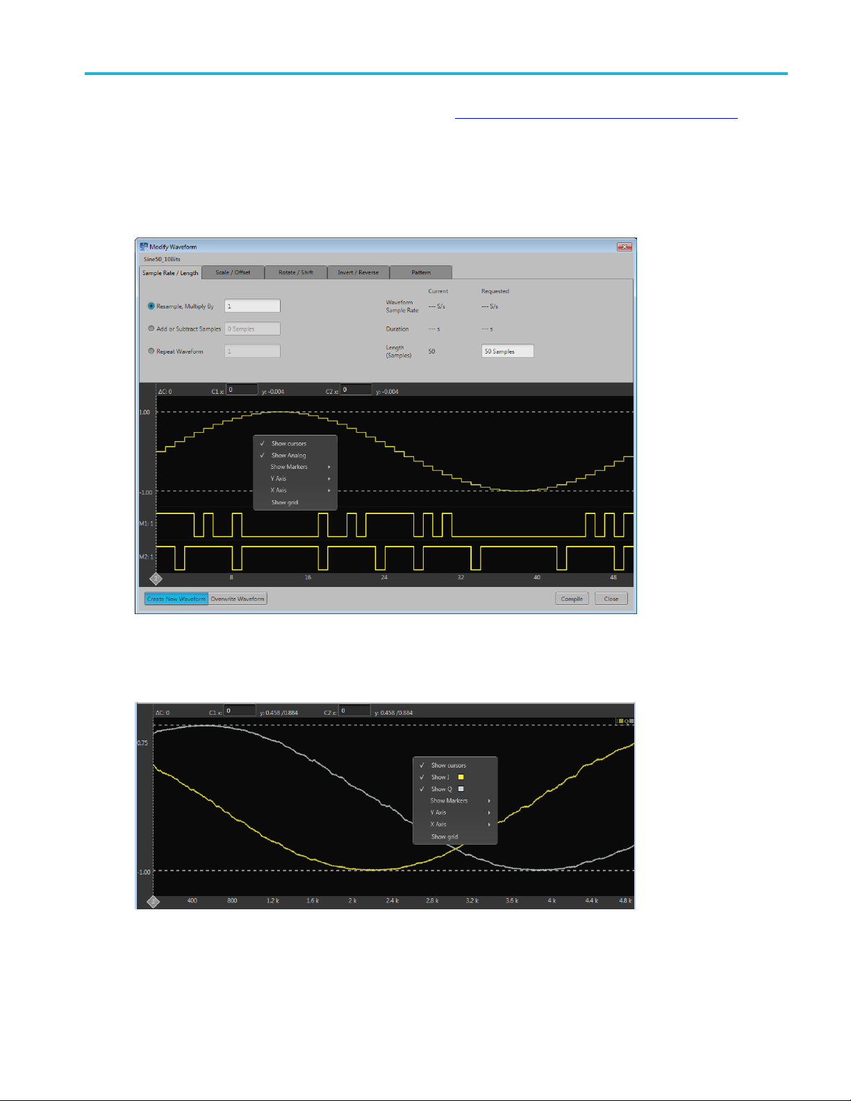
Modify wavefo
The Modify waveform dialog screen provides you with the controls and settings to modify a waveform
and save it as
rm dialog screen
a new waveform or overwrite the original waveform.
If modifying an IQ waveform, the I and Q waveforms are displayed. The I waveform color uses the color
assigned to the channel; the Q waveform is show in gray.
Here are tips and notes about using the Modify Waveform feature:
SourceXpress Printable Help Document 41
Page 50

Waveform list Modify waveform
The waveform must be in the Waveform List.
New or modified waveforms are placed in the Waveform List, but are not automatically saved to the
hard drive (or other location). They do become part of the setup file if the setup is saved. To make a
modified waveform available for use in other setups, select the modified waveform and use Save or
Save As to sav
e the waveform.
Only one modification is allowed at a time, requiring you to compile the new waveform for each
modificatio
n. This avoids any uncertainty of modifications since some modifications can affect other
characteristics.
Some modifi
cations may cause a reduction in fidelity to the new waveform.
The waveform displayed in the dialog screen represents the modified waveform before compiling.
SampleRate/Lengthtab
Resample, Multiply
By
Add or Subtract
Samples
Repeat Waveform Duplicates the waveform the defined number of times.
Scale / Offset tab
Multiply by
Normalization
Presets
Rotate / Shift tab
Rotate waveform,
wrap samples
Shift waveform,
repeat sample to
fill
Increases the number of samples of the waveform.
Adds samples to the end of the waveform by repeating the last sample of the waveform.
The scale and offset tab allows you to modify the output amplitude and offsets using the Multiply
by value. Fractional values are allowed.
You can use the Show more options check box to display and adjust individual settings.
Only the analog data is modified. Markers are not affected.
The Scale to Max Amplitude adjusts all values to obtain the full scale amplitude of 500 mVpp.
The Max & preserve Offset adjusts the values to their maximum value while preserving the o ffset
value.
Enter a value in degrees or number of samples to rotate the waveform horizontally. Rotating the
waveform takes the end of the waveform (defined by the degrees or samples) and moves it to
the front of the waveform.
Enter a value in degrees or number of samples to shift (or move) the waveform horizontally.
Shifting moves the waveform and repeats the first waveform sample value to fill in the waveform.
42 SourceXpress Printable Help Document
Page 51

Waveform list Modify marker s
Rotate / Shift t
Apply Rotatio
To
Invert/Reverse
Invert
Reverse
Range
All Samples All samples affects the entire analog and marker signals.
Between Cursors You can define a particular segment of the waveform to invert or reverse. If cursors are not
Pattern tab
See the Modify markers (see page 43) section on using the Pattern features.
xxx
ab
n/Shift
Rotation and S
Select which components of the waveform you wish to invert.
Select which components of the waveform you w ish to reverse.
Select the range of samples you want to invert or reverse.
All samples affects the entire analog and marker signals.
Between Cursors
displayed, they are automatically enabled.
Move the cursors to define the affected area.
The waveform display has the same control functions as those for the waveform in the Home
tab, such as zooming.
hift is available for the analog data and the markers.
Modify markers
You can select any waveform contained in the Waveform List to modify the waveform markers.
lect a waveform and right mouse click to display the waveform operations.
Se
SourceXpress Printable Help Document 43
Page 52

Waveform list Modify markers
Select Modify Markers to display the Pattern editor tab in the Modify Waveform dialog screen.
The pattern editor allows you to modify the Analog w aveform and/or the Markers. Once you’ve defined
your changes, you need to compile the new waveform. By default, a new waveform is created (based on
the existing name) and is placed in the Waveform List.
The controls are described below.
Pattern Type. Three patterns are available:
44 SourceXpress Printable Help Document
Page 53

Waveform list Modify marker s
High: The sample points (all samples or between cursors) are set to their high values. Marker samples
are set to 1. The analog waveform samples are set to the waveform maximum value.
Low: The sample points (all samples or between cursors) are set to their low values. Marker samples
are set to 0. The analog waveform samples are set to the waveform minimum value.
Pulse: The sample points (all samples or between cursors) alternate between their high and low values
for the defined number of samples.
When choosing Pulse, additional settings are displayed:
Start Level defines whether the cycle of pulses start from their high or low value.
High Steps defines h ow many sample points are set to high.
Low Steps defines how many sample points are set to low.
The combined number of samples for the High and Low steps are limited to the number of samples
available in the waveform
The number of pulse cycles is calculated and displayed. The number of cycles based on the number of
samples used for the high and low steps and if it’s being applied to the entire waveform or between
cursors.
NOTE. An invalid pulse definition (such as 0 samples for the high or low steps) will not let the waveform
pile.
com
Apply Modifications To. The modificationscanbeappliedtotheanalogwaveformandthemarkers. By
default, only the markers are selected.
Range. You can apply the pattern modifications to the entire waveform (All Samples) or between the
cursors.
SourceXpress Printable Help Document 45
Page 54

Waveform list Properties
If you select Between Cursors then the cursors are automatically turned on. This also turns on the
cursors in the Home tab. Position the two cursors on the displayed waveform in order to define where
the pattern i
The waveform display has the same control functions as those for the waveform in the Home tab, such
as zooming.
s applied.
Properties
You can select any waveform contained in the Waveform List to view its properties.
Select a waveform and right mouse click to display the waveform operations.
Select Properties to display the Waveform Properties dialog screen.
46 SourceXpress Printable Help Document
Page 55

Waveform list Properties
The Waveform Properties dialog screen provides many details about the waveform that are static (not able
to modify), such as the name, length, and signal format.
The Signal Format displays the type of waveform, which will show one of the following:
Real: Waveform containing data other than I, Q, or IQ.
I: Waveform contains I data.
Q: Waveform contains Q data.
IQ:Wa
The items you are able to modify include:
OTE. Recommended settings are used when the system is defined to use the waveform settings instead
N
of the system settings during playout.
veform contains IQ data.
Recommended Sample Rate: Typically defined by the waveform when it was created, you can
change the recommend sample rate as needed.
Recommended Amplitude: Typically defined by the waveform when it w as created, you can change
the recommend amplitude as needed.
Recommended Offset: Typically defined by the waveform when it was created, you can change the
recommend offset as needed.
Recommended Frequency: IQ waveforms only. Typically defined by the waveform when it was
created, you can change the recommend frequency as needed.
SourceXpress Printable Help Document 47
Page 56

Waveform list Applying Sin(x)/x correction (AWG70000 series)
Applying Sin(x)/x correction (AWG70000 series)
Select the Sin(x)/x distortion correction to apply to the waveform. The End Frequency of the Sin(x)/x
distortion correction is initially set to ½ the recommended sample rate of the waveform.
Distortion correction coefficients are defineduptotheEndFrequency. FIRfilter is applied to the impulse
response (smooth roll-off).
Choose to either create a new waveform or overwrite the existing waveform and select Apply.
Applying correction file
Correction files for waveforms can contain two types of coefficients, RF coefficients or IQ coefficients.
RF coefficients can be applied to Real, I, or Q files. Select a single waveform and apply the correction
file.
IQ coefficients must be applied to two waveforms, I and Q. Select the two waveforms (high lighting
both at the same time) and apply the correction file.
A window opens to allow you to navigate to the saved coefficient file (correction file).
48 SourceXpress Printable Help Document
Page 57

Waveform list Applying correction file
Use the browse folder icon to navigate to a saved correction file.
Choose to either create a new waveform or overwrite the existing waveform.
Onceavalidfile path is entered, the Correction Settings icon
display the Frequency Response screen.
If applying an RF correction file, the Frequency Response screen shows plot information and provides
Advanced options to apply a Gaussian filter o r remove Sin(x)/x distortions.
is enabled. Select the Setting icon to
If applying an I/Q correction file (to a pair of I and Q waveforms), the Frequency Response screen shows
plot information and provides Advanced options to apply a skew.
SourceXpress Printable Help Document 49
Page 58

Waveform list Apply S-Paramete rs
Apply S-Parameters
S-Parameters (scattering parameters) can be applied to RF waveforms or IQ waveforms in the Waveform
List.
NOTE. The S-Parameter selection becomes available only if an S-Parameter license is currently installed.
ing to apply S-Parameters displays the Apply S-Parameter dialog screen to select the S-Parameter
Select
file and define its characteristics.
Below
being modified, the S-Parameters dialog screen provides additional selections to apply the parameters to
the I component, Q component, or both I and Q.
The information provided for S-Parameters apply to both the Non-Cascading and Cascading modes.
is a sample S-Parameter dialog screen with the Number of Ports set to 4. If an IQ waveform is
50 SourceXpress Printable Help Document
Page 59

Waveform list Apply S-Parameters
SourceXpress Printable Help Document 51
Page 60

Waveform list Apply S-Paramete rs
Item Description
Mode
Select Non-Cascading or Cascading S-parameter mode.
In the Non-Cas
from only one S-parameter file.
In the Cascading mode, you can cascade up to six S-parameter files in Stages and
apply the characteristics on the signal. You can select the files to apply by turning on
or turning off the corresponding Stages shown in the display. All the selected files
should be of the same type. The settings depend on the selected type of file.
cading mode, you apply S-parameter characteristics on the signal
The files supported are s1p, s2p, s4p, s6p, s8p, and s12p.
De-embed
(Non-Cascading mode)
Cascading De-embed
(Cascading mode)
Bandwidth
Check the box to invert the S-Parameters from the signal. This removes the effects
of the component (for which the S-Parameters were created) from the signal path.
Auto – The bandwidth is defined at the point where the signal rolls off to -60 dB. If
this results in a bandwidth greater than the instrument supports, the bandwidth is set
to ½ of the waveform’s sample rate (i.e. Nyquist Frequency).
Full Bandwidth – The bandwidth is set to ½ of the waveform’s sample rate (i.e.
Nyquist Frequency).
Manual – The bandwidth can set by the user from 1 Hz to ½ of the maximum sample
rate of the instrument. If the set Bandwidth is greater than the Nyquist (Sample rate
of the w aveform/2), then the s oftware limits the bandwidth to ½ of the waveform’s
sample rate. A warning message is provided.
52 SourceXpress Printable Help Document
Page 61

Waveform list Apply S-Parameters
Item Description
Number of Ports Choose the number of ports. The port matrixes supported are 1, 2, 4, 6, 8, and 12.
The number of p
• The type of S-Parameter file to apply
• The Signalling Scheme choice
• The port mat
S-Parameter
Signallin
(Only for 4, 8, and 12 ports)
Selection of the port
(No port s
environments)
Victim
Aggress
(Only for 8 and 12 ports)
Port Selection The Port Selection button is available only when in Cascading mode. Press the
File
g Scheme
election for 1 Port
or and Both
Navigatetot
that you are able to open is dependent on the number of ports selected. For instance,
only .s4p files can be opened if the Number of Ports is set to 4.
The files sup
Signle-En
the file to physical locations in your link.
Differential: If the data is differential, you must select the data layout in the file.
Use the diagrams to map the ports for the transmitter ports (Tx-Port) and the receiver
ports (Rx
When choosing the number of Ports, you are presented with an active diagram of
the ports. The diagram presented reflects the Number of Ports selected and the
ing Scheme (if appropriate for the ports selected).
Signall
The default setting with no cross-talk effects.
Victim:
Aggressor: Select this to activate aggressor signal parameters, adding the effect
of cross-talk.
Port Selection button to display an active dialog screen to map the ports for the
itter ports (Tx-Port) and the receiver ports (Rx-Port) for each stage.
transm
orts selected determines:
rixes available
he Touchstone file to apply to the signal. The type of Touchstone files
ported are s1p, s2p, s4p, s6p, s8p, and s12p.
ded: If the data is single-ended, you must map the port numbers as used in
-Port).
xxx
S-Parameter file descriptions
1-port
Files with one port of data contain only one S-parameter file (s1p) so they do not require any further input.
SourceXpress Printable Help Document 53
Page 62

Waveform list Apply S-Paramete rs
2-port
Files with data for two ports contain four S-parameters as a 2x2 matrix. These are Touchstone 2-port files
p). A dialog box is created to define the 2-port m apping.
(s2
4-Port
Files with data for four ports contain 16 S-parameters as a 4x4 matrix. These are Touchstone 4-port files
(s4p). They may contain single-ended or differential data. A dialog box is created to define the 4-port
mapping for either single-ended or differential data.
If the data is single-ended, you must map the port numbers as used in the file to physical locations in
your link.
You can select the port for both transmitter and receiver from the drop-down list. Each drop-down list
has ports from 1 to 2.
If the data is differential, you must select the data layout in the file.
6-port
Files with data for six ports contain 36 S-parameters as a 6x6 matrix. These are Touchstone 6-port files
(s6p). A dialog box is created to define the 6-port mapping.
8-Port
Files w ith data for eight ports contain 64 S-parameters as an 8x8 matrix. These are Touchstone 8-port files
(s8p). They may contain single-ended or differential data. A dialog box is created to define the 8-port
mapping for either single-ended or differential data.
If the data is single-ended, you must map the port numbers as used in the file to physical locations in
your link.
You can select the port for both transmitter and receiver from the drop-down list. Each drop-down list
has ports from 1 to 4.
If the data is differential, you must select the data layout in the file.
12-Port
Files with data for 12 ports contain 144 S-parameters as an 12x12 matrix. These are Touchstone 12-port
files (s12p). They may contain single-ended or differential data. A d ialog box is created to define the
12-port mapping for either single-ended or differential data.
If the data is single-ended, you must map the port numbers as used in the file to physical locations in
your link.
You can select the port for both transmitter and receiver from the drop-down list. Each drop-down list
has ports from 1 to 6.
If the data is differential, you must select the data layout in the file.
54 SourceXpress Printable Help Document
Page 63

Waveform list Apply S-Parameters
Aggressor signals
8 and 12 port S-parameters allows you to activate aggressor signal parameters and to add the effect of
cross-talk. 12 port S-parameters allows 2 Aggressor signal parameters.
Aggressors can be added in either Non-Cascading Mode or Cascading Mode.
The Aggresso
Item Description
Signal Choose the type of aggressor signal with the dropdown list:
Data Rate
Aggressor Amplitude Enter the signal amplitude.
Crosstalk Type Choose the type of crosstalk of the aggressor signal.
xxx
r signal parameters include:
•Clock:Ind
• PBRS: Also choose the number of bits
• File: Indicates that the aggressor signal is another pattern file. Navigate to
the Patter
• Same as victim: The signal flow of the aggressor is same as the victim.
Specify the data rate (in bps) of the signal.
This is not available when the Aggressor signal is set to be the same as the victim.
This is not available when the Aggressor signal is set to be the same as the victim.
• Near-
• Far-End Crosstalk
• Both
icates that the aggressor signal is a clock pattern.
n file
End Crosstalk
SourceXpress Printable Help Document 55
Page 64

Waveform list Apply S-Paramete rs
56 SourceXpress Printable Help Document
Page 65

Sequence list Sequence list
Sequence list
NOTE. When connected remotely to an instrument, the connected instrument must have Sequencing
enabled.
The Sequences list contains the available sequences. Right-mouse click on a sequence to display a pop-up
menu of tools to modify, rename, save, copy, and remove sequences.
To add a sequence to the list, see Adding a sequence
(see page 58).
To play a sequence track, it needs to be assigned to a channel. Refer to Assigning tracks to channels
(see page 60).
Right-mouse click on a sequence to display a pop-up menu of tools to modify, rename, save, copy, and
remove sequences.
Item Description
Modify Sequence Opens the Sequence tab and loads the selected sequence into the sequence editor.
Make a Copy Creates a copy of the selected sequence and places the copy in the Sequence List. The
y is renamed by adding a numerical suffix to the end of the original name.
cop
ve
Sa
ve As ...
Sa
ename
R
ves the sequence to the specified location.
Sa
ens a window to save the sequence with a new file name. This only changes the file
Op
name, it does not change the sequence name that appears in the Sequence List.
Changes the sequence name currently displayed in the Sequence List.
Use Save or Save As .... to save the sequence with the new name.
SourceXpress Printable Help Document 57
Page 66

Sequence list Adding a sequence
Item Description
Remove
Remove All
Properties
Use remove to remove the selected sequence(s).
Remove All rem
Displays info
oves all sequences from the Sequence List.
rmation about the sequence. Refer to the section Sequence properties
(see page 62).
xxx
Adding a sequence
To add a sequence to the Sequences List, select the Open Sequence button. This opens a Windows dialog
boxthatallowsyoutonavigatetoasavedsequenceorsetupfile. If the sequence or setup file is a valid
file type, t
to the Waveform List. Once a sequence is in the Sequences List, a sequence track can be assigned to a
channel for playout. (See Assign a track to a channel.)
Click here to see a list of valid sequence file types.
Valid sequence file types Description
.SEQX file format Sequence file created by Tektronix AWG70000/AWG5200 Series instruments or
.AWGX file format Setup file created by Tektronix AWG70000/AWG5200 Series instruments or
he sequences are added to the Sequence List and waveforms (used in the sequence) are added
(see page 60)
SourceXpress.
SourceXpress.
Setup files can contain multiple sequences and multiple waveforms.
NOTE. Opening a setup file from the Sequence List does not restore the
instrument settings, only the sequences contained in the setup file are restored
along with any waveforms used in the sequences.
.AWG file format Setup file created by Tektronix AWG5000 or AWG7000 Series instruments.
NOTE. The Tektronix AWG5000 or AWG7000 Series instruments had predefined
waveforms available for use.
Saved setup files that used predefined waveforms did not save the actual waveform
data with the setup, only the waveform name. Hence, importing setup files that
used predefined waveforms will not import the waveforms. To import these types of
waveforms, first copy and rename the predefined waveform, then save the setup
file before importing.
NOTE. The Tektronix AWG5000 or AWG7000 Series instruments supported
subsequencing (using another sequence as a step in a sequence). Subsequences
are imported as another sequence and added to the Sequences list.
.SEQ file format Sequence file created by Tektronix AWG400, AWG500, or AWG600 Series
instruments.
xx
x
If selecting a setup type file containing multiple sequences, you are presented with the Available Sequences
(see page 59) dialog box that lists all sequences contained in the setup file. You can load all sequences or
select a subset of the sequences. Waveforms that are part of any sequence are added to the Waveform List.
58 SourceXpress Printable Help Document
Page 67

Sequence list Adding a sequence
Available sequences
NOTE. Whe
sequences are extracted; instrument settings contained in the setup file are not restored. Use the Open
Setup in the File menu to restore the settings, waveforms, and sequences from a .AWGX setup file.
If you want any of the waveforms or sequences (extracted from a setup file) to be available outside of the
setup file, select and save each individual waveform.
n opening a setup file (.AWGX) from the Waveforms or Sequences tabs, only waveforms and
Multi-sequence select
Though the Open Sequence menu in the Sequences List, you can select multiple sequence files to load
into the sequence list at once.
To select a contiguous block of files, click the first file in the block. Then hold down the Shift key as you
click the last file in the block. This will select not only those two files, but everything in between.
To select multiple files that are not a contiguous block, click one file. Then hold down the Ctrl key while
you click each additional desired file.
CAUTION. Loading a group of sequences will overwrite any existing sequence of the same name in the
quences List without warning.
Se
NOTE. Multiple sequence selection is not available from the Open File menu in the tool bar or from the
ull-down list in the graphical waveform area.
p
SourceXpress Printable Help Document 59
Page 68

Sequence list Saving a sequence
Saving a sequence
To save a sequence, right mouse click and select Save or Save As. This opens a Windows dialog box that
allows you to navigate to a location to save the sequence.
Click here to see the list of valid sequence file types.
Valid file types Description
.SEQX file format Native sequence file.
.SEQ file format Sequence file for AWG5000 and AWG7000 series instruments.
xxx
Assignin
A sequenc
sequence track, you need to assign it to a channel. This is true even for a single channel instrument.
There ar
regarding one channel and two channel instruments.)
Drag an
Drag a track from a sequence onto a channel’s plot area.
Right mouse click on a sequence track in the Sequences tab and use the pop-up window to assign
it to a channel.
g tracks to channels
e can consist of up to eight different tracks. (A minimum of one track is required). To play a
e several methods to assign a sequence track to a channel. (See below for further information
entire sequence onto a channel’s plot area.
Use the drop-down list in the channel’s plot area to assign the channel to play a sequence track.
You can choose sequence tracks from sequences already loaded into the Sequences tab or you can
rowse for sequence files. When browsing, you select the sequence file, and then select the track to
b
assign to the channel.
60 SourceXpress Printable Help Document
Page 69

Sequence list Assigning tracks to channels
Assigning tracks on a one channel instrument
With a one channel instrument, the following actions occur when assigning a track to play on the channel:
If you drag and drop a sequence onto the channel’s graph area, Track 1 is assigned to the channel. This
is true regardless of how ma
You can drag and drop (or assign) any track from any sequence onto the channel’s graph area.
ny tracks the sequence may contain.
Assigning tracks on a two channel instrument
With a two channel instrument, you have the
or different sequences. You also have the option to play a sequence track on one of the channels while
playing a single waveform on the other.
The following describes the interactions between the two channels:
You can drag and drop the entire seque nce onto one of the c hannel’s graph area. This automatically
assigns Track 1 of the sequence to the channel.
If the sequence has only one track, you can drag and drop the sequence to one or both channel’s
graph area and the single track will play on both channels.
If the sequence has multiple tracks, you can drag and drop the sequence to either channel’s graph
area. Inthiscase,Track1isassignedtoChannel1andTrack2isassignedtoChannel2.Thisis
the track assignment regardless of which channel you drag the sequence to.
If playing tracks from the same sequence on both channels, the channels are coupled together.
This requires that the waveforms be of equal length for each step of the two tracks. In this case,
the Force jump to... buttons are coupled together. (Coupled Sequence is displayed on the Home
tabwhentracksfromthesamesequence are assigned to both channels.)
option to play multiple tracks, either from the same sequence
You can drag and drop (assign) a specific track from different sequences onto the channel’s graph area.
SourceXpress Printable Help Document 61
Page 70

Sequence list Edit a sequence
This gives you the freedom to play any track from any sequence. Since the tracks are from different
sequences, the channels are not coupled together.
You can play a sequence track on one channel while playing a waveform on the other channel.
Assigning tr
IQ waveforms cannot be assigned to a channel for playout, only their I or Q components can be assigned to
a channel.
Sequence tracks that contain an IQ waveform provide a drop down menu for you to choose which
component
the I or Q selection applies to all IQ waveforms in the track.
acks containing IQ waveforms
of the IQ waveform you want the channel to play. If a track contains multiple IQ waveforms,
Edit a sequence
You can select any sequence contained in the Sequences tab to modify it or create a new sequence based on
the existing sequence. Select any sequence in the list, right mouse click to display the sequence operations.
Selecting Modify sequence opens the sequence in the Sequences tab window for editing.
Sequence properties
You can select any sequence contained in the Sequence List to view its properties.
62 SourceXpress Printable Help Document
Page 71

Sequence list Sequence properties
The Sequence Properties dialog screen provides many details about the Sequence that are static (not able
to modify). The items you are able to modify include:
Recommended Sample Rate: This is typically defined by the sequence when it was created. You can
change the recommend sample rate as needed.
Recommended Amplitude: This is typically defined by the sequence when it was created. You can
change the recommend amplitude as needed.
Recommended Offset: This is typically defined by the sequence when it was created. You can
change the recommend offset as needed.
Recommended Frequency: This is typically defined by the sequence when it was created and is only
displayed if the sequence contains an IQ waveform. You can change the recommended frequency
as needed.
Recommended settings are used when the system is defined to use the sequence settings instead of the
system settings during playout.
SourceXpress Printable Help Document 63
Page 72

Sequence list Sequence properties
64 SourceXpress Printable Help Document
Page 73

Sequencer batch compiler Sequencer batch compiler
Sequencer batch compiler
The batch compiler provides a method to create sequences and waveforms using an Excel spreadsheet
(.CVS file type) and then importing the file into the AWG. The comma delimited file type (.CSV) must be
used.
To import the batch compiler file, you must use the Open File folder from the toolbar.
Opening the file compiles all defi ned waveforms and loads the sequence into the Sequences tab and loads
all wavefo
The waveforms created by the batch compiler are limited to:
rms into the Waveforms tab.
Basic waveforms via the use of the Basic Waveform plug-in
Create sine waves, square waves, triangle waves, ramps, noise, and DC
RF waveforms via the use of the RF Generic Signal plug-in. A license for the RF Generic Signal
plug-in is required.
Create AM, FM, and PM Analog Modulation signals
Creating a batch compile file (.CSV)
The .csv file must be created with very specific information in the proper cells. Deviating from this
design will likely create an invalid file. The following information defines the rows, columns, and cell
content required to create the batch file.
E. The Samples directory (C:/Program Files/Tektronix/SourceXpress/Samples) contains a sample
NOT
batch file (Batch Compile Example.csv) that you can use as a basis to create your own batch file. The
sample batch file contains the proper header information and basic track definitions.
Header inform ation. The first four lines in column A must use the content as shown.
SourceXpress Printable Help Document 65
Page 74

Sequencer batch compiler Sequencer batch compiler
Table 1: Batch compiler header information
Line Column A Column B (Optional)
Line 1
Mandatory
Line 2
(Optional)
Line 3
(Optional)
Line 4
(Optional)
xxx
AWG Sequence Definition
Sequence Name Enter a name for your sequence. If omitted, the
Sample Rate Enter the sampling rate to use. If omitted, the system
Waveform Name Base Enter the base name for the waveform files. Use the
blank
system w
calcula
frequency specified.
following syntax:
<base
quency_#Length_#Marker1_#Marker2....]
The base name is used for all waveforms.
You c a
by including the parameter column heading, preceded
by a # sign.
If om
ill generate a unique name.
tes the sample rate based on the waveform
name> [#Fre-
n also include any of the waveform parameters
itted, the system will generate unique names.
Track information. Following the header information is the start of the track definitions. You can create up
to eight tracks containing multiple waveforms.
Each new track definition must start by creating a row with the name “Track” in cell A. This row signifies
where the definition of each track begins.
The following row contains the headings for the waveform parameters. Note that some headings are global
definitions while some headings define elements for each waveform. And the required and optional
elements change based on the waveform editor you invoke (Basic or RF). See the tables below that
describe the column contents depending on the waveform editor chosen.
66 SourceXpress Printable Help Document
Page 75

Sequencer batch compiler Sequencer batch compiler
A track can have many waveforms, with each waveform creating a new step in the sequence. The
waveform definitions continue for the Track until another “Track” row is encountered. When defining
multiple trac
The following illustrates the spreadsheet representing the columns for creating a basic waveform (using
the Basic Wav
ks, each track must contain the same number of waveform definitions.
eform plug-in).
The following illustrates the spreadsheet representing the columns for creating an RF waveform (using the
RF Gener
ic Signal plug-in).
SourceXpress Printable Help Document 67
Page 76
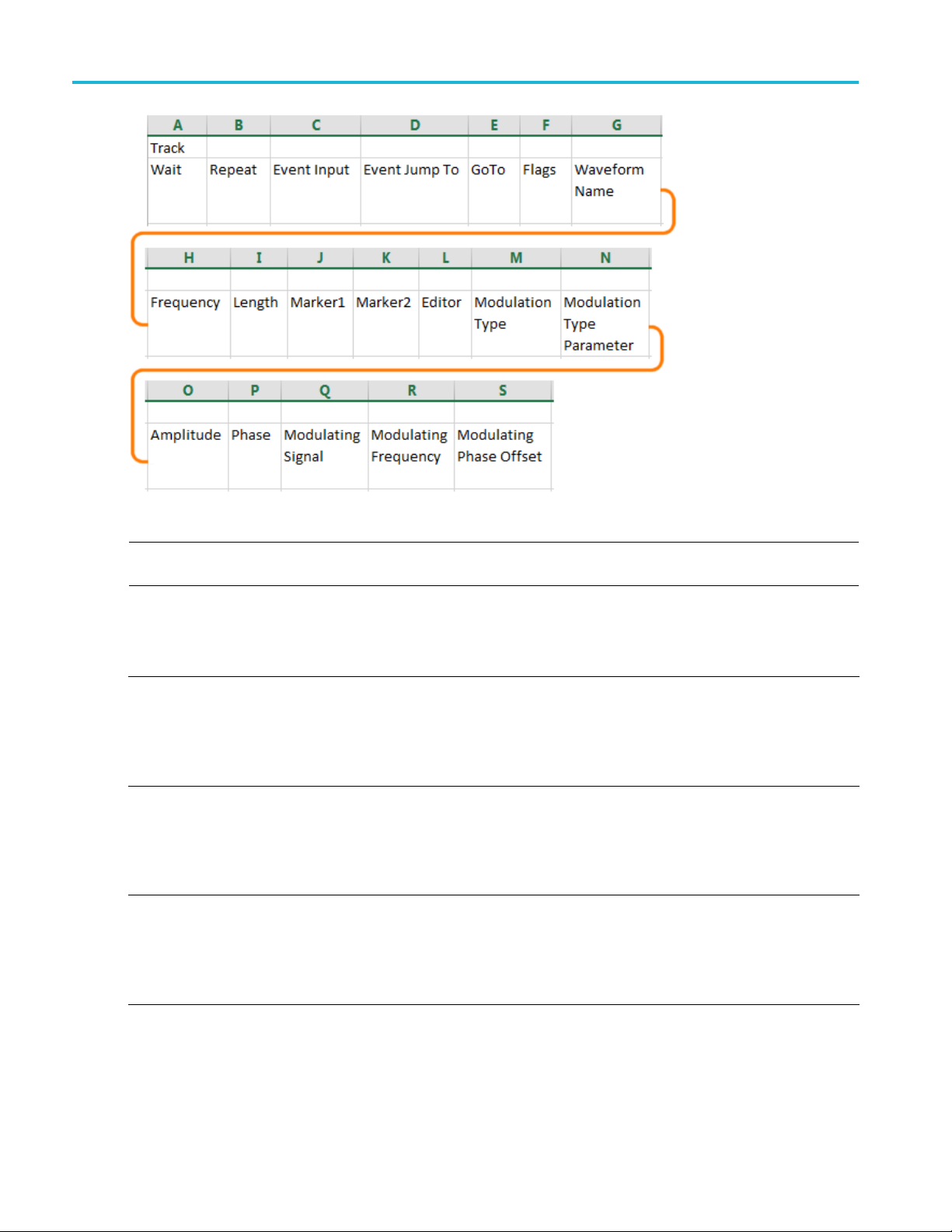
Sequencer batch compiler Sequencer batch compiler
NOTE. Creating an RF waveform uses the RF Generic Signal plug-in. The RF Generic Signal must be
licensed for use.
Table 2: Batch compiler header: editor = Basic Waveform plug-in
Column
AWait
B Repeat
C
Event Input
Optional: Wait condition.
This is a global setting for all tracks and must be defined in the first
track.
Syntax: <Off | TrigA | TrigB | Internal>
If omitted, set to Off.
Optional: R epeat element.
This is a global setting for all tracks and must be defined in the first
track.
Syntax: <<Integer> | ∞>
If omitted, set to 1.
Optional: Event input.
This is a global setting for all tracks and must be defined in the first
track.
Syntax: <Off | TrigA | TrigB | Internal>
If omitted, set to Off.
68 SourceXpress Printable Help Document
Page 77

Sequencer batch compiler Sequencer batch compiler
Table 2: Batch compiler header: editor = Basic Waveform plug-in (cont.)
Column
D Event Jump To
E
F F lags
G Waveform Name Optional: Waveform name. This supersedes the Waveform Name
H Frequency
I Length
JMarker1
KMarker2
Add column Marker3
Add column Marker4
Go To Optional: Go To element.
Optional: Event jump.
This is a global setting for all tracks and must be defi ned in the first
track.
Syntax: <<step number> | Next | First | Last | End>
If omitted, set to Next.
This is a global setting for all tracks and must be defi ned in the first
track.
If omitted, set to Next.
Optional: Flag element. If defining flags, you must define all four
flags. Use semicolons (;) to separate the flag definitions.
Syntax: <FlagA;FlagB;FlagC;FlagD>
Values include: Toggle | High | Low | Pulse | NoChange
If omitted, set to NoChange.
Base in the header information.
If omitted, the Waveform Name Base is used.
Specifies the frequency of the waveform to be compiled.
Specifies the length in sample points of the waveform to be compiled.
If omitted, the system calculates the length.
Optional: Marker1 value.
Syntax: <0 | 1>
If omitted, set to 0.
Optional: Marker2 value.
Syntax: <0 | 1>
If omitted, set to 0.
(AWG5200 series only)
Optional: Marker1 value.
Syntax: <0 | 1>
If omitted, set to 0.
(AWG5200 series only)
Optional: Marker1 value.
Syntax: <0 | 1>
If omitted, set to 0.
NOTE. The sample batch file provided includes columns for two
Markers. AWG5200 series can support up to four marker columns.
This changes the column assignments of the remaining parameters.
SourceXpress Printable Help Document 69
Page 78

Sequencer batch compiler Sequencer batch compiler
Table 2: Batch compiler header: editor = Basic Waveform plug-in (cont.)
Column
LEditor
M
Waveform Type Defines the type of waveform to create when Editor = Basic
N Amplitude
OOffset Defines the offset.
xxx
Optional: Editor to use to compile waveform.
Syntax: <Basic Waveform>
If omitted, set to Basic Waveform.
Use Parameter columns to set the Basic Waveform function.
The Basic Waveform editor supports all functions of the Basic
Waveform plug-in.
Waveform.
Syntax: <Function=[Sine | Square | Triangle | Ramp | Noise | D C>
If omitted, set to Sine.
Sets the peak-to-peak amplitude.
Syntax: <Amplitude=[variable]>
If omitted, set to 500 mV
.
pp
Syntax: <Offset=[variable]>
If omitted, set to 0.
Table 3: Batch compiler header information: editor = RF Generic Signal plug-in
Column
AWait
B Repeat
C
Event Input
D Event Jump To
Optional: Wait condition.
This is a global setting for all tracks and must be defined in the first
track.
Syntax: <Off | TrigA | TrigB | Internal>
If omitted, set to Off.
Optional: R epeat element.
This is a global setting for all tracks and must be defined in the first
track.
Syntax: <<Integer> | ∞>
If omitted, set to 1.
Optional: Event input.
This is a global setting for all tracks and must be defined in the first
track.
Syntax: <Off | TrigA | TrigB | Internal>
If omitted, set to Off.
Optional: Event jump.
This is a global setting for all tracks and must be defined in the first
track.
Syntax: <<step number> | Next | First | Last | End>
If omitted, set to Next.
70 SourceXpress Printable Help Document
Page 79

Sequencer batch compiler Sequencer batch compiler
Table 3: Batch compiler header information: editor = RF Generic Signal plug-in (cont.)
Column
E
F F lags
G Waveform Name Optional: Waveform name. This supersedes the Waveform Name
H Frequency
I Length
JMarker1
KMarker2
Add column Marker3
Add column Marker4
L Editor
M Modulation Type
Go To Optional: Go To element.
This is a global setting for all tracks and must be defi ned in the first
track.
If omitted, set to Next.
Optional: Flag element. If defining flags, you must define all four
flags. Use semicolons (;) to separate the flag definitions.
Syntax: <FlagA;FlagB;FlagC;FlagD>
Values include: Toggle | High | Low | Pulse | NoChange
If omitted, set to NoChange.
Base in the header information.
If omitted, the Waveform Name Base is used.
Specifies the frequency of the waveform to be compiled.
Specifies the length in sample points of the waveform to be compiled.
If omitted, the system calculates the length.
Optional: Marker1 value.
Syntax: <0 | 1>
If omitted, set to 0.
Optional: Marker2 value.
Syntax: <0 | 1>
If omitted, set to 0.
(AWG5200 series only)
Optional: Marker1 value.
Syntax: <0 | 1>
If omitted, set to 0.
(AWG5200 series only)
Optional: Marker1 value.
Syntax: <0 | 1>
If omitted, set to 0.
Optional: Editor to use to compile waveform.
Syntax: <RF Generic Signal>
Use the Parameters columns to define the RF Generic Signal.
The RF Generic Signal editor supports analog modulation only.
If omitted, set to the Basic Waveform plug-in and uses the Basic
Waveform plug-in default settings.
Defines the type of waveform to create when Editor = RF Generic
Signal.
Syntax: <Modulation Type=[AM | FM | PM>
If omitted, set to AM.
SourceXpress Printable Help Document 71
Page 80

Sequencer batch compiler Sequencer batch compiler
Table 3: Batch compiler header information: editor = RF Generic Signal plug-in (cont.)
Column
N Modulation Type
Parameter
O
Amplitude
P Phase
Q Modulating Signal Defines the modulating signal type.
R Modulation Frequency
S Phase Offset Defines the Phase offset of the modulating signal.
xxx
Defines the base modulation type parameter.
Modulation Type = AM
Syntax: <AM Index=[variable]
If omitted, set to 50.
Modulation Type = FM
Syntax: <Frequency Deviation=[variable]
If omitted, set to 100000.
Modulation Type = PM
Syntax: <Phase Deviation=[variable]
If omitted, set to 10.
Defines the carrier amplitude.
Syntax: <Amplitude=[variable]
If omitted, set to -6.24 dBm.
Defines the carrier phase.
Syntax: <Phase=[variable]
If omitted, set to 0.
Syntax: <Modulating Signal=[Sinusoidal | Triangular | Square>
If omitted, set to Sinusoidal.
Defines the frequency of the modulating signal.
Syntax: <Modulation frequency=[variable]
If omitted, set to 1000000.
Syntax: <Phase Offset=[variable]
If omitted, set to 0.
72 SourceXpress Printable Help Document
Page 81

Waveform plug-ins Waveform plug-ins introduction
Waveform plug-ins introduction
The Waveform Plug-ins tab provides access to the available plug-in applications. Three plug-ins are
provided as standard plug-ins and are free to use. As other optional waveform creation plug-ins are
installed, t
hey are added to the Plug-ins pull-down list.
The stan
All optional plug-ins require a license and have their own help systems. To use a plug-in application that
requires, a plug-in must be installed and licensed in SourceXpress in order to compile waveforms. This is
true whether you are using a virtual generator or connected to a real instrument.
A plug-in that has a floating license can be moved between any installation of the plug-in. Refer to
Licensing
application.
NO
SourceXpress application in order to use the plug-in.
Ap
unless SourceXpress also has a license for the plug-in.
To view and install licenses, select Licenses... from the Tools menu to display the License Management
screen.
dard plug-ins available include:
Basic Waveform (see page 74)
Equation editor (see page 77)
Table editor (see page 109)
(see page 133) for information about how to use license files to enable or move a plug-in
TE. SourceXpresss must have the license file (for a plug-in requiring a license) installed in the
lug-in installed and licensed in a connected instrument is not available for use through SourceXpress
SourceXpress Printable Help Document 73
Page 82

Waveform plug-ins Basic waveform
Plug-in applications have their own installation programs available for download from the Tektronix Web
site. Plug-in applications have their own documentation and help systems and are not described in this
document.
Waveforms created (compiled) using a plug-in are placed in the Waveform List. Use the Waveform
List to save or edit waveforms created by a plug-in. Editing a waveform created by a plug-in requires
that the plug-in is available.
Basic waveform
The Basic Waveform application is provided as a standard plug-in.
This plug-in provides a method to quickly and easily create simple waveforms such as sine waves, square
waves, and others. The compiled waveforms are placed in the Waveforms tab.
74 SourceXpress Printable Help Document
Page 83

Waveform plug-ins B asic waveform
Item Descrip
Plug-in:
Compile Use the compile button to create the new or modified waveform.
tion
Select B
Other plug-ins installed appear in the pull-down list but are not described here.
How the waveform is named and the actions taken are controlled in the Compile Settings dialog
screen
If the Waveforms list is closed or not in focus, the Waveforms tab flashes, indicating waveforms
are being added.
asic Waveform.
.
SourceXpress Printable Help Document 75
Page 84

Waveform plug-ins Basic waveform
Item Description
Compile Settings
Use the Compile Settings parameters to set the actions taken each time you press the Compile
button.
Reset Plug-in
Function
to Calculate
Au
Frequency
Name: Ent
the name is appended with an underscore suffix such as “Waveform_1”.
Overwrite existing waveform: If checked, waveforms in the Waveform List are overwritten
without
new waveforms.
Compile for: Select the playout channel intended for the compiled waveform. The channel
select
differing channel output capabilities. This is the channel used when Compile and assign is
selected.
Compil
Compile and assign: Creates the waveform, places it in the Waveform List, and assigns it to the
channel selected with the Compile for selection.
Play a
playout.
When waveforms are compiled, they are placed in the Waveform List, but are not saved to the
hard d
Retu
This control affects only the Basic Waveform plug-in application. This instrument application
settings are not affected.
Choose the type of waveform to create.
Sel
Ch
other waveform properties). Only one property can be automatically calculated. The chosen
property to calculate is grayed out and cannot be edited.
Set the waveform frequency. The available range is dependent on the instrument model and
nstalled options.
i
The available frequency range is also affected by the Length and Sampling Rate settings.
er a name for the compiled waveform. If the name already exists in the Waveform List,
warning. This selection is particularly useful to modify existing waveforms without creating
ion is also used to set the amplitude and offset range. Multi-channel instruments may have
eonly: Creates the waveform and places it in the Waveform List.
fter assign: When checked, automatically loads the waveform and starts the waveform
rive. To save to the hard drive, save the waveform from the Waveform List.
rns Basic Waveform plug-in settings to their default values.
ections include: Sine wave, Square wave, Triangle, Ramp, Noise, DC.
oose one of the waveform properties that you want the instrument to calculate (based on the
76 SourceXpress Printable Help Document
Page 85

Waveform plug-ins Equation editor overview
Item Description
Length (Advanced) Determines the length (size) of the waveform.
The minimum an
options.
The Length is affected by the Frequency and Sample Rate and settings.
Sample Rate Sets the suggested sampling rate of the waveform.
The minimum a
options.
The sampling rate is affected by the Frequency and Length and settings.
Cycles Sets the number of times the waveform will repeat.
Amplitude
Offset Defines the offset value (center) of the waveform.
High and
Use full DAC range Using the full DAC range when compiling w aveforms results in waveforms with the best resolution.
xxx
Low
Defines the peak-to-peak amplitude of the waveform.
Changing t
V Offset, the High and Low values are one half the amplitude.
Changing the offset value causes the High and Low values to change to accommodate the
ce, but the total amplitude is not affected. This limits the amount of offset that can be
differen
applied.
Defines High and Low values of the waveform amplitude.
The High and Low values are initially one half the amplitude of the waveform (with an offset of 0
nging these values causes the Amplitude value to adjust.
V). Cha
Changing the High and Low to uneven values cause a change to the Offset value.
This feature is enabled by default.
nabled:
When e
If the s elected offset and amplitude are within the range of the instrument’s hardware, then
the compiled waveform is compiled using the full DAC range and the compiled waveform’s
reco
values.
If the selected offset and amplitude will result in a compiled waveform that does not
take
recommended amplitude and offset values to use the full DAC range.
If the system cannot achieve the full DAC range, a warning message is displayed.
n disabled:
Whe
The waveform is compiled using the specified amplitude and offset values and the compiled
waveform’s recommended amplitude is set to the maximum value and the recommended
set is set to 0.
off
The control is not available for a DC waveform.
d maximum waveform length is dependent on the instrument model and installed
nd maximum sampling rate is dependent on the instrument model and installed
he amplitude causes the instrument to recalculate the High and Low values. With a 0
mmended amplitude and offset properties are set to the requested amplitude and offset
advantage of the full DAC range, the instrument adjusts the compiled waveform’s
Equation editor overview
The Equation editor is provided as a standard plug-in.
he Equation editor is an ASCII text editor that allows you to create, edit, load, and compile equation
T
waveform definitions into a waveform using the Waveform Programming Language (WPL). Use WPL to
SourceXpress Printable Help Document 77
Page 86

Waveform plug-ins Equation editor overview
generate a waveform from a mathematical function, perform calculations between two or more waveform
files, and use loop and conditional branch commands to generate waveform values.
Compile the equation file to generate the described waveforms and sequences and place them into the
Waveforms List and Sequence List.
Item Description
Toolbar Provides edit operations, such as open, save, cut, copy, paste, and clear.
The Line position shows the cursor position in the equation.
Equation editor
window
Output window
Compile Compiles the currently loaded equation file. The status of the c
Basic tab
Use this area to enter text and/or equation information.
Displays the compile results.
If the compilation fails, an error message is displayed. It also displays the list of waveform and
sequence files created after successful compilation.
ompilation is displayed in the
output window.
Generated waveforms and sequences are placed into the Waveforms List and Sequence List.
Opens a window that provides basic keywor ds to use while constructing an equation.
78 SourceXpress Printable Help Document
Page 87

Waveform plug-ins Limitations
Item Description
Waveform tab Opens a window that provides waveform functions to use while constructing an equation.
Math tab
xxx
Opens a window that provides math functions to use while constructing an equation.
See also:
Basic keywords (see page 81)
Waveform functions (see page 82)
Math functions (see page 98)
Math operators (see page 99)
Equation examples (see page 100)
Limitations
The limitations of the Waveform Programming Language are as follows:
The Equation editor allows you to open and c ompile equation files (.equ) that are compatible with the
AWG400/500/600/700/5000/7000 series instruments.
The compiler can support equation files with a maximum of 10,000 lines or 800,000 characters.
References to a waveform file in an equation file should be created by the equation file or exist before
the equation file is compiled. (The equation file cannot refer to anything other than waveforms created
by the equation file or existing waveform files.)
The .wfmx or .wfm extension is optional on the left side of an assignment operator. If omitted, the file
will still be created without an extension and automatically imported into the waveform list.
Compilation is dependent on the available memory and other resources of the instrument, such as
model and instrument options.
Tips on using the equation editor
Waveform names
Waveform names use double quotes.
Waveform names are not required to begin with an alphabetical character (unlike variables).
Waveform names are case sensitive.
Waveform names may contain underscores(_) and dashes(-).
Waveform names can be a concatenation of strings using a colon (:).
The maximum number of characters is 256 which includes any extension that will be ignored.
SourceXpress Printable Help Document 79
Page 88

Waveform plug-ins Tips on using the equation editor
NOTE. When creating a file, it’s best practice to ensure the filename does not already exist by placing a
Delete “filename” in the equation prior to the creation of the file. This ensures the equation creates a
new file rather
Equations
An equation script (ES) has one or more statements and/or waveform operations.
The compiler is an interpretive implementation and does each statement sequentially.
Each statement is evaluated from left to right.
Any error terminates the compile. No statements after the error are executed.
than appending to an existing file.
Statemen
Var i a ble s
Paths
ts
A statement has a identifier, assignment and an expression.
All spaces, line feeds and tabs are ignored unless inside a string.
All text from a single quote (‘) to the end of a line is regarded as a comment.
The first character must be an alphabetical character.
betical characters are case-insensitive.
Alpha
User-defined variables do not need to be declared before using them.
User-defined variables are 64-bit floating-point decimal numbers.
User-defined variables initial values are undefined.
A maximum of 100 variables may be included in a program
les can have the full path or they can reference the working path which is
Fi
“C:\ProgramData\Tektronix\AWG\AWG70k\EquationEditor”.
elative paths in the equation editor syntax must include a “.” or “..”.
R
80 SourceXpress Printable Help Document
Page 89

Waveform plug-ins Basic keywords
Markers
Markers do not have names but are an extension of a waveform in the form of a “.markerN” where
“N” is the marker name such as “.marker1”.
The marker extension is not case sensitive like w aveform names are.
Markers can be assigned in a statement in which every point for a marker will be evaluated for
every point in the analog set of points.
Assignment
The assignment is a single equal sign “=”. In a statement that has more than one “=”, going
from left to right, the first “=” is an assignment, all others to the right are treated as a “Boolean
relational operation”.
Basic ke
The Equa
insert correctly-formatted keywords or functions into the text file at the current cursor position. Inserted
keywords are treated as ordinary text if you need to edit them.
The basic keywords are grouped into two types, predefined variables and control statements.
The fo
expression.
Item Description
clock
size
time
point
scale
pi
xxx
The following table lists the c ontrol statements that you can use as part of a waveform equation expression.
ywords
tion editor has built-in keywords and functions to easily create equations. These commands
llowing table lists the predefined variables that you can use as part of a waveform equation
Sets the current instrument sample clock rate.
Sets the current waveform record length.
Current data time value, starting at 0. Read only. Only useable within an equation expression.
Current data point number value, starting at 0. Read only. Only useable within an equation
expression.
Returns the current scale value that increase 0 to 1. Read only. Only useable within an equation
expression.
The number pi (π). Use the pi character from the symbol list.
Item Description
if Provides control statements to execute expressions when a condition resolves to true or false.
then
else
endif Defines the end of the if statement.
for Provides a structure for executing one or more equation expressions a defined number of times.
next
Provides control statements to execute expressions when a condition resolves to true or false.
Provides control statements to execute expressions when a condition resolves to true or false.
Provides control statements to execute expressions when a condition resolves to false.
SourceXpress Printable Help Document 81
Page 90

Waveform plug-ins Waveform functions
Item Description
step
to
xxx
Defines the size of the loop count increments.
Defines the upper limit of the loop count increment.
Waveform functions
The waveform functions are listed as follows:
bpf
The bpf statement creates a new waveform file by passing the specified waveform file through a band-pass filter.
Syntax "output_filename" = bpf("filename1", cutoff_freq_lo, cutoff_freq_hi, taps, atten)
Arguments
Example
brf
The brf statement creates a new waveform file by passing the specified waveform file through a band-rejection filter.
Arguments
Example
"output_filename" is the complete file name (file name and extension) to contain the filtered
waveform data. The argument can include a relative or absolute path name. Enclose the file
name within double quotation marks.
"filename1" is the complete (file name and extension) name of the source file for the band-pass
filter operation. The file must be on the active drive. T he argument can include a relative or an
absolute path name. Enclose the file name within double quotation marks.
cutoff_freq_lo is the band-pass filter low-frequency cutoff value. Enter the value as a real or
scientific notation number or as an expression that resolves to a valid number.
cutoff_freq_hi is the band-pass filter high-frequency cutoff value. Enter the value as a real or
scientific notation number or as an expression that resolves to a valid number.
taps is the number of delay elements that composes the digital filter. The range of taps is 3 to
101. Enter the integer value as an odd number.
atten is the inhibit zone attenuation factor (in dB). The range of attenuation is 21 dB to 100 dB.
Enter the integer value.
"filtered.wfm" = bpf("sine.wfm", 3.0e6, 5.0e6, 101, 35)
"output_filename" is the complete file name (file name and extension) to contain the filtered
waveform data. The argument can include a relative or absolute path name. Enclose the file
name within double quotation marks.
"filename1" is the complete (file name and extension) name of the source file for the band-pass
filter operation. The file must be on the active drive. The argument can include a relative or
absolute path name. Enclose the file name within double quotation marks.
cutoff_freq_lo is the band-reject filter low-frequency cutoff value. Enter the value as a real or
scientific notation number or as an expression that resolves to a valid number.
cutoff_freq_hi is the band-reject filter high-frequency cutoff value. Enter the value as a real or
scientific notation number or as an expression that resolves to a valid number.
taps is the number of delay elements that composes the digital filter. The range of taps is 3 to
101. Enter the integer value as an odd number.
atten is the inhibit zone attenuation factor (in dB). The range of attenuation is 21 dB to 100 dB.
Enter the integer value.
"filtered.wfm" = brf("sine.wfm", 3.0e6, 5.0e6, 101, 45)
82 SourceXpress Printable Help Document
Page 91

Waveform plug-ins Waveform functions
code
The code statement executes code conversion from a source waveform containing digital or analog information to another
digital wavef
marker values in the output file are set to 0. Refer to Code conversion
Syntax "output_ filename" = code("filename1", "code-conversion-table")
Arguments
Example
conv
The conv statement executes convolution between the waveform data of two specified files. All marker values in the
output file are set to 0.
Refer t
Syntax "outpu
Arguments
Example
copy
The copy statement copies the specified file name to a new file name and/or location on the current drive.
Syntax copy("source_ file", "target_file")
guments
Ar
Example
orm. For example, it converts a file to one of several digital formats, such as, NRZ, RZ, or Manchester codes. All
(see page 90).
"output_filename" is the complete file name (file name and extension) to contain the
code-converted waveform data. The argument can include a relative or absolute path name.
file name within double quotation marks.
ads as 1 if the data value is equal to or larger than 0.5, and 0 if the value is less than
version-table" is the text file containing a code conversion table in text form. Use the
:
(see page 90).
t_filename" = conv("filename1", "filename2")
ut_filename" is the complete file name (file name and extension) to contain the resultant
ame1" and "filename2" are the complete (file name and extension) names of the source files
o Convolution
Enclose the
"filename1" is the complete (file name and extension) name of the source file for the code
conversion operation. The file is 0 1 pattern data. If the file is an analog waveform file, this
function re
0.5. The argument can include a relative or absolute path name. Enclose the file name within
double quotation marks.
"code-con
files that are saved with the Code Conversion table in the waveform or pattern editor. You can
also create those text files, each line of which is composed of the following five fields delimited by
comma (,)
Past source, Current source, Next source, Past output, Output code
Refer to Code Conversion
"C1.wfm" = code("C0.wfm", "nrz.txt")
(see page 97) for additional information.
"outp
convolution waveform. The argument can include a relative or absolute path name. Enclose
the file name within double quotation marks.
"filen
for the convolution operation. Both files must be on the active drive. The argument can include a
relative or absolute path name. Enclose each file name within double quotation marks.
"newsine.wfm" = conv("sine.wfm", "sine2x.wfm")
"source_file" is the complete file name (path, file name and extension) to the file that you want to
copy. The file must be located on the active drive. The argument can include a relative or absolute
th name. Enclose the file name within double quotation marks.
pa
"target_file" is the complete file name ( path, file name and extension) to the location to which you
are copying the source file. The target file must be located on the active drive. The argument can
nclude a relative or absolute path name. Enclose the file name within double quotation marks.
i
opy("sine.wfm", "/test_dir/sine2.wfm")
c
SourceXpress Printable Help Document 83
Page 92

Waveform plug-ins Waveform functions
corr
The corr statement executes correlation between the waveform data of two specified files. All marker values in the output file
are set to 0. Th
Refer to Correlation
Syntax "output_filename" = corr("filename1", "filename2")
Arguments
Example
data
The data statement writes the defined data points to the specified file. The number of <expression>s specified must equal
the numbe
Syntax "output_
Arguments
ere are no restrictions on the data lengths of the two waveforms.
(see page 88) for more information.
"output_filename" is the complete file name (file name and extension) to contain the resultant
correlation waveform. The argument can include a relative or absolute path name. Enclose
the file name
"filename1" and "filename2" are the complete (file name and extension) names of the files on
which you are performing the correlation. Both files must be on the active drive. The argument can
include a r
"newsine.
r of points. All marker values will be 0. At least one <expression> must be included.
"output
waveform and marker data. The argument can include a relative or absolute path name. Enclose
the file name within double quotation marks.
data_d
0 in the resulting waveform. You must include at least one data definition expression. Separate
each definition with a comma.
within double quotation marks.
elative or absolute path name. Enclose each file name within double quotation marks.
wfm" = conv("sine.wfm", "sine2x.wfm")
filename" = data(data_defn, data_defn, ...)
_filename" is the complete file name (file name and extension) to contain the expanded
efn is a value that defines the data point value. The first data point value starts at point
NOTE. U
minimum data requirement. If you create such a file, open it in a waveform editor, and then attempt
to save it, the instrument displays a dialog box asking you to correct the problem. If you attempt
to loa
that the file does not have enough data points.
le
Examp
e
delet
elete statement deletes the specified file name from the current drive.
The d
ax
Synt
Arguments
Example
diff
The diff statement performs a differentiation operation on a specified file. The output file retains all marker values of the input
e. Refer to Differentiation
fil
yntax
S
"foo.wfm" = data(1, 0, .2, .4, .5)
dele
"fil
delete. The file must be located on the active drive. The argument can include a relative or
absolute path name. Enclose the file name within double quotation marks.
delete("/test_dir/wvfrms/sine2x.wfm")
(see page 94) for information about the differentiation algorithm.
output_filename" = diff("filename")
"
se this command to create a waveform file that does not meet the instrument waveform
d the waveform in the Setup screen, the instrument displays an error message stating
te("filename")
ename" is the complete file name (path, file name and extension) to the file that you want to
84 SourceXpress Printable Help Document
Page 93

Waveform plug-ins Waveform functions
diff
Arguments
Example
expand
The expand statement horizontally expands (scales) the waveform and marker data of the specified waveform file and
writes it to a new file.
Syntax "output_ filename" = expand("filename", expand_multiplier)
Arguments
Example
extract
The extract statement extracts the specified portion of a waveform file and writes it to a new file. The
marker data is also extracted. Specify the start and end points to extract the data. Waveform data starts
nt 0.
at poi
x
Synta
Arguments
"output_filen
waveform. The argument can include a relative or absolute path name. Enclose the file name
within double quotation marks.
"filename" is t
the differentiation operation. The file must be on the active drive. The argument can include a
relative or absolute path name. Enclose the file name within double quotation marks.
"diffwave.wfm" = diff("log_swp.wfm")
"output_filename" is the complete file name (file name and extension) to contain the expanded
waveform
the file name within double quotation marks.
"filename" is the c omplete (file name and extension) name of the file on which you are performing
the expan
absolute path name. Enclose the file name within double quotation marks.
expand_multiplier is an integer value specifying how much to expand the waveform data. The
value mu
being the same as the input waveform.
"longswp.wfm" = expand("lin_swp.wfm", 2)
"outp
put_filename" is the complete fi le name (file name and extension) to contain the extracted
"out
waveform and marker data. The argument can include a relative or absolute path name. Enclose
the file name within double quotation marks.
name" is the complete (file name and extension) name of the source file for the extract
"file
operation. The file must be on the active drive. The argument can include a relative or absolute
path name. Enclose the file name within double quotation marks.
rt_point is the location of the first data point to extract from the input file. This is an integer
sta
value. The starting point value must be less than or equal to the ending point value or an error
occurs during compilation.
_point is the location of the last data point to extract from the input file. This is an integer
end
value. The ending point value must be greater than or equal to the starting point value or an error
occurs during compilation.
ame" is the complete file name (file name and extension) to contain the resultant
he complete (file name and extension) name of the file on which you are performing
and marker data. The argument can include a relative or absolute path name. Enclose
d operation. The file must be on the active drive. The argument can include a relative or
st be greater than one. Values less than or equal to one result in the output waveform
ut_filename" = extract("filename", start_point, end_point)
TE.
Use this command to create a waveform file that does not meet the i nstrument waveform
xample
E
NO
minimum data requirement. If you create such a file, open it in a waveform editor, and then attempt
to save it, the instrument displays a dialog box asking you to correct the problem. If you attempt
o load the waveform in the Setup screen, the instrument displays an error message stating
t
that the file does not have enough data points.
"shortsin.wfm" = extract("sine.wfm", 0, 511)
SourceXpress Printable Help Document 85
Page 94

Waveform plug-ins Waveform functions
hpf
The hpf statem
Syntax "output_filen
Arguments
Example
integ
The integ statement performs an integration operation on a specified file. The output file retains all marker values of the input
file. Refer to Integration
Syntax "output_filename" = integ("filename")
Arguments
Examp
join
oin statement joins (concatenates) two waveform files (waveform and marker data) into a single file. The clock
The j
sample rate in the first file sets the clock sample rate for the output file waveform. You can only concatenate waveform
(.wfm) files. The output file retains all marker values of the input file. Marker data is embedded in the waveform data as
inth and tenth bits in an 8-bit waveform.
the n
tax
Syn
Arguments
Example
lpf
The lpf statement creates a new file by passing the specified waveform file through a low pass filter.
Syntax "output_filename" = lpf("filename1", cutoff_freq, taps, atten)
ent creates a new file by passing the specified waveform file through a high-pass filter.
ame" = hpf("filename1", cutoff_freq, taps, atten)
"output_file
waveform data. The argument can include a relative or absolute path name. Enclose the file
name within double quotation marks.
"filename1"
filter operation. The file must be on the active drive. The argument can include a relative or
absolute path name. Enclose the file name within double quotation marks.
cutoff_fre
number or as an expression that resolves to a valid number.
taps is the number of delay elements that composes the digital filter. The range of taps is 3 to
101. Enter
atten is the inhibit zone attenuation factor, in dB. The range of attenuation is 21 dB to 100 dB.
Enter the integer value.
"filtered.wfm" = hpf("sine.wfm", 3.25e5, 2, 25)
(see page 96) for information about the integration algorithm.
"output_filename" is the complete file name (file name and extension) to contain the resultant
wavefo
the file name within double quotation marks.
"filename" is the complete name (path, file name and extension) of the source file for the
integ
absolute path name. Enclose the file name within double quotation marks.
le
"intwave.wfm" = integ("sineswp.wfm")
"ou
"ou
files. The argument can include a relative or absolute path name. Enclose the file name within
double quotation marks.
lename1" and "filename2" are the complete names (path, file name, and extension) of the files
"fi
you are concatenating. Both files must be on the active drive. The argument can include a relative
or absolute path name. Enclose each file name within double quotation marks.
"newsine.wfm" = join("sine.wfm", sine2.wfm")
name" is the complete file name (file name and extension) to contain the filtered
is the complete (file name and extension) name of the source file for the high-pass
q is the high-pass filter cutoff frequency. Enter the value as a real or scientific notation
the integer value as an odd number.
rm and marker data. The argument can include a relative or absolute path name. Enclose
ration operation. The file must be on the active drive. The argument can include a relative or
tput_filename" = join("filename1", "filename2")
tput_filename" is the complete file name (file name and extension) to contain the concatenated
86 SourceXpress Printable Help Document
Page 95

Waveform plug-ins Waveform functions
lpf
Arguments
Example
norm
The norm st
waveform within a ±1.0 range, and retaining the offset. The output file retains all marker values of the input file.
Syntax "output_ filename" = norm("filename1")
Argumen
Example
pn
The pn statement creates a pseudo-random waveform using a shift register. You can specify the register size (1 to 32)
and XO
default maximum data length tap setting is used.
Syntax "output_ filename" = pn(reg_size [, tap_position ...])
Argu
Example
rename
The rename statement renames the specified file name to a new file name and/or location on the c urrent
Syntax rename("source_ file", "target_file")
atement performs a normalization operation on a specified file waveform data. Normalization scales the
ts
R feedback tap position. The initial values of the registers are set to one. If you omit the tap position specifier, a
ments
"output_filen
waveform data. The argument can include a relative or absolute path name. Enclose the file
name within double quotation marks.
"filename1" is
operation. The file must be on the active drive. The argument can include a relative or absolute
path name. Enclose the file name within double quotation marks.
cutoff_freq
taps is the number of delay elements that composes the digital filter. The range of taps is 3 to 101.
You must enter the integer value as an odd number.
atten is the
Enter the integer value.
"filtered.wfm" = lpf("sine.wfm", 10.454e2, 2, 30)
"output_filename" is the complete file name (file name and extension) to contain the resultant
waveform. The argument can include a relative or absolute path name. Enclose the file name
within d
"filename1" is the complete (file name and extension) name of the file on which you are performing
the normalization operation. The file must be on the active drive. The argument can include a
relati
"intwa
"output_filename" is the complete file name (file name and extension) to contain the
pseudo-random waveform. The argument can include a relative or absolute path name. Enclose
file name within double quotation marks.
the
reg_size specifies the number of registers in the pseudo-random generator. This is an integer
value from 1 to 32.
_position specifies the register positions to ‘tap’ for XOR feedback to the register input. A tap
tap
does an XOR operation on the output signal and the specified register and passes the result to the
next-lower tap position or the register input (register 1), whichever it encounters first.
"random.wfm" = pn(12, 3, 6, 8)
ame" is the complete file name (file name and extension) to contain the filtered
the complete (file name and extension) name of the source file for the low pass filter
is the l ow pass filter cutoff frequency. Enter the integer value.
inhibit zone attenuation factor, in dB. The range of attenuation is 21 dB to 100 dB.
ouble quotation marks.
ve or absolute path name. Enclose the file name within double quotation marks.
ve.wfm" = norm("sineswp.wfm")
SourceXpress Printable Help Document 87
Page 96

Waveform plug-ins Correlation
rename
Arguments
Example
write
The write st
exists, the source file contents are appended to the end of the e xisting file.
Syntax write("output_filename", "text" [,"text" ...])
Arguments
Exampl
xxx
atement writes the specified text to a new file name and/or location on the current drive. If an output file already
e
"source_file" is the complete file name (path, file name and extension) to the file that you want
to rename. The
absolute path name. Enclose the file name within double quotation marks.
"target_file" is the complete file name (path, file name and extension) to the location to which you
are renaming
can include a relative or absolute path name. Enclose the file name within double quotation marks.
rename("/test_dir/sine.wfm", "/test_dir/old_sine.wfm")
"output_filename" is the complete file name (path, file name, and extension) to the file that you
want to write. The file must be located on the active drive. The argument can include a relative or
absolute
"text" is the text string enclosed in double quotation marks. If you need to use a double quotation
mark as part of the text, precede each double quotation character with a slash character (\). For
example:
This function writes a text to a \"ABC.TXT\" in text form."
In a similar way, the following codes can be used in text strings:
\n–LF
\r – CR
\t – Tab
\\ – Bac
\” – Double-quote
write("sine.wfm", "This is a comment line.")
file must be located on the active drive. The argument can include a relative or
the source file. The target file must be located on the active drive. The argument
path name. Enclose the file name in double quotation marks.
kslash
Correlation
The operation expressed by the following equation is called correlation. With respect to a discrete system,
correlation y(n) of a certain waveform x(n) and a second one h(i) is expressed by the following equation.
the number of items of data.
Nis
Periodic
Periodic enables you to specify whether the two-waveforms must be regarded as periodic during
calculation. Below is an example showing differences between non-periodic and periodic waveforms.
Waveform A = a0, a1, a2, a3, a4 (5 points)
88 SourceXpress Printable Help Document
Page 97

Waveform plug-ins Correlation
Waveform B = b0, b1, b2 (3 points)
For non-periodic case:
<A,B> = a0b2,
a0b1+a1b2,
a0b0+a1b1+a2b2,
a1b0+a2b1+a3b2,
a2b0+a3b1+a4b2,
a3b0+a4b1,
a4b0,
0, (8 points)
xxx
The data length of the waveform created is the total of the number of points of the two-waveform files.
For periodic case:
AxB = a0b0+a1b1+a2b2,
a1b0+a2b1+a3b2,
a2b0+a3b1+a4b2,
a3b0+a4b1+a0b2,
a4b0+a0b1+a1b2,
(5 points)
xxx
Waveforms A and B are regarded as periodic during calculation. The count of the operation of the sum of
the products is equivalent to the length of the shorter waveform. The resulting cycle of the waveform
equals the same as the longer waveform. The actual output segment of the waveform corresponds to one
cycle. The starting point value of the waveform equals the sum of products that is obtained with the
starting point values of waveforms A and B added.
Unlike convolution, the result of A×B and B×A are different in correlation. B×A is calculated as follows:
For non-periodic case:
BxA = b0a4,
b0a3+b1a4,
b0a2+b1a3+b2a4,
b0a1+b1a2+b2a3,
b0a0+b1a1+b2a2,
b1a0+b2a1,
b2a0,
0, (8 points)
xxx
For periodic case:
SourceXpress Printable Help Document 89
Page 98

Waveform plug-ins Code conversion
BxA = b0a0+b1a1+b2a2,
b0a4+b1a0+b2a
b0a3+b1a4+b2a0,
b0a2+b1a3+b2a4,
b0a1+b1a2+b2
(5 points)
xxx
1,
a3,
Code conversion
You can select the coding system to use when outputting pattern strings. If the code is affected by the
immediately preceding data, the data item just before the first item of data will be calculated as 0. The
following
Using the code conversion table, the bit pattern can be converted to another code. The following figure
shows an image of how the code conversion table is used.
tables show the coding systems.
This part inputs the binary bit pattern and converts the transition from 1 to 0 or 0 to 1 to a series of positive
negative pulses. The following table lists the available code conversion types:
and
de conversion
Co
NRZ
RZI
N
xxx
cription
Des
nverts a transition from 0 to 1 to a positive pulse, and from 1 to 0 to a negative pulse. This
Co
conversion considers the input data as representing a direction of magnetization.
Generates a pulse when the input data is 1. The first pulse is always positive, and after this, the
pulse polarity toggles for every input data value of 1. This conversion considers the input data as
epresenting the disk writing data.
r
90 SourceXpress Printable Help Document
Page 99

Waveform plug-ins Code conversion
Examples
In following examples, data bits to be written in the tables are introduced. And input and output data bit
pattern example is following each table.
Inverting bit of the NRZ data.
Past Current Next P.OUT Output code
01
10
xxx
Example
Input 010011000
Output
xxx
Converting NRZ data to NRZI.
Past Current Next P.OUT Output code
xxx
101100111
101
110
000
011
Example
Input 010011000
Output
xxx
011101111
Converting NRZ data to NRZI-2. Two bit are generated for each input bit.
Past Current Next P.OUT Output code
1001
1110
0000
0111
xxx
Example
Input 010011000
Output
xxx
Converting NRZ data to FM.
00 01 11 11 10 01 11 11 11
Two bit are generated for each input bit.
SourceXpress Printable Help Document 91
Page 100

Waveform plug-ins Code conversion
Past Current Next P.OUT Output code
0011
0100
1010
10 1 01
xxx
Example
Input 010011000
Output
xxx
11 01 00 11 01 01 00 11 00
Converting NRZ data to BI-PHASE. Two bit are generated for each input bit.
Past Current Next P.OUT Output code
000
110
xxx
Example
Input 010011000
Output
xxx
01 10 01 01 10 10 01 01 01
Converting NRZ data to RZ. Two bit are generated for each input bit.
Past Current Next P.OUT Output code
0001
1010
xxx
Example
Input 010011000
Output
xxx
00 10 00 00 10 10 00 00 00
Output bit is always set to 1 when input bit changes from 1 to 0 or 0 to 1.
Past Current Next P.OUT Output code
01 1
10 1
10
00
xxx
92 SourceXpress Printable Help Document
 Loading...