


Programmer Manual
3066 & 3086
3 GHz Real Time Spectrum Analyzer
071-0502-01
This document supports firmware version 2.2.

Copyright E Sony/Tektronix Corporation. All rights reserved.
Copyright E T ektronix, Inc. All rights reserved.
T ektronix products are covered by U.S. and foreign patents, issued and pending. Information in this publication supercedes
that in all previously published material. Specifications and price change privileges reserved.
Printed in Japan.
Sony/T ektronix Corporation, P.O.Box 5209, T okyo Int’l, Tokyo 100–31 Japan
T ektronix, Inc., P.O. Box 1000, Wilsonville, OR 97070–1000
TEKTRONIX and TEK are registered trademarks of T ektronix, Inc.

WARRANTY
T ektronix warrants that this product will be free from defects in materials and workmanship for a period of one (1) year
from the date of shipment. If any such product proves defective during this warranty period, T ektronix, at its option, either
will repair the defective product without charge for parts and labor, or will provide a replacement in exchange for the
defective product.
In order to obtain service under this warranty, Customer must notify Tektronix of the defect before the expiration of the
warranty period and make suitable arrangements for the performance of service. Customer shall be responsible for
packaging and shipping the defective product to the service center designated by T ektronix, with shipping charges prepaid.
T ektronix shall pay for the return of the product to Customer if the shipment is to a location within the country in which the
T ektronix service center is located. Customer shall be responsible for paying all shipping charges, duties, taxes, and any
other charges for products returned to any other locations.
This warranty shall not apply to any defect, failure or damage caused by improper use or improper or inadequate
maintenance and care. T ektronix shall not be obligated to furnish service under this warranty a) to repair damage resulting
from attempts by personnel other than T ektronix representatives to install, repair or service the product; b) to repair
damage resulting from improper use or connection to incompatible equipment; or c) to service a product that has been
modified or integrated with other products when the effect of such modification or integration increases the time or
difficulty of servicing the product.
THIS WARRANTY IS GIVEN BY TEKTRONIX WITH RESPECT TO THIS PRODUCT IN LIEU OF ANY
OTHER WARRANTIES, EXPRESSED OR IMPLIED. TEKTRONIX AND ITS VENDORS DISCLAIM ANY
IMPLIED WARRANTIES OF MERCHANTABILITY OR FITNESS FOR A PARTICULAR PURPOSE.
TEKTRONIX’ RESPONSIBILITY TO REPAIR OR REPLACE DEFECTIVE PRODUCTS IS THE SOLE AND
EXCLUSIVE REMEDY PROVIDED TO THE CUST OMER FOR BREACH OF THIS WARRANTY. TEKTRONIX
AND ITS VENDORS WILL NOT BE LIABLE FOR ANY INDIRECT , SPECIAL, INCIDENTAL, OR
CONSEQUENTIAL DAMAGES IRRESPECTIVE OF WHETHER TEKTRONIX OR THE VENDOR HAS
ADVANCE NOTICE OF THE POSSIBILITY OF SUCH DAMAGES.


Table of Contents
Getting Started
Syntax and Commands
Getting Started 1–1. . . . . . . . . . . . . . . . . . . . . . . . . . . . . . . . . . . . . . . . . . . .
The Difference between the 3066 and 3086 1–1. . . . . . . . . . . . . . . . . . . . . . . . . . . .
Overview of the Manual 1–2. . . . . . . . . . . . . . . . . . . . . . . . . . . . . . . . . . . . . . . . . . . .
Connecting the Interface 1–4. . . . . . . . . . . . . . . . . . . . . . . . . . . . . . . . . . . . . . . . . . .
Using Communication Ports 1–5. . . . . . . . . . . . . . . . . . . . . . . . . . . . . . . . . . . . . . . .
Setting Communication Parameters from the Front Panel 1–7. . . . . . . . . . . . . . . . . .
Command Syntax 2–1. . . . . . . . . . . . . . . . . . . . . . . . . . . . . . . . . . . . . . . . . .
Commands and Queries 2–2. . . . . . . . . . . . . . . . . . . . . . . . . . . . . . . . . . . . . . . . . . . .
Constructed Mnemonics 2–6. . . . . . . . . . . . . . . . . . . . . . . . . . . . . . . . . . . . . . . . . . . .
Command Groups 2–7. . . . . . . . . . . . . . . . . . . . . . . . . . . . . . . . . . . . . . . . . .
Functional Groups 2–8. . . . . . . . . . . . . . . . . . . . . . . . . . . . . . . . . . . . . . . . . . . . . . . .
General Programming Sequence 2–10. . . . . . . . . . . . . . . . . . . . . . . . . . . . . . . . . . . . .
Configuration Commands 2–11. . . . . . . . . . . . . . . . . . . . . . . . . . . . . . . . . . . . . . . . . .
Setup Commands 2–12. . . . . . . . . . . . . . . . . . . . . . . . . . . . . . . . . . . . . . . . . . . . . . . . .
View Commands 2–14. . . . . . . . . . . . . . . . . . . . . . . . . . . . . . . . . . . . . . . . . . . . . . . . .
Utility Commands 2–34. . . . . . . . . . . . . . . . . . . . . . . . . . . . . . . . . . . . . . . . . . . . . . . .
Configuration Commands 2–37. . . . . . . . . . . . . . . . . . . . . . . . . . . . . . . . . . .
Standard Setup Commands 2–57. . . . . . . . . . . . . . . . . . . . . . . . . . . . . . . . . .
CDMA Setup Commands 2–77. . . . . . . . . . . . . . . . . . . . . . . . . . . . . . . . . . . .
Waveform View Commands 2–91. . . . . . . . . . . . . . . . . . . . . . . . . . . . . . . . . .
Analog View Commands 2–119. . . . . . . . . . . . . . . . . . . . . . . . . . . . . . . . . . . . .
FSK View Commands 2–131. . . . . . . . . . . . . . . . . . . . . . . . . . . . . . . . . . . . . . .
Spectrogram View Commands 2–141. . . . . . . . . . . . . . . . . . . . . . . . . . . . . . . .
Waterfall View Commands 2–155. . . . . . . . . . . . . . . . . . . . . . . . . . . . . . . . . . .
Polar View Commands 2–171. . . . . . . . . . . . . . . . . . . . . . . . . . . . . . . . . . . . . .
Eye Diagram View Commands 2–187. . . . . . . . . . . . . . . . . . . . . . . . . . . . . . .
Symbol Table View Commands 2–191. . . . . . . . . . . . . . . . . . . . . . . . . . . . . . .
EVM View Commands 2–197. . . . . . . . . . . . . . . . . . . . . . . . . . . . . . . . . . . . . .
CDMA Waveform View Commands 2–207. . . . . . . . . . . . . . . . . . . . . . . . . . .
CDMA Polar View Commands 2–229. . . . . . . . . . . . . . . . . . . . . . . . . . . . . . .
CDMA Time View Commands 2–247. . . . . . . . . . . . . . . . . . . . . . . . . . . . . . . .
3066 & 3086 3 GHz Real Time Spectrum Analyzer Programmer Manual
i

Table of Contents
CodeSpectrogram View Commands
(3066 Option 15 and 3086 Option 16 Only) 2–267. . . . . . . . . . . . . . . . . .
CodePolar View Commands
(3066 Option 15 and 3086 Option 16 Only) 2–277. . . . . . . . . . . . . . . . . .
CodePower View Commands
(3066 Option 15 and 3086 Option 16 Only) 2–287. . . . . . . . . . . . . . . . . .
CodeWSpectrogram View Commands (3086 Option 16 Only) 2–299. . . . . .
CodeWPolar View Commands (3086 Option 16 Only) 2–309. . . . . . . . . . . .
CodeWPower View Commands (3086 Option16 Only) 2–319. . . . . . . . . . . .
CCDF Commands (Option 20 Only) 2–331. . . . . . . . . . . . . . . . . . . . . . . . . . .
CCDFView Commands (Option 20 Only) 2–347. . . . . . . . . . . . . . . . . . . . . . .
Self Gain-Calibration Commands 2–357. . . . . . . . . . . . . . . . . . . . . . . . . . . . .
Save/Load Commands 2–361. . . . . . . . . . . . . . . . . . . . . . . . . . . . . . . . . . . . . .
Average Commands 2–375. . . . . . . . . . . . . . . . . . . . . . . . . . . . . . . . . . . . . . . . .
Remote Commands 2–381. . . . . . . . . . . . . . . . . . . . . . . . . . . . . . . . . . . . . . . . .
Retrieving Response Message 2–399. . . . . . . . . . . . . . . . . . . . . . . . . . . . . . . . .
Status and Events
Programming Examples
Appendices
Glossary and Index
Status and Events 3–1. . . . . . . . . . . . . . . . . . . . . . . . . . . . . . . . . . . . . . . . . .
Obtaining Event and Error Messages 3–1. . . . . . . . . . . . . . . . . . . . . . . . . . . . . . . . . .
TCP/IP Event Port 3–1. . . . . . . . . . . . . . . . . . . . . . . . . . . . . . . . . . . . . . . . . . . . . . . .
Status Byte Register (SBR) 3–2. . . . . . . . . . . . . . . . . . . . . . . . . . . . . . . . . . . . . . . . .
Messages 3–3. . . . . . . . . . . . . . . . . . . . . . . . . . . . . . . . . . . . . . . . . . . . . . . . . . . . . . .
Programming Examples 4–1. . . . . . . . . . . . . . . . . . . . . . . . . . . . . . . . . . . . .
Appendix A: Character Charts A–1. . . . . . . . . . . . . . . . . . . . . . . . . . . . . . .
Appendix B: Factory Initialization Settings B–1. . . . . . . . . . . . . . . . . . . . .
Configuration Commands B–1. . . . . . . . . . . . . . . . . . . . . . . . . . . . . . . . . . . . . . . . . .
Setup Commands B–2. . . . . . . . . . . . . . . . . . . . . . . . . . . . . . . . . . . . . . . . . . . . . . . . .
View Commands B–3. . . . . . . . . . . . . . . . . . . . . . . . . . . . . . . . . . . . . . . . . . . . . . . . .
Utility Commands B–15. . . . . . . . . . . . . . . . . . . . . . . . . . . . . . . . . . . . . . . . . . . . . . . .
:Config:Mode Command B–16. . . . . . . . . . . . . . . . . . . . . . . . . . . . . . . . . . . . . . . . . . .
ii
3066 & 3086 3 GHz Real Time Spectrum Analyzer Programmer Manual

List of Figures
Table of Contents
Figure 1–1: Common message elements 1–2. . . . . . . . . . . . . . . . . . . . . . . .
Figure 1–2: Functional groupings and an alphabetical list of
commands 1–2. . . . . . . . . . . . . . . . . . . . . . . . . . . . . . . . . . . . . . . . . . . . .
Figure 1–3: Event (interrupt) driven programs 1–3. . . . . . . . . . . . . . . . . .
Figure 1–4: Example programs of the PERL source codes 1–3. . . . . . . . .
Figure 1–5: Interface connector location on the rear panel 1–4. . . . . . . .
Figure 1–6: GPIB connection 1–5. . . . . . . . . . . . . . . . . . . . . . . . . . . . . . . . .
Figure 1–7: Typical GPIB network configurations 1–5. . . . . . . . . . . . . . .
Figure 1–8: Ethernet connection 1–6. . . . . . . . . . . . . . . . . . . . . . . . . . . . . .
Figure 1–9: Setting the communication parameters 1–7. . . . . . . . . . . . . .
Figure 1–10: Setting the GPIB parameters 1–8. . . . . . . . . . . . . . . . . . . . . .
Figure 1–11: Setting the TCP/IP parameters 1–9. . . . . . . . . . . . . . . . . . . .
Figure 2–1: Example of subsystem hierarchy tree 2–2. . . . . . . . . . . . . . . .
Figure 2–2: Example of chaining commands and queries 2–4. . . . . . . . . .
Figure 2–3: Example of omitting root and lower-level nodes in a
chained message 2–4. . . . . . . . . . . . . . . . . . . . . . . . . . . . . . . . . . . . . . . .
Figure 2–4: Settings for burst analysis 2–174. . . . . . . . . . . . . . . . . . . . . . . . .
Figure 2–5: Setting the mask for the EVM calculation 2–202. . . . . . . . . . . .
Figure 2–6: Setting the reference line at 1 MHz of RBW 2–216. . . . . . . . . .
Figure 2–7: Setting the reference line at 30 kHz of RBW 2–218. . . . . . . . . .
Figure 2–8: Settings for burst analysis 2–232. . . . . . . . . . . . . . . . . . . . . . . . .
Figure 2–9: Setting the trigger mask 2–256. . . . . . . . . . . . . . . . . . . . . . . . . . .
Figure 2–10: :View<x>:Scale:XStartZero On and Off (example) 2–344. . .
Figure 2–10: Data file structure 2–361. . . . . . . . . . . . . . . . . . . . . . . . . . . . . . .
Figure 2–11: Retrieving response message 2–399. . . . . . . . . . . . . . . . . . . . . .
Figure 3–1: Obtaining event on the TCP/IP Ethernet 3–1. . . . . . . . . . . . .
Figure 3–2: The Status Byte Register (SBR) 3–2. . . . . . . . . . . . . . . . . . . . .
3066 & 3086 3 GHz Real Time Spectrum Analyzer Programmer Manual
iii

Table of Contents
List of Tables
Table 2–1: BNF symbols and meanings 2–1. . . . . . . . . . . . . . . . . . . . . . . .
Table 2–2: Comparison of header off and on responses 2–3. . . . . . . . . . .
Table 2–3: Parameter types used in syntax descriptions 2–3. . . . . . . . . .
Table 2–4: Constructed mnemonics 2–6. . . . . . . . . . . . . . . . . . . . . . . . . . .
Table 2–5: Functional groups in the command set 2–9. . . . . . . . . . . . . . .
Table 2–6: Configuration commands 2–11. . . . . . . . . . . . . . . . . . . . . . . . . .
Table 2–7: Standard Setup commands 2–12. . . . . . . . . . . . . . . . . . . . . . . . .
Table 2–8: CDMA Setup commands 2–13. . . . . . . . . . . . . . . . . . . . . . . . . . .
Table 2–9: Waveform View commands 2–14. . . . . . . . . . . . . . . . . . . . . . . .
Table 2–10: Analog View commands 2–16. . . . . . . . . . . . . . . . . . . . . . . . . .
Table 2–11: FSK View commands 2–17. . . . . . . . . . . . . . . . . . . . . . . . . . . . .
Table 2–12: Spectrogram View commands 2–18. . . . . . . . . . . . . . . . . . . . .
Table 2–13: Waterfall View commands 2–19. . . . . . . . . . . . . . . . . . . . . . . .
Table 2–14: Polar View commands 2–20. . . . . . . . . . . . . . . . . . . . . . . . . . . .
Table 2–15: Eye Diagram View commands 2–21. . . . . . . . . . . . . . . . . . . . .
Table 2–16: Symbol Table View commands 2–22. . . . . . . . . . . . . . . . . . . . .
Table 2–17: EVM View commands 2–22. . . . . . . . . . . . . . . . . . . . . . . . . . . .
Table 2–18: CDMA Waveform View commands 2–23. . . . . . . . . . . . . . . . .
Table 2–19: CDMA Polar View commands 2–24. . . . . . . . . . . . . . . . . . . . .
Table 2–20: CDMA Time View commands 2–26. . . . . . . . . . . . . . . . . . . . .
Table 2–21: CodeSpectrogram View commands
(3066 option 15 and 3086 option 16 only) 2–27. . . . . . . . . . . . . . . . . . .
Table 2–22: CodePolar View commands
(3066 option 15 and 3086 option 16 only) 2–28. . . . . . . . . . . . . . . . . . .
Table 2–23: CodePower View commands
(3066 option 15 and 3086 option 16 only) 2–29. . . . . . . . . . . . . . . . . . .
Table 2–24: CodeWSpectrogram View commands
(3086 option 16 only) 2–29. . . . . . . . . . . . . . . . . . . . . . . . . . . . . . . . . . . .
Table 2–25: CodeWPolar View commands (3086 option 16 only) 2–30. . .
Table 2–26: CodeWPower View commands (3086 option 16 only) 2–31. .
Table 2–27: CCDF commands (option 20 only) 2–32. . . . . . . . . . . . . . . . . .
Table 2–28: CCDFView commands (option 20 only) 2–33. . . . . . . . . . . . .
Table 2–29: Self Gain-Calibration commands 2–34. . . . . . . . . . . . . . . . . . .
Table 2–30: Save/Load commands 2–34. . . . . . . . . . . . . . . . . . . . . . . . . . . .
Table 2–31: A verage commands 2–35. . . . . . . . . . . . . . . . . . . . . . . . . . . . . .
Table 2–32: Remote commands 2–36. . . . . . . . . . . . . . . . . . . . . . . . . . . . . . .
iv
3066 & 3086 3 GHz Real Time Spectrum Analyzer Programmer Manual

Table of Contents
Table 3–1: SBR bit functions 3–2. . . . . . . . . . . . . . . . . . . . . . . . . . . . . . . . .
Table 3–2: Event message 3–3. . . . . . . . . . . . . . . . . . . . . . . . . . . . . . . . . . .
Table 3–3: No error 3–4. . . . . . . . . . . . . . . . . . . . . . . . . . . . . . . . . . . . . . . .
Table 3–4: Command error 3–4. . . . . . . . . . . . . . . . . . . . . . . . . . . . . . . . . .
Table 3–5: Execution error 3–4. . . . . . . . . . . . . . . . . . . . . . . . . . . . . . . . . .
Table 3–6: Device specific error 3–5. . . . . . . . . . . . . . . . . . . . . . . . . . . . . .
Table 3–7: GPIB error 3–5. . . . . . . . . . . . . . . . . . . . . . . . . . . . . . . . . . . . . .
Table A–1: The 3066 character set A–1. . . . . . . . . . . . . . . . . . . . . . . . . . . . .
Table A–2: ASCII & GPIB code chart A–2. . . . . . . . . . . . . . . . . . . . . . . . . .
Table B–1: Factory initialization settings — Configuration
commands B–1. . . . . . . . . . . . . . . . . . . . . . . . . . . . . . . . . . . . . . . . . . . . .
Table B–2: Factory initialization settings — Setup commands B–2. . . . .
Table B–3: Factory initialization settings — Waveform View
commands B–3. . . . . . . . . . . . . . . . . . . . . . . . . . . . . . . . . . . . . . . . . . . . .
Table B–4: Factory initialization settings — Analog View
commands B–4. . . . . . . . . . . . . . . . . . . . . . . . . . . . . . . . . . . . . . . . . . . . .
Table B–5: Factory initialization settings — FSK View commands B–4.
Table B–6: Factory initialization settings — Spectrogram View
commands B–4. . . . . . . . . . . . . . . . . . . . . . . . . . . . . . . . . . . . . . . . . . . . .
Table B–7: Factory initialization settings — Waterfall View
commands B–5. . . . . . . . . . . . . . . . . . . . . . . . . . . . . . . . . . . . . . . . . . . . .
Table B–8: Factory initialization settings — Polar View commands B–6
Table B–9: Factory initialization settings — Eye diagram View
commands B–7. . . . . . . . . . . . . . . . . . . . . . . . . . . . . . . . . . . . . . . . . . . . .
Table B–10: Factory initialization settings — Symbol View
commands B–7. . . . . . . . . . . . . . . . . . . . . . . . . . . . . . . . . . . . . . . . . . . . .
Table B–11: Factory initialization settings — EVM View commands B–7
Table B–12: Factory initialization settings — CDMA Waveform
View commands B–8. . . . . . . . . . . . . . . . . . . . . . . . . . . . . . . . . . . . . . . .
Table B–13: Factory initialization settings — CDMA Polar View
commands B–9. . . . . . . . . . . . . . . . . . . . . . . . . . . . . . . . . . . . . . . . . . . . .
Table B–14: Factory initialization settings — CDMA Time View
commands B–9. . . . . . . . . . . . . . . . . . . . . . . . . . . . . . . . . . . . . . . . . . . . .
Table B–15: Factory initialization settings — CodeSpectrogram
View commands (3066 option 15 and 3086 option 16 only) B–10. . . . .
Table B–16: Factory initialization settings — CodePolar View
commands (3066 option 15 and 3086 option 16 only) B–11. . . . . . . . . .
Table B–17: Factory initialization settings — CodePower View
commands (3066 option 15 and 3086 option 16 only) B–11. . . . . . . . . .
3066 & 3086 3 GHz Real Time Spectrum Analyzer Programmer Manual
v

Table of Contents
Table B–18: Factory initialization settings — CodeWSpectrogram
View commands (3086 option 16 only) B–12. . . . . . . . . . . . . . . . . . . . . .
Table B–19: Factory initialization settings — CodeWPolar View
commands (3086 option 16 only) B–12. . . . . . . . . . . . . . . . . . . . . . . . . .
Table B–20: Factory initialization settings — CodeWPower View
commands (3086 option 16 only) B–13. . . . . . . . . . . . . . . . . . . . . . . . . .
Table B–21: Factory initialization settings — CCDF commands
(option 20 only) B–13. . . . . . . . . . . . . . . . . . . . . . . . . . . . . . . . . . . . . . . . .
Table B–22: Factory initialization settings — CCDFView commands
(option 20 only) B–14. . . . . . . . . . . . . . . . . . . . . . . . . . . . . . . . . . . . . . . . .
Table B–23: Factory initialization settings — Self gain-calibration
commands B–15. . . . . . . . . . . . . . . . . . . . . . . . . . . . . . . . . . . . . . . . . . . . .
Table B–24: Factory initialization settings — Save/Load commands B–15
Table B–25: Factory initialization settings — Average commands B–15. .
Table B–26: Factory initialization settings — Remote commands B–15. .
Table B–27: Factory initialization settings — :Config:Mode
command – 1 B–16. . . . . . . . . . . . . . . . . . . . . . . . . . . . . . . . . . . . . . . . . . .
Table B–28: Factory initialization settings — :Config:Mode
command – 2 B–17. . . . . . . . . . . . . . . . . . . . . . . . . . . . . . . . . . . . . . . . . . .
Table B–29: Factory initialization settings — :Config:Mode
command (3066 option 15 and 3086 option 16 only) B–18. . . . . . . . . .
Table B–30: Factory initialization settings — :Config:Mode
command (option 20 only) B–18. . . . . . . . . . . . . . . . . . . . . . . . . . . . . . . .
vi
3066 & 3086 3 GHz Real Time Spectrum Analyzer Programmer Manual

Preface
This is the Programmer Manual for the 3066 and 3086 Real Time Spectrum
Analyzer. This manual provides information on operating the instrument over the
GPIB and TCP/IP interfaces. It also covers the 3066 Option 15 cdmaOne
analysis functions, the 3086 Option 16 W-CDMA/cdmaOne analysis functions,
and the 3066/3086 Option 20 CCDF analysis functions.
This manual provides the following information:
H Getting Started describes how to connect and set up the analyzer for remote
operation.
H Syntax and Commands defines the command syntax and processing
conventions and describes each command in the analyzer command set.
H Status and Events explains the status information and event messages
reported by the analyzer.
H Programming Examples shows some example analyzer programs.
H Appendices contains various tables of reference information.
Related Manuals
H Glossary and Index contains a glossary of common terms and an index to
this manual.
Other documentation for the analyzer includes:
H The 3066 and 3086 Real Time Spectrum Analyzer User Manual (Tektronix
part number 071-0501-XX) describes the operation of the instrument.
H The 3066 and 3086 Real Time Spectrum Analyzer Service Manual (Tektro-
nix part number 071-0503-XX) provides information for maintaining and
servicing the analyzer.
3066 & 3086 3 GHz Real Time Spectrum Analyzer Programmer Manual
vii

Preface
viii
3066 & 3086 3 GHz Real Time Spectrum Analyzer Programmer Manual

Getting Started


Getting Started
The 3066 and 3086 are DC to 3 GHz Real Time Spectrum Analyzer. The
instrument software operates on the Windows 95. You can write computer
programs that remotely set the analyzer front panel controls or that take
measurements and read those measurements for further analysis or storage
through the GPIB or TCP/IP Ethernet (optional) interface.
To help you get started with programming the analyzer, this section includes the
following sections:
H Overview of the Manual – summarizes the type of programming information
contained in each major section of this manual.
H Setting Up Remote Communications – describes how to physically connect
the analyzer to a controller and set the appropriate front panel controls.
The Difference between the 3066 and 3086
The 3066 and 3086 functions are the same, except that the 3086 has the
following two input modes:
H Wideband input mode: Processes 50 MHz to 3 GHz signals with maximum
30 MHz span in the vector mode.
H IQ input mode: Inputs the I and Q signals directly from the rear panel
connectors.
The descriptions in this manual apply to both the 3066 and 3086, unless
otherwise noted. For more information about the functions of the analyzer, refer
to the User Manual.
3066 & 3086 3 GHz Real Time Spectrum Analyzer Programmer Manual
1-1
Getting Started
Overview of the Manual
The information contained in each major section of this manual is described
below.
Syntax and Commands
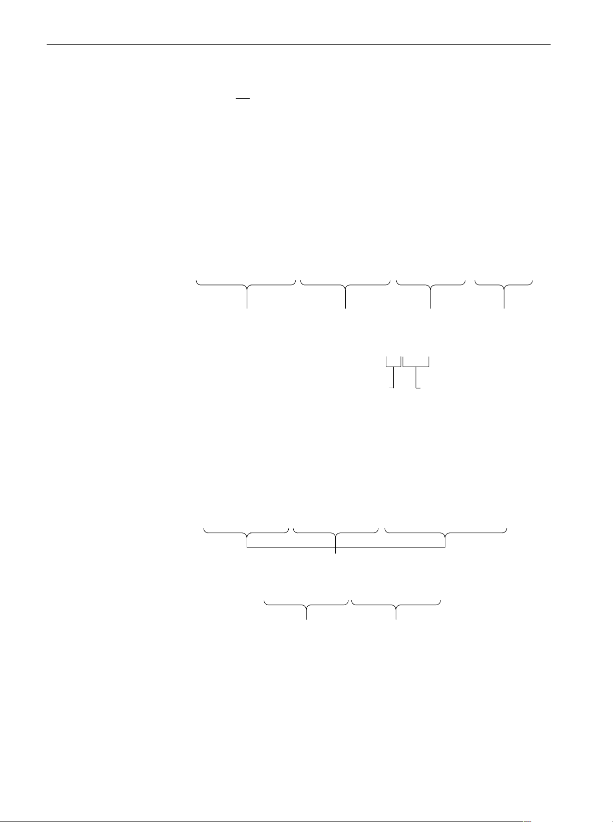
The Syntax and Commands chapter describes the structure and content of the
messages your program sends to the analyzer, Figure 1–1 shows command parts
as described in the Command Syntax subsection.
Command Parts
Header
Arguments
:Util3:PeakHoldĂĂActive,100,0,D1
Mnemonics
Figure 1-1: Common message elements
Chapter 2 also describes the effect of each command and provides examples of
how you might use it. The Command Groups section provides a list by functional area. The command description sections starting from the Configuration
Commands on page 2–37 arrange commands alphabetically for each command
group (see Figure 1–2).
Space
Comma
Waveform View Commands
Utility
Configuration Commands
Commands grouped in functional areas Commands listed alphabetically
Setup Commands
:Config:Block
:Config:Continue
:Config:Label
:Config:Message
:Config:Mode
and
Figure 1-2: Functional groupings and an alphabetical list of commands
1-2
3066 & 3086 3 GHz Real Time Spectrum Analyzer Programmer Manual
:Setup:FFTPoints
:Setup:CenterFrequency
:Setup:BlockSize
Syntax: . . .
Argument: . . .
Examples: . . .
for each command group
Getting Started
Status and Events
The program may request information from the analyzer. The analyzer provides
information in the form of status and error messages. Figure 1–3 illustrates the
basic operation of this system.
The Status and Events chapter starting on page 3–1 describes how to obtain
status and event messages in your programs.
Your program requests
status and event reports.
Controller
The analyzer sends status and
event reports.
3066/3086
Figure 1-3: Event (interrupt) driven programs
Programming Examples
The Programming Examples chapter starting on page 4–1 describes some
example programs of the PERL source codes (PERL is a freeware).
#
# Main
#
tcp_client(S, '', '3000');
tcp_client(SS, '', '3001');
print S "NewLine LF\n";
print S "Config:Pause On\n";
print S "Config:View1 Waveform\n";
print S "View1:Trace2:Source D1\n";
Figure 1-4: Example programs of the PERL source codes
3066 & 3086 3 GHz Real Time Spectrum Analyzer Programmer Manual
1-3
Getting Started
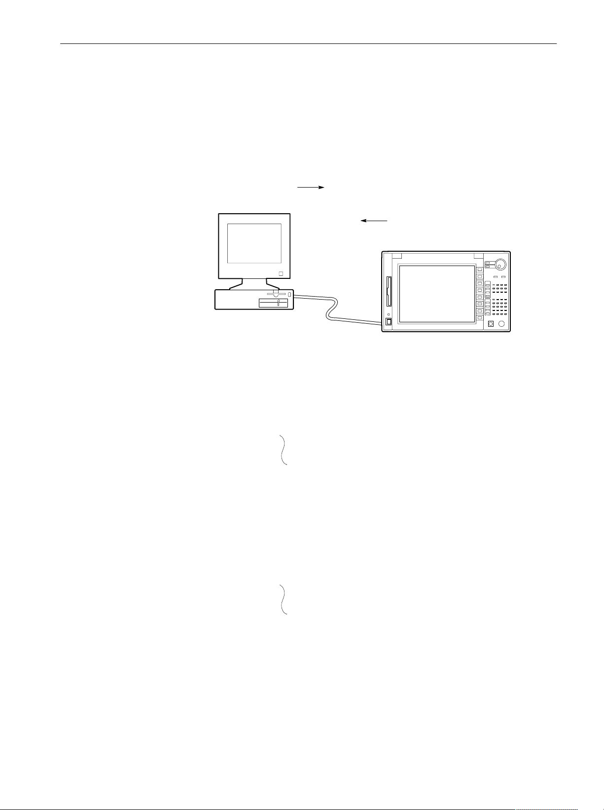
Connecting the Interface
The analyzer has an IBM PC based expansion slots on its rear panel, as shown in
Figure 1–5. The analyzer is shipped standard with a GPIB port. In addition, the
analyzer can be configured with optional networking cards.
H GPIB interface
H Ethernet interface (Option 10)
NOTE. Only a service personnel can install the network card. Contact Tektronix
for details.
You can also connect the following peripheral devices to the analyzer. Refer to
the 3066 and 3086 User Manual for information on using these interfaces.
This connector has a D-type shell and conforms to IEEE Std 488.1–1987
(The cable is available from Tektronix as part number 012–0991–00).
With Option 10, you can connect the analyzer directly to an Ethernet
network using a twisted pair (10BASE-T/100BASE-TX) cable.
H Mouse and keyboard interface
H Parallel interface for connecting a printer
H SCSI interface for connecting a SCSI device such as an hard disk.
Parallel connector
SCSI connector
1-4
Ethernet interface (Option 10)
GPIB interface
Mouse and keyboard interface
Figure 1-5: Interface connector location on the rear panel
3066 & 3086 3 GHz Real Time Spectrum Analyzer Programmer Manual
Using Communication Ports
The analyzer can communicate with the external controller or other devices on
the GPIB and Ethernet network.
Getting Started
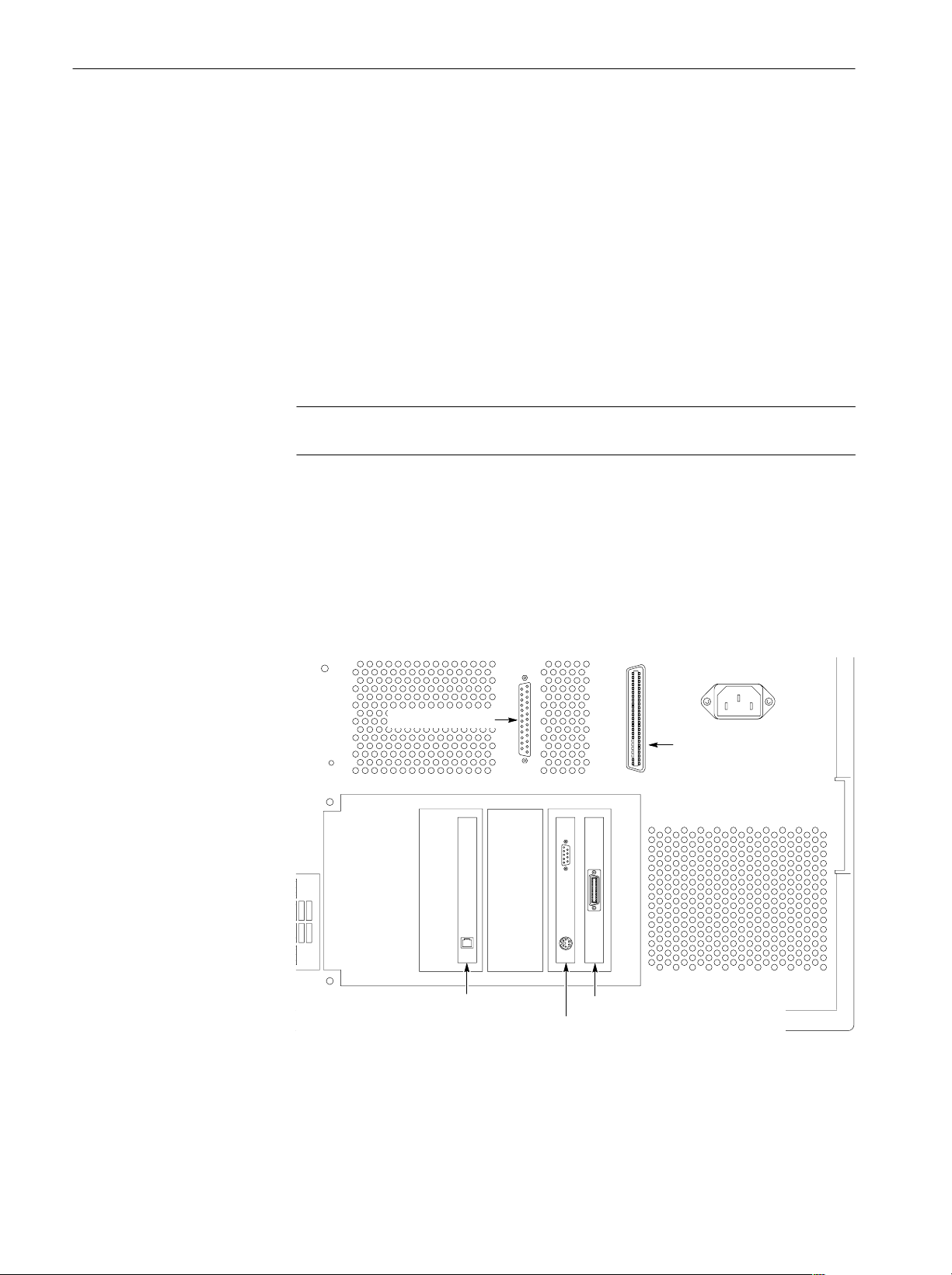
Using the GPIB
The analyzer has the Talker/Listener and Controller functions. Refer to the next
section about setting the parameters for the port.
Controller
3066/3086 as the Controller
Bus Bus
OR
Other GPIB device
3066/3086 as the Talker/Listner
Figure 1-6: GPIB connection
GPIB Device
GPIB Device
GPIB Device
GPIB Device
Figure 1-7: Typical GPIB network configurations
3066 & 3086 3 GHz Real Time Spectrum Analyzer Programmer Manual
GPIB Device
GPIB Device
GPIB Device
1-5

Getting Started
GPIB Requirements. Observe these rules when you use your analyzer with a
GPIB network:
H Assign a unique device address to each device on the bus. No two devices
can share the same device address.
H Do not connect more than 15 devices to any one bus.
H Connect one device for every 2 meters (6 feet) of cable used.
H Do not use more than 20 meters (65 feet) of cable to connect devices to a
bus.
H Turn on at least two-thirds of the devices on the network while using the
network.
H Connect the devices on the network in a star or linear configuration. Do not
use loop or parallel configurations (see Figure 1–7).
Using TCP/IP
The analyzer communicates with the external devices through the following two
ports on the TCP/IP Ethernet network.
H Command port receives commands from, or returns responses to the
external controller.
H Event port sends events to the external controller.
Refer to the next section about setting the parameters for these ports.
Controller
Command
port
TCP/IP Ethernet network
3066/3086
Event
port
1-6
Figure 1-8: Ethernet connection
3066 & 3086 3 GHz Real Time Spectrum Analyzer Programmer Manual
Setting Communication Parameters from the Front Panel
You can set the communication parameters from the front panel menu or with the
Remote commands. This section describes the front panel operation procedures.
For the remote control commands, refer to Remote Commands on page 2–381.
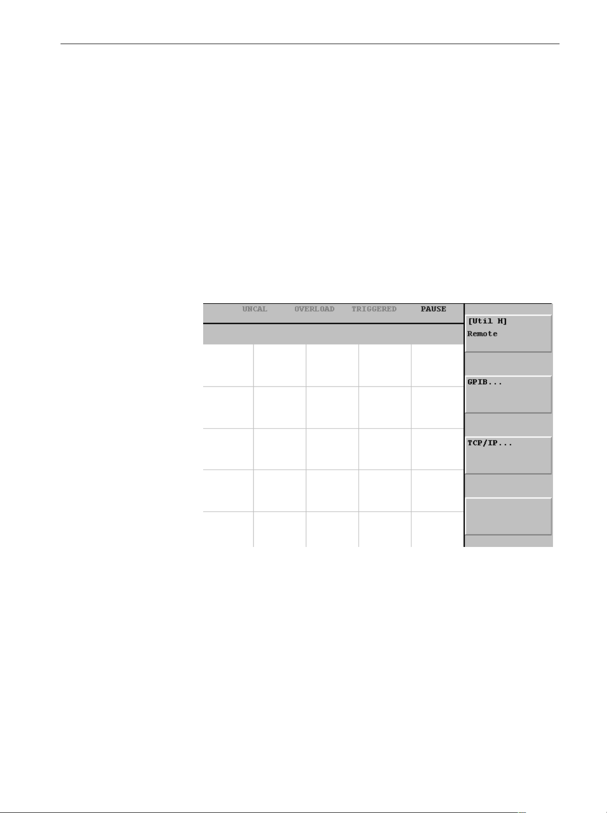
1. Press the CONFIG:UTILITY key to display the Utility menu.
2. Press the MORE... side key.
3. Press the UTIL H side key to display the Remote menu. See Figure 1–9.
H If you use the GPIB interface, go to the next section Setting the GPIB
Parameters on page 1–8.
H If you use the TCP/IP interface, go to the section Setting the TCP/IP
Parameters on page 1–9.
Getting Started
Figure 1-9: Setting the communication parameters
3066 & 3086 3 GHz Real Time Spectrum Analyzer Programmer Manual
1-7
Getting Started
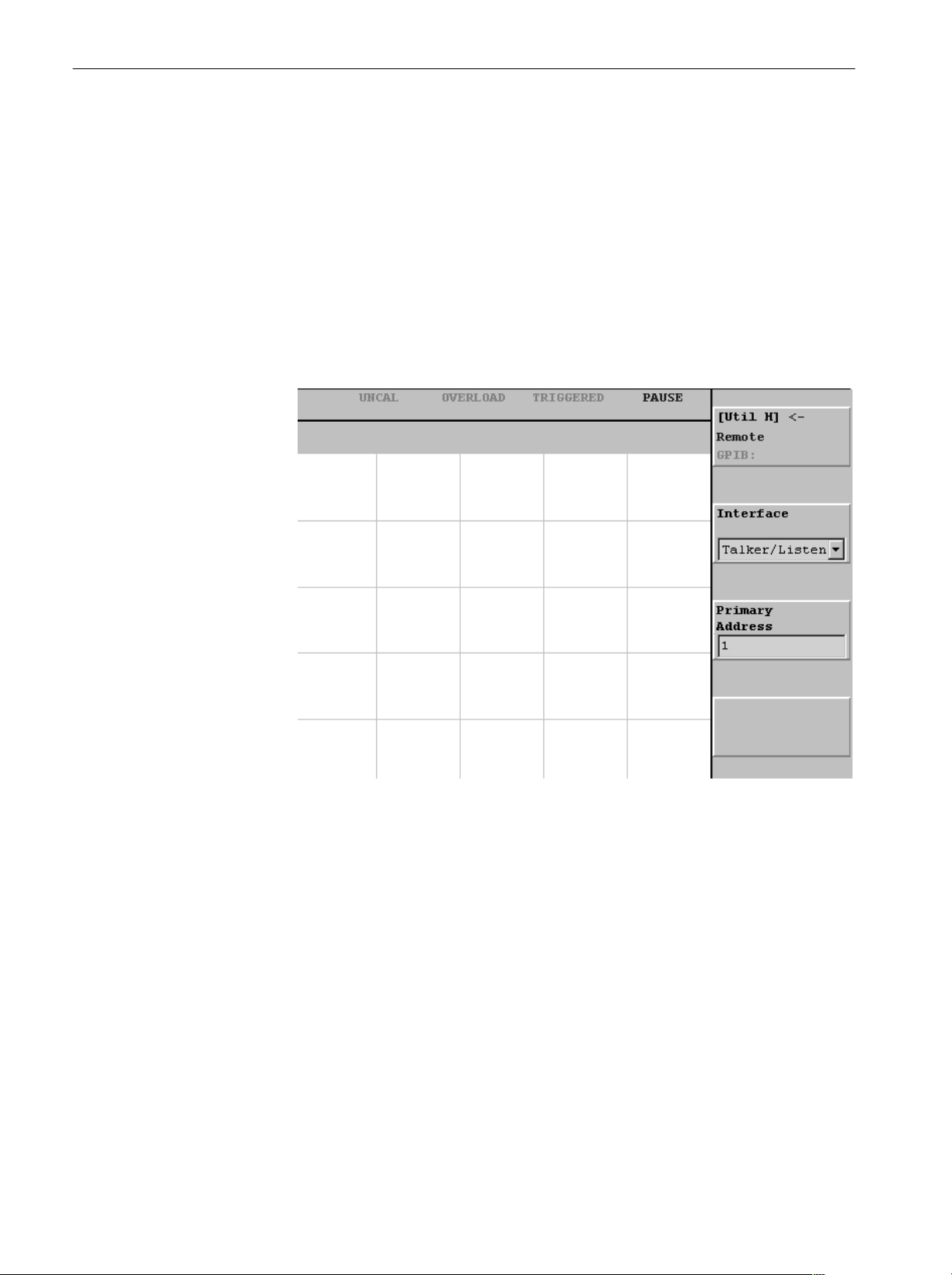
Setting the GPIB
Parameters
You need to set the GPIB parameters of the analyzer to match the configuration
of the bus. Once you have set these parameters, you can control the analyzer
through the GPIB interface.
1. Press the GPIB side key to display the GPIB configuration menu.
See Figure 1–10.
2. Press the Interface side key, and select Talker/Listener using either the
general purpose knob or the keypad.
3. Press the Primary Address side key, and set GPIB address using either the
general purpose knob or the keypad.
1-8
Figure 1-10: Setting the GPIB parameters
The analyzer is set up for bidirectional communication with your controller. If
you wish to isolate the analyzer from the bus:
H Press the Interface side key, and select Off using either the general purpose
knob or the keypad.
3066 & 3086 3 GHz Real Time Spectrum Analyzer Programmer Manual
Getting Started
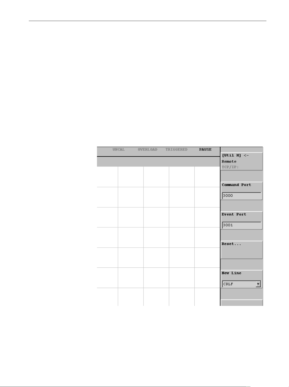
Setting the TCP/IP
Parameters
You need to set the TCP/IP parameters of the analyzer to match the network
configuration. Once you have set these parameters, you can control the analyzer
on the Ethernet network.
1. Press the TCP/IP side key to display the TCP/IP configuration menu.
See Figure 1–11.
2. Press the Command Port side key, and set the command port number using
either the general purpose knob or the keypad. The number ranges 1024 to
32767.
3. Press the Event Port side key, and set the event port number using either the
general purpose knob or the keypad. The number ranges 1024 to 32767. It
must be different from the command port number.
4. Press the New Line side key, and select the new-line character of returned
value using either the general purpose knob or the keypad.
Figure 1-11: Setting the TCP/IP parameters
3066 & 3086 3 GHz Real Time Spectrum Analyzer Programmer Manual
1-9

Getting Started
1-10
3066 & 3086 3 GHz Real Time Spectrum Analyzer Programmer Manual

Syntax and Commands


Command Syntax
This section contains general information on command structure and syntax
usage. You should familiarize yourself with this material before using the
analyzer command descriptions.
This manual describes commands and queries using the Backus-Naur Form
(BNF) notation. Table 2–1 defines the standard BNF symbols.
Table 2-1: BNF symbols and meanings
Symbol Meaning
<ą> Defined element
::= Is defined as
| Exclusive OR
{ą} Group; one element is required
[ą] Optional; can be omitted
.ă.Ă. Previous element(s) may be repeated
(ą) Comment
3066 & 3086 3 GHz Real Time Spectrum Analyzer Programmer Manual
2-1

Command Syntax
Commands and Queries
The analyzer commands are based on a hierarchical or tree structure (see Figure
2–1) that represents a subsystem. The top level of the tree is the root node; it is
followed by one or more lower-level nodes.
Creating Commands
View1
Marker
DeltaX
PeakX
Root node
LowerĆlevel
nodes
Figure 2-1: Example of subsystem hierarchy tree
You can create commands and queries from these subsystem hierarchy trees.
Commands specify actions for the instrument to perform. Queries return
measurement data and information about parameter settings.
The analyzer commands are created by stringing together the nodes of a
subsystem hierarchy and separating each node by a colon (:).
In Figure 2–1, View1 is the root node and Marker, X, DeltaX, and Peak are
lower-level nodes. To create a command, start with the root node View1 and
move down the tree structure adding nodes until you reach the end of a branch.
Most commands and some queries have parameters; you must include a value for
these parameters. The command descriptions, which start on page 2–7, list the
valid values for all parameters.
2-2
Creating Queries
For example, :View1:Marker:X 1.5 is a valid command created from the
hierarchy tree in Figure 2–1.
NOTE. If you specify a parameter value that is out of range, the parameter will
be set to a default value.
To create a query, start at the root node of a tree structure, move down to the end
of a branch, and add a question mark. :View1:Marker:X? is an example of a
valid query using the hierarchy tree in Figure 2–1.
3066 & 3086 3 GHz Real Time Spectrum Analyzer Programmer Manual
Command Syntax
Headers in Query
Responses
Parameter Types
You can control whether the analyzer returns headers as part of the query
response. Use the [:Util8]:Header command (page 2–386) to control this
feature. If header is on, the query response returns command headers and formats
itself as a valid set command. When header is off, the response includes only the
values. This may make it easier to parse and extract the information from the
response. Table 2–2 shows the difference in responses.
Table 2-2: Comparison of header off and on responses
Query Header off response Header on response
:View1:Source? "FILE1.AP" :View1:Source "File1.AP"
:Setup:Span? 5M :Setup:Span 5M
Parameters are indicated by angle brackets, such as <file_name>. There are
several different types of parameters, as listed in Table 2–3. The parameter type
is listed after the parameter. Some parameter types are defined specifically for
the analyzer command set and some are defined by ANSI/IEEE 488.2-1987.
Table 2-3: Parameter types used in syntax descriptions
Special Characters
Parameter Type Description Example
boolean Boolean numbers or values On, Off
discrete A list of specific values MIN, MAX
NR11numeric Integers 0, 1, 15, -1
NR21numeric Decimal numbers 1.2, 3.141516, -6.5
NR31numeric Floating point numbers 3.1415E-9, -16.1E5
NRf1numeric Flexible decimal number that
may be type NR1, NR2, or NR3
2
string
1 An ANSI/IEEE 488.2Ć1992Ćdefined parameter type.
2 Defined in ANSI/IEEE 488.2 as String Response Data" and String Program Data."
Alphanumeric characters (must
be within quotation marks)
See NR1, NR2, NR3 examples
Testing 1, 2, 3"
The Line Feed (LF) character (ASCII 10) and all characters in the range of
ASCII 127-255 are defined as special characters. Using these characters in any
command yields unpredictable results.
3066 & 3086 3 GHz Real Time Spectrum Analyzer Programmer Manual
2-3
Command Syntax
Abbreviating Commands,
Queries, and Parameters
Chaining Commands and
Queries
You must not
abbreviate all commands, queries, and parameters. For example,
shortening the command :Setup:CenterFrequency to :Setup:CenterFreq
causes an error.
You can chain several commands or queries together into a single message. To
create a chained message, first create a command or query, then add a semicolon
(;), and finally add more commands or queries and semicolons until you are
done. If the command following a semicolon is a root node, precede it with a
colon (:). Figure 2–2 illustrates a chained message consisting of several
commands and queries. The chained message should end in a command or query,
not a semicolon. Responses to any queries in your message are separated by
semicolons.
:Config:Setup Standard;:Setup:BlockSize 200;:View1:Marker:X?;:Util2:Source?
First command Second command Second query
The response from this chained message might be:
First query
1.2;Active
Response from first query Response from second query
Figure 2-2: Example of chaining commands and queries
If a command or query has the same root and lower-level nodes as the previous
command or query, you can omit these nodes. In Figure 2–3, the second
command has the same root node (Marker) as the first command, so these nodes
can be omitted.
:View1:Marker:X 1.5;:View1:Marker:Y -20;:View1:Marker:DeltaMarker On
Identical root and lowerĆlevel nodes
:View1:Marker:X 1.5;Y -20;DeltaMarker On
First command Additional commands
(omitted the root nodes)
Figure 2-3: Example of omitting root and lowerĆlevel nodes in a chained message
2-4
3066 & 3086 3 GHz Real Time Spectrum Analyzer Programmer Manual

Command Syntax
Unit and SI Prefix
General Rules
If a decimal numeric argument refers to amplitude, frequency, or time, you can
express it using SI units instead of the scaled explicit point input value format
<NR3>. (SI units conform to the Systeme International d’Unites standard.) For
example, you can use the input format 200 m or 1.0 M instead of 200.0E–3 or
1.0E+6, respectively, to specify the argument.
NOTE. You must omit the unit, such as Hz and dB. For example, 5 MHz of
frequency is represented by “5M” in a command.
The SI prefixes, which must be included, are shown below. Note that either
lower or upper case prefixes can be used.
SI prefix p/P n/N u/U m/M k/K m/M g/G
Corresponding power 10
* Note that the prefix m/M indicates 10-3when the decimal numeric argument denotes
amplitude or time, but 10
-12
6
when it denotes frequency.
10
-9
10
-6
10
-3
10
3
10
6
10
9
Here are three general rules for using the analyzer commands, queries, and
parameters:
H You must use double (“ ”) quotation marks for quoted strings.
correct: “This string uses quotation marks correctly.”
incorrect: ‘This string also uses quotation marks correctly.’
incorrect: “This string does not use quotation marks correctly.’
H You can use upper case, lower case, or a mixture of both cases for all
commands, queries, and parameters.
:VIEW1:MASK:RBW1M:FREQUENCYĂ25M
is the same as
:view1:mask:rbw1m:frequencyĂ25m
and
:view1:mask:rbw1m:FREQUENCYĂ25M
H No embedded spaces are allowed between or within nodes.
correct: :VIEW1:MASK:RBW1M:FREQUENCYĂ25M
incorrect: :VIEW1: MASK: RBW1M: FREQ UENCYĂ25M
3066 & 3086 3 GHz Real Time Spectrum Analyzer Programmer Manual
2-5

Command Syntax
Constructed Mnemonics
Some header mnemonics specify one of a range of mnemonics. For example, a
view mnemonic can be either View1, View2, ... or View8. You use these
mnemonics in the command just as you do any other mnemonic. For example,
there is a View1:Format command, and there is also a View2:Format command.
In the command descriptions, this list of choices is abbreviated as View<x>.
Table 2-4: Constructed mnemonics
Symbol Meaning
View<x> A view specifier where <x>=1to8,corresponding toA-H
Utility<x> A utility specifier where <x>=1to8,corresponding toA-H
Dev<x> A GPIB device where <x> is the GPIB address
Result<x> A result specifier whrere <x> ranges 1 to 26, depending on commands
<address> GPIB address, ranging 1 to 30
<command> IEEE 488.2 command e.g. *IDN
<message> Specify the message for the command
<item> Specify the item for the command
2-6
3066 & 3086 3 GHz Real Time Spectrum Analyzer Programmer Manual

Command Groups
The following sections list the 3066 and 3086 spectrum analyzer commands in
two ways. They first present them by functional groups, then list them alphabetically. The functional group lists start below. The alphabetical lists provide more
detail on each command and start on page 2–37.
Items followed by question marks are queries; items without question marks are
commands. Some items in this section have a question mark in parentheses (?) in
the command header section; this indicates that the item can be both a command
and a query.
3066 & 3086 3 GHz Real Time Spectrum Analyzer Programmer Manual
2-7

Command Groups
Functional Groups
There are four main groups:
H Configuration command group configures the analyzer for the specific
measurement. Also, it starts or stops data acquisition.
H Setup command group sets up the analyzer hardware, such as frequency,
span, trigger, and memory.
H View command group displays waveform and performs measurement.
H Utility command group controls the utilities, such as self calibration, file
management, averaging, and remote operation.
Table 2–5 lists the functional groups and subgroups of the commands. The
analyzer has its system program modules corresponding to each subgroup.
2-8
3066 & 3086 3 GHz Real Time Spectrum Analyzer Programmer Manual

Command Groups
Table 2-5: Functional groups in the command set
Group Subgroup Description
Configuration - Configure the analyzer and start/stop acquisition
Setup
View
Standard Set up the analyzer for the standard measurement
CDMA Set up the analyzer for the CDMA measurement
Waveform Control the Waveform view
Analog Control the Analog view
FSK Control the FSK view
Spectrogram Control the Spectrogram view
Waterfall Control the Waterfall view
Polar Control the Polar view
Eye diagram Control the Eye diagram view
Symbol table Control the Symbol table view
EVM Control the EVM view
CDMA Waveform Control the CDMA Waveform view
CDMA Polar Control the CDMA Polar view
CDMA Time Control the CDMA Time view
CodeSpectrogram
1
Control the codeĆdomain spectrogram view
(cdmaOne standard)
CodePolar
CodePower
1
Control the polar view (cdmaOne standard)
1
Control the codeĆdomain power view
(cdmaOne standard)
CodeWSpectrogram
2
Control the codeĆdomain spectrogram view
(WĆCDMA standard)
CodeWPolar
CodeWPower
2
Control the polar view (WĆCDMA standard)
2
Control the codeĆdomain power view
(WĆCDMA standard)
CCDF
CCDFView
3
Control the CCDF measurement
3
Control the CCDF view
Utility
Self gainĆcalibration Control the self gainĆcalibration
Save/Load Control to save and load data to/from files
Average Control averaging
Remote Control remote operation
1
3066 option 15 and 3086 option 16 only.
2
3086 option 16 only.
3
3066/3086 option 20 only.
3066 & 3086 3 GHz Real Time Spectrum Analyzer Programmer Manual
2-9

Command Groups
General Programming Sequence
The programs for controlling the analyzer have the following steps in general:
1. Configuration: Use the Configuration command group to set the basic
operation mode and assign the Views.
Also, use the Remote command subgroup (Util8) to set the communication
parameters with other device.
2. Setup: Use the Setup command group to set the hardware, such as frequency,
span, trigger, and memory.
3. Acquisition: Use the Configuration command group to start or stop the
waveform acquisition.
You can load previously acquired data with the Save/Load command
subgroup (Util2).
4. Measurement and Display: Use the View command group to measure and
display the result. For example, if you have selected the Spectrogram View
in the configuration, use the Spectrogram View command subgroup.
You can use the Average command subgroup (Util3) to average waveforms.
Also, you can save the data to a file with the Save/Load command subgroup
(Util2).
Section 4, Programming Examples shows some example programs.
Powering on the analyzer initializes its settings to the factory defaults. For the
details about the factory defaults, refer to Appendix B: Factory Initialization
Settings.
2-10
3066 & 3086 3 GHz Real Time Spectrum Analyzer Programmer Manual

Configuration Commands
These commands configure the system. These commands are equivalent to the
CONFIG and START/STOP menu on the front panel.
Table 2-6: Configuration commands
Header Description
:Config:Block Start or stop data acquisition in the Block mode
:Config:Continue Continue the data acquisition
:Config:Label Display a label on the screen
:Config:Message Display a message in red on the screen
:Config:Mode Load settings from the basic configuration file
:Config:Mode:Load Load settings from a file saved before
:Config:Mode:Save Save settings to a file
:Config:Next Stop and restart a block data acquisition
Command Groups
:Config:Pause (?) Pause the data acquisition on each block
:Config:PrintScreen Print a screen image to a printer
:Config:PrintScreen:Printer (?) Specify the printer to print screen images
:Config:PrintScreen:Items? Return the list of available printers
:Config:PrintScreen:Save Save a screen image to a file
:Config:Roll Start or stop the data acquisition in the Roll mode
:Config:Setup (?) Load the Setup program for the SETUP menu
:Config:Setup:Items? Return the list of available programs for the setup
:Config:Setup:Show Display the CONFIG:SETUP menu
:Config:Start Start a data acquisition in the Block mode
:Config:StartAgain Stop and restart the acquisition in the Block mode
:Config:Status:Overload? Query the overload status of the A/D converter
:Config:Status:Pause? Query if the data acquisition pauses
:Config:Status:Triggered? Query if the analyzer is triggered
:Config:Status:Uncal? Query if the analyzer is uncalibrated
:Config:Stop Stop the data acquisition
:Config:System? Query the instrument name
:Config:Util:Items? Return the list of available programs for the utility
:Config:Util<x> (?) Assign the Utility program to a Utility side key
:Config:Util<x>:Show Display the CONFIG:UTILITY menu
:Config:Version? Query the version of the Configuration program
3066 & 3086 3 GHz Real Time Spectrum Analyzer Programmer Manual
2-11

Command Groups
Setup Commands
Table 2-6: Configuration commands (Cont.)
Header Description
:Config:View:BackgroundColor (?) Select the background color for waveform view area
:Config:View:Items? Return the list of available programs for the view
:Config:View:MarkerLink (?) Determine whether the markers in different views
move in unison or separately
:Config:View:Style (?) Select the view layout
:Config:View<x> (?) Assign the View program to a View side key
:Config:View<x>:Show Display the View menu
Standard Setup
Commands
When you select Standard in the Config:Setup command, use the following
commands to control parameters for the standard measurement.
These commands are equivalent to the SETUP menu on the front panel.
Table 2-7: Standard Setup commands
Header Description
:Setup:BlockSize (?) Set the number of frames per block
:Setup:CenterFrequency (?) Set the center frequency
:Setup:FFTPoints (?) Set the number of FFT sampling points per frame
:Setup:FFTWindow (?) Select the FFT window
:Setup:FramePeriod (?) Set the frame period in the Block mode
:Setup:FrequencyOffset (?) Set the frequency display offset
:Setup:InputCoupling (?) Select the input coupling to the RF input
:Setup:InputMode (?) Select the signal input mode
:Setup:LevelOffset (?) Set the level display offset
:Setup:Load Load a trigger mask from a file
:Setup:MarkerToFreq Set the center frequency to the value at the marker
:Setup:MaxSpan Set the span to the maximum
2-12
:Setup:MemoryMode (?) Select the memory mode
:Setup:ReferenceLevel (?) Set the reference level
:Setup:ReferenceOsc (?) Select the reference oscillator
:Setup:Save Save a trigger mask to a file
3066 & 3086 3 GHz Real Time Spectrum Analyzer Programmer Manual

Command Groups
Table 2-7: Standard Setup commands (Cont.)
Header Description
:Setup:Span (?) Select the span
:Setup:Trigger (?) Select the trigger mode
:Setup:TriggerCount (?) Turn the trigger counter on or off
:Setup:TriggerDelayed (?) Set the delay time in the Delayed trigger mode
:Setup:TriggerDomain (?) Select the trigger domain
:Setup:TriggerInterval (?) Set the time interval in the Interval trigger mode
:Setup:TriggerPosition (?) Set the trigger position
:Setup:TriggerSlope (?) Select the trigger slope
:Setup:TriggerSource (?) Select the trigger source
:Setup:TriggerTimeout (?) Set the timeout in the Timeout trigger mode
:Setup:TriggerTimes (?) Set the trigger count in the Count trigger mode
:Setup:Version? Query the version of the Setup program
CDMA Setup Commands
:Setup:Zoom:Execute Expand the waveform
:Setup:Zoom:Frequency (?) Set the center frequency for zooming
:Setup:Zoom:Mag (?) Select the magnification factor for zooming
When you select CDMA in the Config:Setup command, use the following
commands to control parameters for the CDMA measurement.
These commands are equivalent to the SETUP menu on the front panel.
Table 2-8: CDMA Setup commands
Header Description
:Setup:BlockSize (?) Set the number of frames per block
:Setup:CDMA:Channel (?) Select the channel
:Setup:CDMA:Span30M Set the span to 30 MHz
:Setup:CDMA:Span50M Set the span to 50 MHz
:Setup:CDMA:Span5MAuto Set the span to 5 MHz and the trigger mode to
Auto
:Setup:CDMA:Span5MNormal Set the span to 5 MHz and the trigger mode to
Normal
:Setup:CDMA:Standard (?) Select the CDMA standard
:Setup:CDMA:TriggerLevel (?) Set the trigger mask level in the time domain
:Setup:MarkerToFreq Set the center frequency to the value at the marker
3066 & 3086 3 GHz Real Time Spectrum Analyzer Programmer Manual
2-13

Command Groups
Table 2-8: CDMA Setup commands (Cont.)
Header Description
:Setup:MaxSpan Set the span to the maximum
:Setup:ReferenceLevel (?) Set the reference level
:Setup:ReferenceOsc (?) Select the reference oscillator
:Setup:Span (?) Select the span
:Setup:Trigger (?) Select the trigger mode
:Setup:TriggerCount (?) Turn the trigger counter on or off
:Setup:TriggerDelayed (?) Set the delay time in the Delayed trigger mode
:Setup:TriggerDomain (?) Select the trigger domain
:Setup:TriggerInterval (?) Set the time interval in the Interval trigger mode
:Setup:TriggerPosition (?) Set the trigger position in a block
:Setup:TriggerSlope (?) Select the trigger slope
:Setup:TriggerSource (?) Select the trigger source
View Commands
Waveform View
Commands
:Setup:TriggerTimeout (?) Set the timeout in the Timeout trigger mode
:Setup:TriggerTimes (?) Set the trigger count in the Count trigger mode
:Setup:Version? Query the version of the CDMA Setup program
These commands control the Waveform view.
Table 2-9: Waveform View commands
Header Description
:View<x>:Average:Times (?) Set the number of frames for averaging
:View<x>:Average:Type (?) Select the average type
:View<x>:Compression (?) Select the way to compress data for displaying
:View<x>:CopyFrom Copy display data from a text file to the data register
:View<x>:CopyTo Copy display data to a file or data register
:View<x>:Edit (?) Determine whether or not to display the trigger mask
2-14
:View<x>:Edit:DrawHorizontal Draw the entire trigger mask line horizontally through
the marker
:View<x>:Edit:DrawLine Draw the trigger mask line between the marker and
the delta marker
3066 & 3086 3 GHz Real Time Spectrum Analyzer Programmer Manual

Command Groups
Table 2-9: Waveform View commands (Cont.)
Header Description
:View<x>:Edit:DrawMax Draw the entire trigger mask line horizontally at the
maximum level
:View<x>:Edit:DrawMin Draw the entire trigger mask line horizontally at the
minimum level
:View<x>:Edit:Y (?) Set the vertical position of the marker in editing the
trigger mask
:View<x>:Format (?) Select the waveform display format
:View<x>:Marker:Band:Center (?) Set the center frequency of the band marker
:View<x>:Marker:Band:Left (?) Set the left side frequency of the band marker
:View<x>:Marker:Band:Right (?) Set the right side frequency of the band marker
:View<x>:Marker:Band:Width (?) Set the bandwidth of the band marker
:View<x>:Marker:DeltaMarker (?) Turn on or off the delta marker
:View<x>:Marker:DeltaX (?) Set the horizontal position of the delta marker
:View<x>:Marker:DeltaY? Query the vertical position of the delta marker
:View<x>:Marker:Peak Move the marker to the adjacent peak
:View<x>:Marker:ResetDelta Move the delta marker to the marker position
:View<x>:Marker:SearchMax Search the maximum peak and place the marker on it
:View<x>:Marker:SearchMin Search the minimum peak and place the marker on it
:View<x>:Marker:SearchSeparation (?) Set the resolution to separate two peaks
:View<x>:Marker:Trace (?) Select the trace on which the markers are placed
:View<x>:Marker:X (?) Set the horizontal position of the marker
:View<x>:Marker:Y? Query the vertical position of the marker
:View<x>:MaskVisible (?) Specify whether or not to display the trigger mask
:View<x>:Measurement (?) Select the measurement item
:View<x>:Measurement:ACP:BW (?) Set the bandwidth for the ACP measurement
:View<x>:Measurement:ACP:Marker
(?)
:View<x>:Measurement:ACP:SP (?) Set the frequency interval between adjacent channels
:View<x>:Measurement:OBW (?) Set the occupied bandwidth
:View<x>:Position (?) Set the display position in a block
Select the marker position for the ACP measurement
for the ACP measurement
:View<x>:Result<y>? Query the measurement results
:View<x>:Scale:AutoScale Scale the vertical axis automatically
:View<x>:Scale:HoldYScale (?) Determine whether to hold or reset the vertical scale
when you change the input source
3066 & 3086 3 GHz Real Time Spectrum Analyzer Programmer Manual
2-15

Command Groups
Table 2-9: Waveform View commands (Cont.)
Header Description
:View<x>:Scale:XScale (?) Scale the horizontal axis
:View<x>:Scale:XStart (?) Set the start point of the horizontal axis on the screen
:View<x>:Scale:YScale (?) Scale the vertical axis
:View<x>:Scale:YStart (?) Set the start point of the vertical axis on the screen
:View<x>:Source (?) Select the input data source
:View<x>:Trace2:Compression (?) Select the compression method to display the trace 2
:View<x>:Trace2:Format (?) Select the display format of the trace 2
:View<x>:Trace2:Source (?) Select the input data source of the trace 2
:View<x>:Trace2:Z (?) Set the frame number of the trace 2
:View<x>:Version? Query the version of the Waveform View program
:View<x>:Z (?) Set the frame number
Analog View Commands
These commands control the Analog view to analyze an analog modulating
signal. This view is capable of demodulating and displaying PM (Phase
Modulation), AM (Amplitude Modulation), or FM (Frequency Modulation)
signals.
Table 2-10: Analog View commands
Header Description
:View<x>:CopyTo Copy display data to a file or data register
:View<x>:Format (?) Select the waveform display format
:View<x>:Marker:DeltaMarker (?) Turns on or off the delta marker
:View<x>:Marker:DeltaX (?) Query the horizontal position of the delta marker
:View<x>:Marker:DeltaY? Query the vertical position of the delta marker
:View<x>:Marker:Peak Move the marker to the adjacent peak
:View<x>:Marker:ResetDelta Move the delta marker to the marker position
:View<x>:Marker:SearchMax Search the maximum peak and place the marker on it
:View<x>:Marker:SearchMin Search the minimum peak and place the marker on it
:View<x>:Marker:SearchSeparation (?) Set the resolution to separate two peaks
:View<x>:Marker:X (?) Set the horizontal position of the marker
2-16
:View<x>:Marker:Y? Query the vertical position of the marker
:View<x>:Scale:AutoScale Scale the vertical axis automatically
3066 & 3086 3 GHz Real Time Spectrum Analyzer Programmer Manual

Command Groups
Table 2-10: Analog View commands (Cont.)
Header Description
:View<x>:Scale:HoldYScale (?) Determine whether to hold or reset the vertical scale
when you change the input source
:View<x>:Scale:XScale (?) Scale the horizontal axis
:View<x>:Scale:XStart (?) Set the start point of the horizontal axis on the screen
:View<x>:Scale:YScale (?) Scale the vertical axis
:View<x>:Scale:YStart (?) Set the start point of the vertical axis on the screen
:View<x>:Source (?) Select the input data source
:View<x>:Version? Query the version of the Analog View program
:View<x>:Z (?) Set the frame number
FSK View Commands
These commands control the FSK view. In this view, the FSK (Frequency Shift
Keying) signal is demodulated and displayed.
Table 2-11: FSK View commands
Header Description
:View<x>:CopyTo Copy display data to a file or data register
:View<x>:Marker:DeltaMarker (?) Turns on or off the delta marker
:View<x>:Marker:DeltaX (?) Set the horizontal position of the delta marker
:View<x>:Marker:DeltaY? Query the vertical position of the delta marker
:View<x>:Marker:Peak Move the marker to the adjacent peak
:View<x>:Marker:ResetDelta Move the delta marker to the marker position
:View<x>:Marker:SearchMax Search the maximum peak and place the marker on it
:View<x>:Marker:SearchMin Search the minimum peak and place the marker on it
:View<x>:Marker:SearchSeparation (?) Set the resolution to separate two peaks
:View<x>:Marker:X (?) Set the horizontal position of the marker
:View<x>:Marker:Y? Query the vertical position of the marker
:View<x>:Scale:AutoScale Scale the vertical axis automatically
:View<x>:Scale:HoldYScale (?) Determine whether to hold or reset the vertical scale
when you change the input source
:View<x>:Scale:XScale (?) Scale the horizontal axis
:View<x>:Scale:XStart (?) Set the start point of the horizontal axis on the screen
:View<x>:Scale:YScale (?) Scale the vertical axis
:View<x>:Scale:YStart (?) Set the start point of the vertical axis on the screen
3066 & 3086 3 GHz Real Time Spectrum Analyzer Programmer Manual
2-17

Command Groups
Table 2-11: FSK View commands (Cont.)
Header Description
:View<x>:Source (?) Select the input data source
:View<x>:Version? Query the version of the FSK View program
:View<x>:Z (?) Set the frame number
Spectrogram View
Commands
These commands control the Spectrogram view.
Table 2-12: Spectrogram View commands
Header Description
:View<x>:Compression (?) Select the way to compress data for displaying
:View<x>:Format (?) Select the waveform display format
:View<x>:Marker:DeltaMarker (?) Turn the delta marker on or off
:View<x>:Marker:DeltaT? Query the delta marker position on the time axis
:View<x>:Marker:DeltaX (?) Set the horizontal position of the delta marker
:View<x>:Marker:DeltaY? Query the vertical position of the delta marker
:View<x>:Marker:DeltaZ (?) Set the delta marker position on the Z axis
:View<x>:Marker:Peak Move the marker to the adjacent peak
:View<x>:Marker:ResetDelta Move the delta marker to the marker position
:View<x>:Marker:SearchMax Search the maximum peak and place the marker on it
:View<x>:Marker:SearchMin Search the minimum peak and place the marker on it
:View<x>:Marker:SearchSeparation (?) Set the resolution to separate two peaks
:View<x>:Marker:T? Query the marker position on the time axis
2-18
:View<x>:Marker:X (?) Set the horizontal position of the marker
:View<x>:Marker:Y? Query the vertical position of the marker
:View<x>:Marker:Z (?) Set the marker position on the Z axis
:View<x>:Monochrome (?) Set the display to monochrome
:View<x>:NumberColors (?) Select the number of display colors
:View<x>:Scale:AutoScale Scale the vertical axis automatically
:View<x>:Scale:HoldYScale (?) Determine whether to hold or reset the vertical scale
when you change the input source
:View<x>:Scale:XScale (?) Scale the horizontal axis
:View<x>:Scale:XStart (?) Set the start point of the horizontal axis on the screen
:View<x>:Scale:YScale (?) Scale the vertical axis
3066 & 3086 3 GHz Real Time Spectrum Analyzer Programmer Manual

Command Groups
Table 2-12: Spectrogram View commands (Cont.)
Header Description
:View<x>:Scale:YStart (?) Set the start point of the vertical axis on the screen
:View<x>:Scale:ZScale (?) Scale the Z axis
:View<x>:Scale:ZStart (?) Set the start point of the Z axis on the screen
:View<x>:Source (?) Select the input data source
:View<x>:Version? Query the version of the Spectrogram View program
:View<x>:ZGap (?) Set the interval between two frames on the Z axis
Waterfall View Commands
These commands control the Waterfall view.
Table 2-13: Waterfall View commands
Header Description
:View<x>:Compression (?) Select the way to compress data for displaying
:View<x>:Format (?) Select the waveform display format
:View<x>:Marker:DeltaMarker (?) Turn the delta marker on or off
:View<x>:Marker:DeltaT? Query the delta marker on the time axis
:View<x>:Marker:DeltaX (?) Set the horizontal position of the delta marker
:View<x>:Marker:DeltaY? Query the vertical position of the delta marker
:View<x>:Marker:DeltaZ (?) Set the delta marker position on the Z axis
:View<x>:Marker:Peak Move the marker to the adjacent peak
:View<x>:Marker:ResetDelta Move the delta marker to the marker position
:View<x>:Marker:SearchMax Search the maximum peak and place the marker on it
:View<x>:Marker:SearchMin Search the minimum peak and place the marker on it
:View<x>:Marker:SearchSeparation (?) Set the resolution to separate two peaks
:View<x>:Marker:T? Query the marker position on the time axis
:View<x>:Marker:X (?) Set the horizontal position of the marker
:View<x>:Marker:Y? Query the vertical position of the marker
:View<x>:Marker:Z (?) Set the marker position on the Z axis
:View<x>:Scale:AutoScale Scale the vertical axis automatically
:View<x>:Scale:HoldYScale (?) Determine whether to hold or reset the vertical scale
when you change the input source
:View<x>:Scale:XScale (?) Scale the horizontal axis
:View<x>:Scale:XStart (?) Set the start point of the horizontal axis on the screen
3066 & 3086 3 GHz Real Time Spectrum Analyzer Programmer Manual
2-19

Command Groups
Table 2-13: Waterfall View commands (Cont.)
Header Description
:View<x>:Scale:YScale (?) Scale the vertical axis
:View<x>:Scale:YStart (?) Set the start point of the vertical axis on the screen
:View<x>:Scale:ZScale (?) Scale the Z axis
:View<x>:Scale:ZStart (?) Set the start point of the Z axis on the screen
:View<x>:Source (?) Select the input data source
:View<x>:Version? Query the version of the Waterfall View program
:View<x>:YHeight (?) Specify the number of pixels of vertical fullĆscale
:View<x>:ZGap (?) Set interval between adjacent Z axes on the screen
Polar View Commands
These commands control the Polar view.
Table 2-14: Polar View commands
Header Description
:View<x>:AlphaBT (?) Set the a/BT
:View<x>:AutoCarrier (?) Turn on or off the carrier search function
:View<x>:Burst:BlockSize (?) Set the range for searching a burst
:View<x>:Burst:NumberFrames (?) Set the range for acquiring burst data
:View<x>:Burst:Offset (?) Set the start point for acquiring burst data
:View<x>:Burst:Search (?) Determine whether to search a burst
:View<x>:Burst:Threshold (?) Set the threshold to detect the rising edge of a burst
:View<x>:Carrier (?) Set the carrier frequency
:View<x>:Display (?) Select the display data source
:View<x>:Format (?) Select the waveform display format
:View<x>:Marker:A? Query the amplitude at the marker position
:View<x>:Marker:DeltaT (?) Set the delta marker position on the time axis
:View<x>:Marker:P? Query the phase at the marker position
2-20
:View<x>:Marker:T (?) Set the marker position on the time axis
:View<x>:Marker:X? Query the horizontal position of the marker
:View<x>:Marker:Y? Query the vertical position of the marker
:View<x>:MeasDestination (?) Select the data register to which the measurement
data is output
:View<x>:MeasFilter (?) Select the filter for the measurement data
3066 & 3086 3 GHz Real Time Spectrum Analyzer Programmer Manual

Command Groups
Table 2-14: Polar View commands (Cont.)
Header Description
:View<x>:Modulation (?) Select the modulation type
:View<x>:Position (?) Set display position in a block
:View<x>:RefDestination (?) Select the data register to which the reference data is
output
Eye Diagram View
Commands
:View<x>:RefFilter (?)
:View<x>:Result<y>? Query the measurement results
:View<x>:Source (?) Select the input data source
:View<x>:Standard:CDPD Set parameters according to the CDPD standard
:View<x>:Standard:GSM Set parameters according to the GSM standard
:View<x>:Standard:NADC Set parameters according to the NADC standard
:View<x>:Standard:PDC Set parameters according to the PDC standard
:View<x>:Standard:PHS Set parameters according to the PHS standard
:View<x>:Standard:TETRA Set parameters according to the TETRA standard
:View<x>:SymbolRate (?) Set the symbol rate
:View<x>:Version? Query the version of the Polar View program
:View<x>:Z (?) Set the frame number
Select the filter for the reference data
These commands control the Eye Diagram view.
Table 2-15: Eye Diagram View commands
Header Description
:View<x>:EyeLength (?) Set the number of symbols on the horizontal axis
:View<x>:Format (?) Select the waveform display format
:View<x>:Marker:T (?) Set the marker position on the time axis
:View<x>:Marker:Y? Query the vertical position of the marker
:View<x>:Source (?) Select the input data source
:View<x>:Version? Query the version of the Eye Diagram View program
3066 & 3086 3 GHz Real Time Spectrum Analyzer Programmer Manual
2-21

Command Groups
Symbol Table View
Commands
EVM View Commands
These commands control the Symbol Table view.
Table 2-16: Symbol Table View commands
Header Description
:View<x>:CopyTo Copy display data to the clipboard
:View<x>:Marker:Data? Query the value at the marker position
:View<x>:Marker:Symbol?
:View<x>:Marker:T (?) Set the marker position on the time axis
:View<x>:Radix (?) Select the radix to display the Symbol Table
:View<x>:Rotate (?) Set the reference phase
:View<x>:Source (?) Select the input data source
:View<x>:Symbol (?)
:View<x>:Version? Query the version of the Symbol Table View program
Query the symbol location where the marker is placed
Set the symbol location where the marker is placed
These commands control the EVM (Error Vector Magnitude) view.
Table 2-17: EVM View commands
Header Description
:View<x>:CopyTo Copy display data to a file or data register
:View<x>:Format (?) Select the waveform display format
:View<x>:Marker:DeltaMarker (?) Turn the delta marker on or off
:View<x>:Marker:DeltaX (?) Set the horizontal position of the delta marker
:View<x>:Marker:DeltaY? Query the vertical position of the delta marker
:View<x>:Marker:ResetDelta Move the delta marker to the marker position
:View<x>:Marker:SearchMax Search the maximum peak and place the marker on it
:View<x>:Marker:SearchMin Search the minimum peak and place the marker on it
:View<x>:Marker:X (?) Set the horizontal position of the marker
:View<x>:Marker:Y? Query the vertical position of the marker
:View<x>:MaskArea (?) Set the area to exclude from calculating EVM
:View<x>:Result<y>? Query the measurement results
:View<x>:Scale:AutoScale Scale the vertical axis automatically
:View<x>:Scale:XScale (?) Scale the horizontal axis
:View<x>:Scale:XStart (?) Set the start point of the horizontal axis on the screen
:View<x>:Scale:YScale (?) Scale the vertical axis
2-22
3066 & 3086 3 GHz Real Time Spectrum Analyzer Programmer Manual

Command Groups
Table 2-17: EVM View commands (Cont.)
Header Description
:View<x>:Scale:YStart (?) Set the start point of the vertical axis on the screen
CDMA Waveform View
Commands
:View<x>:Symbol (?)
:View<x>:Version? Query the version of the EVM View program
Set the symbol location where the marker is placed
These commands control the CDMA Waveform view.
Table 2-18: CDMA Waveform View commands
Header Description
:View<x>:Average:Times (?) Set the number of frames for averaging
:View<x>:Average:Type (?) Select the average type
:View<x>:CDMA:Channel (?) Select the channel
:View<x>:CDMA:Standard (?) Select the CDMA standard
:View<x>:Compression (?) Select the way to compress data for displaying
:View<x>:CopyFrom Copy display data from a text file to data register
:View<x>:CopyTo Copy display data to a file or data register
:View<x>:Format (?) Select the waveform display format
:View<x>:Marker:DeltaMarker (?) Turn on or off the delta marker
:View<x>:Marker:DeltaX (?) Set the horizontal position of the delta marker
:View<x>:Marker:DeltaY? Query the vertical position of the delta marker
:View<x>:Marker:Peak Move the marker to the adjacent peak
:View<x>:Marker:ResetDelta Move the delta marker to the marker position
:View<x>:Marker:SearchMax Search the maximum peak and place the marker on it
:View<x>:Marker:SearchMin Search the minimum peak and place the marker on it
:View<x>:Marker:SearchSeparation (?) Set the resolution to separate two peaks
:View<x>:Marker:X (?) Set the horizontal position of the marker
:View<x>:Marker:Y? Query the vertical position of the marker
:View<x>:Mask:RBW1M:Frequency (?) Set frequency of the reference line at 1 MHz RBW
:View<x>:Mask:RBW1M:Level (?) Set level of the reference line at 1 MHz RBW
:View<x>:Mask:RBW30k:Frequency1
(?)
:View<x>:Mask:RBW30k:Frequency2
(?)
Set the inner frequency of the reference line at
30 kHz RBW
Set the outer frequency of the reference line at
30 kHz RBW
3066 & 3086 3 GHz Real Time Spectrum Analyzer Programmer Manual
2-23

Command Groups
Table 2-18: CDMA Waveform View commands (Cont.)
Header Description
:View<x>:Mask:RBW30k:Level1 (?) Set the inner level of the reference line at 30 kHz
RBW
:View<x>:Mask:RBW30k:Level2 (?) Set the outer level of the reference line at 30 kHz
RBW
:View<x>:Measurement (?) Select the measurement function
:View<x>:Measurement:OBW (?) Set the occupied bandwidth
:View<x>:Measurement:Separation (?) Set the spurious resolution
:View<x>:Measurement:SortedBy (?) Select the sort key of spurious
:View<x>:Measurement:SpuriousĆ
Search
:View<x>:Measurement:Threshold (?) Set the threshold for the spurious search
:View<x>:Position (?) Set the display position in a block
:View<x>:RBW (?) Set the resolution bandwidth
:View<x>:Result<y>? Query the measurement results
:View<x>:Scale:AutoScale Scale the vertical axis automatically
:View<x>:Scale:HoldYScale (?) Determine whether to hold or reset the vertical scale
:View<x>:Scale:XScale (?) Scale the horizontal axis
:View<x>:Scale:XStart (?) Set the start point of the horizontal axis on the screen
:View<x>:Scale:YScale (?) Scale the vertical axis
:View<x>:Scale:YStart (?) Set the start point of the vertical axis on the screen
:View<x>:Source (?) Select the input data source
:View<x>:Version? Query the version of the CDMA Waveform View
:View<x>:Z (?) Set the frame number
Turn the spurious search function on or off
when you change the input source
program
2-24
CDMA Polar View
Commands
These commands control the CDMA Polar view.
Table 2-19: CDMA Polar View commands
Header Description
:View<x>:AlphaBT (?) Set the a/BT
:View<x>:AutoCarrier (?) Turn the carrier search function on or off
:View<x>:Burst:BlockSize (?) Set the range for searching a burst
:View<x>:Burst:NumberFrames (?) Set the range for acquiring burst data
3066 & 3086 3 GHz Real Time Spectrum Analyzer Programmer Manual

Command Groups
Table 2-19: CDMA Polar View commands (Cont.)
Header Description
:View<x>:Burst:Offset (?) Set the start point for acquiring burst data
:View<x>:Burst:Search (?) Determine whether to search a burst
:View<x>:Burst:Threshold (?) Set the threshold to detect the rising edge of a burst
:View<x>:Carrier (?) Set the carrier frequency
:View<x>:Display (?) Select the display data source
:View<x>:Format (?) Select the waveform display format
:View<x>:Marker:A? Query the amplitude at the marker position
:View<x>:Marker:DeltaT (?) Set the delta marker position on the time axis
:View<x>:Marker:P? Query the phase at the marker position
:View<x>:Marker:T (?) Set the marker position on the time axis
:View<x>:Marker:X? Query the horizontal position of the marker
:View<x>:Marker:Y? Query the vertical position of the marker
:View<x>:MeasDestination (?) Select the data register to which the measurement
data is output
:View<x>:MeasFilter (?) Select the filter for the measurement data
:View<x>:Modulation (?) Select the modulation type
:View<x>:Position (?) Set the display position in a block
:View<x>:RefDestination (?) Select the data register to which the reference data is
output
:View<x>:RefFilter (?) Select the filter for the reference data
:View<x>:Result<y>? Query the measurement results
:View<x>:Source (?) Select the input data source
:View<x>:Standard:CDPD Set parameters according to the CDPD standard
:View<x>:Standard:GSM Set parameters according to the GSM standard
:View<x>:Standard:IS95 Set parameters according to the ISĆ95 standard
:View<x>:Standard:NADC Set parameters according to the NADC standard
:View<x>:Standard:PDC Set parameters according to the PDC standard
:View<x>:Standard:PHS Set parameters according to the PHS standard
:View<x>:Standard:TETRA Set parameters according to the TETRA standard
:View<x>:SymbolRate (?) Set the symbol rate
:View<x>:Version? Query the version of the CDMA Polar View program
:View<x>:Z (?) Set the frame number
3066 & 3086 3 GHz Real Time Spectrum Analyzer Programmer Manual
2-25

Command Groups
CDMA Time View
Commands
These commands control the CDMA Time view.
Table 2-20: CDMA Time View commands
Header Description
:View<x>:Average:Times (?) Set the number of frames for averaging
:View<x>:Block (?) Set the block number
:View<x>:BreakMeasure Stop executing the Measure function
:View<x>:BreakMeasureData Stop executing the Measure Data function
:View<x>:Executing? Query the operation status of the Measure or
MeasureData command
:View<x>:Marker:DeltaMarker (?) Turn the delta marker on or off
:View<x>:Marker:DeltaX (?) Set the horizontal position of the delta marker
:View<x>:Marker:DeltaY? Query the vertical position of the delta marker
:View<x>:Marker:Peak Move the marker to the adjacent peak
:View<x>:Marker:ResetDelta Move the delta marker to the marker position
:View<x>:Marker:SearchMax Search the maximum peak and place the marker on it
:View<x>:Marker:SearchMin Search the minimum peak and place the marker on it
:View<x>:Marker:SearchSeparation (?) Set the resolution to separate two peaks
:View<x>:Marker:X (?) Set the horizontal position of the marker
:View<x>:Marker:Y? Query the vertical position of the marker
:View<x>:Mask:OffLeft (?) Set the reference time just before the rising edge
:View<x>:Mask:OffLevel (?) Set the reference offĆlevel
:View<x>:Mask:OffRight (?) Set the reference time just after the falling edge
:View<x>:Mask:OnLeft (?) Set the reference time after rising edge
:View<x>:Mask:OnLevel (?) Set the reference onĆlevel
:View<x>:Mask:OnRight (?) Set the reference time just before the falling edge
:View<x>:Measure Average newly acquired data and perform PASS/FAIL
test
:View<x>:MeasureData Average data on the memory and perform PASS/FAIL
test
:View<x>:Position (?) Set the display position in a block
:View<x>:Result<y>? Query measurement results
:View<x>:Scale:FallingEdge Expand the falling edge of waveform on the screen
:View<x>:Scale:FullScale Display the whole waveform
:View<x>:Scale:HoldYScale (?) Determine whether to hold or reset the vertical scale
when you change the input source
2-26
3066 & 3086 3 GHz Real Time Spectrum Analyzer Programmer Manual

Command Groups
Table 2-20: CDMA Time View commands (Cont.)
Header Description
:View<x>:Scale:RisingEdge Expand the rising edge of waveform on the screen
:View<x>:Scale:XScale (?) Scale the horizontal axis
:View<x>:Scale:XStart (?) Set the start point of the horizontal axis on the screen
:View<x>:Scale:YScale (?) Scale the vertical axis
:View<x>:Scale:YStart (?) Set the start point of the vertical axis on the screen
:View<x>:Source (?) Select the input data source
:View<x>:Trace2:TraceVisible (?) Determine whether or not to display Trace 2
:View<x>:TraceVisible (?) Determine whether or not to display Trace 1
:View<x>:Version? Query the version of the CDMA Time View program
CodeSpectrogram View
Commands
3066 option 15 and 3086 option 16 only. These commands control the
code-domain spectrogram view according to the cdmaOne standard.
Table 2-21: CodeSpectrogram View commands
(3066 option 15 and 3086 option 16 only)
Header Description
:View<x>:Marker:DeltaMarker (?) Turn the delta marker on or off
:View<x>:Marker:ResetDelta Move the delta marker to the marker position
:View<x>:Marker:SearchMax Search the maximum peak and place the marker on it
:View<x>:Marker:SearchMin Search the minimum peak and place the marker on it
:View<x>:Marker:SearchSeparation (?) Set the resolution to separate two peaks
:View<x>:Marker:X (?) Set the horizontal position of the marker
:View<x>:Marker:Z (?) Set the marker position on the Z axis
:View<x>:Monochrome (?) Set the display to monochrome
:View<x>:NumberColors (?) Select the number of display colors
:View<x>:Scale:AutoScale Scale the vertical axis automatically
:View<x>:Scale:XScale (?) Scale the horizontal axis
:View<x>:Scale:XStart (?) Set the start point of the horizontal axis on the screen
:View<x>:Scale:YScale (?) Scale the vertical axis
:View<x>:Scale:YStart (?) Set the start point of the vertical axis on the screen
:View<x>:Scale:ZScale (?) Scale the Z axis
:View<x>:Scale:ZStart (?) Set the start point of the Z axis on the screen
3066 & 3086 3 GHz Real Time Spectrum Analyzer Programmer Manual
2-27

Command Groups
Table 2-21: CodeSpectrogram View commands
(3066 option 15 and 3086 option 16 only) (Cont.)
Header Description
:View<x>:Version? Query the version of the CodeSpectrogram View
program
:View<x>:ZGap (?) Set the symbol display interval on the Z axis
CodePolar View
Commands
3066 option 15 and 3086 option 16 only. These commands control the vector
diagram view according to the cdmaOne standard.
Table 2-22: CodePolar View commands
(3066 option 15 and 3086 option 16 only)
Header Description
:View<x>:AlphaBT (?) Set the a/BT
:View<x>:Analysis:TimeSlot (?) Select the symbol to display the constellation
:View<x>:Analyze Perform analysis on the background for all symbols
:View<x>:AutoCarrier (?) Turn on or off the carrier search function
:View<x>:BreakAnalyze Stop analysis
:View<x>:Carrier (?) Set the carrier frequency
:View<x>:Display (?) Select the display data source
:View<x>:Format (?) Select the waveform display format
:View<x>:Marker:T (?) Set the marker position on the time axis
:View<x>:MeasFilter (?) Select the filter to create measurement data
:View<x>:Modulation (?) Select the modulation type
:View<x>:RefFilter (?)
Select the filter to create reference data
2-28
CodePower View
Commands
:View<x>:Source (?) Select the input data source
:View<x>:Standard:IS95 Configure the modulating system according to the
ISĆ95 standard without the equalizer
:View<x>:Standard:IS95EQ Configure the modulating system according to the
ISĆ95 standard with the equalizer
:View<x>:SymbolRate (?) Set the chip rate
:View<x>:Version? Query the version of the CodePolar View program
3066 option 15 and 3086 option 16 only. These commands control the
code-domain power view according to the cdmaOne standard.
3066 & 3086 3 GHz Real Time Spectrum Analyzer Programmer Manual

Command Groups
Table 2-23: CodePower View commands
(3066 option 15 and 3086 option 16 only)
Header Description
:View<x>:Average (?) Determine whether to display average results
:View<x>:Average:AllFrames Specify the average range of all frames
:View<x>:Average:BeginZ (?) Set the uppermost frame in the average range
:View<x>:Average:EndZ (?) Set the lowermost frame in the average range
:View<x>:Average:Execute Execute averaging
:View<x>:Average:MarkerToFrame Specify the average range between two markers
:View<x>:Average:Times (?) Set the number of acquisitions for averaging
:View<x>:Average:Type (?) Select the average type
:View<x>:Marker:DeltaMarker (?) Turn on or off the delta marker
:View<x>:Marker:ResetDelta Move the delta marker to the marker position
:View<x>:Marker:SearchMax Search the maximum peak and place the marker on it
CodeWSpectrogram View
Commands
:View<x>:Marker:SearchMin Search the minimum peak and place the marker on it
:View<x>:Marker:SearchSeparation (?) Set the resolution to separate two peaks
:View<x>:Marker:X (?) Set the horizontal position of the marker
:View<x>:Scale:AutoScale Reset the vertical axis scale to the default
:View<x>:Scale:XScale (?) Scale the horizontal axis
:View<x>:Scale:XStart (?) Set the start point of the horizontal axis on the screen
:View<x>:Scale:YScale (?) Scale the vertical axis
:View<x>:Scale:YStart (?) Set the start point of the vertical axis on the screen
:View<x>:Version? Query the version of the CodePower View program
:View<x>:Z (?) Set the symbol number
3086 option 16 only. These commands control the code-domain spectrogram
view according to the W-CDMA standard.
Table 2-24: CodeWSpectrogram View commands (3086 option 16 only)
Header Description
:View<x>:Marker:DeltaMarker (?) Turn the delta marker on or off
:View<x>:Marker:ResetDelta Move the delta marker to the marker position
:View<x>:Marker:SearchMax Search the maximum peak and place the marker on it
:View<x>:Marker:SearchMin Search the minimum peak and place the marker on it
:View<x>:Marker:SearchSeparation (?) Set the resolution to separate two peaks
3066 & 3086 3 GHz Real Time Spectrum Analyzer Programmer Manual
2-29

Command Groups
Table 2-24: CodeWSpectrogram View commands (3086 option 16 only) (Cont.)
Header Description
:View<x>:Marker:X (?) Set the horizontal position of the marker
:View<x>:Marker:Z (?) Set the marker position on the Z axis
:View<x>:Monochrome (?) Set the display to monochrome
:View<x>:NumberColors (?) Select the number of display colors
:View<x>:Scale:AutoScale Scale the vertical axis automatically
:View<x>:Scale:XScale (?) Scale the horizontal axis
:View<x>:Scale:XStart (?) Set the start point of the horizontal axis on the screen
:View<x>:Scale:YScale (?) Scale the vertical axis
:View<x>:Scale:YStart (?) Set the start point of the vertical axis on the screen
:View<x>:Scale:ZScale (?) Scale the Z axis
:View<x>:Scale:ZStart (?) Set the start point of the Z axis on the screen
:View<x>:SymbolRate (?) Set the symbol rate
CodeWPolar View
Commands
:View<x>:Version? Query the version of the CodeWSpectrogram View
program
:View<x>:ZGap (?) Set the symbol display interval on the Z axis
3086 option 16 only. These commands control the vector diagram view
according to the W-CDMA standard.
Table 2-25: CodeWPolar View commands (3086 option 16 only)
Header Description
:View<x>:AlphaBT (?) Set the a/BT
:View<x>:Analysis:TimeSlot (?) Specify the symbol to display the constellation
:View<x>:Analyze Perform analysis on the background for all symbols
:View<x>:AutoCarrier (?) Turn on or off the carrier search function
:View<x>:BreakAnalyze Stop analysis
:View<x>:Carrier (?) Set the carrier frequency
:View<x>:Display (?) Select the display data source
:View<x>:Format (?) Select the waveform display format
2-30
:View<x>:Marker:T (?) Set the marker position on the time axis
:View<x>:MeasFilter (?) Select the filter to create measurement data
:View<x>:Modulation (?) Select the modulation type
:View<x>:RefFilter (?)
Select the filter to create reference data
3066 & 3086 3 GHz Real Time Spectrum Analyzer Programmer Manual

Command Groups
Table 2-25: CodeWPolar View commands (3086 option 16 only) (Cont.)
Header Description
:View<x>:ShortCode (?) Specify the short code
:View<x>:Source (?) Select the input data source
:View<x>:Standard:WCDMA16M Configure the modulating system according to the
WĆCDMA standard with the chip rate of 16 M/s
:View<x>:Standard:WCDMA4M Configure the modulating system according to the
WĆCDMA standard with the chip rate of 4 M/s
:View<x>:Standard:WCDMA8M Configure the modulating system according to the
WĆCDMA standard with the chip rate of 8 M/s
:View<x>:SymbolConstellation (?) Determine whether to display symbol constellation
:View<x>:SymbolRate (?) Set the symbol rate
:View<x>:TimeSlot (?) Specify the time slot
:View<x>:Version? Query the version of the CodeWPolar View program
CodeWPower View
Commands
3086 option 16 only. These commands control the code-domain power view
according to the W-CDMA standard.
Table 2-26: CodeWPower View commands (3086 option 16 only)
Header Description
:View<x>:Average (?) Determine whether to display average results
:View<x>:Average:AllFrames Specify the average range of all frames
:View<x>:Average:BeginZ (?) Set the uppermost frame in the average range
:View<x>:Average:EndZ (?) Set the lowermost frame in the average range
:View<x>:Average:Execute Execute averaging
:View<x>:Average:MarkerToFrame Specify the average range between two markers
:View<x>:Average:Times (?) Set the number of acquisitions for averaging
:View<x>:Average:Type (?) Select the average type
:View<x>:Marker:DeltaMarker (?) Turn on or off the delta marker
:View<x>:Marker:ResetDelta Move the delta marker to the marker position
:View<x>:Marker:SearchMax Search the maximum peak and place the marker on it
:View<x>:Marker:SearchMin Search the minimum peak and place the marker on it
:View<x>:Marker:SearchSeparation (?) Set the resolution to separate two peaks
:View<x>:Marker:X (?) Set the horizontal position of the marker
:View<x>:Scale:AutoScale Reset the vertical scale to the default
3066 & 3086 3 GHz Real Time Spectrum Analyzer Programmer Manual
2-31

Command Groups
Table 2-26: CodeWPower View commands (3086 option 16 only) (Cont.)
Header Description
:View<x>:Scale:XScale (?) Scale the horizontal axis
:View<x>:Scale:XStart (?) Set the start point of the horizontal axis on the screen
:View<x>:Scale:YScale (?) Scale the vertical axis
:View<x>:Scale:YStart (?) Set the start point of the vertical axis on the screen
:View<x>:ShortCode (?) Specify the short code
:View<x>:SymbolRate (?) Set the symbol rate
:View<x>:Version? Query the version of the CodeWPower View program
:View<x>:XAxis (?) Select the variable for the horizontal axis
:View<x>:Z (?) Set the time slot number
CCDF Commands
Option 20 only. These commands control the CCDF (Cumulative Complementary Distribution Function) analysis.
Table 2-27: CCDF commands (option 20 only)
Header Description
:View<x>:AllFrames Specify the CCDF calculation range of all frames
:View<x>:Average:Reset Restart the CCDF measurement
:View<x>:BeginZ (?) Set the uppermost frame in the calculation range
:View<x>:Destination Select the destination to output the calculation results
:View<x>:EndZ (?) Set the lowermost frame in the calculation range
:View<x>:Execute Execute CCDF calculation
:View<x>:Marker:DeltaMarker (?) Turn on or off the delta marker
:View<x>:Marker:ResetDelta Move the delta marker to the marker position
:View<x>:Marker:SearchMax Search the maximum peak and place the marker on it
:View<x>:Marker:SearchMin Search the minimum peak and place the marker on it
:View<x>:Marker:SearchSeparation (?) Set the resolution to separate two peaks
:View<x>:Marker:X (?) Set the horizontal position of the marker
2-32
:View<x>:MarkerToFrame Specify the calculation range between two markers
:View<x>:OutputFormat (?) Select the format for displaying calculation results
:View<x>:Position (?) Set the display position in a block
:View<x>:Resolution (?) Set the resolution of the histogram
:View<x>:Result1? Query the crest factor
3066 & 3086 3 GHz Real Time Spectrum Analyzer Programmer Manual

Command Groups
Table 2-27: CCDF commands (option 20 only) (Cont.)
Header Description
:View<x>:Result2? Query the maximum amplitude
:View<x>:Result3? Query the average amplitude
:View<x>:Scale:AutoScale Reset the vertical axis to fullĆsacle
:View<x>:Scale:HoldYScale (?) Determine whether to hold or reset the vertical scale
when you change the input source
:View<x>:Scale:Origin Reset the vertical and horizontal axis to the default
:View<x>:Scale:XScale (?) Scale the horizontal axis
:View<x>:Scale:XStart (?) Set the start point of the horizontal axis on the screen
:View<x>:Scale:XStartZero (?) Determine whether to set the left edge of each frame
to zero on the time axis
:View<x>:Scale:YScale (?) Scale the vertical axis
:View<x>:Scale:YStart (?) Set the start point of the vertical axis on the screen
CCDFView Commands
:View<x>:Source (?) Select the input data source
:View<x>:Version? Query the version of the CCDF program
:View<x>:Z (?) Set the frame number
Option 20 only. These commands control the view of CCDF (Cumulative
Complementary Distribution Function) measurement results.
Table 2-28: CCDFView commands (option 20 only)
Header Description
:View<x>:CopyFrom Copy display data from a data register or text file
:View<x>:CopyTo Copy display data to a data register or text file
:View<x>:Marker:DeltaMarker (?) Turns on or off the delta marker
:View<x>:Marker:ResetDelta Move the delta marker to the marker position
:View<x>:Marker:SearchMax Search the maximum peak and place the marker on it
:View<x>:Marker:SearchMin Search the minimum peak and place the marker on it
:View<x>:Marker:SearchSeparation (?) Set the resolution to separate two peaks
:View<x>:Marker:X (?) Set the horizontal position of the marker
:View<x>:Scale:AutoScale Scale the vertical axis automatically
:View<x>:Scale:LYStart (?) Set the bottom edge of the vertical axis on the screen
:View<x>:Scale:LYStop (?) Set the top edge of the vertical axis on the screen
3066 & 3086 3 GHz Real Time Spectrum Analyzer Programmer Manual
2-33

Command Groups
Utility Commands
Table 2-28: CCDFView commands (option 20 only) (Cont.)
Header Description
:View<x>:Scale:Origin (?) Reset the vertical and horizontal axis scale to the
default
:View<x>:Scale:XScale (?) Scale the horizontal axis
:View<x>:Scale:XStart (?) Set the start point of the horizontal axis on the screen
:View<x>:Source (?) Select the input data source
:View<x>:Version? Query the version of the CCDFView program
These commands are equivalent to the UTILITY menu on the front panel.
Self GainĆCalibration
Commands
Save/Load Commands
These commands control the self gain-calibration.
Table 2-29: Self GainĆCalibration commands
Header Description
:Util1:Execute Perform the self gainĆcalibration
:Util1:Gain:Auto (?) Determine whether to perform the self gainĆcalibration
automatically
:Util1:Gain:Execute Perform the self gainĆcalibration
:Util1:IQOffset:Execute (the 3086 only) Compensate the offset of the I and Q input signals
:Util1:Result<x>? Query the calibration results
:Util1:Version? Query the version of the Self Gain-Calibration
program
:Util1:WideOffset:Request
(the 3086 only)
Compensate the offset of the Wideband mode at the
next data acquisition
These commands control to save or load data.
Table 2-30: Save/Load commands
2-34
Header Description
:Util2:AllFrames Specify that the all frames are saved
:Util2:BeginZ (?) Select the first frame to be saved
:Util2:Buffer:<item> (?) Set the file header in the buffer
3066 & 3086 3 GHz Real Time Spectrum Analyzer Programmer Manual

Command Groups
Table 2-30: Save/Load commands (Cont.)
Header Description
:Util2:Buffer:CopyHeader (?) Store file header to the buffer
:Util2:Buffer:SaveHeader (?) Save the file header in the buffer to the file
:Util2:Data:Load Load data from a file in the IQ format
:Util2:Data:Save Save the data to the file in the IQ or AP format
:Util2:Data:SaveDateTime Add date and time for the specified frame to the file
:Util2:Data:SaveFlatness Add calibration data to the file
:Util2:Data:SaveFrame Add frame data to the file
:Util2:Data:SaveHeader Save file header for the specified frames to the file
:Util2:Data:Saved Inform other system programs of the name of the
updated file
:Util2:EndZ (?) Specify the last frame to be saved
:Util2:MarkerToFrame Specify that the frames between the main marker and
the delta marker are saved
Average Commands
:Util2:Source (?) Select the data source to be saved
:Util2:Version? Query the version of the Save/Load program
These commands control averaging.
Table 2-31: Average commands
Header Description
:Util3:AllFrames Specify that all frames are processed
:Util3:BeginZ (?) Specify the first frame to be processed
:Util3:Destination (?) Specify the destination to which the result of the
process is output
:Util3:EndZ (?) Specify the last frame to be processed
:Util3:MarkerToFrame Specify that the frames between the main marker and
the delta marker are processed
:Util3:PeakHold Perform average in the peak hold mode
:Util3:RMS Perform average in the RMS mode
:Util3:Source (?) Select the input data source
:Util3:Version? Query the version of the Average program
3066 & 3086 3 GHz Real Time Spectrum Analyzer Programmer Manual
2-35

Command Groups
Remote Commands
These commands control remote operation.
Table 2-32: Remote commands
Header Description
:Clipboard? Query the contents of the clipboard
:Set? Query the instrument settings
[:Util8]:Dev<address>:<command> Send the command to the GPIB device
[:Util8]:Event:<message> Generate an event
[:Util8]:Format (?) Select the waveform display format
[:Util8]:GPIB:Interface (?) Select the GPIB configuration
[:Util8]:GPIB:PrimaryAddress (?) Set the GPIB primary address
[:Util8]:Header (?) Determine whether to include headers on responses
[:Util8]:Id? Query identifying information about the analyzer
[:Util8]:Key Equivalent to pressing the button on the front panel
[:Util8]:NewLine (?) Select the newĆline character of query responses
[:Util8]:NumericOutput (?) Select the numerical format of the returned value
[:Util8]:Register:Data Write a value to the data register
[:Util8]:Register:Header Specify axes scaling and labeling for the data register
[:Util8]:Source (?) Select the input data source
[:Util8]:Source:<item>? Query the setting for the item
[:Util8]:Status? Query the status of the analyzer
[:Util8]:TCPIP:Port:Command (?) Set the TCP/IP command port number
[:Util8]:TCPIP:Port:Command:Reset Close the TCP/IP command port
[:Util8]:TCPIP:Port:Event (?) Set the TCP/IP event port number
[:Util8]:TCPIP:Port:Event:Reset Close the TCP/IP event port
[:Util8]:Version? Query the version of the Remote program
[:Util8]:ViewName? Query the name of the Remote program
[:Util8]:Z (?) Set the frame number
[:Util8]:Z:<item>? Query information about the frame of input data
2-36
3066 & 3086 3 GHz Real Time Spectrum Analyzer Programmer Manual

Configuration Commands
Use the Configuration commands to set the analyzer with the basic configuration
pattern before acquiring, displaying, and measuring spectra.
3066 & 3086 3 GHz Real Time Spectrum Analyzer Programmer Manual
2-37

Congifuration Commands
:Config:Block (No Query Form)
Starts data acquisition in the Block mode. During data acquisition, this command
stops it.
Syntax
Arguments
Examples
Related Commands
:Config:Block
None
:Config:Block
starts data acquisition in the Block mode. During data acquisition, this command
stops it.
:Config:Start, :Config:Stop
:Config:Continue (No Query Form)
Breaks the pause and starts data acquisition again.
Syntax
Arguments
:Config:Continue
None
2-38
Examples
Related Commands
:Config:Continue
breaks the pause and starts data acquisition again.
:Config:Pause
3066 & 3086 3 GHz Real Time Spectrum Analyzer Programmer Manual

:Config:Label (No Query Form)
Displays label in black on the upper left of screen.
Congifuration Commands
Syntax
Arguments
Examples
Related Commands
:Config:Label <string>
<string>
Labels must be alphanumeric characters within 32 characters.
:Config:Label "Sample Waveform 1"
displays “Sample Waveform 1” on the upper left of screen.
:Config:Message
:Config:Message (No Query Form)
Displays message in red on the upper left of screen.
Syntax
Arguments
:Config:Message <string>
<string>
Messages must be alphanumeric characters within 32 characters.
Examples
Related Commands
3066 & 3086 3 GHz Real Time Spectrum Analyzer Programmer Manual
:Config:Message "Measure the spectrum"
displays “Measure the spectrum” in red on the upper left of screen.
:Config:Label
2-39

Congifuration Commands
:Config:Mode (No Query Form)
Loads the configuration parameters from the analyzer standard configuration file.
For details on the parameter settings, refer to the factory initialization settings of
the :Config:Mode command on page B–16.
Syntax
Arguments
:Config:Mode { Dual | Freq1 | Freq2 | Zoom | opCDMA1 |
opCDMA2 | opCDMA3 | opCDMA4 | opCDMA5 | opCDMA6 | opDemod1 |
opCode1 | opCodeW1 | opCCDF }
Dual loads the configuration parameters for the Dual mode.
Freq1 loads the configuration parameters to observe spectrum.
Freq2 loads the configuration parameters to observe spectrum and spectrogram.
Zoom loads the configuration parameters for the Zoom mode.
opCDMA1 loads the configuration parameters to measure, analyze, and display the
EVM (Error Vector Magnitude), r (Rho meter), frequency error, and origin offset
error for the IS-95 standard.
opCDMA2 loads the configuration parameters to measure, analyze, and display the
power, occupied bandwidth (OBW), and spurious for the IS-95 standard.
opCDMA3 loads the configuration parameters to measure, analyze, and display the
time characteristic for the burst signal for the IS-95 standard.
opCDMA4 loads the configuration parameters to measure, analyze, and display the
EVM (Error Vector Magnitude), r (Rho meter), frequency error, and origin offset
error for the T-53 standard.
2-40
opCDMA5 loads the configuration parameters to measure, analyze, and display the
power, occupied bandwidth (OBW), and spurious for the T-53 standard.
opCDMA6 loads the configuration parameters to measure, analyze, and display the
time characteristic for the burst signal for the T-53 standard.
opDemod1 loads the configuration parameters to observe digital modulating
signals.
opCode1 loads the configuration parameters for the cdmaOne forward link signal
analysis (3066 option 15 and 3086 option 16 only).
opCodeW1 loads the configuration parameters for the W-CDMA down-link signal
analysis (3086 option 16 only).
opCCDF loads the configuration parameters for the CCDF analysis (option 20
only).
3066 & 3086 3 GHz Real Time Spectrum Analyzer Programmer Manual

Congifuration Commands
Examples
:Config:Mode Dual
loads the configuration file for the Dual mode.
:Config:Mode:Load (No Query Form)
Loads the configuration parameters from the file to which you have stored them
previously.
Syntax
Arguments
Examples
Related Commands
:Config:Mode:Load <file_name>
<file_name>::=<string> specifies the configuration file (“*.CFG”).
:Config:Mode:Load "SAMPLE1.CFG"
loads the configuration parameters from the file SAMPLE1.CFG.
:Config:Mode:Save
:Config:Mode:Save (No Query Form)
Syntax
Arguments
Examples
Related Commands
Saves the configuration parameters to a file.
:Config:Mode:Save <file_name>
<file_name>::=<string> specifies the configuration file (“*.CFG”).
:Config:Mode:Save "SAMPLE1.CFG"
saves the parameters to the configuration file SAMPLE1.CFG.
:Config:Mode:Load
3066 & 3086 3 GHz Real Time Spectrum Analyzer Programmer Manual
2-41

Congifuration Commands
:Config:Next (No Query Form)
Stops to acquire the current block and starts to acquire the next block.
Syntax
Arguments
Examples
:Config:Pause (?)
Syntax
Arguments
:Config:Next
None
:Config:Next
stops to acquire the current block and starts to acquire the next block.
Turns the Pause mode on or off. In the Pause mode, the data acquisition pauses
every block to allow you to process the data. Use the :Config:Continue
command to resume.
:Config:Pause { On | Off }
:Config:Pause?
On turns the Pause mode on.
Off turns the Pause mode off.
2-42
Examples
Related Commands
:Config:Pause On
turns the Pause mode on.
:Config:Continue
3066 & 3086 3 GHz Real Time Spectrum Analyzer Programmer Manual

:Config:PrintScreen (No Query Form)
Prints the screen image to the printer specified with the :Config:PrintScreen:
Printer command.
Congifuration Commands
Syntax
Arguments
Examples
Related Commands
:Config:PrintScreen
None
:Config:PrintScreen
prints the screen image to the printer.
:Config:PrintScreen:Printer
:Config:PrintScreen:Printer (?)
Specifies or queries the printer to print the screen image.
Syntax
Arguments
:Config:PrintScreen:Printer <printer_name>
:Config:PrintScreen:Printer?
<printer_name>::=<string> specifies the printer.
Examples
Related Commands
3066 & 3086 3 GHz Real Time Spectrum Analyzer Programmer Manual
:Config:PrintScreen:Printer "PRINTER1"
specifies that the screen image is output to the printer named PRINTER1.
:Config:PrintScreen
2-43

Congifuration Commands
:Config:PrintScreen:Printer:Items? (Query Only)
Returns the list of available printers.
Syntax
Returns
Examples
Related Commands
:Config:PrintScreen:Printer:Items?
<printer_name>[,<printer_name>...]
where <printer_name>::=<string>.
:Config:PrintScreen:Printer:Items?
might return "PRINTER1","PRINTER2","PRINTER3".
:Config:PrintScreen:Printer
:Config:PrintScreen:Save (No Query)
Save the screen image to a file.
Syntax
Arguments
:Config:PrintScreen:Save <file_name>
<file_name>::=<string> must be “*.BMP” (bitmap file).
2-44
Examples
Related Commands
:Config:PrintScreen:Save "C:\SAMPLE1.BMP"
save the screen image to the file C:\SAMPLE1.BMP.
:Config:PrintScreen
3066 & 3086 3 GHz Real Time Spectrum Analyzer Programmer Manual

:Config:Roll (No Query Form)
Starts data acquisition in the Roll mode. During data acquisition, this command
stops it.
Congifuration Commands
Syntax
Arguments
Examples
Related Commands
:Config:Setup (?)
Syntax
Arguments
:Config:Roll
None
:Config:Roll
starts the data acquisition in the Roll mode. During data acquisition, this
command stops it.
:Config:Block
Loads the Setup program for the SETUP menu.
:Config:Setup { None | Standard | CDMA }
:Config:Setup?
None disables the SETUP menu.
Standard loads the Standard Setup program.
CDMA loads the CDMA Setup program.
Examples
3066 & 3086 3 GHz Real Time Spectrum Analyzer Programmer Manual
:Config:Setup Standard
loads the Standard Setup program for the SETUP menu.
2-45

Congifuration Commands
:Config:Setup:Items? (Query Only)
Returns the list of available programs for the Setup. Select the program with the
:Config:Setup command.
Syntax
Returns
Examples
Related Commands
:Config:Setup:Items?
<program_name>[,<program_name>...]
where <program_name>::=<string>.
:Config:Setup:Items?
might return None,Standard,CDMA.
:Config:Setup
:Config:Setup:Show (No Query Form)
Displays the SETUP menu on the analyzer screen.
Syntax
Arguments
:Config:Setup:Show
None
2-46
Examples
Related Commands
:Config:Setup:Show
displays the Setup menu on the analyzer screen.
:Config:Setup
3066 & 3086 3 GHz Real Time Spectrum Analyzer Programmer Manual

:Config:Start (No Query Form)
Starts data acquisition in the Block mode. During data acquisition, the analyzer
ignores this command.
Congifuration Commands
Syntax
Arguments
Examples
Related Commands
:Config:Start
None
:Config:Start
starts data acquisition in the Block mode.
:Config:Stop
:Config:StartAgain (No Query Form)
Stops the data acquisition and restarts data acquisition in the Block mode.
Syntax
Arguments
Examples
:Config:StartAgain
None
:Config:StartAgain
stops the data acquisition and restarts data acquisition in the Block mode.
Related Commands
3066 & 3086 3 GHz Real Time Spectrum Analyzer Programmer Manual
:Config:Start, :Config:Stop
2-47

Congifuration Commands
:Config:Status:Overload? (Query Only)
Queries whether the analyzer’s A/D converter overloads.
Syntax
Returns
Examples
:Config:Status:Overload?
On indicates the analyzer’s A/D converter overloads.
Off indicates the analyzer’s A/D converter does not overload.
:Config:Status:Overload?
might return On that indicates the analyzer’s A/D converter overloads.
:Config:Status:Pause? (Query Only)
Queries whether data acquisition pauses.
Syntax
Returns
:Config:Status:Pause?
On indicates data acquisition stops.
Off indicates the analyzer is acquiring data.
2-48
Examples
:Config:Status:Pause?
might return On that indicates data acquisition stops.
3066 & 3086 3 GHz Real Time Spectrum Analyzer Programmer Manual

:Config:Status:Triggered? (Query Only)
Queries whether the analyzer is triggered.
Congifuration Commands
Syntax
Returns
Examples
:Config:Status:Triggered?
On indicates the analyzer is triggered.
Off indicates the analyzer is not triggered.
:Config:Status:Triggered?
might return On that indicates the analyzer is triggered.
:Config:Status:Uncal? (Query Only)
Queries whether the analyzer is in an uncalibrated state due to the increased
temperature.
NOTE. If the instrument is in the uncal state, perform the self gain-calibration to
ensure the normal operation.
Syntax
:Config:Status:Uncal?
Returns
Examples
Related Commands
3066 & 3086 3 GHz Real Time Spectrum Analyzer Programmer Manual
On indicates the analyzer is not calibrated.
Off indicates the analyzer is calibrated.
:Config:Status:Uncal?
might return On which indicates the analyzer is not calibrated.
:Util1:Execute
2-49

Congifuration Commands
:Config:Stop (No Query Form)
Stops data acquisition. When data acquisition stops, the analyzer ignores this
command.
Syntax
Arguments
Examples
Related Commands
:Config:Stop
None
:Config:Stop
stops the data acquisition.
:Config:Start, :Config:StartAgain
:Config:System? (Query Only)
Queries the instrument name.
Syntax
Returns
Examples
:Config:System?
<NR1>
:Config:System?
might return 3086.
2-50
3066 & 3086 3 GHz Real Time Spectrum Analyzer Programmer Manual

:Config:Util:Items? (Query Only)
Returns the list of available programs for the Utility 1 to 8 (A to H). Select the
program with the :Config:Util<x> command.
Congifuration Commands
Syntax
Returns
Examples
Related Commands
:Config:Util<x> (?)
:Config:Util:Items?
<program_name>[,<program_name>...]
where <program_name>::=<string>.
:Config:Util:Items?
might return None,SelfGainCal,SaveLoad,Average.
:Config:Util<x>
Assigns the utility program to the UTILITY side key.
NOTE. UTILITY 1, 2, 3, and 8 are already used; Self Gain-Calibration,
Save/Load, Average, and Remote, respectively. You can assign UTILITY 4 to 7
when new utility programs are released.
Syntax
Arguments
Examples
3066 & 3086 3 GHz Real Time Spectrum Analyzer Programmer Manual
:Config:Util<x> { <name> | None }
:Config:Util<x>?
<name>::=<string> is the utility program name.
None disables the UTILITY side key.
:Config:Util5 SAMPLE
assigns the utility program SAMPLE to the UTILITY 5 (UTILITY E) key.
:Config:Util1 None
disables the UTILITY 1 (UTILITY A) key.
2-51

Congifuration Commands
:Config:Util<x>:Show (No Query Form)
Displays the utility menu for the specified UTILITY side key.
Syntax
Arguments
Examples
Related Commands
:Config:Util<x>:Show
None
:Config:Util1:Show
displays the utility menu of the UTILITY 1 side key.
:Config:Util<x>
:Config:Version? (Query Only)
Queries the version of the Configuration program.
Syntax
Returns
Examples
:Config:Version?
<NR2>
:Config:Version?
might return 1.1.
2-52
3066 & 3086 3 GHz Real Time Spectrum Analyzer Programmer Manual

:Config:View:BackgroundColor (?)
Selects or queries the background color of the waveform display area.
Congifuration Commands
Syntax
Arguments
Examples
:Config:View:BackgroundColor { Black | White }
:Config:View:BackgroundColor?
Black selects black for the background color.
White selects white for the background color.
:Config:View:BackgroundColor Black
selects black for the background color.
:Config:View:Items? (Query Only)
Returns the list of available programs for the View 1 to 8 (A to H). Select the
program with the :Config:View<x> command.
Syntax
Returns
:Config:View:Items?
<program_name>[,<program_name>...]
where <program_name>::=<string>.
Examples
Related Commands
3066 & 3086 3 GHz Real Time Spectrum Analyzer Programmer Manual
:Config:View:Items?
might return None,Waveform,Spectrogram,Waterfall.
:Config:View<x>, :Config:View<x>:Show
2-53

Congifuration Commands
:Config:View:MarkerLink (?)
Determines whether the markers in different views move together in unison or
separately.
Syntax
Arguments
Examples
:Config:View:Style (?)
Syntax
Arguments
:Config:View:MarkerLink { On | Off }
:Config:View:MarkerLink?
On ties the markers in different views together.
Off frees the markers in different views to move separately.
:Config:View:MarkerLink On
specifies that the markers in different views move in unison.
Specifies or queries the layout of the views on screen.
:Config:View:Style { OneByOne | OneByTwo | OneByFour | TwoByTwo }
:Config:View:Style?
OneByOne specifies that one view displays on the screen.
Examples
:Config:View<x> (?)
2-54
OneByTwo selects 1 2 view display.
OneByFour selects 1 4 view display.
TwoByTwo selects 2 2 view display.
:Config:View:Style TwoByTwo
selects 2 2 view display.
Assigns the View program to the VIEW key.
3066 & 3086 3 GHz Real Time Spectrum Analyzer Programmer Manual

Congifuration Commands
Syntax
Arguments
:Config:View<x> { None | Waveform | Analog | FSK | Spectrogram |
Waterfall | Polar | EyeDiagram | SymbolTable | EVM |
CDMAWaveform | CDMAPolar | CDMATime |
CodeSpectrogram | CodePolar | CodePower |
CodeWSpectrogram | CodeWPolar | CodeWPower | CCDF | CCDFView }
:Config:View<x>?
Each argument represents the system program for the specific measurement.
For detail settings, refer to the section starting on the page listed below.
Detail
Argument System program Display form
None None None -
Waveform Waveform View Spectrum p. 2-91
Analog Analog View Time domain for AM/FM/PM p. 2-119
FSK FSK View Time domain for FSK p. 2-131
Spectrogram Spectrogram View Spectrogram p. 2-141
Waterfall Waterfall View Waterfall p. 2-155
Polar Polar View Polar p. 2-171
settings
EyeDiagram Eye Diagram View Eye Diagram p. 2-187
SymbolTable Symbol Table View Symbol Table p. 2-191
EVM EVM View Error vector magnitude p. 2-197
CDMAWaveform CDMA Waveform View Spectrum for ISĆ95/TĆ53 p. 2-207
CDMAPolar CDMA Polar View Polar for ISĆ95/TĆ53 p. 2-229
CDMATime CDMA TIme View Time domain for ISĆ95/TĆ53 p. 2-247
CodeSpectrogram
CodePolar
CodePower
1
CodeSpectrogram View Spectrogram (cdmaOne) p. 2-267
1
CodePolar View Polar (cdmaOne) p. 2-277
1
CodePower View Spectrum (cdmaOne) p. 2-287
CodeWSpectrogram2CodeWSpectrogram View Spectrogram (cdmaOne) p. 2-299
CodeWPolar
CodeWPower
CCDF
CCDFView
1
3066 option 15 and 3086 option 16 only.
2
3086 option 16 only.
3
Option 20 only.
2
CodeWPolar View Polar (cdmaOne) p. 2-309
2
CodeWPower View Spectrum (cdmaOne) p. 2-319
3
CCDF Time domain for CCDF p. 2-331
3
CCDFView CCDF p. 2-347
3066 & 3086 3 GHz Real Time Spectrum Analyzer Programmer Manual
2-55

Congifuration Commands
Examples
Related Commands
:Config:View1 Waveform
assigns the Waveform View program to the VIEW 1 (VIEW A) key.
:Config:View:Items
:Config:View<x>:Show (No Query Form)
Displays the View menu on the analyzer screen for the specified view.
Syntax
Arguments
Examples
Related Commands
:Config:View<x>:Show
None
:Config:View1:Show
displays the View 1 (View A) menu on the analyzer screen.
:Config:View<x>
2-56
3066 & 3086 3 GHz Real Time Spectrum Analyzer Programmer Manual

Standard Setup Commands
When you select Standard in the Config:Setup command, use the commands
in this section to set the details for the standard setup.
3066 & 3086 3 GHz Real Time Spectrum Analyzer Programmer Manual
2-57

Standard Setup Commands
:Setup:BlockSize (?)
Sets or queries the number of frames per block.
Syntax
Arguments
Examples
Related Commands
:Setup:BlockSize <value>
:Setup:BlockSize?
<value>::=<NR1> depends on the FFT points and the memory mode:
FFT points Memory mode <value>
256 - 1 to 16000
1024
:Setup:BlockSize 200
sets the number of frames per block to 200.
:Setup:FFTPoints, :Setup:MemoryMode
Frequency 1 to 4000
Other than Frequency 1 to 2000
2-58
3066 & 3086 3 GHz Real Time Spectrum Analyzer Programmer Manual

:Setup:CenterFrequency (?)
Sets or queries the center frequency.
Standard Setup Commands
Syntax
Arguments
Examples
Related Commands
:Setup:CenterFrequency <value>
:Setup:CenterFrequency?
<value>::=<NR3> depends on the input mode:
Input mode <value>
1
IQ
Wideband1,RF Span/2 Hz to 3 GHz - Span/2 Hz
Baseband Span/2 Hz to 10 MHz - Span/2 Hz
1
The 3086 only.
0
:Setup:CenterFrequency 1.5G
sets the center frequency to 1.5 GHz.
:Setup:InputMode
3066 & 3086 3 GHz Real Time Spectrum Analyzer Programmer Manual
2-59

Standard Setup Commands
:Setup:FFTPoints (?)
Sets or queries the number of FFT sampling points per frame.
Syntax
Arguments
Examples
Related Commands
:Setup:FFTWindow (?)
:Setup:FFTPoints <value>
:Setup:FFTPoints?
<value>::=<NR1> depends on the memory mode:
Memory mode <value>
Frequency { 1024 | 256 }
Other than Frequency 1024
:Setup:FFTPoints 1024
sets the number of FFT points to 1024.
:Setup:MemoryMode
Selects or queries the FFT window.
2-60
Syntax
Arguments
Examples
:Setup:FFTWindow { Blackman | Hamming | Rect }
:Setup:FFTWindow?
Blackman selects the Blackman-Harris window.
Hamming selects the Hamming window.
Rect selects the Rectangular window.
:Setup:FFTWindow Blackman
selects the Blackman-Harris window.
3066 & 3086 3 GHz Real Time Spectrum Analyzer Programmer Manual

:Setup:FramePeriod (?)
Standard Setup Commands
Sets or queries the frame period in the Block mode. The setting is effective in the
Frequency and Dual memory mode. In the Zoom mode, this setting is ignored.
Syntax
Arguments
Examples
Related Commands
:Setup:FramePeriod <value>
:Setup:FramePeriod?
<value>::=<NR3> ranges 20 ms to 60 s.
:Setup:FramePeriod 30m
sets the frame period to 30 ms.
:Setup:MemoryMode
:Setup:FrequencyOffset (?)
Sets or queries the frequency display offset. This setting is useful, for example,
when a down converter connects externally. It has no effect on the analyzer
hardware settings.
Syntax
FrequencyOffset <value>
FrequencyOffset?
Arguments
Examples
Related Commands
3066 & 3086 3 GHz Real Time Spectrum Analyzer Programmer Manual
<value>::=<NR3> ranges –100 GHz to 100 GHz.
:Setup:FrequencyOffset 100G
sets the frequency display offset to 100 GHz.
:Setup:CenterFrequency
2-61

Standard Setup Commands
:Setup:InputCoupling (?)
Selects or queries the input coupling to the RF INPUT connector on the front
panel. In the IQ mode of the 3086, this command is ignored.
Syntax
Arguments
Examples
:Setup:InputCoupling <value>
:Setup:InputCoupling?
<value> depends on the input mode:
Input mode <value>
Wideband1,RF AC
Baseband {AC|GND|DC}
1
The 3086 only.
AC sets the input coupling to AC.
GND sets the input coupling to ground.
DC sets the input coupling to DC.
:Setup:InputCoupling AC
sets the RF input coupling to AC.
2-62
Related Commands
:Setup:InputMode
3066 & 3086 3 GHz Real Time Spectrum Analyzer Programmer Manual

:Setup:InputMode (?)
Standard Setup Commands
Selects or queries the signal input mode.
Syntax
Arguments
Examples
Related Commands
:Setup:InputMode { IQ | Wideband | RF | Baseband }
:Setup:InputMode?
IQ selects the IQ mode (the 3086 only). This mode processes the I and Q input
signals from the rear panel connectors.
Wideband selects the Wideband mode (the 3086 only). This mode can process 50
MHz to 3 GHz signals with maximum 30 MHz span in the vector mode.
RF selects the RF mode. This mode can process 10 MHz to 3 GHz signals with
maximum 6 MHz span.
Baseband selects the baseband mode. This mode does not use the internal 3 GHz
down converter. It can only process DC to 10 MHz signals.
:Setup:InputMode RF
selects the RF mode.
:Setup:CenterFrequency, :Setup:InputCoupling
:Setup:LevelOffset (?)
Sets or queries the level display offset. This setting is useful, for example, when
an attenuator connects externally. It has no effect on the analyzer hardware
settings.
Syntax
Arguments
Examples
Related Commands
3066 & 3086 3 GHz Real Time Spectrum Analyzer Programmer Manual
:Setup:LevelOffset <value>
:Setup:LevelOffset?
<value>::=<NR3> ranges –100 dB to 100 dB.
:Setup:LevelOffset 100
sets the level display offset to 100 dB.
:Setup:ReferenceLevel
2-63

Standard Setup Commands
:Setup:Load (No Query Form)
Loads the trigger mask from the specified file.
Syntax
Arguments
Examples
Related Commands
:Setup:Load <file_name>
<file_name>::=<string> specifies the file that contains the trigger mask.
The file name must be “*.TRG”.
:Setup:Load "SAMPLE1.TRG"
loads the trigger mask from the file SAMPLE1.TRG.
:Setup:Save
:Setup:MarkerToFreq (No Query Form)
Sets the center frequency to the value at the marker.
Syntax
Arguments
:Setup:MarkerToFreq
None
2-64
Examples
Related Commands
:Setup:MarkerToFreq
sets the center frequency to the value at the marker.
:Setup:CenterFrequency
3066 & 3086 3 GHz Real Time Spectrum Analyzer Programmer Manual

:Setup:MaxSpan (No Query Form)
Sets the span to the maximum.
Standard Setup Commands
Syntax
Arguments
Examples
Related Commands
:Setup:MemoryMode (?)
Syntax
Arguments
:Setup:MaxSpan
None
:Setup:MaxSpan
sets the span to the maximum.
:Setup:Span
Selects or queries the memory mode.
:Setup:MemoryMode { Frequency | Dual | Zoom }
:Setup:MemoryMode?
Frequency selects the Frequency mode. Only frequency domain data is written
into the memory.
Dual selects the Dual mode. The data for both frequency and time domain are
written into the memory at the same time.
Zoom expands a specific part of the spectrum.
In the IQ mode of the 3086, the memory mode is fixed to the Zoom.
Examples
Related Commands
3066 & 3086 3 GHz Real Time Spectrum Analyzer Programmer Manual
:Setup:MemoryMode Frequency
sets the memory mode to Frequency.
:Setup:BlockSize, :Setup:FFTPoints, :Setup:FramePeriod
2-65

Standard Setup Commands
:Setup:ReferenceLevel (?)
Sets or queries the reference level.
Syntax
Arguments
Examples
Related Commands
:Setup:ReferenceLevel <value>
:Setup:ReferenceLevel?
<value>::=<NR1> depends on the input mode:
Input mode <value>
1
IQ
Wideband1,RF -50 dBm to 30 dBm
Baseband -30 dBm to 30 dBm
1
The 3086 only.
0
:Setup:ReferenceLevel 30
sets the reference level to 30 dBm.
:Setup:LevelOffset
2-66
3066 & 3086 3 GHz Real Time Spectrum Analyzer Programmer Manual

:Setup:ReferenceOsc (?)
Selects or queries the reference oscillator.
Standard Setup Commands
Syntax
Arguments
Examples
:Setup:ReferenceOsc { Internal | External }
:Setup:ReferenceOsc?
Internal selects the internal reference oscillator. It generates 10 MHz sine
wave.
External selects the external reference oscillator. It is connected to the 10 MHz
REF INPUT connector on the rear panel.
:Setup:ReferenceOsc Internal
selects the internal reference oscillator.
:Setup:Save (No Query Form)
Saves the trigger mask to the specified file.
Syntax
Arguments
:Setup:Save <file_name>
<file_name>::=<string> specifies the file to save the trigger mask.
The file name must be “*.TRG”.
Examples
Related Commands
3066 & 3086 3 GHz Real Time Spectrum Analyzer Programmer Manual
:Setup:Save "SAMPLE1.TRG"
saves the trigger mask to the file SAMPLE1.TRG.
:Setup:Load
2-67

Standard Setup Commands
:Setup:Span (?)
Sets or queries the span.
Syntax
Arguments
:Setup:Span <value>
:Setup:Span?
<value> depends on the input mode and the memory mode:
Input mode Memory mode <value>
IQ1, Wideband
RF
Baseband
1
The 3086 only.
1
- { 30M | 20M | 10M }
Other than Zoom {3G|2G|1G|500M|200M|100M|50M|30M|
20M | 10M | 6M | 5M | 2M | 1M | 500k | 200k | 100k |
50k|20k|10k|5k|2k|1k|500|200|100}
Zoom {3G|2G|1G|500M|200M|100M|50M|30M|
20M|10M|5M|2M|1M|500k|200k|100k|50k
|20k|10k|5k|2k|1k|500|200|100}
Other than Zoom {10M|6M|5M|2M|1M|500k|200k|100k|50k
|20k|10k|5k|2k|1k|500|200|100}
Zoom { 5M | 2M | 1M | 500k | 200k | 100k | 50k | 20k | 10k
|5k|2k|1k|500|200|100}
Examples
Related Commands
:Setup:Trigger (?)
Syntax
2-68
:Setup:Span 1M
sets the span to 1 MHz.
:Setup:InputMode, :Setup:MemoryMode
Selects or queries the trigger mode.
:Setup:Trigger { Auto | Delayed | Interval | Never | Normal |
Quick | QuickInterval | Timeout }
:Setup:Trigger?
3066 & 3086 3 GHz Real Time Spectrum Analyzer Programmer Manual

Standard Setup Commands
Arguments
In the IQ and Wideband modes of the 3086, you can not select Quick and
QuickInterval.
Auto acquires data regardless of trigger generation as follows:
If you have turned off the trigger count, the data acquisition will repeat until you
stop it.
If you have turned on the trigger count, the data will be acquired the number of
times specified with the :Setup:TriggerTimes command after you start the
acquisition.
Delayed causes the data acquisition to stop for the time after the trigger specified
with the :Setup:TriggerDelayed command.
Interval specifies that a block data is acquired and displayed at the time
interval set with the :Setup:TriggerInterval command.
Never ignores any trigger settings. The data acquisition repeats until you stop it.
Normal waits for a valid trigger event.
Quick is the same as the Normal except that data is displayed after all blocks are
acquired. It shortens the time interval between two block data acquisitions. In the
Normal mode, the interval is several decade milli-seconds. In the Quick mode, it
is several hundred micro-seconds.
Examples
Related Commands
QuickInterval is the same as the Interval, except that data is displayed after
all blocks are acquired. You can capture phenomena which are missed during
data display in the Interval mode.
Timeout stops the data acquisition if the trigger event does not occur within the
time specified with the :Setup:TriggerTimeout command. This argument is
effective only when the trigger source is set to Internal.
:Setup:Trigger Auto
selects the Auto trigger mode.
:Config:Block, :Config:Start, :Config:Stop,
:Setup:TriggerCount, :Setup:TriggerDelayed, :Setup:TriggerDomain,
:Setup:TriggerInterval, :Setup:TriggerPosition,
:Setup:TriggerSlope, :Setup:TriggerSource, :Setup:TriggerTimeout,
:Setup:TriggerTimes
3066 & 3086 3 GHz Real Time Spectrum Analyzer Programmer Manual
2-69

Standard Setup Commands
:Setup:TriggerCount (?)
Turns the trigger counter on or off.
Syntax
Arguments
Examples
Related Commands
:Setup:TriggerCount { On | Off }
:Setup:TriggerCount?
On turns the trigger counter on.
Off turns the trigger counter off.
:Setup:TriggerCount On
turns the trigger counter on.
:Setup:Trigger, :Setup:TriggerTimes
:Setup:TriggerDelayed (?)
Sets or queries the delay time for the Delayed trigger mode.
Syntax
:Setup:TriggerDelayed <value>
:Setup:TriggerDelayed?
2-70
Arguments
Examples
Related Commands
<value>::=<NR3> specifies the delay time. The range is 0 to 60 s.
:Setup:TriggerDelayed 100m
sets the trigger delay time to 100 ms.
:Setup:Trigger
3066 & 3086 3 GHz Real Time Spectrum Analyzer Programmer Manual

:Setup:TriggerDomain (?)
Sets or queries the domain in which the analyzer is triggered.
Standard Setup Commands
Syntax
Arguments
Examples
Related Commands
:Setup:TriggerDomain { Frequency | Time }
:Setup:TriggerDomain?
Frequency selects the frequency domain for trigger.
Time selects the time domain for trigger.
:Setup:TriggerDomain Frequency
selects the frequency domain for trigger.
:Setup:Trigger
:Setup:TriggerInterval (?)
Sets or queries the time interval for the Interval and Quick Interval trigger
modes.
Syntax
:Setup:TriggerInterval <value>
:Setup:TriggerInterval?
Arguments
Examples
Related Commands
3066 & 3086 3 GHz Real Time Spectrum Analyzer Programmer Manual
<value>::=<NR3> ranges 1 s to 3600 s.
:Setup:TriggerInterval 3000
sets the time interval for the Interval and Quick Interval trigger modes to 3000 s.
:Setup:Trigger
2-71

Standard Setup Commands
:Setup:TriggerPosition (?)
Sets or queries the trigger position.
Syntax
Arguments
Examples
Related Commands
:Setup:TriggerSlope (?)
Syntax
:Setup:TriggerPosition <value>
:Setup:TriggerPosition?
<value>::=<NR2> ranges 0 to 100 % in 1 % step.
The trigger position represents the ratio of the number of frames preceding the
trigger generation to that of one block.
:Setup:TriggerPosition 10
For example, if the block size is 1,000 frames, 100 frames will be acquired
before the trigger generation, and 900 frames after it.
:Setup:Trigger
Selects or queries a rising or falling edge for the trigger.
:Setup:TriggerSlope { Rise | Fall }
2-72
Arguments
Examples
Related Commands
:Setup:TriggerSlope?
Rise specifies to trigger on the rising or positive edge of a signal.
Fall specifies to trigger on the falling or negative edge of a signal.
:Setup:TriggerSlope Rise
specifies to trigger on the rising edge of a signal.
:Setup:Trigger, :Setup:TriggerSource
3066 & 3086 3 GHz Real Time Spectrum Analyzer Programmer Manual

:Setup:TriggerSource (?)
Selects or queries the trigger source.
Standard Setup Commands
Syntax
Arguments
Examples
Related Commands
:Setup:TriggerSource { Internal | External }
:Setup:TriggerSource?
Internal uses the trigger mask pattern stored in the internal register for trigger
generation.
External uses the signal from the EXT TRIG connector on the front panel as a
trigger input.
In the IQ mode of the 3086, the source is fixed to External.
:Setup:TriggerSource Internal
uses the trigger mask pattern stored in the internal register as the trigger source.
:Setup:Trigger
:Setup:TriggerTimeout (?)
Sets or queries the timeout value in the Timeout trigger mode.
Syntax
Arguments
Examples
Related Commands
3066 & 3086 3 GHz Real Time Spectrum Analyzer Programmer Manual
:Setup:TriggerTimeout <value>
:Setup:TriggerTimeout?
<value>::=<NR3> specifies the timeout value. The range is 0 to 60 s.
:Setup:TriggerTimeout 30
sets the timeout to 30 s.
:Setup:Trigger
2-73

Standard Setup Commands
:Setup:TriggerTimes (?)
Sets or queries the trigger count for the Count trigger mode.
Syntax
Arguments
Examples
Related Commands
:Setup:TriggerTimes <value>
:Setup:TriggerTimes?
<value>::=<NR1> depends on the FFT points and the memory mode:
FFT points Memory mode <value>
256 - 1 to 16000/(Block size)
1024
:Setup:TriggerTimes 10
sets the trigger count to 10.
:Setup:Trigger
:Setup:Version? (Query Only)
Frequency 1 to 4000/(Block size)
Other than Frequency 1 to 2000/(Block size)
2-74
Syntax
Returns
Examples
Queries the version of the Setup program.
:Setup:Version?
<NR2> indicates the version number.
:Setup:Version?
might return 1.1.
3066 & 3086 3 GHz Real Time Spectrum Analyzer Programmer Manual
 Loading...