

Page 1

Synchronous Optical Network
(SONET)
Definition
Synchronous optical network (SONET) is a standard for optical
telecommunications transport formulated by the Exchange Carriers Standards
Association (ECSA) for the American Nation al Standards Institute (ANSI), which
sets industry standards in the U.S. for telecommunications and other industries.
The comprehensive SONET standard is expected to provide the transport
infrastructure for worldwide telecommunications for at least the next two or
three decades.
Overview
This tutorial provides an introduction to the SONET standard. Standards i n the
telecommunications field are always evolving. Information in this SONET primer
is based on the latest information available from the Bellcore and International
Telecommunications Union–Telecommunications Standardization Sector (ITU–
T) standards organizations.
Use this primer as an introduction to the tec hnology of SONET. If more de tailed
information is required, consult the latest mate rial from Bellcore and ITU–T,
paying particular attention to the latest date.
For help in understanding the language of SONET telecommunications, a
comprehensive Glossary is provided.
Topics
1. Introduction to SONET
2. Why Synchronize?
3. Frame Format Structure
4. Overheads
5. Pointers
6. SONET Multiplexing
7. SONET Network Elements
Web ProForum Tutoria ls
http://www.iec.org
The International Engineering Consortium
Copyright ©
1/58
Page 2

8. SONET Network Configurations
9. What Are the Benefits of SONET?
10. SDH Reference
11. SONET Reference Materials
Self-Test
Correct Answers
Glossary
1. Introduction to SONET
Synchronous optical network (SONET) is a standard for optical
telecommunications transport. It was formulated by the ECSA for ANSI, which
sets industry standards in the United States for telecommunications and other
industries. The comprehensive SONET/synchronous digital hierarchy (SDH)
standard is expe cted to provide the tra nsport infrastructure for worldwide
telecommunications for at least the next two or three decades.
The increased configuration flexibility and bandwidth availability of SONET
provides significant advantages over the older telecommunications system. These
advantages include the following :
• reduction in equipment requirements and an increase in network
reliability
• provision of overhead and payload bytes—the overhead bytes permit
management of the payload bytes on an individual basis and facilitate
centralized fault s ectionalization
• definition of a synchr onous multiplexing format for carrying lower
level digital signals (such as DS–1, DS–3) and a synchronous structure
that greatly simplifies the interface to d igital switches, digital crossconnect switches, and add-drop multiplexers
• availability of a set of generic standards that enable products from
different vendors to be connected
• definition of a flexible architecture capable of accom modating future
applications, with a variety of transmission rates
In brief, SONET defines optical carrier (OC) levels and electrically equivalent
synchronous transport signals (STSs) for the fiber-optic–based transmission
hierarchy.
Web ProForum Tutoria ls
http://www.iec.org
The International Engineering Consortium
Copyright ©
2/58
Page 3

Background
Before SONET, the first generations of fiber-optic systems in the public telephone
network used proprietary architectures, equipment, line codes, multiplexing
formats, and maintenance procedures. The users of this equipment—regional Bell
operating companies and interexchange carriers (IXCs) in the United States,
Canada, Korea, Taiwan, and Hong Kong—wanted standards so that they could
mix and match equipment from different suppliers. The task of creating such a
standard was taken up in 1984 by the ECSA to establish a standard for connecting
one fiber system to another. This standard is called SONET.
Synchronization of Digital Signals
To understand the concepts and details of SONET correctly, it is important to be
clear about the meaning of sy nchronous, asynchronous, a nd plesiochronous.
In a set of synchronous signals, the digital transitions in the signals occur at
exactly the same rate. There may, however, be a phase difference between the
transitions of the two signals, and this would li e within specified limits. These
phase differences may be due to propaga tion time delays or jitter introduced into
the transmission network. In a synchronous network, all the clocks are traceable
to one primary reference clock (PRC). The accuracy of the PRC is better than ±1
in 1011 and is derived from a cesium atomic standard.
If two digital signals are plesiochronous, their transitions occur at almost the
same rate, with any variation being constrained within tight limits. For e xample,
if two networks must interwork, their clocks may be derived from two different
PRCs. Although these clocks are extremely accurate, there is a difference between
one clock and the other. This is known as a plesiochronous difference.
In the case of asy nchronous signals, the transitions of the signals do not
necessari l y occur at the same nominal rate. Asynchronous, in this case, means
that the difference between two clocks is much greater than a plesiochronous
difference. For example, if two clocks are derived from free-running quartz
oscillators, they could be described as asynchronous.
Basic SONET Signal
SONET defines a technology for carrying many signals of differen t capacities
through a synchron ous, flexible, optical hierarchy. This is ac complished by means
of a byte-interleaved multiplexing scheme. Byte-interleaving simplifies
multiplexing and offers end-to-end network management.
The first step in the SONET multiplexing process involves the generation of the
lowest level or base signal. In SONET, this base signal is referred to as
Web ProForum Tutoria ls
http://www.iec.org
The International Engineering Consortium
Copyright ©
3/58
Page 4

synchronous transport signal–level 1, or simply STS–1, which operates at 51.84
Mbps. Higher-level signals are integer multiples of STS–1, creating the family of
STS–N signals in Table 1. An STS–N signal is composed of N byte-interleaved
STS–1 signals. Thi s table also includes the optical counterpart for each STS–N
signal, designated optical carrier level N (OC–N).
Synchronous and nonsynchronous line rates and the relationships between each
are shown in Tables 1 and 2.
Table 1. SONET Hierarchy
Signal Bit Rate (Mbps) Capacity
STS–1, OC–1 51.840 28 DS–1s or 1 DS–3
STS–3, OC–3 155.520 84 DS–1s or 3 DS–3s
STS–12, OC–12 622.080 336 DS–1s or 12 DS–3s
STS–48, OC–48 2,488.320 1,344 DS–1s or 48 DS–3s
STS–192, OC–192 9,953.280 5,376 DS–1s or 192 DS–3s
Note:
STS = synchronous transport signal
OC = optical carrier
Table 2. Nonsynchronous Hierarchy
Signal Bit Rate (Mbps) Channels
DS–0 0.640 1 DS–0
DS–1 1.544 24 DS–0s
DS–2 6.312 96 DS–0s
DS–3 44.736 28 DS–1s
2. Why Synchronize?
Synchronous versus Asynchronous
Traditionally, transmission systems have been asynchronous, with each terminal
in the network running on its own clock. In digital transmission, clocking is one
of the most important considerations. Clocking means using a series of repetitive
Web ProForum Tutoria ls
http://www.iec.org
The International Engineering Consortium
Copyright ©
4/58
Page 5

pulses to keep the bit rate of data constant and to indicate where the ones and
zeroes are located in a data stream.
Because these clocks are totally free-running and not synchronized, large
variations occur in the clock rate and thus the signal bit rate. For example, a DS–
3 signal specified at 44.736 Mbps + 20 parts per million (ppm) can produce a
variation of up to 1,789 bps between one incoming DS–3 and another.
Asynchronous multiplexing uses multiple stages. Signals such as asynchronous
DS–1s are multiplexed, and extra bits are added (bit-stuffing) to account for the
variations of each individual stream and combined with other bits (framing bits)
to form a DS–2 stream. Bit-stuffing is used again to multip lex up to DS–3. DS–3s
are multiplexe d up to higher rates in the same manner. At the higher
asynchronous rate , they cannot be accesse d without demultiplexing.
In a synchronous system such as SONET, the average frequency of all clocks in
the system will be the same (synchronous) or nearly the same (plesiochronous).
Every clock can be traced back to a highly stable reference supply. Thus, the S TS–
1 rate remains at a nominal 51.84 Mbps, allowing many synchronous STS–1
signals to be stacked together when multiplexed without any bit-stuffing. Thus,
the STS–1s are easily accessed at a higher STS–N rate.
Low-speed synchronous virtual tributary (VT) signals are also simple to
interleave and transport at higher rates. At low speeds, DS–1s are transported by
synchronous VT–1.5 signals at a constant rate of 1.728 Mbps. Single-step
multiplexing up to STS–1 requires no bit stuffing, and VTs are easily accessed.
Pointers accommodate differences in the reference source frequencies and ph ase
wander and preven t frequency differences during synchronization failures.
Synchronization Hierarchy
Digital switches and digital cross-connect systems are commonly employed in the
digital network synchronization hierarchy. The network is organized with a
master-slave relationship with clocks of the higher-level nodes feeding timing
signals to clocks of the lower-level nodes. All nodes can be traced up to a primary
reference source, a Stratum 1 atomic clock with extremely high stability and
accuracy. Less stable clocks are adequate to support the lower nodes.
Synchronizing SONET
The internal clock of a SONET terminal may derive its timing signal from a
building integrated timing supply (BITS) used by switching systems and other
equipment. Thus, thi s terminal will serve as a mas ter for other SONET nodes,
providing timing on its outgoing OC–N signal. Other SONET nodes will operate
Web ProForum Tutoria ls
http://www.iec.org
The International Engineering Consortium
Copyright ©
5/58
Page 6
in a slave mode ca lled loop timing with their internal clocks timed by the
incoming OC–N signal. Current standards specify that a SONET network must be
able to derive its timing from a Stratum 3 or higher clock.
3. Frame Format Structure
SONET uses a basic transmission rate of STS–1 tha t is equivalent to 51.84 Mbps.
Higher-level signals are integer multiples of the base rate. For example, STS–3 is
three times the rate of S TS–1 (3 x 51.84 = 155.52 Mbps). An STS–12 rate would
be 12 x 51.84 = 622.08 Mbps.
STS–1 Building Block
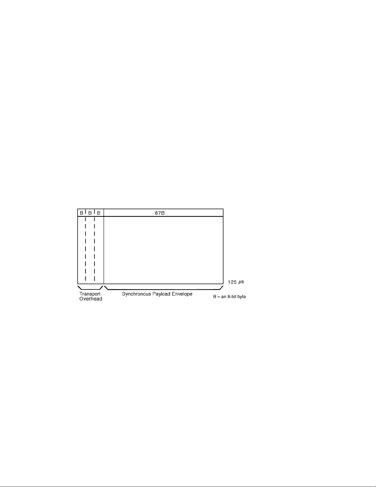
The frame format of the STS–1 signal is shown in Figure 1. In general, the frame
can be divided into two main areas: transport overhead and the synchronous
payload envelope (SPE).
Figure 1. STS–1 Frame Format
The synchronous payload envelope can also be divided into two parts: the STS
path overhead (POH) and the payload. The payload is the revenue-producing
traffic being transp orted and routed over the SONET n etwork. Once the payload
is multiplexed into the synchronous payload envelope, it can be transported and
switched through SONET without having to b e examined and possibly
demultiplexed at intermediate nodes. Thus, SONET is said to be serviceindependent or transparent.
Transport overhead is composed of section overhead and line overhead. The
STS–1 POH is part of the synchronous payload envelope.
The STS–1 payloa d has the capacity to transport up to the following:
• 28 DS–1s
Web ProForum Tutoria ls
http://www.iec.org
The International Engineering Consortium
Copyright ©
6/58
Page 7

• 1 DS–3
• 21 2.048 Mbps signals
• combinations of each
STS–1 Frame Structure
STS–1 is a specific sequence of 810 bytes (6,480 bits), which includes various
overhead bytes and an envelope capacity for transporting payloads. It can be
depicted as a 90-column by 9-row structure. Wi th a frame length of 125 µs
(8,000 frames per second), STS–1 has a bit rate of 51.840 Mbps. The order of
transmission of bytes is row- by-row from top to bottom and from left to right
(most significant bi t first).
As shown in Figure 1, the first three columns of the STS–1 frame are for the
transport overhead. The three columns contain 9 bytes. Of these, 9 bytes are
overhead for the section layer (for example, each section overhead), and 18 bytes
are overhead for the line layer (for example, line overhead). The remaining 87
columns constitute the STS–1 envelope capacity (pay load and POH).
As stated before, the basic signal of SONET is the STS–1. The STS frame format is
composed of 9 rows of 90 columns of 8-bit bytes, or 810 bytes. The byte
transmission order is row-by-row, left to right. At a rate of 8,000 frames per
second, that works out to a rate of 51.840 Mbps, as the following equation
demonstrates:
(9) x (90 bytes/frame) x (8 bits/byte) x (8,000 frames/s) =
51,840,000 bps = 51.840 Mbps
This is known as the STS–1 signal rate—the electri cal rate used primari ly for
transport within a specific piece of hardware. The optical equivalent of STS–1 is
known as OC–1, and it is used for transmission across the fiber.
The STS–1 frame consists of overhead, plus an SPE (see Figure 2). The first three
columns of each STS–1 frame make up the tran sport overhead, and the last 87
columns make up the SPE. SPEs can have any alignment within the frame, and
this alignme nt is indicated by the H1 and H2 pointer bytes in the line overh ead.
Web ProForum Tutoria ls
http://www.iec.org
The International Engineering Consortium
Copyright ©
7/58
Page 8
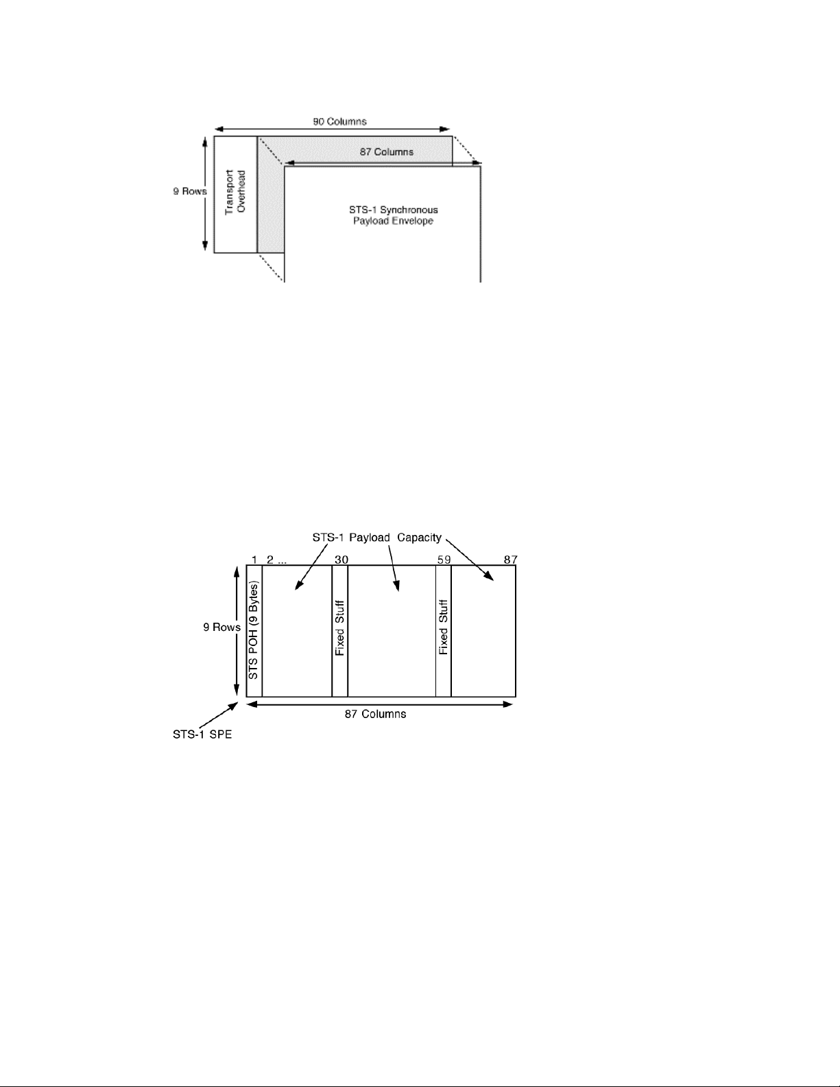
Figure 2. STS–1 Frame Elements
STS–1 Envelope Capacity and Synchronous
Payload Envel ope (SPE)
Figure 3 depicts the STS–1 SPE, which occupies the STS–1 envelope capacity.
The STS–1 SPE consists of 783 bytes, and can be depicted as an 87-column by 9row structure. Column 1 contains 9 bytes, designated as the STS POH. Two
columns (columns 30 and 59) are not used for payload but are designated as the
fixed-stuff columns. The 756 bytes in the remaining 84 columns are designated as
the STS–1 payload capacity.
Figure 3. STS–1 SPE Example
STS–1 SPE in Interior of STS–1 Frames
The STS–1 SPE may begin anywhere in the STS–1 envelope capacity (see Figure
4). Typically, it begins in one STS–1 frame and ends in the next. The STS payload
pointer contain ed in the transport overhead designates the loc ation of the byte
where the STS–1 SPE begins.
STS POH is associated with each payload and is used to communicate various
information from the point where a payload is mapped into the STS–1 SPE to
where it is delivered.
Web ProForum Tutoria ls
http://www.iec.org
The International Engineering Consortium
Copyright ©
8/58
Page 9
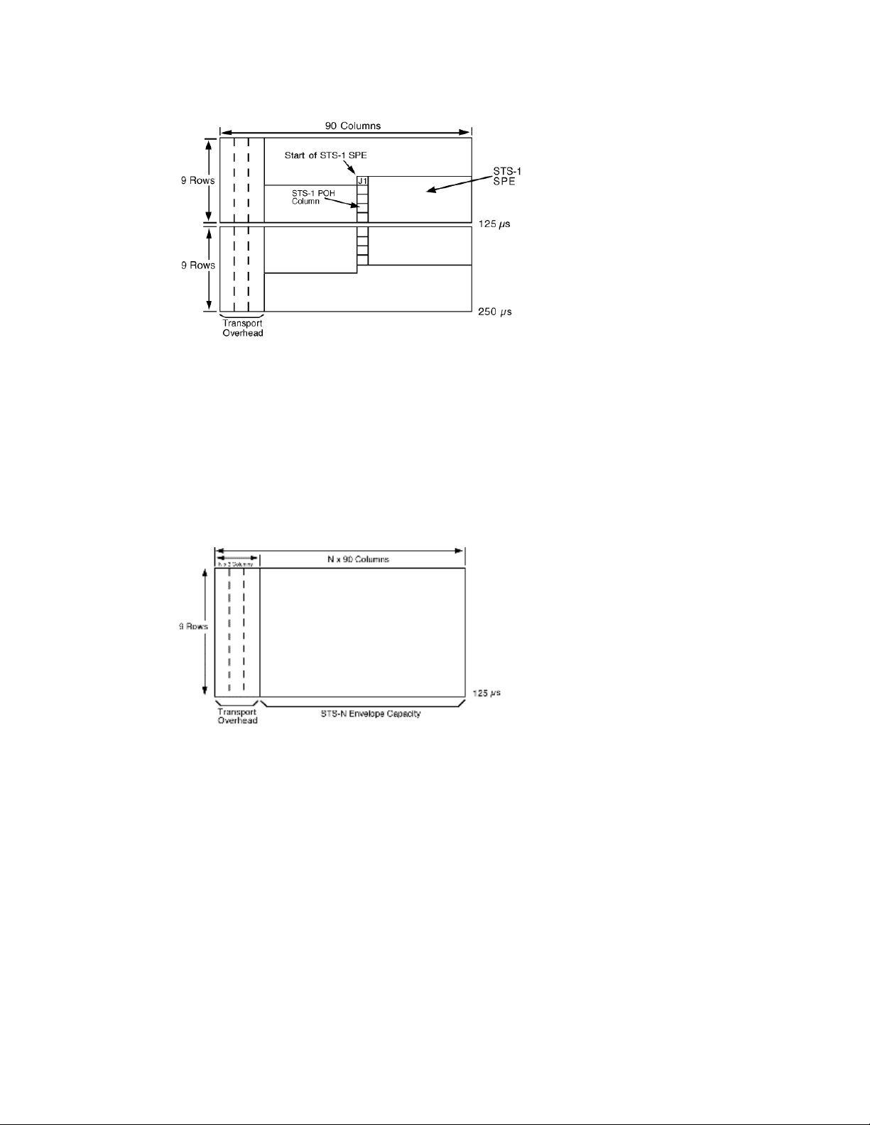
Figure 4. STS–1 SPE Position in the STS–1 Frame
STS–N Frame Structure
An STS–N is a specific sequence of Nx810 bytes. The STS–N is formed by byteinterleaving STS–1 modules (see Figure 5). The transport overhead of the
individual STS–1 modules are frame aligned before interleaving, but the
associated STS SPEs are not required to be aligned because each STS–1 has a
payload pointer to indicate the location of the SPE (or to indicate concatenation).
Figure 5. STS–N
`
4. Overheads
SONET provides substantial overhead information, allowing simpler
multiplexing and greatly expanded operations, administration, maintenance, and
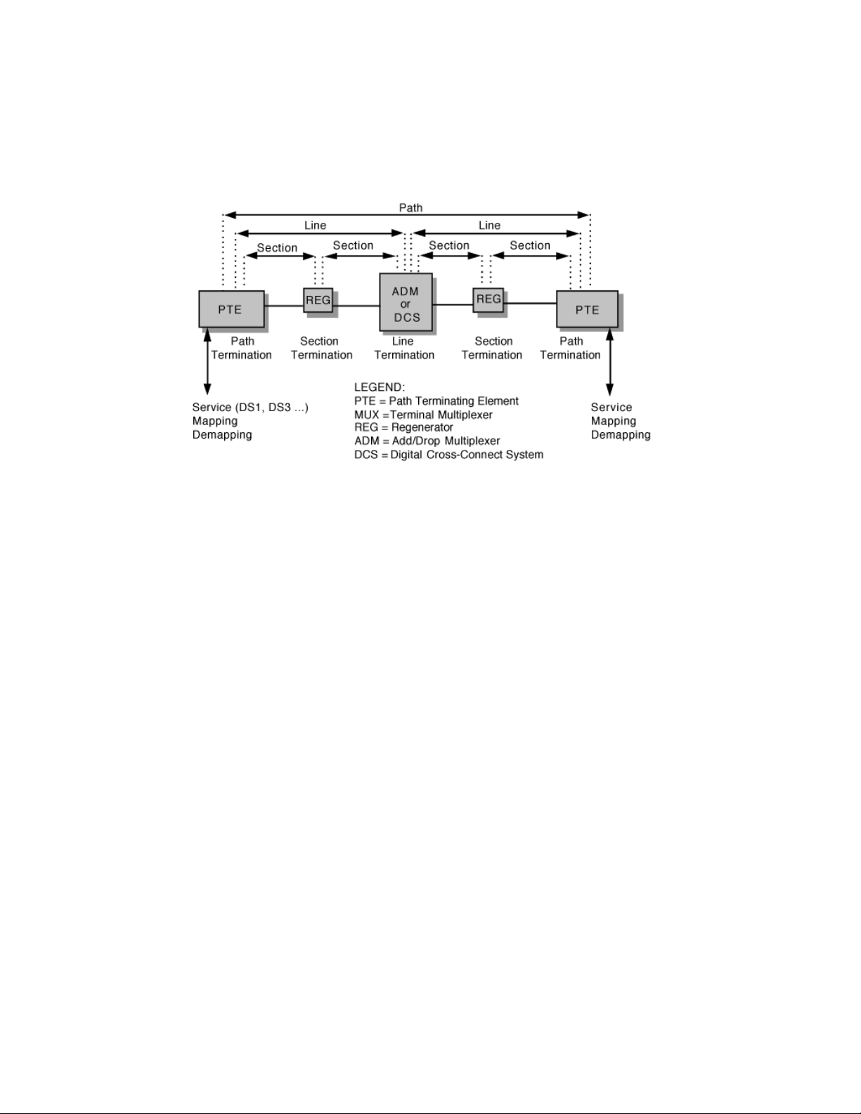
provisioning (OAM&P) capabilities. The overhead information has several layers,
which are shown in Figure 6. Path-level overhead is carried from end-to-end; it is
added to DS–1 signals when they are mapped into VTs and for STS–1 payloads
that travel end-to-end. Line overhead is for the STS–N signal between ST S–N
multiplexers. Section overhead is used for communications between adjacent
network elements such as regenerators.
Web ProForum Tutoria ls
http://www.iec.org
The International Engineering Consortium
Copyright ©
9/58
Page 10
Enough information is contained in the overhead to allow the network to operate
and allow OAM&P communications between an intelligent network controller
and the individual nodes.
Figure 6. Overhead Layers
The following sections detail the different SONET overhead information:
• section overhead
• line overhead
• STS POH
• VT POH
This information has been updated to refle ct changes in Bellcore GR–253, Issue
2, December 1995.
Section Overhead
Section overhead contains 9 bytes of the transport overhead accessed, generated,
and processed by section-terminating equipment. This overhead supports
functions such as the following:
• performance monitoring (STS–N signal)
• local orderwire
• data communication channels to carry information for OAM&P
Web ProForum Tutoria ls
http://www.iec.org
The International Engineering Consortium
Copyright ©
10/58
Page 11

• framing
This might be two regenerators, line-terminating equipment and a regenerator,
or two sets of line-terminating equipment. The section overhead is found in the
first three rows of columns 1 to 9 (See Figure 7).
Figure 7. Section Overhead–Rows 1 to 3 of Transport Overhead
Table 3 shows section overhead byte by byte.
Table 3. Section Overhead
Byte Description
A1
and
framing bytes—These two bytes indicate the beginning of an STS–1
frame.
A2
J0 section trace (J0 )/ s ection growth (Z0)—The byte in each of the N
STS–1s in an STS–N that was formally defined as the STS–1 ID (C1) byte
has been refined either as the section trace byte (in the fi rst STS–1 of the
STS–N), or as a section growth byte (in the second through Nth STS–1s).
B1 section bit-interleaved parity code (BIP–8) byte—This is a parity
code (even parity), used to check for transmission errors over a
regenerator section. Its value is calculated over all bits of the previous
STS–N frame after scrambling then placed in the B1 byte of STS–1 before
scrambling. Therefore, this byte is defined only for STS–1 number 1 of an
STS–N signal.
E1 section orderwire byte—This byte is allocated to be used as a local
orderwire channel for voice communication between regenerators, hubs,
and remote terminal locations.
Web ProForum Tutoria ls
http://www.iec.org
The International Engineering Consortium
Copyright ©
11/58
Page 12

F1 section user channel byte—This byte is set aside for the users'
purposes. It terminates at all section-terminating equipment within a line.
It can be read and written to at each section-terminating equipment in
that line.
D1,
D2,
and
D3
section data communications channel (DCC) bytes—Together,
these 3 bytes form a 192–kbps message channel providing a messagebased channel for OAM&P between pieces of section-terminating
equipment. The channel is used from a cen tral location for alarms,
control, monitoring, administration, and other communication needs. It is
available for internally generated, externally generated, or manufacturerspecific messages.
Line Overhead
Line overhead contains 18 bytes of overhead accessed, generated, and processed
by line-terminating equipment. This overhead supports functions such as th e
following:
• locating the SP E in the frame
• multiplexing or concatenating signals
• performance monitoring
• automatic protection switching
• line maintenance
Line overhead is found in rows 4 to 9 of columns 1 to 9 (see Figure 8).
Figure 8. Line Overhead: Rows 4 to 9 of Transport Overhead
Web ProForum Tutoria ls
http://www.iec.org
The International Engineering Consortium
Copyright ©
12/58
Page 13

Table 4 shows line overhead byte by byte.
Table 4. Line Overhead
Byte Description
H1
and
H2
STS payload pointer (H1 and H2)—Two bytes are allocated to a
pointer that ind icates the offset in bytes between the pointer and the first
byte of the STS SPE. The pointer bytes are used in all STS–1s within an
STS–N to align the STS–1 transport overhead in the STS–N and to
perform frequency justification. These bytes are also used to indicate
concatenation and to detect STS path alarm indication signals (AIS–P).
H3 pointer action byte (H3)—The pointer action byte is allocated for SPE
frequency justification purposes. The H3 byte is used in all STS–1s within
an STS–N to carry the extra SPE byte in the event of a negative pointer
adjustment. The value contained in thi s byte when it is not used to carry
the SPE byte is undefined.
B2 line bit-interleaved parity code (BIP–8) byte—Thi s parity code
byte is used to determine if a transmission error has occurred over a line.
It is even parity and is calculated over all bits of the line overhead and
STS–1 SPE of the previous STS–1 frame before scrambling. The value is
placed in the B2 byte of the line overhead before scrambling. This byte is
provided in all STS–1 signals in an STS–N signal.
K1
and
K2
automatic protection switching (APS channel) bytes—These 2
bytes are used for p rotection signaling between line-terminating entities
for bidirectional autom atic protection switching and for detecting alarm
indication signal (AIS–L) and remote defect indication (RDI) signals.
D4
to
D12
line data communications channel (DCC) bytes—These 9 bytes
form a 576–kbps message c ha nnel from a central location for OAM& P
information (alarms, control, maintenance, remote provisioning,
monitoring, administration, and other communication needs) between
line entities. They are available for internally generated, externally
generated, and manufacturer-specific messages. A protoc ol analyzer is
required to access the line–DCC informatio n.
S1 synchronization status (S1)—The S1 byte is located in the first STS–1
of an STS–N, and bits 5 through 8 of that byte are allocated to convey the
synchronization status of the network element.
Z1 growth (Z1)—The Z1 byte is located in the second through Nth S T S–1s
of an STS–N (3 <= N <= 48) and are allocated for future growth. Note
that an OC–1 or STS–1 electrical signal does not contain a Z1 byte.
Web ProForum Tutoria ls
http://www.iec.org
The International Engineering Consortium
Copyright ©
13/58
Page 14

M0 STS–1 REI–L (M0)—The M0 byte is only defined for STS–1 in an OC–1
or STS–1 electrical signal. Bits 5 through 8 are allocated for a line remote
error indication function (REI–L, formerly referred to as line FEBE),
which conveys the error count detected by an LTE (using the line BIP–8
code) back to its peer LTE.
M1 STS–N REI–L (M1)—The M1 byte is located in the third STS–1 (in
order of appearance in the byte-interleaved STS–N electrical or OC–N
signal) in an STS–N (N >= 3) and is used for a REI–L function.
Z2 growth (Z2)—The Z2 byte is located in the first and second STS–1s of
an STS–3 and the first, second, and fourth through Nth STS–1s of an
STS–N (12 <= N <= 48). These bytes are allocated for future growth.
Note that an OC–1 or STS–1 electrical signal does not contain a Z2 byte.
E2 orderwire byte—This orderwire byte provides a 64–kbps channel
between line entities for an express orderwire. It is a voice channel for use
by technicians and will be ignored as it passes through the regenerators.
STS POH
STS POH contains 9 evenly distributed POH bytes per 125 microseconds starting
at the first byte of the STS SPE. STS POH provides for communication between
the point of creation of an STS SPE and its point of disassembly. This overhead
supports functions such as the following:
• performance monitoring of the STS SPE
• signal label (the content of the STS SPE, including status of mapped
payloads)
• path status
• path trace
The POH is found in rows 1 to 9 of the first column of the STS– 1 SPE (see Figure
9).
Web ProForum Tutoria ls
http://www.iec.org
The International Engineering Consortium
Copyright ©
14/58
Page 15

V
Figure 9. POH in Rows 1 to 9
Table 5 describes POH byte by byte.
Table 5. STS POH
Byte Description
J1 STS path trace byte—This user-programmable byte repe titively
transmits a 64-byte, or 16-byte E.164 format string. This allows the
receiving terminal in a path to verify its continued connection to the
intended transmitting terminal.
B3 STS path bit-interleaved parity code (path BIP–8) byte—This is a
parity code (even) used to determine if a transmission error has occurred
over a path. Its value is calculated over all the bits of the previous SPE
before scrambling.
C2 STS path signal label byte—This byte is used to indicate the content of
the STS SPE, including the status of the mapped payloads.
G1 path status byte—This byte is used to convey the path-terminati ng
status and performance back to the originating path-ter minating
equipment. Therefore, the duplex path in its entirety can be monitored
from either end or from any point along the path. Bits 1 through 4 are
allocated for an STS path REI function (REI–P, formerly referred to as
STS path FEBE). Bits 5, 6, and 7 of the G1 byte are allocated for an STS
path RDI (RDI–P) signal. Bit 8 of the G1 byte is currently undefined.
F2 path user channel byte—This byte i s used for user communication
between path elements.
H4
Web ProForum Tutoria ls
http://www.iec.org
T multiframe indicator byte—This byte provides a generalized
Copyright ©
The International Engineering Consortium
15/58
Page 16
multiframe indicator for p ayload containers. At present, it is used only for
tributary unit structured payloads.
Note:
The POH portion of the SPE remains with the payload until it is demultiplexed.
VT POH
VT POH contains four evenly distributed POH bytes per VT SPE starting a t the
first byte of the VT SPE. VT POH provides for communi cation between the poin t
of creation of an VT SPE and its point of disassembly.
Four bytes (V5, J2, Z6, and Z7) are allocated for VT POH. The first byte of a VT
SPE (i.e., the byte in the location pointed to by the VT payload pointer) is the V5
byte, while the J2, Z6, and Z7 bytes occupy the corresponding locations in the
subsequent 125-microsecond frames of the VT superframe.
The V5 byte provides the same functions for VT paths that the B3, C2, and G1
bytes provide for STS paths—namely error checking, signal label, and path status.
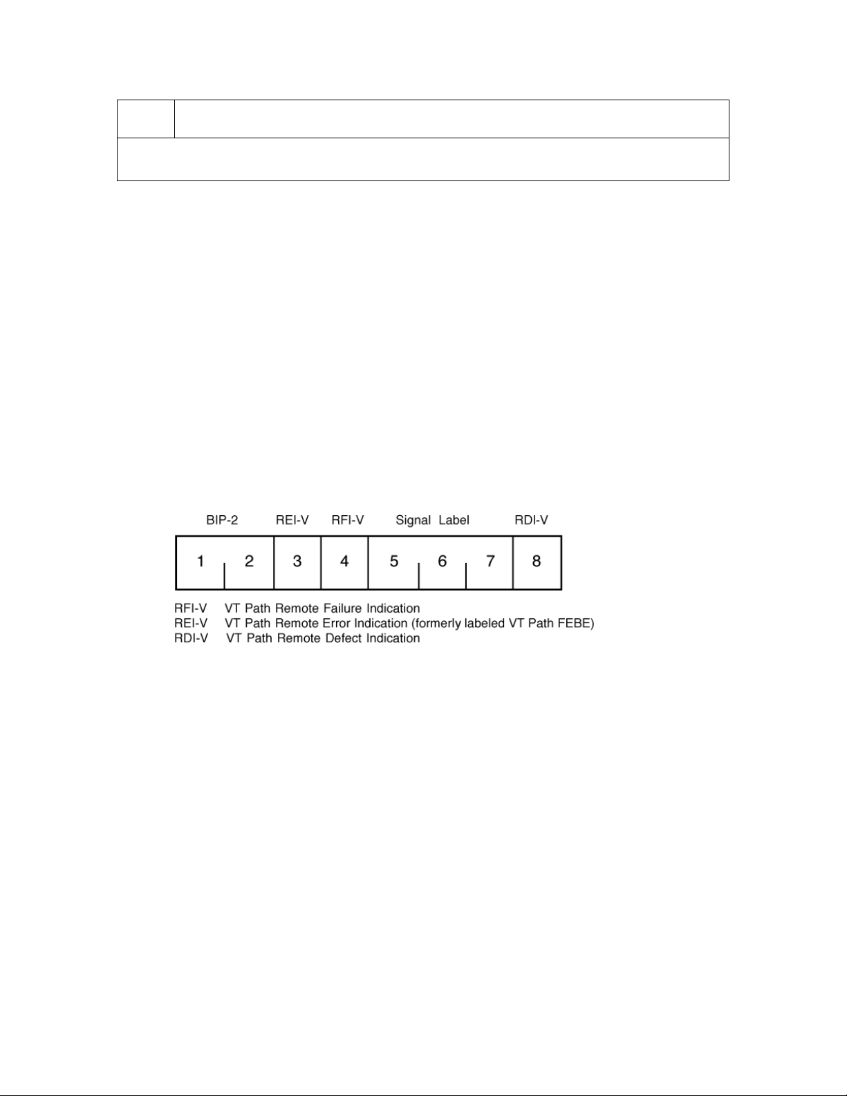
The bit assignments for the V5 byte are illustrated in Figure 10.
Figure 10. VT POH—V5 Byte
Bits 1 and 2 of the V5 byte are allocated for error performance monitoring. Bit 3
of the V5 byte is allocated for a VT path REI function (REI–V, formerly referred
to as VT path FEBE) to c onvey the VT path terminating performance back to an
originating VT PTE. Bit 4 of th e V5 byte is allocated for a VT path remote failure
indication (RFI–V) in the byte-synchronous DS–1 mapping. Bits 5 through 7 of
the V5 byte are allocated for a VT path signal label to indicate the content of the
VT SPE. Bit 8 of the VT byte is allocated for a VT path remote defect indication
(RDI–V) signal.
SONET Alarm Structure
The SONET frame structure has been designed to contain a large amount of
overhead information. The overhead information provides a variety of
management and other functions such as the following:
Web ProForum Tutoria ls
http://www.iec.org
The International Engineering Consortium
Copyright ©
16/58
Page 17

• error performance monitoring
• pointer adjustment information
• path status
• path trace
• section trace
• remote defect, error, and failure indications
• signal labels
• new data flag ind ications
• data communications channels (DCC)
• automatic protection switching (APS) control
• orderwire
• synchronization status message
Much of this overhead information is involved with alarm and in-service
monitoring of the particular SONET sections.
SONET alarms are defined as follows:
• anomaly—This is the smallest discrepancy that can be observed
between the actua l and desired characteristics of an item. The
occurrence of a single anomaly does not constitute an interruption in
the ability to perform a required function.
• defect—The density of anomalies has reached a level where the ability
to perform a required function has been interrupted. Defects are used
as input for performanc e monitoring, the control of consequent
actions, and the determination of fault cause.
• failure—This is the inability of a function to perform a required action
persisted beyond the maximum time allocated.
Table 6 describes SONET alarm anomalies, defects, and failures.
Web ProForum Tutoria ls
http://www.iec.org
The International Engineering Consortium
Copyright ©
17/58
Page 18

Table 6. Anomalies, Defects, and Failures
Description Criteria
loss of signal
(LOS)
out of frame
(OOF)
alignment
loss of frame
(LOF) alignment
loss of pointer
(LOP)
LOS is raised when the synchronous signal (STS–N)
level drops below the threshold at which a BER of 1 in
103 is predicted. It could be due to a cut cable,
excessive atten uation of the signal, or equipment
fault. LOS state clears when two consecutive framing
patterns are received and no new LOS condition is
detected.
OOF state occurs when four or five consecutive
SONET frames are received with invalid (errored)
framing patterns (A1 and A2 bytes). The maximum
time to detect OOF is 625 microseconds. OOF state
clears when two consecutive SONET frames are
received with valid framing patterns.
LOF state occurs when the OOF state exists for a
specified time in milliseconds. LOF state clears when
an in-frame condition exists continuously for a
specified time in milliseconds.
LOP state occurs when N consecutive invalid pointers
are received or N consecutive new data flags (NDFs)
are received (other than in a concatenation indicator),
where N = 8, 9, or 10. LOP state clears when three
equal valid poi nters or three consecutive AIS
indications are received.
alarm indication
signal (AIS)
Web ProForum Tutoria ls
http://www.iec.org
LOP can also be ide ntified as follows:
• STS path loss of pointer (SP–LOP)
• VT path loss of pointer (VP–LOP)
The AIS is an all-ones characteristic or adapted
information signal. It is generated to replace the
normal traffic signal when it contains a defect
condition in order to prevent consequential
downstream failures being declared or alarms being
raised.
AIS can also be identified as follows:
Copyright ©
The International Engineering Consortium
18/58
Page 19

• line alarm indication signal (AIS–L)
• STS path alarm indication signal (SP–AIS)
• VT path alarm indication signal (VP–AIS)
remote error
indication (REI)
remote defect
indication (RDI)
This is an indication returned to a transmitting node
(source) that an errored block has been detected at
the receiving node (sink). This indication was
formerly known as far end block error (FEBE).
REI can also be identified as the following:
• line remote error indication (REI–L)
• STS path remote error indication (REI–P)
• VT path remote error indication (REI–V)
This is a signal returned to the transmitti ng
terminating equipment upon detecting a loss of
signal, loss of frame, or AIS defect. RDI was
previously known as FERF.
RDI can also be identified as the following:
• line remote defe ct indication (RDI–L)
remote failure
indication (RFI)
Web ProForum Tutoria ls
http://www.iec.org
• STS path remote defect indication (RDI–P)
• VT path remote defect indication (RDI–V)
A failure is a defect that persists beyond the
maximum time allocated to the trans mission system
protection mechanisms. When this situation occurs,
an RFI is sent to the far end and will initiate a
protection switch if this function has been enabled.
RFI can also be ide ntified as the following:
• line remote failure indication (RFI–L)
• STS path remote failure indication (RFI–P)
• VT path remote failure indication (RFI–V)
Copyright ©
The International Engineering Consortium
19/58
Page 20

B1 error Parity errors evaluated by byte B1 (BIP–8) of an STS–
N are monitored. If any of the eight parity checks fail,
the corresponding block is assumed to be in error.
B2 error Parity errors evaluated by byte B2 (BIP–24 x N) of an
STS–N are monitored. If any of the N x 24 pa rity
checks fail, the corresponding block is assumed to be
in error.
B3 error Parity errors evaluated by byte B3 (BIP–8) of a VT–N
(N = 3, 4) are monitored. If any of the eight parity
checks fail, the corresponding block is assumed to be
in error.
BIP–2 error Parity errors contained in bits 1 and 2 (BIP–2: bit
interleaved parity–2) of byte V5 of an VT–M (M = 11,
12, 2) are monitored. If any of the two parity checks
fail, the corresponding block is assumed to be in
error.
loss of sequence
synchronization
(LSS)
Bit error measurements using pseudo-random
sequences can only be performed if the reference
sequence produced on the synchronization receiving
side of the test set-up is correctly synchronized to the
sequence coming from the object under test. To
achieve compatible measurement results, it is
necessary to specify that the sequence
synchronization characteristics.
Sequence synchronization is considered to be lost and
resynchronization shall be started if the following
occur:
• Bit error ratio is greater than or equal to
0.20 during an integration interval of 1
second.
• It can be unambiguously identified that the
test sequence and the reference sequence
are out of phase.
Note:
One method to recognize the out-of-phase condition is the evaluation of the error pattern resulting from the
bit-by-bit comparison. If the error pattern has the same structure as the pseudo-random test sequence, the
out-of-phase co ndition is reached.
Web ProForum Tutoria ls
http://www.iec.org
The International Engineering Consortium
Copyright ©
20/58
Page 21

5. Pointers
SONET uses a con cept called pointers to compensate for frequency and phase
variations. Pointers allow the transparent transport of synchronous payload
envelopes (either STS or VT) across plesiochronous boundaries (i.e., between
nodes with separate network clocks having almost the same timin g). The use of
pointers avoids the delays and loss of data associated with the use of large (125microsecond frame) slip buffers for synchronization.
Pointers provide a simple means of dynamically and flexibly phase-aligning STS
and VT payloads, thereby permitting ease of dropping, inserting, and crossconnecting thes e payloads in the n etwork. Transmission signal wander and jitte r
can also be readily minimized with pointers.
Figure 11 shows an STS–1 pointer (H1 a nd H2 bytes), which allows the SPE to be
separated from the transport overhead. The poi nter is simply an offset value that
points to the byte where the SPE begins. Figure 11 depicts the typical case of the
SPE overlapping onto two STS–1 frames. If there are any frequency or phase
variations between the STS–1 frame and its SPE, the pointer value will be
increased or decreased accordingly to maintain synchronization.
Figure 11. Pointer—SPE Position in the STS–1 Frame
VT Mappings
There are several options for how payloads are actually mapped into the VT.
Locked-mode VTs bypass the pointers with a fixed byte-oriented mapping of
limited flexibility. Floating mode mappings use the pointers to allow the payloa d
to float within the VT payload. There are three different floating mode
mappings—asynchronous, bit-synchronous, and byte-synchronous.
Concatenated Payloads
For future services, th e STS–1 may not have enough capacity to carry some
services. SONET offers the flexibility of concatenating STS–1s to provide the
Web ProForum Tutoria ls
http://www.iec.org
The International Engineering Consortium
Copyright ©
21/58
Page 22

necessary bandwidth (consult the Glossary for an explanation of concatenation).
STS–1s can be concatenated up to STS–3c. Beyond STS–3, concatenation is done
in multiples of STS–3c. VTs can be concatenated up to VT–6 in increments of
VT–1.5, VT–2, or VT–6.
Payload Pointers
When there is a difference in phase or frequency, the pointer value is adjusted. To
accomplish thi s, a process known as byte stuffing is used. In other words, the SPE
payload pointer indicates where in the container capacity a VT starts, and the
byte-stuffing process allows dynamic alignment of the SPE in case it slips in time.
Positive Stuffing
When the frame rate of the S PE is too slow in relation to the rate of the STS–1,
bits 7, 9, 11 , 13, and 15 of the pointer word are inverted in one frame, thus
allowing 5-bit majority voting at the receiver. These bits are known as the I-bits
or increment bits. Periodically, when the SPE is about one byte off, these bits are
inverted, indicating that positive s tuffing must occur. An additional byte is
stuffed in, allowi ng the alignment of the container to slip back in time. This is
known as positive stuffing, and the stuff byte is made up of noninform ation bits.
The actual positive stuff byte immediately follows the H3 byte (that is, the stuff
byte is within the SPE portion). The pointer is incremented by one in the next
frame, and the subsequent pointers contain the new value. Simply put, if the SPE
frame is traveling more slowly than the STS–1 frame, every now and then s tuffing
an extra byte in the flow gives the SPE a one -byte delay (see Figure 12).
Figure 12. Payload Pointer—Positive Justification
Web ProForum Tutoria ls
http://www.iec.org
Copyright ©
The International Engineering Consortium
22/58
Page 23

Negative Stuffing
Conversely, when the frame rate of the SPE frame is too fast in relation to the rate
of the STS–1 frame, bits 8, 10, 12, 14, and 16 of the pointer word are inverted,
thus allowing 5-bit majority voting at the receiver. These bits are known as the Dbits or decrement bits. Periodically, when the SPE frame is about one byte off,
these bits are inverted, indicating that negative stuffing must occur. Because the
alignment of the container advances in time, the envelope capacity must be
moved forward. Thus , actual data is written in the H3 byte, th e negative stuff
opportunity (within the overhead); th is is known as negative stuffing.
The pointer is decremented by one in the next frame, and the subsequent
pointers contain the new value. Simply put, if the SPE frame is traveling more
quickly than the S TS–1 frame, every now and then pulling an ex tra byte from the
flow and stuffing it into the overhead capacity (the H3 byte) gives the SPE a onebyte advance. In either case, there must be at least three frames in which the
pointer remains constant before another stuffing operation (and therefore a
pointer value change) can occur (see Figure 13).
VTs
Figure 13. Payload Pointer—Negative Justification
In addition to the STS–1 base format, SONET also defines synchronous formats
at sub–STS–1 levels. The STS–1 payload may be subdivided into VTs, which are
synchronous signals used to transport lower-speed transmissions. The sizes of
VTs are displayed in Table 7.
Web ProForum Tutoria ls
http://www.iec.org
The International Engineering Consortium
Copyright ©
23/58
Page 24

Table 7. VTs
VT Type Bit Rate (Mbps) Size of VT
VT 1.5 1.728 9 rows, 3 columns
VT 2 2.304 9 rows, 4 columns
VT 3 3.456 9 rows, 6 columns
VT 6 6.912 9 rows, 12 columns
To accommodate mixes of different VT types within an STS–1 SPE, the VTs are
grouped together. An STS–1 SPE that is carrying VTs is divided into seven VT
groups, with each VT group usi ng 12 columns of the STS–1 SPE; note that the
number of columns in each of the different VT types (3, 4, 6, and 12) are all
factors of 12. Each VT group can contain only one size (type) of VT, but within an
STS–1 SPE, there can be a mix of the different VT groups.
For example, an STS–1 SPE may contain four VT1.5 groups and three VT6
groups, for a total of seven VT groups. Thus, an SPE can carry a mix of any of the
seven groups. The groups have no overhead or pointers; they are just a means of
organizing the different VTs within an STS–1 SPE.
Because each of th e VT groups is allocated 12 columns of the SPE, a VT group
would contain one of the following combinations:
• four VT1.5s (with 3 columns per VT1.5)
• three VT2s (with 4 columns per VT2)
• two VT3s (with 6 columns per VT3)
• one VT6 (with 12 columns per VT6)
The 12 columns in a VT group are not consecutive within the SPE; they are
interleaved column by column with respect to the other VT groups. In addition,
column 1 is used for th e POH; the two columns of fi xed stuff are assigned to
columns 30 and 59.
The first VT group, called group 1, is found in every seventh column, starting with
column 2 and skipping columns 30 and 59. That is, the 12 columns for VT group 1
are columns 2, 9, 16, 23, 31 , 38, 45, 52, 60, 67, 74, and 81.
Just as the VT group columns are not placed in consecutive columns in an STS–1
SPE, the VT column s within a group are not placed in consecutive columns
Web ProForum Tutoria ls
http://www.iec.org
The International Engineering Consortium
Copyright ©
24/58
Page 25

within that group. The columns of the individual VTs within the VT group are
interleaved as well (see Figure 14).
Figure 14. SONET Tributaries—VT Structured STS–1 SPE
The VT structure is designed for transport and switching of sub–STS–1 rate
payloads. There are four sizes of VTs: VT1.5 (1.728 Mbps), VT2 (2.30 4 Mbps),
VT3 (3.456 Mbps), and VT6 (6.912 Mbps). In the 87-column by 9-row s tructure
of the STS–1 SPE, these VTs occupy columns 3, 4, 6, and 12, respectively.
To accommodate a mi x of VT sizes efficiently, the VT–structured STS–1 SPE is
divided into seven VT groups. Each VT group occupies 12 columns of the 87
column STS–1 SPE and may contain 4 VT1.5s, 3 VT2s, 2 VT3s, or 1 VT6. A VT
group can contain only one size of VTs; however, a different VT size is allowed for
each VT group in an STS–1 SPE (see Figure 15).
Figure 15. VT Structure, VT Sizes
Web ProForum Tutoria ls
http://www.iec.org
The International Engineering Consortium
Copyright ©
25/58
Page 26

STS–1 VT1.5 SP E Columns
One of the benefits of SONET is that it can carry large payloads (above 50 Mbps).
However, the existing digital hierarchy can be accommodated as well, thus
protecting investments in current equipment. To achieve this capacity, the STS
SPE can be subdivided into smaller components or structures, known as VTs for
the purpose of transporting and switching payloads smaller than the STS–1 rate.
All services below the DS–3 rate are transported in the VT structure. Figure 16
shows the VT1.5–structured STS–1 SPE. Table 8 matches up the VT1.5 locations
and the STS–1 SPE column numbers, per the Bellcore GR–253–CORE standard.
Figure 16. STS–1 VT1.5 SPE Columns
Table 8. VT1.5 Locations matched to the STS–1 SPE Column
Numbers
VT
Number
1
VT Group
Number
Column
Numbers
1 2, 31, 60
2 3, 32, 61
3 4, 33, 62
4 5, 34, 63
5 6, 35, 64
6 7, 36, 65
7 8, 37, 66
2 1 9, 38, 67
Web ProForum Tutoria ls
http://www.iec.org
The International Engineering Consortium
Copyright ©
26/58
Page 27

3
2 10, 39, 68
3 11, 40, 69
4 12, 41, 70
5 13, 42, 71
6 14, 43, 72
7 15, 44, 73
1 16, 45, 74
2 17, 46, 75
3 18, 47, 76
4 19, 48, 77
5 20, 49, 78
6 21, 50, 79
7 22, 51, 80
4
1 23, 52, 81
2 24, 53, 82
3 25, 54, 83
4 26, 55, 84
5 27, 56, 85
6 28, 57, 86
7 29, 58, 87
Notes:
column 1 = STS–1 POH
30 = fixed stuff
59 = fixed stuff
Web ProForum Tutoria ls
http://www.iec.org
The International Engineering Consortium
Copyright ©
27/58
Page 28

DS–1 Visibility
Because the multiplexing is synchronous, the low-speed tributaries (input
signals) can be multiplexed together but are still visible at higher rates. An
individual VT containing a DS–1 can be extracted without demultiplexing the
entire STS–1. This improved accessibility improves switching and grooming at
VT or STS levels.
In an asynchronous DS–3 frame, the DS–1s have gone through two levels of
multiplexing (DS–1 to DS –2; DS–2 to DS–3) which i nc lude the addition of
stuffing and framing bits. The DS–1 signals are mixed somewhere in the
information-bit fields and cannot be easily identified without completely
demultiplexing the entire frame.
Different synchronizing techniques are used for multiplexing. In existing
asynchronous systems, the timing for each fiber-optic transmission system
terminal is not locked onto a common clock. Therefore, large frequency
variations can occur. Bit stuffing is a technique used to synchronize the various
low-speed signals to a common rate before multiplexing.
VT Superframe and Envelope Capacity
In addition to the division of VTs into VT groups, a 500-microsecond structure
called a VT superframe is defined for each VT. The VT superframe contains the
V1 and V2 bytes (the VT payload pointer), and the VT envelope capacity, which in
turn contains the VT SPE. The VT envelope capacity, and therefore the size of the
VT SPE, is different for each VT size. V1 is the first by te in the VT superframe,
while V2 through V4 appear as the first bytes in the following frames of the VT
superframe, regardless of the VT size (see Figure 17).
Figure 17. VT Superframe and Envelope Capacity
Web ProForum Tutoria ls
http://www.iec.org
The International Engineering Consortium
Copyright ©
28/58
Page 29

VT SPE and Payload Capacity
Four consecutive 125-microsecond frames of the VT–structured STS–1 SPE are
organized into a 500-microsecond superframe, the phase of which is indicated by
the H4 (indicator) byte in the STS POH.
The VT payload pointer provides flexible and dynamic alignment of the VT SPE
within the VT envelope capacity, independent of other VT SPEs. Figure 18
illustrates the VT SPEs corresponding to the four VT sizes. Each VT SPE contains
4 bytes of VT POH (V5, J2, Z6, and Z7), and the remaining bytes constitute the
VT payload capacity, which is different for each VT.
Figure 18. VT SPE and Payload Capacity
6. SONET Multiplexing
The multiplexing principle s of SONET are as follows:
• mapping—used when tributaries are adapte d into VTs by adding
justification bits and POH information
• aligning—takes place when a pointer is included in the STS path or VT
POH, to allow the first byte of the VT to be located
• multiplexing—used when multiple lower order path-layer signals are
adapted into a higher-order path signal, or when the higher-order path
signals are adapted into the line overhead
• stuffing—SONET has the ability to handle various input tributary
rates from asynchronous signals; as the tributary signals are
Web ProForum Tutoria ls
http://www.iec.org
The International Engineering Consortium
Copyright ©
29/58
Page 30

multiplexed and aligned, some spare capacity has been designed into
the SONET frame to provide enough space for all these various
tributary rates; therefore, at certain points in the multiplexing
hierarchy, this space capacity is filled with fixed stuffing bits that carry
no information but are required to fill up the pa rticular frame
One of the benefits of SONET is that it can carry large payloads (above 50 Mbps).
However, the existing digital hierarchy signals can be accommodated a s well,
thus protecting investments in current equipment.
To achieve this capability, the STS SPE ca n be sub-divided into smaller
components or structures, known as VTs, for the purpose of transporting and
switching payloads smaller than the STS–1 rate. All services below DS–3 rate are
transported in the VT structure.
Figure 19 illustrates the bas ic multiplexing structure of SONET. Any type of
service, ranging from voice to high-speed data and video, can be accepted by
various types of service adapters. A service adapter maps the signal into the
payload envelope of the STS–1 or VT. New services and signals can be
transported by adding new service adapters at the edge of the SONET network.
Figure 19. SONET Multiplexing Hierarchy
Except for concatenated signals, all inputs are even tually converted to a base
format of a synchronous STS–1 signal (51.84 Mbps or higher). Lower-speed
inputs such as DS–1s are first bit- or byte-multiplexed into VTs. Several
synchronous STS–1s are then multiplexed together in either a single- or twostage process to form an electrical STS–N signal (N >= 1).
STS multiplexing is performed at the byte interleave synchronous multiplexer.
Basically, the bytes are interleaved together in a format such that the low-speed
signals are visible. No additional signal processing occurs except a direct
conversion from elec trical to optical to form an OC–N signal.
Web ProForum Tutoria ls
http://www.iec.org
The International Engineering Consortium
Copyright ©
30/58
Page 31

7. SONET Network Elements
Terminal Multiplexer
The path terminatin g element (PTE), an entry- level path-terminating terminal
multiplexer, acts as a concentrator of DS–1s as well as other tributary signals. Its
simplest deployment would involve two terminal multiplexers linked by fiber
with or without a regenerator in the link. This implementation represents the
simplest SONET link (a section, line, and path all in one link; see Figure 20).
Figure 20. Terminal Multiplexer
Regenerator
A regenerator is needed when, due to the long distance between multiplexers, the
signal level in the fiber becomes too low.
The regenerator clocks itself off of the received signal and replac es the section
overhead bytes before retransmitting the signal. The line overhead, payload, and
POH are not altered (see Figure 21).
Figure 21. Regenerator
Add/Drop Multiplexer (ADM)
Although network elements (NEs) are compatible at the OC–N level, they may
differ in features from vendor to vendor. SONET does no t restrict manufacturers
to providing a single type of product, nor require them to provide all types. For
example, one vendor might offer an add/drop multiplexer with access at DS–1
only, whereas another might offer simultaneous access at DS–1 and DS–3 rates
(see Figure 22).
Web ProForum Tutoria ls
http://www.iec.org
The International Engineering Consortium
Copyright ©
31/58
Page 32

Figure 22. Add/Drop Multiplexer
A single-stage multiplex er/demultiplexer can multiplex various inputs into an
OC–N signal. At an add/drop site, only those signals that need to be accessed are
dropped or inserted. The remaining traffic continues through the network
element without requiring special pas s-through units or other signal processing.
In rural applications, an ADM can be deployed at a terminal site or any
intermediate location for consolidating traffic from widely separated locations.
Several ADMs can also be configured as a survivable ring.
SONET enables drop and repeat (also known as drop and continue)—a key
capability in both telephony and cable TV applications. With drop and repeat, a
signal terminates at one node, is duplicated (repeated), and is then sent to the
next and subsequent nodes.
In ring-survivability applications, drop and repeat provides alternate routing for
traffic passing through interconnecting rings in a matche d-nodes configuration.
If the connectio n cannot be made through one of the nodes, the signal is repeated
and passed along an alternate route to the destination node.
In multinode distribution applications, one transport channel can efficiently
carry traffic betwee n multiple distribution nodes. When transporting video, for
example, each programming channel is delivered (dropped) at the node and
repeated for delivery to the next and subsequent nodes. Not all bandwidth
(program channels) need be terminated at all the nodes. Channels not
terminating at a n ode can be passed through without physical interve ntion to
other nodes.
The add/drop multiplexer provides interfaces between the different network
signals and SONET signals.
Single-stage multiplexing can multiplex/demultiplex one or more tributary (DS–
1) signals into/from an STS–N signal. It can be used in terminal sites,
intermediate (add/drop) sites, or hub configurations. At an add/drop site, it can
drop lower-rate signals to be transported on different facilities, or it can add
lower-rate signals into the higher-rate STS–N signal. The rest of the traffic simply
continues straight through.
Web ProForum Tutoria ls
http://www.iec.org
The International Engineering Consortium
Copyright ©
32/58
Page 33

Wideband Digital Cross-Connects
A SONET cross-connect accepts various optical carrier rates, accesses the STS–1
signals, and switches at this level. It is ideally used at a SONET hub. One major
difference between a cross-connect and an add/drop multiplexer is that a crossconnect may be used to interconnect a much larger number of STS–1s. The
broadband cross-connect can be used for grooming (consolidating or
segregating) of STS–1s or for broadband traffic management. For example, it may
be used to segregate high -bandwidth from low-ban dwidth traffic and send it
separately to the high-bandwidth (e.g., vi deo) switch and a low-bandwidth (voice)
switch. It is the synchronous equivalent of a DS–3 digital cross-connect and
supports hubbed network architectures.
This type is similar to the broadband cross-connect except that the switching is
done at VT levels (similar to DS–1/DS–2 levels). It is similar to a DS–3/1 crossconnect because it accepts DS–1s, DS–3s and is equipped with optical interfaces
to accept optical carrier signals. It is suitable for DS–1 level grooming
applications at hub locations. One major advantage of wideband digital crossconnects is that les s demultiplexing and multiplexing is required because only the
required tributaries are accessed and switche d.
The wideband digital cross-connect (W–DCS) is a digital cross-connect that
terminates SONET and DS–3 signals, and has the basic functionality of VT and
DS–1–level cross-connections. It is the SONET equivalent to the DS–3/DS–1
digital cross-connect and accepts optical OC–N signals as well as STS–1s, DS–1s,
and DS–3s.
In a wideband digital cross-connect, the switching is done at the VT level (i.e ., it
cross-connects the constituent VTs between STS–N terminatio ns).
Because SONET is synchronous, the low-speed tributaries are visible and
accessible within the STS–1 signal. Therefore, the required tributaries can be
accessed and switched without demultiplexing, whic h is not possible with
existing digital cross-connects. In addition, the W–DCS cross-connects the
constituent DS–1s between DS–3 terminations, a nd between DS–3 and DS–1
terminations.
The features of the W–DCS make it useful in several applicatio ns. Because it can
automatically cross-connect VTs and DS–1s, the W–DCS can be used as a
network-management system. This capabi lity in turn makes the W–DCS ideal for
grooming at a hub location (see Figure 23).
Web ProForum Tutoria ls
http://www.iec.org
The International Engineering Consortium
Copyright ©
33/58
Page 34

Figure 23. Wideband Digital Cross-Connect
Broadband Digital Cross-Connect
The broadband digital cross-connect interfaces various SONET signals and DS–
3s. It accesses the STS–1 signals, and switches at this level. It is the synchronous
equivalent of the DS–3 digital cross-connect, except that the broadband digital
cross-connect accepts optical signals and allows overhead to be maintained for
integrated OAM&P (asynchronous systems prevent overhead from being passed
from optical signal to signal).
The broadband digital cross-connect can make two-way cross-connections at the
DS–3, STS–1, and STS–Nc levels. It is best used as a SONET hub, where it can be
used for grooming STS–1s, for broadband restoration purposes, or for routing
traffic (see Figure 24).
Figure 24. Broadband Digital Cross-Connect
Digital Loop Carrier
The digital loop carrier (DLC) may be considered a concentrator of low-speed
services before they are brought i nto the local central office (CO) for distribution.
If this concentration were not done, the number of subscribers (or lines) that a
CO could serve would be limited by the number of lines served by the CO . The
DLC itself is actually a system of multiplexers and switches designed to perform
concentration from the remote terminals to the community dial office and, from
there, to the CO.
Web ProForum Tutoria ls
http://www.iec.org
The International Engineering Consortium
Copyright ©
34/58
Page 35

Whereas a SONET multiplexer may be deployed at the customer premises, a DLC
is intended for service in the CO or a controlled environment vault (CEV) that
belongs to the carrier. Bellcore document TR–TSY–000303 describes a generic
integrated digital loop carrier (IDLC), which consists of intelligent remote digital
terminals (RDTs) an d digital switch elements called integrated digital terminals
(IDTs), which are connected by a digital line. The IDLCs are designed to more
efficiently integrate DLC systems with existing digital switches (see Figure 25).
Figure 25. Integrated Digital Loop Carrier
8. SONET Network Configurations
Point-to-Point
The SONET multiplexer, an entry level path-terminating terminal multiplexer,
acts as a concentrator of DS–1s as well as other tributaries. Its simplest
deployment involves two terminal multiplexers linked by fiber with or without a
regenerator in the link. This implementation repre sents the simplest SONET
configuration.
In this configuration (see Figure 26), the SONET path and the service path (DS–1
or DS–3 links end-to-end) are identical, and this synchronous island can exist
within an asynchronous network world. In the future, point-to-point service path
connections will span across the whole network and will always originate and
terminate in a multiplexer.
Figure 26. Point-to-Point
Point-to-Multipoint
A point-to-multipoint (linear add/drop) architecture includes adding and
dropping circuits along the way. The SONET ADM (add/drop multiplexer) is a
unique network elemen t specifically designed for this task. It avoids the current
Web ProForum Tutoria ls
http://www.iec.org
The International Engineering Consortium
Copyright ©
35/58
Page 36

cumbersome network architecture of demultiplexing, cross-connecting, adding
and dropping channels, and then remultiplexing. The ADM is typically placed
along a SONET link to facilitate adding and dropping tributary channels at
intermediate points in the network (se e Figure 27).
Figure 27. Point-to-Multipoint
Hub Network
The hub network archite cture accommodates unexpected growth and cha nge
more easily than simple point-to-poi nt networks. A hub (Figure 28) concentrates
traffic at a central site and allows easy re provisioning of the circuits.
Figure 28. Hub Network
The following are two possible implementations of this type of network:
1. using two or more ADMs, and a wideband cross-connect switch, which
allows cross-conne cting the tributary services at the tributary level
2. using a broadband digital cross-connect switch, which allows crossconnecting at both the SONET level and the tri butary level
Ring Architecture
The SONET building block for a ring architecture is the ADM. Multiple ADMs can
be put into a ring configuration for either bidirectional or unidirectional traffic
(see Figure 29). The main advantage of the ring topology is its survivability; if a
Web ProForum Tutoria ls
http://www.iec.org
The International Engineering Consortium
Copyright ©
36/58
Page 37

fiber cable is cut, the multiplexers have the intelligenc e to send the services
affected via an alternate path through the ring without interruption.
Figure 29. Ring Architecture
The demand for survivable services, diverse routi ng of fiber facilities, flexibility to
rearrange services to alternate serving nodes, as well as automatic restoration
within seconds, have made rings a popular SONET topology.
9. What Are the Benefits of SONET?
The transport network using SONET provides much more powerful networking
capabilities than existing asynchronous systems.
Pointers, MUX/DEMUX
As a result of SONET transmission, the network's clocks are referenced to a
highly stable reference point. Therefore, the need to align the data streams or
synchronize clocks is unnecessary. Therefore, a lower rate signal such as DS–1 is
accessible, and demultiplexing is not needed to ac cess the bitstream s. Also, the
signals can be stacked together without bit stuffing.
For those situations in which reference frequencies may vary, SONET uses
pointers to allow the streams to float within th e payload envelope. Synchronous
clocking is the key to pointers. It allows a very flexible allocation and ali gnment of
the payload within the transmission en velope.
Reduced Back-to-Back Multiplexing
Separate M13 multiplexers (DS–1 to DS–3) and fibe r-optic transmission sys tem
terminals are used to multiplex a DS–1 signal to a DS –2, DS–2 to DS–3, and then
DS–3 to an optical line rate. The next stage is a mechanically integrated
fiber/multiplex terminal.
Web ProForum Tutoria ls
http://www.iec.org
The International Engineering Consortium
Copyright ©
37/58
Page 38

In the existing asynchronous format, care must be take n when routing circuits in
order to avoid multiplexing and demultiplexing too many times since electronics
(and their associated capital cost) are required every time a DS–1 signal is
processed. With SONET, DS–1s can be multiplexed directly to the OC–N rate.
Because of synchronization, an entire optical signal does not have to be
demultiplexed—only the VT or STS signals that need to be accessed.
Optical Interconnect
Because of different optical formats among vendors' asynchronous products, it is
not possible to optically connect one vendor's fiber term inal to another. For
example, one manufacturer may use 417–Mbps line rate, another 565–Mbps.
A major SONET value is that it allows midspan meet with multivendor
compatibility. Today's SONET standards contain definitions for fiber-to-fiber
interfaces at the physical level. They determine the optical line rate, wavelength,
power levels, pulse shap es, and coding. Current standards also fully define the
frame structure, overhead, and payload mappings. Enhancements are being
developed to define the messages in the overhead channels to provide increased
OAM&P functionality.
SONET allows optical interconnection between network providers regardless of
who makes the equipment. The network provider can purchase one vendor's
equipment and conveniently interface with other vendors' SONET equipment at
either the different carrier locations or customer premises sites. Users may now
obtain the OC–N equipment of their choice and meet with their network provider
of choice at that OC–N level.
Multipoint Configurations
The difference between point-to-point and multipoint systems was shown
previously in Figures 26 and 27. Most existing asynchronous systems are only
suitable for point-to-point, whereas SONET supports a multipoint or hub
configuration.
A hub is an intermediate site from which traffic is distributed to three or more
spurs. The hub allows the four nodes or sites to com municate as a single network
instead of three separate systems. Hubbing reduces requirements for back-toback multiplexing and demultiplexing and helps realize th e benefits of traffic
grooming.
Network providers no longer need to own and maintain customer-located
equipment. A multipoint implementation permits OC–N interconnects or
midspan meet, allowing network providers and their customers to optimi ze their
shared use of the SONET infrastructure.
Web ProForum Tutoria ls
http://www.iec.org
The International Engineering Consortium
Copyright ©
38/58
Page 39

Convergence, ATM, Video, and SONET
Convergence is the trend toward delivery of audio, data, images, and video
through diverse transmission and switching systems that supply high-speed
transportation over any medium to any location. Tektroni x is pursuing every
opportunity to lead th e market providing test and measurement equipment to
markets that process or transmit audio, data, image, and video signals over highspeed networks.
With its modular, service-independent architecture, SONET provides vast
capabilities in terms of service flexibility. Many of the new broadband services
may use asynch ronous transfer mode (ATM)—a fast packet-switching technique
using short, fixed-length packets called cells. ATM multiplexes the payload into
cells that may be generated and routed as necessary. Because of the bandwidth
capacity it offers, SONET is a logical carrier for ATM.
In principle, ATM is quite similar to other packet-switching techniques; however,
the detail of ATM op eration is somewhat different. Each ATM cell is made up of
53 octets, or bytes (see Figure 30). Of these, 48 octets make up the userinformation field and five octets ma ke up the header. The cell header identifies
the virtual path to be used in routing the cell through the network. The virtual
path defines the connections through whi ch the cell is routed to reach its
destination.
Figure 30. ATM Cell Consists of a 5-Byte Header and a 48-Byte
Information Field
An ATM–based network is bandwidth-transparent, which allows handling of a
dynamically variable mixture of services at different bandwidths. ATM also easily
accommodates traffic of variable speeds. An example of an application that
requires the bene fits of variable-rate traffic is that of a video coder/decoder
(CODEC). The video signals can be packed within ATM cells for transport.
Web ProForum Tutoria ls
http://www.iec.org
The International Engineering Consortium
Copyright ©
39/58
Page 40

Grooming
Grooming refers to either consolidating or segregating traffic to make more
efficient use of th e facilities. Consolidation means combining traffic from
different locations onto one facility.
Segregation is the separation of traffic. With existing systems, the cumbersome
technique of back-hauling might be used to reduce the expense of repeated
multiplexing and demultiplexing.
Grooming eliminates inefficient techniques like back-hauling. It is possible to
groom traffic on asynchronous systems. To do so, however, requires expensive
back-to-back configurations and manual DSX panels or electronic crossconnects. By contrast, a SONET system can segregate traffic at either an STS–1 or
VT level to send it to the appropriate nodes.
Grooming can also provide segregation of services. For example, at an
interconnect point, an incoming SONET line may contain different types of
traffic, such as switched voice, data, or video. A SONET network can conveniently
segregate the switched and nonswitched traffic.
Reduced Cabling and Elimination of DSX Panels
Asynchronous systems are dominated by back-to-back terminals because the
asynchronous fiber-optic transmission system architecture is inefficient for other
than point-to-point networks. Excessive multiplexing and demultiplexing are
used to transport a signal from one end to another, and many bays of DSX–1
cross-connect and DSX–3 panels are required to interconnect the systems.
Associated expenses are the panel, bays, cabling, the labor installation, and the
inconveniences of increased floor space and congested cable racks.
The corresponding SONET system allows a hub configuration, reducing the need
for back-to-back terminals. Grooming is performed electronically, so DSX panels
are not used except when required to interface with existing asynchronous
equipment.
Enhanced OAM&P
SONET allows integrate d network OAM&P in accordan ce with the philosophy of
single-ended maintenance. In other words, one connection can reach all network
elements within a given architecture; separate links are not required for each
network element. Remote provisioning provides centralized maintenance and
reduced travel for maintenance personnel—which translates to expense savings.
Web ProForum Tutoria ls
http://www.iec.org
The International Engineering Consortium
Copyright ©
40/58
Page 41

Enhanced Performance Monitoring
Substantial overhead information is provided in SONET to allow quicker
troubleshooting and detection of failures before they degrade to serious levels.
10. SDH Reference
Following development of the SONET standard by ANSI, the CCITT undertook to
define a synchronization standard that would address interworking between the
CCITT and ANSI transmission hierarchies. That effort culminated in 1989 with
CCITT's publication of the synchronous digital hierarchy (SDH) standards. SDH
is a world standard, and, as such, SONET can be considered a subset of SDH.
Transmission standards in the United States, Canada, Korea, Taiwan, and Hong
Kong (ANSI) and the rest of the world (ITU–T, formerly CCITT) evolved from
different basic-rate signals in the n onsynchronous hierarchy. ANSI time division
multiplexing (TDM) combines twenty- four 64–kbps channels (DS –0s) into one
1.54–Mbps DS–1 signal. ITU TDM multiplexes thirty-two 64–kbps channels
(E0s) into one 2.048–Mbps E1 signal.
The issues between ITU–T and ANSI standards-makers involved how to
accommodate both the 1.5–Mbps and the 2–Mbps nonsynchronous hierarchies
efficiently in a single synchronization standard. The agreement reached specifies
a basic transmission rate of 52 Mbps for SONET and a basic rate of 155 Mbps for
SDH.
Synchronous and nonsynchronous line rates and the relationships between each
are shown in Tables 9 and 10.
Table 9. SONET/SDH Hierarchies
Bit Rate
SONET Signal
(Mbps) SDH Signal
STS–1, OC–1 51.840 STM–0 28 DS–1s or 1
SONET
Capacity SDH Capacity
21 E1s
DS–3
STS–3, OC–3 155.520 STM–1 84 DS–1s or 3
63 E1s or 1 E4
DS–3s
STS–12, OC–
12
622.080 STM–4 336 DS–1s or
12 DS–3s
252 E1s or 4
E4s
STS–48, OC–
2,488.320 STM–16 1,344 DS–1s
48
Web ProForum Tutoria ls
http://www.iec.org
or 48 DS–3s
Copyright ©
The International Engineering Consortium
1,008 E1s or
16 E4s
41/58
Page 42

STS–192, OC–
192
Note:
Although an SDH STM–1 has the same bit rate as the SONET STS–3, the two signals contain different frame structures.
STM = synchronous transport module (ITU–T)
STS = synchronous transfer signal (ANSI)
OC = optical carrier (ANSI)
Table 10. Nonsynchronous Hierarchies
ANSI Rate ITU–T Rate
Signal Bit Rate Channels Signal Digital Bit Rate Channels
DS–0 64 kbps 1 DS–0 64–
9,953.280 STM–64 5,376 DS–1s
or 192 DS–3s
4,032 E1s or
64 E4s
64 kbps 1 64–kbps
kbps
DS–1 1.544 Mbps 24 DS–0s E1 2.048 Mbps 1 E1
DS–2 6.312 Mbps 96 DS–0s E2 8.45 Mbps 4 E1s
DS–3 44.7 Mbps 28 DS–1s E3 34 Mbps 16 E1s
not defined E4 144 Mbps 64 E1s
Convergence of SONET and SDH Hierarchies
SONET and SDH converge at SONET's 52–Mbps base level, defined as
synchronous transport module-0 (STM–0). The base level for SDH is STM–1,
which is equivalent to SONET's STS–3 (3 x 51.84 Mbps = 155.5 Mbps). Higher
SDH rates are STM–4 (622 Mbps) and STM–16 (2.5 Gbps). STM–64 (10 Gbps)
has also been defined.
Multiplexing is accomplished by combining or interleaving multiple lower-order
signals (1.5 Mbps, 2 Mbps, etc.) into higher-speed circuits (52 Mbps, 155 Mbps,
etc.). By changing the SONET standard from bit-interleaving to byte-interleaving,
it became possible for SDH to accommodate both transmission hierarchies.
Asynchronous and Synchronous Tributaries
SDH does away with a number of the lower multiplexing levels, allowing
nonsynchronous 2–Mbps tributaries to be multiplexed to the STM–1 level in a
single step. SDH recommendations define methods of subdividing the payload
area of an STM–1 frame in various ways so that it can carry combinations of
synchronous and asynchronous tributaries. Using this method, synchron ous
Web ProForum Tutoria ls
http://www.iec.org
The International Engineering Consortium
Copyright ©
42/58
Page 43

transmission systems can accommodate signals generated by equipment
operating from various levels of the nonsynchronous hierarchy.
SONET Reference Materials
Bellcore GR–253–CORE SONET Transport Systems: Common Generic Criteria
Consult this document for an up-to-date listing of the following:
• generic requirements (GR)
• technical references (TR)
• technical advisories (TA)
• special reports (SR)
• EIA/TIA documents
• American National Standards Institute (ANSI) documents
• ITU–T and CCITT recommendations
• ISO documents
• IEEE documents
Self-Test
1. Two digital signals whose transitions occur at almost the same rate are
___________.
a. asynchronous
b. synchronous
c. plesiochronous
2. SONET systems are __________ technology.
a. twisted-pair, copper-based
b. fiber-optic
c. wireless
Web ProForum Tutoria ls
http://www.iec.org
The International Engineering Consortium
Copyright ©
43/58
Page 44

3. SONET's base signal (STS–1) operates at a bit rate of __________.
a. 64 kbps
b. 1.544 Mbps
c. 51.840 Mbps
d. 155.520 Mbps
4. N in the expression STS–N indicates the __________.
a. generation of the STS architecture
b. the integer multiple of the base transmission rate
5. Line overhead contains __________ bytes of information.
a. 18
b. 9
c. 4
6. Jitter __________ long-term variations in a waveform.
a. is
b. is not
7. The low-speed tributaries which make up a multiplexed SONET signal
__________ individual ly accessible.
a. are
b. are not
8. SONET __________ multivendor compatibility.
a. enables
b. cannot enable
9. Which of following are not basic SONET network elements?
a. switch interface
b. digital loop carrier
Web ProForum Tutoria ls
http://www.iec.org
The International Engineering Consortium
Copyright ©
44/58
Page 45

c. service control point
d. add/drop multiplexer
10. __________ stuffing is used when the frame rate of the SPE is too slow in
relation to the rate of the STS–1.
a. Positive
b. Negative
Correct Answers
1. Two digital signals whose transitions occur at almost the same rate are
___________.
a. asynchronous
b. synchronous
c. plesiochronous
2. SONET systems are __________ technology.
a. twisted-pair, copper-based
b. fiber-optic
c. wireless
3. SONET's base signal (STS–1) operates at a bit rate of __________.
a. 64 kbps
b. 1.544 Mbps
c. 51.840 Mbps
d. 155.520 Mbps
4. N in the expression STS–N indicates the __________.
a. generation of the STS architecture
b. the integer multiple of the base transmission rate
Web ProForum Tutoria ls
http://www.iec.org
The International Engineering Consortium
Copyright ©
45/58
Page 46

5. Line overhead contains __________ bytes of information.
a. 18
b. 9
c. 4
6. Jitter __________ long-term variations in a waveform.
a. is
b. is not
7. The low-speed tributaries which make up a multiplexed SONET signal
__________ individual ly accessible.
a. are
b. are not
8. SONET __________ multivendor compatibility.
a. enables
b. cannot enable
9. Which of following are not basic SONET network elements?
a. switch interface
b. digital loop carrier
c. service control point
d. add/drop multiplexer
10. __________ stuffing is used when the frame rate of the SPE is too slow in
relation to the rate of the STS–1.
a. Positive
b. Negative
Web ProForum Tutoria ls
http://www.iec.org
The International Engineering Consortium
Copyright ©
46/58
Page 47

Glossary
add/drop
the process where a part of the information carried in a transmission system is
demodulated (dropped) at an intermediate point and different information is
entered (added) for subsequent transmission; the remaining traffic passes
straight through the multiplexer without additional processing
add/drop multiplexer (ADM)
the process where a part of the information carried in a transmission system is
demodulated (dropped) at an intermediate point and different information is
entered (added) for subsequent transmission; the remaining traffic passes
straight through the multiplexer without additional processing
alarm indicating signal (AIS)
a code sent downstream indicating an upstream failure has occurred; SONET
defines the following four categories of AIS: line AIS, STS pa th AIS, VT path AIS,
DS–n AIS
alternate mark inversion (AMI)
the line-coding format in transmission systems where successive ones (marks)
are alternatively inverted (sent with polarity opposite tha t of the preceding mark)
American National Standards Institute (ANSI)
a membership organization that develops U.S. industry standards and
coordinates U.S. participation in the International Standards Organization (ISO)
asynchronous
a network where transmission system payloads are not synchronized, and each
network terminal runs on its own clock
asynchronous transfer mode (ATM )
a multiplexing or switching technique in which information is organized into
fixed-length cells with each cell consisting of an identificati on header field and an
information field; the transfer mode is asynchronous in the sense that the use of
the cells depe nds on the required or ins tantaneous bit rate
attenuation
reduction of signal magnitude or signal loss, usually expressed in decibels
automatic protection switching (APS)
the ability of a network element to detect a failed working line and switch the
service to a spare (protection) line; 1+1 APS pairs a protection line with each
working line; 1:n APS provides one protection line for every n working lines
Web ProForum Tutoria ls
http://www.iec.org
The International Engineering Consortium
Copyright ©
47/58
Page 48

bandwidth
information-carrying capacity of a communication channel; analog bandwidth is
the range of signal frequencies that can be transmitted by a communication
channel or network
bidirectional
operating in both directions; bidirectional APS allows protection switching to be
initiated by either end of the line
binary N-zero suppression (BNZS)
line coding system that replaces N number of zeros with a special code to
maintain pulse density required for synchronization; N is typically 3, 6, or 8
bit error vs. block error
error rate statistics play a key role in measuring the performance of a network; as
errors increase, user payload (especially data) must be retransmitted; the end
effect is creation of more (nonrevenue) traffic in the network
bit interleaved parity (BIP)
a parity check that groups all the bits in a block into units (such as byte), then
performs a parity check for each bit position in a group
bit interleaved parity–8 (BIP–8)
a method of error checking in SONET that allows a full set of performance
statistics to be gen erated; for example, a B IP–8 creates eight-bit (one-byte)
groups, then does a parity check for each of the eight-bit positions in the byte
bit 7
one binary digit; a pulse of data
bit stuffing
in asynchronous systems, a technique used to synchronize asynchronous signals
to a common rate before multip lexing
bit synchronous
a way of mapping payload into VTs that synchroniz es all inputs into the VTs, but
does not capture any framing information or allow access to subrate channels
carried in each input; for example, bit synchronous mapping of a channeled DS–1
into a VT1.5 does not provide access to the DS–0 channels carried by the DS–1
bits per second (bps)
the number of bits passing a point every second; the transmission rate for digital
information
block error rate (BLER)
one of the underlying concepts of error performance is the notion of errored
blocks—blocks in which one or more bits are in error; a block is a set of
Web ProForum Tutoria ls
http://www.iec.org
The International Engineering Consortium
Copyright ©
48/58
Page 49

consecutive bits associated with the path or section m onitored by means of an
error detection code (EDC), such as bit interleaved parity (BIP); block error rate
(BLER) is calculated with the following formula:
BLER = (errored blocks received)/(total blocks sent)
broadband
services requiring 50–600 Mbps transport capacity
broadband integrated services digital network (BISDN)
a single ISDN that can handle voice, data, and eventually video services
byte interleaved
bytes from each STS–1 are placed in sequence in a multiplexed or concatenated
STS–N signal; for example, for an STS–3, the sequence of bytes from
contributing STS–1s is 1, 2, 3, 1, 2, 3, etc.
byte synchronous
a way of mapping payload into VTs that synchronizes all inputs into the VTs,
captures framing information, and allows access to subrate channels carried in
each input; for example, byte synchronous mapping of a ch anneled DS–1 into a
VT1.5 provides direct access to the DS–0 channels carried by the DS–1
CCITT
the technical organs of the United Nation s specialized agen cy for
telecommunications, now the Internation al Telecommunications Union—
Telecommunications; they function through international committees of
telephone administrations and private operating agencies
channel
the smallest subdivision of a circuit that provides a type of communication
service; usually a path with only one direction
circuit
a communications path or network; usually a pair of channels providing
bidirectional communication
circuit switching
basic switching process whereby a circuit between two users is opened on
demand and main tained for their exclusive use for the duration of the
transmission
coding violation (CV)
a transmission e rror detected by the difference between the transmitted and the
locally calculated bit-interleaved parity
Web ProForum Tutoria ls
http://www.iec.org
The International Engineering Consortium
Copyright ©
49/58
Page 50

concatenate
the linking together of va rious data structures—for example, two bandwidths
joined to form a sing le bandwidth
concatenated STS–Nc
A signal in which the STS envelope capacities from the N STS–1s have been
combined to carry an STS–Nc SPE; it is us ed to transport signals that do not fit
into an STS–1 (52 Mbps) payload
concatenated VT
a VT x Nc that is composed of N x VTs combined; its payload is transported as a
single entity rather than separate signals
cyclic redundancy check (CRC)
a technique for using overhead bits to detect transmission errors
data communications channels
OAM&P channels in SONET that enable communications between intelligent
controllers and individual network nodes as well as internode communications
defect
a limited interruption in the ability of an item to perform a required function
demultiplexing
a process applied to a multiplex signal for recovering signals combined within it
and for restoring the distinct individual channels of the signals
digital cross-connect system (DCS)
an electronic c ross-connect that has access to lower-rate channels in higher-rate
multiplexed signals and can electronically rearrange (cross-connect) those
channels
digital signal
an electrical or optical signal that varies in discrete steps; electrical signals are
coded as voltages; optical signals are coded as pulses of light
DSX–1
may refer to either a c ross -connect for DS–1 rate signals or the signals crossconnected at an DSX–1
DSX–3
may refer to either a c ross -connect for DS–3 rate signals or the signals crossconnected at an DSX–1
envelope capacity
the number of bytes the payload envelope of a single frame can carry; the SONET
STS payload envelope is the 783 bytes of the STS–1 frame available to carry a
Web ProForum Tutoria ls
http://www.iec.org
The International Engineering Consortium
Copyright ©
50/58
Page 51

signal; each VT has an envelope capacity defined as the number of bytes in the VT
less the bytes used by VT overhead
European Conference of Pos tal and Telecommunications
Administrations (CEPT)
the CEPT format defines the 2.048–Mbps European E1 signal made up of 32
voice-frequency channels
Exchange Carrier Standards Associati on (E CSA)
an organization that specifies telecommunications standards for ANSI
failure
a termination of the ability of an item to perform a required function; a failure is
caused by the persistence of a defect
far end block error (FEBE)
a message sent back upstream that receiving network element is detecting errors,
usually a coding violation
far end receive failure (FERF)
a signal to indicate to the transmit site that a failure has occurred at the receive
site
fixed stuff
a bit or byte whose func tion is reserved; fixed-stuff locations, sometimes called
reserved locations, do not carry overhead or payload
floating mode
a VT mode that allows the VT synchronous payload envelope to begin anywhere
in the VT; pointers identify the starting location of the VT SPE; VT SPEs in
different superframes may begin at different locations
framing
method of distinguishing digital channels that have been multiplexed together
frequency
the number of cycles of periodic activity that occur in a discrete amount of time
grooming
consolidating or segregating traffic for efficiency
interleave
the ability of SONET to mix together and transport different types of input
signals in an efficient manner, thus allowing higher transmis sion rates
Web ProForum Tutoria ls
http://www.iec.org
The International Engineering Consortium
Copyright ©
51/58
Page 52

isochronous
all devices in the network derive their timing signal directly or indirectly from the
same primary reference clock
jitter
short waveform variations caused by vibration, voltag e fluctuations, c ontrol
system instability, etc.
line
one or more SONET sections, including network elements at each end, capable of
accessing, generating, and processing line overhead
line alarm indication si gnal (AIS−−−−L)
AIS–L is generated by section terminating e quipment (STE) upon the detection
of a loss of signal or loss of frame defect, on an equipment failure; AIS–L
maintains operation of the downstream regenerators and therefore prevents
generation of unnecessary alarms; at the same time, data and orderwire
communication is retained between the regenerators and the downstream line
terminating equipment (LTE)
line overhead (LOH)
18 bytes of overhead accessed, generated, and processed by line terminating
equipment; th is overhead supports functions such as locating the SPE in the
frame, multiplexing or concatenating signals, performance monitoring,
automatic protection switching, a nd line maintenance
line remote defect indication (RDI–L)
a signal returned to the transmitting line terminating equipment (LTE) upon
detecting a loss of signal, loss of frame, or AIS–L defect; RDI–L was previously
known as line FERF
line terminating equipment (LTE)
network elements such as add/drop multiplexers or digital cross-connect systems
that can access, generate, and process line overhead
locked mode
a VT mode that fixes the starting location of the VT SPE; locked mode has less
pointer processing than floating mode
map/demap
a term for multiplexing, imp lying more visibility inside the resultant multiplexed
bit stream than a vailable with conventional asynchronous techniques
mapping
the process of associating each bit transmitted by a service into the SONET
payload structure that carries the service; for example, mapping a DS–1 service
into a SONET VT1.5 associates each bit of the DS–1 with a location in the VT1.5
Web ProForum Tutoria ls
http://www.iec.org
The International Engineering Consortium
Copyright ©
52/58
Page 53

mesochronous
a network whereby all nodes are timed to a s ingle clock source; thus , all timing is
exactly the same (truly synchronous)
multiplex (MUX)/demultiplex (DEMUX)
multiplexing allows the transmission of two or more signals over a single
channel; demultip lexing is the process of separating previously combined signals
and restoring the distinct individual channels of the signals
multiplexer
a device for combining several channels to be carried by one line or fiber
narrowband
services requiring up to 1.5–Mbps transport capacity
network element (NE)
any device that is part of a SONET transmission path and serves one or more of
the section, line, and path-terminating functions; in SONET, the five basic
network elements are as follows:
• add/drop multiplexer
• broadband digital cross-connect
• wideband digital cross-connect
• digital loop carrier
• switch interface
operations, administration, mai n te nance, and provisioning (OA&M
or OAM&P)
provides the fac ilities and personnel required to manage a network
operations system (OS)
sophisticated applications softwa re that overlooks the entire network
optical carrier level N (OC–N)
the optical equivalent of an STS–N signal
orderwire
a channel used by installers to expedite the provisioning of lines
OSI seven-layer model
a standard architecture for data communications; layers defin e h ardware and
software required for multivendor information-processing equipment to be
Web ProForum Tutoria ls
http://www.iec.org
The International Engineering Consortium
Copyright ©
53/58
Page 54

mutually compatible; the seven layers from lowest to highest are physical, link,
network, transport, session, presentation, and applicatio n
overhead
extra bits in a digital stream used to carry information besides traffic signals;
orderwire, for example, would be considered overhead information
packet switching
an efficient method for breaking down and handling high-volume traffic in a
network; a transmission technique that segments and routes information into
discrete units; packet switching allows for efficient sharing of network resources
as packets from different sources can all be sent over the same channel in the
same bitstream
parity check
an error-checking scheme that examines the number of transmitted bits in a
block that hold the value one; for even parity, an overhead parity bit is set to
either one or zero to make the total number of transmitted ones an even number;
for odd parity, the parity bit is set to make the total number of ones tr ansmitted
an odd number.
path
a logical connection between a point where an STS or VT is multiplexed to the
point where it is demultiplexed
path overhead (POH)
overhead accessed, generated, and processed by path-terminating equipment;
POH includes 9 bytes of STS POH and, when the frame is VT–structured, 5 bytes
of VT POH
path terminating equipment (PTE)
network elements, such as fiber-optic terminating systems, which can access,
generate, and process POH
payload
the portion of the SONET signal available to carry service signals such as DS–1
and DS–3; the contents of an STS SPE or VT SPE
payload pointer
indicates the beginning of the synchronous payload envelope (SPE)
photon
the basic unit of light transmission used to define the lowest (physical) layer in
the OSI seven-lay er model
Web ProForum Tutoria ls
http://www.iec.org
The International Engineering Consortium
Copyright ©
54/58
Page 55

plesiochronous
a network with node s timed by separa te clock sources with almost the same
timing
point of presence (POP)
a point in the network where interexchange carrier faci lities like DS–3 or OC–N
meet with access facilities managed by telephone companies or other service
providers
pointer
a part of the SONET overhead that locates a floating payload structure; STS
pointers locate the SPE; VT pointers locate floating mode VTs; all SO NET frames
use STS pointers; only floating mode VTs use VT pointers
poll
an individual control message from a central controller to an individual station
on a multipoint network inviting that station to send
regenerator
device that restores a degraded digital signal for continued transmission; also
called a repeater
remote alarm indication (RA I)
a code sent upstream in a DS–n network as a notification that a failure condition
has been declared downstream; RAI signals were previously referred to as yellow
signals
remote defect indication (RDI)
a signal returned to the transmitting termi nating equipment upon detecting a
loss of signal, loss of frame, or AIS defect; RDI was previously known as FERF
remote error indication (REI)
an indication returned to a transmitting node (source) that an errored block has
been detected at the receiving node (sink); this indication was formerly known as
far end block error (FEBE)
remote failure indication (RFI)
a failure is a defect that persists beyond the maximum time allocated to the
transmission system protection mechanisms; when this situation occurs, an RFI
is sent to the far end and will initiate a protection switch if this function has been
enabled
section
the span between two SONET network elements capable of accessing, generating,
and processing only SONET section overhead; this is the lowest layer of the
SONET protocol stack with overhead
Web ProForum Tutoria ls
http://www.iec.org
The International Engineering Consortium
Copyright ©
55/58
Page 56

section overhead
nine bytes of overhead accessed, generated, and processed by section terminating
equipment; this overhead supports functions such as framing the signal and
performance monitoring
section terminating equipment (STE)
equipment that terminates the SONET section layer; STE interprets and modifies
or creates the sec tion overhead
slip
an overflow (deletion) or underflow (repetition) of one frame of a signal in a
receiving buffer
stratum
level of clock source used to categorize accuracy
STS path remote defect indication (RDI–P )
a signal returned to the transmitting STS path terminating equipment (PTE)
upon detection of certain defects on the incoming path
STS path terminating equipment (PTE)
equipment that terminates the SONET STS path layer; STS PTE interprets and
modifies or creates the STS POH; an NE that contains STS PTE will also contain
LTE and STE
STS POH
nine evenly distributed POH bytes per 125 microseconds starting a t the first byte
of the STS SPE; STS POH provides for communicatio n between the point of
creation of an STS SPE and its point of disassembly
superframe
any structure made of multiple frames; SONET recognizes superframes at the
DS–1 level (D4 and extended superframe) and at the VT (500 µs STS
superframes)
synchronous
a network where transmission system payloads are synchronized to a master
(network) clock and traced to a reference clock
synchronous digital hierarchy (SDH)
the ITU–T–defined world standard of transmission whose base transmission
level is 52 Mbps (STM–0) and is equivalent to SONET's STS–1 or OC–1
transmission rate; SDH standards were published in 1989 to address
interworking between th e ITU–T and ANSI transmission hierarchies
Web ProForum Tutoria ls
http://www.iec.org
The International Engineering Consortium
Copyright ©
56/58
Page 57

synchronous optical network (SONET )
a standard for optical transport that defines optical carrier levels and th eir
electrically equivalent synchronous transport signals; SONET allows for a
multivendor environment and positions the network for transport of new
services, synchronous networking, and enhanced OAM&P
synchronous payload envelope (SPE )
the major portion of the SONET frame format used to transport payload and STS
POH; a SONET structure that carries the payload (service) in a SONET frame or
VT; the STS SPE may begin anywhere in the frame's payload envelope; the VT
SPE may begin anywhere in a floating mode VT but begins at a fixed location in a
locked-mode VT
synchronous transfer module (STM)
an element of the SDH transmission hierarchy; STM–1 is SDH's base-level
transmission rate equal to 155 Mbps; higher rates of STM–4, STM–16, and STM–
48 are also defined
synchronous transport signal level 1 (STS–1)
the basic SONET buildi ng block signal transmitted at 51.84–Mbps data rate
synchronous transport signal level N (STS–N )
the signal obtained by multiplexing integer multiples (N) of STS–1 signals
together
T1X1 subcommittee
a committee within ANSI that specifies SONET optical interface rates and
formats
virtual tributary (VT)
a signal designed for transport and switching of sub–STS–1 payloads
VT group
a 9-row by 12-column structure (108 bytes) that carries one or more VTs of the
same size; seven VT groups can be fitted into one STS–1 payload
VT path remote defect indication (RDI–V)
a signal returned to the transmitting VT PTE upon detection of certain defects on
the incoming path
VT path remote failure indication (RFI–V)
a signal, applicable only to a VT1.5 with the byte-synchronous DS–1 mapping,
that is returned to the transmitting VT PTE upon declaring certain failures; the
RFI–V signal was previously known as the VT path yellow signal
Web ProForum Tutoria ls
http://www.iec.org
The International Engineering Consortium
Copyright ©
57/58
Page 58

VT path terminating equipment (VT PTE)
equipment that terminates the SONET VT path layer; VT PTE interprets and
modifies or creates the VT POH; an NE that contains VT PTE will also contain
STS PTE, LTE, and STE POH
VT POH
four evenly distributed POH bytes per VT SPE starting at the first byte of the VT
SPE; VT POH provides for communication between the point of creation of an VT
SPE and its point of disassembly
wander
long-term variations in a waveform
wideband
services requiring 1.5− to 50−Mbps transport capacity
Web ProForum Tutoria ls
http://www.iec.org
The International Engineering Consortium
Copyright ©
58/58
 Loading...