

Page 1

TEK
INTERFACING
INFORMATION
GPIB
MADE EASY
SG
5030
Interfacing
Instrument
Guide
AMPL
Arpt
vase
erent
ae
OUT
INTO S&;
cheer
TIMEBASE
eS.
TIMEBASE
6)
a0Q0PV
S& 5838 PROGRAMMABLE LEVELED SINE WAVE GENERATOR
MHz Vv
<€ DIGIT SELECT>
6
7
[ | f | f
4
0
ee
an
Sper STORE RECALL | @MB OUTPUT HEAC
Lo
EXT
(0MHz)
aA
“abn
17020
RECALL
O
siNiT
S$ s INITIATE ADUUSTMENTS
:
SET
AITAMALEEUR
Sc
241 3 SET IEEE TERMINATION
ALL
SETUPS
Ay
|
Gan)
INST
|
8
9 MHz/V
)
6 kHz /mV
¢/- CLEAR
309
A
Co
| |
:
|
|
This interfacing guide is designed to help you get started,
as quickly as possible, using the SG 5030 Programmable
Leveled Sine Wave Generator with a GPIB controller. This
guide tells you how to program IBM PC AT compatible
controllers, with GURU Il installed, to communicate
the SG 5030. Program samples are included.
This guide
manual
SG 5030 and your controller. More complete information
in these other documents
benefit from the programmable
of your sine-wave generator.
For
additional
070-7704-00
does not take the place of the operators
or
other documentation
will assist you in gaining the full
copies.
order:
supplied with the
and manual capabilities
with
Setting Up the SG 5030 for GPIB
Operation
Connecting
Connect a GPIB cable between the sine wave generator
and the controller (all TM 5000 programmable
ments connect to the GPIB through a TM 5000 Power
Module). Refer to the Operating Instructions section inthe
instruction manual for information on installing the
SG 5030 in the power module. Also review this section for
instrument caution and waming
become familiar with front-panel instrument functions.
The program examples in this guide assume that the
SG 5030 and controller are the only instruments on the
Dus.
the Controller
statements and to
JUL
MAY
1991
First
Revised
Printing
instru-
1990
Page 2

SG 5030 Instrument Interfacing Guide
Displaying the GPIB Address and
Terminator
The SG 5030 primary address and the currently selected
meaasge terminator are both displayed in the front-panel
readout when you press the INST ID button (e.g., 10 EOI,
or 10 LF/EOI). The message terminator switch can be set
for either EOI, or LF with EOI. See your controller
documentation for its requirements.
The SG 5030 is shipped from the factory set to an address
of 10, and the message terminator is set to EOl-only.
Changing
Terminator
To change the GPIB address:
Press SPCL button.
Enter 240 on DATA keypad.
Press
The current address is shown in the display window. Enter
the new address on the DATA keypad and press the
ENTER key. The SG 5030 primary GPIB address can be
set to any decimal number in the range 0 to 31 (address
31
effectively disables the SG 5030 from communicating
on
the
To
change
Press SPCL button.
Enter 241 on DATA keypad.
Press ENTER button.
The current message terminator is shown in the display
window. Rotate the front-panel knob to select either
LFEOI! or EOI only, then press the ENTER key.
EOl-only is recommended
use with Tektronix controllers. EOl-or-LFEO!
mended
Programming
SG 5030 Power-On
SELF-TEST.
processor
check
RAM
error
the
functionality
If
a
functional
appear
displayed
Dutton.
occur
controller.
front-panel
GPIB).
for
the
functionality
in
Functional
during
These
the GPIB Address and
ENTER
is
button.
the
message
use
with
When powered on, the SG 5030 micro-
performs
found,
of
failure
the
display
until
cleared
power
errors
button.
Hewlett-Packard
the
a
diagnostic
of
the
the
microprocessor
the
other
is
window.
error
up
Cannot
can
Refer
terminator:
as
the message terminator
controllers.
SG
5030
routine
ROM
and
RAM.
goes
instrument
detected,
by
codes
only
to
Table
pressing
be
be
(360
2
The
cleared
cleared
for
an
error
through
a
hardware.
any
brief
error
(self
through
by
is
Ifno
on
will
front-panel
description
recom-
test)
ROM
to
check
code
remain
377)
pressing
will
that
your
for
of the error codes displayed in the SG 5030 readout
window.
Upon successful completion of the self-tests, the
SG 5030 restores the instrument settings that were in use -
when the instrument was last tumed off, except that the
sine-wave signal to the output head will be turned off.
SG 5030 Command
Commands
Cause actions, or request information. These commands
are listed in Table 1. SG 5030 commands
header— a
tion
implemented.
in a
message by separating the commands
sage unit delimiter (semicolon). Either upper
case ASCIil characters
are provided to control SG 5030 settings,
word or abbreviation that describes the func-
SG
Messages
begin with a
5030
commands
can
be
combined
with the mes-
or lower-
are accepted (refer to the ASCII
Code Chart in Fig. 2).
Some headers are listed in two forms, a full-length ver-
sion and an abbreviated version. The SG 5030 accepts
any header containing at least the characters listed in the
abbreviated form (all upper case). Any characters added
to the abbreviated version must be those given in the full-
length
version.
A vertical line
separate the units (¢.9., <ON| OFF >); any one unit must
be
selected
Do
not
include
is used in a series of two or more units, to
and
sent
as
the
line
in
part
the
,
of
the
message.
command
message.
Square brackets enclose an optional message part (e.g.,
<num
>
the
SPCL
message.
[:dBm]).
Function
Do
not
Codes
include
the
square
brackets
in
SPCL (special) function codes are selected from the front
panel
of
the
SG
5030.
To
invoke
a
SPCL
the
(shown
Press
and
SPCL
change
below)
the
button
CLEAR
the
and
on
display.
enter
the
button
DATA
function,
atwo
or
three-digit
keypad,
to
exit
the
SPCL
and
press
function
SPCL
ENTER.
press
code
mode
SPCL
Code Description
99
Selects
to
or
201
must
This
sonnel
=Sets
initialized
240
‘Enables
then
rent
241
a
~—Enables
You
the
be
special
all
press
GPIB
can
current
adjustment
set
only.
twenty
default
the
the
address.
the
then
message
to
the
function
stored
setting
INST
setting
press
mode
Adjustment
is
settings.
of
the
ID
of
the
terminator.
(internal
intended
front-panel
GPIB
button
the
message
INST
address.
to
ID
button
switch
Mode
for
setups
display
toggles
position).
service
You
the
terminator.
to
display
per-
to
the
can
cur-
Page 3

SG 5030 Instrument Interfacing Guide
Table 1
SG 5030 PROGRAMMING
COMMANDS
ABStouch
Header
<nri>
Argument
Description
Causes one or more front-panel buttons or controls to be
remotely activated (touched) through the GPIB interface. This
feature is useful for evaluation and applications procedures that
simulate operator interaction with the front panel.
Switch Name
Knob Increment
Knob Decrement
Output ON
CLEAR
0
,
+/-
Hz/dBm/ENTER
1
2
3
kHz/mV
4
5
6
MHz/V
7
8
9
INST ID
AMPLITUDE
VARIABLE
STORE
SPCL
<
Decimal Number
0
1
2
3
4
fe)
6
7
8
9
10
11
12
13
14
15
16
17
,
18
19
20
21
22
23
24
AMPlitude
AMPlitude?
REF
RECALL
<num > [:dBm]
Sets the output signal amplitude in volts peak-to-peak or dBm. If
26
27
dBm units are not specified, volts are assumed. The dBm range is
-42.95 dBm to + 18.75 dBm, with a resolution of 0.05 dBm. The
voltage peak-to-peak
5.500 V.
This range is divided into three subranges, and the ampli-
range of the instrument is 4.50 mV to
tude resolution is different in each of these subranges as follows:
Range
4.50 mV to 55.00 mV
55.2 mV to 550.0 mV
0.552 V to 5.500 v
~42.95 dBm to + 18.75 dBm
If the amplitude specified in the command
than
the subrange it falls in, the amplitude is rounded off
closest allowable resolution.
Returns the amplitude setting.
Resolution
0.02 mV
0.2 mV
2mvV
0.05 dBm
has a greater resolution
to
the
Page 4

SG 5030 Instrument Interfacing Guide
Table 1 (cont)
Header
ERRor? or EVEnt?
EXTtb?
FREquency
FREquency?
HELp?
ID?
INIt
LEVeled?
»
OUTput
OUTput?
<num>
<ON|OFF>
Argument
Description
Retums information about the event reported in the last serial poll.
If RQS is ON, the <num>
event code for the last reported status byte. If RQS is off, <num>
is the event code for the highest priority event that has occurred.
response for both commands
is
the
Returns the current status (ACTIVE or INACTIVE) of the external
reference input (EXT TIMEBASE
connector).
Sets the frequency of the output signal. The frequency range of
the instrument
into three subranges, and the frequency resolution is different in
each of these subranges as follows:
Range
0.1 Hz to 4.9999 kHz
5.000 kHz to 49.999 kHz
50.00 kHz to 500.00000 MHz
If the frequency specified in the command
than the subrange it falls in, the frequency is rounded off to the
nearest allowable resolution.
Returns the frequency setting.
Returns the word HELP followed bya
headers the SG 5030 accepts.
Returns the instrument identification and the firmware version as
firmware
TEK/SG
is 0.1 Hz to 550.00000 MHz. This range is divided
version
5030
as
—
identifies
follows:
the
instrument
Resolution
0.1 Hz
_ THz
10 Hz
has a greater resolution
list of all the command
type.
V81.1—identifies the version of the Tektronix Codes and
Formats used in the SG 5030 firmware design.
Fx.x—
identifies
example, F1.0 indicates the firmware version 1.0.
Initializes
the
GPIB settings:
OUTPUT
AMPLITUDE
FREQUENCY
REFREQ
RQS
USEREQ
After
the
SG
FREQ
10.00000
other
switches
Retums
the
NO).
Toggles
depending
maintained
to
Returns
off.
the
the
on
OFF).
the
instrument’s
SG
5030
to
5030
has
executed
MHz,
and
are
lighted.)
leveled-signal
signal
output
the
argument
when
the
output
current
status
the
the
on
of
status
following
OFF
1.000
10.00000E
OFF
ON
OFF
the
switch
or
off
specified.
is
off.
the
signal
firmware
INIt
button
of
the
at
At
predefined
+
command,
VARIABLE
output
the
output
The
power-up,
output
version.
6
source
frequency
instrument
the
signal
head
impedance
the
For
display
is
lighted.
(YES
connectors,
output
(ON
shows
or
is
and
set
or
(No
is
Page 5

SG 5030 Instrument Interfacing Guide
Table
1
(cont)
RECall
REFreq
REFreq?
RQS
RQS?
SET?
STOre
TESt
USEreq
USEreq?
Header
<num
<ON|OFF
ON
OFF
<num>
<ON|OFF>
Argument
>
Description
Recalls the group of instrument settings from the nonvolatile RAM
location specified in the <num>
ment to those settings. The <num>
argument, and sets the instru-
argument can be from 0 to
20 (decimal). Numbers 1 through 20 are used for user-selectable
setups; number 0 references the initialization setup (that is, the
RECall 0 command
tings are stored in the specified location, the instrument assumes
the INIt command
>
Toggles the 50 kHz reference frequency on and off. When the ref-
erence frequency is
is
equivalent to the INIt commana).
Settings.
If no
on, the variable frequency controls are dis-
set-
abled and the reference frequency is then sent to the output.
When the reference frequency is toggled off, the variable
frequency controls are enabled and the output frequency |returns
to the previously set variable frequency.
Retums the current status of the reference frequency (ON or OFF).
Enables the instruments ability to generate service requests
(SRQs). When RQS (request for service) is ON, the instrument
asserts an SRQ on the GPIB whenever an event occurs that
requires a service request. The events that normally cause service
requests to be asserted include the power-up sequence, self-test
errors, front-pane! operation errors, and programming
errors.
SRQs are saved in a stack in the instrument and the SRQ annun-
Ciator
light on the instrument front-panel is lit. An ERRor? or
EVEnt? cornmand query can then be used to determine which
SRQs have been generated.
Returns the current status of the SRQ function (ON or OFF).
Retums the current instrument setting for OUTPUT (ON or OFF),
AMPLITUDE,
FREQUENCY,
REFREQ (ON or OFF), RQS (ON or
OFF), and USEREQ (ON or OFF). The maximum length of the set-
tings
query
data
string
is
84
bytes.
Stores the current instrument front-panel control settings in
NVRAM
<num>
panel control settings are saved for each instrument setup. The
NVRAMs
when
initiates
the
failed,
Enables
front-panel
instrument
at
the
a
instrument
the
a
location
argument
containing
external
self
test
returns
SG
5030
or
disables
INST
from
can
instrument
on
returns
ID
button
returning
specified
be
an
internal
the
to
the
the
SRQ
with
from
power
is
removed.
instrument.
settings
an
SRQ
interrupt
is
pressed.
the
instrument
the
<num>
1
to
20
(decimal).
source
When
last
entered.
to
the
that
The
ID
argument.
to
save
the
test
controller.
is
generated
OFF
state
SRQ
when
Twenty
If
the
is
complete,
the
inhibits
the
self
when
The
front-
settings
test
the
the
INST
ID
button is pressed.
Returns
the
current
status
of
the
instrument
ID
SRQ
(ON
or
OFF).
Page 6

SG 5030 Instrument Interfacing Gulde
Sending
Messages
to
the SG 5030
Controllers. A Tektronix 4041, or anIBM PC AT class com-
patible GPIB controller is needed to send messages to
the SG 5030.
IBM Personal Computers (PC).and some PC compatible
computers can be used as GPIB controllers by installing
the Tektronix GPIB User’s Resource Utility (GURU Il)
software/hardware
For the IBM programming
package.
examples, the GURU
Il
software must be initialized. For an example of the
exact program lines to use for the GURU initialization,
see the Quick Basic Sample Utility Program later in
this guide. Refer to your GURU II documentation for
more specific information.
IBM
PC:
200 WRTS="FREQ
210 CALL IBWRT (BD%,WRTS)
4041:
180 PRINT #10:"FREQ
A useful variation assigns
variable and inserts that variable in the print statement in
place of the number for the address. This works with
either the IBM or 4041 and allows you to change the
program
by
IBM
200
210
220
230
240 WRTS="FREQ
250
4041:
200
210
The
is the same for all of the above examples. The rest of each
example
into
that
statements,
commands
to
changing
PC:
DEVICES="TEKDEV1"
CALL
V%=10
CALL
CALL
SG=10
PRINT
SG
5030
varies
each
controller
once
you
work
only
IBFIND
IBPAD
IBWRT
#SG:
cormmand
to
understand
it’s
you
with
the
just
need.
6.7E+6,O0UT
the
statement
(DEVICES,BDS)
(BD%,V%)
6.7E+6,OUT
(BD%,WRTS)
"FREQ
match
as
a
matter
ON"
6.7E+6;OUT
the SG 5030 address to a
SG
5030
set
that
6.7E+6;OUT
message
the
shown
statement
your
of
inside
in
Table
controller’s
plugging
assigns
ON"
to
other
:
syntax
2.
the
ON"
the
ON"
quote
This
input/output
in
the
addresses
designed
suggests
variable.
marks
SG
5030
Table 2
Controller Print/Output Statements
CONTROLLER
IBM BASIC
4041
BASIC
HP-85
FLUKE
BASIC
HP
9826
A
message
controllers
of
three
number,
statements
Tektronix
enables
instrument
the
syntax
BASIC
1720A
parts:
and
Codes
SRQ
with
of
BASIC
GPIB
shown
to
a
GPIB
statement.
the
keyword,
the
device-dependent
in
&
interrupts.
primary
the
statement
WRTS=RQS
CALL
-|PRINT
OUTPUT
PRINT
{OUTPUT
the
Formats
device
table
All
address
for
IBWRT
The
the
message
send
a
#10;"RQS
@10%,"ROQS
send
STATEMENT
(BD%,WRTS)
710;"RQS
710,"RQS
is
contained
statement
address
message.
the
the
10.
The
particular
ON"
ON"
ON"
ON"
is
or
logical
same
(RQS
message
difference
controller.
within
composed
All
standard
ON)
to
lies
unit
that
the
the
an
Getting SG 5030 Settings Information
SG 5030 queries include a? as the last character of the
command
instrument
The SG 5030 waits until it sees it’s talk address to begin
sending
INPUT
IBM
290
300 CALL IBWRT (BD%,WRTS)
310
320
4041:
290
All
Just
and
IBM
330
340
350
360
370
4041:
330
340
(such as SET?, FREq?, or ID?) and prepare the
for
the
statement.
PC:
WRTS="FREQ?"
RD$=SPACES$
CALL
INPUT
instrument
dimension
input
the
PC:
SETTINS=SPACES
WRTS=SET?"
CALL
CALL
PRINT
DIM
SETTINGS
INPUT
data
requested
IBRD
#10
settings
a
settings
IBWRT
IBRD
SETTINGSS
#10
output,
(100)
(BD%,
PROMPT
string
(BD%,WRTS)
(BD%,
PROMPT
data.
can
string.
TO
but
This
FREQUENCS
“FREQ?”
be
obtained
large
(100)
SETTINGS)
100
“SET?”:SETTINGS
do
enough
|
is
not
start
accomplished
)
:
FREQUENCS
in
(100
such
one
characters)
output.
message.
by
the
in
Page 7

SG 5030 Instrument Interfacing Guide
You can restore the settings you input from the SG 5030
by sending back the settings string.
FC:
IBM
380 CALL IBWRT (BD%, SETTINGS)
4041:
340 PRINT #10:SETTINGS
Using SG 5030 Interrupts
Programmable
inform the controller of asynchronous
Command
System normal
Command
Header delimiter error
Command
Argument
Non-numeric
Missing argument
invalid
Bad symbol
Syntax error
Symbol number too long
invalid
Invalid
Numerical
Execution
Argument
Not
1/O
buffers
Settings buffer empty
illegal
Beyond
Errors/Events
delimiter
message
input
string
Errors/Events
out
in
adjustment
settings
adjustment
interrupts are provided in the SG 5030 to
events such as
BUS ERROR
Description
Error/Event Query Response
header error
argument error
argument
error
unit
delimiter
character
input
underflow
of
full,
output
range
mode
flushed
number
limit
specified
command
status bytes returned in response to an error query (ERR?
errors, syntax errors, or instrument events. The
or EVENT?) are shown in Table 3. The error query obtains
more
detail
in
the
case
of
in the case of a command
abnormal
error, was it a problem with a
events.
header, argument, or delimiter? You can find out from the
error code.
The error messages
arguments to the ERRor? or EVEnt? query.
defined in Table 3 are returned as
The Error Codes displayed in the SG 5030 readout win-
dow are listed in Tabie 4.
Table
3
CODES
101
102
103
104
105
106
107
150
151
153
154
155
156
205
250
251
252
253
254
0
Serial Poll Response’
(decimal)
NSB2
97 or 113
97 of 113
97 or 113
97
or
113
97
or
113
97 or 113
97
of
113
97 of 113
97 or 113
97 of 113
97
of
113
97
of
113
97
or
113
98
or
114
98
or
114
98
or
114
98 or 114
98
or
114
98
or
114
For
instance,
Page 8

SG 5030 Instrument Interfacing Guide
Table 3 (cont)
Description
Internal Errors/Events
Interrupt fault
System error
HF unleveled
Reference loop unlocked
Wide loop unlocked
Narrow loop unlocked
Offset loop unlocked
DDS loop unlocked
Unplugged error
CPU Self Test Errors
EPROM checksum failure
NVRAM test failure
RAM test failure
NVRAM lost
CAL Constant Checksum failure
Hardware Self Test Errors
OUTPUT OFF test failure
REF FREQ test failure
DDS OFF test failure
10.00000 MHz test failure
10.00001 MHz test failure
500.00000 MHz test failure
WIDE LOOP DIVIDER test failure
OUTPUT AMP powered test failure
Events/Errors
System
No errors or events
Power on
ID User request
SRQ pending
' If the message processor is busy, the instrument returns a number 16 (decimal) higher than the serial poll response.
2 No status byte.
Error/Event Query Response
301
302
350
351
352
353
354
355
356
,
360
361
362
363
364
370
371
372
373
374
375
376
377
0
401
403
455
|
Serial Poll Response!
(decimal)
99 of
115
99 or 115
99 or 115
99 of 115
99 or 115
99 or 115
99 or 115
99 or 115
99 or 115
99 or 115
99 or 115
99 or 115
99 or 115
99 of 115
99 or 115
99 of 115
99 or 115
99 or 115
99 or 115
99 or 115
.
99 or 115
99 or 115
NSB2
65 or 81
67 or 83
NSB2
Page 9
SG 5030 Instrument Interfacing Guide
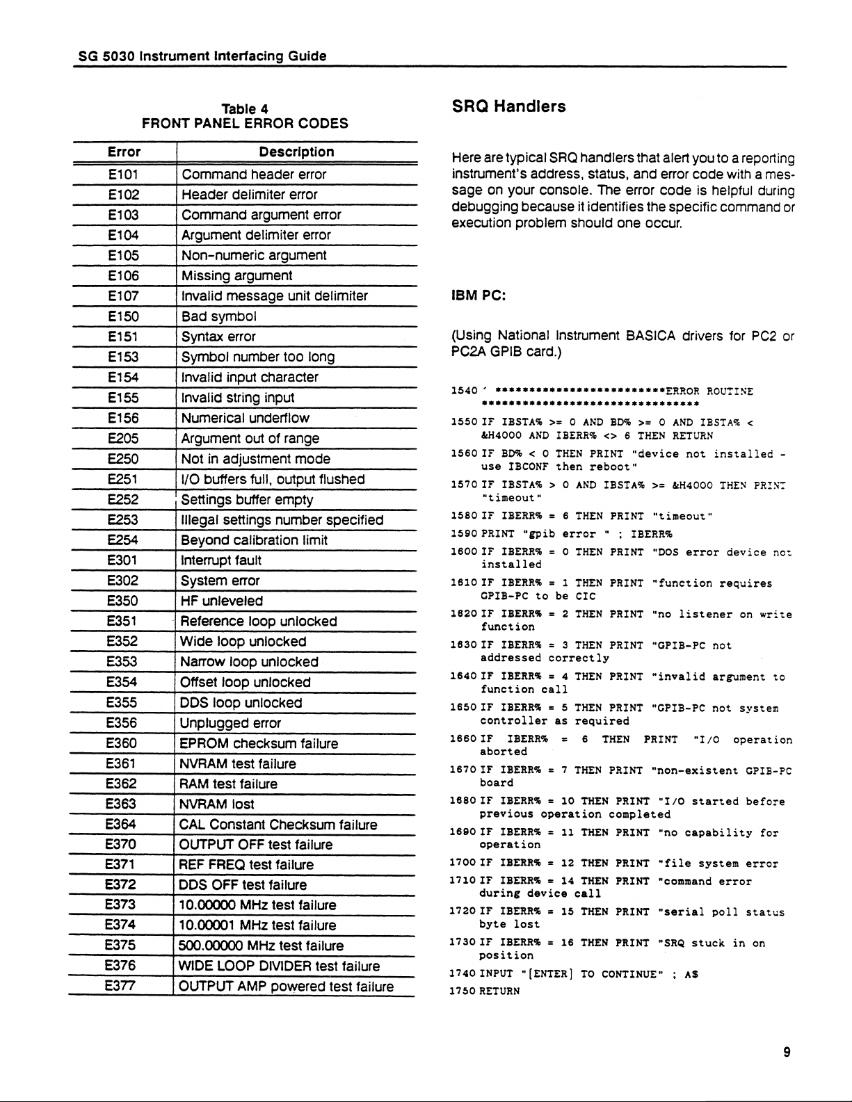
FRONT PANEL ERROR
Error
E101
E102
E103
E104
E105
E106
E107
E150
E151
E153
E154
E155
E156
E205
E250
E251
E252
E253
E254
E301
E302
E350
E351
E352
E353
E354
E355
E356
E360
E361
E362
E363
E364
E370
E371
E372
E373
E374
E375
E376
E377
Command
Argument delimiter error
Non-numeric
Missing argument
Invalid message unit delimiter
Bad symbol
Syntax error
Symbol number too long
Invalid input character
Invalid string input
Numerical underflow
Argument out of range
Not in adjustment mode
\/O buffers full, output flusned
Settings buffer empty
illegal settings number specified
Beyond calibration limit
interrupt fault
System error
HF unleveled
| Reference loop unlocked
Wide loop unlocked
Narrow loop unlocked
Offset loop unlocked
DDS loop unlocked
Unplugged error
EPROM checksum failure
NVRAM test failure
RAM test failure
NVRAM lost
CAL Constant Checksum failure
OUTPUT OFF test failure
REF FREQ test failure
DDS OFF test failure
10.00000 MHz test failure
10.00001 MHz test failure
500.00000 MHz test failure
WIDE LOOP DIVIDER test failure
OUTPUT AMP powered test failure
Table 4
CODES
Description
Command
header error
Header delimiter error
argument error
argument
SRQ Handlers
Here are typical SRQ handlers that alert you to a reporting
instrument's address, status, and error code with a mes-
sage on your console. The error code is helpful during
Gebugging because it identifies the specific command
execution problem should one occur.
IBM
PC:
(Using National instrument BASICA
PC2A GPIB card.)
1540°
1550
1560
1570
1580
1590 PRINT “gpib error “ ;: IBERR%
1600 IF IBERR&%
1610 IF IBERR® = 1 THEN PRINT "function requires
1620 IF IBERR®
1630 IF IBERR% = 3 THEN PRINT “GPIB-PC
1640 IF IBERR%® = 4 THEN PRINT “invalid
1650
1660
i670
1880
1660
1700
1710
i720
1730
1740
1750
*eeeeeeeeeeeeeeeeeeeeeeee
SHREK
IF IBSTA% >= 0 AND BD% >= 0 AND IBSTA% <
&H4000 AND IBERR&% <> 6 THEN RETURN
IF BD% < 0 THEN PRINT "device
use IBCONF then reboot"
IF IBSTA% > O AND IBSTA% >= &H4000 THEN PRINT
"timeout"
IF IBERR% = 6 THEN PRINT “timeout"
IBERR%
IBERR&®
IBERR%
IBERR®&
IBERR&
IBERR&%
IBERR&%
IBERR%
O
= 2 THEN PRINT "no listener
correctly
call
=
as
=
=
operation
=
=
device
=
=
“(ENTER]
installed
GPIB-PC to be CIC
function
addressed
function
IF
controller
IF
aborted
IF
board
IF
previous
IF
operation
IF
IF
IBERR®%
during
IF
byte lost
IF
position
INPUT
RETURN
AERA
THEN PRINT "DOS error device net
5
THEN
required
6
THEN
THEN
THEN
THEN
THEN
call
THEN
THEN
TO
PRINT
THEN
PRINT
completed
CONTINUE”
PRINT
PRINT
PRINT
PRINT
PRINT
PRINT
=
7
10
11
12
14
15
16
REA SEES
"GPIB-PC
PRINT
"non-existent
"I/O
“no
“file
“command
“serial
"SRQ
)
drivers for PC2 or
ERROR ROUTINE
not installed
on
not
argument
not
system
"I/O
operation
GPIB-PC
capability
;
AS
started
stuck
system
poll
error
before
error
status
in
write
for
on
or
-
to
Page 10

SG 5030 Instrument Interfacing Guide
4041:
120 On srq then call dopoll
srq
Enable
130
140 Main program
=!
150
!
970
!
980
990 End
1000 Sub dopoll
1010 Poll stabyt addr
1020 Input #addr prompt "“ERR?":errnum
1030 Print “STATUS=";stabyt,
“ERROR=";errnum
1040 Resume
SG 5030 Response
"ADDRESS=";addr,
to
Interface Messages
The following program sequences show various interface
messages transmitted to the SG 5030.
IBM PC:
(Using National Instrument BASICA drivers for PC2 or
PC2A GPIB card.)
20 ’ SG 5030 PRIMARY
°
130
140 BDS="GPIBO"
150 CALL IBFIND (BDS,BD%)
160 IDS="TEKDEV1"
170 CALL IBFIND (IDS, DEV%)
V%=10
180
190
CALL
IBPAD
200 RETURN
210 CMDS=CHRS
MLA
220 CALL IBCMD (BD%, CMDS)
230 RETURN
240 CMDS=CHRS
250 CALL IBCMD BD%, CMDS)
260 RETURN
270 CMDS=CHRS
280 CALL IBCMD (BD%, CMDS)
290 RETURN
300 CMDS=CHRS
310
CALL
320 RETURN
330 ° SEND DEVICE CLEAR
340
CMDS=CHRS
350
CALL
360
RETURN
370 ° SEND MLA, SELECTED
380 CALL IBCLR (DEV%)
390
RETURN
400 LLOS=CHRS
IBCMD
IBCMD
(V%+32)
(UNL)
(V%+64)
(UNT)
(BD%,
(20)
(BD%,
(17)
(DEV%,V%)
ADDRESS,
° SEND UNLISTEN,
“SEND TALK ADDRESS
° SEND UNTALK
CMDS)
CMDS
DEVICE CLEAR, UNL
°SEND LOCAL LOCKOUT
’CHANGE
°
SEND
10
LISTEN
ADDRESS
ADDRESS,
UNL
.
TO
10
410 CALL IBCMD (BD%,LLOS)
420 RETURN
430 ° SEND MLA, GO TO LOCAL, UNL
440 CALL IBLOC (BD%)
RETURN
450
460 CMDS="? "
TRIGGER,
470 CALL IBCMD (BD%, CMDS)
480 CMDS (8) + "? "
~ 490 CALL IBCHD (BD%, CMDS)
$00 RETURN
UNL
“SEND MLA, GROUP EXECUTABLE
4041:.
40 Pri addr=10
kk
!
150
160 Listen: wbyte atn(pri_addr+32)
Address MLA
170 Return
180 Unlisten:
190 Return
200 Talk: wbyte atn(pri_addr+64)
dress
210 Return
220 Untalk:
230 Return
240 Devclear:
250 Return
260 Selctclr:
270 ! Send MLA, Selected Device Clear, UNL
280 Return
290 Lockout:
300 Return
310 Gt local:
320 ! Send MLA, Go to Local, UNL Trigger,
330 Return
340 Loclstat:
350 ! Pulse unassert
360 Return
!
*** SG 5030 Primary
wbyte atn(unl)
wbyte atn(unt)
wbyte
wbyte sdc(pri_addr)
wbyte
wbyte gtl(pri_addr)
wbyte ren(0),ren(1)
del
!
llo
!
REN line
!
Send Listen
!
Send Unlisten UNL
!
Send Talk Ad-
!
Send Untalk
Send
Device
,atn(unl)
Send
Local
,atn(uni)
Address
Clear
Lockout
UNL
The SG 5030 responds to DCL and SDC by clearing its 1/O
Buffer and any unexecuted setting commands
in
Pending Settings Buffer, along with any errors or events
_
waiting
to
be
reported
(except
power-on).
LLO locks out the operator from restoring local (front-
panel) control when the instrument is under remote
control.
GTL restores local control if the instrument receives the
message
while
listen
addressed.
See the SG 5030 Operators manual for a full discussion of
how the instrument responds to interface messages.
its
10
Page 11

SG 5030 Instrument Interfacing Guide
QuickBASIC
Sample
Utility Program
for IBM PC Compatibles
This program illustrates a method to check oscilloscope
bandwidth with the SG 5030. Read the comment portions
mar SE EESESEF
° geeeesaneeusaseaeeeeee
¢ SSSSSHAST
BY BRUCE VIRELL.
COPYRIGHT
IS PROVIDED
SUPPORTED
THIS SOFTWARE
PERMISSION.
° NOTICE.
° REQUIRED
OSCILLOSCOPE,
THIS PROGRAM REQUIRES
TO THE FACTORY
° PC REQUIREMENTS:
* TEKTRONIX
* IBM 5153 COLOR DISPLAY,OR
(COLOR OR MONOCHROME).
S3FGi00
HIGHER OR MS-DOS 2.02 OR HIGHER.
PROGRAM
TO PROVIDE
METHOD OF IMPLIMENTING
BANDWIDTHS.
OPERATING
CONNECT
THE SG 5030 MUST BE SET FOR FACTORY GPIB PRIMARY ADDRESS
SET THE OSCILLOSCOPE
OUTPUT
OPERATOR
OSCILLOSCOPE
SG
5030
SG
5030
SCREEN.
VARIABLES:
IBINIT1
IBINIT2
SG$ = TEKDEV1,IBCONF
WRTS
RDS
SPACES(xx)
V%
=
BD®
SPR&%
IBSTA®
IBERR&
"
GURU
IBWRT
SE
ESER SES LE REE CES ESR
SKS SSESSSKASAKSRAKSSAKASSTRERSSSASSASRAAASSERSAS
(C) 1988, TEKTRONIX,
ON AN AS IS
BY
TEKTRONIX.
MAY BE REPRODUCED
COPIES MUST INCLUDE THE ABOVE COPY RIGHT AND WARRANTY
EQUIPMENT:
&
PEP 301,IBM
GURU II HARDWARE/SOFTWARE
PURPOSE:
A
SAMPLE OF INSTRUMENT
PROCEDURE:
THE CONTROLLER
TO
CHANNEL
TO
ADJUST THE SG 5030 AMPLITUDE
DISPLAY
OUTPUT
FREQUENCY.
SIGNAL
AMPLITUDE
=
MEMORY
=
IBINIT1
=
=
VALUE
INSTRUMENT
=
V%,
=
II
=
COMMAND
STATUS
=
SENDS
INSTRUMENT
STATUS
ERROR
CALL
RETURNED
=
DIMMENSIONS
FUNCTIONS:
VARIABLE
BYTE
WORD
BIT
COMMANDS
SG
MPD MARKETING,
FSSESEER
5030 SAMPLE
SES SES ES SEE SESE STEP ES ES ESE SE SES FESS PEERS SES SEES SE
MEASUREMENT
2-2-9890
INC. ALL RIGHTS RESERVED.
BASIS WITHOUT WARRANTY
IN
WHOLE OR IN PART WITHOUT
SG
5030, TM 5000 SERIES MAINFRAME,
GPIB CABLING.
THAT THE SG 5030 ADDRESS TO BE SET
DEFAULT
LOCATION
PRIMARY
OF
10
PC,XT,AT,PORTABLE
EQUIVALENT,
A
PROGRAM TO VERIFY OSCILLOSCOPE
VIA GPIB CABLE, TO THE TM 5000 POWER MODULE.
CHANNEL 1 FOR 1V/DIVISION
1.
THE
PROGRAM
(REFER
REACHES
+
3
DRIVER FOR TEKTRONIX
SENT
FROM
STRING
ADDRESS,
PRIMARY
RETURNED
RETURNED
RETURNED
TO
TO
THE
(BASICA
TO
INSTRUMENT
ADDRESS
VIA
VIA
VIA
INSTRUMENT
FIG.1).
OPERATOR
CG
VARIABLE
IBRSP
EACH
OR A
&
BASICA,
COMMANDS
CONFIGURES
4.2
WORKSPACE
VIA
10
EACH
PC, OR COMPATIBLE.
FOR 6 DIVISIONS
THE
MUST
DIVISIONS
IBWRT
REQUESTED
SIZE
ROUTINE
FUNCTION
FUNCTION
OF
COMPOSITE
WITH IBM PC DOS 2.0 OR
WHICH ILLUSTRATES
AND CONNECT THE SG 5030
THE
SG
PROGRAM
PUSH
KEY
ON
-
SIZE(BIB728.M)+SIZE(BIB.M)
INSTRUMENTATION
ROUTINE
VIA
CALL
CALL
of this program for controller requirements and operation.
All or part of this program may be used in your software.
Preliminary information to use this program is detailed
earlier in this guide under Sending Messages
5030.
SG
PROGRAM
ANY KIND, AND IS NOT
THEN
THE
SASHA
THIS SOFTWARE
VIDEO MONITOR
AMPLIFIER
5030
AND
ON
INCREMENTS
(F1)
OSCILLOSCOPE
IBRD
ROUTINE
**8¢8ee040820828222228884282
HESS
PRIOR
A
OF
10.
ASKS
THE
THE
THE
WHEN
THE
STEERER
SESE
)
to
the
Page 12

SG 5030 Instrument Interfacing Guide
‘ IBRD = RETURNS
IBRSP = PERFORMS
‘ IBPAD = CONVERTS
- IBRDF = RETURNS
- REFER TO GURU II DOCUMENTATION
ee SSE ES ESS EEE EERE SESS ES ESSER ESE ES ES ES SESE EES REE ESS ESE ESSE SETS ERS ES SE FE
° GURU II/v PEP 301 INCLUDE GURU CALL FUNCTION
HSSARSSAERSAACASA
PARAMETERS
SERIAL POLL OF INSTRUMENT
IBCONF ADDRESS
INSTRUMENT
FROM INSTRUMENT
PARAMETERS
SASS SSSA
SSAARE SAAR
TO
10
TO
FILE
FOR A COMPLETE LISTING.
LINES IN BASICA PROGRAMS
EAAAT
ESTAS
AESAAE SAREE SEES
COMMON SHARED IBSTA%, IBERR%, IBCNT%
IDS = “TEKDEV1"
CALL ibfind(ID$,
SG% = 10
CALL ibpad(BD%, SG%)
IDS = “GPIBO"
CALL ibfind(IDS,
REMOTES
CALL IBSRE(GP%,
CLS
REPLYS = SPACES(125)
SETS = SPACE$(125)
WRTS = SPACES(125)
RDS = SPACES(125)
BANDWS = SPACES(125)
FREQS = SPACES(16)
=
BD%)
° SELECT TEKDEV1 FOR GPIB ACCESS
‘ SG% = FACTORY DEFAULT ADDRESS OF 10
GP%)
1
REMOTES)
’ CHANGE TEKDEV1 PRIMARY ADDRESS TO 10
° SET UP GPIB FOR BOARD LEVEL
* COMMUNICATION
° SET REMOTE ENABLE
° CLEAR SCREEN
° DIMENSION
° DIMENSION
‘ DIMENSION
* DIMENSION
‘ DIMENSION
° DIMENSION
REPLYS TO 125
SETS TO 125
WRTS TO 125
WRTS TO 125
BANDWS to 125
FREQS TO 16
MAINPROG:
CLS
PRINT
“SSS Se cece cs eeSeSEKTSEKRSESSTKSEKCKASSSSKSKTASKARKSSSKSE
PRINT
"s2eeneseneexcauuezeee
PRINT
“SSS Se eeecs eases
CALL IBWRT(BD%,
GOSUB ERRORGPIB
"“INIT")
SG
5030 SAMPLE
KKKKHSKCSHKSASESSSKSSKSSKTKKKSSKSARSKKSESKSRTKKSEKKRKSEE"
° SEND MESSAGE TO INST
° CHECK GPIB ERROR
PROGRAM
SSR TASSATASKSSESSERESKESE"
**88 e882 eee eaeeeeeeeeaen"
rngval = 50000
ANSFLAG
WRTS = "FREQ “ + STRS(rngval)
CALL IBWRT(BD%,
PRINT : INPUT “WOULD YOU LIKE TO LOG RESULTS
= 0
° PRINTER
+
";OUT ON;"
WRTS)
° SEND MESSAGE TO INST
TO
FLAG
LINE PRINTER?
(Y/N)"; ANSS
IF ANSS = "“y" OR ANSS = "Y" THEN ANSFLAG = 1
PRINT : INPUT "ENTER YOUR NAME"; REPLYS
LOCATE 9, 43: PRINT "MHZ"
LOCATE 9, 1: INPUT “ENTER THE SPECIFIED
PRINT : PRINT “SET SCOPE FOR PRECISELY
INPUT "
PRINT : PRINT “PRESS KEY Fl WHEN SCOPE DISPLAY
KEY(1) OFF: ON KEY(1) GOSUB TERMINATE:
THEN PRESS ENTER TO CONTINUE";
KEY(2) OFF: KEY(3) OFF: KEY(4) OFF: KEY(5) OFF: KEY(6) OFF
KEY(7) OFF: KEY(8) OFF: KEY(9) OFF: KEY(10) OFF
CHECKCG:
IF rngval < 800000 * VAL(BANDWS)
SCOPE BANDWIDTH";
6
DIVS OF SINEWAVE
AS
KEY(1) ON
REACHES 4.2 DIVISIONS"
BANDWS
AMPLITUDE"
THEN rngval = rngval + 5000000
“ENABLE KEY Fi
“DISABLE OTHER KEYS
“DISABLE
IF rngval > 800000 AND rnegval < 990000 * VAL(BANDWS)
THEN rngval = rngval + 500000
IF rngval > 880000 * VAL(BANDWS)
WRITS
=
"FREQ
"
+
STRS(rngval)
CALL IBWRT(BD%,
WRTS)
IF rngval > 1200000 * VAL(BANDWS)
THEN rngval = rngval + 200000
+
"“;OUT
ON;”"
° SEND MESSAGE TO INSTRUMENT
THEN GOTO TERMINATE
FOR T = 1 TO 10000
NEXT
T
OTHER KEYS
12
Page 13

SG 5030 Instrument Interfacing Guide
CHECKCG
GOTO
ERRORGPIB:
IF IBSTA% >= O AND BD% >= 0 AND IBSTA% < &H4000 AND IBERR® <> 6
THEN RETURN’no
IF BD® < O THEN PRINT “device not installed
IF IBSTA% > O AND IBSTA% >= &H4000 THEN PRINT "timeout"
IF IBERR®% = 6 THEN PRINT "timeout"
PRINT "gpib error "; IBERR%
IF IBERR% = O THEN PRINT "DOS error device not installed"
IF IBERR®% = 1 THEN PRINT “function
IF IBERR% = 2 THEN PRINT "no listner on write function"
IF IBERR®% = 3 THEN PRINT "GPIB-PC
IF IBERR% = 4 THEN PRINT "invalid
IF IBERR®% = 5 THEN PRINT "GPIB-PC not system controller
IF IBERR% = 6 THEN PRINT "I/O operation
IF IBERR®&® = 7 THEN PRINT "non-existant
IF IBERR®% = 10 THEN PRINT "I/O started before previous
IF IBERR®%® = 11 THEN PRINT "no capability
IF IBERR% = 12 THEN PRINT "file system error"
IF IBERR® = 14 THEN PRINT “command
IF IBERR®% = 15 THEN PRINT "serial poll status byte lost"
IF IBERR% = 16 THEN PRINT "SRQ stuck in on position"
INPUT " (ENTER | TO CONTINUE"; AS’ if helpS then
RETURN
TERMINATE:
CALL IBWRT(BD%,
CALL IBRD(BD%,
SETS
CALL IBWRT(BD%,
CALL IBRD(BD%,
FREQS = LEFTS(RDS,
IF ANSFLAG = 0 THEN GOTO SCREENPRT:
LPRINT
LPRINT : LPRINT "OPERATOR
LPRINT
LPRINT : LPRINT "SG 5030 SETTINGS:"
LPRINT
LPRINT
LPRINT
LPRINT
SCREENPRT
PRINT:
PRINT
PRINT
LOCATE
PRINT
LOCATE
INPUT
IF
RUNTESTS
PRINT
END
°
¥#€ KEES KREKRKKKEEREK
error to report
°
*#4*e4ee4ee4"2ee"00
"SET?")
RDS)
=
RDS
SETS
FREQS
REPLYS
SETS
FREQS,
PRINT
:
21,
22,
"
"
:
:
PRINT
LPRINT
"FREQ?")
RDS)
,
"SCOPE
"MHZ"
"SG
1:
PRINT
19:
PRINT
=
"Y"
5030
OR
-
16)
"SCOPE
"MHZ"
RUNTESTS
BANDWIDTH:
SETTINGS"
NAME:”
BANDWIDTH"
=
FRROR ROUTINE
requires GPIB-PC to be CIC”
not addressed
argument
aborted"
GPIB-PC board"
error during
TERMINATE
‘ TEST FOR LINE PRINT REQUEST
‘ OPTIONAL
"
°
RUN
TEST
"y"
THEN
PROGRAM
888 KEKEREREKEEKAEKKEEKEKEKREKS
-
use IBCONF then reboot"
correctly”
to
function
for operation”
device call"
PROGRAM
° SEND MESSAGE
° SEND MESSAGE
PRINT
GOSUB
AGAIN?
MAINPROG
TERMINATED.
TO
call"
as
required"
operation
*** #8 Re RRR EERR EKER
TO
INST
TO
INST
LINE PRINTER OUTPUT
SCREEN
INFORMATION
(Y¥/n)";
RUNTESTS
"
completed"
EEK
13
Page 14

SG 5030 Instrument Interfacing Guide
rrr
Ln
ic
a
ores
a
ee
A. Set SG 5030 output amplitude for 6 vertical divisions of
display.
amplitude
a
>
>
>
>
>
»
,
>
oscilloscope
the
on
kHz
50
at
:
°
as
Pte
PUN
AEP RY
.
et Bd
hel
tk
Le
“wh anyrn
w¥e
Ea
2
MAC
»
".¢uaawe:
sae
hr
oe
a
oe
aT
Poe.
Pe Se+ hd
vERSKAIER ADS
EOD
ATS
CMS
ave Aer 4
wes cea
” ee
VRB
ee
7
er ” wwe
ROMY AY ‘ . os
TONMMO
.
the
3we
Law
an
ra
aS
RAR
“eRe
3
:
.
Se
ce. «
<
te
Beata s
xrey ne
a)
oe
20
ne
xy
ats
he
av
ore
~y
tae
an
a.)
oe
we
es
Ra
ne
.
ey
‘+m
aurwen-
car
°
.
.
.
+
.
—eew
. Increase the SG 5030 frequency until the displayed
waveform amplitude drops to 4.2 vertical divisions. This
frequency reflects the bandwidth of the oscilloscope, also
known as the -3 dB point.
Figure 1. Waveform results of the SG 5030 Sample Measurement
Program.
7704-1
14
Page 15

SG 5030 Instrument Interfacing Guide
QuickBASIC
Program
Talker/Listener
For IBM PC Compatibles
Utility
This program allows the user to send any of the instru-
ment commands
command
4 SRERSRSAE
to
the SG 5030. It is useful in learning the
set and in software debugging.
ERATE EERE
ERATE
RSET EARS HES RE SSAA
RAS ESSERE
REESE
‘ gaeeeenaeeaeeeaeex SG 5030 TALKER/LISTENER PROGRAM *#8eeeaaeeaseeeesenens
4 SRSA
° THIS PROGRAM REQUIRES
‘ FACTORY DEFAULT OF 10
COMMON SHARED IBSTA%.
IDS = "TEKDEV1"
CALL IBFIND(IDS,
SG% = 10
CALL IBPAD(BD%,
ID$ = "GPIBO”
CALL IBFIND(IDS,
REMOTES = 1
CALL IBSRE(GP%,
CLS
REPLYS = SPACES(125)
PRINT
PRINT
PRINT
MAINPROG:
PRINT “RETURN TO EXIT: "
INPUT "ENTER MESSACGE(S)";
IF WRTS = "" THEN GOSUB TERMINATE
CALL IBWRT(BD%,
GOSUB CHECKGPIB
SRSSTASSAKSEKHAEKRAKTSEKASE
FOR T = 1 TO 1000
NEXT T
CALL IBRD(BD%,
GOSUB
CHECKCG
PRINT
PRINT : PRINT "Returned
PRINT
GOTO
©
CHECKCG:
ERRMS = SPACES(S50)
CALL IBRSP(BD%,
CALL
CALL
RETURN
CHECKGPIB:
IF
RETURN’no
IF
IF
IF
SERA
“RESETS
"“s"eeenenenenwneeee
“SS Se eee ee ee eee Skee
CHECKGPIB
:
:
MAINPROG
SSSSSTVSKVSSCc_s#e#e
IBWRT(BD%,
IBRD(BD%,
IBSTA%
BD%
IBSTA%
IBERR%
<
PRINT
PRINT
O
>=
error
>
=
THEN
0
O
6
SSAA
IBERR%,
BD%)
SAAR
AERA TEER
THAT THE SG 5030 ADDRESS BE SET TO THE
IBCNT%
‘ SELECT TEKDEV1 FOR GPIB ACCESS
' SG% = FACTORY DEFAULT ADDRESS OF 10
SG%)
GP%)
REMOTE%)
TKSAKKSKHRATTCKLSESTCHCKCSHSTSSKSKASTTACKTKKSCVSSTCCCKKCSASESEKKKRKKSEKAKEKRAEKERE
SG
5030 TALKER
KASRESKSSAARSRSERERSATAAAAKTASARRERARERE
WRTS
WRTS)
INPUT
REPLYS)
“INSTRUMENT
REPLY
status byte:";
ERRMS
ese
AND
THEN
ERRMS)
AND
SPR%)
“ERR?")
to
PRINT
ecceae#ses
IBSTA%®
BD®%
report
PRINT
>=
“device
anne
O
AND
>=
&H4000
“timeout”
ERROR
not
‘ CHANGE TEKDEV1
’ SET UP GPIB FOR BOARD LEVEL
* COMMUNICATION
’ SET REMOTE ENABLE
‘ CLEAR SCREEN
‘ DIMENSION
LISTENER
° SEND MESSAGE TO SG 5030
° CHECK FOR GPIB ERROR
FROM
DEVICE
° INPUT DATA FROM SG 5030
°“
CHECK
°
GET
SG
“,
REPLYS
SPR&%,
IBSTA%
ROUTINE
installed
THEN
<
&H4000
PRINT
STETCARTESTKAVSKRCCKTCECKABTCCCVW
AAAS ESSERE
PRIMARY
RDS TO 125
PROGRAM
SVWSSEASSETCKCTCCTLKCKCKKETCSCEKRERKRAVKSKES
FOR
GPIB
ERROR
5030
ERROR
AND
IBERR%
-
use
IBCONF
“timeout”
****ee02eeeunane"
GOSUB
MESSAGE
<>
then
ADDRESS
6
THEN
reboot”
EERE
see
ERED
TO
KARE E
eeae
EHD
10
15
Page 16

SG 5030 Instrument Interfacing Guide
PRINT “gpib error "; IBERR%
THEN
PRINT
IBERR®
IF
IF
IBERR%
IF
IBERR%
IBERR®
IF
=
IBERR®
IF
IF
IBERR%®
IF
IBERR%
IF
IBERR%
IF
IBERR%
IBERR%
IF
IF
IBERR®
iF
IBERR%
IF IBERR%
IF IBERR® = 16
INPUT “(ENTER ]
RETURN
rd
SSRSTHSSR
TERMINATE:
REMOTE®
CALL IBSRE(GP%,
PRINT
END
=
"PROGRAM
ASA
0
THEN
THEN
THEN
THEN
THEN
THEN
“VO
MWbh
WwW
WOFFOO
THEN
THEN
THEN
THEN
THEN
oe
ee
|
ee
©
ee
ObWo
FH
O
THEN
THEN
TO
CONTINUE"
SS
Eee
REMOTE)
TERMINATED."
"DOS error device not installed"
PRINT
"function
PRINT
"no listner on write function"
PRINT
“GPIB-PC
PRINT
“invalid argument to function call"
PRINT
“GPIB-PC
PRINT
"I/O operation
"non-existant
PRINT
PRINT
PRINT
PRINT
PRINT
PRINT
PRINT
"I/O
"no
“file system error"
“command
"serial
“SRQ
AS’
;
eee
eee
TERMINATE
started
capability
stuck
requires
not addressed
not
error
poll
if
help$
in
PROGRAM
e
system
GPIB-PC
before
status
CLEAR
GPIB-PC to be CIC"
correctly"
controller
aborted"
board”
previous
for
operation"
during
device
byte
on
position"
then
8888S
Se
REMOTE
lost"
SERRE
ENABLE
operation
call"
as
required"
SEREEEREE
completed"
REESE
16
Page 17

SG 5030 Instrument Interfacing Guide
87
g
BE
BITS
B4B8382B1
gee@s6|
g 3 # 11 SOH |
gss31s8i STX | DC2
gs11|
g9 18 91 EOT | DC4
s 1911 ENQ | NAK
e111
s 111] BEL | ETB
12951
16681]
1619]
1g11]
119 3| FF | FS
11911
11191
114171
g¥
B5
5 f
CONTROL
0
NUL | DLE | SP
0
0} 10
1
GTL
1
149
2
2
24,12
3
ETX | DC3
3
3713
4 SOC | 24 OCL § 44
4
a} 14 20 § 24
5 PPC | 25 PPUT4S ~~ § 165 21 8
§
§41§
6
ACK | SYN
6
6 | 16 22 5 26
?
?
747
fe) GET | SPE 450 8 |70 248310
BS | CAN|
8
6} 18 244 28
1 TCT | 31 SPO #5!
HT
9
9};19
12
LF | SUB]
A
10} 1A
13
VT | ESC]
8
114198
14
Cc
12 [1C 28 § 2C
1§
CR | GS { —- | = | M
0
13} 10
16
SO
E
14} 1E 308 2E
17
SI
F
S|] IF 37 § 2F
AOORESSED UNIVERSAL
COMMANOS COMMANOS
pf
B
gS
1
S
1
g
1
1
A
1
1
3
g
1
NUMBERS
SYMBOLS
20
j
21
DC1
22
23
26
27
32
3x
34
35
36
37
40
41
42
43
%
46
4?
$2
$3
$4
$5
56
S7
!
"
+
$
&
,
(
)
*
+ | ;
;
.
VA
USTEN
ADORESSES
16 § 20
LLOG
17921
18 § 22
19 § 23
21425
23 9 27
EM
25 § 29
26 § 2A
27428
29 82D 45 }30 61 840 77 | 50 93 7 60 109 | 70 128
RS
US
UPPER CASE
0 | 60 16 § 100
0
32 | 30
1
161
1
33 {31
2 | 62
2
34 132 50 #42 66 | 52
3 {63 19 § 103
3
3§ [3
4 {64 20 § 104
4
36 134 52 944 68 | $4
5
37 135 §3 945 69} 55
6
(66
6
38 (36 $4946
7 167 23 §
7
39 {37 §§ 947 711 §7
8
40 138 $6 938 72 | 58
9 }71
9
41 |39 §7 949 73 | 59
10 | 72
:
42 13A
14/73
43 (38 $9 #46 78 | 58 914968
12 | 74
<
44 13C 60 €4C 76 | SC 928 6C 108 17C 124
13 {75 298115
489 40
178101
4a9ici
18 § 102
§1 943 67} $3
22
§
28 9121
26g '12 10] 132 268 152 10 1} 172 26
58 E4A
27 9113 117133
28 8114 12 |
0| 120 16 140
@
64; 50
A
65} 51
2] 122 168 142
B
3] 123 198 143
Cc
41 124 208 144
D
105
§} 125 218 148
E
106
6
F
70 | $6
107
7 | 127 238 147
G
8}
H
9} 131 258 151
I
J
7415A
K
L
13] 138 298 185 13 | 175 29
14 176 30 #116 14) 136 A 30 §
>
N
Oo
ADORESSES
79 | SF
TALK
46 }3E 62 94E 761 SE 949 6E 110 | 7E 126
1§ 177 UNL 9117 1§ 1 137 UNT @
?
47 |3F 63 § 4F
P
80 § 60
121
170
Q
818 61
R
825 62
S
83963
T
845 64 100 | 74 116
U
8S4 65 101 175 117
|
126
22
§
"4
86 § 66 102 | 76 118
Ww
87 § 67 103 | 77 119
190 248 150
X
68 § 68 104 | 78 120
Y
89 769 105 179 121
Zz
90
§ 6A
278 °S3 wt 4173 27
[
134 28 § 154 12 | 174 28
\
] | m
—
95 8 6F 149 1 7F 127
1
1
1
1
B
LOWER CASE
0 |
160 16
>
141
a
b
3 |
c
4 |
d
§ |
e
146
f
7
g
8 | 170 26
h
i
j
k
I
156 141176 n~ 30
p
96 | 70 112
1
{161
q
97 | 71 113
2} 162 18
r
98 | 72 114
163 19
Ss
99 173 115
164 20
t
165 21
u
6
|
166
Vv
1167 23
w
x
94175
y
z
106 {7A 122
{
107 | 78 123
}
|
n
157 1§ [177 OEL
ce )
(RUBOUT)
SECONDARY ADORESSES
OR COMMANOS
1
17
22
25
|
KEY
octal 125
TEKTRON(X STD 062-5435-00 4 SEP 80
COPYRIGHT © 1979.
hex 115
{
PPU 1 GPIB code
N AK
ASCII character
211 decimal
1980 TEKTRONIX. INC. ALL RIGHTS RESERVED
Figure 2. ASCII and IEEE (GPIB) Code Chart.
Tektronix
REF: ANSI STD X3. 4-1977
IEEE STO 488-1978
ISO
STD
646-1973
®
we
7703-8
17
Page 18

SG 5030 Instrument Interfacing Guide
TEKTRONIX
INSTRUMENTATION
Tekware
Tektronix Instruments
Controllers
With technology
becoming
measurement
Tek can meet your need for improved test and measure-
ment productivity in the lab, on the factory floor, or at the
remote site. Tekware programs are designed to enhance
the productivity of Tektronix instruments and controllers.
Tektronix has performed extensive software testing to
verify that all standard Tekware measurement,
and utility packages run reliably with Tek instruments and
controllers. MS-DOS
tested for compatibility with 286/386 IBM compatible PC
system controllers.
Programs
more complex
shorter, the need to automate test and
environments is greater than ever.
Complement
an
Tekware programs
and_ schedules
have been
analysis,
SOFTWARE
LIBRARY
Software Support
To keep your software current and up-to-date, our soft-
ware support is available at no charge during the
warranty period. Post-warranty software support is avail-
able on a subscription basis.
Technical Assistance
When you need technical assistance to supplement your
own resources, Tektronix can provide the services of an
Applications Engineer skilled in meeting your needs. For
more information contact your local Tektronix Field office.
Tektronix Test Management
Services (TAS)
System
(TEKTMS)
TekTMS provides a highly productive software package
for test development
repair/rework, and prototype development
applications.
and execution in manufacturing,
testing
Applications
Tekware applications software provides a wide selection
of ready-to-use
and display capabilities. Simply load Tekware appli-
Cations into your controller, and your system is ready to
go to work for you. If your software requirements do not
Call for unique processing
functions,
shortest path to a complete system solution.
Development
Tekware
create
Tekware
program
cedures
if
custom
a
the
your
Tekware
solution.
development
new
development
without
testing
program
Tekware
software
generators
requirements
development
Software
general purpose control, measurement,
or
applications
Software
or
writing
or
for
software
to
modify
software
enabling
a
single
customizing
software
call
software
tools
existing
products
you
line
for
an
tool
specialized
can
software.
to
create
of
code.
development
existing
could
could
be
be
contain
test
program,
the
control
be
used
Some
key
the
test
pro-
of
EZ-TEST
Test Development
Software
EZ-TEST is a software productivity tool used to create
and run test software for manufacturing, service
and rework, metrology, and prototype evaluation.
EZ-TEST is for non-programmers
prefer to concentrate on testing rather than software
coding chores.
The EZ-TEST software system provides
necessary to develop and run test systern programs. The
major elements of EZ-Test are:
— Generator program to create, debug, and execute
the test procedure.
to
a
to
—
Translator
Microsoft QuickBASIC
link
program.
— Test Execution Scheduler to run sequences of com-
piled
—
Microsoft
manuals.
it,
tests
program
resulting
and
QuickBASIC
gather
to
in
a
test
or
convert
code and
complete
data.
editor,
compiler,
programmers who
all
the
procedure
then compile and
stand-alone
— GPIB interface software for QuickBASIC.
repair
the software
test
linker
and
to
18
Page 19
SG 5030 Instrument Interfacing Guide
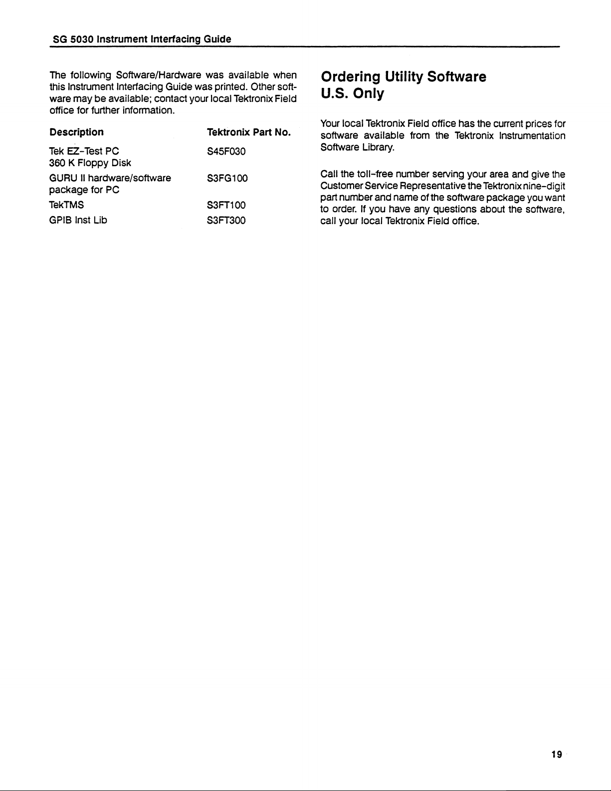
The following Software/Hardware
this Instrument Interfacing Guide was printed. Other soft-
ware may be available; contact your local Tektronix Field
Office for further information.
Description
Tek EZ-Test PC
360 K Floppy Disk
GURU II hardware/software
package for PC
TekTMS
GPIB Inst Lib
was available when
Tektronix Part No. |
S45F030
S3FG100
S3FT100
S3FT300
Ordering Utility Software
U.S. Only
Your local Tektronix Field office has the current prices for
software available from the Tektronix Instrumentation
Software Library.
Call the toll-free number serving your area and give the
Customer Service Representative the Tektronix nine-digit
part number and name of the software package you want
to order. If you have any questions about the software,
call your local Tektronix Field office.
19
Page 20

Copyright© 1990 by Tektronix, inc., Beaverton, Oregon. All rights reserved. Printed In the United States of America. The information presented In this document is
purposes only. Tektronix, Inc.. does not warrant or represent
MPD Marketing Applications Support Group.
in any way the accuracy or completeness of any program herein or Its fitness for a user's particular purpose. Produced by the
provided for instructional
 Loading...