

Page 1

www.keithley.com
Series 3700 System Switch/Multimeter
Quick Start Guide
3700S-903-01 Rev. C / November 2008
G
A
T
E
E
A
R
AEM
R
E
RUS
C F
O
IF
NO
ECNED
Page 2

Page 3

WARRANTY
Keithley Instruments, Inc. warrants this product to be free from defects in material and workmanship for a period of
one (1) year from date of shipment.
Keithley Instruments, Inc. warrants the following items for 90 days from the date of shipment: probes, cables,
software, rechargeable batteries, diskettes, and documentation.
During the warranty period, Keithley Instruments will, at its option, either repair or replace any product that proves
to be defective.
To exercise this warranty, write or call your local Keithley Instruments representative, or contact
Keithley Instruments headquarters in Cleveland, Ohio. You will be given prompt assistance and return instructions.
Send the product, transportation prepaid, to the indicated service facility. Repairs will be made and the product
returned, transportation prepaid. Repaired or replaced products are warranted for the balance of the original
warranty period, or at least 90 days.
LIMITATION OF WARRANTY
This warranty does not apply to defects resulting from product modification without Keithley Instruments’ express
written consent, or misuse of any product or part. This warranty also does not apply to fuses, software,
non-rechargeable batteries, damage from battery leakage, or problems arising from normal wear or failure to follow
instructions.
THIS WARRANTY IS IN LIEU OF ALL OTHER WARRANTIES, EXPRESSED OR IMPLIED, INCLUDING ANY
IMPLIED WARRANTY OF MERCHANTABILITY OR FITNESS FOR A PARTICULAR USE. THE REMEDIES
PROVIDED HEREIN ARE BUYER’S SOLE AND EXCLUSIVE REMEDIES.
NEITHER KEITHLEY INSTRUMENTS, INC. NOR ANY OF ITS EMPLOYEES SHALL BE LIABLE FOR ANY
DIRECT, INDIRECT, SPECIAL, INCIDENTAL, OR CONSEQUENTIAL DAMAGES ARISING OUT OF THE USE
OF ITS INSTRUMENTS AND SOFTWARE, EVEN IF KEITHLEY INSTRUMENTS, INC. HAS BEEN ADVISED IN
ADVANCE OF THE POSSIBILITY OF SUCH DAMAGES. SUCH EXCLUDED DAMAGES SHALL INCLUDE, BUT
ARE NOT LIMITED TO: COST OF REMOVAL AND INSTALLATION, LOSSES SUSTAINED AS THE RESULT OF
INJURY TO ANY PERSON, OR DAMAGE TO PROPERTY.
A G R E A T E R M E A S U R E O F C O N F I D E N C E
Keithley Instruments, Inc.
Corporate Headquarters • 28775 Aurora Road • Cleveland, Ohio 44139
440-248-0400 • Fax: 440-248-6168 • 1-888-KEITHLEY (1-888-534-8453) • www.keithley.com
3/07
Page 4

Page 5

The following safety precautions should be observed before using this product and any associated instrumentation. Although some
instruments an d accessorie s would n ormally be used with non-h azardous voltag es, there are situ ations where h azardous conditions ma y
be present.
This product is inte nded for us e by qualifi ed person nel who recognize s hock haz ards and are f amiliar w ith the safe ty precau tions requ ired
to avoid possible in jury. Read and follow all inst alla tio n, opera tion, an d mai ntenance i nfo rmatio n carefu lly b efore us ing the product. Refer
to the user documentation for complete product specifications.
If the product is used in a manner not specified, the protection provided by the product warranty may be impaired.
The types of product users are:
Responsible body is the individual or group responsible for the use and maintenance of equipment, for ensuring that the equipment is
operated within its specifications and operating limits, and for ensuring that operators are adequately trained.
Operators use the product for its inten ded function. T hey must be trained in ele ctrical safety procedures a nd proper us e of the inst rument.
They must be protected from electric shock and contact with hazardous live circuits.
Maintenance personnel perform routine procedures on the product to keep it op era tin g p r op erly, for example, settin g the li ne v oltage or
replacing consuma ble ma terials . Main tenanc e proc edures are descri bed in t he u ser docum ent ation. The proced ures expl icitly st ate if th e
operator may perform them. Otherwise, they should be performed only by service personnel.
Safety Precautions
Service personnel are trained to work on live circ uits, perform safe installa tions, and repair products. Only proper ly trained service
personnel may perform installation and service procedures.
Keithley Instruments products are designed for use with electrical signals that are rated Measurement Category I and Measurement
Category II, as described in the International Electrotechnical Commission (IEC) Standard IEC 60664. Most measurement, control, and
data I/O signals are Measurement Ca tegory I and must not be dire ctly connected to ma ins voltage or to vo ltage sources wi th high transient
over-voltages. Measurement Category II connections require prote ction for high transient over-voltages often as sociated with local AC
mains connect ions. Assume all measurement, co ntrol, and dat a I/O connec tions are for c onnection to Cate gory I sources unless otherwise
marked or described in the user documentation.
Exercise extreme caution when a shock hazard is present. Lethal voltage may be present on cable connector jacks or test fixtures. The
American National Standards Institute (ANSI) states that a shock hazard exists when voltage levels greater than 30V RMS, 42.4V peak,
or 60VDC are present. A good safety practice is to expect that hazardous voltage is present in any unknown circuit before measuring.
Operators of this product must be protected from electric shock at all times. The responsible body must ensure that operators are
prevented acces s and/or insul ated from ev ery connect ion point . In some c ases, conne ctions mus t be expos ed to potenti al human c ontact.
Product operators in th ese ci rcu ms t ances must be train ed t o protect themselves from th e ri sk of electric shock. If the ci rcu it is capable of
operating at or above 1000V, no conductive part of the circuit may be exposed.
Do not connect switc hing cards direc tly to unlimite d power circui ts. They ar e intended to b e used with im pedance-limite d sources. NEVER
connect switching cards directly to AC mains. When connecting sources to switching cards, install protective devices to limit fault current
and voltage to the card.
Before operating an instrument, ensure that the line cord is connected to a properly-grounded power receptacle. Inspect the connecting
cables, test leads, and jumpers for possible wear, cracks, or breaks before each use.
11/07
Page 6

When install ing equipment where access to the main power cord is r estricted, such as rack mo unting, a separate main in put power
!
disconnect device must be provided in close proximity to the equipment and within easy reach of the operator.
For maximum safety, do not touch the product, test cables, or any other instruments while power is applied to the circuit under test.
AL W AYS remove power from the entire test system and d ischarge an y capaci tors before: c onnecting or disconnect ing cables or jumpers,
installing or removing switching cards, or making internal changes, such as installing or removing jumpers.
Do not touch any o bject that could pro vide a curren t p ath to the com mon sid e of the circ uit under t est or p ower line (e arth) ground . Always
make measurements with dry hands while standing on a dry, insulated surface capable of withstanding the voltage being measured.
The instrument and accessories must be used in accordance with its specifications and operating instructions, or the safety of the
equipment may be impaired.
Do not exceed the maxi mum s ignal levels of the ins trume nts and a ccesso ries, as define d in the sp ecifi cation s and op erat ing info rmation,
and as shown on the instrument or test fixture panels, or switching card.
When fuses are used in a product, replace with the same type and rating for continued protection against fire hazard.
Chassis connections must only be used as shield connections for measuring circuits, NOT as safety earth ground connections.
If you are using a test fixture, keep the lid closed while power is applied to the device under test. Safe operation requires the use of a lid
interlock.
If a screw is present, connect it to safety earth ground using the wire recommended in the user documentation.
The symbol on an instrument indicates that the user should refer to the operating instructions located in the user documentation.
The symbol on an instrument shows that it can source or measure 1000V or more, including the combined effect of normal and
common mode voltages. Use standard safety precautions to avoid personal contact with these voltages.
The symbol on an instrument shows that the surface may be hot. Avoid personal contact to prevent burns.
The symbol indicates a connection terminal to the equipment frame.
If this symbol is on a product, it indicates that mercury is present in the display lamp. Please note that the lamp must be properly
disposed of according to federal, state, and local laws.
The WARNING heading in the user documentation explains dangers that might result in personal injury or death. Always read the
associated information very carefully before performing the indicated procedure.
The CAUTION heading in th e u se r do cu me ntation explains hazards that could damage the instrum ent . Su ch damage may invalidate the
warranty.
Instrumentation and accessories shall not be connected to humans.
Before performing any maintenance, disconnect the line cord and all test cables.
T o main tain protecti on from electric sho ck and fire, replacem ent component s in mains circu its - includi ng the power transform er, tes t leads,
and input jacks - must be purchased from Keithley Instruments. Standard fuses with applicable national safety approvals may be used if
the rating and type are the same. Other components that are not safety-related may be purchased from other suppliers as long as they
are equivalent to the original component (note that selected parts should be purchased only through Keithley Instruments to maintain
accuracy and function ality of the product). If you ar e unsure about the applicabi lity of a replacement co mponent, call a Keithley Ins truments
office for information.
To clean an instrument, use a damp cloth or mild, water-based cleaner. Clean the exterior of the instrument only. Do not apply cleaner
directly to the instrumen t or allow liqui ds to enter or spi ll on the inst rument. Produ cts tha t consist of a circ uit board with no case or chassis
(e.g., a data acquisition board for installation into a computer) should never require cleaning if handled according to instructions. If the
board becomes contaminated and operation is affected, the board should be returned to the factory for proper cleaning/servicing.
Page 7

Quick Start Guide
Series 3700
System Switch/Multimeter
©2008, Keithley Instruments, Inc.
Cleveland, Ohio, U.S.A.
All rights reserved.
Any unauthorized reproduction, photocopy, or use the information herein, in whole or in
part, without the prior written approval of Keithley Instruments, Inc. is strictly prohibited.
TM
TSP
, TSP-LinkTM, and TSP-NetTM are trademarks of Keithley Instruments, Inc. All
Keithley Instruments product names are trademarks or registered trademarks of Keithley
Instruments, Inc. Other brand names are trademarks or registered trademarks of their
respective holders.
Document number: 3700S-903-01 Rev. C / November 2008
Page 8

Introduction
This Quick Start Guide describes how to establish a direct connection between a personal computer (PC)
and the Model 3706, 3706-NFP, or 3706-SNFP System Switch/Multimeter. To make the best use of this
document, you will need the following accessories:
• 1 LAN crossover cable (supplied with Models 3706-NFP and 3706-SNFP)
• LXI
This document demonstrates automatic TCP/IP addressing (also known as Auto IP) on a PC with
Microsoft® Windows® operating system.
Troubleshooting
Auto IP, review the Network Connection Tutorial for Ethernet-Based Instruments located on
www.keithley.com.
NOTE Before attempting to connect the Series 3706 mainframe to a corporate or public network,
TM
Discovery Browser (software provided on the Series 3700 System Switch/Multimeter Product
Information CD, or at www.keithley.com)
Appendix A: Static IP address LAN connection and Appendix C:
contain additional information on static TCP/IP addressing. For more information about
contact your network administrator for your specific network requirements. This guide contains
instructions for necessary DHCP configuration and static IP address assignments.
2 3700S-903-01 Rev. C / November 2008
Page 9

Using the Quick Start Guide
This guide summarizes basic measurement functions and a few of the important features of the Keithley
Instruments Series 3700 System Switch/Multimeter instruments. Note that only certain front-panel
controls are described in this guide; for more detailed information, refer to the Series 3700 System
Switch/Multimeter User's and Reference Manuals. The following table identifies topics applicable to your
model.
Topic
Hardware and software
requirements
Connection warning
Install the module
Using the navigation wheel and
display
Remote operation
Front panel procedures
- Common tasks
- DMM operation versus switch
operation
- Advanced applications
- Using the Analog backplane
3706
with module
3706-S
with module
connector to take measurements
without a switch module
Troubleshooting
3706
without module
3706-S
without module
3706-NFP
with module
3700S-903-01 Rev. C / November 2008 3
Page 10

Hardware and software requirements
The following table defines the hardware and software requirements using in the examples in this Quick
Start Guide.
DMM vs. switch
operation
(1) Multiplexer
Module 60
installed in Slot 1
DC power supply
or battery;
connected across
channel
(1) Resistor
Range from 1 Ω to
120 MΩ
PC with network
interface card
(NIC) and TCP/IP
protocol installed
PC with JAVATM
Platform,
Standard Edition 6
installed
USB flash drive
Advanced
application
Analog backplane Remote
operation
NOTE Multiplexer switch modules include (but are not limited to) Models 3720, 3721, 3722, and 3723.
4 3700S-903-01 Rev. C / November 2008
Page 11

Connection warning
WARNING Connection information for switching modules is intended for qualified service
personnel. Do not attempt to connect DUT or external circuitry to a switching
module unless qualified to do so.
To prevent electric shock that could result in serious injury or death, comply with
these safety precautions:
Before making or breaking any connections to the switching module, make sure
the Series 3700 is turned off and power is removed from all external circuitry.
Do not connect signals that will exceed the maximum specifications of any
installed switching module.
Test lead insulation must be rated to the highest voltage connection when the
Series 3700 rear analog backplane connector and the switching module terminals
are simultaneously connected. For example, if 300V is connected to the analog
backplane connector, the test lead insulation for the switching module must also
be rated for 300V.
Dangerous, explosive electrical arcs that can cause severe personal injury or
death are possible if a multimeter that is set to a low-impedance range is
connected to a high-energy circuit, causing a "virtual short."
Dangerous arcing can result (even when the multimeter is set to a voltage range) if
the minimum voltage spacing is reduced in the external connections. For details
about how to safely make high energy measurements, see High-energy circuit
safety precautions in the Series 3700 Reference Manual.
IMPORTANT: Do not connect the Series 3700 to mains; it is designated Installation
Category I, as described in the International Electrotechnical Commission (IEC)
Standard IEC 664.
3700S-903-01 Rev. C / November 2008 5
Page 12

Install the module
WARNING Slot covers must be installed on unused slots to prevent personal contact with
high-voltage circuits.
Figure 1: Typical module installation
(1) Card guide (part of Series 3700) (3) Card edge (part of module)
(2) Module (4) Mounting screw (part of module)
WARNING To prevent electric shock that could result in injury or death, NEVER handle a
switching module that has power applied to it.
Before installing (or removing) a switching module, make sure the Series 3700 is
turned off and disconnected from line power.
If the switching module is already connected to a device under test (DUT), make
sure power is removed from all external circuitry.
6 3700S-903-01 Rev. C / November 2008
Page 13

Using the navigation wheel and display
The navigation wheel makes it easy to move through the menus and set parameters. You will use a
combination of turning and pressing the wheel to maneuver through the menus and configuration choices.
Highlight the parameter you want to select or configure and push the navigation wheel to accept the
parameter. Pushing the navigation wheel has the same functionality as pressing the instrument front
panel ENTER key.
To maneuver within the active channel display:
• Pushing the navigation wheel has the same functionality as the Tab key on a PC. Each push of the
navigation wheel sequentially moves the selection through the four main display parameters: slot,
channel, end channel, and measurement function.
To configure a parameter in the active channel display:
• Push the navigation wheel until the desired parameter is highlighted: slot, channel, end channel, or
function.
• Rotate the navigation wheel to scroll to the desired measurement function or to edit the value of the
numeric parameter of the slot, channel, or end channel. Slot parameters are not configurable unless a
module is installed in that slot position.
• Push the navigation wheel or press the ENTER key to accept your changes.
To configure a parameter within a menu:
• Press the MENU key to enter the desired menu.
• Rotate the navigation wheel to scroll to the desired parameter (indicated by BOLD in the procedures
shown in this guide).
• Push the navigation wheel or press the ENTER key to accept your changes. Note that this action is
indicated as > in this guide.
• Press the EXIT key to return to previous layer of the menu.
3700S-903-01 Rev. C / November 2008 7
Page 14

Front-panel display
Figure 2: Example of active channel display
(1) Measurement function attributes (for
(4) Measurement function attributes.
example, auto range).
(2) Slot and active channel. Also start
(5) Indicates additional attributes are
channel of scan list.
(3) The present state of channel attributes.
Also end channel of scan list.
(6) Navigation wheel.
Figure 3: Example of MAIN MENU display
available for access by turning the wheel.
8 3700S-903-01 Rev. C / November 2008
Page 15

Remote operation
Factory defaults for the communication port settings:
LAN
• Method = Auto (DHCP and auto-IP enabled)
• IP address not assigned
• Default gateway not assigned
• Telnet port = 23
• Raw socket port = 5025
• VXI-11 port = 1024
• Dead socket termination port = 5030
GPIB
• Default address = 16
USB
• VISA Resource ID: USB<#>::0x5E6::0x3706::<serial #>::INSTR
Example: USB0::0x5E6::0x3706::01144435::INSTR
USB connection uses USB TMC driver. NI-VISA
I/O Layer or Keithley Instruments Test Script Builder Suite installs the NI-VISA Runtime application.
TM
Run-Time Engine must be installed. Installing Keithley
3700S-903-01 Rev. C / November 2008 9
Page 16

Remote operation: LAN connection
Your Series 3700 System Switch/Multimeter has an internal web interface that can be accessed by a PC.
There are several methods you can use to remotely control your Series 3700 from a PC. The method
described here consists of three steps: Create a direct instrument-to-PC LAN connection; set up an IP
address between the PC and the instrument; and then access the instrument's internal web interface.
The procedure below includes setting up an automatically assigned IP address and installing the LXI
TM
Discovery Browser software on your PC. The alternative to using this software is to manually assign the
instrument to a static IP address. See
Appendix A: Static IP address LAN connection for more
information.
Overview
The eight steps to using a direct LAN connection to connect to the internal web page:
Step 1: Identify and record the PC's existing IP configuration information.
Step 2: Configure the network interface card (NIC) of the PC to obtain an IP address automatically.
Step 3: Configure the instrument to obtain an IP address automatically by performing a LAN reset
Step 4: Connect the LAN crossover cable from the instrument to the PC
Step 5: Wait for the LAN STATUS indicator on the Series 3700 to turn solid green
Step 6: Install LXI Discovery Browser software on your PC
Step 7: Run LXI Discovery Browser
Step 8: Double-click the IP address in the LXI Discovery Browser window
CAUTION Capture the network configuration before modifying the existing network configuration
information on the network interface card. See Step 1: Identify and record the PC's
existing IP configuration information.
Once you update the network configuration settings,
the older information is lost. This may cause a problem when you try to reconnect the PC
to a corporate network if DHCP Enabled = NO, DHCP mode is disabled. If you have any
problems, contact your system administrator.
10 3700S-903-01 Rev. C / November 2008
Page 17

Step 1: Identify and record the PC's existing IP configuration
information.
CAUTION You are responsible to return ALL settings back to their original configuration PRIOR to
reconnecting the PC to a corporate network; failure to do this could result in damage to
your equipment or loss of data. These settings include, but are not limited to, the IP
address, DHCP enabled mode, and the subnet mask.
Use the command prompt to see the existing IP configuration information. For information about how to
open the command prompt, see
Record existing settings
Record the existing IP configuration information in the table below so that you can properly return all
settings back to their original configuration before reconnecting your PC to a corporate network.
DHCP Enabled
Appendix A: Static IP address LAN connection.
IP Address
Subnet Mask
Default Gateway
DNS Servers
3700S-903-01 Rev. C / November 2008 11
Page 18

Step 2: Configure the network interface card (NIC) of the PC
to obtain an IP address automatically.
NOTE Do NOT change your IP address at any time without talking to your system administrator first.
Entering an incorrect IP address can prevent your PC from connecting to your corporate
network.
Open the Internet Protocol (TCP/IP) Properties dialog box (see Figure 4).
Select
Obtain an IP address automatically.
Figure 4: The Internet Protocol (TCP/IP) Properties dialog box
12 3700S-903-01 Rev. C / November 2008
Page 19

Step 3: Configure the instrument to obtain an IP address
automatically by performing a LAN reset
The factory default LAN settings are DHCP and auto-IP enabled (Method = auto). If this is the first time
that the Model 3706-NFP or 3706-SNFP has been powered up since being shipped from Keithley
Instruments, it is not necessary to reset the LAN. Proceed to Step 4.
To reset the LAN, press the front-panel recessed Reset button (see Figure 5).
For front panel models, the LAN can also be manually reset using the front-panel menu:
1. Press MENU.
2. Use the navigation wheel to select LAN, and press the navigation wheel or Enter .
3. Use the navigation wheel to select RESET, and press the navigation wheel or Enter .
4. Use EXIT to return to the top layer.
NOTE There will be no visual indication on the front panel display that the LAN has been reset.
Figure 5: LAN reset button
3700S-903-01 Rev. C / November 2008 13
Page 20

Step 4: Connect the LAN crossover cable from the
instrument to the PC
Connect the supplied crossover cable between the computer’s network interface card (NIC) and the
instrument’s Ethernet connector on the rear panel. There are multiple connectors on the instrument rear
panel/ be sure to connect to the network Ethernet connector (see
Figure 6: Rear panel Ethernet connector
Figure 6).
Step 5: Wait for the LAN STATUS indicator on the Series
3700 to turn solid green
The LAN status indicator (see Figure 7) confirms that the Model 3706-NFP or Model 3706-SNFP has
been assigned an IP address. Note that it may take several minutes for the PC and Series 3700 to
configure themselves.
Figure 7: LAN status indicator
Step 6: Install LXI Discovery Browser software on your PC
This software helps you determine the IP address assigned to your Series 3700. The software can be
found on the Series 3700 Product Information CD.
14 3700S-903-01 Rev. C / November 2008
Page 21

Step 7: Run LXI Discovery Browser
The software will populate a window with the instruments found on the network and their associated IP
addresses (see
Figure 8).
NOTE If the web page does not open in the browser, see
additional suggestions.
Figure 8: Keithley LXI Discovery Browser network instruments screen
Appendix C: Troubleshooting for
3700S-903-01 Rev. C / November 2008 15
Page 22

Step 8: Double-click the IP address in the LXI Discovery
Browser window
This opens the embedded web interface (see Figure 9).
Figure 9: Series 3700 home page
16 3700S-903-01 Rev. C / November 2008
Page 23

Open the switch diagram to begin closing channels or taking measurements
From the home page, select the installed switch card by clicking Cards in the left navigation pane.
The switch diagram page for that particular switch module opens. See
you are unable to open switch diagram page.
Figure 10: Series 3700 switch diagram page
Appendix C: Troubleshooting if
You must log on to control switch operation. The default password is Admin.
Right-click the channel to open the channel configuration window and set the channel attributes. Click
the channel to open and close the channel.
See the web page online help for more information.
CAUTION Remember to return the computer settings to the original configuration prior to
reconnecting the computer to a corporate network. Refer to the Record existing settings
table found on page
ff
3700S-903-01 Rev. C / November 2008 17
11 for your specific recorded configuration details.
Page 24

Front panel procedures
The front panel procedures use the navigation wheel and display. The desired parameter is indicated in
bold print and the symbol > indicates the parameter is located in the next layer of that menu. See
the navigation wheel and display
Common tasks
Common task: Perform a factory reset
NOTE Perform a factory reset after each of the following procedures.
Figure 11: Instrument factory reset controls
prior to performing the following procedures.
Using
1. Press the MENU key. The MAIN MENU is displayed.
2. Use navigation wheel to select SETUP > RESET, and then Enter.
NOTE The factory reset default puts the digital multimeter (DMM) in a one-shot trigger measurement
mode.
18 3700S-903-01 Rev. C / November 2008
Page 25

Common task: Put the instrument in continuous measurement mode
Figure 12: Instrument TRIG button
NOTE The factory reset default puts the DMM in a one-shot trigger measurement mode.
• Press and hold the TRIG key for approximately three seconds.
NOTE To disable continuous updates, press the TRIG key again or perform a factory reset (see
Common task: Perform a factory reset for instructions).
DMM operation versus switch operation
The OPEN and CLOSE front-panel keys behave differently depending on how the channel is configured.
It can be configured as switch operation or DMM operation.
The following two examples show how to take a DMM measurement using each operation. Be sure to
connect a resistor to Channel 31 on a switch module and install in Slot 1 prior to performing the following
examples.
3700S-903-01 Rev. C / November 2008 19
Page 26

Example 1: Close a channel and take a measurement using the DMM operation
method
By assigning a measurement function to a channel (see Figure 13), the CLOSE key routes the input
signal automatically to the DMM through the appropriate backplane relays. Automatic closure of
backplane relays happens when a measurement function is assigned to the channel. This action is
referred to as DMM operation.
NOTE Because factory reset default settings assign no function to the channels, the CLOSE key
behaves like a switch operation. Input signals are not automatically routed to the DMM input by
default.
DMM operation method
Figure 13: Close a channel and trigger a measurement using the DMM method
To close a channel and take a measurement using the DMM operation method:
1. Assign a measurement function of
a. Use the navigation wheel
b. Use the navigation wheel
twowireohms to channel 1031:
to modify the channel designation from 001 to 031.
to select twowireohms as the measurement function.
2. Press the CLOSE key to close Channel 1031.
3. Press the TRIG key to acquire and display a single measurement.
4. Perform a factory reset (see Common task: Perform a factory reset for instructions).
20 3700S-903-01 Rev. C / November 2008
Page 27
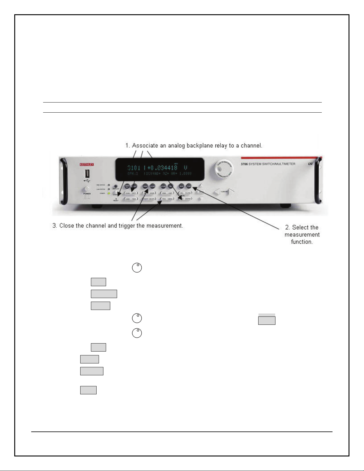
Example 2: Close a channel and take a measurement using the switch operation
method
In switch operation, backplane relays are not closed automatically. Backplane relays are closed only
when they are associated to a channel. When that channel is closed, the associated backplane relay also
closes. To take a measurement, the appropriate backplane relay must be associated with the channel to
route the signal to the DMM.
NOTE A backplane relay cannot be closed from the front panel as a stand-alone channel.
Figure 14: The switch operation method
1. Associate analog backplane relay channel 1921 and channel 1031:
c. Use the navigation wheel
to modify the channel designation from 001 to 031.
d. Press the EXIT key to return to the assigned channel display.
e. Press the CONFIG key. CONFIG+ is displayed.
f. Press the CHAN key.
g. Use the navigation wheel to select BACKPLANE > ADD, and then Enter.
h. Use the navigation wheel to modify the backplane relay channel from 1911 to 1921.
i. Press the EXIT key twice to return to the assigned channel display.
2. Press the FUNC key until 2WΩ is displayed.
3. Press the CLOSE key to close Channel 1031 and the associated analog backplane relay (Channel
1921).
4. Press the TRIG key to take a measurement.
5. Perform a factory reset (see Common task: Perform a factory reset for instructions).
3700S-903-01 Rev. C / November 2008 21
Page 28

Advanced applications
Perform a scan operation and save data to the USB drive
This example creates a ten-channel scan operation to measure voltage on ten sequential channels. A
buffer is created to store the scan data and save it to a standard USB flash drive (not included).
The example assumes a known voltage (or short) is connected across Channels 1 through 5 and 17
through 21 on a multiplexing switch module installed in Slot 1. See
Hardware and software requirements.
Figure 15: Create a scan list
Using the Quick Start Guide and
1. Create a scan list (see
Using the navigation wheel
a. Select and modify the start channel to 001.
b. Select and modify the end channel to 005.
c. Select
d. Press ENTER.
e. Press INSERT to add more channels to the scan list.
The front panel will display “Add to Scan….”
2. Repeat steps 1.a. through 1.e to add Channels 1017 through 1021 to the scan list.
dcvolts as the assigned measurement function.
Figure 15).
:
22 3700S-903-01 Rev. C / November 2008
Page 29

3. Create a buffer (see Figure 16):
a. Press the STORE key on the front panel.
b. Use the navigation wheel to select CREATE > fpbuf.
NOTE The default buffer name is fpbuf, but it can be modified using the navigation wheel
the edit mode. This example assumes the buffer name is fpbuf.
c. Press Enter until CAPACITY 000010 is displayed.
d. Press Enter. The fpbuf MENU is displayed.
e. Use the navigation wheel to choose SELECT > fpbuf, and then Enter.
f. Press the EXIT key to return to the active channel display.
Figure 16: Create a buffer to save readings on a USB flash drive
4. Run the scan (see Figure 17):
in
a. Press the SCAN key.
b. Use the navigation wheel to select BACKGROUND.
c. Press Enter.
Figure 17: Run the scan
3700S-903-01 Rev. C / November 2008 23
Page 30

5. Store the buffer on a USB flash drive (see Figure 18):
Figure 18: Store the buffer on a USB flash drive
a. Insert the USB flash drive (not included) into the front panel USB connector.
b. Press the STORE key to access the buffer menu.
c. Use the navigation wheel to select SAVE > USB (hint: SAVE is to the right of DELETE).
d. Use the navigation wheel
to select the default buffer name fpbuf and change it to a more
meaningful name for storage on the USB flash drive.
e. Push the navigation wheel
until the Buffer menu is displayed. The data file is now stored in
the root directory on the USB flash drive.
6. Perform a factory reset (see Common task: Perform a factory reset for instructions).
24 3700S-903-01 Rev. C / November 2008
Page 31

Using the Analog backplane connector to take
measurements without a switch module
The rear panel analog backplane connector (DB-15) is always connected to the DMM input.
Measurements can be performed without a switch module by using the analog backplane connection.
Use a standard DB-15 mating connector (not supplied) to connect to the analog backplane on the rear
panel as shown in
NOTE The switch module and analog backplane connector cannot be used at the same time, because
they are connected in parallel.
There is no relay that connects to the DB-15.
Figure 19: Analog backplane connector
Figure 19.
Figure 20: Take measurements without a scanner module
3700S-903-01 Rev. C / November 2008 25
Page 32

To take measurements:
1. Connect the resistor to the input terminals.
2. Configure the measurement by pressing the FUNC key until 2WΩ is displayed.
3. Press the AUTO key to enable the auto range feature. "Auto" is displayed in upper right corner.
4. Press the TRIG key to trigger a reading.
5. Perform a factory reset (see Common task: Perform a factory reset for instructions).
26 3700S-903-01 Rev. C / November 2008
Page 33

Appendix A: Static IP address LAN connection
A point-to-point LAN connection to set up a static IP address between the PC and the instrument enables
the use of the instrument's internal web page and TSP™ Express.
Use the instructions below to configure the instrument's IP address based on the present IP address of
the host PC. Whenever there is an existing IP address configured for the network interface card’s network
settings, the IP address for the Ethernet instruments should be configured so that they are compatible.
Record all network configurations before modifying any existing network configuration information on the
network interface card. Once the network configuration settings are updated, the older information is lost.
This may cause a problem reconnecting the PC to a corporate network if DHCP mode is disabled.
CAUTION Be sure to return all settings to their original configuration prior to reconnecting the PC to
a corporate network. Failure to do this could result in damage to the equipment and loss
of data. Contact your system administrator for more information.
Step 1: Identify and record the PC's existing IP configuration information
1. Open the command prompt to see the existing IP configuration information (see Figure A-1):
• In Windows 2000/XP
a. Click the Start button, and then select Run.
b. Type cmd in the Open field and click OK.
• In Windows Vista:
a. Click the Start button.
b. Select All Programs.
c. Select Accessories.
d. Select Command Prompt.
TM
:
3700S-903-01 Rev. C / November 2008 27
Page 34

Figure A-1: Computer configuration using the command prompt
2. At the command prompt, type ipconfig/all, and then click Enter.
a. If the information for the Ethernet adapter displays Media Disconnected then close the
command prompt and skip to
address
.
Step 2: Disable DHCP to use the computer's existing IP
b. When the information is displayed, record the DHCP mode, IP address, subnet mask, default
gateway, and DNS server information.
CAUTION The ipconfig/all command displays the configuration of all network connections. Be
sure to record the information for the proper network card.
3. Verify selected status: DHCP or Static IP
• To determine the next step, check the DHCP Enabled setting in the IP configuration screen or in the
settings recorded earlier:
a. If DHCP Enabled = Yes, proceed to Step 2: Disable DHCP to use the computer's
existing IP address.
b. If DHCP Enabled = No, proceed to Step 3: Configure the instrument’s LAN settings.
NOTE When DHCP Enabled = Yes, the IP address of the PC is assigned automatically upon power
up. However, if DHCP Enabled = No, the network will not recognize the PC if the original
settings are changed. If at any time you are unsure how to proceed, contact your system
administrator.
4. To exit the IP configuration screen, type exit at the command prompt, and then press ENTER.
28 3700S-903-01 Rev. C / November 2008
Page 35

Step 2: Disable DHCP to use the computer's existing IP address
NOTE Do not change the IP address without talking to your system administrator first. Entering an
incorrect IP address can prevent your PC from connecting to your corporate network.
1. Open the Internet Protocol (TCP/IP) Properties dialog box (see Figure A-2):
• In Windows 2000:
a. Click the Start button, select Settings, and then open the Control Panel.
b. Select Network and Dial-up Connections.
c. Right-click Local Area Connection, and then select Properties. The Local Area Connection
Properties dialog box is displayed.
d. Double-click Internet Protocol (TCP/IP) in the items list. The Internet Protocol
(TCP/IP) Properties dialog box is displayed.
• In Windows XP:
a. Click the Start button, and then open the Control Panel.
b. Select Network Connections.
c. Right-click Local Area Connection, and then select Properties. The Local Area Connection
Properties dialog box is displayed.
d. Double-click Internet Protocol (TCP/IP) in the items list. The Internet Protocol
(TCP/IP) Properties dialog box is displayed.
• In Windows Vista:
a. Click the Start button, and then open the Control Panel.
b. Select Network & Sharing Center.
c. In the list, click View Status next to Connection. The Wireless Network Connection Status
dialog box is displayed.
d. Click Properties. Windows displays a permissions message.
e. If you are logged in as administrator, click Continue. If you are not logged in as an
administrator, enter the administrator's password to continue.
f. The Network Connection Properties dialog box is displayed.
g. Double-click Internet Protocol Version 6 (TCP/IPv6) in the items list. The Internet Protocol
Version 6 (TCP/IPv6) Properties dialog box is displayed.
3700S-903-01 Rev. C / November 2008 29
Page 36

Figure A-2: Internet Protocol (TCP/IP) Properties dialog box
2. Select Use the following IP address. The option for Use the following DNS server addresses is
automatically selected.
3. Set the IP Address:
a. Are the IP address and subnet mask fields populated?
• Yes: If populated, record the address, subnet mask, default gateway, and DNS servers to
use in Step 3: Configure the instrument’s LAN settings.
• No: If blank, enter the IP address 192.168.0.3 in the IP address field and 255.255.255.0
in the subnet mask field. These will be used to configure the instrument’s LAN settings.
b. After recording or entering the IP address, click OK to close the Internet Protocol (TCP/IP)
Properties dialog box.
4. Close the Network Connections window.
Step 3: Configure the Instrument's LAN settings
To configure the Series 3700 using the front panel:
1. Press MENU to display the MAIN MENU. Use the navigation wheel to select LAN to display
the LAN MENU.
2. Change the IP address assignment method:
a. Select CONFIG > METHOD > MANUAL, then press MENU.
b. Press EXIT once to return to the LAN MENU.
30 3700S-903-01 Rev. C / November 2008
Page 37

c. Select APPLY_SETTINGS > YES, then press ENTER.
3. Enter the IP address using the LAN MENU:
a. Select CONFIG > IP-ADDRESS.
b. Refer to the recorded computer's IP address that you recorded in Step 2. A portion of the
computer's IP address will be used as a base for the instrument's unique ID. Only the last
three numbers (after the last decimal point) of the PC and instrument will be different. The
last three digits may be anything from 1 to 255 (for a subnet mask of 255.255.255.0).
For example, the Internet Protocol (TCP/IP) Properties dialog box shows that the computer's
IP address is 192.168.0.3. A unique address for the instrument is 192.168.001.101.
NOTE The instrument’s IP address can have leading zeros, but the computer’s IP address cannot.
c. Use the navigation wheel to select and enter an appropriate IP address for the instrument. Be
sure to record the instrument’s IP address to use in
web page
.
Step 5: Access the instrument's internal
d. Press ENTER or the navigation wheel to confirm the changes.
e. Press EXIT to return to the LAN MENU.
f. From the LAN MENU, select APPLY_SETTINGS > YES, and then press ENTER.
4. Change the subnet mask from within the LAN MENU:
a. Select CONFIG > SUBNETMASK, and then press ENTER. The SUBNET MASK menu item
is to the right of GATEWAY. Use the navigation wheel to scroll through the options.
b. Modify the SUBNETMASK to match the PC settings recorded earlier (or 255.255.255.000 if
DHCP Enabled = YES).
c. Press ENTER or the navigation wheel when you have finished changing all the
characters.
d. Press EXIT to return to the LAN MENU.
e. From the LAN MENU, select APPLY_SETTINGS > YES, and then press ENTER.
3700S-903-01 Rev. C / November 2008 31
Page 38

NOTE APPLY_SETTINGS must be used before changes to the IP address or subnet mask are
applied.
Step 4: Connect the crossover cable from the instrument to the PC network
interface card
Connect the supplied crossover cable between the computer's NIC card and the Ethernet connector on
the instrument’s rear panel. There are multiple connectors on the Series 3700 rear panel; be sure to
connect to the LAN connection port.
Connect the crossover cable into the same PC Ethernet port that was used during the configuration of the
instrument. This will ensure that the system is using the correct network card.
Step 5: Access the instrument's internal web page
1. Open a web browser on the host PC.
2. Enter the instrument’s IP address in the browser's address box. For example, if the instrument's IP
address is 192.168.0.3, enter 192.168.0.3 in the browser's address box.
3. Press ENTER on the PC keyboard to open the instrument’s web page.
NOTE If the web page does not open in the browser, see
Appendix C: Troubleshooting.
32 3700S-903-01 Rev. C / November 2008
Page 39

Appendix B: Assigning a static IP configuration from the embedded web interface
You can assign a static IP address to the Series 3700 using the embedded web interface or by using ICL
commands on any command interface (see the Series 3700 Reference Manual for more information
about ICL commands).
To assign a static IP address using the embedded web interface:
1. Perform the steps in Appendix A: Static IP address LAN connection to establish a connection with
the instrument. After completing Step 8, the embedded web interface of the Model 3706
mainframe (shown in
2. Navigate to the IP configuration page (see
menu on the left side of the embedded web interface screen. Click the Modify button. You will be
asked for a user name and password. Use the following:
Figure 9) appears in your browser window.
Figure B-1) by clicking IP Config under the LXI Page
Username: admin
Password: admin
Click the OK button to access and change the IP configuration.
Figure B-1: IP configuration page
3700S-903-01 Rev. C / November 2008 33
Page 40

3. Select Manual next to TCP/IP Configuration Mode.
4. On the Modify IP Configuration page (see Figure B-2), type in the desired Static IP address,
Default Gateway, and DNS Server information.
Figure B-2: Modify IP Configuration Page
5. Click Submit to apply the new settings. The instrument will reconfigure its settings, which may
take a few moments (see
Figure B-3).
NOTE You may lose your connection with the embedded web interface after clicking Submit; this is
normal and does not indicate an error or failure of the operation. If this occurs, simply reopen
the instrument's web page to continue.
Figure B-3: Reconfiguring settings
34 3700S-903-01 Rev. C / November 2008
Page 41

Appendix C: Troubleshooting
Table C-1: Using the LAN connection with the LXI Discovery tool
Problem Possible root causes Suggestions
Not able to connect to
web page.
LXI Browser network
instrument screen not
shown.
Still having problems? Contact Keithley Applications at 800-552-1115
• TCP/IP settings not set to
auto.
• Network card disabled.
• Multiple network cards
enabled in one PC with
both enabled and TCP/IP
settings are configured to
obtain IP addresses
automatically on more
than one NIC.
• Enable automatic TCP/IP address selection
Step 2: Configure the network interface
(see
card (NIC) of the PC to obtain an IP address
automatically.
• Enable network connections.
• Disable one network card or use the static
IP address method.
• Contact your system administrator for
additional assistance.
for more support.
)
Table C- 2: Front-panel errors
Problem Possible root causes Suggestions
Error “1114, settings
conflict error,” is returned.
Error: "1114, Settings
conflict with interlock
connection" displays.
Measurements returned
are not as expected.
Still having problems? Contact Keithley Applications at 800-552-1115
The channel that is being
closed has “nofunction”
assigned to it.
Some switching modules can
switch high-voltage signals.
For safety reasons, hardware
interlocks are provided on the
switching module. These
interlocks are designed to
keep the switching module
disconnected from the system
backplane. When the
interlock circuit is disengaged,
no measurements can be
performed through a
switching module; channel
relays can continue to
operate, however.
To use dmm.close, you must assign a valid
function to a channel during remote operation.
For front-panel operation, see
a channel and take a measurement using the
DMM operation method
• When the interlock connection is removed,
the analog backplane relays are disabled
and will be open.
• When using a screw terminal panel, the
interlock connection is closed and
backplane relays are engaged when the
screw terminal is connected.
• Satisfy interlock requirements on the switch
module (for requirement details, refer to
Section 9 in the Series 3700 User's
Manual).
for more support.
Example 1: Close
.
3700S-903-01 Rev. C / November 2008 35
Page 42

Table C- 3: Using the LAN connection with a static IP address
Problem Possible root causes Suggestions
Unable to connect to the
web page
• Entered zeros in the
web browser for
instrument IP address.
TM
Unable to open switch
card diagram page on
web page
• JAVA
Standard Edition 6 not
installed
Platform,
• Switch card not
installed
Instrument IP address is
000.000.000.000
• Instrument DHCP is
set to Auto
• Did not apply changes
to IP address
• Computer DHCP
mode is enabled
• Crossover cable is not
connected to the
proper port
Still having problems? Contact Keithley Applications at 800-552-1115
• Verify the instrument IP address is
compatible with the IP address on the
computer.
• Verify instrument IP address is appropriate;
from within the LAN menu; select
STATUS > IPADDRESS.
• See
Step 4: Connect the LAN crossover
cable from the instrument to the PC
• Review Network Tutorial for Ethernet
Instruments.
• Do not type any leading zeros.
TM
Install JAVA
Platform, Standard Edition 6. If
the computer is connected to the Internet, a
window should appear to prompt you to
automatically download and install the JRE. If
the computer is not connected to the Internet or
the window does not appear, JAVA
Standard Edition 6 can be downloaded from
www.java.com.
• See
Step 4: Connect the LAN crossover
cable from the instrument to the PC
• See Step 3: Configure the Instrument's LAN
settings
. Be sure to select
APPLY_SETTINGS > YES to apply your
changes
• See
• See
Appendix A: Static IP address LAN
connection
.
Step 4: Connect the LAN crossover
cable from the instrument to the PC.
for more support.
.
TM
Platform,
.
36 3700S-903-01 Rev. C / November 2008
Page 43

Page 44

12/06
Specifications are subject to change without notice.
All Keithley trademarks and trade names are the property of Keithley Instruments, Inc.
All other trademarks and trade names are the property of their respective companies.
A GREATER MEASURE OF CONFIDENCE
Keithley Instruments, Inc.
Corporate Headquarters • 28775 Aurora Road • Cleveland, Ohio 44139 • 440-248-0400 • Fax: 440-248-6168 • 1-888-KEITHLEY • www.keithley.com
 Loading...