

Page 1

Series 2600-PCT-xB
Parametric Curve Tracer
User’s Manual
-900-01 Rev. B August 2022
PCT
tek.com/keithley
*PPCT-900-01B*
PCT-900-01B
Page 2

Parametric Curve Tracer
Series 2600-PCT-xB
User's Manual
Page 3

© 2022, Keithley Instruments, LLC
Cleveland, Ohio, U.S.A.
All rights reserved.
Any unauthorized reproduction, photocopy, or use of the information herein, in whole or in part,
without the prior written approval of Keithley Instruments, LLC, is strictly prohibited.
These are the original instructions in Engli sh.
All Keithley Instruments product names are trademarks or registered trademarks of Keithley
Instruments, LLC. Other brand names are trademarks or registered trademarks of their respective
holders.
Microsoft, Visual C++, Excel, and Windows are either registered trademarks or trademarks of
Microsoft Corporation in the United States and/or other countries.
Document number: PCT-900-01 Rev. B August 2022
Page 4

Safety precaut ions
The following safety precautio ns should be observed before using this product and any associated ins tr ument a tion . Alt ho ugh
some instruments and accessories would normally be used with nonhazardous voltages, there are situations where hazardous
conditions may be present.
This product is intended for use by personnel who recognize shock hazards and are familiar with the safety precautions required
to avoid possible injury. Read and follow all installation, operation, and maintenance information careful ly before using the
product. Refer to the user documentation for complete product specifications.
If the product is used in a manner not specified, the protection provided by the product warranty may be impaired.
The types of product users are:
Responsible body is the individual or group responsible for the use and maintenance of equipment, for ensuring that the
equipment is operated within its specifications and operating limits, and for ensuring that operators are adequately trained.
Operators use the product for its intended function. They must be trained in electrical safety procedures and proper use of the
instrument. They must be protected from electric shock and contact with hazardous live circuits.
Maintenance personnel perform routine procedures on the product to keep it operating properly, for example, setting the line
voltage or replacing consumable materials. Maintenance procedures are described in the user documentation. The procedures
explicitly state if the operator may perform them. Otherwise, they should be performed only by service personnel.
Service personnel are trained to work on live circuits, perform safe installations, and repair products. Only properly trained
service personnel may perform insta llat ion and service procedures.
Keithley products are designed for use with electrical signals that are measurement, control, and data I/O connections, with low
transient overvoltages, and must not be directly connected to mains voltage or to voltage sources with high transient
overvoltages. Measurement Category II (as referenced in IEC 60664) connections require protection for high transient
overvoltages often associated with local AC mains connections. Certain Keithley measuring instruments may be connected to
mains. These instruments will be marked as category II or higher.
Unless explicitly allowed in the specifications, operating manual, and instrument labels, do not connect any instrument to mains.
Exercise extreme caution when a shock hazard is present. Lethal voltage may be present on cable connector jacks or test
fixtures. The American National Standards Institute (ANSI) states that a shock hazard exists when voltage levels greater than
30 V RMS, 42.4 V peak, or 60 VDC are present. A good safety practice is to expect that hazardous voltage is present in any
unknown circuit before measuring.
Operators of this product must be protected from electric shock at all times. The responsible body must ensure that operators
are prevented access and/or insulated from every connection point. In some cases, connections must be exposed to potential
human contact. Product operators in these circumstances must be trained to protect themselves from the risk of electric shock. If
the circuit is capable of operating at or above 1000 V, no conductive part of the circuit may be exposed.
Do not connect switching cards directly to unlimited power circuits. They are intended to be used with impedance-limited
sources. NEVER connect switching cards directly to AC mains. When connecting sources to switching cards, install protective
devices to limit fault current and voltage to the card.
Before operating an instrument, ensure that the line cord is connected to a properly-grounded power receptacle. Inspect the
connecting cables, test leads, and jumpers for possible wear, cracks, or breaks before each use.
When installing equipment where access to the main power cord is restricted, such as rack mounting, a separate main input
power disconnect device must be provided in close proximity to the equipment and within easy reach of the oper ator.
For maximum safety, do not touch the product, test cables, or any other instruments while power is applied to the circuit under
test. ALWAYS remove power from the entire test system and discharge any capacitors before connecting or disconnecting
cables or jumpers, installing or removing switching cards, or making internal changes, such as installing or removing jumpers.
Do not touch any object that could provide a current path to the common side of the circuit under test or power line (earth)
ground. Always make measurements with dry hands while standing on a dry, insulated surface capable of withstanding the
voltage being measured.
Page 5

For safety, instruments and accessories must be used in accordance with the operating instructions. If the instruments or
accessories are used in a manner not specified in the operating instructions, the protection provided by the equipment may be
impaired.
Do not exceed the maximum signal levels of the instruments and accessories. Maximum signal levels are defined in the
specifications and operating information and shown on the instrument panels, test fixture panels, and switching cards.
When fuses are used in a product, replace with the same type and rating for continued protection again st fire haz ar d.
Chassis connections must only be used as shield connections for measuring circuits, NOT as protective earth (safety ground)
connections.
If you are using a test fixture, keep the lid closed while power is applied to the device under test. Safe operation requires the use
of a lid interlock.
If a screw is present, connect it to protective earth (safety ground) using the wire recommended in the user documentation.
The symbol on an instrument means caution, risk of hazard. The user must refer to the operating instructions located in the
user documentation in all cases where the symbol is mark ed on the instr u ment .
The symbol on an instrument means warning, risk of electric shock. Use standard safety precautions to avoid personal
contact with these voltages.
The symbol on an instrument shows that the surface may be hot. Avoid personal contact to prevent burns.
The symbol indicates a connection terminal to the equipment frame.
If this symbol is on a product, it indicates that mercury is present in the display lamp. Please note that the lamp must be
properly disposed of according to federal, state, and local laws.
The WARNING heading in the user documentation explains hazards that might result in personal injury or death. Always read
the associated information very carefully before performing the indicated procedure.
The CAUTION heading in the user documentation explains h azard s that coul d dama ge the instrument. Such damage may
invalidate the warranty.
The CAUTION heading with the symbol in the user documentation explains hazards that could result in moderate or minor
injury or damage the instrument. Always read the associated information very carefully before performing the indicated
procedure. Damage to the instrument may invalidate the warranty.
Instrumentation and accessories shall not be connected to humans.
Before performing any maintenance, disconnect the line cord and all test cables.
To maintain protection from electric shock and fire, replacement components in mains circuits — including the power
transformer, test leads, and input jacks — must be purchased from Keithley. Standard fuses with applicable national safety
approvals may be used if the rating and type are the same. The detachable mains power cord provided with the instrument may
only be replaced with a similarly rated power cord. Other components that are not safety-related may be purcha sed fr om ot her
suppliers as long as they are equivalent to the original component (note that selected parts should be purchased only through
Keithley to maintain accuracy and functionality of the product). If you are unsure about the applicability of a replacement
component, call a Keithley office for information.
Unless otherwise noted in product-specific literature, Keithley instruments are designed to operate indoors only, in the following
environment: Altitude at or below 2,000 m (6,562 ft); temperature 0 °C to 50 °C (32 °F to 122 °F); and pollution degree 1 or 2.
To clean an instrument, use a cloth dampened with deionized water or mild, water-based cleaner. Clean the exterior of the
instrument only. Do not apply cleaner directly to the instrument or allow liquids to enter or spill on the instrument. Products that
consist of a circuit board with no case or chassis (e.g., a data acquisition board for installation into a computer) should never
require cleaning if handled according to instructions. If the board becomes contaminated and operation is affected, the board
should be returned to the factory for proper cleaning/servicing.
Safety precaution revision as of June 2018.
Page 6

Table of contents
Introduction ............................................................................................................... 1-1
Welcome .............................................................................................................................. 1-1
Introduction to this manual ................................................................................................... 1-1
Available configurations ....................................................................................................... 1-2
Extended warranty ............................................................................................................... 1-2
Contact information .............................................................................................................. 1-2
Instruments and connections .................................................................................. 2-1
Introduction .......................................................................................................................... 2-1
Unpacking the PCT .............................................................................................................. 2-1
About the Model 8010 High Power Device Test Fixture ...................................................... 2-2
About the Model 8020 High Power Interface Panel ............................................................. 2-3
Connections to protective earth (safety ground) .................................................................. 2-3
Interlock connections ........................................................................................................... 2-4
Connect instruments to the Model 8010 .............................................................................. 2-5
Connect instruments to the Model 8020 .............................................................................. 2-6
Getting started with ACS Basic ............................................................................... 3-1
Introduction .......................................................................................................................... 3-1
Installing and configuring the GPIB interface ....................................................................... 3-1
TSP-Link system setup ........................................................................................................ 3-2
Assign TSP-Link node numbers ................................................................................................ 3-2
Connect the instrument for communications ............................................................................. 3-3
Software installation ............................................................................................................. 3-4
Verify hardware configuration .............................................................................................. 3-5
Start ACS Basic ................................................................................................................... 3-9
ACS Basic test modes ....................................................................................................... 3-10
I-V applications for power MOSFETs ....................................................................... 4-1
Section overview and equipment requirements ................................................................... 4-1
On-state characteristics ....................................................................................................... 4-1
Configure the test fixture ........................................................................................................... 4-1
Collecting I-V curves in TraceMode .......................................................................................... 4-4
Configure a fixed plot .............................................................................................................. 4-11
Collecting I-V curves in MultiM ode .......................................................................................... 4-13
Digitizing pulses and improving timing .................................................................................... 4-26
Off-state characteristics ..................................................................................................... 4-34
Configure the test fixture ......................................................................................................... 4-34
Measuring leakage current in MultiMo de ................................................................................ 4-37
Page 7

Table of contents
s Manual
Series 2600-PCT-xB Parametric Curve Tracer User'
C-V applications on power MOSFETs ..................................................................... 5-1
Overview and requirements ................................................................................................. 5-1
Background of MOSFET capacitance measurements ......................................................... 5-1
Safety precautions and discharge procedures .................................................................... 5-4
Discharging bias tee capacitance in the Model 8010 ................................................................ 5-4
Discharging bias tee capacitance within the Model 8020 .......................................................... 5-8
Discharge system capacitance from SMU front panel interface .............................................. 5-10
Model 8010 connections .................................................................................................... 5-10
Model 8010 Crss test connections .......................................................................................... 5-10
Model 8010 Ciss test connections ........................................................................................... 5-12
Model 8010 Coss test connections ......................................................................................... 5-13
Model 8010 connections to the device for Crss....................................................................... 5-14
Model 8010 connections to the device for Ciss and Coss ....................................................... 5-15
Model 8020 connections .................................................................................................... 5-15
Model 8020 Crss test connections .......................................................................................... 5-16
Model 8020 Ciss test connections ........................................................................................... 5-17
Model 8020 Coss connections ................................................................................................ 5-18
Model 8020 test connections to the device ............................................................................. 5-19
Perform connection compensations on C-V measurements ............................................. 5-20
Ciss compensatio n .................................................................................................................. 5-20
Coss compensation ................................................................................................................. 5-27
Crss compensation ................................................................................................................. 5-32
Make a Ciss measurement ................................................................................................ 5-38
Make a Coss measurement ............................................................................................... 5-46
Make a Crss measurement ................................................................................................ 5-57
Optimizing Crss measurement connections for difficult measure ments ............................ 5-64
Troubleshooting FAQs ............................................................................................. 6-1
Missing cables ...................................................................................................................... 6-1
2600-PCT-1B and C-V measurements ................................................................................ 6-1
2600-PCT-2B and C-V measurements ................................................................................ 6-1
Custom tests in ACS Basic .................................................................................................. 6-2
Page 8

Contact information ...................................................................1-2
In this section:
Welcome
The Keithley Instrument Parametric Curve Tracer provides configurations that are complete solutions
configured with a variety of high quality instruments, cables, and test fixtures. This building block
approach offers the advantages of easy upgrade or modifications to meet changing test needs. For
example, a low cost 200 V at 10 A system can be purchased initially, and 50 A or 100 A capability
can be added later. Additionally, you can use these instruments and accessories with different test
system platforms, such as for reliability or device qualification testing.
Section 1
Introduction
Welcome ...................................................................................1-1
Introduction to this manual ........................................................1-1
Available configurations ............................................................1-2
Extended warranty ....................................................................1-2
Parametric Curve Trace configurations include everything you need to quickly develop a complete
test system.
The ACS Basic Edition software provides complete device characterization, including both real-time
trace mode for quickly checking fundamental device parameters like breakdown voltage and full
parametric mode for extracting precise device parameters. ACS Basic Edition goes beyond traditional
curve tracer interfaces by offering a broad array of sample device libraries. You have complete
control of all test resources, allowing you to create more advanced tests than previously possible on a
curve tracer.
Introduction to this manual
This manual describes how to set up and use the Parametric Curve Tracer and ACS Basic software,
including:
• Assembling the PCT
• Getting started with ACS Basic
• Performing tests with the software, using both TraceMode and Parametric Test mode
This manual provides detailed applications to help you achieve success with your Keithley
Instruments PCT.
Page 9

Section
User's Manual
2600-PCT-1B
200 V / 10 A
200 V / 10 A
200 V / 10 A
N/A
2600-PCT-2B
200 V / 10 A
40 V / 50 A
200 V / 10 A
200 V / 10 A
2600-PCT-3B
3 kV / 120 mA
200 V / 10 A
200 V / 10 A
200 V / 10 A
2600-PCT-4B
3 kV / 120 mA
40 V / 50 A
200 V / 10 A
200 V / 10 A
1: Introduction Series 2600-PCT-xB Parametric Curve Tracer
Each application is presented with an overview of the application, followed by instructions to complete
the application.
For more detailed information on specific system components, refer to the documentation. For
instruments, the documentation is available at tek.com/keithley
available from the Help menu.
Available configurations
. For ACS Basic, documentation is
Model Collector / Drain Supply Step Generator
Low power
High current
High voltage
High current
and high
voltage
The Keithley Instruments Model 2651A may be added to increase the high current mode to either 50
A or 100 A. Other available accessories include the PCT-CVU Multi-Frequency Capacitance-Voltage
(C-V) Meter, the Model 8010 High Power Device Test Fixture, the Model 8020 High Power Interface
Panel, and the CVU-200-KIT and CVU-3K-KIT bias tee kits.
Extended warrant y
Additional years of warranty coverage are available on many products. These valuable contracts
protect you from unbudgeted service expenses and provide additional years of protection at a fraction
of the price of a repair. Extended warranties are available on new and existing products. Contact your
local Keithley Instruments office, sales partner, or distributor for details.
High Voltage
Mode
High Current
Mode
Base / Gate Supply
Auxiliary
Supply
Contact information
If you have any questions after you review the information in this documentation, please contact your
local Keithley Instruments office, sales partner, or distributor. You can also call the Tektronix
corporate headquarters (toll-free inside the U.S. and Canada only) at 1-800-833-9200. For worldwide
contact numbers, visit tek.com/en/contact-tek
1-2 PCT-900-01 Rev. B August 2022
.
Page 10

Connect instruments to the Model 8020 ...................................2-6
In this section:
Introduction ...............................................................................2-1
Unpacking the PCT ...................................................................2-1
About the Model 8010 High Power Device Test Fixture ............2-2
About the Model 8020 High Power Interface Panel ..................2-3
Connections to protective earth (safety ground) .......................2-3
Interlock connections ................................................................2-4
Connect instruments to the Model 8010 ...................................2-5
Introduction
Section 2
Instruments and connections
You must connect the instruments to either the Model 8010 High Power Device Test Fixture or the
Model 8020 High Power Interface Panel and then set up the TSP-Link network. The cables supplied
with your PCT can be used with either fixture. This describes how to make these connections.
If you choose to install the instruments in a rack, install the instruments in the rack before connecting
the instruments to the test fixture or interface panel. Please refer to the instructions in the rack mount
kits for more information.
Unpacking the PCT
The PCT shipping container contains a box labeled “Open Me First” that contains all the instrument
accessories and user documentation. In this box, the accessories for each instrument in your
configuration are enclosed in individual boxes and bags. Each box includes a document describing
the contents of the box.
On the same shipping pallet are each SMU of your PCT configuration and any other larger PCT
accessories, such as a Model 8010 High Power Device Test Fixture, a Model 8020 High Power
Interface Panel, the PCT-CVU instrument option, or the optional 200 V or 3 KV bias tee kits.
The PCT is generally connected to either a Model 8010 or a Model 8020. The following section
provides overview for these devices.
Page 11

Section
User's Manual
2: Instruments and connections Series 2600-PCT-xB Parametric Curve Tracer
About the Model 8010 Hi gh Power Device Test Fixture
The Model 8010 High-Power Device Test Fixture provides a safe, low noise, complete environment
for testing a variety of packaged device types. The replaceable socket module test boards allow for a
variety of package types, in cluding the user-supplied socket types.
The Model 8010 allows you to connect one Model 2657A High Power SourceMeter for up to 3 KV
testing. You can use one or two Model 2651A High Power SourceMeters for 15 A dc testing or 50 A
or 100 A pulse testing. For lower power terminals, you can connect up to two other SourceMeters,
such as Models 2611B, 2612B, 2635B, 2636B, 4200-SMU, or 4210-SMU.
The Model 8010 includes :
• Kelvin (remote sense) connections for five instruments
• Guarded pathways for picoampere level measurements even at 3 kV
• An access port for a variety of probes, such as scope or temperature
• Integrated protection circuits to protect Models 2611B, 2612B, 2635B, 2636B, 4200-SMU, and
4210-SMU from high voltage instruments
• Two independent test sockets, one for high current and one for high voltage
The test fixture is fully interlocked, providing safe operation for up to six different instruments. It is
declared safe through CE marking and certified through nationally recognized testing laboratories.
The Model 8010 is shipped with two 8010-DTB high power socket module test boards installed. The
boards include sockets for TO-247 and axial lead devices.
The high current side of the test fixture can be used with up to 100 amps pulsed, 15 amps dc,
200 V dc. Up to four measurement resources can be connected (two high current, two low power).
The high voltage side of the test fixture can be used with up to 3030 V dc at 120 mA, 200 V dc up to
10 A pulsed. Connections are provided for up to three measurement resources (one high voltage, two
low power).
For information on the Model 8010, including fixture setup within a test system, see the Model 8010
High Power Device Test Fixture User's Manual, available at tek.com/keithley
.
2-2 PCT-900-01 Rev. B August 2022
Page 12

Series 2600
Instruments and connections
-PCT-xB Parametric Curve Tracer User's Manual Section 2:
About the Model 8020 High Power In t er f ace Panel
The Model 8020 has six measurement pathways accommodating 3 kV, 200 V, and 100 A
measurements. You can configure five of the pathways with a variety of output connector types to
match your probe station. You can configure four pathways with the optional bias tees. This provides
high voltage C-V measurements on up to 4 pins of the device under test.
The Model 8020 comes with a selection of resistors that you can install to provide stability and extra
protection to the device.
Additionally, the Model 8020 offers the following:
• A common LO reference
• Overvoltage protection for all 200 V channels, ideal for device testing configurations using 200 V
SMUs and higher voltage SMUs
• A variety of connector types
• A single interlock interface for multiple instruments
• An interface for adding series resistor elements for measurement stability and absolute current
limit
• Optional transient overcurrent protection on the 200 V channels
• Expansion ports to easily link multiple 8020 interface panels
The Model 8020 can be configured to suit your probe station and test system. Contact your Keithley
Instruments applications engineer or see the Model 8020 High Power Interface Panel User's Manual,
available at tek.com/keithley
.
Connections to protective earth (safety ground)
The ground wires must be attached to a known protecti ve earth (safety ground) before
powering on instruments. Failure to attach the ground wires to a known protective earth may
result in electric shock.
Connections to protective earth (safety ground) are made at terminals labeled with the
following symbol.
Figure 1: Protective earth (safety ground) symbol
For detailed Model 8010 and Model 8020 instrument connection diagrams, including safety ground
details, see Connect instruments to the Model 8010 (on page 2-5) or
Model 8020 (on page 2-6).
PCT-900-01 Rev. B August 2022 2-3
Connect instruments to the
Page 13

Section
User's Manual
2: Instruments and connections Series 2600-PCT-xB Parametric Curve Tracer
Interlock connections
For proper interlock functionality, any instruments connected to the interlock must be powered on or
disconnected from the interlock.
Each Parametric Curve Tracer configuration contains instruments that can output hazardous live
voltages. To ensure operator safety, it is important to use the instrument interlock properly with the
Model 8010 and Model 8020 test fixtures. Both the Model 8010 and Model 8020 include interlock
connectors to interface with Series 2600B, Series 2650A, and 4200A-SCS instruments. Refer to the
instrument connection diagrams later in this section for illustrations on how to connect to the
individual SMU instruments.
With the Model 8010, the interlock switch is engaged when the lid is closed and latched. When the
interlock switch is engaged, a light on the enclosure is illuminated. You can turn on a SMU output
only when the interlock switch is engaged. If the lid is open, the interlock switch will not engage and
any SMUs with outputs that are configured for high voltage will not turn on.
For the Model 8020, the Interlock OUT connector on its device connections panel side of the panel is
designed for use with the supplied 8020-ILC-UNT interlock to unterminated cable. The interlock
enables the high-voltage outputs of the connected instruments when the normally-open switch at the
device under test (DUT) access point is closed.
The Model 8020 interlock is satisfied only when:
• The top cover to the 8020 is correctly installed and any top covers to other Model 8020s in the
test configuration are also correctly installed
• The system interlock is engaged (all normally-open switches are closed at DUT access points of
the test configuration)
When the 8020 interlock is satisfied, lights on the instrument connection and device connection
panels of the 8020 are illuminated.
For detailed information on the interlock requirements for the Model 8010 or Model 8020, see the
user's manual for that test fixture. For detailed information on the interlock requirements for a specific
SMU, see the reference manual for that SMU.
There is no safety interlock on the Model 2651A because its output voltage is below hazardous
evels. To activate Output Enable on the 2651A, refer to the Model 2651A Reference Manual. Output
l
Enable can be activated using the front panel or by remote control.
2-4 PCT-900-01 Rev. B August 2022
Page 14
Series 2600
Instruments and connections
-PCT-xB Parametric Curve Tracer User's Manual Section 2:
Connect instruments to the Model 8010
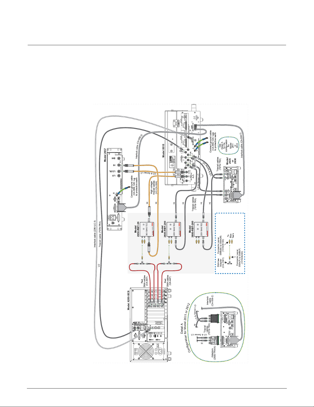
The following figure shows connections for I-V and C-V measurements. To make only connections for
I-V measurements, refer to the Model 8010 High Power Device Test Fixture User's Manual.
Figure 2: Instrument connections to the Model 8010
PCT-900-01 Rev. B August 2022 2-5
Page 15
Section
User's Manual
2: Instruments and connections Series 2600-PCT-xB Parametric Curve Tracer
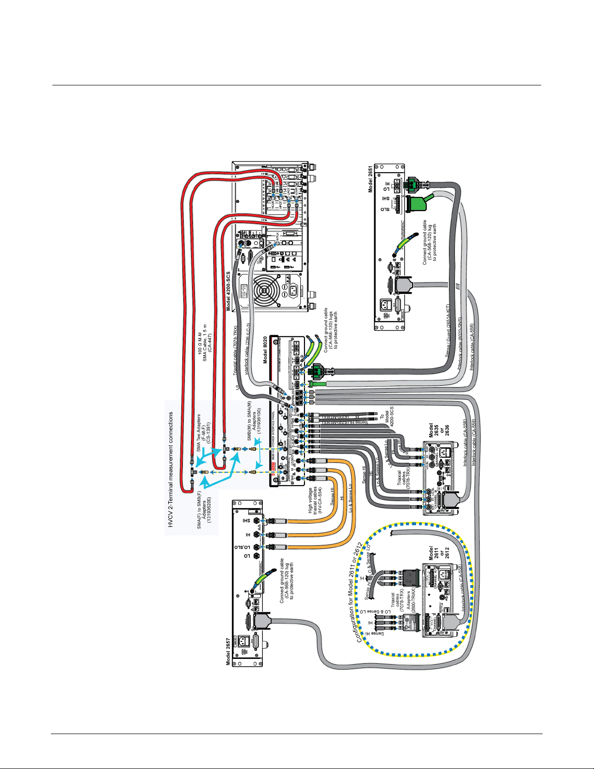
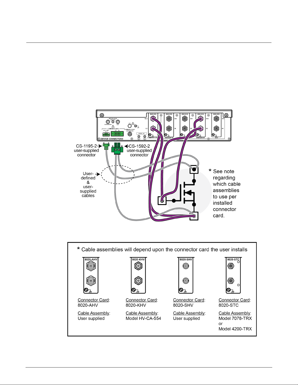
Connect instruments to the Model 8020
Figure 3: Connecting instruments to the Model 8020
2-6 PCT-900-01 Rev. B August 2022
Page 16

ACS Basic test modes ............................................................3-10
In this section:
Introduction ...............................................................................3-1
Installing and configuring the GPIB interface ............................3-1
TSP-Link system setup .............................................................3-2
Software installation ..................................................................3-4
Verify hardware configuration ...................................................3-5
Start ACS Basic ........................................................................3-9
Introduction
Section 3
Getting started with ACS Basic
ACS Basic Edition software is optimized for parametric testing of component and discrete (packaged)
semiconductor devices. ACS Basic supports all Keithley source and measure instrument products,
including Series 2600B, Series 2400, and Model 2651A and 2657A SourceMeter Instruments, and
Model 4200A-SCS Parameter Analyzers.
ACS Basic has a large device test library to allow you to get a test up and running quickly.
This section outlines how to configure the instruments in the PCT to prepare for connection to ACS
Basic, how to install the software, and how to get started using the software.
Installing and configuring the GPIB interface
If you ordered the PCT-CVU for high-voltage capacitance measurements, a GPIB interface is
installed on the Model 4200A-SCS that is included with the PCT-CVU. There is no need to use a
separate computer or install the KUSB-488B. Go to TSP-Link system setup (on page 3-2).
Page 17

Section
User's Manual
3: Getting started with ACS Basic Series 2600-PCT-xB Parametric Curve Tracer
ACS Basic software works with the following GPIB interfaces:
• KUSB-488
• KUSB-488A
• KUSB-488B
• KPCI-488
• KPCI-488A
• KPCI-488LP
• KPCI-488LPA
• NI USB-488
• NI PCI-488
If one of the above interfaces is already installed on your computer, please continue to
system setup (on page 3-2).
The PCT is supplied with Keithley’s Model KUSB-488B GPIB interface. If you are using a separate
computer for software control, install the GPIB interface if there is not one already installed. Refer to
the KUSB-488B documentation for instructions on installing the interface software.
TSP-Link system setup
ACS Basic automatically assigns the SMU identification numbers based on the TSP-Link setup. The
numbers differ based on your PCT configuration.
Assign TSP-Link node numbers
Each instrument in the TSP-Link network must have a unique TSP-Link node number. In addition,
ACS Basic requires that you set the master node to TSP-Link node number 1 and that each node that
is connected to the master has an incremental node number. For example, if you have a TSP-Link
network with three nodes, you must assign the instruments to the nodes 1, 2 and 3. Do not skip
numbers.
In PCT configurations, use the Model 2636B as the master node, assigned to node 1.
TSP-Link
If the PCT includes a Model 2657A , assign the 2657A to node 2.
The Model 2651A in a PCT-2B configuration should be assigned to node 2. If you have a second
2651A, assign it to the subsequent node.
The Model 2651A in a PCT-3B or -4B configuration should be assigned to node 3.
While other node configurations are possible, these assignments allow for simpler use of the
default ACS Basic tests.
3-2 PCT-900-01 Rev. B August 2022
Page 18

Series 2600
started with ACS Basic
-PCT-xB Parametric Curve Tracer User's Manual Section 3: Getting
To assign a node number from the front panel of the instrument:
1. Press the MENU key.
2. Select TSPLINK > NODE.
3. Press the navigation wheel and select the node number.
4. Press the ENTER key to save the node number.
Connect the instrument for communications
All configurations require a KUSB-488B or similar GPIB adapter cable connecting the instrument and
your computer. For additional connections, see the following details for your PCT configuration.
The 2600-PCT-1B configuration is shipped with the Model 2636B. The KUSB-488B or similar GPIB
adapter cable linking the Model 2636B and your computer is the only connection.
The 2600-PCT-2B configuration is shipped with the Models 2636B and 2651A. For this configuration,
connect the TSP-Link port of the Model 2636B to the TSP-Link port of the Mod el 2651A.
The 2600-PCT-3B configuration is shipped with the Models 2636B and 2657B. For this configuration,
connect the TSP-Link port of the Model 2636B to the TSP-Link port of the Model 2657A.
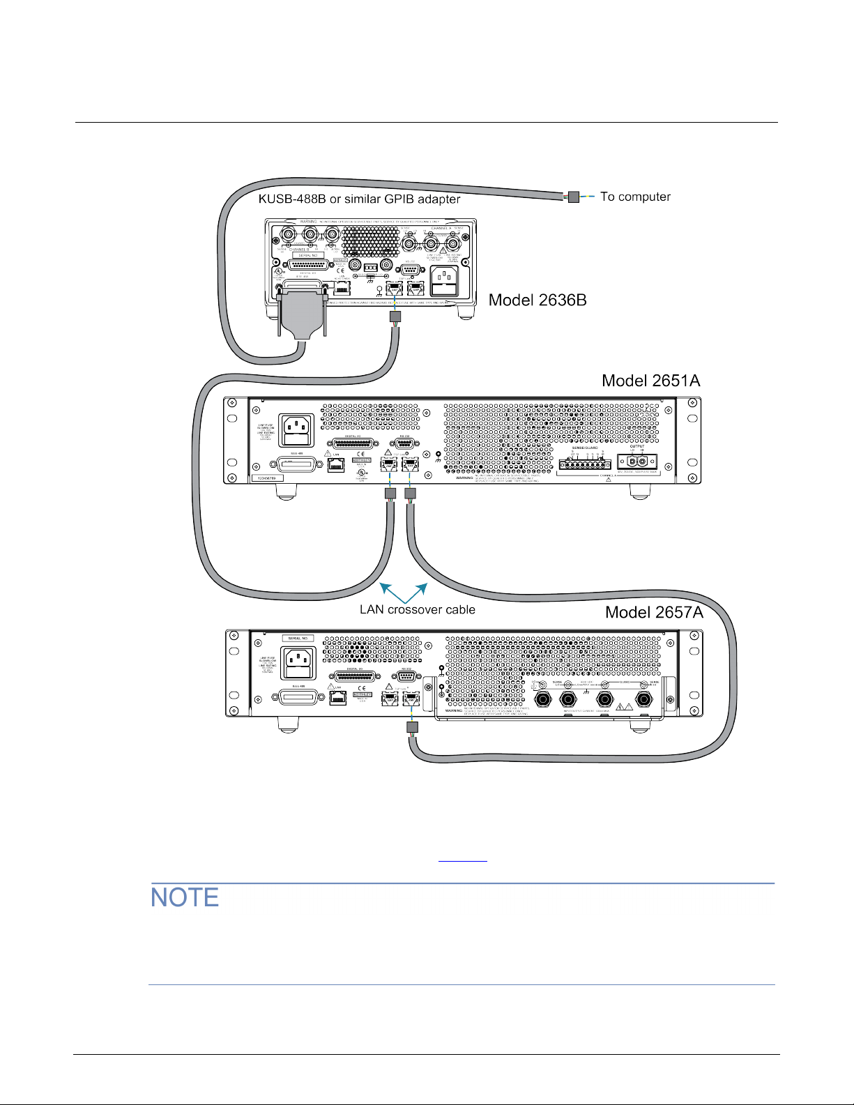
The following figure shows a 2600-PCT-4B configuration. The -4B configuration is shipped with the
Models 2636B, 2651A, and 2657B.
5. Press the EXIT key as needed to return to the main display.
PCT-900-01 Rev. B August 2022 3-3
Page 19
Section
User's Manual
3: Getting started with ACS Basic Series 2600-PCT-xB Parametric Curve Tracer
Figure 4: Communications connections
Software installation
See the ACS Basic release notes, availab le at tek.com, for instructions on installing the software.
It is recommended that you review the ACS Basic release notes. The release notes contain valuable
information about known issues and provide guidance on how to handle issues that you
may encounter.
3-4 PCT-900-01 Rev. B August 2022
Page 20
Series 2600
Getting started with ACS Basic
-PCT-xB Parametric Curve Tracer User's Manual Section 3:
Verify hardware configuration
Before starting ACS Basic, you need to set up the hardware for your test configuration.
ASC Basic checks for hardware changes when it starts up. You need to run ACS Hardware
gement whenever the hardware is changed.
Mana
To manage the hardware:
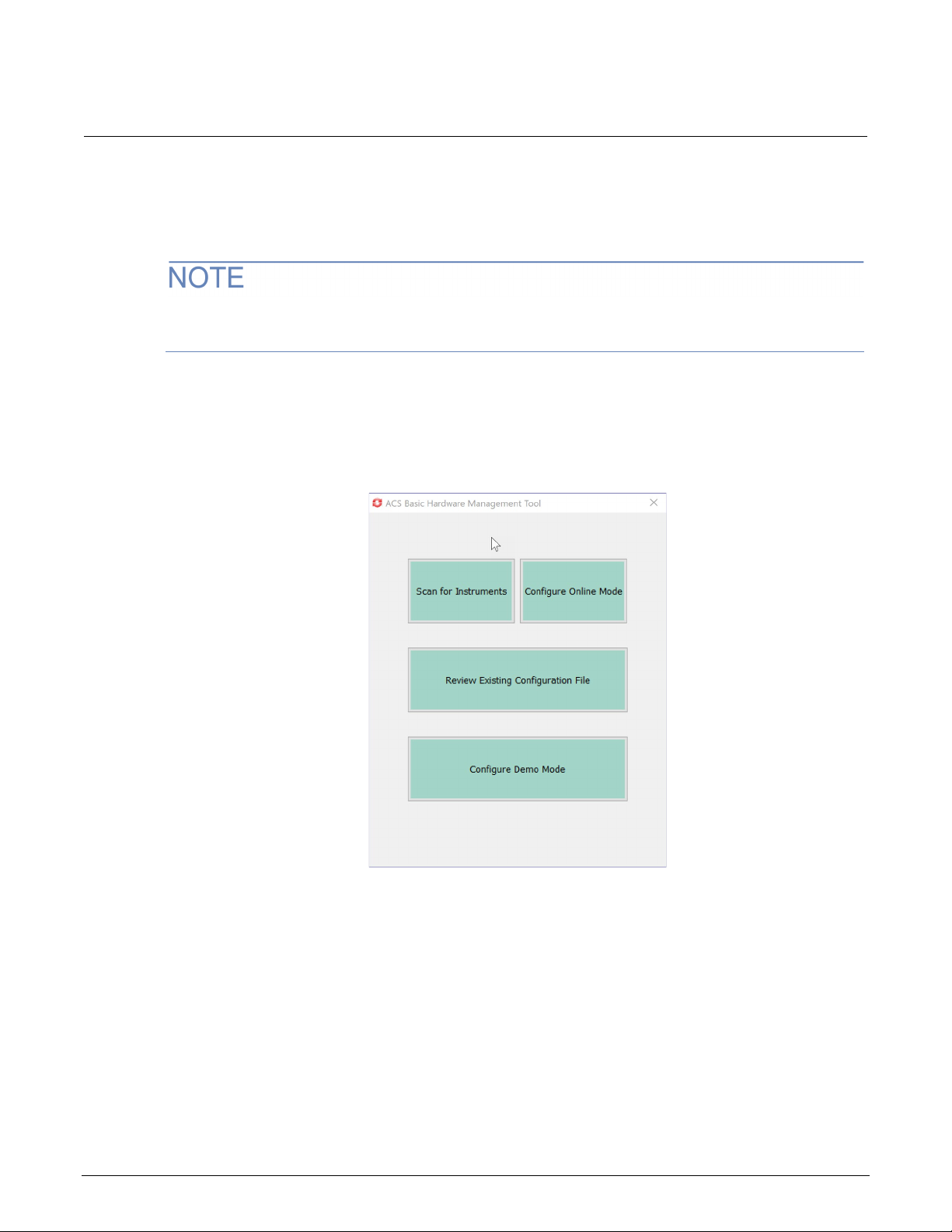
1. From Start, select Keithley ACS Basic HardwareManagement. The dialog shown in the
following figure is displayed.
Figure 5: Hardware Management Tool options
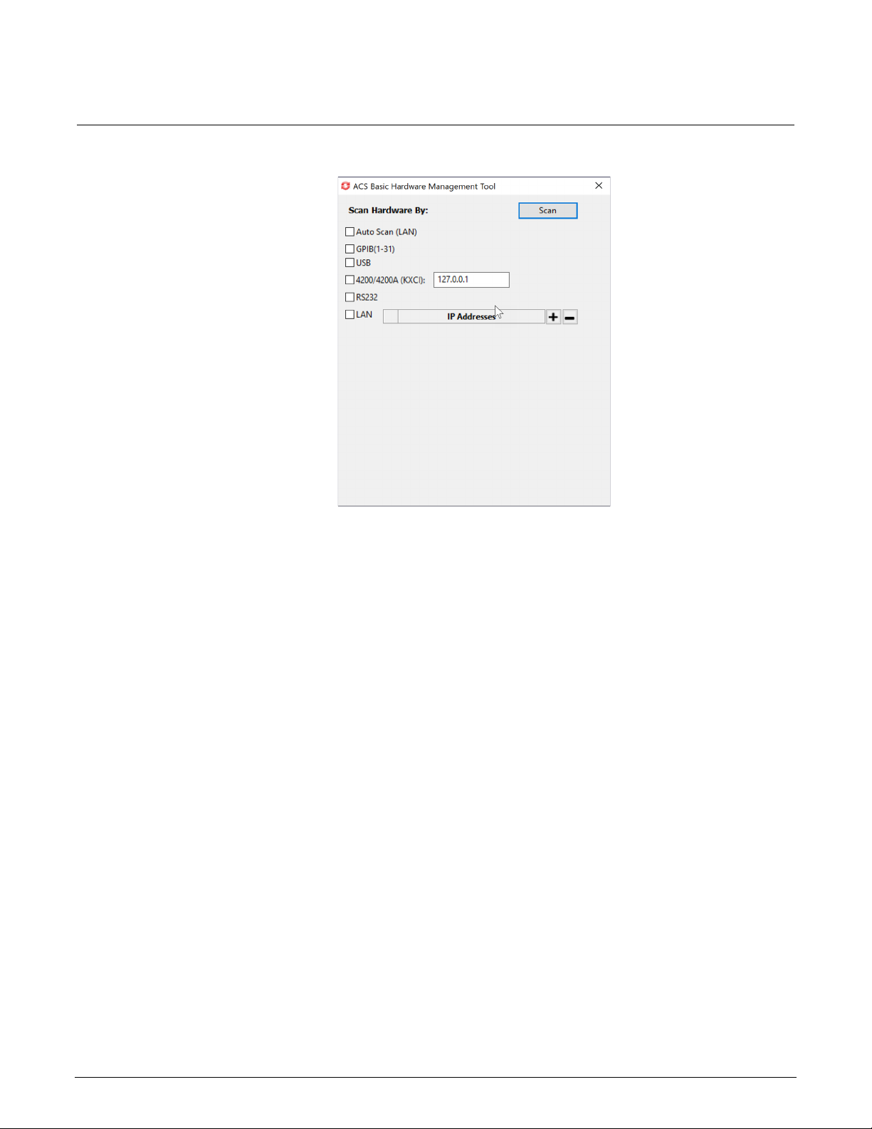
2. Select Scan for Instruments. The Scan Hardware By dialog is displayed, as shown in the
following figure.
PCT-900-01 Rev. B August 2022 3-5
Page 21
Section
User's Manual
3: Getting started with ACS Basic Series 2600-PCT-xB Parametric Curve Tracer
Figure 6: Scan Hardware By dialog
3. Select the options for your test. You can choose:
Auto Scan (LAN): Instruments are on the same subnet as the system computer (the first
three fields of the IP address are the same).
GPIB: Instrument addresses from 1 to 30 are supported.
Prober GPIB Address: Default value is 31.
USB
4200/4200A (KXCI): E nter the IP address in the text box.
RS-232
LAN: Use IP Addresse s to add or remove an IP address. To add an IP address, select + to
add a field. Enter the IP address. To remove an IP address, select the address and select –.
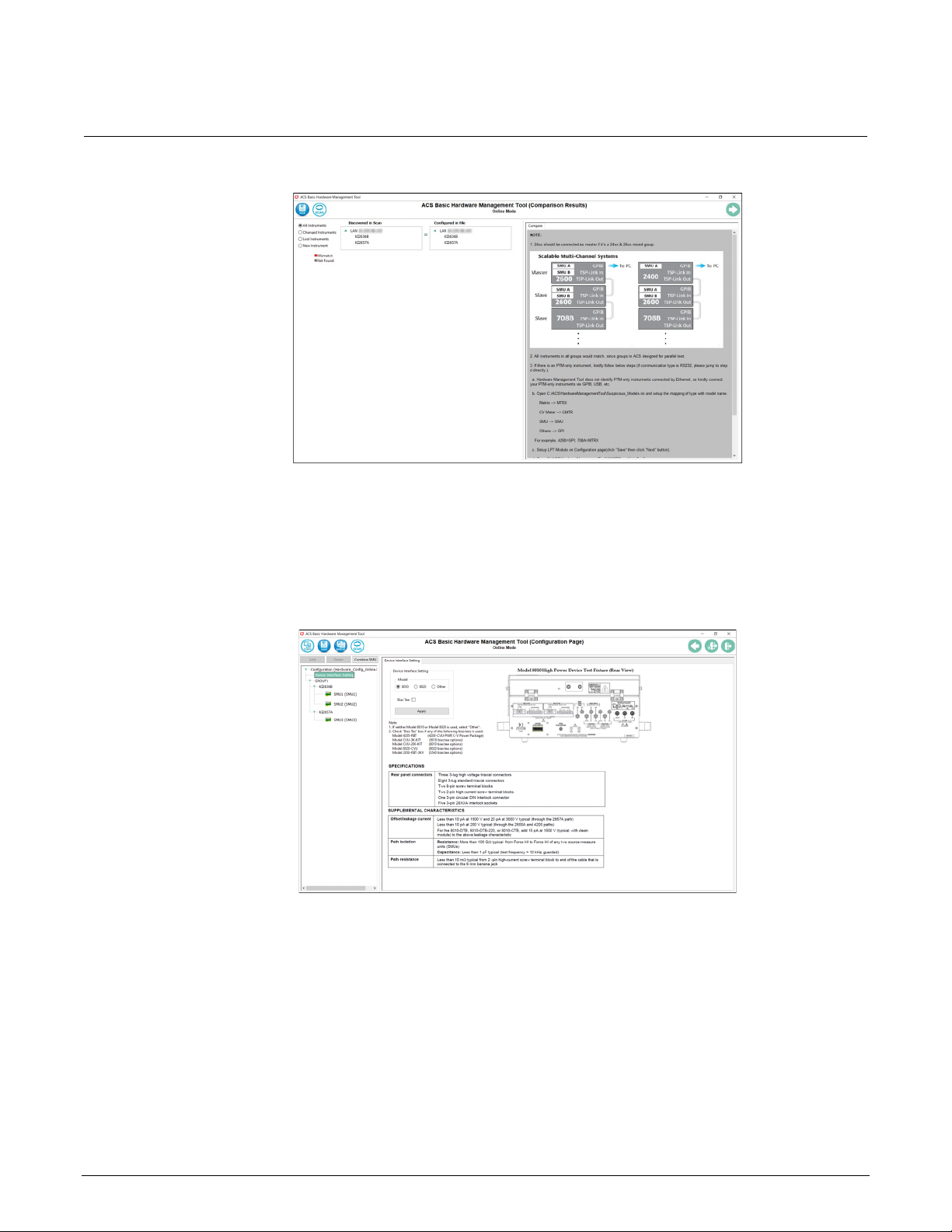
4. Select Scan. ACS Basic compares the instruments that were previously configured with the
present online instrument configuration. When the scan is complete, the Comparison Results
dialog is displayed, as shown in the following figure.
3-6 PCT-900-01 Rev. B August 2022
Page 22
Series 2600
Getting started with ACS Basic
-PCT-xB Parametric Curve Tracer User's Manual Section 3:
Figure 7: Comparison results
5. Verify the instruments. If you need to delete an instrument, right-click the instrument and select
Delete.
6. Select Save. The Configuration Page (Online Mode) opens.
7. Select Device Interface Setting. The information shown in the following figure is displayed.
Figure 8: Device Interface Setting
8. Select the Model of the device interface.
9. If you are using a bias tee (CVU-3K-Kit, CVU-200-KIT, 8020-CVU, or Model 4205-RBT), select
Bias Tee.
10. Select Apply.
PCT-900-01 Rev. B August 2022 3-7
Page 23
Section
User's Manual
3: Getting started with ACS Basic Series 2600-PCT-xB Parametric Curve Tracer
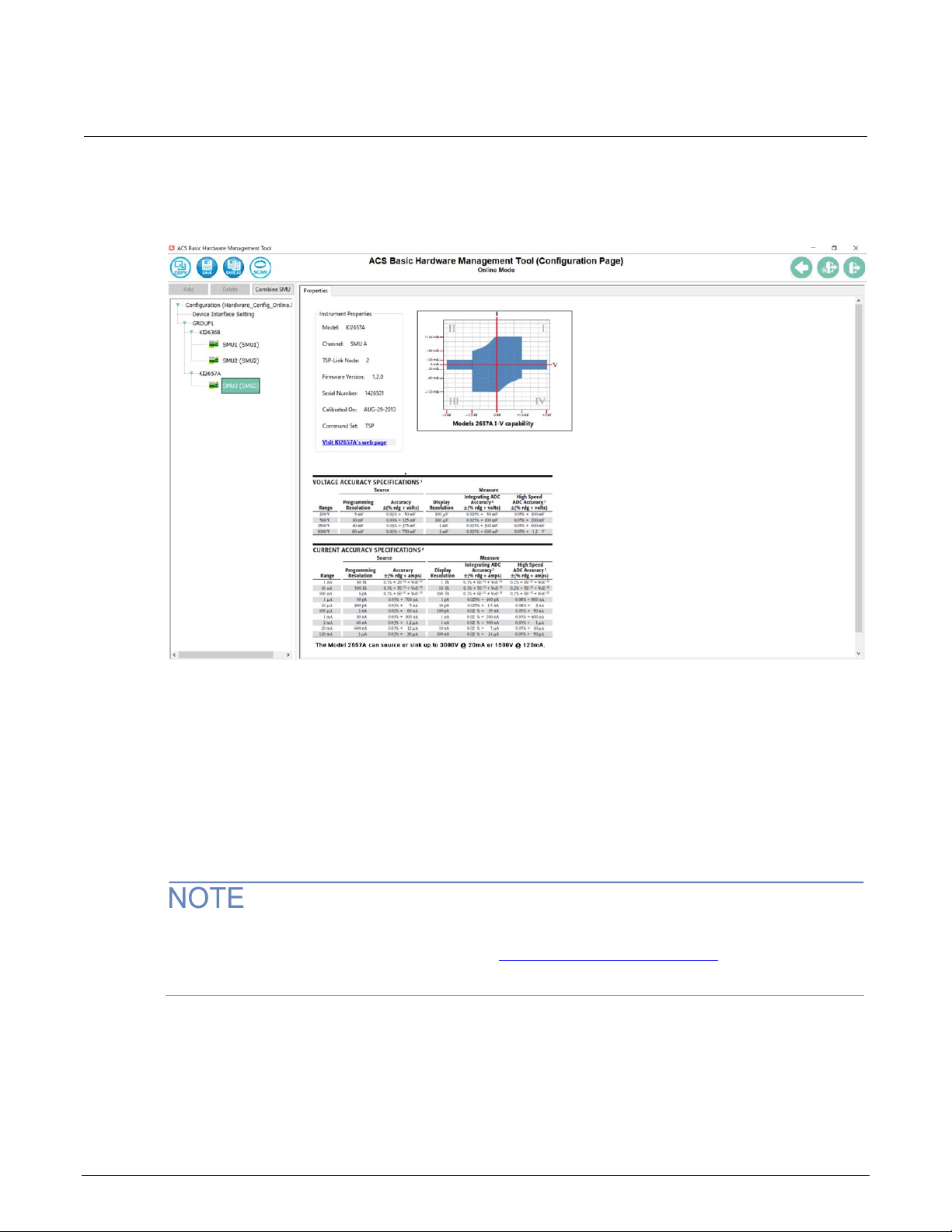
11. To set up the instruments, select an instrument from the left pane. An example of the
Configuration Page with a 2657A selected is shown in the following figure.
Figure 9: Configuration Page of the Hardware Management Tool
12. From this page, you can:
Add an instrument: Select Add. The instrument must be connected to the test system.
Delete an instrument: Select the instrument in the tree and select Delete.
Combine SMU instruments: Select the SMU instruments and select Combine SMU.
13. Select Save.
14. Close the Hardware Management Tool.
15. Restart ACS Basic.
ACS Basic automatically assigns the SMU numbers. The numbers differ based on your PCT
configuration and TSP-Link node numbers. See Assign TSP-Link node numbers (on page 3-2
) for
the recommended TSP-Link configuration.
3-8 PCT-900-01 Rev. B August 2022
Page 24

Series 2600
ted with ACS B asic
-PCT-xB Parametric Curve Tracer User's Manual Section 3: Getting star
For more information on using the Hardware Management Tool, refer to the ACS Basic
documentation.
If one or more SMUs are missing:
• Ensure that the GPIB adapter is securely attached to instrument and is working.
• Ensure that all instruments are powered on.
• Ensure that all TSP-Link cables are secure.
After checking the instruments, select Scan to scan the hardware configuration again.
Start ACS Basic
FATAL ERROR POSSIBLE. To avoid fatal errors to instruments, never start the ACS Basic
software until all the instruments have completed self-testing. If you are using Series 2600
and 2600B instruments with TSP-Link, always power-on the subordinate instruments first and
then the master. Since the master scans through all the linked subordinate instruments, it
must be powered on after all the subordinate machines are turned on, or errors may occur
when you start ACS Basic.
Before you open the ACS Basic software, make sure that all instruments are turned on and all selftests have completed.
To start the ACS software:
1. Select the ACS software icon on the desktop of your computer. The User Login dialog opens, as
shown in the following figure.
Figure 10: User login
PCT-900-01 Rev. B August 2022 3-9
Page 25

Section
User's Manual
3: Getting started with ACS Basic Series 2600-PCT-xB Parametric Curve Tracer
2. Type a user name and password in the User Name and Password fields. The default user name
is ACSADMIN; however, there is no default password.
3. Select OK. The software start window opens.
4. You can create more than one new user account at this time. To create a new account, select
New User. To change the password, select Change Password.
When you start the ACS Basic software, the startup time depends on how many instruments are in
t
he hardware configuration group. For example, if there are several instruments, the startup time
is longer.
ACS Basic test mod es
ACS Basic has three test modes: SingleMode, MultiMode, and TraceMode.
In SingleMode, ACS Basic opens and runs a single test on a single device at a time.
In MultiMode, you can create multiple test modules on one or more devices and organize them into a
single project. For example, MultiMode can perform multiple tests on a single device (target
application) or multiple tests on multiple devices (secondary use case). You can work with external
instruments such as DMMs and switches in MultiMode much easier than in any other mode.
TraceMode provides interactive operation with a SMU. TraceMode is useful for quickly checking the
operating boundaries of a device and for verifying its basic functionality.
In the following sections of this manual, you will learn how to perform common power semiconductor
tests in MultiMode and in TraceMode.
3-10 PCT-900-01 Rev. B August 2022
Page 26

Off-state characteristics ..........................................................4-34
I-V applications for power MOSFETs
In this section:
Section overview and equipment requirements ........................4-1
On-state characteristics ............................................................4-1
Section overview and equipment requirements
This section provides step-by-step instructions to use the Parametric Curve Tracer (PCT) to perform
common tests on a sample power MOSFET device. These tests include collecting family of curves
) on a power MOSFET and measuring leakage current (I
(V
ds-Id
) using the ACS Basic software.
dss
Section 4
The following instructions are tailored to the 2600-PCT-4B, which has both high voltage and high
current capability. However, the test parameters can be adjusted to suit the PCT configuration and
instrumentation that you have.
The PCT is provided with a sample test device, located in the PCT-DOC-KIT box of the “Open Me
First” box. The sample device is a 1000 V MOSFET and is available from onsemi as part number
FQH8N100C. You can download a datasheet for this part from the manufacturer's website at
onsemi.com (onsemi.com/
This section refers to SMUs that are numbered as suggested in Assign TSP-Link node numbers (on
page 3-2). Your configuration may vary.
).
On-state characterist ics
Configure the test fixture
The PCT supports either the Keithley Instruments Model 8010 or Model 8010 test fixtures. For
instructions on how to connect instruments to the 8010 or 8020, refer to Instruments and connections
(on page 2-1). To make connections to the device, see the following procedure for your test fixture.
Page 27
Section
User's Manual
4: I-V applications for power MOSFETs Series 2600-PCT-xB Parametric Curve Tracer
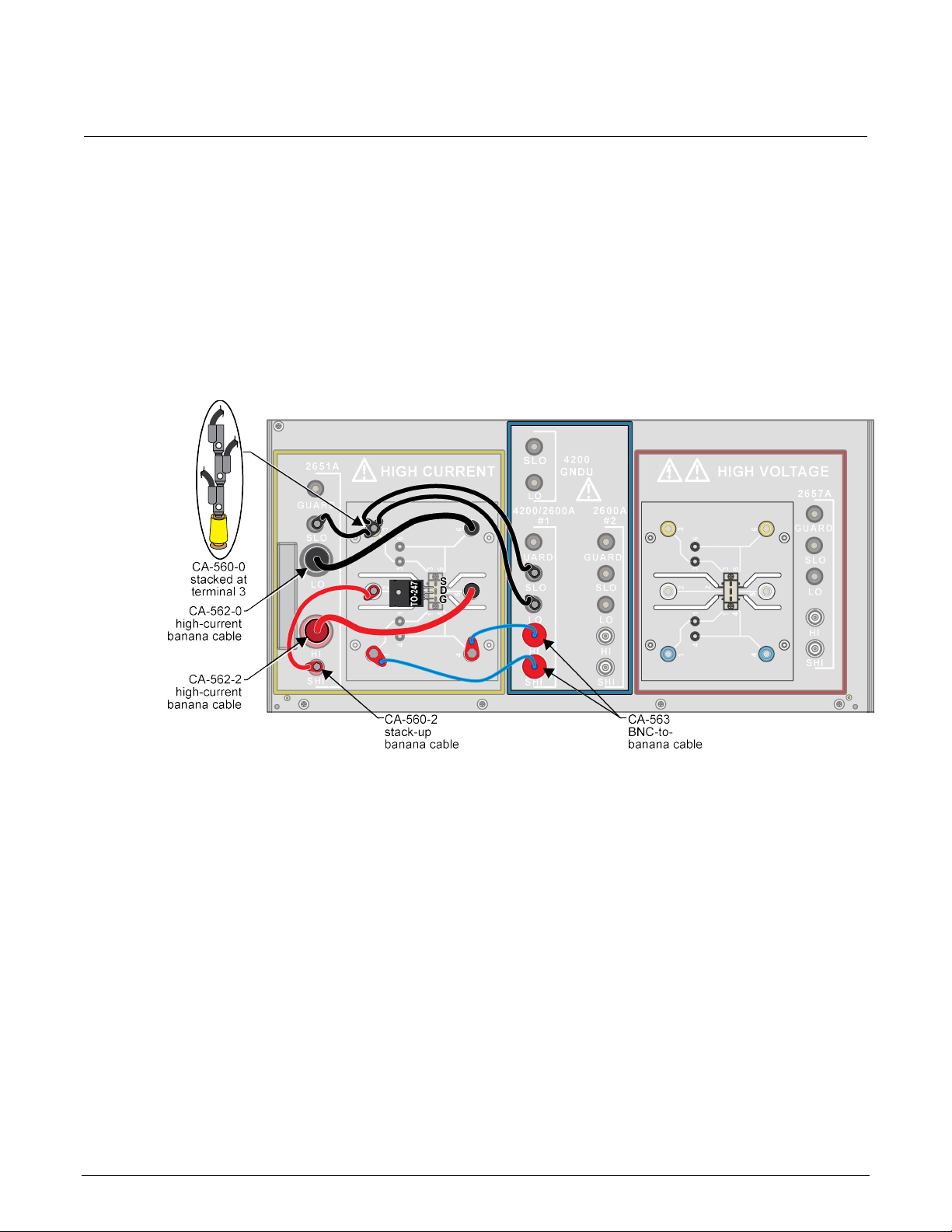
To configure the Model 8010 test fixtur e:
1. On the High Current side of the fixture, insert the test device into the test socket. Place the device
with the Gate pin closest to the front of the test fixture.
2. Wire the test fixture as shown in the following figure:
Connect the 2651A HI and SHI signals to the Drain terminal.
Connect the 2600A #1 HI and SHI signals to the Gate terminal.
Connect the LO and SLO signals from both SMUs to the Source terminal.
Figure 11: Three-terminal DUT with one or two 2651A instruments and Series 2600A
instrument connected
4-2 PCT-900-01 Rev. B August 2022
Page 28
Series 2600
V applications for power MOSFETs
-PCT-xB Parametric Curve Tracer User's Manual Section 4: I-
To configure the Model 8020 test fixtur e:
1. Wire the test fixture as shown in the following figure:
Connect both COMMON LO, SLO signals and the COMBINED 2651 LO signal to the Source
terminal of the device.
Connect the COMBINED 2651 SHI and HI signals to the Drain terminal of the device.
Connect both 2600/4200 SHI and HI signals to the Gate terminal of the device.
Figure 12: 8020 test fixture confi g uration (device side)
PCT-900-01 Rev. B August 2022 4-3
Page 29

Section
User's Manual
4: I-V applications for power MOSFETs Series 2600-PCT-xB Parametric Curve Tracer
Collecting I-V curves in TraceMode
TraceMode allows you to generate rapid visual results of device characteristics and to have real-time
control of one of the test parameters. This example application instructs you on how to collect a family
of curves on a MOSFET device.
These instructions demonstrate how to do the following tasks:
• Configure TraceMode
• Gather a family of curves on a MOSFET using TraceMode
• View and save data in TraceMode
An overview of the steps to do the test are:
1. Enter TraceMode of ACS Basic
2. Load the IdVd_StepVg test for the nPowerMOSFET device into the project
3. Configure the settings to match the DUT
4. Run the test
5. View and save the data
TraceMode supports the Series 2400, Series 2600B, and the Series 2650A SMUs. However, you
cannot connect a Series 2400 and a Series 2600B instrument to the same device. If you are using a
Series 2400 on one device terminal, you must use a Series 2400 instrument on the other device
terminals. TraceMode only supports the SCPI protocol for Series 2400 SMUs.
You can use a Series 2600B and a Series 2650A instrument in any combination.
TraceMode provides interactive control of SMU instruments to achieve real-time performance. Only
Series 2600B instruments (Models 2601B, 2602B, 2611B, 2612B, 2635B, or 2636B), Series 2650A
(Models 2651A or 2657A) and Series 2400 instruments (Models 2400, 2401, 2410, 2420, 2425, 2440)
are supported. ACS Basic can perform dc and pulse tests on Series 260 0B and 2650 A instr um ents in
TraceMode, but it can only perform dc measurements on Series 2400 instruments.
4-4 PCT-900-01 Rev. B August 2022
Page 30
Series 2600
V applications for power MOSFETs
-PCT-xB Parametric Curve Tracer User's Manual Section 4: I-
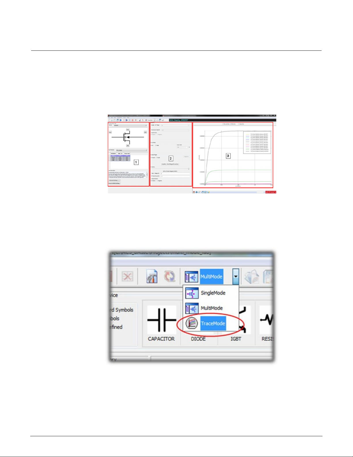
See the following figure. The GUI includes:
1. Device setting: Used to map the SMU, select the test module, and set the advanced settings.
2. Test setting: Used to set the test information when the test module is enabled.
3. Trace Test Data: Used to show the test result.
Figure 13: TraceMode GUI
To collect curves in TraceMode:
1. Launch ACS Basic.
2. From the MultiMode menu, select TraceMode.
Figure 14: Select TraceMode
PCT-900-01 Rev. B August 2022 4-5
Page 31

Section
User's Manual
4: I-V applications for power MOSFETs Series 2600-PCT-xB Parametric Curve Tracer
3. From Device, select nPowerMOSFET.
Figure 15: Select nPowerMOSFET
4. From Test Modules, select IdVd_StepVg. The test loads with default settings and sample data.
Figure 16: Selecting IdVd_Ste pVg
4-6 PCT-900-01 Rev. B August 2022
Page 32

Series 2600
V applications for power MOSFETs
-PCT-xB Parametric Curve Tracer User's Manual Section 4: I-
5. Connect a SMU to the device terminal by selecting the button next to the device terminal and
selecting the appropriate SMU. In the following example, SMU 4 is connected to the
Drain terminal.
Figure 17: Selecting a device terminal for SMU assignment
6. Select the SMU resource to connect to this device terminal. In this example, the high current
SMU (2651A, SMU 4) is connected to the Drain.
Figure 18: SMU 4 settings
PCT-900-01 Rev. B August 2022 4-7
Page 33

Section
User's Manual
4: I-V applications for power MOSFETs Series 2600-PCT-xB Parametric Curve Tracer
7. Select Ok.
8. Repeat these steps for the remaining device terminals. For this example, connect 2636A Channel
A (SMU1) to the gate and connect the Source to the GND terminal, which represents the
Common LO terminal.
9. Change the Stepping values. In this example, the gate SMU steps from 5 V to 7 V in 0.5 V
increments. Therefore, set the Number of Steps to 5, the Offset Value to 5 V, the Max Source
Value (V) to 7, and the Step Direction to Positive, as shown in the following figure.
Figure 19: Stepping settings
10. For Acquire/Trigger, select Repeat, as shown in the follow ing fig ur e. The Acquire/Trigger option
selects whether the sweep runs once or repeatedly in force mode.
Figure 20: Force Mode setting
11. Move the Sweeping slider to 0% so that no voltage is applied to the DUT when you start the test,
as shown in the following figure.
12. For this example, chang e the Peak Vol tag e to 10 and make sure that t he Sw eep Direc tio n
is Positive.
4-8 PCT-900-01 Rev. B August 2022
Page 34

Series 2600
V applications for power MOSFETs
-PCT-xB Parametric Curve Tracer User's Manual Section 4: I-
Figure 21: Sweeping slider at 0 percent of peak voltage
13. Select the Advanced Settings button near the lower-left part of the application window to display
the Advanced Settings dialog, as shown in the following figure.
Figure 22: Advanced Settings dialog
PCT-900-01 Rev. B August 2022 4-9
Page 35

Section
User's Manual
4: I-V applications for power MOSFETs Series 2600-PCT-xB Parametric Curve Tracer
The Advanced Settings are automatically configured based upon the type of test being run.
However, values can be changed to accommodate the DUT.
14. Adjust the following Advanced Settings:
Sense Mode: Remote for the Gate and Drain SMU
On the drain, change Compliance to 10 A and Meas Range to 10 A
On the gate, change the Compliance to 100 mA
Change the Duty Cycle to 5%
The pulse duty cycle of the pulses impacts the update rate of the display. Using a lower duty cycle
lows higher current without thermal stress to the device. However, a lower duty cycle means that
al
the display does not update as quickly as in this example.
15. Select OK.
16. Select Run to begin the test.
Figure 23: Run icon
17. Move the Sweeping slider to adjust the peak voltage. Notice that the I-V curves sweep out further
as you move the slider right.
4-10 PCT-900-01 Rev. B August 2022
Page 36

Series 2600
V applications for power MOSFETs
-PCT-xB Parametric Curve Tracer User's Manual Section 4: I-
Figure 24: Test results
You can also use the arrows keys on the keyboard to adjust the slider. The up and down arrow keys
result in coarse changes in the sweeping voltage of 10% of peak voltage The left and right arrow
keys result in fine changes in the sweeping voltage of 1% of peak voltage.
18. To stop the test, select Stop at the top of the application window.
Configure a fixed plot
As you increase the sweep voltage, the graph automatically scales to fit the collected data into
the plot.
To change the graph to be fixed:
1. Right-click in the plot, then select Plot and Axis Settings.
PCT-900-01 Rev. B August 2022 4-11
Page 37

Section
User's Manual
4: I-V applications for power MOSFETs Series 2600-PCT-xB Parametric Curve Tracer
Figure 25: Select Plot and Axis Settings
2. Select Axis Settings.
Figure 26: Plot Settings dialog
3. Change the following options for the X-Axis Scale:
a. Clear Auto
b. Change the X-Axis Scale Min to 0
c. Change the X-Axis Scale Max to 10
4-12 PCT-900-01 Rev. B August 2022
Page 38

Series 2600
ns for power MOSFETs
-PCT-xB Parametric Curve Tracer User's Manual Section 4: I-V applicatio
4. Make the following modifications to the Y-Axis Scale:
a. Clear Auto
b. Change the Y-Axis Scale Min to 0
c. Change the Y-Axis Scale Max to 10
5. Change the X and Y Axis Title Text:
a. Re-name the X-Axis title to Vds (Volts)
b. Re-name the Y-Axis title to Ids (Amps)
6. Select Save.
Collecting I-V curves in MultiMode
In SingleMode and MultiMode, you program all test parameters before test operation. Tests run
without operator intervention or interaction. These modes are useful for generating precise data on
the DUT and for extracting device parameters from the data set.
In this example application, you collect a family of curves on the sample MOSFET.
This example application demonstrates how to do the following tas ks :
• Create a MultiMode project in ACS Basic
• Add tests to the project using the built-in test libraries
• Configure a test in MultiMode
• View, append, and save data in MultiMode
To make connections to the test fixture for this test, refer to Configure the test fixture (on page 4-1
To do the test:
1. Place the DUT into the Model 8010 test fixture and configure the connections
2. Enter MultiMode of ACS Basic
3. Create a new MultiMode project
4. Load the IdVd_StepVg test for the nPowerMOSFET device into the project
5. Configure the settings to match the device under test
6. Run the test
7. Save the data
).
PCT-900-01 Rev. B August 2022 4-13
Page 39

Section
User's Manual
4: I-V applications for power MOSFETs Series 2600-PCT-xB Parametric Curve Tracer
MultiMode GUI overview
The configuration navigator, shown in the following figure, has the following logical hierarchy:
• Project
Device 1
Test module 1 (ITM, STM, or PTM)
Test module 2 (ITM, STM, or PTM)
Device 2
Test module 1 (ITM, STM, or PTM)
Test module 2 (ITM, STM, or PTM)
Figure 27: MultiMode user interface
The configuration navigator is the primary interface for building, editing, and viewing a project plan,
and for specifying and accessing each project plan component.
4-14 PCT-900-01 Rev. B August 2022
Page 40

Series 2600
V applications for power MOSFETs
-PCT-xB Parametric Curve Tracer User's Manual Section 4: I-
When you select a navigator component (test or device) you can do the following:
• Add a new component
• Delete an existing component
• Run the tests associated with this component
Selecting a navigator component opens the configuration interface on the right panel, which includes
settings, test results, and status information.
Typical project plan components of the configuration navigator are shown in the following figure.
Figure 28: Project plan components of the configuration navigator view
The project plan components include:
• Project Plan: Defines and sequences all devices tested, and all tests and operations to be
performed at each. It typically corresponds to one die on a wafer.
• Device Plan: Defines and sequences all tests for a specific device, including transistors, diodes,
and resistors.
• ITM: Completely defines a parametric test without programming, using a series of configured
graphical user interfaces that show data numerically and graphically in real time. Provides for the
PCT-900-01 Rev. B August 2022 4-15
display of both raw data and analyzed data.
Page 41

Section
User's Manual
4: I-V applications for power MOSFETs Series 2600-PCT-xB Parametric Curve Tracer
Set up a new MultiMode project
You can use the ACS Basic MultiMode to create multiple test modules on one or more devices and
organize them into a single project. You can work with external instruments, such as DMMs and
switches, in MultiMode more easily than in any other mode.
MultiMode starts with the most recently used MultiMode project. In this application, you replace it with
a new project.
To set up a new MultiMode project:
1. Start ACS Basic, if it is not already open.
2. From the Mode Selection list, select MultiMode.
Figure 29: Select MultiMode
3. From the File menu, select New.
Figure 30: Create a new project
4-16 PCT-900-01 Rev. B August 2022
Page 42

Series 2600
V applications for power MOSFETs
4. Select No to the prompt to save the current project. The New Test Project dialog opens, as
shown in the following figure.
Figure 31: New Test Project dialog
-PCT-xB Parametric Curve Tracer User's Manual Section 4: I-
5. In the Project Name field, enter a project name.
6. Select OK.
When the new project opens, the project navigation pane on the left is empty and the test libraries
area fills the remainder of the window. The test libraries area is the easiest way to add devices and
tests to your project.
PCT-900-01 Rev. B August 2022 4-17
Page 43

Section
User's Manual
4: I-V applications for power MOSFETs Series 2600-PCT-xB Parametric Curve Tracer
Figure 32: Project navigation and test libraries
Add the IdVd_StepVg test to the project
To add the IdVd_StepVg test to the project:
1. From the Select a Device pane, select nPowerMOSFET.
Figure 33: nPowerMOSFET selected on the Select a Device pane
4-18 PCT-900-01 Rev. B August 2022
Page 44

Series 2600
V applications for power MOSFETs
-PCT-xB Parametric Curve Tracer User's Manual Section 4: I-
2. Select the IdVd_StepVg test from the Test Modules pane at the bottom left of the window.
Figure 34: Select the IdVd_StepVg test module
3. Select Add Test. The device and test are added to your project tree.
Figure 35: Device and test added to project tree
PCT-900-01 Rev. B August 2022 4-19
Page 45

Section
User's Manual
4: I-V applications for power MOSFETs Series 2600-PCT-xB Parametric Curve Tracer
4. In the Project Tree, select the device nPowerMOSFET_26. The Device Settings dialog opens.
Figure 36: Device Settings dialog
In the Device Settings dialog, you can configure which SMU is connected to which pin of the device,
set the SMU sense mode, and assign a name to the pad. This SMU mapping applies to all tests in the
project tree under the dev ice.
When you add the test to the project, ACS Basic automatically assigns SMUs to the pins. You should
verify that the pin assignments are correct:
• Make sure that the high current SMU (for this example, Model 2651A, SMU 4) is connected to
the drain
• Make sure that the 2636A Channel A (SMU 1) is connected to the gate
• Make sure that both the gate and drain are configured for remote sense
• Make sure that the source terminal is connected to GND
4-20 PCT-900-01 Rev. B August 2022
Page 46

Series 2600
V applications for power MOSFETs
-PCT-xB Parametric Curve Tracer User's Manual Section 4: I-
Configu re the test
You configure the settings each test in the Test Definition dialog. From this dialog, you can set every
aspect of how your test runs. Many of the settings are preconfigured, but you need to make some
changes for this application.
You can check your SMU assignments by hovering the mouse cursor over t
he pad numbers in the
device diagram.
This section refers to SMUs that are numbered as suggested in Assign TSP-Link node numbers (on
page 3-2). Your configuration may vary.
To set up the IV curve test:
1. In the project navigator, select the test named IdVd_StepVg.
2. For SMU4 (drain), confirm that Compliance is set to 10 A.
3. For SMU4 (drain), set the Meas. Range to 10A.
4. For SMU1 (gate), confirm that Compliance is set to 0.1 A.
5. For SMU4 (drain), double-click the Source Settings cell to open the Sweep V Settings dialog.
Figure 37: Sweep V settings
6. Set the Mode to Linear.
7. Set the Start value to 0.
8. Set the Stop value to 10.
9. Set the Step value to 0.1.
10. Set the Base value to 0.
11. Select OK.
PCT-900-01 Rev. B August 2022 4-21
Page 47

Section
User's Manual
4: I-V applications for power MOSFETs Series 2600-PCT-xB Parametric Curve Tracer
Figure 38: Modified Sweep V Setting s
12. For SMU1 (gate), double-click the Source Settings cell to open the Step V Settings dialog.
13. Set the Start value to 5.
14. Set the Stop value to 7.
15. Set the Points value to 5.
16. Set the Base value to 0.
17. Select OK.
Figure 39: Modified Step V Settings
4-22 PCT-900-01 Rev. B August 2022
Page 48

Series 2600
MOSFETs
Run the test
-PCT-xB Parametric Curve Tracer User's Manual Section 4: I-V applications for power
The Data tab contains the data from the last time the test was run. Because this test is new, it
contains sample data. When the test is run, the new data overwrites the sample data.
To run the test:
1. Select the Data tab of the Test dialog.
2. Select Run ( ) to start the test. Once data collection is complete, the test stops.
3. At the top of the Data tab, select Plot Only to get a better view of the plot.
4. Select Data Only to get a better view of the data in the spreadsheet.
5. Select Plot and Data to return to the dual view.
6. As the test runs and ACS Basic collects data, the curves are displayed on the graph.
Figure 40: Test result curves and data
You can also run the test without overwriting the existing data. This is useful for comparing data
between two devices or doing a before and after comparison after making some changes to the test
settings or device connections.
PCT-900-01 Rev. B August 2022 4-23
Page 49

Section
User's Manual
4: I-V applications for power MOSFETs Series 2600-PCT-xB Parametric Curve Tracer
To run the test and append data:
1. Select Append Run to start the test.
After the test runs, the appended data is graphed on the plot next to the original data. An additional
tab on the datasheet holds the new data. Since no changes were made, the curves of the appended
data should align with the original curves. If the curves align, this is a good indicator that you are
making settled measurements. If they do not align, there could be a problem with your test
configuration.
Save project and data
Figure 41: Append Run icon
When you save the project with Save All, all your test settings and collected data are saved with it so
the next time you load ACS Basic and open the test, your settings and data are still there. You can
also save the data to a Microsoft Excel spreadsheet or to a .csv file for analysis in another
application.
To save a project:
1. Select Save in the top toolbar.
Figure 42: Save a project
To save test data:
1. Above the plot in the test results window, select the data to be saved. You can select Plot and
Data, Plot Only, or Data Only. For this example, select Plot and Data.
Figure 43: Data view options in test results
4-24 PCT-900-01 Rev. B August 2022
Page 50

Series 2600
V applications for power MOSFETs
-PCT-xB Parametric Curve Tracer User's Manual Section 4: I-
2. Select Save at the bottom of the plot.
Figure 44: Save test data
3. From Save as Type, select the data type. The default is .xls. You can also save
in .csv, .png, .ps, .eps., and .svg formats.
Figure 45: Save to File dialog
PCT-900-01 Rev. B August 2022 4-25
Page 51

Section
User's Manual
4: I-V applications for power MOSFETs Series 2600-PCT-xB Parametric Curve Tracer
Digitizing pulses and improving timing
For many devices, you must adjust the measurement timing to produce good test results.
In particular, you may need to increase the pulse width to give the test signal more time to settle
before making the measurement. Often test engineers use an oscilloscope to see what the pulse
looks like and determine the proper pulse width and measurement time from this information. The
Series 2650A SMUs feature a built-in 18-bit fast analog-to-digital (ADC) converter that can digitize the
pulse without the need of the oscilloscope. This application demonstrates how to use the fast ADC to
digitize the output of the SMU to examine the shape of the pulse.
To introduce you to digitizing pulses, this application shows you how to:
• Adjust timing settings
• Digitize the pulse from a data point in the test
• Plot dig itized data
• Read the digitized pulse to configure the correct timing settings
To make connections to the test fixture for this test, refer to Configure the test fixture (on page 4-1).
To do the test, you do the following steps:
1. Configure the test fixture.
2. Load the IdVdStepVg test that was created in MultiMode (on pa ge 4-4).
3. Configure the test to digitize a pulse.
4. Configure the plot to display the digitized data.
5. Adjust the timing settings and then use the digitize function to review the changes.
Configure the test to digitize a pulse
For instructions on creating a new IdVd_StepVg test, refer to Add the IdVd_StepVg test to the project
(on page 4-18).
To configure the test to digitize a pulse:
1. Select the IdVd_StepVg test.
2. Select the Definition tab.
3. Select Timing, highlighted in the following figure, to open the ITM Timing dialog.
4-26 PCT-900-01 Rev. B August 2022
Page 52

Series 2600
V applications for power MOSFETs
Speed
Adjust the measurement aperture of the integrating ADC and configure any averaging.
Timing settings for outputting dc signals. Most of these settings can only be changed if
the test is running under DC Only Mode, which is set in the Test Definition dialog.
General Parameters
Settings for the period between data points and for when the measurement is made
relative to the start of the period.
Pulse Timing
1 and 2 Parameters
Configure the Pulse Width of any pulse signals and specify when the pulse is output
relative to the start of the period.
Force Mode
Assignments
Displays which SMUs are assigned to each of the three timing configurations.
-PCT-xB Parametric Curve Tracer User's Manual Section 4: I-
Figure 46: Timing button
Configure the General Timing tab settings
You configure the SMU output timing and measurements in the General Timing tab of the ITM Timing
dialog. The following table describes each of the setting categories.
ITM Timing dialog, General Timing tab setting categories
Category Function
DC Parameters
PCT-900-01 Rev. B August 2022 4-27
Page 53

Section
User's Manual
Start of a period
End of a period
Measurement trigger time
Measurement aperture (area)
4: I-V applications for power MOSFETs Series 2600-PCT-xB Parametric Curve Tracer
Figure 47: ITM Timing dialog
In the previous figure, the output preview is based on the settings for the DC Parameters, Pulse
Timing 1 Parameters, and Pulse Timing 2 Par a met er s.
Preview output definitions
1
2
3
4
To ensure good pulsed measurements, this aperture must be in the width of the pulse. It should also
be placed far enough from the leading edge of the pulse to ensure that the signal has settled before
the measurement is started.
To capture digitized pulse waveforms, capture the timing data by selecting Timestamp Enabled in the
General Parameters.
You will also enable and configure Pulse Transient Mode, as described in the following topic.
4-28 PCT-900-01 Rev. B August 2022
Page 54

Series 2600
V applications for power MOSFETs
Configure the Pulse Transient tab settings
You enable and configure the digitize feature of the 2650A Series SMUs in the Pulse Transient tab of
the ITM Timing dialog. The following table describes each of the settings.
Figure 48: ITM Timing dialog, Pulse Transient tab
-PCT-xB Parametric Curve Tracer User's Manual Section 4: I-
PCT-900-01 Rev. B August 2022 4-29
Page 55

Section
User's Manual
Pulse Transient
Mode
Digitizes a single point of the step/sweep sequen ce. S ele ctin g Pulse Tra ns ient Mo de
enables the mode and the controls to configure the mode.
Single Point /
Controls whether ACS Basic goes directly to the select ed step/sweep point and digitizes it or
Differences in data is most commonly due to device self-heating.
Transient Start /
Transient End
Sets the start and end times of the digitizing window and are relative to the start of the
period. This window is represented in the previous figure by the blue shaded area.
Sweep Point / Step
Point
Selects which points in the step/sweep sequence you want to digitize.
SMU Info
Displays the programed levels for the SMUs at that step and sweep point. By default, the
there is 7 V on the Gate and 10 V on the Drain.
Force Mode
Assignments
Displays which SMUs have been assigned to each of the three timing configurations.
4: I-V applications for power MOSFETs Series 2600-PCT-xB Parametric Curve Tracer
ITM Timing, Pulse Transient tab setting categories
Setting Function
Entire step/sweep
if it runs through the entire step/sweep sequence to digitize the selected point. To get to
results quickly, use Single Point. If the data you get when going directly to the point differs
from the data you get when you run the entire sweep, select Entire step/sweep to see results
that most closely match the output when the full test is run.
last point of the step/sweep sequence is selected, which corresponds to the point where
To configure the digitize feature:
1. Select Step and Sweep points that correspond to a Gate voltage of 6.5 V and a Drain voltage of
5 V.
2. Select Pulse Transient Mode to enable pulse transient mode.
3. Set Transient Start to 0.
4. Set Transient End to 1e-3.
5. Set the Sweep Point to 51.
6. Set the Step Point to 4.
7. Select OK.
8. Select the Data tab.
9. Select Run ( ) to start the test. The results are displayed on the Data tab and resemble the
following figure.
4-30 PCT-900-01 Rev. B August 2022
Page 56

Series 2600
V applications for power MOSFETs
-PCT-xB Parametric Curve Tracer User's Manual Section 4: I-
Figure 49: ITM Timing test results
By default, the graph for the IdVd_StepVg test is configured to show current versus voltage. To get a
scope-like view, you need to plot the signals versus time. Since the default plot is already setup for
displaying the IV curves of the device, it is preferable to not make any changes to its settings when
trying to view the digitized data. Instead, create a new plot to graph the data.
Create a new plot
1. Select the plot icon, then select New Plot.
Figure 50: New Plot
2. In the XY Settings dialog, scroll down to time(4).
3. For time(4), select X.
4. For V_Drain(4), select Y1.
5. For I_Drain(4), select Y2.
6. Select OK.
PCT-900-01 Rev. B August 2022 4-31
Page 57

Section
User's Manual
4: I-V applications for power MOSFETs Series 2600-PCT-xB Parametric Curve Tracer
Figure 51: XY Settings dialog
The digitized data now appears on a second plot to the right of the original. The voltage waveform is
shown on the plot in red and the current waveform is shown on the plot in blue.
Figure 52: New digitized data
4-32 PCT-900-01 Rev. B August 2022
Page 58

Series 2600
V applications for power MOSFETs
-PCT-xB Parametric Curve Tracer User's Manual Section 4: I-
Adjust the pulse timing set tin gs
When a waveform has been established, you can change some of the timing settings to observe
differences.
To change the timing settings:
1. Select the Definition tab.
2. Select Timing.
Figure 53: Timing example wave fo rm
In this test, the Drain is configured to use Pulse Timing 1 and the Gate is configured to use Pulse
Timing 2. The default settings have the rising edge of the Gate signal (Pulse Timing 2) 60 µs
before the rising edge of the Drain signal and the falling edge of both signals occurring at the
same time.
3. Change the Pulse Width of Pulse Timing 1 to 5e-4 (500 µs).
4. Change the Pulse Width of Pulse Timing 2 to 6e-4 (600 us).
5. Set the Measure Delay to 4e-4 (400 us).
6. Set the Period to 5e-3 (50 ms ).
7. Select OK.
8. Select the Data tab of the Test dialog.
9. Select Run ( ) to start the test.
PCT-900-01 Rev. B August 2022 4-33
Page 59

Section
User's Manual
4: I-V applications for power MOSFETs Series 2600-PCT-xB Parametric Curve Tracer
Figure 54: Graphed results
After you run the test, you should see a graph similar the one above. These results show that the
signal settles quickly, so dc measurements with these timing parameters should produce
repeatable measurements.
Off-state characteri st ics
Configure the test fixture
The PCT supports either the Keithley Instruments Model 8010 or Model 8010 test fixture. Follow one
of the following procedures depending on your test fixture.
To configure the Model 8010 test fixtur e:
1. On the High Voltage side of the Model 8010 test fixture, insert the test sample device into the test
socket. Place the device with the Gate pin closest to the front of the test fixture.
2. Wire the test fixture as shown in the following figure:
Connect the 2657A HI signal to the Drain terminal.
Connect the 4200/2600 #2 signal to the Gate terminal.
Connect the LO terminals of the 2657A and the 4200/2600 #2 signal to the Source terminal.
4-34 PCT-900-01 Rev. B August 2022
Page 60

Series 2600
V applications for power MOSFETs
-PCT-xB Parametric Curve Tracer User's Manual Section 4: I-
Figure 55: Leakage current measurement test fixture configuration
To configure the Model 8020 interface panel:
1. Wire the test fixture as shown in the following figure:
Connect the LO signal to the Source terminal of the device.
Connect the 2657 HI signal to the Drain terminal of the device.
Connect the 2600/4200 #1 HI signal to the Gate terminal of the device.
PCT-900-01 Rev. B August 2022 4-35
Page 61

Section
User's Manual
4: I-V applications for power MOSFETs Series 2600-PCT-xB Parametric Curve Tracer
Figure 56: Configuring the 8020 interface panel for leakage current measurement
4-36 PCT-900-01 Rev. B August 2022
Page 62

Series 2600
V applications for power MOSFETs
-PCT-xB Parametric Curve Tracer User's Manual Section 4: I-
Measuring leakage current in MultiMode
Characterizing a semiconductor device in its off-state includes leakage current measurements,
sourcing a voltage, and measuring a small current. These measurements req uir e sens itive equ ip men t
with proper guarding and shielding.
To introduce you to measuring leakage current, this application shows you how to use MultiMode to
perform an Idss test on a high-voltage MOSFET using the sample part provided in the PCT-DOC-KIT.
To do the test, you do the following steps:
1. Configure the connections to the device
2. Add the Idss test to the project
3. Configure the test settings to suit the DUT
4. Run the test and obtain the leakage current from the device
Add and configure the Idss tes t
To add and configure the Idss test:
1. In the Project Navigation Tree, select Project to display the Test Libraries.
Figure 57: Test Libraries
2. Select the nPowerMOSFET device from the Select a Device pane.
3. Select the IDSS test from t he Test Mod ules list.
4. Select Add Test to add the test to your project.
5. Select New device, then select OK. You now have the device nPowerMOSFET_26_1 in your
project tree.
PCT-900-01 Rev. B August 2022 4-37
Page 63

Section
User's Manual
4: I-V applications for power MOSFETs Series 2600-PCT-xB Parametric Curve Tracer
6. Right-click the device and select Rename.
7. Change the name to nPowerMOSFET_HV.
8. Press <Enter> to save the change.
Figure 58: New device in project navigation tree
9. Select the nPowerMOSFET_HV device.
10. Use Pads-SMUs mapping, then follow one of the next steps, depending on your test fixture.
For the Model 8010, attach SMU 3 (2657A) to the Drain and the SMU2 (2636B SMU B) to the
Gate
For the Model 8020, configure the SMU3 (2657A) to the Drain and SMU1 (2636B SMU A) to
the Gate
11. Set the Sense Mode for both SMUs to Local.
12. Configure the Source terminal to GND.
4-38 PCT-900-01 Rev. B August 2022
Page 64

Series 2600
V applications for power MOSFETs
-PCT-xB Parametric Curve Tracer User's Manual Section 4: I-
Figure 59: Device Settings dialog (Model 8020 connections)
13. Select the Idss test under the IGBT_26 device in the Project Navigation Tree.
14. Select the Definition tab.
15. Set the Source value to 1000 V.
Figure 60: Setting Source value to 1000 V
16. For the gate SMU (SMU 1 or SMU 2), set the source function to GND.
17. Set the compliance (current limit) of both SMUs to 1 mA.
18. Select measurement of current and voltage for SMU 3 (2657A).
If you want to profile the leakage current of the device as a function of voltage, set the source
unction to sweep V. Configure the sweep settings in the Source field.
f
PCT-900-01 Rev. B August 2022 4-39
Page 65

Section
User's Manual
4: I-V applications for power MOSFETs Series 2600-PCT-xB Parametric Curve Tracer
19. Select the Data tab.
Figure 61: Data tab
Sample data for the DSS test is displayed.
Figure 62: Data tab with sample DSS test data
The current through the device and the voltage across the device are plotted versus time on the
graph. This test works by sourcing the test voltage and taking many readings. The readings are then
averaged to give you a final value.
You can adjust the number of samples taken and averaged in the Timing dialog of the test. Under
General Parameters, enter the number of readings for #Sample. See the following figure.
4-40 PCT-900-01 Rev. B August 2022
Page 66

Series 2600
V applications for power MOSFETs
-PCT-xB Parametric Curve Tracer User's Manual Section 4: I-
Figure 63: Sample quantity adjustment
You can also configure the test to stop if the compliance (current limit) is reached. Select Stop on
Compliance to have the test automatically stop if any SMU reaches current limit.
PCT-900-01 Rev. B August 2022 4-41
Page 67

Section
User's Manual
4: I-V applications for power MOSFETs Series 2600-PCT-xB Parametric Curve Tracer
Run the test
Select Run ( ) to start the test.
Figure 64: Data and results of IDSS test
The data you collect should look similar to the data seen here. While the voltage data may appear
noisy at first, take note of the scale of the plot. You can simplify the plot by adjusting the scale for the
voltage readings in the Data tab.
4-42 PCT-900-01 Rev. B August 2022
Page 68

Series 2600
V applications for power MOSFETs
-PCT-xB Parametric Curve Tracer User's Manual Section 4: I-
To simplify the plot:
1. Right-click the graph and select Plot and Axis Settings.
Figure 65: Plot and Axis Settings
2. Select the Axis Settings tab.
3. For Y2, clear Auto.
4. Set the Min value to 999.55.
5. Set the Max value to 1000.55.
PCT-900-01 Rev. B August 2022 4-43
Page 69

Section
User's Manual
4: I-V applications for power MOSFETs Series 2600-PCT-xB Parametric Curve Tracer
Figure 66: Plot Settings dialog
6. Select Save.
You can improve the stability of the current measurements by adjusting the timing. Accurate low
current measurements typically involve significant settl ing tim e and lon ger inte gr at ion times .
To refine the Idss results:
1. Open the ITM Timing dialog by selecting Timing.
2. Set the Hold Time to 1 s.
3. Set the speed to Slow.
4. By default, auto delay is enabled, but you can add delay time. Set the Measure Delay to 0.25 s,
which sets the SMU to delay 250 ms beyond the auto delay time for increased settling. See the
following figure for an example.
4-44 PCT-900-01 Rev. B August 2022
Page 70

Serie
V applications for power MOSFETs
s 2600-PCT-xB Parametric Curve Tracer User's Manual Section 4: I-
Figure 67: ITM Timing dialog with settings
5. Select OK.
6. Select Run ( ).
7. Note the improved Idss results. Your refined results should be similar to those in the
following figure.
PCT-900-01 Rev. B August 2022 4-45
Page 71

Section
Manual
4: I-V applications for power MOSFETs Series 2600-PCT-xB Parametric Curve Tracer User's
Figure 68: Refined Idss results
The datasheet for the sample device specifies a 10 µA maximum value for Idss. The measured
leakage current should be much smaller than the specification. Such specifications are typically
created using traditional curve tracers, which have limited current measurement resolution and are
generally unable to measure currents less than 10 μA. If the measured value exceeds the
specification, the device is likely damaged. Verify connections and then re-test.
4-46 PCT-900-01 Rev. B August 2022
Page 72

................................................................................................5-64
Section 5
C-V applications on power MOSFETs
In this section:
Overview and requirements ......................................................5-1
Background of MOSFET capacitance measur eme nts ..............5-1
Safety precautions and discharge procedures ..........................5-4
Model 8010 connections .........................................................5-10
Model 8020 connections .........................................................5-15
Perform connection compensations on C-V measurement s ...5-20
Make a Ciss measurement .....................................................5-38
Make a Coss measurement ....................................................5-46
Make a Crss measurement .....................................................5-57
Optimizing Crss measurement connections for difficult measurements
Overview and requirements
This section descri bes circuit-level power MOSFET capacitance measurements on a device up to
3 kV using a Keithley Instruments Model 8020 with the optional 8020-CVU installed or the Model
8010 with the CVU-3K-KIT option and a 2600-PCT-3B with the PCT-CVU accessory unit.
See the Model 8010 and Model 8020 User Guides, available at tek.com/keithley
information on 2-terminal devices and for component-level capacitance measurements of power
MOSFETs.
, for connection
Background of MOSFET capacitance measurements
There are two different ways to look at the capacitance of three-terminal power semiconductor
devices such as MOSFETs, BJTs, and IGBTs: At the component level and at the circuit level. Looking
at the capacitances at the component level involves a characterization of capacitance between every
device terminal. Looking at the capacitance at the circuit-level involves a characterization of the
combination of component level capacitances.
As an example, the following figure illustrates the component level capacitances of a power
MOSFET.
Page 73

Section
User's Manual
5: C-V applications on power MOSFETs Series 2600-PCT-xB Parametric Curve Tracer
Figure 69: Component-level capacitances for power MOSFET
The following three figures illustrate the relationship between the component level and circuit-level
capacitances for a power MOSFET. Similar capacitance measurements can also be made for BJT
and IGBT devices.
Figure 70: Diagram of input capacitance for a power MOSFET
5-2 PCT-900-01 Rev. B August 2022
Page 74

Series 2600
V applications on power MOSFETs
-PCT-xB Parametric Curve Tracer User's Manual Section 5: C-
Figure 71: Diagram of output capacitance for a power MOSFET
Figure 72: Diagram of reverse transfer capacitance for a power MOSFET
Device capacitance typically varies with applied voltage. Complete characterization of the DUT
requires knowledge of the capacitance at the maximum rated voltage. The remainder of this section
reviews the safety precautions, connection diagrams between the instrumentation, the test fixtures,
and the DUT for high-voltage capacitance measurements.
PCT-900-01 Rev. B August 2022 5-3
Page 75

Section
User's Manual
5: C-V applications on power MOSFETs Series 2600-PCT-xB Parametric Curve Tracer
Safety precaut ions and discharg e procedures
Hazardous voltages may be present in the test system. To prevent electrical shock that could
cause injury or death, never make or break connection s to the instruments in the system
while the output is on. Power off the equi p m ent from the front panel or disconnect the main
power cord from the rear of the Series 2600-PCT-xB and discharge any energy storage
components (for example, capacitors or cables) before handling cables connected to the
outputs. Putting the equipment in standby mode does not guarantee that the outputs are not
powered if a hardware or software fault occurs.
Discharging bias tee capacitance in the Model 8010
The capacitance of the bias tees in the Model CVU-200-KIT and CVU-3K-KIT can hold charge.
Devices with sufficient capacitance can also hold charge. A shock hazard exists if a proper discharge
is not performed and you open the Model 801 0 cov er and touc h one of the ins trument or device
terminals in the fixture. Never assume that the safety interlock discharges the system.
The Model 2657A SMU is programmed in ACS Basic to safely discharge the bias tee and device
capacitance after completing a high-voltage C-V test. However, an operator error, a power outage, or
an unforeseen event can leave a dangerous charge in the system. Therefore, the Model CVU-3K-KIT
includes the 8020-DP High-Voltage Discharge Probe. Use this discharge probe to manually discharge
the bias tee capacitance and system capacitance within the Model 8010 by touching the banana
jacks and BNC connectors inside of the fixture.
See the following figure for an overview of the Model 8020-DP High Voltage Discharge Probe.
5-4 PCT-900-01 Rev. B August 2022
Page 76

Series 2600
V applications on power MOSFETs
-PCT-xB Parametric Curve Tracer User's Manual Section 5: C-
Figure 73: Model 8020-DP High Voltage Discharge Probe
Perform system capacitance discharge with the Model 8020-DP High Voltage Discharge Probe:
1. Connect the Model 8020-DP ground connection cable to an unused protective earth screw on
one of the bias tees.
Figure 74: 8020-DP connected to bias tee protective earth screw
Do not stack cable connectors on the protective ground screw. Connect only to an
unused screw.
PCT-900-01 Rev. B August 2022 5-5
Page 77

Section
User's Manual
5: C-V applications on power MOSFETs Series 2600-PCT-xB Parametric Curve Tracer
2. Open the lid of the Model 8010 test fixture.
3. While holding the 8020-DP by the handgrip only, use the probe tip to contact the terminals on the
device test board that connect the HI and SHI terminals of the 2657A, as shown the following two
figures.
Figure 75: Contacting the HI terminal of the Model 8010 test board
Figure 76: Contacting the SHI terminal of the Model 8010 test board
5-6 PCT-900-01 Rev. B August 2022
Page 78

Series 2600
V applications on power MOSFETs
-PCT-xB Parametric Curve Tracer User's Manual Section 5: C-
4. If there is no cable connected to the HI and SHI connections of the 2657A, use the discharge
probe to contact the center conductors of the HI and SHI BNC connectors.
Figure 77: Contacting the HI BNC conne ctor of the Model 8010 test fixture
5. Maintain contact for at least 1 second to safely discharge system capacitance.
6. Contact the GUARD banana jack of the Model 2657A.
Figure 78: Contacting the GUARD ban ana connector of the Model 8010 test board
7. Maintain contact for at least 1 second.
8. Repeat discharge procedure on the HI and SHI terminals of the Model 2600B or 4200A within the
Model 8010 fixture.
PCT-900-01 Rev. B August 2022 5-7
Page 79

Section
User's Manual
5: C-V applications on power MOSFETs Series 2600-PCT-xB Parametric Curve Tracer
Discharging bias tee capacitance within the Model 8020
The 8020-CVU option for the Model 8020 has internal capacitance that can hold charge. A shock
hazard exists if a proper discharge is not performed and the user removes the 8020 top cover or in
other ways accesses a live terminal in the system. Never assume the safety interlock discharges the
system.
Be sure to use the SMU to discharge the capacitance properly after each test and before removing
the top cover of the 8020 or accessing live terminals in the system. The Model 2657A SMU is
programmed in ACS Basic to safely discharge the bias tee and device capacitance after completing a
high-voltage CV test. A user error or another unforeseen event, such as a power outage, can leave a
dangerous charge in the system. Therefore, the Model 8020 with the 8020-CVU option includes a
high voltage discharge probe, Model 8020-DP. Use this discharge probe to manually discharge the
bias tee capacitance and system capacitance before making adjustments on the 8020 main board or
at the device interface.
See the following figure for an overview of the Model 8020-DP High Voltage Discharge Probe.
Figure 79: Model 8020-DP High Voltage Discharge Probe
5-8 PCT-900-01 Rev. B August 2022
Page 80

Series 2600
V applications on power MOSFETs
-PCT-xB Parametric Curve Tracer User's Manual Section 5: C-
Perform system capacitance discharge with the Model 8020-DP High Voltage Discharge Probe:
1. Connect the Model 8020-DP High Voltage Discharge Probe ground connection cable to an
unused protective earth screw on the Model 8020. Examples are shown in the following figure.
Figure 80: Protective earth (safety ground) screw locations on the Model 8020
Do not stack cable connectors on the protecti ve ground screw. Connect only to an unused
screw.
2. Remove the top cover of the Model 8020 High Power Interface Panel.
3. While holding the 8020-DP by the handgrip only, use the probe tip to contact each of the posts at
notes 1a, 1b, and 2 on the Model 8020 main board for the high-voltage channel and each of the
200 V channels. See the following figure.
Figure 81: Contacting nodes on the Model 8020 main board
4. Maintain contact for at least 1 second to safely discharge system capacitance.
PCT-900-01 Rev. B August 2022 5-9
Page 81

Section
User's Manual
5: C-V applications on power MOSFETs Series 2600-PCT-xB Parametric Curve Tracer
Discharge system capacitance from SMU front panel interface
If you are controlling the SMUs from the front-panel interface, a best practice is to discharge system
capacitance with the SMU output on. Configure the SMU to force 0 V and measure current with a
current limit of at least 1 mA. A current measurement of approximately 0 mA indicates a proper
discharge. The Keithley Instruments ACS Basic software executes this discharge procedure after
completing a high-voltage CV test. ACS Basic sets the Model 2657A output to 0 V with a current limit
of 1 mA and holds for 1 second before turning off the output. See the following figure for an
illustration.
Figure 82: Model 2657A executing discharge
Model 8010 connections
Refer to the following figures to connect your SMUs, PCT-CVU, and CVU-3K-KIT to the Model 8010.
You need to reference these drawings for both the connection compensation and capacitance
measurement procedures.
The ground wires must be attached to a known protecti ve earth (safety ground) before
tu
rning on the instruments. Failure to attach the ground wires to a known protective earth
(safety ground) may result in electric shoc k.
The following figures rely on a SMU per bias tee. With the Model 2600-PCT-1B and 2600-PCT-2B,
there are not enough appropriate SMUs to connect to bias tees. For these configurations, connect
the force terminal of the GNDU of the PCT-CVU to the bias tee that connects to the Source terminal
of the FET or the Emitter terminal of the BJT or IGBT.
Model 8010 Crss test connections
The following figure shows the Model 8010 SMU, PCT-CVU, and CVU-3K-KIT connections for the
Crss test.
5-10 PCT-900-01 Rev. B August 2022
Page 82

Series 2600
V applications on power MOSFETs
-PCT-xB Parametric Curve Tracer User's Manual Section 5: C-
Figure 83: Model 8010 connections for the Crss and Cgd tests
PCT-900-01 Rev. B August 2022 5-11
Page 83

Section
User's Manual
5: C-V applications on power MOSFETs Series 2600-PCT-xB Parametric Curve Tracer
Model 8010 Ciss test connections
The following figure shows the Model 8010 SMU, PCT-CVU, and CVU-3K-KIT connections for the
Ciss test.
Figure 84: Instrument connections to the Model 8010 for the Ciss test
5-12 PCT-900-01 Rev. B August 2022
Page 84

Series 2600
V applications on power MOSFETs
-PCT-xB Parametric Curve Tracer User's Manual Section 5: C-
Model 8010 Coss test connections
The following figure shows the Model 8010 SMU, PCT-CVU, and CVU-3K-KIT connections for the
Coss test.
Figure 85: Instrument connections to the Model 8010 for the Coss test
PCT-900-01 Rev. B August 2022 5-13
Page 85

Section
User's Manual
5: C-V applications on power MOSFETs Series 2600-PCT-xB Parametric Curve Tracer
Model 8010 connections to the device for Crss
The following figure shows the Model 8010 connections to a power MOSFET for the Crss test.
Figure 86: Model 8010 device connections for Crss test
5-14 PCT-900-01 Rev. B August 2022
Page 86

Series 2600
V applications on power MOSFETs
-PCT-xB Parametric Curve Tracer User's Manual Section 5: C-
Model 8010 connections to the device for Ciss and Coss
Figure 87: Model 8010 device connections for Ciss and Coss tests
Model 8020 connections
The following figures rely upon a SMU per bias tee. With the Model 2600-PCT-1B and 2600-PCT-2B,
there are not enough appropriate SMUs to connect to bias tees. For these configurations, connect
the force terminal of the GNDU of the PCT-CVU to the bias tee that connects to the Source terminal
of the FET or the Emitter terminal of the BJT or IGBT.
PCT-900-01 Rev. B August 2022 5-15
Page 87

Section
User's Manual
5: C-V applications on power MOSFETs Series 2600-PCT-xB Parametric Curve Tracer
Model 8020 Crss test connections
The following figure shows the Model 8020 connections for the Crss test.
Figure 88: Instrument connections to the Model 8020 for the Crss test
5-16 PCT-900-01 Rev. B August 2022
Page 88

Series 2600
OSFETs
-PCT-xB Parametric Curve Tracer User's Manual Section 5: C-V applications on power M
Model 8020 Ciss test connections
The following figure shows the Model 8020 connections for the Ciss test.
Figure 89: Instrument connections to the Model 8020 for the Ciss test
PCT-900-01 Rev. B August 2022 5-17
Page 89

Section
User's Manual
5: C-V applications on power MOSFETs Series 2600-PCT-xB Parametric Curve Tracer
Model 8020 Coss connections
The following figure shows the Model 8020 connections for the Coss test.
Figure 90: Instrument connections to the Model 8020 for the Coss test
5-18 PCT-900-01 Rev. B August 2022
Page 90

Series 2600
V applications on power MOSFETs
-PCT-xB Parametric Curve Tracer User's Manual Section 5: C-
Model 8020 test connections to the device
The following figure shows the Model 8020 connections to the device under test for Ciss, Coss, and
Crss measurements.
Figure 91: Model 8020 connections to the device
PCT-900-01 Rev. B August 2022 5-19
Page 91

Section
User's Manual
5: C-V applications on power MOSFETs Series 2600-PCT-xB Parametric Curve Tracer
Perform connection compensations on C-V measurements
Stray capacitance, resistance, and inductance in the test setup can cause measurement errors.
These errors vary with setup and their impact varies with frequency. To remove these errors from the
measurement, perform connection compensation. Because there are connection changes between
capacitance measurements of a power MOSFET, each capacitance measurement requires a
separate open and short compensation. ACS Basic stores correction data for each capacitance
measurement. This section describes how to perform compensation for the three circuit-level
capacitance measurements: Ciss, Coss, and Crss.
Perform open and short compensation whenever the test configuration changes. This includes
cabling and adapter changes and changes to the bias tee configurations.
Though compensation can be performed individually for each capacitance measurement, this section
steps you through the open and short compensations for all the circuit-level capacitance parameters
(Ciss, Coss, and Crss).
Ciss compensation
Before you begin connection compensations, make sure that you have connected your instruments
correctly. See Model 8010 Ciss test connections (on page 5-12) or Model 8020 Ciss test connections
(on page 5-17).
Perform open compensation for the Ciss measurement:
1. If you are using the Model 8010, make sure that no device is inserted in the device socket in the
test fixture (see the following figure), then close the lid of the test fixture.
Figure 92: Internal 8010 connections for Ciss open compensation
5-20 PCT-900-01 Rev. B August 2022
Page 92

Series 2600
V applications on power MOSFETs
-PCT-xB Parametric Curve Tracer User's Manual Section 5: C-
2. If you are using the Model 8020, remove the DUT or lift the probes on a probe station to
disconnect from the device.
3. In ACS Basic, open MultiMode if it is not already open. To set up a MultiMode project, refer to
Set
up a new MultiMode project (on page 4-16).
4. Select Tools and select CVU Compensation, as shown in the following figure.
Figure 93: Tools > CVU Compensation
5. The CVU Connection Compensation dialog is displayed, as shown in the following figure.
PCT-900-01 Rev. B August 2022 5-21
Page 93

Section
User's Manual
5: C-V applications on power MOSFETs Series 2600-PCT-xB Parametric Curve Tracer
Figure 94: CVU Connection Compensation dialog
If this CV connection compensation dialog does not appear, make sure that your device interface
settings are correct in the hardware configurator. The bias tee checkbox must be selected. Refer to
Getting started with ACS Basic (on page 3-1
) for more details.
6. Select the appropriate CVU Cable Length according to the cables that you have. 1.5 m cables are
supplied with the PCT-CVU.
7. Under 3-terminal measurement, for Level Setting, select Circuit-level Parameters.
8. Select Measure Open Ciss, Cib, Cies. The Measure Open for Ciss, Cib, Cies dialog is
displayed, as shown in the following fig ure. Se lec t Help to display detailed information for
compensation connections and device terminal terminology.
5-22 PCT-900-01 Rev. B August 2022
Page 94

Series 2600
V applications on power MOSFETs
-PCT-xB Parametric Curve Tracer User's Manual Section 5: C-
Figure 95: Measure Open dialog
9. Select Start to begin the open compensation measurement. A progress dialog is displayed. Open
compensation may take up to 90 seconds to complete.
10. When the measurement is complete, the following dialog is displayed. Select OK to confirm.
Figure 96: Compensation complete dialog
11. Leave the CVU Connection dialog open for the remaining compensation procedures.
PCT-900-01 Rev. B August 2022 5-23
Page 95

Section
User's Manual
5: C-V applications on power MOSFETs Series 2600-PCT-xB Parametric Curve Tracer
Perform short compensation for Ciss measurement:
1. If you are using the Model 8010, make sure that no device is inserted in the device socket in the
test fixture.
2. Use a banana jumper to short the gate and source terminals, as shown in the following figure,
then close the lid of the test fixture.
Figure 97: Internal 8010 connections for Ciss short compensation
3. If you are using the Model 8020, remove or disconnect from the device and place a short
between the connections to the gate and source terminals. Note the location of the short in the
following figure.
5-24 PCT-900-01 Rev. B August 2022
Page 96

Series 2600
V applications on power MOSFETs
-PCT-xB Parametric Curve Tracer User's Manual Section 5: C-
Figure 98: Ciss measurement, s ho rt compensation
PCT-900-01 Rev. B August 2022 5-25
Page 97

Section
User's Manual
5: C-V applications on power MOSFETs Series 2600-PCT-xB Parametric Curve Tracer
4. Select Measure Short Ciss, Cib, Cies.
Figure 99: CVU Connection Compensation dialog
5. The Measure Short for Ciss, Cib, Cies dialog is displayed, as shown in the following figure. Select
Help to display detailed information for short compensation connections and device terminal
terminology.
5-26 PCT-900-01 Rev. B August 2022
Page 98

Series 2600
V applications on power MOSFETs
-PCT-xB Parametric Curve Tracer User's Manual Section 5: C-
6. Select Start to begin the short compensation measurement. A progres s dialog is displ ay ed. Sh ort
compensation may take up to 90 seconds to complete.
7. When the measurement is complete, select OK to confirm.
8. Leave the CVU Connection dialog open for the remaining compensation procedures.
Coss compensation
Before you begin connection compensations, make sure that you have connected your instruments
correctly. See Model 8010 Coss test connections (on page 5-13) and Model 8020 Coss test
connections (on page 5-18).
Perform open compensation for Coss measurement:
1. If you are using the Model 8010, make sure that no device is inserted in the device socket in the
test fixture, as shown in the following figure, then close the lid of the test fixture.
Figure 100: Internal 8010 connections for Coss open compensation
9. Remove the shorting wire to proceed to the next connection compensation measurement.
2. If you are using the Model 8020, remove the DUT or lift the probes on a probe station to
disconnect from the device.
3. In the CVU Connection Compensation dialog of the ACS Basic software, select Measure Open
Coss, Cob, Coes, shown in the following figure.
PCT-900-01 Rev. B August 2022 5-27
Page 99

Section
User's Manual
5: C-V applications on power MOSFETs Series 2600-PCT-xB Parametric Curve Tracer
Figure 101: CVU Connection Compensation dial og
4. The Measure Open for Coss, Cob, Coes dialog is displayed. Select Help to display detailed
information for compensation connections and device terminal terminology.
Figure 102: Measure Open dialog
5-28 PCT-900-01 Rev. B August 2022
Page 100

Series 2600
V applications on power MOSFETs
-PCT-xB Parametric Curve Tracer User's Manual Section 5: C-
5. Select Start to begin the open compensation measurement.
6. A progress dialog is displayed. Open compensation may take up to 90 seconds to complete.
When the measurement is complete, the follow in g dial og is disp lay ed.
Figure 103: Compensation complete dialog
7. Select OK. Leave the CVU Connections Compensation dialog open for the remaining
compensation procedures.
Perform short compensation for Coss measurement:
1. If you are using the Model 8010, make sure that no device is inserted in the device socket in the
test fixture.
2. Short the Source and Drain terminals using a banana jumper, as shown in the following figure,
then close the lid of the Model 8010.
Figure 104: Internal 8010 connections for C oss short compensation
PCT-900-01 Rev. B August 2022 5-29
 Loading...