

Page 1

Series 2600B
System SourceMeter® Instrument
User's Manual
tek.com/keithley
2600B
S-900-01 Rev. A August 2021
*P2600BS-900-01A*
2600B
S-900-01A
Page 2

System SourceMeter® instrument
Series 2600B
User's Manual
Page 3

© 2021, Keithley Instruments, LLC
Cleveland, Ohio, U.S.A.
All rights reserved.
Any unauthorized reproduction, photocopy, or use of the information herein, in whole or in part,
without the prior written approval of Keithley Instruments, LLC, is strictly prohibited.
These are the original instructions in English.
TSPTM and TSP-LinkTM are trademarks of Keithley Instruments, LLC. All Keithley Instruments
product names are trademarks or registered trademarks of Keithley Instruments, LLC. Other brand
names are trademarks or registered trademarks of their respective holders.
The Lua 5.0 software and associated documentation files are copyright © 1994 - 2015, Lua.org,
PUC-Rio. You can access terms of license for the Lua software and associated documentation at
the Lua licensing site (https://www.lua.org/license.html).
Microsoft, Visual C++, Excel, and Windows are either registered trademarks or trademarks of
Microsoft Corporation in the United States and/or other countries.
Document number: 2600BS-900-01 Rev. A August 2021
Page 4

Safety precautions
The following safety precautions should be observed before using this product and any associated instrumentation. Although
some instruments and accessories would normally be used with nonhazardous voltages, there are situations where hazardous
conditions may be present.
This product is intended for use by personnel who recognize shock hazards and are familiar with the safety precautions required
to avoid possible injury. Read and follow all installation, operation, and maintenance information carefully before using the
product. Refer to the user documentation for complete product specifications.
If the product is used in a manner not specified, the protection provided by the product warranty may be impaired.
The types of product users are:
Responsible body is the individual or group responsible for the use and maintenance of equipment, for ensuring that the
equipment is operated within its specifications and operating limits, and for ensuring that operators are adequately trained.
Operators use the product for its intended function. They must be trained in electrical safety procedures and proper use of the
instrument. They must be protected from electric shock and contact with hazardous live circuits.
Maintenance personnel perform routine procedures on the product to keep it operating properly, for example, setting the line
voltage or replacing consumable materials. Maintenance procedures are described in the user documentation. The procedures
explicitly state if the operator may perform them. Otherwise, they should be performed only by service personnel.
Service personnel are trained to work on live circuits, perform safe installations, and repair products. Only properly trained
service personnel may perform installation and service procedures.
Keithley products are designed for use with electrical signals that are measurement, control, and data I/O connections, with low
transient overvoltages, and must not be directly connected to mains voltage or to voltage sources with high transient
overvoltages. Measurement Category II (as referenced in IEC 60664) connections require protection for high transient
overvoltages often associated with local AC mains connections. Certain Keithley measuring instruments may be connected to
mains. These instruments will be marked as category II or higher.
Unless explicitly allowed in the specifications, operating manual, and instrument labels, do not connect any instrument to mains.
Exercise extreme caution when a shock hazard is present. Lethal voltage may be present on cable connector jacks or test
fixtures. The American National Standards Institute (ANSI) states that a shock hazard exists when voltage levels greater than
30 V RMS, 42.4 V peak, or 60 VDC are present. A good safety practice is to expect that hazardous voltage is present in any
unknown circuit before measuring.
Operators of this product must be protected from electric shock at all times. The responsible body must ensure that operators
are prevented access and/or insulated from every connection point. In some cases, connections must be exposed to potential
human contact. Product operators in these circumstances must be trained to protect themselves from the risk of electric shock. If
the circuit is capable of operating at or above 1000 V, no conductive part of the circuit may be exposed.
Do not connect switching cards directly to unlimited power circuits. They are intended to be used with impedance-limited
sources. NEVER connect switching cards directly to AC mains. When connecting sources to switching cards, install protective
devices to limit fault current and voltage to the card.
Before operating an instrument, ensure that the line cord is connected to a properly-grounded power receptacle. Inspect the
connecting cables, test leads, and jumpers for possible wear, cracks, or breaks before each use.
When installing equipment where access to the main power cord is restricted, such as rack mounting, a separate main input
power disconnect device must be provided in close proximity to the equipment and within easy reach of the operator.
For maximum safety, do not touch the product, test cables, or any other instruments while power is applied to the circuit under
test. ALWAYS remove power from the entire test system and discharge any capacitors before: connecting or disconnecting
cables or jumpers, installing or removing switching cards, or making internal changes, such as installing or removing jumpers.
Do not touch any object that could provide a current path to the common side of the circuit under test or power line (earth)
ground. Always make measurements with dry hands while standing on a dry, insulated surface capable of withstanding the
voltage being measured.
Page 5

For safety, instruments and accessories must be used in accordance with the operating instructions. If the instruments or
accessories are used in a manner not specified in the operating instructions, the protection provided by the equipment may be
impaired.
Do not exceed the maximum signal levels of the instruments and accessories. Maximum signal levels are defined in the
specifications and operating information and shown on the instrument panels, test fixture panels, and switching cards.
When fuses are used in a product, replace with the same type and rating for continued protection against fire hazard.
Chassis connections must only be used as shield connections for measuring circuits, NOT as protective earth (safety ground)
connections.
If you are using a test fixture, keep the lid closed while power is applied to the device under test. Safe operation requires the use
of a lid interlock.
If a screw is present, connect it to protective earth (safety ground) using the wire recommended in the user documentation.
The symbol on an instrument means caution, risk of hazard. The user must refer to the operating instructions located in the
user documentation in all cases where the symbol is marked on the instrument.
The symbol on an instrument means warning, risk of electric shock. Use standard safety precautions to avoid personal
contact with these voltages.
The symbol on an instrument shows that the surface may be hot. Avoid personal contact to prevent burns.
The symbol indicates a connection terminal to the equipment frame.
If this symbol is on a product, it indicates that mercury is present in the display lamp. Please note that the lamp must be
properly disposed of according to federal, state, and local laws.
The WARNING heading in the user documentation explains hazards that might result in personal injury or death. Always read
the associated information very carefully before performing the indicated procedure.
The CAUTION heading in the user documentation explains hazards that could damage the instrument. Such damage may
invalidate the warranty.
The CAUTION heading with the symbol in the user documentation explains hazards that could result in moderate or minor
injury or damage the instrument. Always read the associated information very carefully before performing the indicated
procedure. Damage to the instrument may invalidate the warranty.
Instrumentation and accessories shall not be connected to humans.
Before performing any maintenance, disconnect the line cord and all test cables.
To maintain protection from electric shock and fire, replacement components in mains circuits — including the power
transformer, test leads, and input jacks — must be purchased from Keithley. Standard fuses with applicable national safety
approvals may be used if the rating and type are the same. The detachable mains power cord provided with the instrument may
only be replaced with a similarly rated power cord. Other components that are not safety-related may be purchased from other
suppliers as long as they are equivalent to the original component (note that selected parts should be purchased only through
Keithley to maintain accuracy and functionality of the product). If you are unsure about the applicability of a replacement
component, call a Keithley office for information.
Unless otherwise noted in product-specific literature, Keithley instruments are designed to operate indoors only, in the following
environment: Altitude at or below 2,000 m (6,562 ft); temperature 0 °C to 50 °C (32 °F to 122 °F); and pollution degree 1 or 2.
To clean an instrument, use a cloth dampened with deionized water or mild, water-based cleaner. Clean the exterior of the
instrument only. Do not apply cleaner directly to the instrument or allow liquids to enter or spill on the instrument. Products that
consist of a circuit board with no case or chassis (e.g., a data acquisition board for installation into a computer) should never
require cleaning if handled according to instructions. If the board becomes contaminated and operation is affected, the board
should be returned to the factory for proper cleaning/servicing.
Safety precaution revision as of June 2018.
Page 6

Introduction .............................................................................................................. 1-1
Welcome .............................................................................................................................. 1-1
Extended warranty ............................................................................................................... 1-1
Contact information .............................................................................................................. 1-1
Customer documentation ..................................................................................................... 1-2
Product software and drivers ............................................................................................... 1-3
General ratings ..................................................................................................................... 1-4
Installation ................................................................................................................ 2-1
Introduction .......................................................................................................................... 2-1
Cooling vents ....................................................................................................................... 2-1
Turning the instrument on and off ........................................................................................ 2-2
Placing a 2600B in standby ................................................................................................. 2-3
Warmup period ..................................................................................................................... 2-3
Line frequency configuration ................................................................................................ 2-4
System information .............................................................................................................. 2-4
Instrument description ............................................................................................ 3-1
Controls, indicators, and connectors .................................................................................... 3-1
Front panel ................................................................................................................................ 3-1
Rear panel................................................................................................................................. 3-5
Menu overview ................................................................................................................... 3-12
Menu navigation ...................................................................................................................... 3-12
Menu trees .............................................................................................................................. 3-12
Setting values .......................................................................................................................... 3-19
Beeper ................................................................................................................................ 3-21
Displayed error and status messages ................................................................................ 3-21
Display operations .............................................................................................................. 3-22
Display mode .......................................................................................................................... 3-22
Display functions and attributes .............................................................................................. 3-23
Display features ...................................................................................................................... 3-24
Display messages ................................................................................................................... 3-25
Input prompting ....................................................................................................................... 3-29
Indicators................................................................................................................................. 3-31
Local lockout ........................................................................................................................... 3-32
Load test menu ....................................................................................................................... 3-32
Running a test from the front panel ......................................................................................... 3-34
Connecting the USB flash drive ......................................................................................... 3-34
Using the web interface...................................................................................................... 3-35
How to access the web interface ............................................................................................. 3-35
Web interface Welcome page ................................................................................................. 3-36
Use the ID button to identify the instrument ............................................................................ 3-37
Table of contents
Page 7

Table of contents Series 2600B System SourceMeter® instrument User's Manual
Change the IP configuration through the web interface .......................................................... 3-37
Set the instrument password ................................................................................................... 3-38
Using the virtual front panel..................................................................................................... 3-38
View buffer data using the web interface ................................................................................ 3-39
Download reading buffer data using the web interface ........................................................... 3-40
Using TSB Embedded ............................................................................................................. 3-41
Send individual commands using the web interface ................................................................ 3-41
Review events in the LXI Event Log ........................................................................................ 3-41
Help ......................................................................................................................................... 3-44
Operation .................................................................................................................. 4-1
Basic operation .................................................................................................................... 4-1
Source-measure capabilities ................................................................................................ 4-1
Voltage and current ................................................................................................................... 4-2
Limits .................................................................................................................................... 4-2
Setting the limit from the front panel .......................................................................................... 4-4
Setting the limit from a remote interface .................................................................................... 4-4
Sink operation ...................................................................................................................... 4-5
Setting the sink mode using the front panel .............................................................................. 4-6
Setting the sink mode from a remote interface .......................................................................... 4-6
DUT test connections ........................................................................................................... 4-6
Input/output connectors ............................................................................................................. 4-8
2-wire local sensing connections ............................................................................................. 4-12
4-wire remote sensing connections ......................................................................................... 4-12
Contact check connections ..................................................................................................... 4-14
Guarding and shielding ........................................................................................................... 4-16
Interlock................................................................................................................................... 4-23
Test fixture .............................................................................................................................. 4-24
Floating a SMU ....................................................................................................................... 4-26
Front-panel source-measure procedure ............................................................................ 4-28
Step 1: Select and set the source level ................................................................................... 4-28
Step 2: Set the compliance limit .............................................................................................. 4-28
Step 3: Select the measurement function and range .............................................................. 4-29
Step 4: Turn the output on ...................................................................................................... 4-29
Step 5: Observe readings on the display. ............................................................................... 4-29
Step 6: Turn the output off....................................................................................................... 4-29
Sense mode selection ........................................................................................................ 4-30
Front-panel sense mode selection .......................................................................................... 4-30
Remote interface sense mode selection ................................................................................. 4-30
Output-off modes ............................................................................................................... 4-31
Normal output-off mode .......................................................................................................... 4-31
High-impedance output-off mode ............................................................................................ 4-31
Zero output-off mode ............................................................................................................... 4-31
Output-off function ................................................................................................................... 4-32
Output-off limits (compliance) .................................................................................................. 4-33
Remote programming output-off states quick reference ......................................................... 4-34
Maintenance ................................ ................................................................ ............. 5-1
Introduction .......................................................................................................................... 5-1
Line fuse replacement .......................................................................................................... 5-1
Page 8

Series 2600B System SourceMeter® instrument User's Manual Table of contents
Front-panel tests .................................................................................................................. 5-3
Keys test ................................................................................................................................... 5-3
Display patterns test .................................................................................................................. 5-3
Upgrading the firmware ........................................................................................................ 5-4
Using TSB to upgrade the firmware .......................................................................................... 5-5
Displaying the serial number ................................................................................................ 5-6
Next steps ................................................................................................................. 6-1
Additional 2600B information ............................................................................................... 6-1
Page 9

In this section:
Welcome .................................................................................. 1-1
Extended warranty ................................................................... 1-1
Contact information ................................ .................................. 1-1
Customer documentation ......................................................... 1-2
Product software and drivers.................................................... 1-3
General ratings ......................................................................... 1-4
Welcome
Thank you for choosing a Keithley Instruments product. The Series 2600B System SourceMeter®
instrument provides manufacturers of electronic components and semiconductor devices with an
instrument that combines source and measurement capabilities in a single instrument called a
source-measure unit (also called a SMU). This combination simplifies test processes by eliminating
synchronization and connection issues associated with multiple instrument solutions. A 2600B
provides a scalable, high throughput, highly cost-effective solution for precision dc, pulse, and low
frequency ac source-measure testing that also maintains code compatibility throughout the Series
2600B SourceMeter instruments.
This manual describes basic operation for the Models 2601B, 2602B, 2604B, 2611B, 2612B, 2614B,
2634B, 2635B, and 2636B.
Extended warranty
Additional years of warranty coverage are available on many products. These valuable contracts
protect you from unbudgeted service expenses and provide additional years of protection at a fraction
of the price of a repair. Extended warranties are available on new and existing products. Contact your
local Keithley Instruments office, sales partner, or distributor for details.
Contact information
If you have any questions after you review the information in this documentation, please contact your
local Keithley Instruments office, sales partner, or distributor. You can also call the Tektronix
corporate headquarters (toll-free inside the U.S. and Canada only) at 1-800-833-9200. For worldwide
contact numbers, visit tek.com/contact-us.
Section 1
Introduction
Page 10

Section 1: Introduction Series 2600B System SourceMeter® instrument User's Manual
1-2 2600BS-900-01 Rev. A / August 2021
Customer documentation
The documentation for the 2600B includes a Quick Start Guide, User's Manual, and Reference
Manual. A Quick Start Guide is provided as a hard copy with the instrument. You can also access it
from tek.com/keithley as an Adobe Acrobat PDF file.
• Quick Start Guide: Provides unpacking instructions, describes basic connections, and reviews
basic operation information. If you are new to Keithley Instruments equipment, refer to the Quick
Start Guide to take the steps needed to unpack, set up, and verify operation.
• User's Manual: Includes installation, instrument description, operation, and maintenance
information.
• Reference Manual: Includes advanced operation topics and maintenance information.
Programmers looking for a command reference and users looking for an in-depth description of
how the instrument works (including troubleshooting and optimization) should refer to the
Reference Manual.
Page 11

Series 2600B System SourceMeter® instrument User's Manual Section 1: Introduction
2600BS-900-01 Rev. A / August 2021 1-3
Product software and drivers
Go to the Product Support and Downloads web page (tek.com/product-support) to download drivers
and software for your instrument.
Available drivers and software include:
• KickStart Software: Enables quick test setup and data visualization when using one or
more instruments.
• Test Script Builder (TSB): This software provides an environment to develop a test program and
the ability to load the test program onto the instrument. Running a program loaded on the
instrument eliminates the need to send individual commands from the host computer to the
instrument when running a test.
• IVI-COM Driver: An IVI instrument driver you can use to create your own test applications in
C/C++, VB.NET, or C# programming languages. It can also be called from other languages that
support calling a DLL or ActiveX (COM) object. Refer to IVI Foundation (ivifoundation.org) for
additional information.
• LabVIEW
™
Software drivers: Drivers to communicate with National Instruments
LabVIEW Software.
• Keithley I/O layer: Manages the communications between Keithley instrument drivers and
software applications and the instrument itself. The I/O Layer handles differences in
communications required to support GPIB, serial, ethernet, and other communications buses so
that drivers and software applications do not need to handle the differences themselves.
To identify IP addresses of instruments that are connected to the local area network (LAN) and
support the VXI-11 discovery protocol, you can also use LXI Discovery Tool, available from the
Resources (lxistandard.org/Resources/Resources.aspx) page of the LXI Consortium website
(lxistandard.org).
Page 12
Section 1: Introduction Series 2600B System SourceMeter® instrument User's Manual
1-4 2600BS-900-01 Rev. A / August 2021
General ratings
Category
Specification
Supply voltage range
100 V ac to 240 V ac, 50 Hz or 60 Hz (autosensing), 240 VA maximum
Input and output connections
See Front panel (on page 3-1) and Rear panel (on page 3-5)
Environmental conditions
For indoor use only.
Altitude: Maximum 2,000 meters (6,562 feet) above sea level
Operating: 0 °C to 50 °C, 70% relative humidity up to 35 °C. Derate 3%
relative humidity per °C, 35 °C to 50 °C
Storage: −25 °C to 65 °C
Pollution degree: 1 or 2
Page 13

In this section:
Introduction .............................................................................. 2-1
Cooling vents ........................................................................... 2-1
Turning the instrument on and off ............................................ 2-2
Placing a 2600B in standby ...................................................... 2-3
Warmup period ......................................................................... 2-3
Line frequency configuration .................................................... 2-4
System information .................................................................. 2-4
Introduction
This section provides the information you need to install the 2600B, make communications
connections, and power up the instrument.
Cooling vents
The 2600B has side and top intake and rear exhaust vents. One side must be unobstructed to
dissipate heat.
Excessive heat could damage the 2600B and degrade its performance. Only operate the 2600B in an
environment where the ambient temperature does not exceed 50 °C.
Do not place a container of liquid (water or coffee, for instance) on the top cover. If it spills, the liquid
may enter the case through the vents and cause severe damage.
To prevent damaging heat build-up and ensure specified performance, use the
following guidelines.
The rear exhaust vent and either the top or both side intake vents must be unobstructed to
properly dissipate heat. Even partial blockage could impair proper cooling.
Do not position any devices adjacent to the 2600B that force air (heated or unheated) toward
its cooling vents or surfaces. This additional airflow could compromise accuracy.
When rack mounting the 2600B, make sure there is adequate airflow around both sides to
ensure proper cooling. Adequate airflow enables air temperatures within approximately one
inch of the 2600B surfaces to remain within specified limits under all operating conditions.
Section 2
Installation
Page 14

Section 2: Installation Series 2600B System SourceMeter® instrument User's Manual
2-2 2600BS-900-01 Rev. A / August 2021
If high power dissipation equipment is rack mounted next to the 2600B, it could cause
excessive heating. To produce specified 2600B accuracies, maintain the specified ambient
temperature around the surfaces of the 2600B. In rack configurations with convection cooling
only, proper cooling practice places the hottest non-precision equipment (for example, the
power supply) at the top of the rack away from and above precision equipment (such as
the 2600B).
Mount precision equipment as low as possible in the rack, where temperatures are coolest.
You can add space panels above and below the 2600B to help provide adequate airflow.
Turning the instrument on and off
The 2600B operates from a line voltage of 100 V to 240 V at a frequency of 50 Hz or 60 Hz. Line
voltage is automatically sensed (there are no switches to set). Make sure the operating voltage in
your area is compatible.
Follow the procedure below to connect the 2600B to line power and turn on the instrument.
Operating the instrument on an incorrect line voltage may cause damage to the instrument,
possibly voiding the warranty.
To turn a 2600B on and off:
1. Before plugging in the power cord, make sure that the front-panel POWER switch is in the
off (O) position.
2. Connect the female end of the supplied power cord to the ac receptacle on the rear panel.
3. Connect the other end of the power cord to a grounded ac outlet.
The power cord supplied with the 2600B contains a separate protective earth (safety ground)
wire for use with grounded outlets. When proper connections are made, the instrument
chassis is connected to power-line ground through the ground wire in the power cord. In
addition, a chassis ground connection is provided through a screw on the rear panel. This
terminal should be connected to a known protective earth. In the event of a failure, not using
a properly grounded protective earth and grounded outlet may result in personal injury or
death due to electric shock.
Do not replace detachable mains supply cords with inadequately rated cords. Failure to use
properly rated cords may result in personal injury or death due to electric shock.
Page 15

Series 2600B System SourceMeter® instrument User's Manual Section 2: Installation
2600BS-900-01 Rev. A / August 2021 2-3
Hazardous voltages may be present in the test system. To prevent injury or death, remove
power from the instrument or test system and discharge any energy storage components (for
example, capacitors or cables) before changing any connections that might allow contact
with an uninsulated conductor.
On some sensitive or easily damaged devices under test (DUTs), the instrument power-up and
power-down sequence can apply transient signals to the DUT that may affect or damage it. When
testing this type of DUT, do not make final connections to it until the instrument has completed its
power-up sequence and is in a known operating state. When testing this type of DUT, disconnect it
from the instrument before turning the instrument off.
To prevent any human contact with a live conductor, connections to the DUT must be fully insulated
and the final connections to the DUT must only use safety-rated safety-jack-socket connectors that
do not allow bodily contact.
4. To turn your instrument on, press the front-panel POWER switch to place it in the on (I) position.
5. To turn your instrument off, press the front-panel POWER switch to place it in the off (O) position.
Placing a 2600B in standby
Hazardous voltages may be present on all output and guard terminals. To prevent electrical
shock that could cause injury or death, never make or break connections to the 2600B while
the instrument is powered on. Turn off the equipment from the front panel or disconnect the
main power cord from the rear of the 2600B before handling cables. Putting the equipment
into standby does not guarantee that the outputs are powered off if a hardware or software
fault occurs.
When the instrument is on, the output may be placed in an active output state (output on) or a
standby mode (output off). From the front panel, pressing the OUTPUT ON/OFF control toggles the
output using the present instrument configuration. You can also place the output in standby over the
remote interface by sending the following command:
smuX.source.output = smuX.OUTPUT_OFF
Even though the instrument is placed in standby, the output may not actually be off.
Warmup period
The 2600B must be turned on and allowed to warm up for at least two hours to achieve
rated accuracies.
Page 16

Section 2: Installation Series 2600B System SourceMeter® instrument User's Manual
2-4 2600BS-900-01 Rev. A / August 2021
Line frequency configuration
The factory configures the 2600B to detect the power line frequency automatically at each power-up.
This detected line frequency (either 50 Hz or 60 Hz) is used for aperture (NPLC) calculations.
In noisy environments, you can manually configure the instrument to match the actual line frequency.
To configure the line frequency from the front panel:
1. Press the MENU key, then turn the navigation wheel to select LINE-FREQ, and then press the
ENTER key.
2. Turn the navigation wheel to select the appropriate frequency and then press the ENTER key. To
configure the instrument to automatically detect line frequency at each power-up, select AUTO.
3. Press the EXIT (LOCAL) key to return to the main display.
To configure the line frequency from a remote interface:
Set the localnode.linefreq or the localnode.autolinefreq attribute. To set the line
frequency to 60 Hz, send:
localnode.linefreq = 60
To configure the instrument to automatically detect line frequency at each power-up:
localnode.autolinefreq = true
System information
You can retrieve serial number, firmware revision, calibration dates, and memory usage
from the instrument.
To view the system information from the front panel:
1. Press the MENU key.
2. Select SYSTEM-INFO.
3. Select one of the following:
▪ FIRMWARE
▪ SERIAL#
▪ CAL
▪ MEMORY-USAGE
To retrieve system information from a remote interface:
To retrieve the firmware revision and serial number, send the *IDN? query.
For more information on system information, see the Series 2600B Reference Manual. In particular:
• To determine memory usage, see the meminfo() function.
• To determine when calibration was last run, see smuX.cal.date.
• To determine when calibration is due, see smuX.cal.due.
Page 17

In this section:
Controls, indicators, and connectors ........................................ 3-1
Menu overview ....................................................................... 3-12
Beeper ................................................................................... 3-21
Displayed error and status messages .................................... 3-21
Display operations .................................................................. 3-22
Connecting the USB flash drive ............................................. 3-34
Using the web interface .......................................................... 3-35
Controls, indicators, and connectors
2600B controls, indicators, and the USB port are on the front panel (on page 3-1). Make connections
to the 2600B through connectors on the rear panel (on page 3-5).
Front panel
The front panel of the 2600B is shown below. The descriptions of the front-panel controls, USB port,
and indicators follow the figure.
Figure 1: Front panel of single-channel SMU (2601B, 2611B, and 2635B)
Section 3
Instrument description
Page 18

Section 3: Instrument description Series 2600B System SourceMeter® instrument User's Manual
3-2 2600BS-900-01 Rev. A / August 2021
Figure 2: Front panel of two-channel SMU (2602B, 2604B, 2612B, 2614B, 2634B, and 2636B)
1. Power switch, display and configuration keys
Toggles between the source-measure displays and the user message mode.
Configures a function or operation.
Power switch. The in position turns the 2600B on (I); the out position turns it off (O).
2. SMU setup, performance control, special operation, and numbers
SMU (source-measure unit) setup
SRC
Selects the source function (voltage or current) and places the cursor in the source field
for editing.
MEAS
Cycles through measure functions (voltage, current, resistance, or power).
LIMIT
Places the cursor in the compliance limit field for editing. Also selects the limit value to
edit (voltage, current, or power).
MODE
Selects a meter mode (I-METER, V-METER, OHM-METER, or WATT-METER).
Performance control
DIGITS
Sets the display resolution (4½, 5½, or 6½ digits).
SPEED
Sets the measurement speed (FAST, MEDium, NORMAL, HI-ACCURACY, or OTHER).
Speed and accuracy are set by controlling the measurement aperture.
REL
Controls relative measurements, which allows a baseline value to be subtracted from a
reading.
FILTER
Enables or disables the digital filter. You can use this filter to reduce reading noise.
Page 19

Series 2600B System SourceMeter® instrument User's Manual Section 3: Instrument description
2600BS-900-01 Rev. A / August 2021 3-3
Special operation
LOAD
Loads a test for execution (FACTORY, USER, or SCRIPTS).
RUN
Runs the last selected factory or user-defined test.
STORE
Accesses reading buffers and makes readings:
▪ TAKE_READINGS: Use to make readings and store them in a reading buffer.
▪ SAVE: Use to save a reading buffer to nonvolatile memory or to a user-installed
flash drive (USB1) in CSV or XML format.
Readings can include measurements, source values, and timestamp values.
RECALL
Recalls information (DATA or STATISTICS) stored in a reading buffer:
▪ DATA: Includes stored readings, and if configured, source values and timestamp
values.
▪ STATISTICS: Includes MEAN, STD DEV, SAMPLE SIZE, MINIMUM,
MAXIMUM, PK-PK.
TRIG
Triggers readings.
MENU
Accesses the main menu (on page 3-12). You can use the main menu to configure
many functions and features.
EXIT
Cancels the selection and returns to the previous menu or display. Also used as a
LOCAL key to take the instrument out of remote operation.
ENTER
Accepts the selection and moves to the next choice or exits the menu.
Numbers
Number keys
When enabled and in EDIT mode, the number keys (0 to 9, +/-, 0000) allow direct
numeric entry. Press the navigation wheel to enter EDIT mode. For more information,
see Setting a value (on page 3-19).
3. Range keys
Selects the next higher source or measure range.
Enables or disables source or measure autorange.
Selects the next lower source or measure range.
In addition to selecting range functions, the up and down range keys change the format
for numbers that are not ranges, such as the limit value.
Page 20

Section 3: Instrument description Series 2600B System SourceMeter® instrument User's Manual
3-4 2600BS-900-01 Rev. A / August 2021
4. Cursor keys
Use the CURSOR keys to move the cursor left or right. When the cursor is on the
source or compliance value digit, press the navigation wheel to enter edit mode, and
turn the navigation wheel to edit the value. Press the navigation wheel again when you
finish editing.
Use the CURSOR keys or the navigation wheel to move through menu items. To view a
menu value, use the CURSOR keys for cursor control, and then press the navigation
wheel to view the value or submenu item.
5. Navigation wheel
Turn the navigation wheel to:
▪ Move the cursor to the left and the right (the cursor indicates the selected value
or item)
▪ While in edit mode, increase or decrease a selected source or compliance value
Push the navigation wheel to:
▪ Enable or disable edit mode for the selected source or compliance value
▪ Open menus and submenu items
▪ Select a menu option or a value
6. Output control
Turns the source output on or off.
7. USB port
Use the USB port to connect a USB flash drive to the instrument. You can use the USB
flash drive to store reading buffer data, scripts, and user setups. You can also use it to
upgrade the firmware.
Page 21

Series 2600B System SourceMeter® instrument User's Manual Section 3: Instrument description
2600BS-900-01 Rev. A / August 2021 3-5
8. Display indicators (not shown)
The items listed below represent the possible display indicators and their meanings.
Indicator
Meaning
4W
Remote (4-wire) sense is selected
AUTO
Source or measure autorange is selected
EDIT
Instrument is in editing mode
ERR
Questionable reading or invalid calibration step
FILT
Digital filter is enabled
LSTN
Instrument is addressed to listen
REL
Relative mode is enabled
REM
Instrument is in remote mode
SRQ
Service request is asserted
TALK
Instrument is addressed to talk
* (asterisk)
Readings are being stored in the buffer
Rear panel
The rear panels of the 2600B is shown below. The descriptions of the rear-panel components follow
the figures.
Figure 3: 2601B and 2611B rear panel
Page 22

Section 3: Instrument description Series 2600B System SourceMeter® instrument User's Manual
3-6 2600BS-900-01 Rev. A / August 2021
Figure 4: 2602B and 2612B rear panel
Figure 5: 2604B rear panel
Page 23

Series 2600B System SourceMeter® instrument User's Manual Section 3: Instrument description
2600BS-900-01 Rev. A / August 2021 3-7
Figure 6: 2614B rear panel
Figure 7: 2634B rear panel
Page 24

Section 3: Instrument description Series 2600B System SourceMeter® instrument User's Manual
3-8 2600BS-900-01 Rev. A / August 2021
Figure 8: 2635B rear panel
Figure 9: 2636B rear panel
Page 25

Series 2600B System SourceMeter® instrument User's Manual Section 3: Instrument description
2600BS-900-01 Rev. A / August 2021 3-9
1. SMU connector
Channel A
2601B, 2602B, 2604B, 2611B, 2612B, 2614B
Channel B
2602B, 2604B, 2612B, 2614B
This connector provides input/output connections for HI
and LO, sense (S HI/S LO), and guard (G). Connections
are as follows:
LO = LO
S LO = Sense LO
G = Guard
S HI = Sense HI
HI = HI
Channel A
2634B, 2635B, 2636B
Channel B
2634B, 2636B
These triaxial connectors provide input/output
connections for HI and LO, sense HI and sense LO,
guard, and ground. See connections at left. The
connector conductors are as follows:
* Center conductor
** Inner shield
*** Outer shield
2. Cooling exhaust vents
Exhaust vent for the internal cooling fan. Keep the vent
free of obstructions to prevent overheating. Also see
Cooling vents (on page 2-1).
Page 26
Section 3: Instrument description Series 2600B System SourceMeter® instrument User's Manual
3-10 2600BS-900-01 Rev. A / August 2021
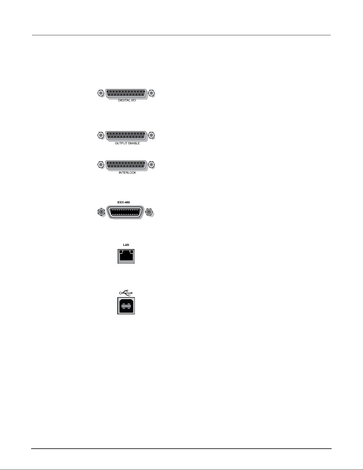
3. Digital I/O
2601B, 2602B, 2611B, 2612B, 2635B, 2636B
Female DB-25 connector. Use a cable equipped with a
male DB-25 connector (L-com part number
CSMN25MF-5).
Pins provided: Fourteen digital input or output pins,
seven GND pins, and three +5 V pins.
The 2601B, 2602B, and 2604B have an output enable
pin. The 2611B, 2612B, 2635B, and 2636B have an
interlock pin.
2604B
Pins provided: One output enable pin, seven GND pins,
and three +5 V pins. The digital input and output pins are
not available on the 2604B.
2614B, 2634B
Pins provided: One interlock pin, seven GND pins, and
three +5 V pins. The digital input and output pins are not
available on the 2614B and 2634B.
4. IEEE-488
Connector for IEEE-488 (GPIB) operation. Use a
shielded cable such as the Keithley Instruments
Model 7007-1.
5. LAN
RJ-45 connector for a local area network (LAN). The
LAN interface supports Auto-MDIX, so you can use
either a CAT-5e crossover cable or a normal CAT-5e
straight-through cable.
6. USB port
Use the USB-2.0 receptacle (Type B) on the rear panel
to connect the instrument to a computer. You can use
this connection to send commands to the instrument.
Page 27

Series 2600B System SourceMeter® instrument User's Manual Section 3: Instrument description
2600BS-900-01 Rev. A / August 2021 3-11
7. Ground
2601B, 2602B, 2604B, 2611B, 2612B, 2614B
Ground terminal for connection output HI or LO to
chassis ground.
Ground screw for connections to chassis ground.
2635B
Triaxial connector on ground module.
Screw terminal connector on ground module.
2634B, 2636B
Triaxial connector on ground module.
Screw terminal connector on ground module.
8. TSP-Link
Expansion interface that allows a 2600B and other
TSP-enabled instruments to trigger and communicate
with each other. Use a category 5e or higher LAN
crossover cable.
The TSP-Link is not available on the 2604B, 2614B,
and 2634B.
9. Power module
Contains the ac line receptacle and power line fuse. The
instrument can operate on line voltages of 100 V ac to
240 V ac at line frequencies of 50 Hz or 60 Hz.
10. RS-232
Female DB-9 connector. For RS-232 operation, use a
straight-through (not null modem) DB-9 shielded cable to
connect to the computer.
Page 28

Section 3: Instrument description Series 2600B System SourceMeter® instrument User's Manual
3-12 2600BS-900-01 Rev. A / August 2021
Menu overview
The following topics describe how to work with the front-panel menus.
Menu navigation
To navigate through the menus and submenus, the 2600B must not be in edit mode (the EDIT
indicator is not illuminated).
Selecting menu items
To navigate the Main and Configuration menus, use the front-panel keys as follows:
• Press either CURSOR arrow key to highlight an option.
• Rotate the navigation wheel (clockwise or counterclockwise) to highlight an option.
• Press the ENTER key (or the navigation wheel) to select an option.
• Use the EXIT (LOCAL) key to cancel changes or to return to the previous menu or display.
For quick menu navigation, turn the navigation wheel to highlight an option and then press the
navigation wheel to select the highlighted option.
Menu trees
You can configure instrument operation through the menus that are accessed from the front panel.
Main menu
The main menu structure is summarized in the following figure and table. For other menu items, see
Configuration menus (on page 3-15).
Page 29

Series 2600B System SourceMeter® instrument User's Manual Section 3: Instrument description
2600BS-900-01 Rev. A / August 2021 3-13
Figure 10: Main menu tree
1 Mutually exclusive
2 TSP-Link is not available on the 2604B, 2614B, and 2634B
3 DIGOUT is not available on the 2604B, 2614B, and 2634B
The following table contains descriptions of the main menu options and cross-references to
related information.
To access a menu option, press the MENU key, turn the navigation wheel to move the cursor to
select an item, and press the navigation wheel.
Page 30
Section 3: Instrument description Series 2600B System SourceMeter® instrument User's Manual
3-14 2600BS-900-01 Rev. A / August 2021
Menu selection
Description
For more information, see:
SCRIPT
Saves and recalls user scripts
Series 2600B Reference Manual,
“Manage scripts”
- LOAD
Loads scripts into nonvolatile memory
- SAVE
Saves scripts
SETUP
Saves and recalls user and factory setup options
Series 2600B Reference Manual, “Saved
setups”
- SAVE
Saves user setup options
- RECALL
Recalls user setup options
- POWERON
Sets the configuration used during startup
GPIB
Configures the GPIB interface options
Series 2600B Reference Manual, “Remote
communications interfaces”
- ADDRESS
Configures the address for the GPIB interface
- ENABLE
Enables and disables the GPIB interface
LAN
Configures the local area network (LAN)
Series 2600B Reference Manual, “LAN
communications”
- STATUS
Displays LAN connection status
- CONFIG
Configures the LAN IP address and gateway
- APPLY_SETTINGS
Applies changes made using the CONFIG menu
- RESET
Restores the default settings
- ENABLE
Enables and disables the LAN interface
RS232
Controls the options for the RS-232 interface
Series 2600B Reference Manual, “Remote
communications interfaces”
- BAUD
Sets the baud rate
- BITS
Configures the number of bits
- PARITY
Sets the parity
- FLOW-CTRL
Configures the flow control
- ENABLE
Enables and disables the RS-232 interface
TSPLINK
Configure the instrument in a TSP-Link® network
Series 2600B Reference Manual,
“TSP-Link system expansion interface”
- NODE
Selects the instrument node identifier
- RESET
Resets the TSP-Link network
UPGRADE
Upgrades the firmware from a USB flash drive
Upgrading the firmware (on page 5-4)
DISPLAY
Accesses display functions
Front-panel tests (on page 5-3)
- TEST
Runs the display test
See Numeric entry method in Setting a
value (on page 3-19)
- NUMPAD
Enables and disables the numeric keypad
DIGOUT
Controls digital outputs
Series 2600B Reference Manual, “Digital
I/O”
- DIG-IO-OUTPUT
Selects the digital I/O values
- WRITE-PROTECT
Write-protects specific digital I/O lines
- LEGACY-MODE
Sets digital I/O to work like an older
SourceMeter instrument
BEEPER
Controls the key beeps
Beeper (on page 3-21)
- ENABLE
Enables the key beeps
- DISABLE
Disables the key beeps
LINE-FREQ
Configures the line frequency
Line frequency configuration (on page 2-4)
- 50Hz
Set the line frequency to 50 Hz
- 60Hz
Set the line frequency to 60 Hz
- AUTO
Enables automatic line-frequency detection during
start up
SYSTEM-INFO
Displays the system information
System information (on page 2-4)
- FIRMWARE
Displays the version of firmware installed
- SERIAL#
Displays the serial number of the unit
- CAL
Displays the last calibration date
- MEMORY-USAGE
Displays memory usage in percentage
RESET-PASSWORD
Resets the system password
Series 2600B Reference Manual,
“Password management”
Page 31

Series 2600B System SourceMeter® instrument User's Manual Section 3: Instrument description
2600BS-900-01 Rev. A / August 2021 3-15
Configuration menus
The configuration menu structure is summarized in the following figures. More detailed information
follows the figures. For directions on navigating the menu, see Menu navigation (on page 3-12). For
other menu items, see Main menu (on page 3-12).
Figure 11: CONFIG menu tree CHANNEL menu (models with two SMUs)
1 Select a value
2 Enter a value
3 2634B and 2636B only
Press the EXIT key to return to a previous menu.
Page 32

Section 3: Instrument description Series 2600B System SourceMeter® instrument User's Manual
3-16 2600BS-900-01 Rev. A / August 2021
Figure 12: CONFIG menu tree COMMON menu (models with two SMUs)
1 Enter a value
2 Replace X with A for SMU Channel A (such as in CHANA-BUF) or a B for SMU Channel B
(such as in CHANB-BUF)
Press the EXIT key to return to a previous menu.
Page 33

Series 2600B System SourceMeter® instrument User's Manual Section 3: Instrument description
2600BS-900-01 Rev. A / August 2021 3-17
Figure 13: CONFIG menu tree (models with a single SMU)
1 Select a value
2 Enter a value
3 Model 2635B only
Press the EXIT key to return to a previous menu.
Page 34

Section 3: Instrument description Series 2600B System SourceMeter® instrument User's Manual
3-18 2600BS-900-01 Rev. A / August 2021
The following table contains descriptions of the configuration menus and cross-references to related
information. To select a menu for single SMU instruments, press the CONFIG key and then the
front-panel key associated with the menu (see the description column in the following table). For
two-SMU instruments, press the CONFIG key, select the appropriate channel (CHANNEL-A,
CHANNEL-B) and then the front-panel key associated with the menu. To select TRIG and STORE
menus on two-SMU instruments, press the CONFIG key and then select COMMON instead of
selecting a channel.
To access, press the
CONFIG key and then:
Options
For more information, see:
SRC
V-source sense and low range;
I-source low range; and
high capacitance mode
Series 2600B Reference Manual, “Range”
“Basic source-measure procedure”
MEAS
V and I-measure range,
V-measure sense, low range, and
autozero
Series 2600B Reference Manual, “Range”
“Basic source-measure procedure”
LIMIT
V-source and I-source compliance
limits
Limits (on page 4-2)
SPEED
Measurement speed (NPLC)
Series 2600B Reference Manual, “Speed”
REL
Set relative values
Series 2600B Reference Manual, “Relative
offset”
FILTER
Control digital filter
Series 2600B Reference Manual, “Filters”
OUTPUT ON/OFF
Set off-state, control digital I/O
Output-off states (on page 4-31)
STORE
Set buffer count and destination
Series 2600B Reference Manual,
“Source-measure concepts”
TRIG
Set trigger in, count, interval,
and delay
Series 2600B Reference Manual,
“Triggering”
Page 35

Series 2600B System SourceMeter® instrument User's Manual Section 3: Instrument description
2600BS-900-01 Rev. A / August 2021 3-19
Setting values
Through the front panel, you can adjust a value using either the Navigation wheel method or
Numeric entry method (using the keypad).
Setting a value
To set a value using the navigation wheel method:
1. Use the CURSOR arrow keys (or turn the navigation wheel) to move the cursor to the digit that
needs to be changed.
2. Press the navigation wheel or the ENTER key to enter edit mode. The EDIT indicator is
illuminated.
3. Rotate the navigation wheel to set the appropriate value.
4. Press the ENTER key to select the value or press the EXIT (LOCAL) key to cancel the change.
5. To return to the main menu, press the EXIT (LOCAL) key.
To set a value using the numeric entry method:
1. If the keypad is disabled, press the MENU key, then select DISPLAY > NUMPAD > ENABLE.
2. Use the CURSOR arrow keys (or turn the navigation wheel) to move the cursor to the value that
needs to be changed.
3. Press the navigation wheel or the ENTER key to enter edit mode. The EDIT indicator is
illuminated.
4. Press any of the number keys (0-9, +/-, 0000) (see 2. SMU setup, performance control, special
operation, and numbers (on page 3-3)). The cursor moves to the next digit on the right.
5. Repeat the above steps as required to set the values.
6. Press the ENTER key to select the value or press the EXIT (LOCAL) key to cancel the change.
7. To return to the main menu, press the EXIT (LOCAL) key.
To set a value to zero, press the 0000 numeric entry key. To toggle the polarity of a value, press the
+/– numeric entry key.
Page 36

Section 3: Instrument description Series 2600B System SourceMeter® instrument User's Manual
3-20 2600BS-900-01 Rev. A / August 2021
Setting source and compliance values
When the 2600B is in the edit mode (EDIT indicator is on), the editing controls are used to set source
and compliance values. Note that when you edit the source value, source autoranging is turned off
and remains off until you turn it on again.
To cancel source editing, press the EXIT (LOCAL) key.
To edit the source value:
1. Press the SRC key. The cursor flashes in the source value field.
2. Use the CURSOR keys (or turn the navigation wheel) to move the cursor to the digit that needs to
be changed.
3. Press the navigation wheel or the ENTER key to edit the source value. The EDIT indicator is
illuminated.
4. Change the source value (see Setting a value (on page 3-19)).
The +/- key toggles the polarity. The 0000 key sets the value to 0.
5. When finished, press the ENTER key (the EDIT indicator is not illuminated).
To edit compliance limit values:
1. Press the LIMIT key.
2. Select the type of compliance (CURRENT, VOLTAGE, or POWER).
3. Press the navigation wheel or the ENTER key to enter edit mode. The EDIT indicator
is illuminated.
4. Change the compliance value (see Setting a value (on page 3-19)).
5. When finished, press the ENTER key (the EDIT indicator is not illuminated).
The up and down range keys change the format of the limit value.
Page 37

Series 2600B System SourceMeter® instrument User's Manual Section 3: Instrument description
2600BS-900-01 Rev. A / August 2021 3-21
Beeper
The 2600B includes a beeper. When it is enabled, a beep indicates one of the following
actions occurred:
• A front-panel key was pressed: A short beep, similar to a key click, is issued.
• The navigation wheel was turned or pressed: A short beep is issued.
• The output source was changed: A longer beep is issued when you select the OUTPUT
ON/OFF control (turn the output on or off).
To turn the beeper on or off from the front panel:
1. Press the MENU key, and then select BEEPER.
2. Select one of the following:
▪ ENABLE
▪ DISABLE
To turn the beeper on or off from the TSP command interface:
Set the beeper.enable attribute. For example, to enable the beeper, send:
beeper.enable = 1
Displayed error and status messages
During operation and programming, front-panel messages may be briefly displayed. Typical
messages are either status or error notifications (refer to the Error summary list for a complete list of
these messages and their meanings).
Status and error messages are held in a queue. For information about retrieving messages from
queues, refer to Queues. For information about error messages, refer to the Troubleshooting guide.
Page 38

Section 3: Instrument description Series 2600B System SourceMeter® instrument User's Manual
3-22 2600BS-900-01 Rev. A / August 2021
Display operations
This section describes methods for using the display and determining what is displayed.
Display mode
Use the DISPLAY key to scroll through the various display modes shown in the figure below. Refer to
Display operations (on page 3-22) for more information about the display.
For the 2602B, 2604B, 2612B, 2614B, 2634B, and 2636B only, press the DISPLAY key more than
once to cycle through the dual channel and single channel display modes. This applies to CHANNEL
A (SMU A) and CHANNEL B (SMU B).
The Models 2601B, 2611B, and 2635B have a single channel (SMU A).
Figure 14: Display modes
Page 39

Series 2600B System SourceMeter® instrument User's Manual Section 3: Instrument description
2600BS-900-01 Rev. A / August 2021 3-23
Display functions and attributes
The display functions and attributes for the front panel are described in this section. The following
table lists each display function and attribute (in alphabetical order) and cross references it to the
section topic where the function or attribute is explained.
The TSP command reference provides additional information about the display functions
and attributes.
Cross-referencing functions and attributes to section topics
Function or attribute*
Section topic
display.clear()
Clearing the display (on page 3-25)
display.getannunciators()
Indicators (on page 3-31)
display.getcursor()
Cursor position (on page 3-26)
display.getlastkey()
Capturing key-press codes
display.gettext()
Displaying text messages (on page 3-27)
display.inputvalue()
Parameter value prompting (on page 3-30)
display.loadmenu.add()
display.loadmenu.catalog()
display.loadmenu.delete()
Load test menu (on page 3-32)
display.locallockout
LOCAL lockout (on page 3-32)
display.menu()
Menu (on page 3-29)
display.numpad
Setting a value (on page 3-19)
display.prompt()
Parameter value prompting (on page 3-30)
display.screen
Display screen (on page 3-24)
display.sendkey()
Sending key codes
display.setcursor()
Cursor position (on page 3-26)
display.settext()
Displaying text messages (on page 3-27)
display.smuX.digits
Display resolution (on page 3-24)
display.smuX.limit.func
Limit functions (on page 3-24)
display.smuX.measure.func
Measurement functions (on page 3-24)
display.trigger.clear()
display.trigger.wait()
Display trigger wait and clear (on page 3-25)
display.waitkey()
Capturing key-press codes
* smuX can be smua for channel A or smub for channel B
Page 40

Section 3: Instrument description Series 2600B System SourceMeter® instrument User's Manual
3-24 2600BS-900-01 Rev. A / August 2021
Display features
You can set the front-panel display to display the units of measure, number of digits, and customized
text messages for your applications.
Display screen
The front panel displays source-measure values and readings or user-defined messages. The display
screen options include:
• Source-measure, compliance screens: Display SMU source-measure readings and
compliance values.
• User screen: Displays user-defined messages and prompts.
Configure the type of source-measure and compliance displayed by setting the display.screen
attribute. The following programming example illustrates how to display source-measure and
compliance values, and measure readings for SMU A:
display.screen = display.SMUA
Measurement functions
With a source-measure screen selected, the measured reading can be displayed as volts, amperes,
ohms, or watts. Configure the type of measured reading displayed by setting the
display.smuX.measure.func attribute. The following programming example illustrates how to set
SMU A to display ohms measurements:
display.smua.measure.func = display.MEASURE_OHMS
Limit functions
On single SMU display screens, the displayed limit value can either reflect the primary limit value
(current or voltage limit, as applicable), or as the power limit value (that displays the power limit).
Configure the type of limit function displayed by setting the display.smuX.limit.func attribute.
The following programming example illustrates how to set SMU A to display its power limit setting:
display.smua.limit.func = display.LIMIT_P
Display resolution
Display resolution for measured readings can be set to 4½, 5½, or 6½. Configure the type of
resolution displayed by setting the display.smuX.digits attribute. The following programming
example illustrates how to set SMU A for 5½ digit resolution for measured readings:
display.smua.digits = display.DIGITS_5_5
Page 41

Series 2600B System SourceMeter® instrument User's Manual Section 3: Instrument description
2600BS-900-01 Rev. A / August 2021 3-25
Display trigger wait and clear
To set the instrument to wait for the front-panel TRIG key to be pressed, send the
display.trigger.wait() function. To clear the trigger event detector, send the
display.trigger.clear() function.
Display messages
You can define text messages that can be displayed on the front panel of the instrument. Most of the
display functions and attributes that are associated with display messaging automatically select the
user screen. The attribute for the display screen is explained in Display screen (on page 3-24).
For example, while a test is running, the following message can be displayed on the 2600B
front panel:
Test in Process
Do Not Disturb
The top line of the display can accommodate up to 20 characters (including spaces). The bottom line
can display up to 32 characters (including spaces) at a time.
The display functions display.clear(), display.setcursor(), and display.settext()
are overlapped, nonblocking commands. The script does not wait for one of these commands
to complete.
These nonblocking functions do not immediately update the display. For performance considerations,
they write to a background file and update the display as soon as processing time
becomes available.
The reset functions reset() and smua.reset() do not change the defined display message or its
configuration. The reset functions set the display mode to the previous source-measure
display mode. To show the user-defined message again, press DISPLAY until the User screen
is displayed.
Clearing the display
When sending a command to display a message, a previously defined user message is not cleared.
The new message starts at the end of the old message on that line. It is good practice to routinely
clear the display before defining a new message.
After displaying an input prompt, the message is displayed even after the operator performs the
prescribed action. The clear() function must be sent to clear the display. To clear both lines of the
display, but not affect any of the indicators, send the following function:
display.clear()
Page 42

Section 3: Instrument description Series 2600B System SourceMeter® instrument User's Manual
3-26 2600BS-900-01 Rev. A / August 2021
Cursor position
When displaying a message, the cursor position determines where the message starts. On power-up,
the cursor is positioned at row 1, column 1 (see the following figure). At this cursor position, a
user-defined message is displayed on the top row (row 1).
Top line text does not wrap to the bottom line of the display automatically. Any text that does not fit on
the current line is truncated. If the text is truncated, the cursor is left at the end of the line.
Figure 15: Row and column format for display messaging
1 Columns for Row 1
2 Columns for Row 2
3 Row 1
4 Row 2
X Display character
The function to set cursor position has the following options:
display.setcursor(row, column)
display.setcursor(row, column, style)
Where:
row
1 or 2
column
1 to 20 (row 1)
1 to 32 (row 2)
style
0 (invisible)
1 (blink)
When set to 0, the cursor is not visible. When set to 1, a display character blinks to indicate the
cursor position.
The display.getcursor() function returns the present cursor position. You can use it in
these ways:
row, column, style = display.getcursor()
row, column = display.getcursor()
row = display.getcursor()
Page 43

Series 2600B System SourceMeter® instrument User's Manual Section 3: Instrument description
2600BS-900-01 Rev. A / August 2021 3-27
The following programming example illustrates how to position the cursor on row 2, column 1, and
then read the cursor position:
display.setcursor(2, 1)
row, column = display.getcursor()
print(row, column)
Output:
2.00000e+00 1.00000e+00
Displaying text messages
To define and display a message, use the display.settext(text) function, where text is the
text string to be displayed. The message starts at the present cursor position. The following
programming example illustrates how to display Test in Process on the top line, and Do Not
Disturb on the bottom line:
display.clear()
display.setcursor(1, 1, 0)
display.settext("Test in Process")
display.setcursor(2, 6, 0)
display.settext("Do Not Disturb")
Character codes
The following special codes can be embedded in the text string to configure and customize
the message:
• $N: Starts text on the next line (newline). If the cursor is already on line 2, text is ignored after the
‘$N’ is received.
• $R: Sets text to Normal.
• $B: Sets text to Blink.
• $D: Sets text to Dim intensity.
• $F: Set text to background blink.
• $$: Escape sequence to display a single “$”.
In addition to displaying alphanumeric characters, you can display other special characters. Refer to
the Series 2600B Reference Manual, “Display character codes,” for a list of special characters and
their corresponding codes.
The following programming example illustrates how to display the Greek symbol omega (Ω):
display.clear()
c = string.char(18)
display.settext(c)
Page 44

Section 3: Instrument description Series 2600B System SourceMeter® instrument User's Manual
3-28 2600BS-900-01 Rev. A / August 2021
The following programming example illustrates how to use the $N and $B character codes to display
the message Test in Process on the top line and the blinking message Do Not Disturb on the
bottom line:
display.clear()
display.settext("Test in Process $N$BDo Not Disturb")
The following programming example illustrates how to use the $$ character code to display the
message You owe me $8 on the top line:
display.clear()
display.setcursor(1, 1)
display.settext("You owe me $$8")
If the extra $ character is not included, the $8 is interpreted as an undefined character code and is
ignored. The message You owe me is displayed.
Be careful when embedding character codes in the text string. It is easy to forget that the character
following the $ is part of the code. For example, if you want to display Hello on the top line and
Nate on the bottom line, send the following command:
display.settext("Hello$Nate")
The above command displays Hello on the top line and ate on the bottom line. The correct syntax
for the command is as follows:
display.settext("Hello$NNate")
Returning a text message
The display.gettext() function returns the displayed message (text) and has the
following options:
text = display.gettext()
text = display.gettext(embellished)
text = display.gettext(embellished, row)
text = display.gettext(embellished, row, columnStart)
text = display.gettext(embellished, row, columnStart, columnEnd)
Where:
embellished
Returns text as a simple character string (false) or includes character codes (true)
row
The row to read text from (1 or 2); if not included, text from both rows is read
columnStart
Starting column for reading text
columnEnd
Ending column for reading text
Page 45

Series 2600B System SourceMeter® instrument User's Manual Section 3: Instrument description
2600BS-900-01 Rev. A / August 2021 3-29
Sending the command without the row parameter returns both lines of the display. The $N character
code is included to show where the top line ends and the bottom line begins. The $N character code
is returned even if embellished is set to false.
With embellished set to true, all other character codes that were used in the creation of each
message line are returned with the message. With embellished set to false, only the message
is returned.
Sending the command without the columnStart parameter defaults to column 1. Sending the
command without the columnEnd argument defaults to the last column (column 20 for row 1,
column 32 for row 2).
Input prompting
You can use display messaging with front panel controls to make a user script interactive. In an
interactive script, input prompts are displayed so that the operator can perform a prescribed action
using the front panel controls. While displaying an input prompt, the test pauses and waits for the
operator to perform the prescribed action.
Menu
You can present a user-defined menu on the display. The menu consists of the menu name on the
top line and a selectable list of menu items on the bottom line. To define a menu, use the
display.menu(menu, items) function, where:
menu
The name of the menu; use a string of up to 20 characters (including spaces)
items
A string is made up of one or more menu items; each item must be separated by white space
When the display.menu() function is sent, script execution waits for the operator to select one of
the menu items. Rotate the navigation wheel to place the blinking cursor on a menu item. Items that
do not fit in the display area are displayed by rotating the navigation wheel to the right. With the
cursor on the menu item, press the navigation wheel (or the ENTER key) to select it.
Pressing the EXIT (LOCAL) key does not abort the script while the menu is displayed, but it returns
nil. The script can be aborted by calling the exit() function when nil is returned.
The following programming example illustrates how to present the operator with the choice of two
menu items: Test1 or Test2. If Test1 is selected, the message Running Test1 is displayed. If
Test2 is selected, the message Running Test2 is displayed.
display.clear()
menu = display.menu("Sample Menu", "Test1 Test2")
if menu == "Test1" then
display.settext("Running Test1")
else
display.settext("Running Test2")
end
Page 46

Section 3: Instrument description Series 2600B System SourceMeter® instrument User's Manual
3-30 2600BS-900-01 Rev. A / August 2021
Parameter value prompting
You can use the display.inputvalue() and display.prompt() functions to create an editable
input field on the user screen at the present cursor position.
The display.inputvalue() function uses the user screen at the present cursor position. Once
the command is finished, it returns the user screen to its previous state. The display.prompt()
function creates a new edit screen and does not use the user screen.
Each of these functions can be used in the following ways:
display.inputvalue(format)
display.inputvalue(format, default)
display.inputvalue(format, default, min)
display.inputvalue(format, default, min, max)
display.prompt(format, units, help)
display.prompt(format, units, help, default)
display.prompt(format, units, help, default, min)
display.prompt(format, units, help, default, min, max)
Where:
format
String that creates an editable input field on the user screen at the present cursor position
(examples: +0.00 00, +00, 0.00000E+0)
Value field:
+ = Include for positive/negative value entry; omitting the + prevents negative value entry
0 = Defines the digit positions for the value (up to six zeros (0))
Exponent field (optional):
E = include for exponent entry
+ = Include for positive/negative exponent entry; omitting the + prevents negative value entry
0 = Defines the digit positions for the exponent
default
Option to set a default value for the parameter, which is displayed when the command is sent
min
Option to specify minimum limits for the input field
▪ When NOT using the “+” sign for the value field, the minimum limit cannot
be set to less than zero
▪ When using the “+” sign, the minimum limit can be set to less than zero
(for example, -2)
max
Option to specify maximum limits for the input field
units
Text string to identify the units for the value (8 characters maximum), for example:
Units text is “V” for volts and “A” for amperes
help
Informational text string to display on the bottom line (32 characters maximum)
Both the display.inputvalue() and display.prompt() functions display the editable input
field, but the display.inputvalue() function does not include the text strings for units
and help.
After one of the above functions is executed, command execution pauses and waits for the operator
to input the source level. The program continues after the operator enters the value by pressing the
navigation wheel or the ENTER key.
Page 47

Series 2600B System SourceMeter® instrument User's Manual Section 3: Instrument description
2600BS-900-01 Rev. A / August 2021 3-31
The following programming example illustrates how to prompt the operator to enter a source voltage
value for SMU A:
display.clear()
value = display.prompt("0.00", "V", "Enter source voltage")
display.screen = display.SMUA
smua.source.levelv = value
The script pauses after displaying the prompt message and waits for the operator to enter the voltage
level. The display then toggles to the source-measure display for SMU A and sets the source level
to value.
If the operator presses EXIT(LOCAL) instead of entering a source value, value is set to nil.
The second line of the above code can be replaced using the other input field function:
value = display.inputvalue("0.00")
The only difference is that the display prompt does not include the “V” units designator and the Enter
source value message.
Indicators
To determine which front-panel display indicators are turned on, use the
display.getannunciators() function. For example, send the following commands.
annun = display.getannunciators()
print(annun)
The 16-bit binary equivalent of the returned value is a bitmap. Each bit corresponds to an indicator. If
the bit is set to 1, the indicator is turned on. If the bit is set to 0, the indicator is turned off.
The following table identifies the bit position for each indicator. The table also includes the weighted
value of each bit. The returned value is the sum of all the weighted values for the bits that are set.
Bit identification for indicators
Bit
B16
B15
B14
B13
B12
B11
B10
B9
Annunciator
REL
REAR
SRQ
LSTN
TALK
REM
ERR
EDIT
Weighted value*
32768
16384
8192
4096
2048
1024
512
256
Binary value
0/1
0/1
0/1
0/1
0/1
0/1
0/1
0/1
Bit
B8
B7
B6
B5
B4
B3
B2
B1
Annunciator
SMPL
STAR
TRIG
ARM
AUTO
4W
MATH
FILT
Weighted value*
128
64
32
16 8 4 2 1
Binary value
0/1
0/1
0/1
0/1
0/1
0/1
0/1
0/1
* The weighted values are for bits that are set to 1. Bits set to 0 have no value.
Not all the indicators shown in above table may be used by the 2600B.
Page 48

Section 3: Instrument description Series 2600B System SourceMeter® instrument User's Manual
3-32 2600BS-900-01 Rev. A / August 2021
For example, assume the returned bitmap value is 34061. The binary equivalent of this value is as
follows:
1000010100001101
For the above binary number, the following bits are set to 1: 16, 11, 9, 4, 3, and 1. Using the table, the
following indicators are on: REL, REM, EDIT, AUTO, 4W, and FILT.
Local lockout
You can use the front-panel EXIT (LOCAL) key to cancel remote operation and return control to the
front panel. However, this key can be locked out to prevent a test from being interrupted. When
locked, this key becomes a NO-OP (no operation). Configure the following attribute to lock or unlock
the EXIT (LOCAL) key:
display.locallockout = lockout
Where lockout is set to one of the following values:
0 or display.UNLOCK
1 or display.LOCK
For example, to lock out the EXIT (LOCAL) key:
display.locallockout = display.LOCK
Load test menu
The LOAD TEST menu lists tests (USER, FACTORY, and SCRIPTS) that can be run from the front
panel.
Factory tests are preloaded and saved in nonvolatile memory at the factory. They are available in the
FACTORY TESTS submenu.
If you load named scripts into the runtime environment, they can be selected from the front-panel
SCRIPTS menu.
User tests
User tests can be added to or deleted from the USER TESTS submenu.
Page 49

Series 2600B System SourceMeter® instrument User's Manual Section 3: Instrument description
2600BS-900-01 Rev. A / August 2021 3-33
Adding USER TESTS menu entries
You can use the following function in either of two ways to add an entry into the USER TESTS menu:
display.loadmenu.add(displayname, code)
display.loadmenu.add(displayname, code, memory)
Where:
displayname
The name string that is added to the USER TESTS menu.
code
The code that is run from the USER TESTS menu when the RUN button is pressed.
It can include any valid Lua code.
memory
A value that specifies if the code and displayname parameters are saved in
nonvolatile memory. Set to one of the following values:
0 or display.DONT_SAVE
1 or display.SAVE (this is the default setting)
Scripts, functions, and variables that are used in the code are not saved when display.SAVE is
used. Functions and variables need to be saved with the script. If the script is not saved in nonvolatile
memory, it is lost when the 2600B is turned off. See Example 1 below.
Example 1:
Assume a script with a function named DUT1 has been loaded into the 2600B, and the script has not
been saved in nonvolatile memory.
Now assume you want to add a test named Test to the USER TESTS menu. You want the test to
run the function named DUT1 and sound the beeper. The following programming example illustrates
how to add Test to the menu, define the code, and then save displayname and code in
nonvolatile memory:
display.loadmenu.add("Test", "DUT1() beeper.beep(2, 500)", display.SAVE)
When Test is run from the front-panel USER TESTS menu, the function named DUT1 executes and
the beeper beeps for two seconds.
Now assume you turn the 2600B power off and then on again. Because the script was not saved in
nonvolatile memory, the function named DUT1 is lost. When Test is again run from the front panel,
the beeper beeps, but DUT1 does not execute because it is no longer in the runtime environment.
Example 2:
The following command adds an entry called Part1 to the front-panel USER TESTS submenu for the
code testpart([[Part1]], 5.0) and saves it in nonvolatile memory:
display.loadmenu.add("Part1", "testpart([[Part1]], 5.0)", display.SAVE)
Page 50
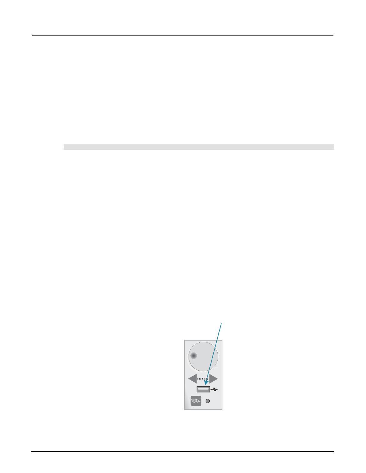
Section 3: Instrument description Series 2600B System SourceMeter® instrument User's Manual
3-34 2600BS-900-01 Rev. A / August 2021
Deleting USER TESTS menu entries
You can use the following function to delete an entry from the front-panel USER TESTS menu:
display.loadmenu.delete(displayname)
Where:
displayname
Name to delete from the menu.
The following programming example removes the entry named Part1 from the front-panel USER
TESTS menu:
display.loadmenu.delete("Part1")
Running a test from the front panel
To run a user, factory, or script test from the front panel:
1. Press the LOAD key to display the LOAD TEST menu.
2. Select the USER, FACTORY, or SCRIPTS menu item.
3. Position the blinking cursor on the test to be run and press ENTER or the navigation wheel.
4. Press the RUN key to run the test.
Connecting the USB flash drive
The 2600B supports flash drives that comply with USB 2.0 standards and USB 1.0 and 1.1 standards.
You can save data to the USB flash drive from the front panel, or you can create a script to save data
to the USB flash drive.
To connect the USB flash drive, plug the USB flash drive into the USB port on the front panel of the
instrument, shown in the figure below.
Figure 16: USB port
Page 51

Series 2600B System SourceMeter® instrument User's Manual Section 3: Instrument description
2600BS-900-01 Rev. A / August 2021 3-35
Using the web interface
If you are connected to the 2600B using LAN communications, you can use an internet browser to
connect to the instrument through the 2600B web interface.
The LXI web interface allows you to change settings and control your instrument through the web
interface. The web interface includes:
• A virtual front panel that you can use to control the instrument.
• TSB Embedded, a script management tool that can also be used to send individual commands to
the instrument.
• The instrument status, model, serial number, firmware revision, and the last LXI message.
• An ID button to help you locate the instrument.
• Ability to download data from specific reading buffers into a .csv file.
• Administrative options, LAN information, and LXI information.
The web interface resides in the firmware of the instrument. Changes you make through the web
interface are immediately made in the instrument.
You can also upgrade the instrument from the web interface. Refer to Upgrading the firmware (on
page 5-4) for instructions.
To set up LAN connections, refer to Series 2600B Reference Manual, “LAN communications.”
How to access the web interface
You can access the web interface by entering the IP address of the instrument in the address line of
an internet browser.
To get the IP address of the instrument:
1. From the front panel, press the MENU key.
2. Select LAN > STATUS.
3. Use the navigation wheel to select IP-ADDRESS.
4. Press the ENTER key to view the active setting.
5. Press the EXIT (LOCAL) key once to return to the STATUS menu.
To find the IP address of the 2600B from a computer, use the LXI Discovery Tool, a utility that is
available from the Resources tab of the LXI Consortium website (lxistandard.org).
Page 52

Section 3: Instrument description Series 2600B System SourceMeter® instrument User's Manual
3-36 2600BS-900-01 Rev. A / August 2021
To access the web interface:
1. Open a web browser on the host computer.
2. Enter the IP address of the instrument in the web browser address box. For example, if the
instrument IP address is 192.168.1.101, enter 192.168.1.101 in the browser address box.
3. Press Enter on the computer keyboard to open the web interface of the instrument.
If the web interface does not open in the browser, see LAN troubleshooting suggestions.
Web interface Welcome page
The Welcome page provides information about the instrument. It includes:
• The instrument model number, manufacturer, firmware revision number, and instrument serial
number.
• LXI information.
• LAN connection information.
• The TCP Raw Socket number and Telnet Port number.
• Instrument address strings.
• Calibration dates.
• The ID button, which helps you find the instrument if you have multiple instruments.
Figure 17: Web interface Welcome page
Page 53

Series 2600B System SourceMeter® instrument User's Manual Section 3: Instrument description
2600BS-900-01 Rev. A / August 2021 3-37
Use the ID button to identify the instrument
If you have a bank of instruments, you can select the ID button to determine which instrument you are
communicating with.
The ID button is below the menu on every page of the web interface.
To identify the instrument:
1. Select ID. The button turns green and the message "LAN Status Indicator" is displayed on the
front panel of the instrument.
2. Select ID again to return the button to its original color and return the front-panel display to its
previous state.
Change the IP configuration through the web interface
You can change the LAN settings through the web interface on the instrument. The LAN settings you
can change include the IP address, subnet mask, gateway, and DNS address.
If you change the IP address through the web interface, the web interface tries to redirect to the IP
address that is configured in the instrument. In some cases, this may fail. This generally happens if
you switch from an IP address assignment that uses a static address to an IP address assignment
that uses a DHCP server. If this happens, you need to revert to either using the front panel to set the
IP address or use an automatic discovery tool to determine the new IP address.
You can use the host name instead of the IP address to connect to the instrument.
You can also change the IP configuration through the front panel or with TSP commands. Refer to
“LAN communications” section of the Series 2600B Reference Manual for information on setting the
configuration through the front panel. Refer to the lan.config.* command descriptions in the
“TSP command reference” section of the Series 2600B Reference Manual for information on using
TSP commands to configure the LAN settings.
To change the IP configuration using the web interface:
1. Access the web interface as described in How to access the web interface (on page 3-35).
2. Select IP Configuration.
3. Select Modify. The Modify IP Configuration page is displayed.
4. Change the values.
5. Click Submit. The instrument reconfigures its settings, which may take a few moments.
You may lose your connection with the web interface after clicking Submit. This is normal. If this
occurs, find the correct IP address and reopen the web interface of the instrument to continue.
Page 54

Section 3: Instrument description Series 2600B System SourceMeter® instrument User's Manual
3-38 2600BS-900-01 Rev. A / August 2021
Set the instrument password
You can change the instrument password from the web interface. The instrument password is used
for access to the instrument from any remote interface. When password usage is enabled by the
localnode.passwordmode command, you must supply a password to change the configuration or
to control an instrument a remote command interface.
When a password is set for the web interface and localnode.passwordmode is set to an option
that requires a password, you cannot make changes using the web interface options Virtual Front
Panel, Flash Upgrade, and TSB Embedded.
The default password is "" (no password).
You cannot retrieve a lost password from any command interface. You can reset the password from
the front panel. Select MENU, then RESET-PASSWORD.
For information on the TSP commands, refer to localnode.passwordmode in the Series 2600B
Reference Manual.
To change the password:
1. Select Set Password.
2. In the Current Password box, enter the presently used password.
3. In the New Password and Confirm New Password boxes, enter the new password.
4. Select Submit.
Using the virtual front panel
The Virtual Front Panel page allows you to control the instrument from a computer as if you were
using the front panel of the instrument. You can operate the instrument using a mouse to
select options.
The virtual front panel operates the same way as the actual front panel except that you cannot switch
the instrument on or off with the power switch.
For information on the front-panel controls, see Instrument description (on page 3-1).
To use the virtual front panel, you can use any standard web browser.
You can access the Virtual Front Panel from multiple interfaces and each interface can make
changes. You may need to refresh the browser to see changes made by another interface.
Page 55

Series 2600B System SourceMeter® instrument User's Manual Section 3: Instrument description
2600BS-900-01 Rev. A / August 2021 3-39
Figure 18: Virtual front panel
View buffer data using the web interface
You can view the data in the reading buffers on the Reading Buffers page of the Virtual Front Panel
web page.
To view the data, at the top of the virtual front panel, select Reading Buffers. On the Reading Buffers
page, select a reading buffer from the Reading Buffer list. The data is displayed in the table.
Initially, the reading number and reading measurement values are displayed. You can display
additional data using the filters to the right of the table. You can choose:
• Measurement: Include or exclude measurement information.
• Source: Include or exclude source information.
• Other: Include or exclude status, status detail, and timestamp information. For detail on the
Status value, refer to “Buffer status” in the Series 2600B Reference Manual.
An example of the Reading Buffers page with the measurement and source functions displayed is
shown in the following figure.
Page 56

Section 3: Instrument description Series 2600B System SourceMeter® instrument User's Manual
3-40 2600BS-900-01 Rev. A / August 2021
Figure 19: Web interface Reading Buffers page
Download reading buffer data using the web interface
You can download reading buffer data to a .csv file from the Reading Buffers page of the web
interface.
The data shown in the table on the Reading Buffers page is downloaded.
To download buffer data:
1. From the web interface, select Virtual Front Panel.
2. Select Reading Buffers.
3. From the Reading Buffer list, select the reading buffer that contains the data you want
to download.
4. From the options on the right, filter the reading buffer list to display the data you want to
download.
5. Select Save. The file is downloaded to your computer.
6. Follow the instructions for your browser to open the file. Typically, the file opens in
Microsoft Excel.
Page 57

Series 2600B System SourceMeter® instrument User's Manual Section 3: Instrument description
2600BS-900-01 Rev. A / August 2021 3-41
Using TSB Embedded
TSB Embedded is a script management tool that is available through the web interface of the
instrument. You can use TSB Embedded to create, modify, and save test scripts, and to send
individual commands. TSB Embedded provides some of the features of Test Script Builder (TSB).
TSB is a software tool that simplifies building test scripts for Keithley Instruments that are enabled to
use Test Script Processor (TSP®).
For more information on using TSB Embedded for script management, refer to “Working with TSB
Embedded” in the Series 2600B Reference Manual.
Send individual commands using the web interface
To send individual commands using the web interface:
1. Select TSB Embedded.
2. In the Console box, enter the command.
3. Select Enter to send the command to the instrument. The command is displayed in the Output
box. If there is a response to the command, it is displayed after the command.
4. To clear the Output box, right-click and select Clear.
Review events in the LXI Event Log
The Log option opens the LXI Event Log. The event log records all LXI events that the instrument
generates and receives. The log includes the following information:
• The EventID column, which shows the identifier of the event that generated the event message.
• The PTP Timestamp column, which displays the seconds and fractional (nano) seconds when the
event occurred.
• The Data column, which displays the text of the event message.
To clear the event log and update the information on the screen, select Refresh.
Logging LAN trigger events in the event log
You can use the event log to record all LXI triggers generated and received by the 2600B. You can
view the event log using any command interface or the embedded web interface. The following figure
shows the view of the LXI event log from the Log option in the embedded web interface.
Page 58

Section 3: Instrument description Series 2600B System SourceMeter® instrument User's Manual
3-42 2600BS-900-01 Rev. A / August 2021
Figure 20: LXI Event Log
The timestamp, event identifier, IP address, and the domain name identify the incoming and outgoing
LXI trigger packets. The following table provides detailed descriptions for the columns in the
event log.
Event log descriptions
Column title
Description
Example
Receive Time
Displays the date and time that the LAN trigger
occurred in UTC, 24-hour time
11:46:44.000 11 Mar 2020
Event ID
Identifies the lan.trigger[N] that generates an
event
LAN0 = lan.trigger[1]
LAN1 = lan.trigger[2]
LAN2 = lan.trigger[3]
LAN3 = lan.trigger[4]
LAN4 = lan.trigger[5]
LAN5 = lan.trigger[6]
LAN6 = lan.trigger[7]
LAN7 = lan.trigger[8]
From
Displays the IP address for the device that
generates the LAN trigger
localhost
192.168.5.20
Timestamp
A timestamp that identifies the time the event
occurred; the timestamp uses the following:
▪ PTP timestamp
▪ Seconds
▪ Fractional seconds; the 2600B does not
support the IEEE Std 1588 standard; the
values in this field are always 0 (zero)
HWDetect
Identifies a valid LXI trigger packet
LXI
Page 59

Series 2600B System SourceMeter® instrument User's Manual Section 3: Instrument description
2600BS-900-01 Rev. A / August 2021 3-43
Event log descriptions
Column title
Description
Example
Sequence
Each instrument maintains independent
sequence counters:
▪ One for each combination of UDP multicast
network interface and UDP multicast
destination port
▪ One for each TCP connection
Domain
Displays the LXI domain number; the default value
is 0 (zero)
0
Flags
Contain data about the LXI trigger packet;
values are:
▪ 1 - Error
▪ 2 - Retransmission
▪ 4 - Hardware
▪ 8 - Acknowledgments
▪ 16 - Stateless bit
16
Data
The values for this are always 0 (zero)
Accessing the event log from the command interface
You can access the event log from any remote command interface. The event log must be enabled
before LXI trigger events can be viewed. To enable the event log, send:
eventlog.enable = 1
To view the event log from a remote interface, send:
print(eventlog.all())
This command outputs one or more strings similar to the following:
14:14:02.000 17 Jun 2019, LAN0, 10.80.64.191, LXI, 0, 1560780842, not available, 0,
0x10,0x00
Page 60

Section 3: Instrument description Series 2600B System SourceMeter® instrument User's Manual
3-44 2600BS-900-01 Rev. A / August 2021
The string displays the same information as the web interface. Commas separate the fields. The
fields output in the following order:
• Received time (UTC time)
• Event ID
• From (Sender)
• HWDetect / version
• Domain
• Sequence number
• Timestamp (PTP time)
• Epoch (from 1588)
• Flags
• Data
See the table in Logging LAN trigger events in the event log (on page 3-41) for detailed descriptions.
To generate log traffic, send the code:
local id = 1
lan.trigger[id].ipaddress = lan.status.ipaddress
lan.trigger[id].connect()
for domain = 1, 255 do
print(domain)
lan.lxidomain = domain
lan.trigger[id].assert()
delay(1)
end
Help
The help page in the web interface provides basic help for the web interface, a glossary of terms, and
a link to licenses for the virtual front panel, firmware upgrade tool, and TSB Embedded.
Page 61

In this section:
Basic operation ........................................................................ 4-1
Source-measure capabilities .................................................... 4-1
Limits ........................................................................................ 4-2
Sink operation .......................................................................... 4-5
DUT test connections ............................................................... 4-6
Front-panel source-measure procedure ................................. 4-28
Sense mode selection ............................................................ 4-30
Output-off modes ................................................................... 4-31
Basic operation
For the Models 2611B, 2612B, 2614B, 2634B, 2635B, and 2636B, hazardous voltages may be
present on all output and guard terminals. To prevent electrical shock that could cause injury
or death, never make or break connections to the 2600B while the instrument is powered on.
Turn off the equipment from the front panel or disconnect the main power cord from the rear
of the 2600B before handling cables. Putting the equipment into standby does not guarantee
that the outputs are powered off if a hardware or software fault occurs.
Source-measure capabilities
From the front panel, you can configure the instrument to perform the following
source-measure operations:
• Source voltage: Measure and display current, voltage, resistance, or power
• Source current: Measure and display voltage, current, resistance, or power
• Measure resistance: Display resistance calculated from voltage and current components of
measurement (can optionally specify source voltage or source current value)
• Measure power: Display power calculated from voltage and current components of
measurement (can optionally specify source voltage or source current value)
• Measure only (V or I): Display voltage or current measurement
Section 4
Operation
Page 62

Section 4: Operation Series 2600B System SourceMeter® instrument User's Manual
4-2 2600BS-900-01 Rev. A / August 2021
Voltage and current
The following table lists the source and measure limits for the voltage and current functions. The full
range of operation is explained in “Operating boundaries” in the Series 2600B Reference Manual.
Source-measure capabilities
2601B, 2602B, 2604B
2611B, 2612B, 2614B
2634B, 2635B, 2636B
Range
Source
Measure
Range
Source
Measure
Range
Source
Measure
100 mV
1 V
6 V
40 V
100 nA
1 µA
10 µA
100 µA
1 mA
10 mA
100 mA
1 A
3 A
10 A1
±101 mV
±1.01 V
±6.06 V
±40.4 V
±101 nA
±1.01 µA
±10.1 µA
±101 µA
±1.01 mA
±10.1 mA
±101 mA
±1.01 A
±3.03 A
±10.1 A
±102 mV
±1.02 V
±6.12 V
±40.8 V
±102 nA
±1.02 µA
±10.2 µA
±102 µA
±1.02 mA
±10.2 mA
±102 mA
±1.02 A
±3.06 A
±10 A
200 mV
2 V
20 V
200 V2
100 nA
1 µA
10 µA
100 µA
1 mA
10 mA
100 mA
1 A
1.5 A
10 A3
±202 mV
±2.02 V
±20.2 V
±202 V
±101 nA
±1.01 µA
±10.1 µA
±101 µA
±1.01 mA
±10.1 mA
±101 mA
±1.01 A
±1.515 A
±10.1 A
±204 mV
±2.04 V
±20.4 V
±204 V
±102 nA
±1.02 µA
±10.2 µA
±102 µA
±1.02 mA
±10.2 mA
±102 mA
±1.02 A
±1.53 A
±10.2 A
200 mV
2 V
20 V
200 V4
100 pA
1 nA
10 nA
100 nA
1 µA
10 µA
100 µA
1 mA
10 mA
100 mA
1 A
1.5 A
10 A5
±202 mV
±2.02 V
±20.2 V
±202 V
N/A
±1.01 nA
±10.1 nA
±101 nA
±1.01 µA
±10.1 µA
±101 µA
±1.01 mA
±10.1 mA
±101 mA
±1.01 A
±1.515 A
±10.1 A
±204 mV
±2.04 V
±20.4 V
±204 V
±102 pA
±1.02 nA
±10.2 nA
±102 nA
±1.02 µA
±10.2 µA
±102 µA
±1.02 mA
±10.2 mA
±102 mA
±1.02 A
±1.53 A
±10 A
Maximum power = 40.4 W per
channel
Maximum power = 30.603 W per
channel
Maximum power = 30.603 W per
channel
1
10 A range available only in
pulse mode.
2
200 V source range available only when
interlock is enabled.
3
10 A range available only in pulse mode.
4
200 V source range available only when
interlock is enabled.
5
10 A range available only in pulse mode.
Limits
When sourcing voltage, you can set the instrument to limit current or power. Conversely, when
sourcing current, you can set the instrument to limit voltage or power. In steady-state conditions, the
instrument output does not exceed the limit. The maximum limit is the same as the maximum values
listed in the following table.
The limit circuit limits in either polarity regardless of the polarity of the source or limit value. The
accuracy of the limit opposite in polarity from the source is diminished unless the instrument is in sink
operation (on page 4-5). The maximum limits are based on source range.
Page 63

Series 2600B System SourceMeter® instrument User's Manual Section 4: Operation
2600BS-900-01 Rev. A / August 2021 4-3
The limit operation of the instrument changes dependent on the source mode (current or voltage),
load, and the configured limits (current, voltage, and power). It is important to distinguish both the
current and voltage limits from the power limit. As the names imply, the current limit restricts the
current for sourced voltage, and the voltage limit restricts the voltage for a sourced current. The
power limit, however, restricts power by lowering the present limit in effect (voltage or current) as
needed to restrict the SMU from exceeding the specified power limit. For additional details on using
limits, including load considerations when specifying both a current (or a voltage) limit and a power
limit, see “Operating boundaries” in the Series 2600B Reference Manual.
For additional information on limits, refer to “Limit principles” in the Series 2600B Reference Manual.
The only exception to the limit not being exceeded is the voltage limit when operating as a current
source. To avoid excessive and potentially destructive currents from flowing, the voltage limit
sources or sinks up to 102 mA for current source ranges on or below 100 mA. For ranges 1 A and
above, the maximum current allowed is the current source setting.
Maximum limits
2601B, 2602B, 2604B
2611B, 2612B, 2614B
2634B, 2635B, 2636B
Source
range
Maximum
limit
Source
range
Maximum
limit
Source
range
Maximum
limit
100 mV
1 V
6 V
40 V
3 A
3 A
3 A
1 A
200 mV
2 V
20 V
200 V
1.5 A
1.5 A
1.5 A
100 mA
200 mV
2 V
20 V
200 V
1.5 A
1.5 A
1.5 A
100 mA
100 nA
1 µA
10 µA
100 µA
1 mA
10 mA
100 mA
1 A
3 A
40 V
40 V
40 V
40 V
40 V
40 V
40 V
40 V
6 V
100 nA
1 µA
10 µA
100 µA
1 mA
10 mA
100 mA
1 A
1.5 A
200 V
200 V
200 V
200 V
200 V
200 V
200 V
20 V
20 V
1 nA
10 nA
100 nA
1 µA
10 µA
100 µA
1 mA
10 mA
100 mA
1 A
1.5 A
200 V
200 V
200 V
200 V
200 V
200 V
200 V
200 V
200 V
20 V
20 V
Page 64

Section 4: Operation Series 2600B System SourceMeter® instrument User's Manual
4-4 2600BS-900-01 Rev. A / August 2021
Setting the limit from the front panel
To set the limit for a single-channel instrument (2601B, 2611B, or 2635B) or the single-channel
display mode of a two-channel instrument (2602B, 2604B, 2612B, 2614B, 2634B, or 2636B):
1. Press the LIMIT key. Pressing the LIMIT key while in limit edit mode toggles the display between
the complementary function limit and the power limit display.
2. Press the navigation wheel and set the limit to the new value.
3. Press the ENTER key or the navigation wheel to complete editing.
4. Press the EXIT (LOCAL) key to return to the main display.
To set the limit for a two-channel instrument (2602B, 2604B, 2612B, 2614B, 2634B, or 2636B) in
dual-channel mode:
1. Press the LIMIT key.
2. Select CURRENT, VOLTAGE, or POWER as needed. Press the ENTER key or the navigation
wheel.
3. Press the navigation wheel and set the limit to the new value.
4. Press the ENTER key or the navigation wheel to complete editing.
5. Press the EXIT (LOCAL) key to return to the main display.
Setting the limit from a remote interface
The table below summarizes basic commands to program a limit. For a more complete description of
these commands, refer to the “TSP command reference” section of the Series 2600B
Reference Manual.
Limit commands
Command*
Description
smuX.source.limiti = limit
Set current limit.
smuX.source.limitv = limit
Set voltage limit.
smuX.source.limitp = limit
Set power limit.
compliance = smuX.source.compliance
Test if in limit (true = in limit; false = not in limit).
* smuX can be smua for channel A or smub for channel B
To set the limit, send the command with the limit value as the parameter. The following programming
example illustrates how to set the current, voltage, and power limit to 50 mA, 4 V, and 1 W,
respectively:
smua.source.limiti = 50e-3
smua.source.limitv = 4
smua.source.limitp = 1
Page 65

Series 2600B System SourceMeter® instrument User's Manual Section 4: Operation
2600BS-900-01 Rev. A / August 2021 4-5
The following programming example illustrates how to print the limit state:
print(smua.source.compliance)
A returned value of true indicates one of these things:
• If the instrument is configured as a current source, the voltage limit has been reached
• If the instrument is configured as a voltage source, the current limit has been reached
Sink operation
Carefully consider and configure the appropriate output-off state, source function, and
compliance limits before connecting the 2600B to a device that can deliver energy (for
example, other voltage sources, batteries, capacitors, solar cells, or other 2600B
instruments). Configure recommended instrument settings before making connections to the
device. Failure to consider the output-off state, source, and compliance limits may result in
damage to the instrument or to the device under test (DUT).
When operating as a sink (voltage and current have opposite polarity), the instrument is dissipating
power rather than sourcing it. An external source (for example, a battery) or an energy storage device
(for example, a capacitor) can force operation into the sink region. For example, if a 12 V battery is
connected to the voltage source (HI to battery +) that is programmed for +10 V, sink operation occurs
in the second quadrant (source +V and measure −I).
When operating as a sink, limit inaccuracies are introduced. Enabling sink mode reduces the source
limit inaccuracy seen when operating in quadrants II and IV. Quadrants I and III show this source
limit inaccuracy.
The sink operating limits are shown in “Continuous power operating boundaries” in the Series 2600B
Reference Manual.
When using the current source as a sink, always set the voltage compliance to a level that is
higher than the external voltage level. Failure to do so could result in excessive current flow
into the instrument and incorrect measurements. See Limits (on page 4-2) for details about
compliance limits.
Page 66

Section 4: Operation Series 2600B System SourceMeter® instrument User's Manual
4-6 2600BS-900-01 Rev. A / August 2021
Setting the sink mode using the front panel
To enable or disable the sink mode from the front panel:
1. Press the CONFIG key and then the SRC key.
2. Select V-SOURCE.
3. Select SINK-MODE.
4. Select ENABLE or DISABLE.
5. Press the ENTER key. Sink mode is enabled or disabled, as applicable.
6. Press the EXIT (LOCAL) key twice to return to the main display.
Setting the sink mode from a remote interface
To enable sink mode from the remote interface, send:
smua.source.sink = smua.ENABLE
To disable sink mode, send:
smua.source.sink = smua.DISABLE
DUT test connections
Hazardous voltages may be present in the test system. To prevent injury or death, remove
power from the instrument or test system and discharge any energy storage components (for
example, capacitors or cables) before changing any connections that might allow contact
with an uninsulated conductor.
On some sensitive or easily damaged devices under test (DUTs), the instrument power-up and
power-down sequence can apply transient signals to the DUT that may affect or damage it. When
testing this type of DUT, do not make final connections to it until the instrument has completed its
power-up sequence and is in a known operating state. When testing this type of DUT, disconnect it
from the instrument before turning the instrument off.
To prevent any human contact with a live conductor, connections to the DUT must be fully insulated
and the final connections to the DUT must only use safety-rated safety-jack-socket connectors that
do not allow bodily contact.
Page 67

Series 2600B System SourceMeter® instrument User's Manual Section 4: Operation
2600BS-900-01 Rev. A / August 2021 4-7
The fundamental source-measure configurations for the 2600B are shown in the following figures.
When sourcing voltage, you can measure current or voltage, as shown in the following figure.
Figure 21: Fundamental source-measure configurations: Source V
A
Current meter
+ − Voltage source
V
Voltage meter
When sourcing current, you can measure voltage or current, as shown in the following figure.
Figure 22: Fundamental source-measure configuration: Source I
A
Current meter
↑
Current source
V
Voltage meter
Refer to “Circuit configurations” in the Series 2600B Reference Manual for detailed information.
Page 68

Section 4: Operation Series 2600B System SourceMeter® instrument User's Manual
4-8 2600BS-900-01 Rev. A / August 2021
Input/output connectors
The 2600B uses screw terminal connectors or triaxial connectors for input and output connections to
devices under test (DUTs). The 2601B, 2602B, 2604B, 2611B, 2612B, and 2614B use screw terminal
connectors. The 2634B, 2635B, and 2636B use triaxial connectors.
A screw terminal connector can be removed from the rear panel by loosening the two captive
retaining screws and pulling it off the rear panel. Each screw in the terminal connector cable
assembly (used with the SMU connector) can accommodate from 24 AWG (0.2 mm2) to 12 AWG
(2.5 mm2) conductors.
Basic connection sequence:
1. With the output off and the connector uninstalled from the 2600B rear panel, make the wire
connections from a connector to the DUT.
2. Reinstall the connector onto the rear panel.
3. If using a screw terminal connector, tighten the two captive screws.
Hazardous voltages may be present on the output and guard terminals. To prevent electrical
shock that could cause injury or death, never make or break connections to the 2600B while
the output is on. Power off the equipment from the front panel or disconnect the main power
cord from the rear of a 2600B before handling cables connected to the outputs. Putting the
equipment into standby does not guarantee the outputs are not powered if a hardware or
software fault occurs.
Maximum floating (common mode) voltage for a SMU is 250 V. Exceeding this level could
damage the instrument and create a shock hazard. See Floating a SMU (on page 4-26) for
details on floating the SMUs.
The input/output connectors of the 2600B are rated for connection to circuits rated
Measurement Category I only, with transients rated less than 1500 V
PEAK
. Do not connect the
2600B terminals to CAT II, CAT III, or CAT IV circuits. Connections of the input/output
connectors to circuits higher than CAT I can cause damage to the equipment or expose the
operator to hazardous voltages.
To prevent electric shock and/or damage to the 2600B, when connecting to a source with a
greater current capability than the 2600B, a user-supplied fuse, rated at no more than 20 A
SLO-BLO, should be installed in-line with the 2600B input/output connectors.
Page 69

Series 2600B System SourceMeter® instrument User's Manual Section 4: Operation
2600BS-900-01 Rev. A / August 2021 4-9
Figure 23: Input/output connectors
Input/output LO and chassis ground
As shown in the following figures, SMU input/output LOs are available at the rear panel terminal
blocks. Input/output LOs are not connected between channels and are electrically isolated from
chassis ground.
The chassis should never be used as a ground point for signal connections. High frequencies (more
than 1 MHz) present on the chassis of the 2600B may result in higher noise. The chassis should only
be used as a safety shield. Use the chassis screw for connections to the chassis of the 2600B. For
2634B, 2635B, and 2636B, connect to ground on the ground module, not to the chassis screw.
Page 70

Section 4: Operation Series 2600B System SourceMeter® instrument User's Manual
4-10 2600BS-900-01 Rev. A / August 2021
Figure 24: Models 2602B, 2604B, 2612B, and 2614B input/output LO and chassis ground
terminals (2601B and 2611B similar)
1 Captive screw. Each terminal block uses two captive screws to secure it to the rear panel.
Figure 25: Models 2634B and 2636B input/output and chassis ground terminals (Model 2635B
similar)
For the 2601B, 2602B, 2604B, 2611B, 2612B, and 2614B, there is a low-noise chassis ground
banana jack that can be used as a common signal ground point for input and output LOs. This
low-noise signal ground banana jack is connected to the chassis through a frequency variable
resistor (FVR).
Page 71

Series 2600B System SourceMeter® instrument User's Manual Section 4: Operation
2600BS-900-01 Rev. A / August 2021 4-11
The FVR, shown in the following figure, isolates the SMUs from high frequencies that may be present
on the chassis of the 2600B. As frequencies on the chassis increase, the resistance of the FVR
increases to dampen its effects. For dc to 60 Hz, the FVR is a virtual short (0 ohms).
Figure 26: Models 2601B, 2602B, 2604B, 2611B, 2612B, and 2614B low-noise chassis ground
banana jack and chassis screw
1 Low-noise chassis ground banana jack
2 A local signal ground, which is the ow-noise chassis ground banana jack
3 Frequency variable resistor (FVR)
4 Metal chassis of the 2600B
5 Chassis screw terminal; connected to the metal chassis of the 2600B
Figure 27: Model 2634B and 2636B (Model 2635B similar)
Page 72

Section 4: Operation Series 2600B System SourceMeter® instrument User's Manual
4-12 2600BS-900-01 Rev. A / August 2021
When connecting to 2611B, 2612B, 2614B, 2634B, 2635B, and 2636B SMU outputs using
cables that are not rated for voltages above 42 V, such as the 2600-ALG-2, you must disable
the high voltage output by using the INTERLOCK function as defined in Interlock (on page
4-23). Leaving the high voltage enabled while not properly insulating the external connections
to the instrument poses a shock hazard which could cause serious injury to the user. It is
also recommended that the LO connection terminal not be allowed to float by connecting it to
signal ground or another known signal reference.
2-wire local sensing connections
You can use 2-wire local sensing measurements, shown in the following figure, for the following
source-measure conditions:
• Sourcing and measuring current.
• Sourcing and measuring voltage in high impedance (more than 1 kΩ) test circuits.
When using 2-wire local sensing connections, make sure to properly configure the 2600B Sense
mode selection (on page 4-30).
Figure 28: Two-wire resistance connections
4-wire remote sensing connections
When sourcing and measuring voltage in a low-impedance test circuit, there can be errors associated
with lead resistance. Voltage source and measure accuracy are optimized by using 4-wire remote
sense connections. When sourcing voltage, 4-wire remote sensing ensures that the programmed
voltage is delivered to the DUT. When measuring voltage, only the voltage drop across the DUT
is measured.
By default, the 2600B instruments are configured to use 2-wire (local) voltage sensing. If you choose
to enable 4-wire (remote) voltage sensing, it is critical that you establish and maintain the proper
Kelvin connections between the corresponding force and sense leads to ensure the proper operation
of the instrument and to make accurate voltage measurements. Sense HI must be connected to
Force HI, and Sense LO must be connected to Force LO.
Page 73

Series 2600B System SourceMeter® instrument User's Manual Section 4: Operation
2600BS-900-01 Rev. A / August 2021 4-13
When sourcing voltage with remote sense, the instrument relies on the voltage detected with the
sense lines to provide the proper closed-loop control of its output voltage and to properly limit the
voltage across the device-under-test. If a sense line becomes disconnected from its corresponding
force line, an erroneous voltage is sensed. The output voltage may be adjusted to a level that is
radically different than the programmed voltage level (possibly to hazardous levels, depending on the
model). In addition, the voltage across the device may exceed the programmed source limit voltage,
possibly causing damage to the device or test fixture.
In both cases, the voltage is not measured correctly if a sense lead becomes disconnected from its
corresponding force lead.
Even with the overvoltage protection set to the lowest value (2 V), never touch anything
connected to the terminals of the 2600B when the instrument is on. Always assume that a
hazardous voltage (greater than 30 V
RMS
) is present when the instrument is on. To prevent
damage to the device under test or external circuitry, do not set the voltage source to levels
that exceed the value that is set for overvoltage protection.
For the 2601B, 2602B, 2611B, 2612B, 2635B, and 2636B, you can use contact check to verify that
the sense leads are connected before enabling remote sensing or before turning on the output. Refer
to Contact check measurements (on page 4-14).
Use 4-wire remote sensing for the following source-measure conditions:
• Sourcing or measuring voltage in low impedance (<1 kΩ) test circuits.
• Enforcing voltage compliance limit directly at the DUT.
When using 4-wire local sensing connections, make sure to properly configure the Sense mode
selection (on page 4-30).
Figure 29: Four-wire connections (remote sensing)
Page 74

Section 4: Operation Series 2600B System SourceMeter® instrument User's Manual
4-14 2600BS-900-01 Rev. A / August 2021
Contact check connections
The contact check function prevents measurement errors due to excessive resistance in the source or
sense leads. See Contact check measurements (on page 4-14) for operation.
Contact check requires both source and sense connections. Refer to 4-wire remote sensing
connections (on page 4-12) for the connection scheme.
Contact check measurements
The Models 2604B, 2614B, and 2634B do not perform contact check measurements.
The contact check function prevents measurements that may be in error due to excessive resistance
in the force or sense leads when making remotely sensed (Kelvin) measurements. Potential sources
for this resistance include poor contact at the device under test (DUT), failing relay contacts on a
switching card, and wires that are too long or thin. To use contact check, the current limit must be at
least 1 mA (this allows enough current to flow when performing the test), and the source-measure unit
(SMU) must not be in High-Z output-off mode.
The contact check function also detects an open circuit that may occur when a four-point probe is
misplaced or misaligned. This relationship is shown schematically in the figure below, where RC is the
resistance of the mechanical contact at the DUT, and RS is the series resistance of relays and cables.
Figure 30: Contact check measurements
When the source is off, smuX.source.offmode is set to smuX.OUTPUT_ZERO, and the effective
current limit is less than 1 mA, contact check operations result in error code 5066,
source.offlimiti too low for contact check. In the zero off mode,
Page 75

Series 2600B System SourceMeter® instrument User's Manual Section 4: Operation
2600BS-900-01 Rev. A / August 2021 4-15
smuX.source.offlimiti is ignored and the effective current limit depends on what the channel is
sourcing when it is turned off. If the channel is sourcing:
• Voltage: The current limit is determined by smuX.source.limiti.
• Current: The current limit is determined by the greater of smuX.source.leveli or 10 percent
of smuX.source.rangei.
Contact check commands
The following table summarizes the contact check commands. For a more complete description of
these commands, refer to the “TSP command reference” section of the Series 2600B
Reference Manual.
Basic contact check commands
Command
Description
flag = smuX.contact.check()
Determine if contact resistance is lower than threshold.
rhi, rlo = smuX.contact.r()
Measure the aggregate contact resistance.
smuX.contact.speed = speedSetting
Set speedSetting to one of the following:
▪ 0 or smuX.CONTACT_FAST
▪ 1 or smuX.CONTACT_MEDIUM
▪ 2 or smuX.CONTACT_SLOW
smuX.contact.threshold = rvalue
Set resistance threshold for the contact check function.
Contact check programming example
The following programming example illustrates the setup and command sequence for a typical
contact check measurement. These commands set the contact check speed to fast and the threshold
to 100 Ω. Then, a contact check measurement against the threshold is made. If it fails, a more
accurate contact check measurement is made, and the test is aborted. Otherwise, the output is
turned on, and the test continues.
-- Restore defaults.
smua.reset()
-- Set contact check speed to fast.
smua.contact.speed = smua.CONTACT_FAST
-- Set the contact check threshold to 100 ohms.
smua.contact.threshold = 100
-- Check contacts against threshold.
if not smua.contact.check() then
-- Set speed to slow.
smua.contact.speed = smua.CONTACT_SLOW
-- Get aggregate resistance readings.
rhi, rlo = smua.contact.r()
-- Return contact resistances to the host.
print(rhi, rlo)
-- Terminate execution.
exit()
end
-- Turn output on and continue.
smua.source.output = smua.OUTPUT_ON
Page 76

Section 4: Operation Series 2600B System SourceMeter® instrument User's Manual
4-16 2600BS-900-01 Rev. A / August 2021
Guarding and shielding
You can optimize source-measure performance and safety with the effective use of guarding and
shielding (noise and safety shields).
Safety shield
A safety shield must be used whenever hazardous voltages (>30 V
RMS
, 42 V
PEAK
) will be
present in the test circuit. To prevent electrical shock that could cause injury or death, never
use the 2600B in a test circuit that may contain hazardous voltages without a properly
installed and configured safety shield.
The safety shield can be metallic or nonconductive and must completely surround the device under
test (DUT) test circuit. A metal safety shield must be connected to a known protective earth (safety
ground). See Test fixtures (on page 4-24) for important safety information on the use of a metal or a
nonconductive enclosure.
Safety shielding and hazardous voltages
For the 2601B, 2602B, and 2604B, the maximum output voltage for a channel is 40 V, which is
considered a nonhazardous level. However, using two 2601B, 2602B, or 2604B voltage sources in a
series configuration or floating a SMU (on page 4-26) can cause test circuit voltage to exceed 42 V.
For example, the source-measure units (SMUs) of two 2601B, 2602B, or 2604B instruments can be
connected in series to apply 80 V to a device under test (DUT) (see the following figure). See “TSP
advanced features” in the Series 2600B Reference Manual for information on using multiple System
SourceMeter® instruments.
Use #18 AWG wire or larger for connections to safety earth ground and chassis.
Page 77

Series 2600B System SourceMeter® instrument User's Manual Section 4: Operation
2600BS-900-01 Rev. A / August 2021 4-17
Figure 31: Safety shield for hazardous voltage combining two 2601B, 2602B, or 2604B
channels
1 Chassis
2 Chassis screw
3 Device under test (DUT)
4 Protective earth (safety ground)
5 Equivalent schematic
6 Metal safety shield
For the 2611B, 2612B, 2614B, 2634B, 2635B, and 2636B, the maximum output voltage for a channel
is 220 V, which is considered hazardous and requires a safety shield. The following figures illustrate
test connections for these models.
Use #18 AWG wire or larger for connections to safety earth ground and chassis.
Page 78

Section 4: Operation Series 2600B System SourceMeter® instrument User's Manual
4-18 2600BS-900-01 Rev. A / August 2021
Figure 32: Model 2611B, 2612B, or 2614B safety shield for hazardous voltage test circuit
connections
1 Chassis
2 Chassis screw
3 Device under test (DUT)
4 Protective earth (safety ground)
5 Equivalent schematic
6 Metal safety shield
Page 79

Series 2600B System SourceMeter® instrument User's Manual Section 4: Operation
2600BS-900-01 Rev. A / August 2021 4-19
Figure 33: Model 2634B, 2635B, or 2636B safety shield for hazardous voltage test circuit
connections
1 Protective earth (safety ground)
2 Equivalent schematic
3 Metal safety shield
4 Device under test (DUT)
Page 80

Section 4: Operation Series 2600B System SourceMeter® instrument User's Manual
4-20 2600BS-900-01 Rev. A / August 2021
Guarding
A driven guard is always enabled and provides a buffered voltage that is at the same level as the
input/output HI voltage. The purpose of guarding is to eliminate the effects of leakage current (and
capacitance) that can exist between HI and LO. Without guarding, leakage and capacitance in the
external high-impedance test circuit could be high enough to adversely affect the performance of
the 600B.
Guarding is recommended when test circuit impedance is >1 GΩ.
See “Guard” in the Series 2600B Reference Manual for details on the principles of guarding.
The guard shield can be the shield of a coaxial cable or an insulated foil that surrounds
the conductor.
Figure 34: Connections for guarding
1 Guard shield
2 Metal guard shield
3 Device under test (DUT)
Page 81

Series 2600B System SourceMeter® instrument User's Manual Section 4: Operation
2600BS-900-01 Rev. A / August 2021 4-21
Noise shield
Use a noise shield (see following figure) to prevent unwanted signals from being introduced into the
test circuit. Low-level signals may benefit from effective shielding. The metal noise shield surrounds
the test circuit and should be connected to LO, as shown.
Connect the enclosure of all metal test fixtures to protective earth (safety ground). See your
specific test fixture for information. Nonconductive test fixtures must be rated to double the
maximum capability of the test equipment in the system.
Connections to LO on the 2600B are not necessarily at 0 V. Hazardous voltages could exist
between LO and chassis ground. Make sure that high-voltage precautions are taken
throughout the test system. Alternatively, limit hazardous levels by adding external
protection to limit the voltage between LO and chassis. Failure to make sure high-voltage
precautions are used throughout the test system or a failure to limit hazardous levels could
result in severe personal injury or death from electric shock.
Figure 35: Models 2602B, 2604B, 2612B, and 2614B noise shield
1 Noise shield connected to LO
2 Noise shield
3 Device under test (DUT)
Page 82

Section 4: Operation Series 2600B System SourceMeter® instrument User's Manual
4-22 2600BS-900-01 Rev. A / August 2021
Using shielding and guarding together
The following figures show connections for a test system that uses a noise shield, a safety shield, and
guarding. The guard shields are connected to the driven guard (labeled G or GUARD, depending on
your model) of the SMU. The noise shield is connected to LO. The safety shield is connected to the
chassis and to protective earth (safety ground).
Connect the enclosure of all metal test fixtures to protective earth (safety ground). See your
specific test fixture for information. Nonconductive test fixtures must be rated to double the
maximum capability of the test equipment in the system.
Figure 36: Connections for noise shield, safety shield, and guarding
1 Test circuit
2 Metal guard shield
3 Metal noise shield
4 Metal safety shield
5 Protective earth (safety ground)
6 Low-noise chassis ground banana jack
7 Chassis screw
8 Chassis
Page 83

Series 2600B System SourceMeter® instrument User's Manual Section 4: Operation
2600BS-900-01 Rev. A / August 2021 4-23
Interlock
The interlock is available on the 2611B, 2612B, 2614B, 2634B, 2635B, and 2636B only.
The digital I/O port provides the interlock line for use with a test fixture switch. When properly used,
the output of the instrument turns off when the lid of the test fixture is opened. See “DUT test
connections (on page 4-6)” in the Series 2600B User's Manual for important safety information when
using a test fixture. Follow standard safety and electrical practices by verifying the correct operation of
all components related to system safety, including the interlock.
The interlock circuit must be positively activated in order for the high voltage output to be
enabled. The interlock helps facilitate safe operation of the equipment in a test system.
Bypassing the interlock could expose the operator to hazardous voltages that could result in
personal injury or death.
Interlock operation
When on the 200 V source range, the output of the 2611B, 2612B, 2614B, 2634B, 2635B, and 2636B
can only be turned on when the interlock line is driven high through a switch to +5 V (as shown). If the
lid of the test fixture opens, the switch opens, and the interlock line goes low, turning the output of the
instrument off. The output is not automatically turned on when the interlock line is set high. The output
cannot be turned back on until the interlock line is set high.
A signal of > 3.4 V at 24 mA (at an absolute maximum of 6 V) must be externally applied to pin 23 to
ensure 200 V operation. This signal is pulled down to chassis ground with a 10 kΩ resistor. 200 V
operation is blocked when the INTERLOCK signal is < 0.4 V (an absolute minimum of −0.4 V).
Page 84

Section 4: Operation Series 2600B System SourceMeter® instrument User's Manual
4-24 2600BS-900-01 Rev. A / August 2021
Figure 37: Using 2611B, 2612B, 2614B, 2634B, 2635B, and 2636B interlock
1 INTERLOCK pin (on DIGITAL I/O or INTERLOCK connector) pin 24
2 Read by firmware
3 To output stage
4 Coil resistance
5 Chassis ground
6 Rear panel
7 Pin 23
8 Closing switch enables 200 V operation
Test fixture
You can use a test fixture to house a device or test circuit. The test fixture can be a metal or
nonconductive enclosure and is typically equipped with a lid and an interlock switch. When properly
used, the output of the 2600B turns off when the lid of the test fixture is opened. The test circuit is
mounted inside the test fixture. When hazardous voltages (>30 V
RMS
, 42 V
PEAK
) will be present, the
test fixture must meet the following safety requirements.
Page 85

Series 2600B System SourceMeter® instrument User's Manual Section 4: Operation
2600BS-900-01 Rev. A / August 2021 4-25
To provide protection from shock hazards, an enclosure should be provided that surrounds
all live parts.
Nonconductive enclosures must be constructed of materials that are suitably rated for
flammability and the voltage and temperature requirements of the test circuit. Connect the
enclosure of all metal test fixtures to protective earth (safety ground). See your specific test
fixture for information. Nonconductive test fixtures must be rated to double the maximum
capability of the test equipment in the system.
For metallic enclosures, the test fixture chassis must be properly connected to protective
earth (safety ground). A grounding wire (16 AWG or larger) must be attached securely to the
test fixture at a screw terminal designed for safety grounding. The other end of the ground
wire must be attached to a known protective earth (safety ground).
Construction material: A metal test fixture must be connected to a known protective earth (safety
ground) as described in the above warning. A nonconductive test fixture must be constructed of
materials that are suitable for flammability, voltage, and temperature conditions that may exist in the
test circuit. The construction requirements for a nonconductive enclosure are also described in the
warning above.
Test circuit isolation: With the lid closed, the test fixture must completely surround the test circuit. A
metal test fixture must be electrically isolated from the test circuit. Input and output connectors
mounted on a metal test fixture must be isolated from the test fixture. Internally, TeflonTM standoffs
are typically used to insulate the internal printed circuit board or guard plate for the test circuit from a
metal test fixture.
Interlock switch: The test fixture must have a normally-open interlock switch. The interlock switch
must be installed so that when the lid of the test fixture is opened, the switch opens, and when the lid
is closed, the switch closes.
The 2600B digital I/O port provides an output enable line or an interlock line (dependent on the model
number). When properly used with a test fixture, the output of the 2600B turns off when the lid of the
test fixture is opened. The 2601B, 2602B, and 2604B have output enable (OE) line. The 2611B,
2612B, 2614B, 2634B, 2635B, and 2636B have an interlock.
The digital I/O port of the 2601B, 2602B, or 2604B is not suitable for control of safety circuits
and should not be used to control a safety interlock. The interlock pin on the digital I/O port
for the 2611B, 2612B, 2614B, 2634B, 2635B, or 2636B can be used to control a
safety interlock.
For information on the digital I/O port, see Model Series 2600B Reference Manual, “Digital I/O.”
Page 86

Section 4: Operation Series 2600B System SourceMeter® instrument User's Manual
4-26 2600BS-900-01 Rev. A / August 2021
Floating a SMU
Using an external source in the test system may require that a 2600B source-measure unit (SMU)
float off chassis earth ground. An example of such a test system is shown below, which includes an
external voltage source. Notice that output low of the external voltage source is connected to chassis
earth ground.
For the test circuit shown below, the 2600B must float off chassis earth ground. As shown, LO of the
2600B is floating +10 V above chassis earth ground. If LO of the 2600B was instead connected to
chassis ground, the external voltage source would be shorted to the chassis ground.
Figure 38: Schematic of floating the Series 2600B
1 2600B LO not connected to chassis ground (floating)
2 Chassis
3 SMU voltage source
4 2600B chassis connected to chassis earth ground through the power cord
5 Chassis earth ground
6 Source chassis connected to chassis earth ground through the power cord
7 Output low connected to chassis
8 External source
9 DUT
The 2600B connections for the floating configuration are shown in the following figure. This figure
shows the 2602B, 2604B, 2612B, or 2614B shown. The 2601B and 2611B are similar.
Page 87

Series 2600B System SourceMeter® instrument User's Manual Section 4: Operation
2600BS-900-01 Rev. A / August 2021 4-27
Figure 39: 2601B, 2602B, 2604B, 2611B, 2612B, or 2614B SMU connections
1 External source
2 Chassis
3 Output low connected to chassis
4 DUT
5 Source chassis connected to chassis earth ground through the power cord
6 Low-noise chassis ground banana jack
7 Chassis screw
All measurement connections should be considered to be hazardous.
The maximum floating (common mode) voltage for a source-measure unit (SMU) is ±250 V.
Exceeding this level may cause damage to the instrument and create a shock hazard.
Using an external source to float a SMU could create a shock hazard in the test circuit. A
shock hazard exists whenever >42 V
PEAK
is present in the test circuit. Appropriately rated
cables or insulators must be provided for all connections to prevent access to live parts.
When >42 V is present, the test circuit must be insulated for the voltage used or surrounded
by a metal safety shield that is connected to a known protective earth (safety ground) and
chassis ground (see Safety shield (on page 4-16)).
Page 88

Section 4: Operation Series 2600B System SourceMeter® instrument User's Manual
4-28 2600BS-900-01 Rev. A / August 2021
Front-panel source-measure procedure
Use the following procedure to perform the basic source-measure operations of the 2600B SMU
using the front panel. The following procedure assumes that the 2600B is already connected to the
device under test (DUT), as explained in DUT test connections (on page 4-6).
Hazardous voltages may be present on all output and guard terminals. To prevent electrical
shock that could cause injury or death, never make or break connections to the 2600B while
the instrument is powered on. Turn off the equipment from the front panel or disconnect the
main power cord from the rear of the 2600B before handling cables. Putting the equipment
into standby does not guarantee that the outputs are powered off if a hardware or software
fault occurs.
Step 1: Select and set the source level
To select the source and edit the source value:
1. Press the SRC key as needed to select the voltage source or current source, as indicated by the
units in the source field on the display. The flashing digit (cursor) indicates which value is
presently selected for editing.
2. Move the cursor to the digit to change, then press the navigation wheel to enter the EDIT mode.
3. Use the RANGE keys to select a range that accommodates the value you want to set. For best
accuracy, use the lowest possible source range.
4. Enter the source value.
5. Press the ENTER key or the navigation wheel to complete editing.
Step 2: Set the compliance limit
To edit the compliance limit value:
1. If the instrument has two channels (2602B, 2604B, 2612B, 2614B, 2634B, or 2636B) and is in
dual-channel display mode, perform the following (steps a, b, and c). Otherwise, go to the
next step.
a. Press the CONFIG key.
b. Press the LIMIT key and then select CURRENT or VOLTAGE.
c. Press the ENTER key or the navigation wheel.
2. If the instrument has only one channel (2601B, 2611B, or 2635B), or if it is a two-channel
instrument that is in single-channel display mode, press the LIMIT key.
3. Move the cursor to the digit to change, then press the navigation wheel to enter the EDIT mode,
as indicated by the EDIT indicator.
4. Enter the limit value, then press the ENTER key or the navigation wheel to complete editing.
Page 89

Series 2600B System SourceMeter® instrument User's Manual Section 4: Operation
2600BS-900-01 Rev. A / August 2021 4-29
Step 3: Select the measurement function and range
To select measurement function and range:
1. If the instrument has two channels (2602B, 2604B, 2612B, 2614B, 2634B, or 2636B), press the
DISPLAY key to place it in single-channel-display mode (if not already). Otherwise, go to the next
step.
2. Select the measurement function by pressing the MEAS key.
3. Set the measurement range with the RANGE keys, or enable AUTO range. When setting the
range, consider the following points:
▪ When measuring the source (such as when sourcing V and measuring V), you cannot select
the measurement range using the RANGE keys. The selected source range determines the
measurement range.
▪ When not measuring the source (such as when sourcing V but measuring I), you can select
the measurement range selection manually or the instrument can set it automatically. When
using manual ranging, use the lowest possible range for best accuracy. When autorange is
enabled, the 2600B automatically goes to the most sensitive range to make
the measurement.
Step 4: Turn the output on
Turn on the output by pressing the OUTPUT ON/OFF switch. The OUTPUT indicator light turns on.
Step 5: Observe readings on the display.
Press the TRIG key if necessary to trigger the instrument to begin making readings. The readings are
on the top line, and source and limit values are on the bottom line.
Step 6: Turn the output off
When finished, turn the output off by pressing the OUTPUT ON/OFF switch. The OUTPUT indicator
light turns off.
Page 90

Section 4: Operation Series 2600B System SourceMeter® instrument User's Manual
4-30 2600BS-900-01 Rev. A / August 2021
Sense mode selection
You can set the sense mode to use 2-wire local sensing connections (on page 4-12) or 4-wire remote
sensing connections (on page 4-12). The default sense setting is 2-wire local.
Front-panel sense mode selection
To check or change the voltage sense mode from the front panel:
1. Press the CONFIG key.
2. Press the SRC or MEAS key. You can access and set the 2600B sense mode from either the
V-SOURCE or the V-MEAS menu items.
3. If you pressed the SRC key: Select V-SOURCE > SENSE-MODE, and then press the ENTER
key or the navigation wheel.
If you pressed the MEAS key: Select V-MEAS > SENSE-MODE, and then press the ENTER key
or the navigation wheel.
4. Select 2-WIRE or 4-WIRE as needed, and then press the ENTER key or the navigation wheel.
Remote interface sense mode selection
To configure the 2600B SMU for 4-wire remote sensing, send the command:
smua.sense = smua.SENSE_REMOTE
The following table summarizes the commands to select the sense mode. See the “TSP command
reference” section of the Series 2600B Reference Manual for details on using these commands.
Commands to select sense mode
Command*
Description
smuX.source.output = smuX.OUTPUT_OFF
Turn off the source-measure unit (SMU) output.
smuX.sense = smuX.SENSE_LOCAL
Select local (2-wire) sense.
smuX.sense = smuX.SENSE_REMOTE
Select remote (4-wire) sense.
* smuX can be smua for channel A or smub for channel B
Page 91

Series 2600B System SourceMeter® instrument User's Manual Section 4: Operation
2600BS-900-01 Rev. A / August 2021 4-31
Output-off modes
Carefully consider and configure the appropriate output-off state, source function, and
compliance limits before connecting the 2600B to a device that can deliver energy (for
example, other voltage sources, batteries, capacitors, solar cells, or other 2600B
instruments). Configure recommended instrument settings before making connections to the
device. Failure to consider the output-off state, source, and compliance limits may result in
damage to the instrument or to the device under test (DUT).
Turning off the 2600B output may not completely isolate the instrument from the external circuit. You
can use the output-off mode to place the 2600B in a noninteractive state during idle periods. The
available output-off modes are normal, high-impedance, and zero.
Normal output-off mode
The normal output-off mode is the default output-off mode setting. When the source-measure unit
(SMU) is in the normal output-off mode, you can select either the current or the voltage output-off
function (see Output-off function (on page 4-32)). You can also specify current and voltage output-off
limits (Output-off limits (compliance) (on page 4-33)).
When the output is turned off, the output goes to either 0 V or 0 A, depending on the selected
output-off function. Voltage is the default output-off function.
High-impedance output-off mode
For the high-impedance output-off mode (HI-Z), the output relay opens when the output is turned off.
This disconnects external circuitry from the input/output of the source-measure unit (SMU). To
prevent excessive wear on the output relay, do not use this output-off mode for tests that turn the
output off and on frequently.
Zero output-off mode
When the zero output-off mode is selected, the programmed source remains on the display, but
internally, the voltage source is selected and is set to 0 V. Measurements are made and displayed.
When the selected source is voltage, the current compliance setting remains the same as the
output-on value and compliance detection remains active.
When the selected source is current, the current compliance setting is the programmed current
source value or 10 percent full-scale of the present current range, whichever is greater.
You can use the 2600B as a current meter when it is in zero output-off mode because it outputs 0 V
but measures current.
Page 92

Section 4: Operation Series 2600B System SourceMeter® instrument User's Manual
4-32 2600BS-900-01 Rev. A / August 2021
To configure the output-off mode from the front panel:
1. Press the CONFIG key.
2. Press the OUTPUT ON/OFF control.
3. Select OFF-STATE.
4. Select MODE.
5. Select the output-off mode: HI-Z (high-impedance), NORMAL, or ZERO.
6. Press the EXIT key to return to the normal display.
To select the normal output-off mode over a remote interface:*
smua.source.offmode = smua.OUTPUT_NORMAL
To select the high-impedance output-off mode over a remote interface:*
smua.source.offmode = smua.OUTPUT_HIGH_Z
To select the zero output-off mode over a remote interface:*
smua.source.offmode = smua.OUTPUT_ZERO
* smuX can be smua for channel A or smub for channel B
Output-off function
This setting is used only when the output is turned off and the 2600B is set to the normal output-off
mode (smuX.source.offmode = smuX.OUTPUT_NORMAL).
You can set the output-off function to CURRENT or VOLTAGE through the CONFIG menu on the
front panel, or by using the smuX.source.offfunc attribute from a remote interface. VOLTAGE is
the default output-off function.
When the output is turned off and the selected output-off function is VOLTAGE
(smuX.source.offfunc = smuX.OUTPUT_DCVOLTS):
• The source-measure unit (SMU) sources 0 V.
• The current limit is set by the smuX.source.offlimiti attribute (default 1 mA).
When the output is turned off and the selected output-off function is CURRENT
(smuX.source.offfunc = smuX.OUTPUT_DCAMPS):
• The SMU sources 0 A.
• The voltage limit is set by the smuX.source.offlimitv attribute (default 40 V).
When the output-off function is set to either voltage or current, the SMU may source or sink a very
small amount of power. In most cases, this source or sink power level is insignificant.
Page 93

Series 2600B System SourceMeter® instrument User's Manual Section 4: Operation
2600BS-900-01 Rev. A / August 2021 4-33
Selecting the output-off function
This setting is used only when the output is turned off and the source-measure unit (SMU) is in
NORMAL output-off mode.
To configure the output-off function from the front panel:
1. Press the CONFIG key.
2. Press the OUTPUT ON/OFF control.
3. Select OFF-STATE and then select FUNCTION.
4. Select CURRENT or VOLTAGE.
5. Press the EXIT key to return to the normal display.
To configure the output-off function remotely:
To set 0 V output with current limit set by the smuX.source.offlimiti attribute:*
smuX.source.offfunc = smuX.OUTPUT_DCVOLTS
To set 0 A output with voltage limit set by the smuX.source.offlimitv attribute:*
smuX.source.offfunc = smuX.OUTPUT_DCAMPS
* smuX can be smua for channel A or smub for channel B
Output-off limits (compliance)
You can set output-off limits (compliance) for the current and voltage output-off functions using the
CONFIG menu on the 2600B front panel, or by setting the smuX.source.offlimitY attribute from
a remote interface. The output-off limits only apply when the output-off mode is normal.
Setting output-off limits
Setting the output-off limit for CURRENT (smuX.source.offlimiti) specifies the current limit for
the voltage source; setting the output-off limit for VOLTAGE (smuX.source.offlimitv) specifies
the voltage limit for the current source.
To configure the output-off limits from the front panel:
1. Press the CONFIG key.
2. Press the OUTPUT ON/OFF control.
3. Select OFF-STATE and then select LIMIT.
4. Select CURRENT or VOLTAGE.
5. Set the limit value and then press the ENTER key or the navigation wheel.
6. Press the EXIT key to return to the normal display.
Page 94

Section 4: Operation Series 2600B System SourceMeter® instrument User's Manual
4-34 2600BS-900-01 Rev. A / August 2021
To set the current limit in NORMAL output-off mode remotely:*
smuX.source.offlimiti = iValue
To set the voltage limit in NORMAL output-off mode remotely:*
smuX.source.offlimitv = vValue
* smuX can be smua for channel A or smub for channel B
Remote programming output-off states quick reference
The content of the following table is a quick reference of commands for programming output-off states
from a remote interface.
Output-off state programming quick reference
Command*
Description
smuX.source.offmode = smua.OUTPUT_NORMAL
Selects normal output-off mode.
smuX.source.offmode = smua.OUTPUT_HIGH_Z
Selects high-impedance output-off mode.
smuX.source.offmode = smua.OUTPUT_ZERO
Selects zero output-off mode.
smuX.source.offfunc = smua.OUTPUT_DCVOLTS
Sets 0 V output with current limit specified by
the smua.source.offlimiti attribute.
smuX.source.offfunc = smua.OUTPUT_DCAMPS
Sets 0 A output with voltage limit specified by
the smua.source.offlimitv attribute.
smuX.source.offlimiti = iValue
Sets current limit in normal output-off mode.
smuX.source.offlimitv = vValue
Sets voltage limit in normal output-off mode.
* smuX can be smua for channel A or smub for channel B
Page 95

In this section:
Introduction .............................................................................. 5-1
Line fuse replacement .............................................................. 5-1
Fuse replacement .................................................................... 5-2
Front-panel tests ...................................................................... 5-3
Upgrading the firmware ............................................................ 5-4
Displaying the serial number .................................................... 5-6
Introduction
This section describes routine maintenance of the instrument that an operator can perform.
Line fuse replacement
A fuse on the 2600B rear panel protects the power line input of the instrument. See the following
instructions to replace the fuse. You do not need to return your instrument for service if the fuse is
damaged.
Disconnect the line cord at the rear panel and remove all test leads connected to the
instrument before replacing a line fuse. Failure to do so could expose the operator to
hazardous voltages that could result in personal injury or death.
Section 5
Maintenance
Page 96

Section 5: Maintenance Series 2600B System SourceMeter® instrument User's Manual
5-2 2600BS-900-01 Rev. A / August 2021
Figure 40: Fuse replacement
Line fuse is in a similar location on the other 2600B models.
To prevent injury, death, or instrument damage, use only the correct fuse type (see the Line
Fuse table below).
To replace the line fuse:
1. Power off the instrument and remove the line cord.
2. The fuse drawer (item 1 in the previous figure) is below the ac receptacle. A small tab is on the
top of the fuse drawer (item 2). Use a thin-bladed knife or a screwdriver to pry this tab away from
the ac receptacle.
3. Slide the fuse drawer out to gain access to the fuse (the fuse drawer does not pull completely out
of the power module).
4. Snap the fuse out of the drawer and replace it with the same type (the fuse is specified in the
following table).
5. Push the fuse drawer back into the module.
If a fuse continues to become damaged, a circuit malfunction exists and must be corrected. Return
the instrument to Keithley Instruments for repair.
Line fuse
Line voltage
Rating
Keithley part number
100 V to 240 V
250 V, 3.15 A, Slow Blow 5 × 20 mm
FU-106-3.15
Page 97

Series 2600B System SourceMeter® instrument User's Manual Section 5: Maintenance
2600BS-900-01 Rev. A / August 2021 5-3
Front-panel tests
The front-panel tests test the functionality of the front-panel keys and the display.
In the following procedures, highlight the menu item and press the ENTER key to select it. You can
also select a menu item by pressing the navigation wheel.
Keys test
This test checks the functionality of each front-panel key.
To run the KEYS test:
1. If the instrument is in remote mode, press the EXIT (LOCAL) key once to place the instrument in
local mode.
2. Press the MENU key.
3. Navigate through the menus by turning the navigation wheel. Press the ENTER key to select the
menu items as follows: DISPLAY > TEST > DISPLAY-TESTS.
4. Turn the navigation wheel until the KEYS menu item is highlighted.
5. To start the test, press the ENTER key. When you press a key while the test is active, the label
name for that key is displayed to indicate that it is functioning properly. When you release the key,
the message No keys pressed is displayed.
6. To test the EXIT (LOCAL) key, press the EXIT (LOCAL) key once.
7. To exit the test, press the EXIT (LOCAL) key twice consecutively. You exit the test and the
instrument returns to the FRONT PANEL TESTS menu.
8. Press the EXIT (LOCAL) key multiple times to exit out of the menu structure.
Display patterns test
This test lets you verify that each pixel and indicator in the vacuum fluorescent display is
working properly.
To run the display test:
1. If the instrument is in remote mode, press the EXIT (LOCAL) key once to place the instrument in
local mode.
2. Press the MENU key.
3. Navigate through the menus by turning the navigation wheel, and then pressing the ENTER key
to select the items as follows: DISPLAY > TEST > DISPLAY-TESTS.
4. Turn the navigation wheel until the DISPLAY-PATTERNS menu item is highlighted.
Page 98

Section 5: Maintenance Series 2600B System SourceMeter® instrument User's Manual
5-4 2600BS-900-01 Rev. A / August 2021
5. To start the display test, press the ENTER key. There are three parts to the display test. Each
time the ENTER key or the navigation wheel is pressed, the next part of the test sequence is
selected. The test sequence is as follows:
▪ Checkerboard pattern and the indicators that are on during normal operation
▪ Checkerboard pattern (alternate pixels on) and all the numeric indicators (which are not used)
are illuminated
▪ Each digit and adjacent indicators are sequenced; all the pixels of the selected digit are on
6. When finished, abort the display test by pressing the EXIT (LOCAL) key. The instrument returns
to the FRONT PANEL TESTS menu. Continue pressing the EXIT (LOCAL) key to exit out of the
menu structure.
Upgrading the firmware
You can load a newer or older version of firmware to the instrument. The process takes about five
minutes.
To load the firmware, you can use a USB flash drive or select a file from a computer.
From the front panel, you must use the USB flash drive. Make sure the USB flash drive is empty
except for the firmware file.
From the web interface, Test Script Builder, or remote interface, you can select the file from the
computer.
Firmware files are available for download from the Product Support and Downloads web page
(tek.com/product-support) in the category "Software." After downloading the file, unzip the file. The file
with the extension .x is the firmware file.
Disconnect the input and output terminals before you upgrade or downgrade.
Do not remove power from the instrument or remove the USB flash drive while an upgrade or
downgrade is in progress. Wait until the instrument completes the procedure and shows the
opening display. If you are upgrading an instrument with no front panel (NFP), the LAN and
1588 LEDs on the front panel blink in unison during the upgrade and stop when the upgrade
is complete.
Do not initialize or reset TSP-Link before starting the upgrade.
If you are loading an older version, check the release notes and verify that the version of
firmware you are loading is compatible with your hardware.
Before starting the upgrade, turn the instrument power off, wait a few seconds, then turn the
instrument power on.
Page 99

Series 2600B System SourceMeter® instrument User's Manual Section 5: Maintenance
2600BS-900-01 Rev. A / August 2021 5-5
To upgrade or downgrade the firmware using the front panel:
1. Turn the instrument power off. Wait a few seconds.
2. Turn the instrument power on.
3. Copy the firmware file to a USB flash drive.
4. Disconnect the input and output terminals to and from the instrument.
5. If the instrument is in remote mode, press the EXIT (LOCAL) key once to place the instrument in
local mode.
6. Insert the flash drive into the USB port on the front panel of the 2600B.
7. From the front panel, press the MENU key
8. Turn the navigation wheel to go to the UPGRADE menu item, and then press the ENTER key.
9. Turn the navigation wheel to select the file on the USB flash drive that contains the appropriate
version of firmware.
10. Press the ENTER key to select Yes. The status of the upgrade is displayed.
The instrument reboots automatically when the upgrade is complete.
To upgrade or downgrade the firmware from the web interface:
1. Turn the instrument power off. Wait a few seconds.
2. Turn the instrument power on.
3. Open a web browser on the host computer.
4. Enter the IP address of the instrument in the web browser address box. For example, if the
instrument IP address is 192.168.1.101, enter 192.168.1.101 in the browser address box.
5. Press Enter on the computer keyboard to open the web interface of the instrument.
6. From the left navigation area, select Flash Upgrade.
7. Choose Select File. A file selection dialog box is displayed.
8. Select the firmware file.
9. Select Start. A progress dialog box is displayed. When the upgrade begins, you can also see
progress on the front-panel display.
After the instrument automatically restarts, it is ready for use.
Using TSB to upgrade the firmware
After downloading the flash file from tek.com/keithley, you can use Test Script Builder (TSB) to
upgrade the firmware of your 2600B.
Page 100

Section 5: Maintenance Series 2600B System SourceMeter® instrument User's Manual
5-6 2600BS-900-01 Rev. A / August 2021
To upgrade the firmware using Test Script Builder:
1. Start Test Script Builder.
2. On the Instrument Console toolbar, click the Open Instrument icon.
Figure 41: Open Instrument icon
3. Select your instrument from the Select Instrument dialog box.
4. On the Instrument Console toolbar, select the down arrow and select Instrument > Flash.
Figure 42: Flash menu option
5. For Select or enter a firmware image file, use the browser to select the new firmware.
6. For Select a replacement mode, select Upgrade to install a newer version of firmware or
Downgrade to install an older of firmware.
7. Wait until the upgrade or downgrade is complete and the instrument shows the opening display.
Displaying the serial number
The instrument serial number is on a label on the rear panel of the instrument. You can also access
the serial number from the front panel using the front-panel keys and menus.
To display the serial number on the front panel:
1. If the 2600B is in remote operation, press the EXIT (LOCAL) key once to place the instrument in
local operation.
2. Press the MENU key.
3. Use the navigation wheel to scroll to the SYSTEM-INFO menu item.
4. Press the ENTER key. The SYSTEM INFORMATION menu is displayed.
5. Scroll to the SERIAL# menu item.
6. Press the ENTER key. The 2600B serial number is displayed.
 Loading...