

Series 2260B Multi-Range Programmable DC Power Supplies Verification,Adjustment Manual
Table of contents
 Loading...
Tektronix Series 2260B Multi-Range Programmable DC Power Supplies Verification,Adjustment Manual User manual
Page 1

www.tek.com/keithley
Series 2260B
Multi-Range Programmable DC Power Supplies
Verification and Adjustment Manual
077104803 / June 2021
*P077104803*
077104803
Page 2

Programmable Power Supplies
Series 2260B
Verification and Adjustment Manual
Page 3

© 2021, Keithley Instruments, LLC
Cleveland, Ohio, U.S.A.
All rights reserved.
Any unauthorized reproduction, photocopy, or use of the information herein, in whole or in part,
without the prior written approval of Keithley Instruments, LLC, is strictly prohibited.
These are the original instructions in English.
All Keithley Instruments product names are trademarks or registered trademarks of Keithley
Instruments, LLC. Other brand names are trademarks or registered trademarks of their respective
holders.
The Lua 5.0 software and associated documentation files are copyright © 1994 - 2015, Lua.org,
PUC-Rio. You can access terms of license for the Lua software and associated documentation at
the Lua licensing site (https://www.lua.org/license.html).
Microsoft, Visual C++, Excel, and Windows are either registered trademarks or trademarks of
Microsoft Corporation in the United States and/or other countries.
Document number: 077104803 June 2021
Page 4

Safety precautions
The following safety precautions should be observed before using this product and any associated instrumentation. Although
some instruments and accessories would normally be used with nonhazardous voltages, there are situations where hazardous
conditions may be present.
This product is intended for use by personnel who recognize shock hazards and are familiar with the safety precautions required
to avoid possible injury. Read and follow all installation, operation, and maintenance information carefully before using the
product. Refer to the user documentation for complete product specifications.
If the product is used in a manner not specified, the protection provided by the product warranty may be impaired.
The types of product users are:
Responsible body is the individual or group responsible for the use and maintenance of equipment, for ensuring that the
equipment is operated within its specifications and operating limits, and for ensuring that operators are adequately trained.
Operators use the product for its intended function. They must be trained in electrical safety procedures and proper use of the
instrument. They must be protected from electric shock and contact with hazardous live circuits.
Maintenance personnel perform routine procedures on the product to keep it operating properly, for example, setting the line
voltage or replacing consumable materials. Maintenance procedures are described in the user documentation. The procedures
explicitly state if the operator may perform them. Otherwise, they should be performed only by service personnel.
Service personnel are trained to work on live circuits, perform safe installations, and repair products. Only properly trained
service personnel may perform installation and service procedures.
Keithley products are designed for use with electrical signals that are measurement, control, and data I/O connections, with low
transient overvoltages, and must not be directly connected to mains voltage or to voltage sources with high transient
overvoltages. Measurement Category II (as referenced in IEC 60664) connections require protection for high transient
overvoltages often associated with local AC mains connections. Certain Keithley measuring instruments may be connected to
mains. These instruments will be marked as category II or higher.
Unless explicitly allowed in the specifications, operating manual, and instrument labels, do not connect any instrument to mains.
Exercise extreme caution when a shock hazard is present. Lethal voltage may be present on cable connector jacks or test
fixtures. The American National Standards Institute (ANSI) states that a shock hazard exists when voltage levels greater than
30 V RMS, 42.4 V peak, or 60 VDC are present. A good safety practice is to expect that hazardous voltage is present in any
unknown circuit before measuring.
Operators of this product must be protected from electric shock at all times. The responsible body must ensure that operators
are prevented access and/or insulated from every connection point. In some cases, connections must be exposed to potential
human contact. Product operators in these circumstances must be trained to protect themselves from the risk of electric shock. If
the circuit is capable of operating at or above 1000 V, no conductive part of the circuit may be exposed.
Do not connect switching cards directly to unlimited power circuits. They are intended to be used with impedance-limited
sources. NEVER connect switching cards directly to AC mains. When connecting sources to switching cards, install protective
devices to limit fault current and voltage to the card.
Before operating an instrument, ensure that the line cord is connected to a properly-grounded power receptacle. Inspect the
connecting cables, test leads, and jumpers for possible wear, cracks, or breaks before each use.
When installing equipment where access to the main power cord is restricted, such as rack mounting, a separate main input
power disconnect device must be provided in close proximity to the equipment and within easy reach of the operator.
For maximum safety, do not touch the product, test cables, or any other instruments while power is applied to the circuit under
test. ALWAYS remove power from the entire test system and discharge any capacitors before: connecting or disconnecting
cables or jumpers, installing or removing switching cards, or making internal changes, such as installing or removing jumpers.
Do not touch any object that could provide a current path to the common side of the circuit under test or power line (earth)
ground. Always make measurements with dry hands while standing on a dry, insulated surface capable of withstanding the
voltage being measured.
Page 5

For safety, instruments and accessories must be used in accordance with the operating instructions. If the instruments or
accessories are used in a manner not specified in the operating instructions, the protection provided by the equipment may be
impaired.
Do not exceed the maximum signal levels of the instruments and accessories. Maximum signal levels are defined in the
specifications and operating information and shown on the instrument panels, test fixture panels, and switching cards.
When fuses are used in a product, replace with the same type and rating for continued protection against fire hazard.
Chassis connections must only be used as shield connections for measuring circuits, NOT as protective earth (safety ground)
connections.
If you are using a test fixture, keep the lid closed while power is applied to the device under test. Safe operation requires the use
of a lid interlock.
screw is present, connect it to protective earth (safety ground) using the wire recommended in the user documentation.
If a
The
symbol on an instrument means caution, risk of hazard. The user must refer to the operating instructions located in the
user documentation in all cases where the symbol is marked on the instrument.
The symbol on an instrument means warning, risk of electric shock. Use standard safety precautions to avoid personal
contact with these voltages.
The symbol on an instrument shows that the surface may be hot. Avoid personal contact to prevent burns.
The
If this
symbol indicates a connection terminal to the equipment frame.
symbol is on a product, it indicates that mercury is present in the display lamp. Please note that the lamp must be
properly disposed of according to federal, state, and local laws.
The WARNING heading in the user documentation explains hazards that might result in personal injury or death. Always read
the associated information very carefully before performing the indicated procedure.
The CAUTION heading in the user documentation explains hazards that could damage the instrument. Such damage may
invalidate the warranty.
The CAUTION heading with the
symbol in the user documentation explains hazards that could result in moderate or minor
injury or damage the instrument. Always read the associated information very carefully before performing the indicated
procedure. Damage to the instrument may invalidate the warranty.
Instrumentation and accessories shall not be connected to humans.
Before performing any maintenance, disconnect the line cord and all test cables.
To maintain protection from electric shock and fire, replacement components in mains circuits — including the power
transformer, test leads, and input jacks — must be purchased from Keithley. Standard fuses with applicable national safety
approvals may be used if the rating and type are the same. The detachable mains power cord provided with the instrument may
only be replaced with a similarly rated power cord. Other components that are not safety-related may be purchased from other
suppliers as long as they are equivalent to the original component (note that selected parts should be purchased only through
Keithley to maintain accuracy and functionality of the product). If you are unsure about the applicability of a replacement
component, call a Keithley office for information.
Unless otherwise noted in product-specific literature, Keithley instruments are designed to operate indoors only, in the following
environment: Altitude at or below 2,000 m (6,562 ft); temperature 0 °C to 50 °C (32 °F to 122 °F); and pollution degree 1 or 2.
To clean an instrument, use a cloth dampened with deionized water or mild, water-based cleaner. Clean the exterior of the
instrument only. Do not apply cleaner directly to the instrument or allow liquids to enter or spill on the instrument. Products that
consist of a circuit board with no case or chassis (e.g., a data acquisition board for installation into a computer) should never
require cleaning if handled according to instructions. If the board becomes contaminated and operation is affected, the board
should be returned to the factory for proper cleaning/servicing.
Safety precaution revision as of June 2017.
Page 6

Table of contents
Introduction ................................................................................................................ 1-1
Welcome .............................................................................................................................. 1-1
Extended warranty ............................................................................................................... 1-1
Contact information .............................................................................................................. 1-1
Series 2260B available models ............................................................................................ 1-2
Verification preparation ............................................................................................. 2-1
Verification information ......................................................................................................... 2-1
Verification equipment .......................................................................................................... 2-2
Constant voltage verification .................................................................................... 3-1
Constant voltage (CV) verification tests ............................................................................... 3-1
Voltage programming and measurement accuracy verification ................................................. 3-1
Constant voltage load regulation verification ............................................................................. 3-3
Constant voltage line regulation verification .............................................................................. 3-5
Constant voltage ripple and noise verification ........................................................................... 3-7
Constant current verification .................................................................................... 4-1
Constant current (CC) verification tests ............................................................................... 4-1
Current programming and measurement accuracy verification ................................................. 4-1
Constant current load regulation verification ............................................................................. 4-3
Constant current line regulation verification .............................................................................. 4-5
Constant current noise verification ............................................................................................ 4-7
Verification test record forms ................................................................................... 5-1
30 Volt verification test record .............................................................................................. 5-2
80 Volt verification test record .............................................................................................. 5-4
250 Volt verification record .................................................................................................. 5-6
800 Volt verification record .................................................................................................. 5-8
2260B Adjustment equipment ................................................................................... 6-1
Adjustment equipment ......................................................................................................... 6-1
Analog interface adjustment ..................................................................................... 7-1
Remove top cover ................................................................................................................ 7-1
Confirm location of adjustment points .................................................................................. 7-2
Analog interface adjustment procedure ............................................................................... 7-3
Page 7

Table of contents
Verification and Adjustment Manual
Series 2260B Programmable Power Supplies
Constant voltage adjustment .................................................................................... 8-1
Connect device equipment .................................................................................................. 8-1
Constant voltage (CV) adjustment procedure ...................................................................... 8-2
Constant current adjustment .................................................................................... 9-1
Connect device equipment .................................................................................................. 9-1
Constant current (CC) adjustment procedure ...................................................................... 9-2
Adjustment code glossary ...................................................................................... 10-1
Adjustment codes ............................................................................................................... 10-1
Page 8

Series 2260B available models ................................................ 1-2
In this section:
Welcome
Thank you for choosing a Keithley Instruments product. The Series 2260B Programmable DC Power
Supplies is designed for use in the laboratory and for test applications. It also has excellent regulation
and low output voltage ripple. The digital displays provide accurate readings of voltage and current
and also provide for easy, precise setting of output values using digital entry of current and voltage
values. Output voltage can be set from the front panel, using a remote analog voltage or resistance,
or over any of the digital interfaces: LAN, USB, GPIB, or RS-485. Voltage and current analog outputs
are also available for remote monitoring and analog control.
Section 1
Introduction
Welcome .................................................................................. 1-1
Extended warranty ................................................................... 1-1
Contact information .................................................................. 1-1
Extended warranty
Additional years of warranty coverage are available on many products. These valuable contracts
protect you from unbudgeted service expenses and provide additional years of protection at a fraction
of the price of a repair. Extended warranties are available on new and existing products. Contact your
local Keithley Instruments office, sales partner, or distributor for details.
Contact information
If you have any questions after you review the information in this documentation, please contact your
local Keithley Instruments office, sales partner, or distributor. You can also call the Tektronix
corporate headquarters (toll-free inside the U.S. and Canada only) at 1-800-833-9200. For worldwide
contact numbers, visit tek.com/contact-us
.
Page 9

Section
Verification and Adjustment Manual
360 watt models
720 watt models
1080 watt models
0 V to 30 V
0 V to 80 V
0 V to 250 V
0 V to 800 V
2260B-30-36
0 V to 30 V
0 A to 36 A
360 W
2260B-30-72
0 V to 30 V
0 A to 72 A
720 W
2260B-30-108
0 V to 30 V
0 A to 108 A
1080 W
2260B-80-13
0 V to 80 V
0 A to 13.5 A
360 W
2260B-80-27
0 V to 80 V
0 A to 27 A
720 W
2260B-80-40
0 V to 80 V
0 A to 40.5 A
1080 W
2260B-250-9
0 V to 250 V
0 A to 9 A
720 W
2260B-250-13
0 V to 250 V
0 A to 13.5 A
1080 W
2260B-800-1
0 V to 800 V
0 A to 1.44 A
360 W
2260B-800-2
0 V to 800 V
0 A to 2.88 A
720 W
2260B-800-4
0 V to 800 V
0 A to 4.32 A
1080 W
1: Introduction Series 2260B Programmable Power Supplies
Series 2260B available models
The 2260B series consists of 12 models, divided into three model types:
Also, there are four power capacities for the models:
The following is the list of all models with the corresponding voltage, current, and power.
Model number Output voltage Output current Power
2260B-250-4 0 V to 250 V 0 A to 4.5 A 360 W
1-2 077104803 / June 2021
Page 10

Verification equipment .............................................................. 2-2
In this section:
Verification information ............................................................. 2-1
Verification information
In order to make sure that the power supply is working properly and performing accurately, it is
recommend that you use the equipment listed for verifying your equipment (Verification equipment
(on page 2-2)). Also, note the following conditions and parameters that you should follow when
performing verification procedures.
Section 2
Verification preparation
It is recommended that you verify instrument specifications when:
• Using the power supply in a new environment.
• Removing the cover for any reason.
The following are the environmental conditions that are required when performing verification and
adjustment:
• Indoor location only; no direct sunlight; dust free area
• Relative humidity <80%
• Temperature +18 to 28 °C (64 to 82 °F)
• Warm-up time ≥30 minutes
If the verification fails:
• You will need to perform the adjustment procedure.
• If the adjustment does not accomplish the desired result you will have to send the instrument to
your local Keithley Instruments office, sales partner, or distributor for repair (see
information (on page 1-1)).
Contact
Page 11
Section
Verification and Adjustment Manual
Precision current shunt
3 A (0.1 Ω) 0.02% TC = 10 ppm / °C
GW Instek PCS-1000 or
30 A (0.01 Ω) 0.02% TC = 10 ppm / °C
300 A (0.001 Ω) 0.02% TC = 10 ppm / °C
Electronic loads
60 V, 240 A minimum with transient capability
and a slew rate of 1 A/μs or better.
Various manufacturers of
500 V, 60 A minimum with transient capability
and a slew rate of 0.4 A/μs or better.
1000 V, 12 A minimum with transient capability
and a slew rate of 0.2 A/μs or better.
AC power supply
Adjustable to highest rated input voltage range
Ametek 3001i or equivalent
Power: 3000 VA
Oscilloscope
Sensitivity: 1 mV
Tektronix DPO4014B or
Bandwidth limit: 20 MHz
Probe: 1:1 with JEITA RC-9131B
Digital multimeter
Voltage resolution: 0.1 mV
Keithley DMM 7510 or
Accuracy: <0.01% mV of reading
2: Verification preparation Series 2260B Programmable Power Supplies
Verification equipment
The following is a list of the recommended equipment used for verifying the specifications of the
programmable DC power supplies:
Type Specifications Recommended instrument
equivalent
programmable DC power
supply for electronic loads
equivalent
equivalent
The following sections will indicate how to set up the equipment based on the type of verification that
you are performing.
2-2 077104803 / June 2021
Page 12

Constant voltage (CV) verification tests ................................... 3-1
Constant voltage verification
In this section:
Constant voltage (CV) verification tests
There are four verification tests in this series. These tests verify display panel accuracy, verify
programmed voltage, measure output voltage changes based on load or no load, measure output
voltage based on ac line voltage changes, and measure ripple and noise.
Section 3
Voltage programming and measurement accuracy verification
This test verifies that the voltage programming and measurement functions are within specifications.
Hazardous voltages may be present on all output and guard terminals. To prevent electrical
shock that could cause injury or death, never make or break connections to any of the
instruments used for this verification test while instruments are powered on. Turn off the
2260B instrument from the front panel or disconnect the main power cord from the rear of the
instrument before handling cables. Putting the equipment into an output-off state does not
guarantee that the outputs are powered off if a hardware or software fault occurs.
Precautions must be taken to prevent a shock hazard by surrounding the test device and any
unprotected leads (wiring) with double insulation for up to 800 volts depending on the power
supply that you have, Category I.
Figure 1: 2260B Voltage adjustment devices
Page 13

Section
al
3: Constant voltage verification Series 2260B Programmable Power Supplies Verification and Adjustment Manu
Before proceeding, make sure that the 2260B instrument is off.
To perform voltage programming and measurement accuracy:
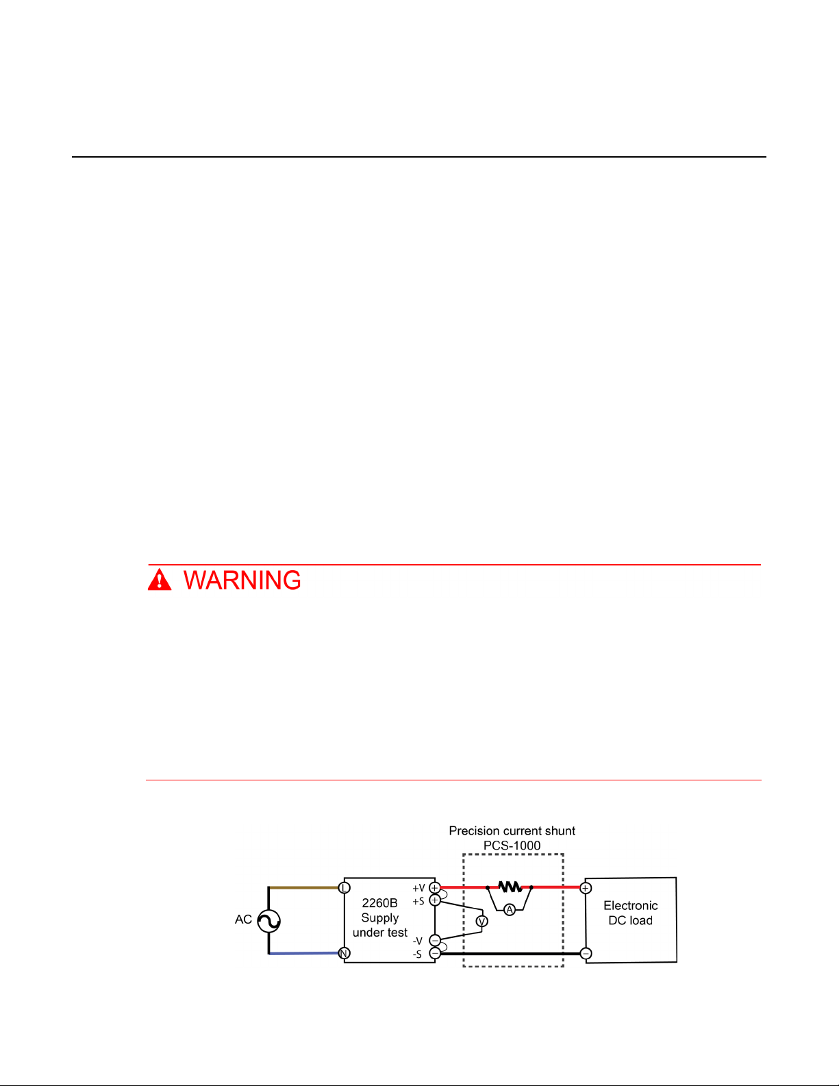
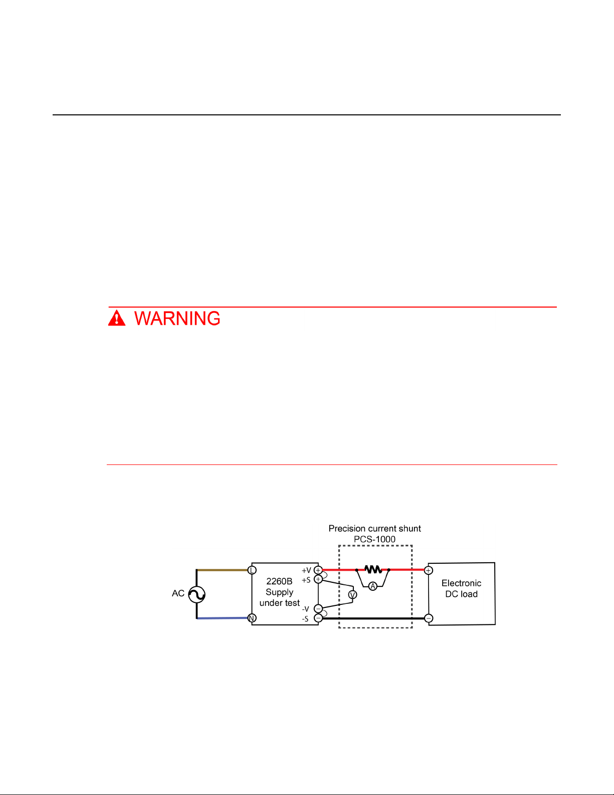
1. Connect the ac power supply to the 2260B.
2. Connect the DMM on the PCS-1000 directly across the +S and -S terminals to an electronic dc
load, as shown in the previous figure.
3. Turn on the 2260B and, if necessary, all of the other instruments.
4. Press the Set button on your 2260B and program the output voltage to 0.1 and the output current
to its maximum value with the load off (see Series 2260B available models (on page 1-2
)).
5. On the 2260B press the Output button. Note that CV is displayed on the 2260B front panel and
the output current reading on the PCS-1000 should be approximately zero.
6. Record the DMM output voltage reading and the voltage indicated on the 2260B. The readings
should be within the limits specified in the test record form for the appropriate model (see
Verification test record forms (on page 5-1
) for the appropriate model, under Voltage
Programming and Measurement).
7. Program the output voltage to its maximum rated value (see Series 2260B available models (on
page 1-2)).
8. Record the DMM output voltage reading and the voltage indicated on the 2260B.
The readings should be within the limits specified in the test record form for the appropriate model
(see Verification test record forms (on page 5-1
) for the appropriate model, under Voltage
Programming and Measurement).
Verifying voltage programming and measurement accuracy is complete.
3-2 077104803 / June 2021
Page 14
Series 2260B
Constant voltage verification
Programmable Power Supplies Verification and Adjustment Manual Section 3:
Constant voltage load regulation verification
This test measures the change in output voltage resulting from a change from full load to no load.
Hazardous voltages may be present on all output and guard terminals. To prevent electrical
shock that could cause injury or death, never make or break connections to any of the
instruments used for this verification test while instruments are powered on. Turn off the
2260B instrument from the front panel or disconnect the main power cord from the rear of the
instrument before handling cables. Putting the equipment into an output-off state does not
guarantee that the outputs are powered off if a hardware or software fault occurs.
Precautions must be taken to prevent a shock hazard by surrounding the test device and any
unprotected leads (wiring) with double insulation for up to 800 volts depending on the power
supply that you have, Category I.
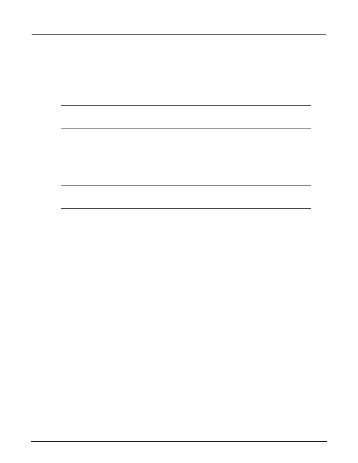
Figure 2: 2260B Constant voltage load regulation
Before proceeding, make sure that the 2260B instrument is off.
077104803 / June 2021 3-3
Page 15

Section
Verification and Adjustment Manual
3: Constant voltage verification Series 2260B Programmable Power Supplies
To perform CV load regulation verification:
1. Connect the ac power supply to the 2260B.
2. Connect the DMM on the PCS-1000 directly across the +S and -S terminals to an electronic dc
load, as shown in the previous figure.
3. Turn on the 2260B and, if necessary, all of the other instruments.
4. Press the Set button on your 2260B and program the output current to its maximum value and
the output voltage to the maximum rated value (see Series 2260B available models
(on page
1-2)).
5. On the 2260B press the Output button.
6. On the electronic dc load instrument, set the output load to 1 A. Note that CV is displayed on the
2260B front panel. If CV is not displayed, adjust the load so that the output current drops and CV
is displayed.
7. Record the DMM output voltage reading.
8. Open the load and record the DMM voltage reading.
The difference between the DMM readings in steps 7 and 8 is the load effect, which should not
exceed the value listed in the test record form (see Verification test record forms (on page 5-1
) for the
appropriate model, under CV load regulation).
Verifying CV load regulation is complete.
3-4 077104803 / June 2021
Page 16
Series 2260B
Constant voltage verification
Programmable Power Supplies Verification and Adjustment Manual Section 3:
Constant voltage line regulation verification
This test measures the change in output voltage resulting from a change in ac line voltage from the
minimum to maximum value within the line voltage specifications.
Hazardous voltages may be present on all output and guard terminals. To prevent electrical
shock that could cause injury or death, never make or break connections to any of the
instruments used for this verification test while instruments are powered on. Turn off the
2260B instrument from the front panel or disconnect the main power cord from the rear of the
instrument before handling cables. Putting the equipment into an output-off state does not
guarantee that the outputs are powered off if a hardware or software fault occurs.
Precautions must be taken to prevent a shock hazard by surrounding the test device and any
unprotected leads (wiring) with double insulation for up to 800 volts depending on the power
supply that you have, Category I.
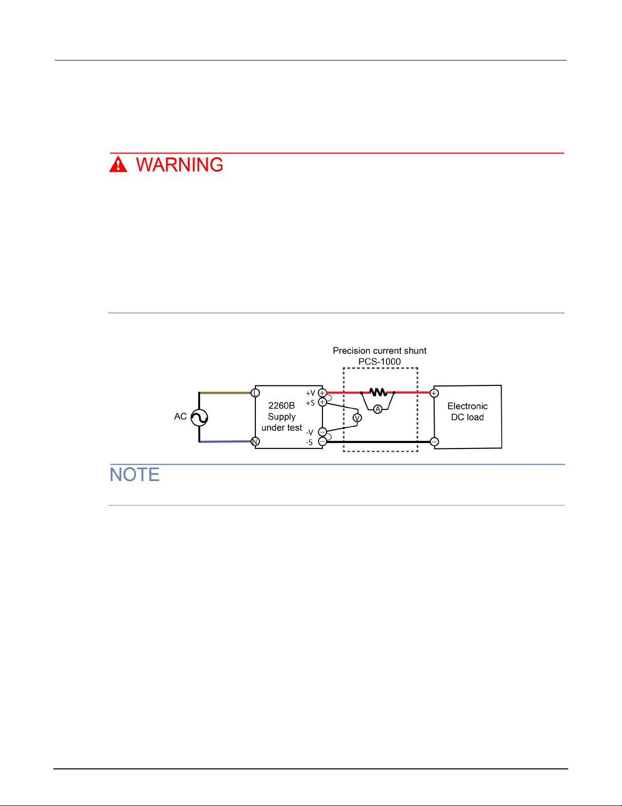
Figure 3: 2260B Constant voltage line regulation
Before proceeding, make sure that the 2260B instrument is off.
077104803 / June 2021 3-5
Page 17

Section
Verification and Adjustment Manual
3: Constant voltage verification Series 2260B Programmable Power Supplies
To perform CV line regulation verification:
1. Connect the ac power supply to the 2260B.
2. Connect the DMM on the PCS-1000 directly across the +S and -S terminals to an electronic dc
load, as shown in the previous figure.
3. Turn on the 2260B and, if necessary, all of the other instruments.
4. Set the variable ac voltage to nominal line voltage.
5. Press the Set button on the 2260B and program the output current to its maximum value and the
output voltage to its maximum rated value (see Series 2260B available models (on page 1-2
)).
6. On the 2260B press the Output button.
7. On the electronic dc load instrument, set the electronic output load to 1 A. Note that CV is
displayed on the 2260B front panel. If CV is not displayed, adjust the load so that the output
current drops and CV is displayed.
8. Adjust the ac power source to the low-line voltage (85 V ac for 100/120 nominal line; 170 V ac for
200/240 nominal line).
9. Record the DMM output voltage reading.
10. Adjust the ac power source to the high-line voltage (132 V ac for 100/120 nominal line; 265 V ac
for 200/240 nominal line).
11. Record the DMM output voltage reading.
The difference between the DMM reading in steps 9 and 11 is the source effect, which should not
exceed the value listed in the test record form (see Verification test record forms (on page 5-1
) for the
appropriate model, under CV line regulation).
Verifying CV line regulation is complete.
3-6 077104803 / June 2021
Page 18
Series 2260B
fication
Programmable Power Supplies Verification and Adjustment Manual Section 3: Constant voltage veri
Constant voltage ripple and noise verification
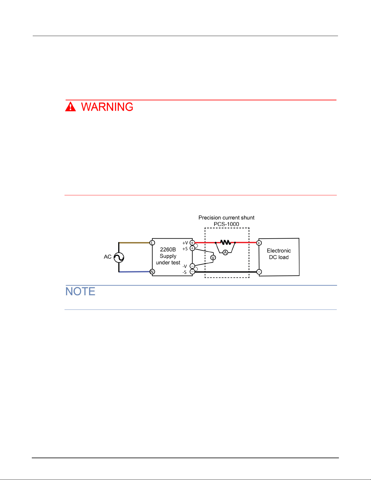
This test measures the dc output voltage with the (10:1) 50 Ω probe.
Hazardous voltages may be present on all output and guard terminals. To prevent electrical
shock that could cause injury or death, never make or break connections to any of the
instruments used for this verification test while instruments are powered on. Turn off the
2260B instrument from the front panel or disconnect the main power cord from the rear of the
instrument before handling cables. Putting the equipment into an output-off state does not
guarantee that the outputs are powered off if a hardware or software fault occurs.
Precautions must be taken to prevent a shock hazard by surrounding the test device and any
unprotected leads (wiring) with double insulation for up to 800 volts depending on the power
supply that you have, Category I.
Figure 4: 2260B Constant voltage ripple noise verification
Before proceeding, make sure that the 2260B instrument is off.
077104803 / June 2021 3-7
Page 19

Section
Verification and Adjustment Manual
3: Constant voltage verification Series 2260B Programmable Power Supplies
To perform CV ripple and noise verification:
1. Connect the ac power supply to the 2260B.
2. Connect the DMM on the PCS-1000 directly across the +S and -S terminals to an electronic dc
load, as shown in the previous figure.
3. Turn on the 2260B and, if necessary, all of the other instruments.
4. On the oscilloscope, set the ac coupling to 20 MHz bandwidth, the scale to 10 mV Sampling
mode to average, and the measurement to peak-to-peak.
5. Press the Set button on your 2260B and program the power supply to output current to its
maximum value and the output voltage to its maximum rated value (see
Series 2260B available
models (on page 1-2)).
6. On the 2260B press the Output button. Let the oscilloscope run for 20 seconds in order to
generate enough measurement points. The result should not exceed the peak-to-peak limits in
the test record form.
7. Use the DMM to measure the RMS noise voltage using ac voltage (see next figure).
The result should not exceed the RMS limits in the test record form (see Verification test record forms
(on page 5-1) for the appropriate model, under CV ripple and noise - RMS).
Verifying CV ripple and noise is complete.
3-8 077104803 / June 2021
Page 20
Constant current (CC) verification tests ................................... 4-1
Constant current verification
In this section:
Constant current (CC) verification tests
There are four verification tests in this series. These tests verify display panel accuracy, verify
programmed voltage, measure output voltage changes based on load or no load, measure output
voltage based ac line voltage changes, and measure output noise.
Section 4
Current programming and measurement accuracy verification
This test verifies that the current programming and measurement functions are within specifications.
Hazardous voltages may be present on all output and guard terminals. To prevent electrical
shock that could cause injury or death, never make or break connections to any of the
instruments used for this verification test while instruments are powered on. Turn off the
2260B instrument from the front panel or disconnect the main power cord from the rear of the
instrument before handling cables. Putting the equipment into an output-off state does not
guarantee that the outputs are powered off if a hardware or software fault occurs.
Precautions must be taken to prevent a shock hazard by surrounding the test device and any
unprotected leads (wiring) with double insulation for up to 800 volts depending on the power
supply that you have, Category I.
Figure 5: 2260B Current analog adjustment devices
Page 21

Section
Verification and Adjustment Manual
4: Constant current verification Series 2260B Programmable Power Supplies
Before proceeding, make sure that the 2260B instrument is off.
To perform current programming and measurement accuracy:
1. Connect the ac power supply.
2. Connect the current input on the PCS-1000 across the +S and -S terminals through an electronic
dc load, as shown in the previous figure.
3. Turn on the 2260B and, if necessary, all of the other instruments.
4. Press the Set button on the 2260B, program the output voltage to 15 volts and set the output
current to zero (see Series 2260B available models (on page 1-2
), if needed).
5. Set the electronic load to a short and on the 2260B press the Output button. Note that CC is
displayed on the 2260B front panel.
6. Record the precision current shunt (PCS-1000) input current readings and the current indicated
on the 2260B. The readings should be within the limits specified in the test record form for the
appropriate model (see Verification test record forms (on page 5-1
) for the appropriate model,
under Current Programming and Measurement, if needed).
7. Program the output current to its maximum rated value (see Series 2260B available models (on
page 1-2), if needed).
8. Set the electronic load to a short.
9. Record the precision current shunt (PCS-1000) input current readings and the current indicated
on the 2260B.
The readings should be within the limits specified in the test record form for the appropriate model
(see Verification test record forms (on page 5-1
) for the appropriate model, under Current
Programming and Measurement, if needed).
Verifying Current Programming and Measurement Accuracy is complete.
4-2 077104803 / June 2021
Page 22

Series 2260B
Constant current verification
Programmable Power Supplies Verification and Adjustment Manual Section 4:
Constant current load regulation verification
This test measures the change in output current resulting from a change from full scale to short
circuit.
Hazardous voltages may be present on all output and guard terminals. To prevent electrical
shock that could cause injury or death, never make or break connections to any of the
instruments used for this verification test while instruments are powered on. Turn off the
2260B instrument from the front panel or disconnect the main power cord from the rear of the
instrument before handling cables. Putting the equipment into an output-off state does not
guarantee that the outputs are powered off if a hardware or software fault occurs.
Precautions must be taken to prevent a shock hazard by surrounding the test device and any
unprotected leads (wiring) with double insulation for up to 800 volts depending on the power
supply that you have, Category I.
Figure 6: 2260B Constant current load regulation
Before proceeding, make sure that the 2260B instrument is off.
077104803 / June 2021 4-3
Page 23

Section
Verification and Adjustment Manual
4: Constant current verification Series 2260B Programmable Power Supplies
To perform CC load regulation verification:
1. Connect the ac power supply.
2. Connect the current input on the PCS-1000 across the +S and -S terminals through an electronic
dc load, as shown in the previous figure.
3. Turn on the 2260B and, if necessary, all of the other instruments.
4. With the electronic load in CR mode, press the Set button and program the 2260B output voltage
to 15 volts.
5. Press the Output button on your 2260B.
6. Using the electronic load, set the output current to the maximum rated output. Note that CC is
displayed on the 2260B front panel. If CC is not displayed, adjust the load so that the voltage
drops and CC is displayed.
7. Record the PCS-1000 input current reading.
8. Short the electronic load and record the indicated current reading on the PCS-1000.
The difference in the current readings in steps 7 and 8 is the load effect, which should not exceed the
value listed in the test record form for the appropriate model (see Verification test record forms
(on
page 5-1) for the appropriate model, under CC load regulation, if needed).
Verifying CC load regulation is complete.
4-4 077104803 / June 2021
Page 24
Series 2260B
t verification
Programmable Power Supplies Verification and Adjustment Manual Section 4: Constant curren
Constant current line regulation verification
This test measures the change in output current that results from a change in ac line voltage from the
minimum to maximum value within the line voltage specifications.
Hazardous voltages may be present on all output and guard terminals. To prevent electrical
shock that could cause injury or death, never make or break connections to any of the
instruments used for this verification test while instruments are powered on. Turn off the
2260B instrument from the front panel or disconnect the main power cord from the rear of the
instrument before handling cables. Putting the equipment into an output-off state does not
guarantee that the outputs are powered off if a hardware or software fault occurs.
Precautions must be taken to prevent a shock hazard by surrounding the test device and any
unprotected leads (wiring) with double insulation for up to 800 volts depending on the power
supply that you have, Category I.
Figure 7: 2260B Constant current line regulation
Before proceeding, make sure that the 2260B instrument is off.
077104803 / June 2021 4-5
Page 25

Section
Verification and Adjustment Manual
4: Constant current verification Series 2260B Programmable Power Supplies
To perform CC line regulation verification:
1. Connect the ac power supply.
2. Connect the PCS-1000 current input across the +S and -S terminals through an electronic dc load,
as shown in the previous figure.
3. Turn on the 2260B and, if necessary, all of the other instruments.
4. Set the variable ac voltage to nominal line voltage.
5. On your 2260B press the Set button and program the output current to its maximum rated value
(see Series 2260B available models (on page 1-2
), if needed).
6. Press the Output button on your 2260B.
7. With the electronic load in CR mode short the load and program the 2260B output voltage to 15
volts. Note that CC is displayed on the 2260B front panel. If CC is not displayed, adjust the load
so that the voltage drops and CC is displayed.
8. Adjust the ac power source to the low-line voltage (85 V ac for 100/120 nominal line; 170 V ac for
200/240 nominal line).
9. Record the PCS-1000 input current reading.
10. Adjust the ac power source to the high-line voltage (132 V ac for 100/120 nominal line; 265 V ac
for 200/240 nominal line).
11. Record the PCS-1000 input current reading.
The difference between the PCS-1000 reading in steps 9 and 11 is the source effect, which should
not exceed the value listed in the test record form (see Verification test record forms (on page 5-1
) for
the appropriate model, under CV line regulation, if needed).
Verifying CC line regulation is complete.
4-6 077104803 / June 2021
Page 26

Series 2260B
Constant current verification
Programmable Power Supplies Verification and Adjustment Manual Section 4:
Constant current noise verification
This test measures the ac output voltage with the PCS-1000 and DMM.
Hazardous voltages may be present on all output and guard terminals. To prevent electrical
shock that could cause injury or death, never make or break connections to any of the
instruments used for this verification test while instruments are powered on. Turn off the
2260B instrument from the front panel or disconnect the main power cord from the rear of the
instrument before handling cables. Putting the equipment into an output-off state does not
guarantee that the outputs are powered off if a hardware or software fault occurs.
Precautions must be taken to prevent a shock hazard by surrounding the test device and any
unprotected leads (wiring) with double insulation for up to 800 volts depending on the power
supply that you have, Category I.
Figure 8: 2260B Constant current noise verification
Before proceeding, make sure that the 2260B instrument is off.
077104803 / June 2021 4-7
Page 27

Section
Verification and Adjustment Manual
4: Constant current verification Series 2260B Programmable Power Supplies
To perform CC noise verification:
1. Connect the ac power supply.
2. Connect the PCS-1000 current input across the +S and -S terminals through an electronic dc load
(see previous figure).
3. Turn on the 2260B and, if necessary, all of the other instruments.
4. Press the Set button on your 2260B and program the power supply output current to its maximum
value and the output voltage to 15 volts (see Series 2260B available models (on page 1-2
), if
needed).
5. On the 2260B press the Output button.
6. Use the DMM to measure the RMS noise voltage using ac voltage (see previous figure).
The result should not exceed the RMS limits in the test record form (see Verification test record forms
(on page 5-1) for the appropriate model, under CV ripple and noise - RMS, if needed).
Verifying CC ripple and noise is complete.
4-8 077104803 / June 2021
Page 28

800 Volt verification record ....................................................... 5-8
Section 5
Verification test record forms
In this section:
30 Volt verification test record .................................................. 5-1
80 Volt verification test record .................................................. 5-3
250 Volt verification record ....................................................... 5-6
Page 29

Section
Verification and Adjustment Manual
Model 2260B-30-36
2260B-30-72
2260B-30-108
Serial number:
Verified by
Name:
Company/contact:
Year:
Month:
Day:
Environment
Temperature:
Humidity:
Minimum voltage out
All
-10 mV
+10 mV
Measurement accuracy
All
-20 mV
+20 mV
Rated voltage out
All
29.960 V
30.040 V
Measurement accuracy
All
29.95 V
30.5 V
All
-20 mV
+20 mV
Peak-to-peak
30-36
N/A 60 mV
30-72
N/A 80 mV
30-108
N/A 100 mV
RMS
30-36
N/A 7 mV
30-72
N/A 11 mV
30-108
N/A 14 mV
5: Verification test record forms Series 2260B Programmable Power Supplies
30 Volt verification test record
Print this page and record your verification results that can be used for reference in the future. Make
sure to keep this record with your power supply.
Constant voltage tests:
Voltage programming
and measurement
CV load regulation Model
CV line regulation Model
All -18 mV +18 mV
Model
Minimum
specifications
Minimum
specifications
Minimum
specifications
Results Maximum specifications
Results Maximum specifications
Results Maximum specifications
CV ripple and noise Model
5-2 077104803 / June 2021
Minimum
specifications
Results Maximum specifications
Page 30

Series 2260B
cation test record forms
Minimum current out
30-36
-30 mA
+30 mA
30-72
-60 mA
+60 mA
30-108
-100 mA
+100 mA
Measurement accuracy
30-36
-40 mA
+40 mA
30-72
-70 mA
+70 mA
30-108
-100 mA
+100 mA
Rated current out
30-36
35.934 A
36.066 A
30-72
71.898 A
72.102 A
30-108
107.862 A
108.138 A
Measurement accuracy
30-36
35.924 A
36.076 A
30-72
71.858 A
72.142 A
30-108
107.79 A
108.21 A
30-36
-41 mA
+41 mA
30-72
-77 mA
+77mA
30-108
-113 mA
+113 mA
30-36
-41 mA
+41 mA
30-72
-77 mA
+77mA
30-108
-113 mA
+113 mA
Programmable Power Supplies Verification and Adjustment Manual Section 5: Verifi
Constant current tests:
Current programming
and measurement
Model
Minimum
specifications
Results Maximum specifications
CC load regulation Model
CC line regulation Model
Minimum
specifications
Minimum
specifications
Results Maximum specifications
Results Maximum specifications
077104803 / June 2021 5-3
Page 31

Section
Verification and Adjustment Manual
Model 2260B-80-13
2260B-80-27
2260B-80-40
Serial number:
Verified by
Name:
Company/contact:
Year:
Month:
Day:
Environment
Temperature:
Humidity:
Minimum voltage out
All
-10 mV
+10 mV
Measurement accuracy
All
-20 mV
+20 mV
Rated voltage out
All
79.91 V
80.090 V
Measurement accuracy
All
79.9 V
80.1 V
All
-45 mV
+45 mV
All
-43 mV
+43 mV
Peak-to-peak
80-13
N/A 60 mV
80-27
N/A 80 mV
80-40
N/A 100 mV
RMS
80-13
N/A 7 mV
80-27
N/A 11 mV
80-40
N/A 14 mV
5: Verification test record forms Series 2260B Programmable Power Supplies
80 Volt verification test record
Print this page and record your verification results that can be used for reference in the future. Make
sure to keep this record with your power supply.
Constant voltage tests:
Voltage programming
and measurement
CV load regulation Model
Model
Minimum
specifications
Minimum
specifications
Results Maximum specifications
Results Maximum specifications
CV line regulation Model
CV ripple and noise Model
Minimum
specifications
Minimum
specifications
Results Maximum specifications
Results Maximum specifications
5-4 077104803 / June 2021
Page 32

Series 2260B
Verification test record forms
Minimum current out
80-13
-10 mA
+10 mA
80-27
-30 mA
+30 mA
80-40
-40 mA
+40 mA
Measurement accuracy
80-13
-20 mA
+20 mA
80-27
-40 mA
+40 mA
80-40
-50 mA
+50 mA
Rated current out
80-13
12.87 A
13.13 A
80-27
26.943 A
27.057 A
80-40
39.92 A
40.080 A
Measurement accuracy
80-13
12.967 A
13.033 A
80-27
26.933 A
27.067 A
80-40
39.91 A
30.09 A
80-13
-18 mA
+18 mA
80-27
-32 mA
+32 mA
80-40
-45 mA
+45 mA
Programmable Power Supplies Verification and Adjustment Manual Section 5:
Constant current tests:
Current programming
and measurement
Model
Minimum
specifications
Results Maximum specifications
CC load regulation Model
Minimum
Results Maximum specifications
specifications
CC line regulation Model
Minimum
Results Maximum specifications
specifications
80-13 -18 mA +18 mA
80-27 -32 mA +32 mA
80-40 -45 mA +45 mA
077104803 / June 2021 5-5
Page 33

Section
Verification and Adjustment Manual
Model 2260B-250-4
2260B-250-9
2260B-250-13
Serial number:
Verified by
Name:
Company/contact:
Year:
Month:
Day:
Environment
Temperature:
Humidity:
Minimum voltage out
All
-200 mV
+200 mV
Measurement accuracy
All
-200 mV
+200 mV
Rated voltage out
All
249.55 V
250.45 V
Measurement accuracy
All
249.55 V
250.45 V
All
-130 mV
+130 mV
All
-128 mV
+128 mV
Peak-to-peak
250-4
N/A 80 mV
250-9
N/A 100 mV
250-13
N/A 120 mV
RMS
250-4
N/A 15 mV
250-9
N/A 15 mV
250-13
N/A 15 mV
5: Verification test record forms Series 2260B Programmable Power Supplies
250 Volt verification record
Print this page and record your verification results that can be used for reference in the future. Make
sure to keep this record with your power supply.
Constant voltage tests:
Voltage programming
and measurement
CV load regulation Model
CV line regulation Model
Model
Minimum
specifications
Minimum
specifications
Minimum
specifications
Results Maximum specifications
Results Maximum specifications
Results Maximum specifications
CV ripple and noise Model
5-6 077104803 / June 2021
Minimum
specifications
Results Maximum specifications
Page 34

Series 2260B
Verification test record forms
Minimum current out
250-4
-5 mA
+5 mA
250-9
-10 mA
+10 mA
250-13
-15 mA
+15 mA
Measurement accuracy
250-4
-5 mA
+5 mA
250-9
-10 mA
+10 mA
250-13
-20 mA
+20 mA
Rated current out
250-4
3.991 A
4.001 A
250-9
8.9810 A
9.0190 A
250-13
12.972 A
13.028 A
Measurement accuracy
250-4
3.991 mA
4.001 mA
250-9
8.981 A
9.019 A
250-13
12.967 A
13.033 A
250-4
-9.000 mA
+9.000 mA
250-9
-14.000 mA
+14.000 mA
250-13
-18.00 mA
+18.00 mA
250-4
-9.5 mA
+9.5 mA
250-9
-14 mA
+14 mA
250-13
-18.5 mA
+18.5 mA
Programmable Power Supplies Verification and Adjustment Manual Section 5:
Constant current tests:
Current programming
and measurement
Model
Minimum
specifications
Results Maximum specifications
CC load regulation Model
CC line regulation Model
Minimum
specifications
Minimum
specifications
Results Maximum specifications
Results Maximum specifications
077104803 / June 2021 5-7
Page 35

Section
Verification and Adjustment Manual
Model 2260B-800-1
2260B-800-2
2260B-800-4
Serial number:
Verified by
Name:
Company/contact:
Year:
Month:
Day:
Environment
Temperature:
Humidity:
Minimum voltage out
All
-400 mV
+400 mV
Measurement accuracy
All
-400 mV
+400 mV
Rated voltage out
All
798.8 V
801.2 V
Measurement accuracy
All
798.8 V
801.2 V
All
-405 mV
+405 mV
All
-403 mV
+403 mV
Peak-to-peak
800-1
N/A 150 mV
800-2
N/A 200 mV
800-4
N/A 200 mV
RMS
800-1
N/A 30 mV
800-2
N/A 30 mV
800-4
N/A 30 mV
5: Verification test record forms Series 2260B Programmable Power Supplies
800 Volt verification record
Print this page and record your verification results that can be used for reference in the future. Make
sure to keep this record with your power supply.
Constant voltage tests:
Voltage programming
and measurement
CV load regulation Model
Model
Minimum
specifications
Minimum
specifications
Results Maximum specifications
Results Maximum specifications
CV line regulation Model
CV ripple and noise Model
Minimum
specifications
Minimum
specifications
Results Maximum specifications
Results Maximum specifications
5-8 077104803 / June 2021
Page 36

Series 2260B
Verification test record forms
Minimum current out
800-1
-2 mA
+2 mA
800-2
-4 mA
+4 mA
800-4
-6 mA
+6 mA
Measurement accuracy
800-1
-2 mA
+2 mA
800-2
-4 mA
+4 mA
800-4
-6 mA
+6 mA
Rated current out
800-1
0.997 A
1.003 A
800-2
1.994 A
2.006 A
800-4
3.936 A
4.064 A
Measurement accuracy
800-1
0.997 A
1.003 A
800-2
1.994 A
2.006 A
800-4
3.936 A
4.064 A
800-1
-6.00 mA
+6.00 mA
800-2
-7.00 mA
+7.00 mA
800-4
-9.00 mA
+9.00 mA
800-1
-6.00 mA
+6.00 mA
800-2
-7.00 mA
+7.00 mA
800-4
-9.00 mA
+9.00 mA
Constant current tests:
Current programming
and measurement
Programmable Power Supplies Verification and Adjustment Manual Section 5:
Model
Minimum
specifications
Results Maximum specifications
CC load regulation Model
CC line regulation Model
Minimum
specifications
Minimum
specifications
Results Maximum specifications
Results Maximum specifications
077104803 / June 2021 5-9
Page 37

Adjustment equipment ............................................................. 6-1
Precision current shunt
3 A (0.1 Ω) 0.01% TC = 3 ppm / °C
GW Instek PCS-1000 or
30 A (0.01 Ω) 0.01% TC = 10 ppm / °C
300 A (0.001 Ω) 0.02% TC = 10 ppm / °C
Electronic loads
80 V, 280 A minimum with transient capability
and a slew rate of 2.8 A/μs or better.
Various manufacturers of
500 V, 40 A minimum with transient capability
and a slew rate of 0.4 A/μs or better.
850 V, 40 A minimum with transient capability
and a slew rate of 0.4 A/μs or better.
DC power supply
Voltage resolution: 1 mV
Keithley programmable
supply 2220-30-01
Accuracy: <0.05% mV of reading
Voltage resolution: 0.1 mV
Keithley DMM 7510 or
Accuracy: <0.01% mV of reading
In this section:
Adjustment equipment
The following is a list of the recommended equipment used for calibrating the programmable DC
power supplies:
Section 6
2260B Adjustment equipment
Type Specifications Recommended instrument
Digital multimeter
equivalent
programmable DC
electronic loads
dual-channel DC power
equivalent
Page 38

Analog interface adjustment procedure .................................... 7-3
In this section:
Remove top cover .................................................................... 7-1
Confirm location of adjustment points ...................................... 7-2
Remove top cover
Hazardous voltages may be present on all output and guard terminals. To prevent electrical
shock that could cause injury or death, never make or break connections to any of the
instruments used for this adjustment while instruments are powered on. Turn off all of the
instruments from the front panel or disconnect the main power cord from the rear of the
instrument before handling cables. Putting the equipment into an output-off state does not
guarantee that the outputs are powered off if a hardware or software fault occurs.
Precautions must be taken to prevent a shock hazard by surrounding the test device and any
unprotected leads (wiring) with double insulation for up to 800 volts depending on the power
supply that you have, Category I.
Section 7
Analog interface adjustment
Before you can make adjustments on the instrument, you will need to remove the 2260B top cover.
On the 360 watt models (2260B-30-36, 2260B-80-13, 2260B-250-4, and 2260B-800-01), note that
there are nine screws that you will need to remove in order to remove the top cover (see next figure).
The next figure only shows seven screws.
Page 39
Section
Verification and Adjustment Manual
7: Analog interface adjustment Series 2260B Programmable Power Supplies
On the 720 watt models (2260B-30-72, 2260B-80-27, 2260B-250-9, 2260B-800-2), there are ten
screws that you will need to remove.
On the 1080 watt models (2260B-30-108, 2260B-80-40, 2260B-250-13, 2260B-800-4), there are
eleven screws that you will need to remove.
Figure 9: 2260B Top cover
Confirm location of adjustment points
The location of the adjustment points, on the 2260B circuit board (VR400 and VR401), are shown in
the next figure:
Figure 10: 2260B circuit board
7-2 077104803 / June 2021
Page 40

Series 2260B
Analog interface adjustment
Programmable Power Supplies Verification and Adjustment Manual Section 7:
Make sure that you connect the following devices as indicated in the next figure. Also, make sure that
you set the Model 2220-30-1 DC power supply, channel one, and channel two to 10.00 V.
Figure 11: Analog adjustment devices
Analog interface adjustment procedure
To start the adjustment procedure:
1. Turn on the programmable DC power supply (Series 2260B) by pressing the Function key.
When the function key is illuminated, the display indicates "F - 01." Additionally, note that the "x" in
the diagram below indicates that the value is not fixed.
2. Rotate the Voltage knob until the display indicates "F - 00".
077104803 / June 2021 7-3
Page 41
Section
Verification and Adjustment Manual
2260B-30-36
3036
2260B-30-72
3072
2260B-30-108
3010
2260B-80-13
8013
2260B-80-27
8027
2260B-80-40
8040
2260B-250-4
2545
2260B-250-9
2509
2260B-250-13
2515
2260B-800-1
8014
2260B-800-2
8028
2260B-800-4
8043
7: Analog interface adjustment Series 2260B Programmable Power Supplies
3. Press the Current knob to select the numeric indicator.
4. Use the Current knob to select the appropriate password for the model that you are calibrating.
The following is a list of models and passwords:
Model number Password
5. Press the Current knob to enter the password (note that the highlighted numeral is the one that
you are changing).
6. Once the number needed is highlighted, press the Current knob to move to the next numeric
position.
7. Press the Voltage knob to enter the password.
The display will indicate "C000".
8. Turn on the external power supply (the 2220-30-01) and set the output to 10.000 V ±0.001 V, for
both channel 1 and 2.
9. Press the Voltage knob to prepare to execute the external output voltage adjustment (C010).
Make sure that the DC electronic load instrument is turned off.
7-4 077104803 / June 2021
Page 42

Series 2260B
Analog interface adjustment
2260B-30-36
29.994
30.006
2260B-30-108
29.994
30.006
2260B-80-13
79.984
80.016
2260B-80-27
79.984
80.016
2260B-80-40
79.984
80.016
2260B-250-4
249.950
250.050
2260B-250-9
249.950
250.050
2260B-800-1
799.840
800.160
2260B-800-2
799.840
800.160
2260B-800-4
799.840
800.160
Programmable Power Supplies Verification and Adjustment Manual Section 7:
10. Press the Voltage knob (C011 is displayed); the 2260B instrument Output button illuminates and
CV is displayed.
Make sure that the reading on the DMM is within the specified voltage range. If not, adjust the
voltage resistor (VR401) on the 2260B instrument (see Confirm location of adjustment points
(on
page 7-2)).
The following is a list of models with adjustment ranges for point VR401:
Model number minimum volts maximum volts
2260B-30-72 29.994 30.006
2260B-250-13 249.950 250.050
11. Press the Voltage knob to return to external voltage adjustment (C010).
12. Rotate the Voltage knob until it indicates C020, in order to prepare to execute the external output
current adjustment.
Make sure that the load key and short key on the DC electronic load instrument are turned on.
077104803 / June 2021 7-5
Page 43
Section
Verification and Adjustment Manual
2260B-30-36
35.9928
36.0072
2260B-30-72
71.9856
72.0144
2260B-30-108
107.9784
108.0216
2260B-80-13
13.4973
13.5027
2260B-80-27
26.9946
27.0054
2260B-80-40
40.4919
40.5081
2260B-250-9
8.9982
9.0018
2260B-250-13
13.4973
13.5027
2260B-800-1
1.4397
1.4403
2260B-800-2
2.8794
2.8806
2260B-800-4
4.3191
4.3209
7: Analog interface adjustment Series 2260B Programmable Power Supplies
13. Press the Voltage knob (C021 is displayed); the 2260B Output button illuminates and CC is
displayed.
Make sure that the reading on the PCS-1000 current meter is within the specified current range. If
not, adjust the current resistor (VR400) on the 2260B instrument (see
Confirm location of adjustment
points (on page 7-2)).
The following is a list of models with adjustment ranges for point VR401:
Model number minimum current maximum current
2260B-250-4 4.4991 4.5009
14. Press the Voltage knob to return to the external current adjustment (C020).
15. Rotate the Voltage knob to exit the external current adjustment display (C030 is displayed).
16. Press the Voltage knob to return to the main adjustment display.
7-6 077104803 / June 2021
Page 44

Series 2260B
Analog interface adjustment
Programmable Power Supplies Verification and Adjustment Manual Section 7:
17. Rotate the Current knob to exit adjustment mode (C000:2).
18. Press the Voltage knob to exit adjustment mode.
The "x" in the diagram above indicates that the value is not fixed.
Turn off the 2600B instrument and put the top cover back on.
Analog interface adjustment is complete.
077104803 / June 2021 7-7
Page 45
Constant voltage (CV) adjustment procedure .......................... 8-2
In this section:
Connect device equipment ....................................................... 8-1
Connect device equipment
Hazardous voltages may be present on all output and guard terminals. To prevent electrical
shock that could cause injury or death, never make or break connections to any of the
instruments used for this adjustment while instruments are powered on. Turn off all of the
instruments from the front panel or disconnect the main power cord from the rear of the
instrument before handling cables. Putting the equipment into an output-off state does not
guarantee that the outputs are powered off if a hardware or software fault occurs.
Precautions must be taken to prevent a shock hazard by surrounding the test device and any
unprotected leads (wiring) with double insulation for up to 800 volts depending on the power
supply that you have, Category I.
Section 8
Constant voltage adjustment
Make sure that you connect the following devices as indicated in the next figure.
Figure 12: 2260B Constant voltage adjustment devices
Page 46

Section
Verification and Adjustment Manual
2260B-30-36
3036
2260B-30-72
3072
2260B-30-108
3010
2260B-80-13
8013
2260B-80-27
8027
2260B-80-40
8040
2260B-250-4
2545
2260B-250-9
2509
2260B-250-13
2515
2260B-800-1
8014
2260B-800-2
8028
2260B-800-4
8043
8: Constant voltage adjustment Series 2260B Programmable Power Supplies
Constant voltage (CV) adjustment procedure
To start the adjustment procedure:
1. Turn on the programmable DC power supply (Series 2260B) by pressing the Function key.
The function key lights up, the display indicates "F - 01." Additionally, note that the "x" in the diagram
below indicates that the value is not fixed.
2. Rotate the voltage knob until it indicates "F - 00".
3. Use the Current knob to select the appropriate password for the model that you are calibrating.
The following is a list of models and passwords:
Model number Password
8-2 077104803 / June 2021
Page 47

Series 2260B
Constant voltage adjustment
Programmable Power Supplies Verification and Adjustment Manual Section 8:
4. Press the voltage knob to enter the enter the password.
The display will indicate "C000".
5. Use the current knob to enter "constant voltage" adjustment mode. To enter adjustment mode,
rotate the current knob until "1" is displayed on the bottom display (C000:1).
6. Press the voltage knob to enter voltage adjustment (C110).
7. Press the voltage knob two times to enter the voltage offset adjustment (C111).
8. Press the voltage knob to set the offset voltage value (C112).
The "x" in the diagram above indicates that the value is not fixed.
077104803 / June 2021 8-3
Page 48
Section
Adjustment Manual
8: Constant voltage adjustment Series 2260B Programmable Power Supplies Verification and
9. Rotate the current knob to set the offset value on the 2260B display so that it is the same as the
reading on the PCS-1000 voltmeter.
10. Press the voltage knob to enter the output voltage middle adjustment (C113).
11. Press the voltage knob to set the middle voltage value.
The "x" in the diagram above indicates that the value is not fixed.
12. Rotate the current knob to set the middle voltage value on the 2260B display so that it is the
same as the reading on the PCS-1000 voltmeter.
13. Press the voltage knob to enter the output voltage full-scale adjustment (C115).
14. Press the voltage knob to set the full-scale voltage value (C116).
The "x" in the diagram above indicates that the value is not fixed.
15. Rotate the current knob to set the full-scale voltage value on the 2260B display so that it is the
same as the reading on the PCS-1000 voltmeter.
16. Press the voltage knob to enter the OVP (overvoltage protection) adjustment (C117).
8-4 077104803 / June 2021
Page 49

Series 2260B
Constant voltage adjustment
Programmable Power Supplies Verification and Adjustment Manual Section 8:
17. Press the voltage knob to start the automatic OVP adjustment (C118).
The display will indicate "OK" when the adjustment is complete for approximately five seconds.
Additionally, the output turns on and the CV indicator is lit. Also, the instrument automatically returns
to C110 after the automatic OVP adjustment ends.
18. Rotate the voltage knob to go to save mode (C130).
19. Rotate the current knob until "1" is shown on the bottom display (C130:1)
20. Press the voltage knob to save the adjustment results.
The display will indicate "OK" and the instrument will automatically return to "C000" when the
adjustment value is saved.
21. Rotate the current knob to go to "exit adjustment" mode (C000:2).
077104803 / June 2021 8-5
Page 50

Section
Verification and Adjustment Manual
8: Constant voltage adjustment Series 2260B Programmable Power Supplies
22. Press the voltage knob to exit adjustment mode.
The "x" in the diagram above indicates that the value is not fixed.
Constant voltage adjustment is complete.
8-6 077104803 / June 2021
Page 51

Constant current (CC) adjustment procedure ........................... 9-2
In this section:
Connect device equipment ....................................................... 9-1
Connect device equipment
Hazardous voltages may be present on all output and guard terminals. To prevent electrical
shock that could cause injury or death, never make or break connections to any of the
instruments used for this adjustment while instruments are powered on. Turn off all of the
instruments from the front panel or disconnect the main power cord from the rear of the
instrument before handling cables. Putting the equipment into an output-off state does not
guarantee that the outputs are powered off if a hardware or software fault occurs.
Precautions must be taken to prevent a shock hazard by surrounding the test device and any
unprotected leads (wiring) with double insulation for up to 800 volts depending on the power
supply that you have, Category I.
Section 9
Constant current adjustment
Make sure that you connect the following devices as indicated in the next figure.
Figure 13: Constant current adjustment devices
Page 52
Section
Verification and Adjustment Manual
2260B-30-36
3036
2260B-30-72
3072
2260B-30-108
3010
2260B-80-13
8013
2260B-80-27
8027
2260B-80-40
8040
2260B-250-4
2545
2260B-250-9
2509
2260B-250-13
2515
2260B-800-1
8014
2260B-800-2
8028
2260B-800-4
8043
9: Constant current adjustment Series 2260B Programmable Power Supplies
Constant current (CC) adjustment procedure
To start the adjustment procedure:
1. Turn on the programmable DC power supply (Series 2260B) by pressing the Function key.
When the function key is illumintaed, the display indicates "F - 01." Additionally, note that the "x" in
the diagram below indicates that the value is not fixed.
2. Rotate the voltage knob until it indicates "F - 00".
3. Use the Current knob to select the appropriate password for the model that you are calibrating.
The following is list of models and passwords:
Model number Password
9-2 077104803 / June 2021
Page 53

Series 2260B
Constant current adjustment
Programmable Power Supplies Verification and Adjustment Manual Section 9:
4. Press the voltage knob to enter analog interface adjustment.
The display will indicate "C000" when completed.
5. Use the current knob to enter "constant voltage" adjustment mode. To enter the adjustment mode,
rotate the current knob until "1" is displayed on the bottom display (C000:1).
6. Press the voltage knob to enter voltage adjustment (C110).
7. Rotate the voltage knob to go to current adjustment (C120).
8. Press the voltage knob to enter the output current offset adjustment (C121).
9. Press the voltage knob to set the offset value.
The "x" in the diagram above indicates that the value is not fixed.
077104803 / June 2021 9-3
Page 54

Section
nual
9: Constant current adjustment Series 2260B Programmable Power Supplies Verification and Adjustment Ma
10. Rotate the current knob to set the offset value on the 2260B display so that it is the same as the
reading on the PCS-1000 current meter.
11. Press the voltage knob to enter the output current half-scale adjustment (C123).
12. Press the voltage knob to set the half-scale current value (C124).
The "x" in the diagram above indicates that the value is not fixed.
13. Rotate the current knob to set the half-scale current value on the 2260B display so that it is the
same as the reading on the PCS-1000 current meter.
14. Press the voltage knob to enter the output current full-scale adjustment (C125).
15. Press the voltage knob to set the full-scale value (C126).
The "x" in the diagram above indicates that the value is not fixed.
16. Rotate the current knob to set the full-scale value on the 2260B display so that it is the same as
the reading on the PCS-1000 current meter.
17. Press the voltage knob to enter the OCP (overcurrent protection) adjustment (C127).
9-4 077104803 / June 2021
Page 55
Series 2260B
Constant current adjustment
Programmable Power Supplies Verification and Adjustment Manual Section 9:
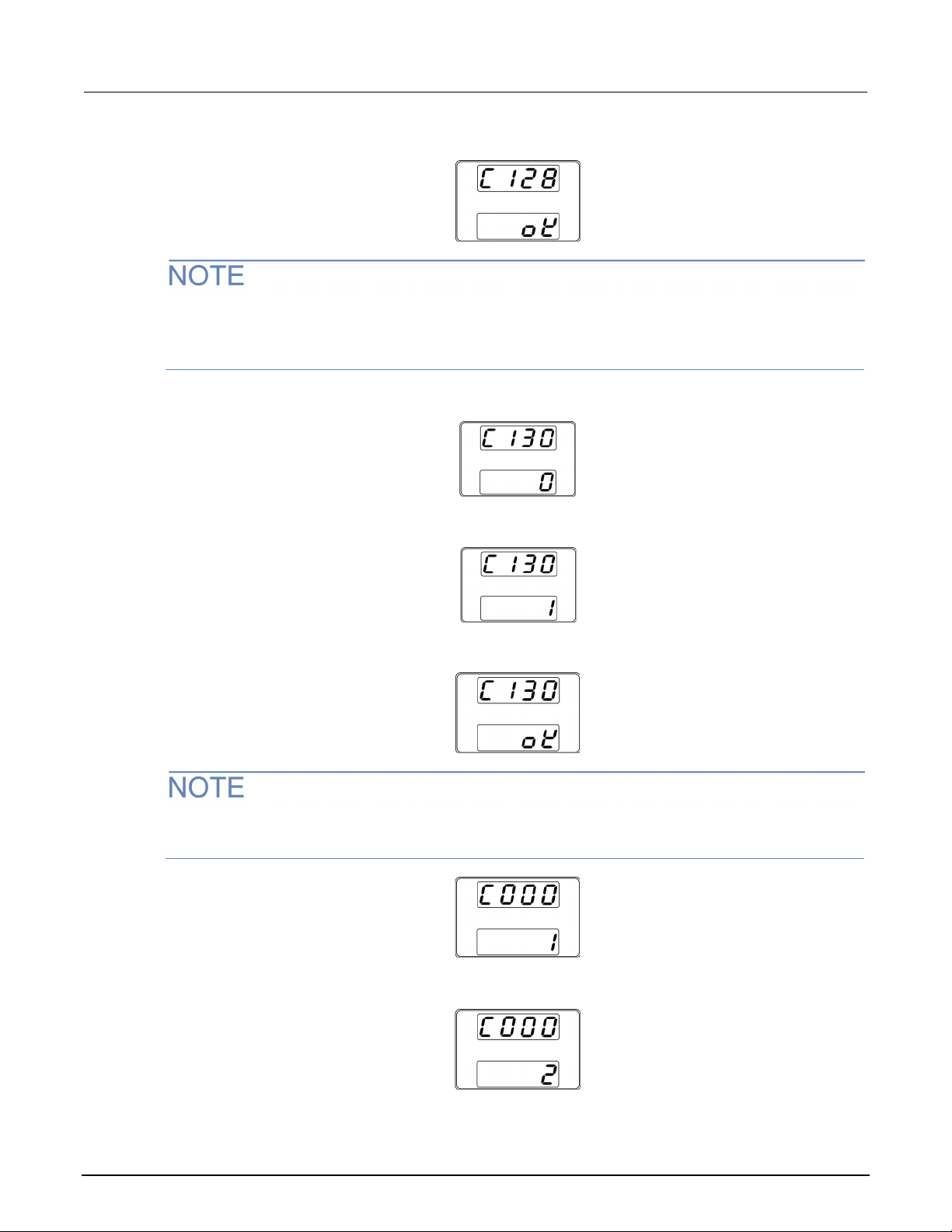
18. Press the voltage knob to start the automatic OCP adjustment (C128).
The display will indicate "OK" when the adjustment is complete. Additionally, the output turns on and
the CC indicator is lit. Also, the instrument automatically returns to C120 after the automatic OCP
adjustment ends.
19. Rotate the voltage knob to go to save mode (C130).
20. Rotate the current knob until "1" is shown on the bottom display (C130:1)
21. Press the voltage knob to save the adjustment results.
The display will indicate "OK" and the instrument will automatically return to "C000" when the
adjustment value is saved.
22. Rotate the current knob to go to "exit adjustment" mode (C000:2).
077104803 / June 2021 9-5
Page 56
Section
Verification and Adjustment Manual
9: Constant current adjustment Series 2260B Programmable Power Supplies
23. Press the voltage knob to exit adjustment mode.
The "x" in the diagram above indicates that the value is not fixed.
Constant current adjustment is complete.
9-6 077104803 / June 2021
Page 57

In this section:
Adjustment codes ................................................................... 10-1
F-01
X
Power applied; Function key lights up
F-00
0000
Enter adjustment mode
C000
0
Password entered; instrument ready for adjustment
C000
1
Enter constant voltage adjustment mode
C000
2
Exit adjustment mode
C010
- - - -
Standby to execute external voltage adjustment
C011
- - - -
Output button illuminates and CV is displayed
C020
- - - -
Standby to execute external current adjustment
C021
- - - -
Output button illuminates and CC is displayed
C030
- - - -
Exit external current adjustment
C110
- - - -
Enter voltage adjustment mode
C111
- - - -
Standby adjustment offset voltage value
C112
X
Adjustment offset voltage value
C113
- - - -
Standby adjustment half-scale voltage value
C114
X
Adjustment full-scale voltage value
C115
- - - -
Standby adjustment full-scale voltage value
C116
X
Adjustment full-scale voltage value
C117
- - - -
Standby OVP adjustment
C118
ok
OVP adjustment
C120
- - - -
Enter current adjustment mode
C121
- - - -
Standby adjustment half-scale current value
C122
X
Adjustment offset current value
C123
- - - -
Standby adjustment half-scale current value
C124
X
Adjustment half-scale current value
C125
- - - -
Adjustment full-scale current value
C126
X
Set the full-scale value
C127
- - - -
Standby OCP adjustment
C128
ok
OCP adjustment
C130
0
Save mode
C130
1
Save adjustment results
C130
ok
Indicates adjustment results saved
X X Exit adjustment mode
Adjustment codes
Voltage display Current display Description
Section 10
Adjustment code glossary
The "x" in the previous table indicates that the value is not fixed.
Page 58

All Keithley trademarks and trade names are the property of Keithley Instruments.
All other trademarks and trade names are the property of their respective companies.
Specifications are subject to change without notice.
Keithley Instruments
Corporate Headquarters • 28775 Aurora Road • Cleveland, Ohio 44139 • 440-248-0400 • 1-800-833-9200 • tek.com/keithley
07/2020
Loading...