

Series 2230 Triple-Channel Power Supplies Verification,Adjustment Manual
Table of contents
 Loading...
Tektronix Series 2230 Triple-Channel Power Supplies Verification,Adjustment Manual User manual
Page 1

Series 2230
Triple-Channel Power Supplies
Verification and Adjustment Manual
tek.com/keithley
2230-905-01 Rev. B A
pril 2022
*P2230-905-01B*
2230-905-01B
Page 2

Triple-Channel Power Supplies
Series 2230
Verification and Adjustment Manual
Page 3

© 2022, Keithley Instruments, LLC
Cleveland, Ohio, U.S.A.
All rights reserved.
Any unauthorized reproduction, photocopy, or use of the information herein, in whole or in part,
without the prior written approval of Keithley Instruments, LLC, is strictly prohibited.
These are the original instructions in English.
All Keithley Instruments product names are trademarks or registered trademarks of Keithley
Instruments, LLC. Other brand names are trademarks or registered trademarks of their respective
holders.
Microsoft, Visual C++, Excel, and Windows are either registered trademarks or trademarks of
Microsoft Corporation in the United States and/or other countries.
Document number: 2230-905-01 Rev. B April 2022
Page 4

Safety precautions
The following safety precautions should be observed before using this product and any associated instrumentation. Although
some instruments and accessories would normally be used with nonhazardous voltages, there are situations where hazardous
conditions may be present.
This product is intended for use by personnel who recognize shock hazards and are familiar with the safety precautions required
to avoid possible injury. Read and follow all installation, operation, and maintenance information carefully before using the
product. Refer to the user documentation for complete product specifications.
If the product is used in a manner not specified, the protection provided by the product warranty may be impaired.
The types of product users are:
Responsible body is the individual or group responsible for the use and maintenance of equipment, for ensuring that the
equipment is operated within its specifications and operating limits, and for ensuring that operators are adequately trained.
Operators use the product for its intended function. They must be trained in electrical safety procedures and proper use of the
instrument. They must be protected from electric shock and contact with hazardous live circuits.
Maintenance personnel perform routine procedures on the product to keep it operating properly, for example, setting the line
voltage or replacing consumable materials. Maintenance procedures are described in the user documentation. The procedures
explicitly state if the operator may perform them. Otherwise, they should be performed only by service personnel.
Service personnel are trained to work on live circuits, perform safe installations, and repair products. Only properly trained
service personnel may perform installation and service procedures.
Keithley products are designed for use with electrical signals that are measurement, control, and data I/O connections, with low
transient overvoltages, and must not be directly connected to mains voltage or to voltage sources with high transient
overvoltages. Measurement Category II (as referenced in IEC 60664) connections require protection for high transient
overvoltages often associated with local AC mains connections. Certain Keithley measuring instruments may be connected to
mains. These instruments will be marked as category II or higher.
Unless explicitly allowed in the specifications, operating manual, and instrument labels, do not connect any instrument to mains.
Exercise extreme caution when a shock hazard is present. Lethal voltage may be present on cable connector jacks or test
fixtures. The American National Standards Institute (ANSI) states that a shock hazard exists when voltage levels greater than
30 V RMS, 42.4 V peak, or 60 VDC are present. A good safety practice is to expect that hazardous voltage is present in any
unknown circuit before measuring.
Operators of this product must be protected from electric shock at all times. The responsible body must ensure that operators
are prevented access and/or insulated from every connection point. In some cases, connections must be exposed to potential
human contact. Product operators in these circumstances must be trained to protect themselves from the risk of electric shock. If
the circuit is capable of operating at or above 1000 V, no conductive part of the circuit may be exposed.
Do not connect switching cards directly to unlimited power circuits. They are intended to be used with impedance-limited
sources. NEVER connect switching cards directly to AC mains. When connecting sources to switching cards, install protective
devices to limit fault current and voltage to the card.
Before operating an instrument, ensure that the line cord is connected to a properly-grounded power receptacle. Inspect the
connecting cables, test leads, and jumpers for possible wear, cracks, or breaks before each use.
When installing equipment where access to the main power cord is restricted, such as rack mounting, a separate main input
power disconnect device must be provided in close proximity to the equipment and within easy reach of the operator.
For maximum safety, do not touch the product, test cables, or any other instruments while power is applied to the circuit under
test. ALWAYS remove power from the entire test system and discharge any capacitors before: connecting or disconnecting
cables or jumpers, installing or removing switching cards, or making internal changes, such as installing or removing jumpers.
Do not touch any object that could provide a current path to the common side of the circuit under test or power line (earth)
ground. Always make measurements with dry hands while standing on a dry, insulated surface capable of withstanding the
voltage being measured.
Page 5

For safety, instruments and accessories must be used in accordance with the operating instructions. If the instruments or
accessories are used in a manner not specified in the operating instructions, the protection provided by the equipment may be
impaired.
Do not exceed the maximum signal levels of the instruments and accessories. Maximum signal levels are defined in the
specifications and operating information and shown on the instrument panels, test fixture panels, and switching cards.
When fuses are used in a product, replace with the same type and rating for continued protection against fire hazard.
Chassis connections must only be used as shield connections for measuring circuits, NOT as protective earth (safety ground)
connections.
If you are using a test fixture, keep the lid closed while power is applied to the device under test. Safe operation requires the use
of a lid interlock.
screw is present, connect it to protective earth (safety ground) using the wire recommended in the user documentation.
If a
The
symbol on an instrument means caution, risk of hazard. The user must refer to the operating instructions located in the
user documentation in all cases where the symbol is marked on the instrument.
The symbol on an instrument means warning, risk of electric shock. Use standard safety precautions to avoid personal
contact with these voltages.
The
The
If this
symbol on an instrument shows that the surface may be hot. Avoid personal contact to prevent burns.
symbol indicates a connection terminal to the equipment frame.
symbol is on a product, it indicates that mercury is present in the display lamp. Please note that the lamp must be
properly disposed of according to federal, state, and local laws.
The WARNING heading in the user documentation explains hazards that might result in personal injury or death. Always read
the associated information very carefully before performing the indicated procedure.
The CAUTION heading in the user documentation explains hazards that could damage the instrument. Such damage may
invalidate the warranty.
The CAUTION heading with the
symbol in the user documentation explains hazards that could result in moderate or minor
injury or damage the instrument. Always read the associated information very carefully before performing the indicated
procedure. Damage to the instrument may invalidate the warranty.
Instrumentation and accessories shall not be connected to humans.
Before performing any maintenance, disconnect the line cord and all test cables.
To maintain protection from electric shock and fire, replacement components in mains circuits — including the power
transformer, test leads, and input jacks — must be purchased from Keithley. Standard fuses with applicable national safety
approvals may be used if the rating and type are the same. The detachable mains power cord provided with the instrument may
only be replaced with a similarly rated power cord. Other components that are not safety-related may be purchased from other
suppliers as long as they are equivalent to the original component (note that selected parts should be purchased only through
Keithley to maintain accuracy and functionality of the product). If you are unsure about the applicability of a replacement
component, call a Keithley office for information.
Unless otherwise noted in product-specific literature, Keithley instruments are designed to operate indoors only, in the following
environment: Altitude at or below 2,000 m (6,562 ft); temperature 0 °C to 50 °C (32 °F to 122 °F); and pollution degree 1 or 2.
To clean an instrument, use a cloth dampened with deionized water or mild, water-based cleaner. Clean the exterior of the
instrument only. Do not apply cleaner directly to the instrument or allow liquids to enter or spill on the instrument. Products that
consist of a circuit board with no case or chassis (e.g., a data acquisition board for installation into a computer) should never
require cleaning if handled according to instructions. If the board becomes contaminated and operation is affected, the board
should be returned to the factory for proper cleaning/servicing.
Safety precaution revision as of June 2018.
Page 6

Table of contents
Introduction ............................................................................................................... 1-1
Welcome .............................................................................................................................. 1-1
Introduction to this manual ................................................................................................... 1-1
Extended warranty ............................................................................................................... 1-2
Contact information .............................................................................................................. 1-2
Performance verification .......................................................................................... 2-1
Introduction .......................................................................................................................... 2-1
Factory service ..................................................................................................................... 2-2
Test record ........................................................................................................................... 2-2
2230-30-3 test report ................................................................................................................. 2-3
2230-30-6 test report ................................................................................................................. 2-8
2230-60-3 test report ............................................................................................................... 2-13
Verification test requirements ............................................................................................ 2-18
Environmental conditions ........................................................................................................ 2-18
Warmup period ........................................................................................................................ 2-18
Line power............................................................................................................................... 2-19
Recommended test equipment ............................................................................................... 2-20
Verification test procedures ............................................................................................... 2-22
Check DC voltage setting and DC voltage readback accuracy ............................................... 2-22
Check DC voltage line regulation ............................................................................................ 2-24
Check DC voltage load regulation ........................................................................................... 2-25
Check DC current and DC current readback accuracy ........................................................... 2-27
Check DC current line regulation ............................................................................................ 2-29
Check DC current load regulation ........................................................................................... 2-31
Check voltage noise (20 MHz) ................................................................................................ 2-33
Check current noise (20 MHz) ................................................................................................. 2-35
Adjustment ................................................................................................................ 3-1
Introduction .......................................................................................................................... 3-1
Environmental conditions ..................................................................................................... 3-2
Temperature and relative humidity ............................................................................................ 3-2
Line power................................................................................................................................. 3-2
Warmup period ..................................................................................................................... 3-2
Recommended test equipment ............................................................................................ 3-3
General adjustment considerations ..................................................................................... 3-3
Initial instrument setup ......................................................................................................... 3-4
Connect the calibration equipment ............................................................................................ 3-4
Connect the remote communication .......................................................................................... 3-5
Calibration adjustment procedures ...................................................................................... 3-6
Configure the serial communication interface ........................................................................... 3-7
Calibrate voltage ....................................................................................................................... 3-9
Calibrate current ...................................................................................................................... 3-10
Page 7

Contact information .................................................................. 1-2
In this section:
Welcome
Thank you for choosing a Keithley Instruments product. The Series 2230 Triple-Channel Power
Supplies (Models 2230-30-3, 2230-30-6, and 2230-60-3) provide output power up to 195 W and 375
W. Each power supply has three isolated power channels, allowing you to power circuits with different
references or polarities.
Section 1
Introduction
Welcome .................................................................................. 1-1
Introduction to this manual ....................................................... 1-1
Extended warranty ................................................................... 1-2
The Series 2230 supports remote sensing and has rear-panel connections to make automated test
more convenient. Built in RS-232 and USB interfaces allow multiple communication methods. The
Series 2230 power supplies cover a wide range of applications in a space-saving 2U half-rack size.
Introduction to this manual
This manual provides instructions to help you calibrate and adjust your Keithley Instruments 2230. In
this manual, the term "calibration" refers to the process of verifying that the accuracy of the instrument
is within its one-year accuracy specifications. The term "adjustment" refers to the process of changing
the calibration constants so that the accuracy of the instrument is within its one-year accuracy
specifications.
This manual presents calibration information, adjustment information, and command descriptions for
the calibration and adjustment commands.
For additional command descriptions, refer to the Series 2230Triple-Channel Power Supplies User's
Manual (part number 2230-905-01), which is available on the
page.
Product Support and Downloads web
Page 8

Section
Verification and Adjustment Manual
1: Introduction Series 2230 Triple-Channel Power Supplies
Extended warranty
Additional years of warranty coverage are available on many products. These valuable contracts
protect you from unbudgeted service expenses and provide additional years of protection at a fraction
of the price of a repair. Extended warranties are available on new and existing products. Contact your
local Keithley Instruments office, sales partner, or distributor for details.
Contact information
If you have any questions after you review the information in this documentation, please contact your
local Keithley Instruments office, sales partner, or distributor. You can also call the Tektronix
corporate headquarters (toll-free inside the U.S. and Canada only) at 1-800-833-9200. For worldwide
contact numbers, visit tek.com/contact
.
1-2 2230-905-01 Rev. B April 2022
Page 9

In this section:
Verification test procedures .................................................... 2-22
Introduction .............................................................................. 2-1
Factory service ......................................................................... 2-2
Test record ............................................................................... 2-2
Verification test requirements ................................................. 2-18
Introduction
Use the procedures in this section to verify that 2230 accuracy is within the limits stated in the
instrument’s one-year accuracy specifications. Specifications and characteristics are subject to
change without notice; refer to the Product Support and Downloads web page f
specifications.
Section 2
Performance verification
or the most recent
You can use these calibration verification procedures to:
• Make sure that the instrument was not damaged during shipment.
• Verify that the instrument meets factory specifications.
• Determine if adjustment is required.
• Verify that adjustment is done properly.
The information in this section is intended for qualified service personnel only, as
described by the types of product users in the Safety precautions. Do not attempt these
procedures unless you are qualified to do so. Some of these procedures may expose you to
hazardous voltages, which could cause personal injury or death. Use appropriate safety
precautions when working with hazardous voltages.
If the instrument is still under warranty and its performance is outside specified limits, please contact
your local Keithley Instruments office, sales partner, or distributor. You can also call the Tektronix
corporate headquarters (toll-free inside the U.S. and Canada only) at 1-800-833-9200. For worldwide
contact numbers, visit tek.com/contact
.
Page 10

Section
Verification and Adjustment Manual
DC voltage accuracy
DC voltage readback accuracy
DC voltage line regulation
DC voltage load regulation
DC current accuracy
DC current readback accuracy
DC current line regulation
DC current load regulation
Voltage noise at 20 MHz
Current noise at 20 MHz
2: Performance verification Series 2230 Triple-Channel Power Supplies
Factory service
To return the instrument to Keithley Instruments for repair:
1. Call the Repair Department at 1-800-408-8165 or send an email to
RMAREQUEST@tektronix.com for a Return Material Authorization (RMA) number.
2. Carefully pack the instrument in the original packing carton.
3. Write ATTENTION REPAIR DEPARTMENT and the RMA number on the shipping label.
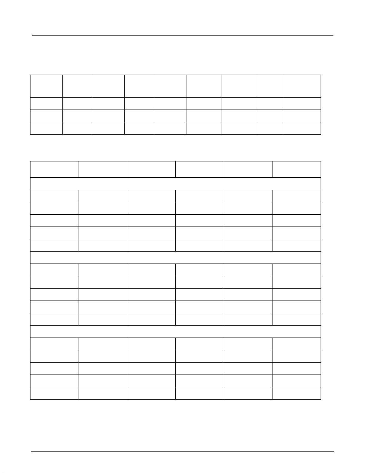
Test record
Model Serial number Procedure performed by Used as
Test Passed Failed
2-2 2230-905-01 Rev. B April 2022
Page 11

Series 2230
Performance verification
0%
0.00000 V
0.5 A
–0.01000 V
0.01000 V
25%
7.5000 V
0.5 A
7.4878 V
7.5123 V
50%
15.0000 V
0.5 A
14.9855 V
15.0145 V
75%
22.5000 V
0.5 A
22.4833 V
22.5168 V
100%
30.0000 V
0.5 A
29.9810 V
30.0190 V
0%
0.0000 V
0.5 A
–0.01000 V
0.01000 V
25%
7.5000 V
0.5 A
7.4878 V
7.5123 V
75%
22.5000 V
0.5 A
22.4833 V
22.5168 V
100%
30.0000 V
0.5 A
29.9810 V
30.0190 V
0%
0.0000 V
0.5 A
–0.01000 V
0.01000 V
25%
1.2500 V
0.5 A
1.2396 V
1.2604 V
75%
3.7500 V
0.5 A
3.7389 V
3.7611 V
100%
5.0000 V
0.5 A
4.9885 V
5.0115 V
Triple-Channel Power Supplies Verification and Adjustment Manual Section 2:
2230-30-3 test report
2230-30-3 DC voltage accuracy
Instrument test
DUT voltage Test current Minimum Measured Maximum
voltage
Channel 1
Channel 2
50% 15.0000 V 0.5 A 14.9855 V 15.0145 V
Channel 3
50% 2.5000 V 0.5 A 2.4893 V 2.5108 V
2230-905-01 Rev. B April 2022 2-3
Page 12

Section
Verification and Adjustment Manual
0%
0.00000 V
0.5 A
0.01000 V
25%
7.5000 V
0.5 A
0.01225 V
50%
15.0000 V
0.5 A
0.01450 V
75%
22.5000 V
0.5 A
0.01675 V
100%
30.0000 V
0.5 A
0.01900 V
0%
0.0000 V
0.5 A
0.01000 V
25%
7.5000 V
0.5 A
0.01225 V
50%
15.0000 V
0.5 A
0.01450 V
75%
22.5000 V
0.5 A
0.01675 V
100%
30.0000 V
0.5 A
0.01900 V
0%
0.0000 V
0.5 A
0.010000 V
25%
1.2500 V
0.5 A
0.010375 V
50%
2.5000 V
0.5 A
0.010750 V
75%
3.7500 V
0.5 A
0.011125 V
100%
5.0000 V
0.5 A
0.011500 V
0.00600 V
0.00600 V
0.00350 V
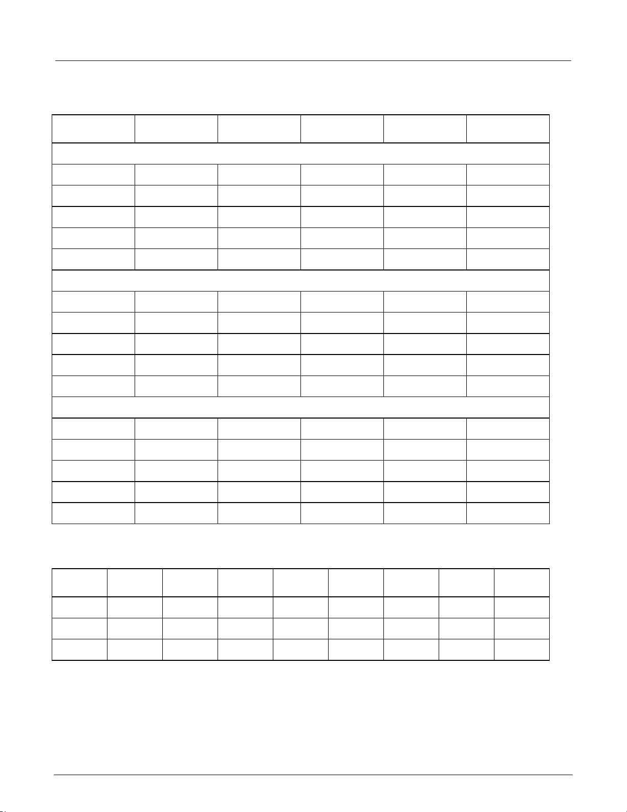
2230-30-3 DC voltage readback accuracy
2: Performance verification Series 2230 Triple-Channel Power Supplies
Instrument
test voltage
Channel 1
Channel 2
Channel 3
DUT voltage Test current Measured
voltage
Voltage
readback
Absolute
difference
Maximum
difference
2230-30-3 DC voltage line regulation
Instrument Minimum Maximum Nominal Nominal
minimum
Channel 1
Channel 2
Channel 3
2-4 2230-905-01 Rev. B April 2022
Maximum
nominal
Larger Maximum
value
Page 13
Series 2230
ance verification
0.00600 V
0.00600 V
0%
15 V
0.00000 A
–0.00500 A
0.00500 A
25%
15 V
0.75000 A
0.74425 A
0.75575 A
50%
15 V
1.50000 A
1.49350 A
1.50650 A
75%
15 V
2.25000 A
2.24275 A
2.25725 A
100%
15 V
3.00000 A
2.99200 A
3.00800 A
0%
15 V
0.00000 A
–0.00500 A
0.00500 A
25%
15 V
0.75000 A
0.74425 A
0.75575 A
50%
15 V
1.50000 A
1.49350 A
1.50650 A
75%
15 V
2.25000 A
2.24275 A
2.25725 A
0%
5 V
0.00000 A
–0.00500 A
0.00500 A
50%
5 V
1.50000 A
1.49350 A
1.50650 A
75%
5 V
2.25000 A
2.24275 A
2.25725 A
100%
5 V
3.00000 A
2.99200 A
3.00800 A
Triple-Channel Power Supplies Verification and Adjustment Manual Section 2: Perform
2230-30-3 DC voltage load regulation
Instrument Minimum Reference Maximum Reference
minimum
Channel 1
Channel 2
Channel 3
0.00350 V
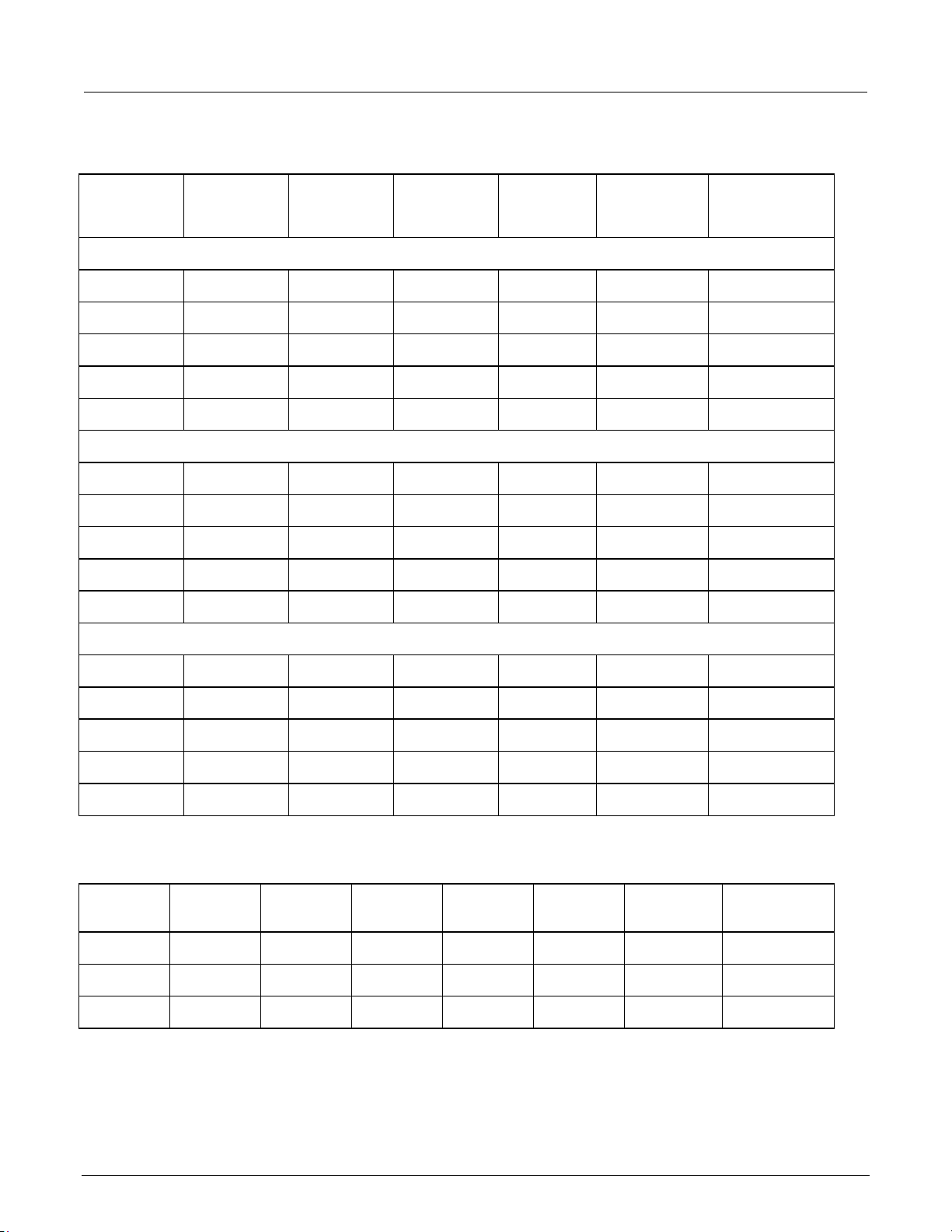
2230-30-3 DC current accuracy
Instrument test
Test voltage DUT current Minimum Measured
current
Channel 1
Maximum
reference
Maximum
reference
/0.98
current
Largest Maximum
value
Maximum
Channel 2
100% 15 V 3.00000 A 2.99200 A 3.00800 A
Channel 3
25% 5 V 0.75000 A 0.74425 A 0.75575 A
2230-905-01 Rev. B April 2022 2-5
Page 14
Section
Verification and Adjustment Manual
0%
0.00000 A
0.00500 A
25%
0.75000 A
0.00575 A
50%
1.50000 A
0.00650 A
75%
2.25000 A
0.00725 A
100%
3.00000 A
0.00800 A
0%
0.00000 A
0.00500 A
25%
0.75000 A
0.00575 A
50%
1.50000 A
0.00650 A
75%
2.25000 A
0.00725 A
100%
3.00000 A
0.00800 A
0%
0.00000 A
0.00500 A
25%
0.75000 A
0.00575 A
50%
1.50000 A
0.00650 A
75%
2.25000 A
0.00725 A
100%
3.00000 A
0.00800 A
15 V
0.00330 A
15 V
0.00330 A
5 V
0.00330 A
2230-30-3 DC current readback accuracy
2: Performance verification Series 2230 Triple-Channel Power Supplies
Instrument test
current
Channel 1
Channel 2
Channel 3
Test current Measured
current
Current readback Absolute
difference
Maximum
difference
2230-30-3 DC current line regulation
Instrument Test
voltage
Channel 1
Channel 2
Channel 3
2-6 2230-905-01 Rev. B April 2022
Minimum Maximum Nominal Nominal
minimum
Maximum
nominal
Larger Maximum
value
Page 15

Series 2230
Performance verification
0.00330 A
0.00330 A
20 Ω
1.00 mV
3.0 mV
20 Ω
1.00 mV
3.0 mV
3.3 Ω
1.00 mV
3.0 mV
1 Ω 4.0 mA
1 Ω 4.0 mA
1 Ω 4.0 mA
Triple-Channel Power Supplies Verification and Adjustment Manual Section 2:
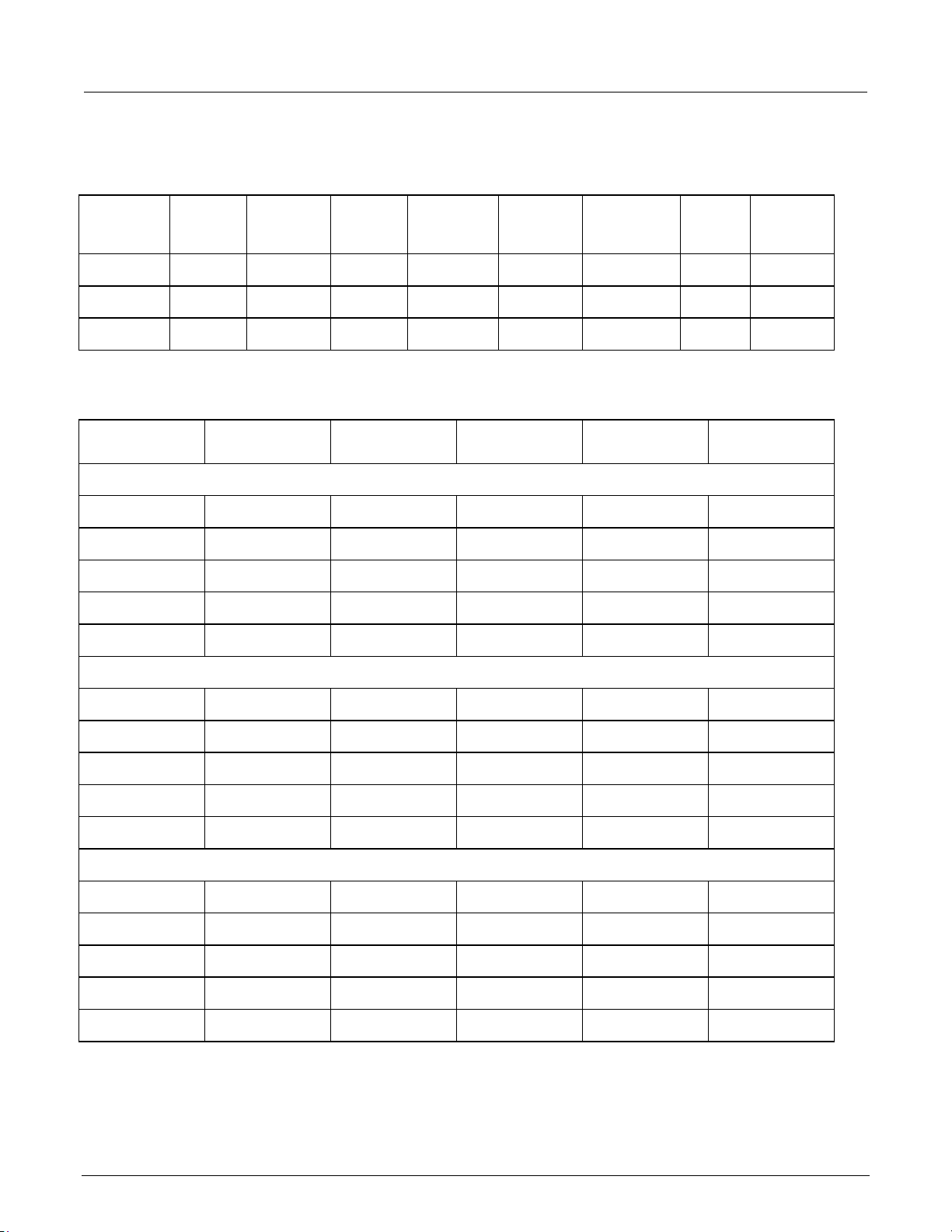
2230-30-3 DC current load regulation
Instrument Minimum Reference Maximum Reference
minimum
Maximum
reference
Larger Maximum
difference
Channel 1
Channel 2
0.00330 A
Channel 3
2230-30-3 voltage noise at 20 MHz
Instrument Voltage test load R1 Measured RMS Maximum RMS Measured pk-pk Maximum pk-pk
Channel 1
Channel 2
Channel 3
2230-30-3 current noise at 20 MHz
Instrument Current test load R1 Measured RMS Maximum RMS
Channel 1
Channel 2
Channel 3
2230-905-01 Rev. B April 2022 2-7
Page 16

Section
Verification and Adjustment Manual
0%
0.00000 V
0.5 A
–0.01000 V
0.01000 V
25%
7.5000 V
0.5 A
7.4878 V
7.5123 V
50%
15.0000 V
0.5 A
14.9855 V
15.0145 V
75%
22.5000 V
0.5 A
22.4833 V
22.5168 V
100%
30.0000 V
0.5 A
29.9810 V
30.0190 V
0%
0.0000 V
0.5 A
–0.01000 V
0.01000 V
25%
7.5000 V
0.5 A
7.4878 V
7.5123 V
75%
22.5000 V
0.5 A
22.4833 V
22.5168 V
100%
30.0000 V
0.5 A
29.9810 V
30.0190 V
0%
0.0000 V
0.5 A
–0.01000 V
0.01000 V
25%
1.2500 V
0.5 A
1.2396 V
1.2604 V
75%
3.7500 V
0.5 A
3.7389 V
3.7611 V
100%
5.0000 V
0.5 A
4.9885 V
5.0115 V
2: Performance verification Series 2230 Triple-Channel Power Supplies
2230-30-6 test report
2230-30-6 DC voltage accuracy
Instrument test
DUT voltage Test current Minimum Measured Maximum
voltage
Channel 1
Channel 2
50% 15.0000 V 0.5 A 14.9855 V 15.0145 V
Channel 3
50% 2.5000 V 0.5 A 2.4893 V 2.5108 V
2-8 2230-905-01 Rev. B April 2022
Page 17
Series 2230
Performance verification
25%
7.5000 V
0.5 A
0.01225 V
50%
15.0000 V
0.5 A
0.01450 V
100%
30.0000 V
0.5 A
0.01900 V
0%
0.0000 V
0.5 A
0.01000 V
25%
7.5000 V
0.5 A
0.01225 V
50%
15.0000 V
0.5 A
0.01450 V
75%
22.5000 V
0.5 A
0.01675 V
100%
30.0000 V
0.5 A
0.01900 V
0%
0.0000 V
0.5 A
0.010000 V
25%
1.2500 V
0.5 A
0.010375 V
50%
2.5000 V
0.5 A
0.010750 V
75%
3.7500 V
0.5 A
0.011125 V
100%
5.0000 V
0.5 A
0.011500 V
0.00600 V
0.00600 V
0.00350 V
2230-30-6 DC voltage readback accuracy
Triple-Channel Power Supplies Verification and Adjustment Manual Section 2:
Instrument
test
voltage
Channel 1
0% 0.00000 V 0.5 A 0.01000 V
75% 22.5000 V 0.5 A 0.01675 V
Channel 2
Channel 3
DUT voltage Test current Measured
voltage
Voltage
readback
Absolute
difference
Maximum
difference
2230-30-6 DC voltage line regulation
Instrument Minimum Maximum Nominal Nominal
minimum
Channel 1
Channel 2
Channel 3
2230-905-01 Rev. B April 2022 2-9
Maximum
nominal
Larger Maximum
value
Page 18
Section
Verification and Adjustment Manual
0.00600 V
0.00600 V
0%
15 V
0.00000 A
–0.00800 A
0.00800 A
25%
15 V
1.50000 A
1.49050 A
1.50950 A
50%
15 V
3.00000 A
2.98900 A
3.01100 A
75%
15 V
4.50000 A
4.48750 A
4.51250 A
0%
15 V
0.00000 A
–0.00800 A
0.00800 A
25%
15 V
1.50000 A
1.49050 A
1.50950 A
50%
15 V
3.00000 A
2.98900 A
3.01100 A
75%
15 V
4.50000 A
4.48750 A
4.51250 A
100%
15 V
6.00000 A
5.98600 A
6.01400 A
0%
5 V
0.00000 A
–0.00500 A
0.00500 A
25%
5 V
0.75000 A
0.74425 A
0.75575 A
50%
5 V
1.50000 A
1.49350 A
1.50650 A
75%
5 V
2.25000 A
2.24275 A
2.25725 A
100%
5 V
3.00000 A
2.99200 A
3.00800 A
2: Performance verification Series 2230 Triple-Channel Power Supplies
2230-30-6 DC voltage load regulation
Instrument Minimum Reference Maximum Reference
minimum
Maximum
reference
Maximum
reference
Largest Maximum
value
/0.98
Channel 1
Channel 2
Channel 3
0.00350 V
2230-30-6 DC current accuracy
Instrument test
current
Test voltage DUT current Minimum Measured
current
Maximum
Channel 1
100% 15 V 6.00000 A 5.98600 A 6.01400 A
Channel 2
Channel 3
2-10 2230-905-01 Rev. B April 2022
Page 19

Series 2230
Performance verification
0%
0.00000 A
0.0080 A
25%
1.50000 A
0.0095 A
50%
3.00000 A
0.0110 A
75%
4.50000 A
0.0125 A
100%
6.00000 A
0.0140 A
0%
0.00000 A
0.0080 A
25%
1.50000 A
0.0095 A
50%
3.00000 A
0.0110 A
75%
4.50000 A
0.0125 A
100%
6.00000 A
0.0140 A
0%
0.00000 A
0.00500 A
25%
0.75000 A
0.00575 A
50%
1.50000 A
0.00650 A
75%
2.25000 A
0.00725 A
100%
3.00000 A
0.00800 A
15 V
0.00360 A
15 V
0.00360 A
5 V
0.00330 A
2230-30-6 DC current readback accuracy
Triple-Channel Power Supplies Verification and Adjustment Manual Section 2:
Instrument test
current
Channel 1
Channel 2
Channel 3
Test current Measured
current
Current readback Absolute
difference
Maximum
difference
2230-30-6 DC current line regulation
Instrument Test
voltage
Channel 1
Channel 2
Channel 3
2230-905-01 Rev. B April 2022 2-11
Minimum Maximum Nominal Nominal
minimum
Maximum
nominal
Larger Maximum
value
Page 20

Section
Verification and Adjustment Manual
0.00360 A
0.00330 A
20 Ω
1.00 mV
4.0 mV
20 Ω
1.00 mV
4.0 mV
3.3 Ω
1.00 mV
3.0 mV
1 Ω 5.0 mA
1 Ω 5.0 mA
1 Ω 4.0 mA
2: Performance verification Series 2230 Triple-Channel Power Supplies
2230-30-6 DC current load regulation
Instrument Minimum Reference Maximum Reference
minimum
Maximum
reference
Larger Maximum
difference
Channel 1
Channel 2
0.00360 A
Channel 3
2230-30-6 voltage noise at 20 MHz
Instrument Voltage test load R1 Measured RMS Maximum RMS Measured pk-pk Maximum pk-pk
Channel 1
Channel 2
Channel 3
2230-30-6 current noise at 20 MHz
Instrument Current test load R1 Measured RMS Maximum RMS
Channel 1
Channel 2
Channel 3
2-12 2230-905-01 Rev. B April 2022
Page 21

Series 2230
Performance verification
0%
0.00000 V
0.5 A
–0.01000 V
0.01000 V
25%
15.0000 V
0.5 A
14.9855 V
15.0145 V
50%
30.0000 V
0.5 A
29.9810 V
30.0190 V
75%
45.0000 V
0.5 A
44.9765 V
45.0235 V
100%
60.0000 V
0.5 A
59.9720 V
60.0280 V
0%
0.0000 V
0.5 A
–0.01000 V
0.01000 V
25%
15.0000 V
0.5 A
14.9855 V
15.0145 V
50%
30.0000 V
0.5 A
29.9810 V
30.0190 V
100%
60.0000 V
0.5 A
59.9720 V
60.0280 V
25%
1.2500 V
0.5 A
1.2396 V
1.2604 V
50%
2.5000 V
0.5 A
2.4893 V
2.5108 V
100%
5.0000 V
0.5 A
4.9885 V
5.0115 V
Triple-Channel Power Supplies Verification and Adjustment Manual Section 2:
2230-60-3 test report
2230-60-3 DC voltage accuracy
Instrument test
DUT voltage Test current Minimum Measured Maximum
voltage
Channel 1
Channel 2
75% 45.0000 V 0.5 A 44.9765 V 45.0235 V
Channel 3
0% 0.0000 V 0.5 A –0.01000 V 0.01000 V
75% 3.7500 V 0.5 A 3.7389 V 3.7611 V
2230-905-01 Rev. B April 2022 2-13
Page 22

Section
Manual
0%
0.00000 V
0.5 A
0.0100 V
25%
15.0000 V
0.5 A
0.0145 V
50%
30.0000 V
0.5 A
0.0190 V
75%
45.0000 V
0.5 A
0.0235 V
100%
60.0000 V
0.5 A
0.0280 V
0%
0.00000 V
0.5 A
0.0100 V
25%
15.0000 V
0.5 A
0.0145 V
50%
30.0000 V
0.5 A
0.0190 V
75%
45.0000 V
0.5 A
0.0235 V
100%
60.0000 V
0.5 A
0.0280 V
0%
0.0000 V
0.5 A
0.010000 V
25%
1.2500 V
0.5 A
0.010375 V
50%
2.5000 V
0.5 A
0.010750 V
75%
3.7500 V
0.5 A
0.011125 V
100%
5.0000 V
0.5 A
0.011500 V
0.00900 V
0.00900 V
0.00350 V
2230-60-3 DC voltage readback accuracy
2: Performance verification Series 2230 Triple-Channel Power Supplies Verification and Adjustment
Instrument
test voltage
Channel 1
Channel 2
Channel 3
DUT voltage Test current Measured
voltage
Voltage
readback
Absolute
difference
Maximum
difference
2230-60-3 DC voltage line regulation
Instrument Minimum Maximum Nominal Nominal
minimum
Channel 1
Channel 2
Channel 3
2-14 2230-905-01 Rev. B April 2022
Maximum
nominal
Larger Maximum
value
Page 23

Series 2230
Performance verification
0.00900 V
0.00900 V
0%
30 V
0.00000 A
–0.00500 A
0.00500 A
25%
30 V
0.75000 A
0.74425 A
0.75575 A
50%
30 V
1.50000 A
1.49350 A
1.50650 A
75%
30 V
2.25000 A
2.24275 A
2.25725 A
100%
30 V
3.00000 A
2.99200 A
3.00800 A
0%
30 V
0.00000 A
–0.00500 A
0.00500 A
25%
30 V
0.75000 A
0.74425 A
0.75575 A
50%
30 V
1.50000 A
1.49350 A
1.50650 A
75%
30 V
2.25000 A
2.24275 A
2.25725 A
0%
5 V
0.00000 A
–0.00500 A
0.00500 A
50%
5 V
1.50000 A
1.49350 A
1.50650 A
75%
5 V
2.25000 A
2.24275 A
2.25725 A
100%
5 V
3.00000 A
2.99200 A
3.00800 A
Triple-Channel Power Supplies Verification and Adjustment Manual Section 2:
2230-60-3 DC voltage load regulation
Instrument Minimum Reference Maximum Reference
minimum
Channel 1
Channel 2
Channel 3
0.00350 V
2230-60-3 DC current accuracy
Instrument test
Test voltage DUT current Minimum Measured
current
Channel 1
Maximum
reference
Maximum
reference
/0.98
current
Largest Maximum
value
Maximum
Channel 2
100% 30 V 3.00000 A 2.99200 A 3.00800 A
Channel 3
25% 5 V 0.75000 A 0.74425 A 0.75575 A
2230-905-01 Rev. B April 2022 2-15
Page 24

Section
Verification and Adjustment Manual
0%
0.00000 A
0.00500 A
25%
0.75000 A
0.00575 A
50%
1.50000 A
0.00650 A
75%
2.25000 A
0.00725 A
100%
3.00000 A
0.00800 A
0%
0.00000 A
0.00500 A
25%
0.75000 A
0.00575 A
50%
1.50000 A
0.00650 A
75%
2.25000 A
0.00725 A
100%
3.00000 A
0.00800 A
0%
0.00000 A
0.00500 A
25%
0.75000 A
0.00575 A
50%
1.50000 A
0.00650 A
75%
2.25000 A
0.00725 A
100%
3.00000 A
0.00800 A
2: Performance verification Series 2230 Triple-Channel Power Supplies
2230-60-3 DC current readback accuracy
Instrument test
current
Channel 1
Channel 2
Channel 3
Test current Measured
current
Current
readback
Absolute
difference
Maximum
difference
2-16 2230-905-01 Rev. B April 2022
Page 25

Series 223
Performance verification
15 V
0.00330 A
5 V
0.00330 A
0.00330 A
0.00330 A
0.00330 A
40 Ω
1.00 mV
4.0 mV
40 Ω
1.00 mV
4.0 mV
1 Ω 4.0 mA
1 Ω 4.0 mA
0 Triple-Channel Power Supplies Verification and Adjustment Manual Section 2:
2230-60-3 DC current line regulation
Instrument Test
voltage
Channel 1
15 V 0.00330 A
Minimum Maximum Nominal Nominal
minimum
Maximum
nominal
Larger Maximum
value
Channel 2
Channel 3
2230-60-3 DC current load regulation
Instrument Minimum Reference Maximum Reference
minimum
Maximum
reference
Larger Maximum
difference
Channel 1
Channel 2
Channel 3
2230-60-3 voltage noise at 20 MHz
Instrument Voltage test load R1 Measured RMS Maximum RMS Measured pk-pk Maximum pk-pk
Channel 1
Channel 2
Channel 3
3.3 Ω 1.00 mV 3.0 mV
2230-60-3 current noise at 20 MHz
Instrument Current test load R1 Measured RMS Maximum RMS
Channel 1
1 Ω 4.0 mA
Channel 2
Channel 3
2230-905-01 Rev. B April 2022 2-17
Page 26

Section
ification and Adjustment Manual
2: Performance verification Series 2230 Triple-Channel Power Supplies Ver
Verification test requirements
Be sure that you perform these verification tests:
• Under the proper environmental conditions.
• After the specified warmup period.
• Using the correct line voltage.
• Using the proper test equipment.
• Using the specified output signal and reading limits.
Environmental conditions
Conduct the calibration verification procedures in a test environment with:
• An ambient temperature of 18 °C to 28 °C.
• A relative humidity of less than or equal to 80 percent, unless otherwise noted.
• No direct airflow on the input terminals.
Warmup period
Allow the 2230 to warm up for at least 30 minutes before conducting the calibration verification
procedures.
If the instrument has been subjected to temperature extremes (more than 5 °C above T
additional time for the internal temperature of the instrument to stabilize. Typically, allow an additional
hour to stabilize an instrument that is 10 °C outside the specified temperature range.
Allow the test equipment to warm up for the amount of time recommended by the manufacturer.
), allow
cal
2-18 2230-905-01 Rev. B April 2022
Page 27

Series 2230
Performance verification
Triple-Channel Power Supplies Verification and Adjustment Manual Section 2:
Line power
The 2230 requires:
• Line voltage of 99 V to 132 V for 2230-30-3, or 108 V to 132 V for 2230-30-6 and 2230-60-3
• Line frequency of 60 Hz
or
• Line voltage of 198 V to 264 V
• Line frequency of 50 Hz
Calibration verification tests should be performed within this range.
The instrument automatically senses the line frequency at power up.
2230-905-01 Rev. B April 2022 2-19
Page 28

Section
Verification and Adjustment Manual
Kikusui
PCR2000M
Variable AC output from
least 750 VA capacity
AC power source
Keithley
Instruments
2380 series
Variable DC load capable of
6 A dc and 40 V dc
Electronic load
Keithley
2000 DMM
Voltage measurement from
scalar
DC voltmeter
- - 18 AWG (minimum)
Wire lengths are not critical
High-current
22 AWG (minimum)
Wire lengths are not critical
Low-current
Guildline
9230A-50
0.050 Ω ±100 ppm at 25 W
coefficient
50 mΩ precision
Guildline
92301 cable set
Kelvin 4-terminal measuring
voltmeter
Current sense
OHMITE
15FR050E
0.050 Ω, 5 W
connector
50 mΩ resistor for
2: Performance verification Series 2230 Triple-Channel Power Supplies
Recommended test equipment
The following table describes the recommended calibration verification equipment. You can also use
other equipment if it meets specifications listed in the table below.
Manufacturer Model Description Used as
90 V ac to 265 V ac with at
Instruments
- -
12 mV to 40 V, higher than
100 ppm accuracy that can
multiply the result by a
connection wire assemblies:
#10 fork lug to #10
fork lug, quantity 2
Stackable banana to
#10 fork lug,
quantity 2
Stackable banana to
bare wire, quantity 2
connection wires:
Banana plug to
banana plug, quantity
2
Bare wire to stackable
banana, quantity 2
Bare wire to banana,
quantity 2
connection wire
connection wire
2-20 2230-905-01 Rev. B April 2022
±4 ppm/°C temperature
cables from shunt resistor to
quantity 2
Both leads of each resistor
require a banana jack
shunt resistor
resistor cabling
remote sense
testing
Page 29

Series 2230
Performance verification
- - Loading resistors for high
connect to the power supply
Load resistor for
Vishay/Dale
RH05012R00FE02
2230-60-3: 24 Ω
2230-30-6: 6 Ω
CH1
Vishay/Dale
RH05012R00FE02
2230-60-3: 24 Ω
2230-30-6: 6 Ω
CH2
Vishay/Dale
RH05012R00FE02
2.5 Ω
CH3
Vishay/Dale
HL10006Z1R000JJ
1 Ω, 100 W, 5% of tolerance
connect to the power supply
Load resistor for
Tektronix
DPO3012
20 MHz bandwidth-limited
oscilloscope at 1 mV/division
Oscilloscope
Tektronix
P2220, 1X probe
Low capacitance,
6 MHz/200 MHz
Oscilloscope probe
Tektronix
P6139A, 10X
Low capacitance, 10 MΩ,
500 MHz
Oscilloscope probe
Tektronix
012-0482-00
50 Ω BNC, male-to-male
Coaxial cable
Electronics
breakout
Triple-Channel Power Supplies Verification and Adjustment Manual Section 2:
Manufacturer Model Description Used as
current in voltage mode and
high voltage in current
mode,
All resistors should be rated
for at least 50 W, ohms
tolerance within 5%
Resistor composition is not
critical
Both leads of the load
resistor require a banana
plug/jack (or equivalent) to
2230-30-3: 12 Ω
2230-30-3: 12 Ω
Both leads of the load
resistor require a banana
plug/jack (or equivalent) to
voltage
noise testing
current
noise testing
Pomona
1 MΩ/10 MΩ, 1X/10X
3073 BNC female to banana
BNC adapter
2230-905-01 Rev. B April 2022 2-21
Page 30

Section
Verification and Adjustment Manual
connections in the following figure)
Electronic load
Low-current connection wire (fine line
connections in the following figure)
DC voltmeter
2: Performance verification Series 2230 Triple-Channel Power Supplies
Verification test procedures
Use the following procedures to perform the verification tests.
Check DC voltage setting and DC voltage readback accuracy
Equipment required Comment
AC power source High-current connection wire (bold line
To perform the test on each channel sequentially:
1. Set up the equipment as shown in the following figure.
Figure 1: Connections for checking the voltage
2-22 2230-905-01 Rev. B April 2022
Page 31

Series 2230
Performance verification
Triple-Channel Power Supplies Verification and Adjustment Manual Section 2:
Make sure that the equipment is properly warmed up.
To ensure accurate measurements, the voltmeter must be connected as close as possible to the
front panel of the device under test (DUT). It is recommended that you use fork lugs between the
electronic load and the DUT and banana plugs between the DUT and voltmeter. You can also use
fork lugs for both connections to the DUT.
2. Set the voltmeter as follows:
Set it to measure DC volts.
Set it to autorange.
Verify that the math mx+b function is disabled (select Shift + DC), ensuring that volts are
being read.
3. Set the electronic load as follows:
Set to a constant current.
Set to draw a constant current at the test current specified for the channel under test in the
table for DC voltage accuracy.
4. Set the channel under test to the full-scale output current.
5. Set the channel under test to 0% of the full-scale output voltage (0 V).
6. Turn the DUT output on.
7. Enter the voltmeter reading in the table for DC voltage accuracy.
8. Enter the voltmeter reading in the table for DC voltage readback accuracy.
9. Enter the voltage readback of the channel under test in the table for DC voltage readback
accuracy.
10. Calculate the difference between the two measurements made in steps 8 and 9 and enter the
value in the appropriate column of the table. Check whether the absolute difference is within the
maximum difference.
11. Increase the channel under test output voltage by 25% of the full-scale output voltage.
12. Repeat steps 7 through 11 until you complete testing at 100% of full scale.
This completes the check for one channel. If needed, return to step 1 to repeat the procedure for
each additional channel.
2230-905-01 Rev. B April 2022 2-23
Page 32

Section
Verification and Adjustment Manual
110
99 V
220
198 V
Channel 1
2230-30-3: 3 A
2230-60-3: 3 A
2230-60-3: 3 A
Channel 3
2230-30-3: 3 A
2230-60-3: 3 A
110
132 V
220
264 V
2: Performance verification Series 2230 Triple-Channel Power Supplies
Check DC voltage line regulation
Ensure the warm-up criteria have been met, as described in Warmup period (on page 2-18).
To perform the test on each channel sequentially:
1. Set up the equipment as shown in the figure in
Check DC voltage setting and DC voltage
readback accuracy (on page 2-22).
2. Change the AC power source output to the minimum voltage specified in the following table.
DUT voltage selector switch AC power source voltage
3. Set the voltmeter as follows:
Set to measure DC volts.
Set to autorange.
Verify that the math mx+b function is disabled (select Shift + DC), ensuring that volts are
being read.
4. Set the electronic load as follows:
Set to constant current.
Set to draw the specified test current.
Channel Test current
2230-30-6: 6 A
Channel 2 2230-30-3: 3 A
2230-30-6: 6 A
2230-30-6: 3 A
5. Set the channel under test to 100% of the full-scale output current.
6. Set the channel under test to 100% of the full-scale output voltage.
7. Turn the DUT output on.
8. Enter the voltmeter reading in the Minimum column of the table for DC voltage line regulation for
the channel under test.
9. Change the AC power source output to the maximum voltage specified in the following table.
DUT voltage selector switch AC power source voltage
2-24 2230-905-01 Rev. B April 2022
Page 33

Series 2230
Performance verification
110
115 V
220
230 V
Triple-Channel Power Supplies Verification and Adjustment Manual Section 2:
10. Enter the voltmeter reading in the Maximum column of the table for checking DC voltage line
regulation for the channel under test.
11. Change the AC power source output to match the voltage selector switch setting of the DUT.
DUT voltage selector switch AC power source voltage
12. Enter the voltmeter reading in the Nominal column of the table for checking DC voltage line
regulation for the channel under test.
13. Calculate the difference between the two values in the Nominal and Minimum columns.
14. Calculate the difference between the two values in the Nominal and Maximum columns.
15. Enter the calculated values in the appropriate columns.
16. Enter the larger of the two values calculated in steps 13 and 14 in the appropriate column.
This completes the check for one channel. If needed, repeat the procedure for each additional
channel.
Check DC voltage load regulation
Ensure the warm-up criteria have been met, as described in Warmup period (on page 2-18).
To perform the test on each channel sequentially:
1. Set up the equipment as shown in the figure in
readback accuracy (on page 2-22).
2. Set the voltmeter as follows:
Set to measure DC volts.
Set to autorange.
Verify that the math mx+b function is disabled (select Shift + DC), ensuring that volts are
being read.
3. Set the electronic load as follows:
Set to constant current.
Set to draw 0 A.
Check DC voltage setting and DC voltage
2230-905-01 Rev. B April 2022 2-25
Page 34

Section
Verification and Adjustment Manual
Channel 1
2230-30-3: 1.5 A
2230-60-3: 1.5 A
2230-60-3: 1.5 A
Channel 3
2230-30-3: 1.5 A
2230-60-3: 1.5 A
Channel 1
2230-30-3: 3 A
2230-60-3: 3 A
Channel 2
2230-30-3: 3 A
2230-60-3: 3 A
Channel 3
2230-30-3: 3 A
2230-60-3: 3 A
2: Performance verification Series 2230 Triple-Channel Power Supplies
4. Set the channel under test to 100% of the full-scale output current.
5. Set the channel under test to 100% of the full-scale output voltage.
6. Turn the DUT output on.
7. Enter the voltmeter reading in the Minimum column of the table for DC voltage load regulation for
the channel under test.
8. Increase the electronic load to the reference load test current value.
Channel Test current
2230-30-6: 3 A
Channel 2 2230-30-3: 1.5 A
2230-30-6: 3 A
2230-30-6: 1.5 A
9. Enter the voltmeter reading in the Reference column of the table for DC voltage load regulation
for the channel under test.
10. Increase the electronic load to the maximum load test current value.
Channel Test current
2230-30-6: 6 A
2230-30-6: 6 A
2230-30-6: 3 A
11. Enter the voltmeter reading in the Maximum column of the table for DC voltage load regulation for
the channel under test.
12. Calculate the three values: Ref – Min, Max – Ref, and (Max – Ref)/0.98. Enter the values in the
appropriate columns.
13. Enter the largest of the three values calculated in step 12 in the appropriate column.
This completes the verification procedure for one channel. If needed, repeat the procedure for each
additional channel.
2-26 2230-905-01 Rev. B April 2022
Page 35

Series 2230
formance verification
AC power source
High-current connection wire (bold line
connections in the following figure)
Electronic load
Low-current connection wire (fine line
connections in the following figure)
DC voltmeter
Triple-Channel Power Supplies Verification and Adjustment Manual Section 2: Per
Check DC current and DC current readback accuracy
Equipment required Comment
Ensure the warm-up criteria have been met, as described in Warmup period (on page 2-18).
To perform the test on each channel sequentially:
1. Set up the equipment as shown in the following figure.
Figure 2: Connections for checking the current
2230-905-01 Rev. B April 2022 2-27
Page 36

Section
Verification and Adjustment Manual
2: Performance verification Series 2230 Triple-Channel Power Supplies
2. Set the voltmeter as follows:
Set to measure DC volts.
Set to autorange.
Set to show amperes (instead of volts) by multiplying the voltmeter result by 20.
Select Shift + DCV (mx+b).
Use the arrow key to move the cursor to the far right until it is positioned on the ^.
Press the up range button once so that M=10.00000 is displayed.
Press the arrow key to move the cursor to the first digit and press the up range button once so that
M=20.00000 is displayed.
Press the Enter button and check that the display shows B=0.
Press the Enter button and check that the display shows UNITS.
Use the arrow keys to modify the display to show AMP.
Adjust each letter individually.
3. Set the electronic load as follows:
Set to constant voltage.
Set to the specified voltage for your channel under test.
4. Set the channel under test to 0% of the full-scale output current.
5. Set the channel under test to 100% of the full-scale output voltage.
6. Turn the DUT output on.
7. Enter the voltmeter reading in the table for DC current accuracy.
8. Enter the voltmeter reading in the table for DC current readback accuracy.
9. Enter the current readback of the channel under test in the table for DC current readback
accuracy.
10. Calculate the difference between the two measurements made in steps 8 and 9. Enter the value
in the appropriate column of the table. Check whether the absolute difference is within the
maximum difference.
11. Increase the channel under test output current by 25% of the full-scale output current.
12. Repeat steps 7 through 11 until you complete testing at 100% of the full-scale output current.
This completes the check for one channel. If needed, repeat the procedure for each additional
channel.
2-28 2230-905-01 Rev. B April 2022
Page 37

Series 2230
Performance verification
110
99 V
220
198 V
Triple-Channel Power Supplies Verification and Adjustment Manual Section 2:
Check DC current line regulation
Ensure the warm-up criteria have been met, as described in Warmup period (on page 2-18).
To perform the test on each channel sequentially:
1. Set up the equipment as shown in the figure in
Check DC current and DC current readback
accuracy (on page 2-27).
2. Change the AC power source output to the voltage specified in the following table.
DUT voltage selector switch AC power source voltage
3. Set the voltmeter as follows:
Set to measure DC volts.
Set to autorange.
Set to show amperes (instead of volts) by multiplying the voltmeter result by 20.
Select Shift + DCV (mx+b).
Use the arrow key to move the cursor to the far right until it is positioned on the ^.
Press the up range button once so that M=10.00000 is displayed.
Press the arrow key to move the cursor to the first digit and then press the up range button once so
that M=20.00000 is displayed.
Press the Enter button and check that the display shows B=0.
Press the Enter button and check that the display shows UNITS.
Use the arrow keys to modify the display to show AMP.
Adjust each letter individually.
2230-905-01 Rev. B April 2022 2-29
Page 38

Section
Verification and Adjustment Manual
110
132 V
220
264 V
110
115 V
220
230 V
2: Performance verification Series 2230 Triple-Channel Power Supplies
4. Set the electronic load as follows:
Set to constant voltage.
Set to the specified voltage for your channel under test.
5. Set the channel under test to 100% of the full-scale output voltage.
6. Set the channel under test to 100% of the full-scale output current.
7. Turn the DUT output on.
8. Enter the voltmeter reading in the Minimum column of the DC current line regulation table for the
channel under test.
9. Change the AC power source output to the voltage specified in the following table.
DUT voltage selector switch AC power source voltage
10. Enter the voltmeter reading in the Maximum column for the channel under test.
11. Change the AC power source output to the voltage specified in the following table.
DUT voltage selector switch AC power source voltage
12. Enter the voltmeter reading in the Nominal column for the channel under test.
13. Calculate the two values: Nominal – Minimum and Maximum – Nominal. Enter the values in the
appropriate columns.
14. Select the larger of the two calculations from step 13 and enter the value in the appropriate
column.
15. Turn the DUT output off.
This completes the verification procedure for one channel. If needed, repeat the procedure for each
additional channel.
2-30 2230-905-01 Rev. B April 2022
Page 39

Series 2230
Performance verification
Channel 1
2230-30-3: 3.0 V
2230-60-3: 6.0 V
Channel 2
2230-30-3: 3.0 V
2230-60-3: 6.0 V
Channel 3
2230-30-3: 0.5 V
2230-60-3: 0.5 V
Triple-Channel Power Supplies Verification and Adjustment Manual Section 2:
Check DC current load regulation
Ensure the warm-up criteria have been met, as described in Warmup period (on page 2-18).
To perform the test on each channel sequentially:
1. Set up the equipment as shown in the figure in
Check DC current and DC current readback
accuracy (on page 2-27).
2. Set the voltmeter as follows:
Set to measure DC volts.
Set to autorange.
Set to show amperes (instead of volts) by multiplying the voltmeter result by 20.
Select Shift + DCV (mx+b).
Use the arrow key to move the cursor to the far right until it is positioned on the ^.
Press the up range button once so that M=10.00000 is displayed.
Press the arrow key to move the cursor to the first digit and then press the up range button once so
that M=20.00000 is displayed.
Press the Enter button and check that the display shows B=0.
Press the Enter button and check that the display shows UNITS.
Use the arrow keys to modify the display to show AMP.
Adjust each letter individually.
3. Set the electronic load as follows:
Set to constant voltage.
Set to output the minimum test voltage level.
2230-905-01 Rev. B April 2022 2-31
Channel Minimum test voltage level
2230-30-6: 3.0 V
2230-30-6: 3.0 V
2230-30-6: 0.5 V
Page 40

Section
Verification and Adjustment Manual
Channel 1
2230-30-3: 15.0 V
2230-60-3: 30.0 V
Channel 2
2230-30-3: 15.0 V
2230-60-3: 30.0 V
Channel 3
2230-30-3: 2.5 V
2230-60-3: 2.5 V
Channel 1
2230-30-3: 29.4 V
2230-60-3: 58.8 V
2230-60-3: 58.8 V
Channel 3
2230-30-3: 4.9 V
2230-60-3: 4.9 V
2: Performance verification Series 2230 Triple-Channel Power Supplies
4. Set the channel under test to 100% of the full-scale output current for your product.
5. Set the channel under test to 100% of the full-scale output voltage for your product.
6. Turn the DUT output on.
7. Enter the voltmeter reading in the Minimum column of the DC current load regulation table.
8. Increase the electronic load to the reference test voltage level.
Channel Reference test voltage level
2230-30-6: 15.0 V
2230-30-6: 15.0 V
2230-30-6: 2.5 V
9. Enter the voltmeter reading in the Reference column table for DC current load regulation at the
reference test voltage for the channel under test.
10. Increase the electronic load to the maximum test voltage level.
Channel Maximum test voltage level
2230-30-6: 29.4 V
Channel 2 2230-30-3: 29.4 V
2230-30-6: 29.4 V
2230-30-6: 4.9 V
11. Enter the voltmeter reading in the table for DC current load regulation at the maximum voltage for
the channel under test.
12. Calculate the two values: Reference – Minimum and Maximum – Reference. Enter the values in
the appropriate columns.
13. Select the larger of the two calculated values from step 12 and enter the value in the appropriate
column.
14. Power off the DUT and test equipment.
This completes the verification procedure for one channel. If needed, repeat the procedure for each
additional channel.
2-32 2230-905-01 Rev. B April 2022
Page 41

Series 2230
Performance verification
High-current connection wire
Oscilloscope
Load resistor
Coaxial cable (BNC male-male)
Triple-Channel Power Supplies Verification and Adjustment Manual Section 2:
Check voltage noise (20 MHz)
Equipment required Comment
(bold line connections in the
following figure)
BNC female-to-banana
Ensure the warm-up criteria have been met, as described in Warmup period (on page 2-18).
To perform the test on each channel sequentially:
1. Plug the device under test (DUT) into your local line power from the mains.
2. Plug the test oscilloscope into the same mains outlet as the DUT.
Some AC power sources create large amounts of high-frequency noise on the power line that the
instrument may not fully reject. Noise directly on the mains is typically better controlled. Use the
same mains outlet for both the DUT and test oscilloscope to avoid ground loops, which may cause
noise.
2230-905-01 Rev. B April 2022 2-33
Page 42

Section
Verification and Adjustment Manual
2: Performance verification Series 2230 Triple-Channel Power Supplies
3. Power on the DUT and test oscilloscope.
4. Set up the equipment as shown in the following figure. Use the appropriate load resistor
depending on the channel being tested.
Figure 3: Connections for checking voltage noise
5. Set the oscilloscope as follows:
1 mV/division
1 MΩ input resistance
20 MHz bandwidth limit
AC coupled
Line trigger
2 ms/division
Set to measure V
pk-pk
and V
RMS
6. Set the channel under test to the 100% full-scale output voltage.
7. Set the channel under test to the 100% full-scale output current.
8. Turn the DUT output on.
Do not touch the load resistor. The load resistor may become hot enough to cause burns.
2-34 2230-905-01 Rev. B April 2022
Page 43

Series 2230
Performance verification
High-current connection wire
(bold line connections)
Oscilloscope
1 Ω load resistor
Oscilloscope 10X probe
Triple-Channel Power Supplies Verification and Adjustment Manual Section 2:
9. Enter the oscilloscope measurements in the table for voltage noise at 20 MHz.
This completes the verification procedure for one channel. If needed, repeat the procedure for each
additional channel.
Check current noise (20 MHz)
Equipment required Comment
Ensure the warm-up criteria have been met, as described in Warmup period (on page 2-18).
To perform the test on each channel sequentially:
1. Plug the device under test (DUT) into your local line power from the mains.
2. Plug the test oscilloscope into the same mains outlet as the DUT.
Some AC power sources create large amounts of high-frequency noise on the power line that the
instrument may not fully reject. Noise directly on the mains is typically better controlled. Use the
same mains outlet for both the DUT and test oscilloscope to avoid ground loops which may cause
noise.
2230-905-01 Rev. B April 2022 2-35
Page 44

Section
ment Manual
2: Performance verification Series 2230 Triple-Channel Power Supplies Verification and Adjust
3. Power on the DUT and oscilloscope.
4. Set up the equipment as shown.
Figure 4: Connections for checking current noise
5. Set up the oscilloscope as follows:
1 mV/division
1 MΩ input resistance
20 MHz bandwidth limit
AC coupled
Line trigger
2 ms/division
Set to measure V
pk-pk
and V
RMS
2-36 2230-905-01 Rev. B April 2022
Page 45

Series 2230
Performance verification
Triple-Channel Power Supplies Verification and Adjustment Manual Section 2:
6. Set the channel under test to the 100% full-scale output voltage.
7. Set the channel under test to the 100% full-scale output current.
8. Turn the DUT output on.
Do not touch the load resistor. The load resistor may become hot enough to cause burns.
9. Enter the oscilloscope measurements in the table for current noise at 20 MHz.
10. Power off the DUT and test equipment.
This completes the verification procedure for one channel. If needed, repeat the procedure for each
additional channel.
2230-905-01 Rev. B April 2022 2-37
Page 46

In this section:
Calibration adjustment procedures ........................................... 3-6
Introduction .............................................................................. 3-1
Environmental conditions ......................................................... 3-1
Warmup period ......................................................................... 3-2
Recommended test equipment ................................................ 3-3
General adjustment considerations .......................................... 3-3
Initial instrument setup ............................................................. 3-4
Introduction
This section describes the procedures to adjust the 2230 calibration.
2230 performance is specified for one year from adjustment. Adjustment should be performed at this
interval, depending on your specification requirements.
Section 3
Adjustment
Performance is also specified relative to calibration adjustment temperature (T
adjustment is performed at 23 °C ± 1 °C
The information in this section is intended for qualified service personnel only, as
described by the types of product users in the Safety precautions. Do not attempt to
perform these procedures unless you are qualified to do so. Some of these procedures may
expose you to hazardous voltages, which could cause personal injury or death. Use
appropriate safety precautions when working with hazardous voltages.
). Keithley factory
cal
Page 47

Section
Verification and Adjustment Manual
3: Adjustment Series 2230 Triple-Channel Power Supplies
Environmental conditions
To ensure accurate results, the environment must meet the following conditions.
Temperature and relative humidity
Conduct the adjustment procedures in a test environment with:
• A stable ambient temperature controlled to vary less than ±1 °C during the period of adjustment.
• Keithley Instruments recommends a calibration adjustment temperature (Tcal) of 23 ± 5 °C. If a
different nominal temperature is used, it should be noted on the calibration report.
• A relative humidity of less than or equal to 40 percent, unless otherwise noted.
• No direct airflow on the input terminals.
Line power
The Model 2230 requires a line voltage and a line frequency of 99 to 132 at 60 Hz or 198 to
264 at 50 Hz.
The instrument must be adjusted within this range.
The instrument automatically senses the line frequency at power-up.
Warmup period
Allow the Model 2230 to warm up for at least 30 minutes before conducting the adjustment
procedures.
If the instrument has been subjected to temperature extremes (more than 5 °C above T
additional time for the internal temperature of the instrument to stabilize. Typically, allow an additional
hour to stabilize an instrument that is 10 °C outside the specified temperature range.
), allow
cal
Also, allow the test equipment to warm up for the amount of time recommended by the manufacturer.
3-2 2230-905-01 Rev. B April 2022
Page 48

Series 2230
Adjustment
Keithley
2380 series
Electronic load
Keithley
2000
Voltage measurement at 12 mV
to multiply the result by a scalar
Digital multimeter
- - 18 AWG (minimum) hookup wire
High-current hookup wire (high-
illustrations)
illustrations)
Triple-Channel Power Supplies Verification and Adjustment Manual Section 3:
Recommended test equipment
The following table summarizes the recommended calibration equipment. Specified accuracy of all
functions and ranges is dependent on the precision of reference signals used during the adjustment
process. To achieve specified performance, adjustment reference uncertainties must be at least four
times smaller than the best corresponding Model 2230 one-year accuracy specification for measuring
that signal.
Manufacturer Model Description Used for:
Variable DC load capable of
6 ADC and 40 V dc
through 40 V to better than
100 ppm accuracy with the ability
assemblies
- - 22 AWG (minimum) hookup wires Low-current hookup wire (low-
Refer to the manufacturer's specifications to calculate the uncertainty, which varies for each function
and range test point.
General adjustment considerations
Model 2230 performance is sensitive to errors from thermoelectric potentials generated by test cables
and connections. Be sure to use high-quality cables and connection techniques. When changing a
connection during the adjustment process, be sure to allow time (up to five minutes) for thermal
settling.
current connections are indicated
with bold lines in the setup
current connections are indicated
with light lines in the setup
The information in this section is intended for qualified service personnel only, as described
by the types of product users in the Safety precautions. Do not attempt these procedures
unless you are qualified to do so. Some of these procedures may expose you to hazardous
voltages, which could cause personal injury or death if contacted. Use appropriate safety
precautions when working with hazardous voltages.
2230-905-01 Rev. B April 2022 3-3
Page 49

Section
Verification and Adjustment Manual
3: Adjustment Series 2230 Triple-Channel Power Supplies
Initial instrument setup
Adjust the 2230 using a remote connection through the USB interface.
For details on remote communications, refer to "Remote communications interfaces" in the Series
2230 User's Manual (part number 2230-900-01).
Connect the calibration equipment
Set up the equipment for voltage calibration as follows.
Figure 5: Adjusting voltage calibration
3-4 2230-905-01 Rev. B April 2022
Page 50

Series 2230
Adjustment
Triple-Channel Power Supplies Verification and Adjustment Manual Section 3:
Set up the equipment for current calibration as follows.
Figure 6: Adjusting current calibration
Connect the remote communication
The 2230 has an RS-232 communication interface for communication with a computer. You can use a
cable with two COM ports to connect a power supply to a computer.
You need to configure the instrument to RS-232 and its parameters for the connection. For more
information about remote communication, see "RS-232 interface" in the Series 2230 User's Manual,
part number 2230-900-01).
Figure 7: Adjustment remote communication
2230-905-01 Rev. B April 2022 3-5
Page 51

Section
Verification and Adjustment Manual
Calibration Voltage
The procedure of calibration voltage
Linked
Link to remote control
OK
Execute the calibration
Calibration Current
The procedure of calibration current
Channel Number
Select the channel before the calibration of the equipment
Config
Configure parameters under the configuration interface of a serial
communication
Restore
Revert to precalibration status
Exit
Exit the calibration software
3: Adjustment Series 2230 Triple-Channel Power Supplies
Calibration adjustment procedures
Click the 2230-HP.exe icon on the computer. The following figure is displayed.
Figure 8: Start calibration adjustment
The parameters and icons in the interface are described in the following table.
Parameter or icon Description
3-6 2230-905-01 Rev. B April 2022
Page 52

Series 2230
Adjustment
Triple-Channel Power Supplies Verification and Adjustment Manual Section 3:
Configure the serial communication interface
1. Click Config. The following figure is displayed.
Figure 9: Configure the RS-232 port
2. Enter the settings for the RS-232 port. The baud rate must agree with the settings of the power
supply.
You can set the parameters of RS-232 on the power supply by selecting Menu > User Settings >
Communication Port.
2230-905-01 Rev. B April 2022 3-7
Page 53

Section
Verification and Adjustment Manual
3: Adjustment Series 2230 Triple-Channel Power Supplies
3. Press OK. The following figure is displayed.
Figure 10: Calibration adjustment interface
4. Configure the following:
Calibration voltage for every channel
Calibration current for every channel
3-8 2230-905-01 Rev. B April 2022
Page 54

Series 2230
Adjustment
Triple-Channel Power Supplies Verification and Adjustment Manual Section 3:
Calibrate voltage
The calibration operation of each channel is executed independently, but the calibration method is the
same. The following steps provide detailed information for calibrating the voltage of channel 1:
1. Choose the channel number.
2. Select Linked. Information is displayed in the right panel as shown in the following figure.
Figure 11: Voltage calibration
When Linked is selected, the calibration of the power supply is unlocked.
3. Enter the measured voltage value under the Step2: Voltage1, then click OK to calibrate the first
voltage point.
4. Enter the measured voltage value under the Step3: Voltage2, then click OK to calibrate the
second voltage point.
5. Enter the measured voltage value under the Step4: Voltage3, then click OK to calibrate the third
voltage point.
6. Enter the measured voltage value under the Step5: Voltage4, then click OK to calibrate the
fourth voltage point.
7. The interface displays Calibrate Voltage End after calibrating the last point. Click OK and save
the calibration voltage. If you need to revert to precalibration status, select Restore.
2230-905-01 Rev. B April 2022 3-9
Page 55

Section
Verification and Adjustment Manual
3: Adjustment Series 2230 Triple-Channel Power Supplies
Calibrate current
Before calibrating current, set the load mode to CC, and the current value to 150% for the unit under
test (UUT).
The selection of current calibration points is calculated according to the following formula.
= V
I
out
DMM
/ R
shunt
Where:
• I
: The current calibration point.
out
• V
• R
: The voltage value displayed in DMM.
DMM
: The resistance of shunt.
shunt
The calibration operation of each channel is executed independently, but the calibration method is the
same. The following steps provide detailed information for calibrating the current of channel 1:
1. Choose channel number.
2. Select Link power under area Calibration Current. Information is displayed in the right panel as
hown in the following figure.
s
Figure 12: Current calibration
3-10 2230-905-01 Rev. B April 2022
Page 56

Series 2230
Adjustment
Triple-Channel Power Supplies Verification and Adjustment Manual Section 3:
3. Enter the current calibration point under the Step2: Current1, then click OK to calibrate the first
current point.
4. Enter the current calibration point under the Step3: Current2, then click OK to calibrate the
second current point.
2230-905-01 Rev. B April 2022 3-11
Page 57

All Keithley trademarks and trade names are the property of Keithley Instruments.
Specifications are subject to change without notice.
All other trademarks and trade names are the property of their respective companies.
Keithley Instruments • 28775 Aurora Road • Cleveland, Ohio 44139 • 1-800-833-9200 • tek.com/keithley
04/2022
Loading...