

Page 1

Series 2230 Triple-Channel Power Supplies
User’s Manual
2230-900-01 Rev. B April 2022
tek.com/keithley
*P2230-900-01B*
2230-900-01B
Page 2

Triple-Channel Power Supplies
Series 2230
User's Manual
Page 3

© 2022, Keithley Instruments, LLC
Cleveland, Ohio, U.S.A.
All rights reserved.
Any unauthorized reproduction, photocopy, or use of the information herein, in whole or in part,
without the prior written approval of Keithley Instruments, LLC, is strictly prohibited.
These are the original instructions in English.
All Keithley Instruments product names are trademarks or registered trademarks of Keithley
Instruments, LLC. Other brand names are trademarks or registered trademarks of their respective
holders.
The Lua 5.0 software and associated documentation files are copyright © 1994 - 2015, Lua.org,
PUC-Rio. You can access terms of license for the Lua software and associated documentation at
the Lua licensing site (https://www.lua.org/license.html).
Microsoft, Visual C++, Excel, and Windows are either registered trademarks or trademarks of
Microsoft Corporation in the United States and/or other countries.
Document number: 2230-900-01 Rev. B April 2022
Page 4

Safety precautions
The following safety precautions should be observed before using this product and any associated instrumentation. Although
some instruments and accessories would normally be used with nonhazardous voltages, there are situations where hazardous
conditions may be present.
This product is intended for use by personnel who recognize shock hazards and are familiar with the safety precautions required
to avoid possible injury. Read and follow all installation, operation, and maintenance information carefully before using the
product. Refer to the user documentation for complete product specifications.
If the product is used in a manner not specified, the protection provided by the product warranty may be impaired.
The types of product users are:
Responsible body is the individual or group responsible for the use and maintenance of equipment, for ensuring that the
equipment is operated within its specifications and operating limits, and for ensuring that operators are adequately trained.
Operators use the product for its intended function. They must be trained in electrical safety procedures and proper use of the
instrument. They must be protected from electric shock and contact with hazardous live circuits.
Maintenance personnel perform routine procedures on the product to keep it operating properly, for example, setting the line
voltage or replacing consumable materials. Maintenance procedures are described in the user documentation. The procedures
explicitly state if the operator may perform them. Otherwise, they should be performed only by service personnel.
Service personnel are trained to work on live circuits, perform safe installations, and repair products. Only properly trained
service personnel may perform installation and service procedures.
Keithley products are designed for use with electrical signals that are measurement, control, and data I/O connections, with low
transient overvoltages, and must not be directly connected to mains voltage or to voltage sources with high transient
overvoltages. Measurement Category II (as referenced in IEC 60664) connections require protection for high transient
overvoltages often associated with local AC mains connections. Certain Keithley measuring instruments may be connected to
mains. These instruments will be marked as category II or higher.
Unless explicitly allowed in the specifications, operating manual, and instrument labels, do not connect any instrument to mains.
Exercise extreme caution when a shock hazard is present. Lethal voltage may be present on cable connector jacks or test
fixtures. The American National Standards Institute (ANSI) states that a shock hazard exists when voltage levels greater than
30 V RMS, 42.4 V peak, or 60 VDC are present. A good safety practice is to expect that hazardous voltage is present in any
unknown circuit before measuring.
Operators of this product must be protected from electric shock at all times. The responsible body must ensure that operators
are prevented access and/or insulated from every connection point. In some cases, connections must be exposed to potential
human contact. Product operators in these circumstances must be trained to protect themselves from the risk of electric shock. If
the circuit is capable of operating at or above 1000 V, no conductive part of the circuit may be exposed.
Do not connect switching cards directly to unlimited power circuits. They are intended to be used with impedance-limited
sources. NEVER connect switching cards directly to AC mains. When connecting sources to switching cards, install protective
devices to limit fault current and voltage to the card.
Before operating an instrument, ensure that the line cord is connected to a properly-grounded power receptacle. Inspect the
connecting cables, test leads, and jumpers for possible wear, cracks, or breaks before each use.
When installing equipment where access to the main power cord is restricted, such as rack mounting, a separate main input
power disconnect device must be provided in close proximity to the equipment and within easy reach of the operator.
For maximum safety, do not touch the product, test cables, or any other instruments while power is applied to the circuit under
test. ALWAYS remove power from the entire test system and discharge any capacitors before: connecting or disconnecting
cables or jumpers, installing or removing switching cards, or making internal changes, such as installing or removing jumpers.
Do not touch any object that could provide a current path to the common side of the circuit under test or power line (earth)
ground. Always make measurements with dry hands while standing on a dry, insulated surface capable of withstanding the
voltage being measured.
Page 5

For safety, instruments and accessories must be used in accordance with the operating instructions. If the instruments or
accessories are used in a manner not specified in the operating instructions, the protection provided by the equipment may be
impaired.
Do not exceed the maximum signal levels of the instruments and accessories. Maximum signal levels are defined in the
specifications and operating information and shown on the instrument panels, test fixture panels, and switching cards.
When fuses are used in a product, replace with the same type and rating for continued protection against fire hazard.
Chassis connections must only be used as shield connections for measuring circuits, NOT as protective earth (safety ground)
connections.
If you are using a test fixture, keep the lid closed while power is applied to the device under test. Safe operation requires the use
of a lid interlock.
If a screw is present, connect it to protective earth (safety ground) using the wire recommended in the user documentation.
The symbol on an instrument means caution, risk of hazard. The user must refer to the operating instructions located in the
user documentation in all cases where the symbol is marked on the instrument.
The symbol on an instrument means warning, risk of electric shock. Use standard safety precautions to avoid personal
contact with these voltages.
The symbol on an instrument shows that the surface may be hot. Avoid personal contact to prevent burns.
The symbol indicates a connection terminal to the equipment frame.
If this symbol is on a product, it indicates that mercury is present in the display lamp. Please note that the lamp must be
properly disposed of according to federal, state, and local laws.
The WARNING heading in the user documentation explains hazards that might result in personal injury or death. Always read
the associated information very carefully before performing the indicated procedure.
The CAUTION heading in the user documentation explains hazards that could damage the instrument. Such damage may
invalidate the warranty.
The CAUTION heading with the symbol in the user documentation explains hazards that could result in moderate or minor
injury or damage the instrument. Always read the associated information very carefully before performing the indicated
procedure. Damage to the instrument may invalidate the warranty.
Instrumentation and accessories shall not be connected to humans.
Before performing any maintenance, disconnect the line cord and all test cables.
To maintain protection from electric shock and fire, replacement components in mains circuits — including the power
transformer, test leads, and input jacks — must be purchased from Keithley. Standard fuses with applicable national safety
approvals may be used if the rating and type are the same. The detachable mains power cord provided with the instrument may
only be replaced with a similarly rated power cord. Other components that are not safety-related may be purchased from other
suppliers as long as they are equivalent to the original component (note that selected parts should be purchased only through
Keithley to maintain accuracy and functionality of the product). If you are unsure about the applicability of a replacement
component, call a Keithley office for information.
Unless otherwise noted in product-specific literature, Keithley instruments are designed to operate indoors only, in the following
environment: Altitude at or below 2,000 m (6,562 ft); temperature 0 °C to 50 °C (32 °F to 122 °F); and pollution degree 1 or 2.
To clean an instrument, use a cloth dampened with deionized water or mild, water-based cleaner. Clean the exterior of the
instrument only. Do not apply cleaner directly to the instrument or allow liquids to enter or spill on the instrument. Products that
consist of a circuit board with no case or chassis (e.g., a data acquisition board for installation into a computer) should never
require cleaning if handled according to instructions. If the board becomes contaminated and operation is affected, the board
should be returned to the factory for proper cleaning/servicing.
Safety precaution revision as of June 2018.
Page 6

Table of contents
Introduction ............................................................................................................... 1-1
Welcome .............................................................................................................................. 1-1
Products ............................................................................................................................... 1-1
Extended warranty ............................................................................................................... 1-2
Contact information .............................................................................................................. 1-2
Key features ......................................................................................................................... 1-2
Accessories .......................................................................................................................... 1-4
Available services ................................................................................................................ 1-5
General ratings ..................................................................................................................... 1-6
Wire specifications ............................................................................................................... 1-6
Quick reference ......................................................................................................... 2-1
Front-panel overview ............................................................................................................ 2-1
Rear-panel overview ............................................................................................................ 2-2
Install the system ................................................................................................................. 2-3
Dimensions ............................................................................................................................... 2-3
Select the proper line voltage .............................................................................................. 2-5
Connect the 2230-30-3 power cord ..................................................................................... 2-6
Connect the 2230-30-6/2230-60-3 power cord .................................................................... 2-6
Turn the power supply on and off ........................................................................................ 2-7
If the power supply does not turn on .................................................................................... 2-8
Self-test procedure ............................................................................................................... 2-9
Self-test error messages ........................................................................................................... 2-9
Remote communications interfaces ..................................................................................... 2-9
USB interface .......................................................................................................................... 2-10
RS-232 interface ..................................................................................................................... 2-11
Function and features .............................................................................................. 3-1
Introduction .......................................................................................................................... 3-1
Front-panel operation ........................................................................................................... 3-1
Front-panel keypad ................................................................................................................... 3-2
Turn the 2230 output on ............................................................................................................ 3-3
Turn the 2230 output off ............................................................................................................ 3-3
Navigation wheel ....................................................................................................................... 3-4
Display indicators ...................................................................................................................... 3-4
Menu description .................................................................................................................. 3-5
Basic settings ....................................................................................................................... 3-6
Set the voltage output or voltage limit for a specific channel ..................................................... 3-6
Set the current output or current limit for a specific channel ..................................................... 3-6
Save and recall setups .............................................................................................................. 3-7
Page 7

Table of contents
User's Manual
Series 2230 Triple-Channel Power Supplies
Restore default settings ....................................................................................................... 3-8
Enable or disable channels .................................................................................................. 3-9
Set the maximum voltage..................................................................................................... 3-9
Set the output timers .......................................................................................................... 3-10
Set the key lock status ....................................................................................................... 3-10
Track .................................................................................................................................. 3-11
Combine ............................................................................................................................. 3-13
V1+V2 combination for series connections ............................................................................. 3-14
I1+I2 parallel ........................................................................................................................... 3-15
I2+I3 parallel ........................................................................................................................... 3-16
I1+I2+I3 parallel ...................................................................................................................... 3-17
Turn off channel combination .................................................................................................. 3-18
User settings ...................................................................................................................... 3-19
Restore last output state on power up ..................................................................................... 3-19
Save last ................................................................................................................................. 3-19
Key beep ................................................................................................................................. 3-20
Navigation wheel lock ............................................................................................................. 3-20
Communication port ................................................................................................................ 3-21
System information ............................................................................................................ 3-21
Check the error log .................................................................................................................. 3-21
Check the firmware version ..................................................................................................... 3-22
Check the serial number ......................................................................................................... 3-22
Overtemperature protection ............................................................................................... 3-22
Use the rear-panel terminals .............................................................................................. 3-23
Remote sense connections ..................................................................................................... 3-24
Local sense connections ......................................................................................................... 3-25
Introduction to SCPI ................................................................................................. 4-1
Standard Commands for Programmable Instruments ......................................................... 4-1
Conventions ......................................................................................................................... 4-2
Commands to use with the Series 2230 .............................................................................. 4-2
Types of SCPI messages..................................................................................................... 4-3
Command execution rules ................................................................................................... 4-4
Case sensitivity .................................................................................................................... 4-4
Long-form and short-form versions ...................................................................................... 4-4
The message unit ................................................................................................................. 4-5
Headers .................................................................................................................................... 4-5
Queries ..................................................................................................................................... 4-5
Message unit separator ............................................................................................................. 4-6
Root specifier ............................................................................................................................ 4-6
Message terminator .................................................................................................................. 4-7
Multiple commands in a message ........................................................................................ 4-8
Movement in the subsystem...................................................................................................... 4-8
Including common commands ............................................................................................. 4-9
Page 8

Series 2230
of contents
Triple-Channel Power Supplies User's Manual Table
SCPI data formats ................................................................................................................ 4-9
Talking and listening data formats ............................................................................................. 4-9
Suffixes and multipliers ........................................................................................................... 4-10
Response messages .......................................................................................................... 4-10
Response data types .............................................................................................................. 4-10
Getting a response message .................................................................................................. 4-10
Multiple response messages ................................................................................................... 4-11
Response message terminator (RMT) .................................................................................... 4-11
Message exchange protocol ................................................................................................... 4-11
SCPI command completion ............................................................................................... 4-12
Using device clear .............................................................................................................. 4-12
Default setup ...................................................................................................................... 4-13
SCPI command reference ......................................................................................... 5-1
Series 2230 commands ....................................................................................................... 5-1
Common commands ............................................................................................................ 5-1
*CLS (no query form) ................................................................................................................ 5-3
*ESE ......................................................................................................................................... 5-4
*ESR? (query only) ................................................................................................................... 5-5
*IDN? (query only) ..................................................................................................................... 5-6
*OPC ......................................................................................................................................... 5-7
*PSC ......................................................................................................................................... 5-8
*RCL (no query form) ................................................................................................................ 5-9
*RST (no query form) .............................................................................................................. 5-10
*SAV (no query form) .............................................................................................................. 5-10
*SRE ....................................................................................................................................... 5-11
*STB? (query only) .................................................................................................................. 5-12
*TST? (query only) .................................................................................................................. 5-12
*WAI ........................................................................................................................................ 5-13
CALibration subsystem ...................................................................................................... 5-14
CALibrate:CLEar ..................................................................................................................... 5-14
CALibrate:CURRent[:DATA] ................................................................................................... 5-14
CALibrate:CURRent:LEVel ..................................................................................................... 5-15
CALibrate:INITital .................................................................................................................... 5-16
CALibrate:SAVe ...................................................................................................................... 5-16
CALibrate:SECure[:STATe]..................................................................................................... 5-17
CALibrate:STRing ................................................................................................................... 5-18
CALibrate:VOLTage[:DATA] ................................................................................................... 5-18
CALibrate:VOLTage:LEVel ..................................................................................................... 5-19
INSTrument subsystem...................................................................................................... 5-20
INSTrument:COMBine? .......................................................................................................... 5-20
INSTrument:COMBine:OFF .................................................................................................... 5-21
INSTrument:COMBine:PARallel .............................................................................................. 5-22
INSTrument:COMBine:SERies ............................................................................................... 5-23
INSTrument:COMBine:TRACk ................................................................................................ 5-23
INSTrument:NSELect .............................................................................................................. 5-24
INSTrument[:SELect] .............................................................................................................. 5-25
MEASurement subsystem.................................................................................................. 5-26
FETCh[:SCALar]:CURRent[:DC]? ........................................................................................... 5-26
FETCh[:SCALar]:POWer[:DC]? .............................................................................................. 5-27
FETCh[:SCALar][:VOLTage][:DC]? ......................................................................................... 5-28
MEASure[:SCALar]:CURRent[:DC]? ....................................................................................... 5-29
Page 9

Table of contents
User's Manual
Series 2230 Triple-Channel Power Supplies
MEASure[:SCALar]:POWer[:DC]? .......................................................................................... 5-30
MEASure[:SCALar][:VOLTage][:DC]? ..................................................................................... 5-31
SOURce subsystem ........................................................................................................... 5-32
[SOURce:]APPLy .................................................................................................................... 5-32
[SOURce:]CHANnel:OUTPut[:STATe] .................................................................................... 5-33
[SOURce:]CURRent[:LEVel]:DOWN[:IMMediate][:AMPLitude] ............................................... 5-34
[SOURce:]CURRent[:LEVel][:IMMediate][:AMPLitude] ........................................................... 5-35
[SOURce:]CURRent[:LEVel][:IMMediate]:STEP[:INCRement]................................................ 5-36
[SOURce:]CURRent[:LEVel]:UP[:IMMediate][:AMPLitude] ..................................................... 5-37
[SOURce:]OUTPut:ENABle..................................................................................................... 5-38
[SOURce:]OUTPut:PARallel[:STATe] ..................................................................................... 5-39
[SOURce:]OUTPut:PROTection:CLEar .................................................................................. 5-40
[SOURce:]OUTPut:SERies[:STATe] ....................................................................................... 5-41
[SOURce:]OUTPut[:STATe][:ALL] ........................................................................................... 5-42
[SOURce:]OUTPut:TIMer:DELay ............................................................................................ 5-43
[SOURce:]OUTPut:TIMer[:STATe] .......................................................................................... 5-44
[SOURce:]VOLTage[:LEVel]:DOWN[:IMMediate][:AMPLitude] ............................................... 5-45
[SOURce:]VOLTage[:LEVel][:IMMediate][:AMPLitude] ........................................................... 5-46
[SOURce:]VOLTage[:LEVel][:IMMediate]:STEP[:INCRement]................................................ 5-47
[SOURce:]VOLTage[:LEVel]:UP[:IMMediate][:AMPLitude] ..................................................... 5-48
[SOURce:]VOLTage:LIMit[:LEVel] .......................................................................................... 5-49
[SOURce:]VOLTage:LIMit:STATe ........................................................................................... 5-50
STATus subsystem ............................................................................................................ 5-51
STATus:OPERation:CONDition? ............................................................................................ 5-51
STATus:OPERation:ENABle ................................................................................................... 5-52
STATus:OPERation[:EVENt]? ................................................................................................. 5-53
STATus:OPERation:INSTrument:ENABle .............................................................................. 5-54
STATus:OPERation:INSTrument[:EVENt]? ............................................................................ 5-55
STATus:OPERation:INSTrument:ISUMmary<X>:CONDition?................................................ 5-56
STATus:OPERation:INSTrument:ISUMmary<X>:ENABle ...................................................... 5-57
STATus:OPERation:INSTrument:ISUMmary<X>[:EVENt]? .................................................... 5-58
STATus:PRESet ..................................................................................................................... 5-59
STATus:QUEStionable:CONDition? ....................................................................................... 5-60
STATus:QUEStionable:ENABle .............................................................................................. 5-61
STATus:QUEStionable[:EVENt]? ............................................................................................ 5-62
STATus:QUEStionable:INSTrument:ENABle .......................................................................... 5-63
STATus:QUEStionable:INSTrument[:EVENt]?........................................................................ 5-64
STATus:QUEStionable:INSTrument:ISUMmary<X>:CONDition? ........................................... 5-65
STATus:QUEStionable:INSTrument:ISUMmary<X>:ENABle ................................................. 5-66
STATus:QUEStionable:INSTrument:ISUMmary<X>[:EVENt]? ............................................... 5-67
Status register ........................................................................................................... 6-1
Error descriptions ..................................................................................................... 7-1
SYSTem subsystem ........................................................................................................... 5-68
SYSTem:BEEPer .................................................................................................................... 5-68
SYSTem:ERRor? .................................................................................................................... 5-69
SYSTem:LOCal ....................................................................................................................... 5-70
SYSTem:REMote .................................................................................................................... 5-71
SYSTem:RWLock[:STATe] ..................................................................................................... 5-72
SYSTem:VERSion? ................................................................................................................ 5-73
Status register overview ....................................................................................................... 6-1
Error information .................................................................................................................. 7-1
Page 10

Wire specifications ....................................................................1-6
2230-30-3
Triple-Channel Power Supplies, 2 channels: 30 V, 3 A, 1 channel:
5 V, 3 A, 195 W
2230-30-6
Triple-Channel Power Supplies, 2 channels: 30 V, 6 A, 1 channel:
5 V, 3 A, 375 W
2230-60-3
Triple-Channel Power Supplies, 2 channels: 60 V, 3 A, 1 channel:
5 V, 3 A, 375 W
Section 1
Introduction
In this section:
Welcome ...................................................................................1-1
Products ....................................................................................1-1
Extended warranty ....................................................................1-2
Contact information ...................................................................1-2
Key features ..............................................................................1-2
Accessories ...............................................................................1-4
Available services .....................................................................1-5
General ratings .........................................................................1-6
Welcome
Thank you for choosing a Keithley Instruments product. The Series 2230 Triple-Channel Power
Supplies (Models 2230-30-3, 2230-30-6, and 2230-60-3) provide output power up to 195 W and
375 W. Each power supply has three isolated power channels, allowing you to power circuits with
different references or polarities.
The Series 2230 supports remote sensing and has rear-panel connections to make automated test
more convenient. Built-in RS-232 and USB interfaces allow multiple communication methods. The
Series 2230 power supplies cover a wide range of applications in a space-saving 2U half-rack size.
Products
This manual contains information about the models listed in the following table.
Model Description
Page 11

Section
1: Introduction Series 2230 Triple-Channel Power Supplies
User's Manual
CH1
30 V
3 A
CH2
30 V
3 A
CH3
5 V
3 A
CH1
30 V
6 A
CH2
30 V
6 A
CH3
5 V
3 A
CH1
60 V
3 A
CH2
60 V
3 A
CH3
5 V
3 A
Extended warranty
Additional years of warranty coverage are available on many products. These valuable contracts
protect you from unbudgeted service expenses and provide additional years of protection at a fraction
of the price of a repair. Extended warranties are available on new and existing products. Contact your
local Keithley Instruments office, sales partner, or distributor for details.
Contact information
If you have any questions after you review the information in this documentation, please contact your
local Keithley Instruments office, sales partner, or distributor. You can also call the Tektronix
corporate headquarters (toll-free inside the U.S. and Canada only) at 1-800-833-9200. For worldwide
contact numbers, visit tek.com/contact (tek.com/en/contact-tek
Key features
).
The Series 2230 has the following features:
• Power output up to 195 W or 375 W in a space-saving 2U high, half-rack wide enclosure
• Three programmable isolated channels
• Remote sensing for maximum output accuracy in automated test
• Rear-panel connectors for convenient wiring of a test system in a rack
• Built-in RS-232 and USB communication interfaces
• 0.03 percent basic voltage accuracy
• 0.1 percent basic current accuracy
• Less than 4 mV peak-to-peak ripple and noise
Model Channel Voltage Current
2230-30-3
2230-30-6
2230-60-3
1-2 2230-900-01 Rev. B April 2022
Page 12
Section
1: Introduction Series 2230 Triple-Channel Power Supplies
User's Manual
Calibration report
0011655XX
USB cable
1746841XX
2230G-HRM Harmonic Reduction Module
0162140XX
15-terminal mating connector with three sense-source
connectors
1161283XX
Calibration report
0011655XX
USB cable
1746841XX
15-terminal mating connector with three sense-source
connectors
1161283XX
Universal rack mount kit
4299-7
Accessories
The following items are standard accessories that are included with your Series 2230-30-6 or 223060-3 order.
Accessory Part number
Line cord 1747172XX
The following items are standard accessories that are included with your Series 2230-30-3 order.
Accessory Part number
The following items are optional accessories that may be included with your Series 2230 order.
Accessory Part number
You will also get one of the following power cords.
1-4 2230-900-01 Rev. B April 2022
Page 13

Series 2230
Triple-Channel Power Supplies User's Manual Section 1:
Introduction
Option A0
North America and South America. The factory sets the line-voltage selector switch
to 110 V.
Option A1
Universal Euro. The factory sets the line-voltage selector switch to 220 V.
Option A2
United Kingdom. The factory sets the line-voltage selector switch to 220 V.
Option A3
Australia. The factory sets the line-voltage selector switch to 220 V.
Option A4
Chile, Italy. The factory sets the line-voltage selector switch to 220 V.
Option A5
Switzerland. The factory sets the line-voltage selector switch to 220 V.
Option A7
Denmark. The factory sets the line-voltage selector switch to 220 V.
Option A8
Israel. The factory sets the line-voltage selector switch to 220 V.
Option A9
Argentina. The factory sets the line-voltage selector switch to 220 V.
China.
Option A11
India. The factory sets the line-voltage selector switch to 220 V.
Option A13
Macao, Pakistan, Africa. The factory sets the line-voltage selector switch to 220 V.
Option E1
Europe bundle: United Kingdom, mainland Europe, and Switzerland.
The factory sets the line-voltage selector switch to 220 V.
Option Description
Option A10
The factory sets the line-voltage selector switch to 220 V.
Available services
For the most recent list of available services and accessories, upgrades, and options for your
instrument, visit tek.com/keithley (tek.com/en/products/keithley).
2230-900-01 Rev. B April 2022 1-5
Page 14
Section
1: Introduction Series 2230 Triple-Channel Power Supplies
User's Manual
Maximum current: 10 A
Floating voltage
Up to 400 V (DC + peak AC) between protective earth (safety ground)
and any output terminal
Operating altitude
Maximum 2000 m (6562 ft ) above sea level
Environmental conditions
For indoor use only
Installation category: II
Maximum current (A)
40
25
20
13
10 7 5
3.5
2.5
1.7
General ratings
The Series 2230 general ratings and connections are listed in the following table.
Category Specification
Power supply 2230-30-3 AC power input level:
110 to 120 V ac: 99 V ac to 132 V ac
220 to 240 V ac:198 V ac to 264 V ac
50 Hz or 60 Hz
2230G-30-6/2230G-60-3 AC power input level:
120 VAC: 108 V ac to 132 V ac
220 to 240 V ac: 198 V ac to 264 V ac
50 Hz or 60 Hz
Maximum power consumption:
2230-30-3: 700 VA
2230-30-6, 2230-60-3: 1000 VA
Wire specifications
Operating: 0 °C to 40 °C, full accuracy with maximum 80% relative
humidity at up to 40 °C, noncondensing
Storage: –20 °C to 70 °C, 10% to 85% relative humidity at up to
40 °C and 5% to 60% relative humidity above 40 °C up to 70 °C
Pollution degree: 2
Refer to the table below for the maximum current allowed for the various gauges of copper wire.
AWG wire gauge 10 12 14 16 18 20 22 24 26 28
The t
able above lists current carrying capacity of a single wire at working temperature of 30 °C. The
in this table conform with the American Wire Gauge (AWG) standard and are provided for
values
reference only.
1-6 2230-900-01 Rev. B April 2022
Page 15

Remote communications interfaces ..........................................2-9
Section 2
Quick reference
In this section:
Front-panel overview ................................................................2-1
Rear-panel overview .................................................................2-2
Install the system ......................................................................2-3
Select the proper line voltage....................................................2-5
Connect the 2230-30-3 power cord ...........................................2-6
Connect the 2230-30-6/2230-60-3 power cord .........................2-6
Turn the power supply on and off ..............................................2-7
If the power supply does not turn on .........................................2-8
Self-test procedure ....................................................................2-9
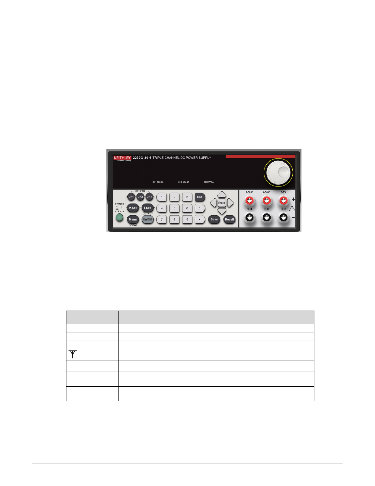
Front-panel overview
All of the Series 2230 power supplies have the same front panel. The Model 2230-30-6 is shown in
the figure below; descriptions of the numbered items follow the figure.
Figure 1: Series 2230 front panel
Page 16

Section
2: Quick reference Series 2230 Triple-Channel Power Supplies
User's Manual
1
Vacuum fluorescent display (VFD)
2
Navigation wheel
3
Output terminals
4
Up, down, left, and right arrow keys; Enter, Save, and Recall function keys
5
Numeric keypad and Esc key
6
Function keys: Channel SELECT (CH1, CH2, CH3), voltage setting (V-Set), current setting
(I-Set), Menu, and OUTPUT On/Off keys
Number Description
7 Power On/Off switch
Rear-panel overview
All of the Series 2230 power supplies have the same rear panel. The rear panel is shown in the figure
below; descriptions of the numbered items follow the figure.
Figure 2: Series 2230 rear panel
2-2 2230-900-01 Rev. B April 2022
Page 17
Serie
s 2230 Triple-Channel Power Supplies User's Manual Section 2:
Quick reference
1
Vent
2
RS-232 communication interface
3
USB communication interface
4
AC power input socket (including fuse)
5
Remote sense terminals and the output terminals
Number Description
Install the system
When you receive your Series 2230 instrument, verify that you have received all of the items listed in
Standard accessories (on page 1-4) and any other accessories that you ordered.
Do not lift or hold the instrument by the front bezel or any other protruding parts. If you do,
you may damage the instrument.
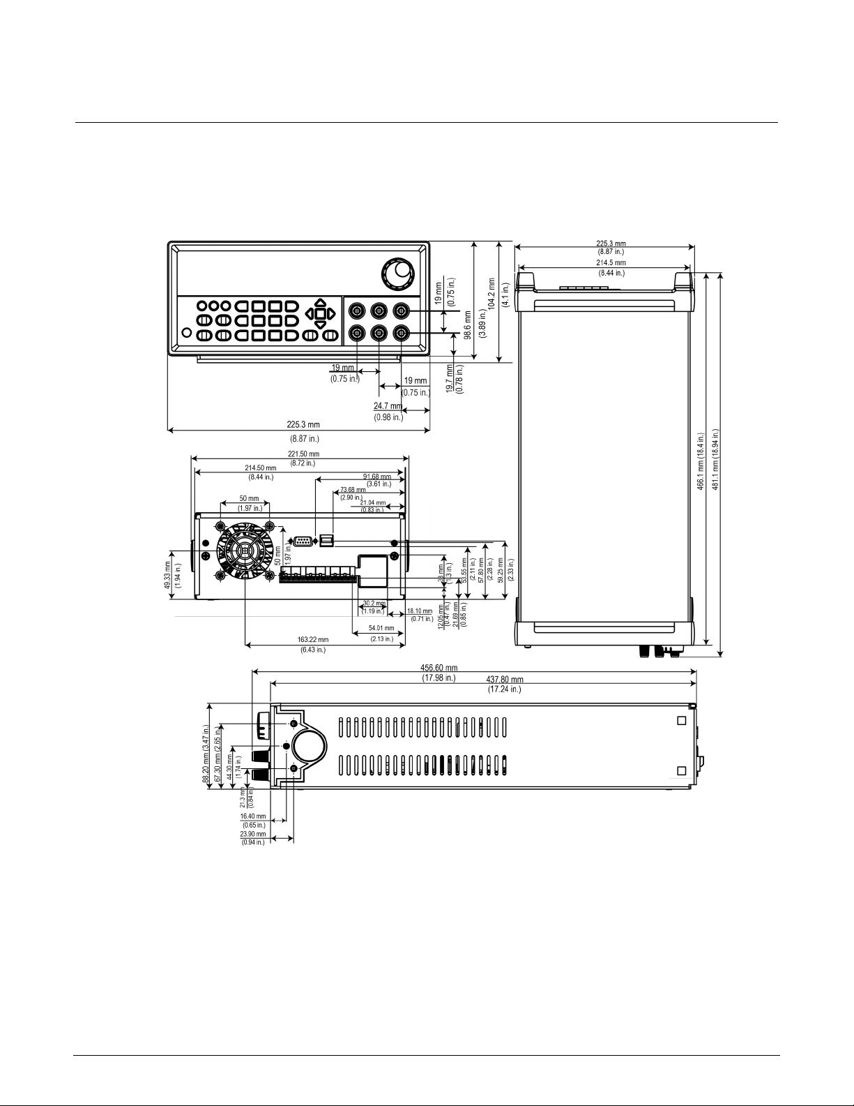
Dimensions
The dimensions of a Series 2230 power supply with no bumpers are:
• Width: 214.50 mm (8.44 in.)
• Height: 88.20 mm (3.47 in.)
• Depth: 456.60 mm (17.98 in.)
2230-900-01 Rev. B April 2022 2-3
Page 18
Section
2: Quick reference Series 2230 Triple-Channel Power Supplies
User's Manual
The following figure shows more detailed measurements for the Series 2230.
Figure 3: Series 2230 dimensions
2-4 2230-900-01 Rev. B April 2022
Page 19

Series 2230
Triple-Channel Power Supplies User's Manual Section 2:
Quick reference
Select the proper line voltage
Series 2230 power supplies have two line voltage ratings:
• 110 V to 120 V for 2230-30-3 or 120 V for 2230-30-6 and 2230-60-3
• 220 V to 240 V
Select a proper line voltage according to the voltage of your facility. You can use the line selector
switch on the bottom of the instrument to select the right voltage.
The voltage ranges of the two line voltage ratings are:
• 110 V ac to 120 V ac: 99 VAC to 132 VAC (2230-30-3) or 120 VAC:108 VAC to 132 VAC
(2230-30-6 or 2230-60-3)
• 220 V ac to 240 V ac: 198 VAC to 264 VAC
The power cord supplied with the Series 2230 power supply contains a separate protective earth
(safety ground) wire for use with grounded outlets. When proper connections are made, the
instrument chassis is connected to ground through the ground wire.
In addition, there is a ground terminal for each channel on the rear panel. When a channel is
enabled, its ground terminal should be connected to a protective earth. In the event of a failure, not
using a properly grounded protective earth and grounded outlet may result in personal injury or death
due to electric shock.
Do not replace detachable mains supply cords with inadequately rated cords. Failure to use properly
ed cords may result in personal injury or death due to electric shock.
rat
When using the model 2230-30-6 or 2230-60-3 in a country that is a member of the European Union,
you need to use the 2230-HRM inductor box in-line with the mains power cord to comply with
European Union regulations. If you use the inductor, the functions of the instrument are not affected.
2230-900-01 Rev. B April 2022 2-5
Page 20
Section
2: Quick reference Series 2230 Triple-Channel Power Supplies
User's Manual
Connect the 2230-30-3 power cord
To connect the power cord:
1. Make sure that the front-panel power switch is in the OFF position.
2. Properly set the 110 V/220 V selector switch located on the bottom of the instrument.
3. Connect the female end of the supplied power cord to the AC receptacle on the rear panel.
4. Connect the plug of the power cord to a grounded AC outlet.
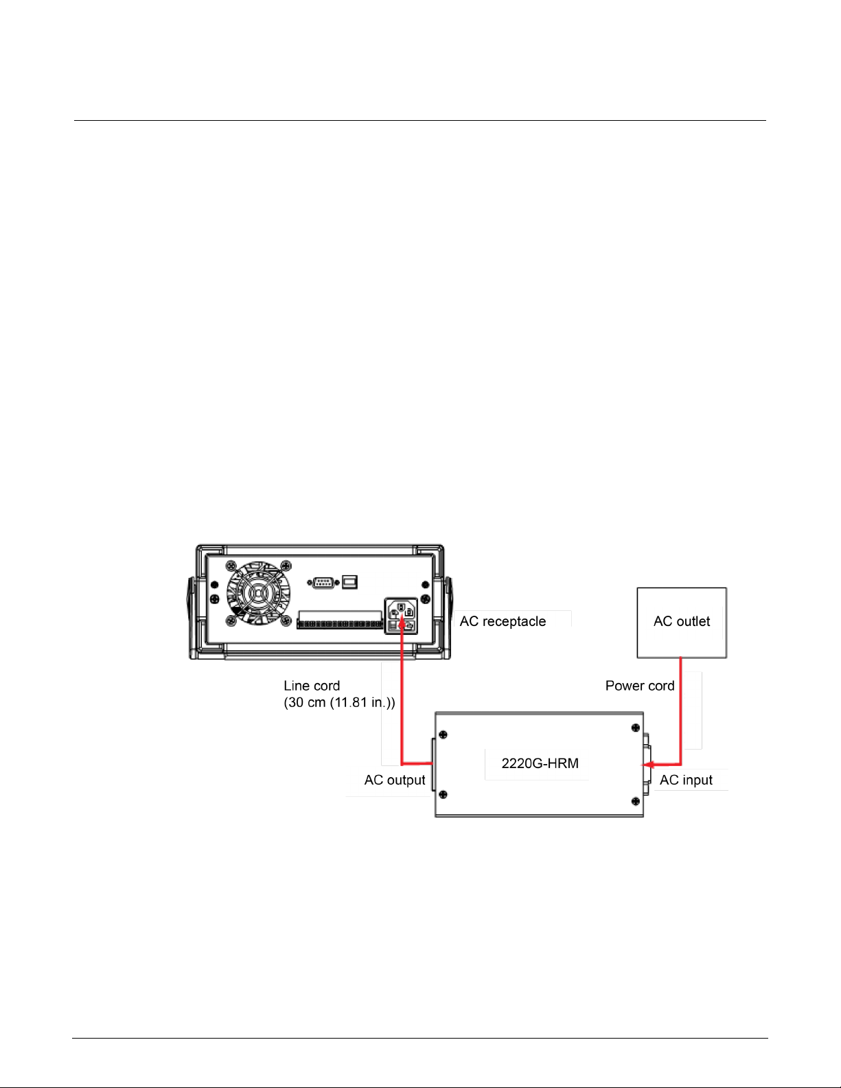
Connect the 2230-30-6/2230-60-3 power cord
When using the 2230-30-6 or 2230-60-3 in a country that is a member of the European Union, you
must use the 2230G-HRM inductor box in-line with the mains power cord to comply with European
Union regulations, as shown in the following diagram.
Figure 4: Connecting the power cord for 2230-30-6 or 2230-60-3
2-6 2230-900-01 Rev. B April 2022
Page 21

Series 2230
Triple-Channel Power Supplies User's Manual Section 2:
Quick reference
To connect the power cord:
1. Make sure that the front-panel power switch is in the OFF position.
2. Properly set the 110 V/220 V selector switch located on the bottom of the instrument.
3. Connect the female end of the supplied line cord (30 cm (11.81 in.)) to the AC receptacle on th
r
ear panel.
4. Connect the other end of the supplied line cord to the AC output of the 2230G-HRM inductor.
5. Connect the female end of the supplied power cord to the AC input of the 2230G-HRM inductor.
6. Connect the plug of the power cord to a grounded AC outlet.
Turn the power supply on and off
To turn the power supply on and off
1. Disconnect any devices under test (DUTs) from the Series 2230 before turning the instrument on.
2. To turn your instrument on, press the front-panel power switch to put it in the ON position. T
display screen illuminates.
3. To turn your instrument off, press the front-panel power switch to put it in the OFF position.
To avoid fire or electric shock, ensure that the AC input voltage fluctuation does not exceed the
range of the selected AC line voltage rating.
e
he
Make sure that wire sizes are sufficient to ensure safety in the case of short circuit and full load test.
See Wire specifications (on page 1-6
) for wire size guidelines.
2230-900-01 Rev. B April 2022 2-7
Page 22
Section
2: Quick reference Series 2230 Triple-Channel Power Supplies
User's Manual
2380-500-15
1.25 AT (115 V ac)
0.5 AT (230 V ac)
2380J-500-15
1.25 AT (100 V ac)
0.5 AT (220 V ac)
2380-120-60
1.25 AT (115 V ac)
0.5 AT (230 V ac)
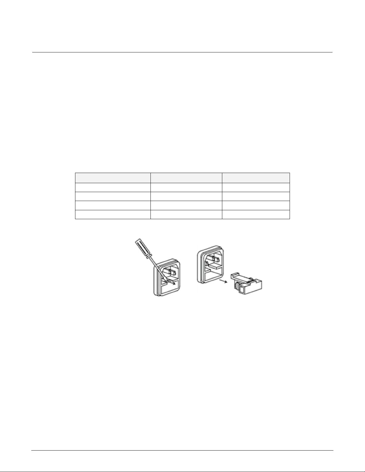
If the power supply does not turn on
To troubleshoot a power-on failure:
1. Verify that the AC power cord is firmly plugged into the power connector on the rear-panel of t
he
Series 2230.
2. Make sure that the AC power source you plugged the power supply into is energized, and th
urn the Series 2230 on.
t
en
3. Make sure the voltage selector switch is set according to the local voltage (110 VAC or 220 VAC).
Change the voltage setting if it is incorrect.
4. Verify that the correct power-line fuse is installed and functioning. If the fuse is damaged, replace
it with a fuse appropriate for your model of power supply (see the following table and graphic).
Model number Fuse specification Fuse specification
2380J-120-60 1.25 AT (100 V ac) 0.5 AT (220 V ac)
Figure 5: Model 2380 fuse compartment
2-8 2230-900-01 Rev. B April 2022
Page 23

Series 2230
Triple-Channel Power Supplies User's Manual Section 2:
Quick reference
EEPROM Test Failure
The EEPROM is damaged.
User Data Lost
The latest operation state of the power supply is lost.
Channel Initialization Failed
A channel failed to respond to inbound data.
Calibration Data Lost
Calibration data cannot be read.
Factory Calibration Data Lost
The factory calibration data in EEPROM is lost.
Self-test procedure
The Series 2230 runs a self-test automatically when it is turned on.
When the Series 2230 is turned on, the display shows the software version number (for example,
BOIS Ver. 1.XX). After approximately one second, the system starts the self-test and the display
shows Initializing….
If the self-test finishes with no errors, the display shows the set voltage value of all three channels on
the first line and the set current value of all three channels on the second line, in the format shown
below.
0.000V 0.000V 0.000V
SV0.000A SV0.000A SV0.000A
Self-test error messages
If an error occurs during the self-test, an error message is displayed. The following table lists the error
messages you might see.
Error message Meaning
Remote communications interfaces
The Series 2230 power supplies have two communication interfaces: Universal serial bus (USB) and
RS-232 interface.
2230-900-01 Rev. B April 2022 2-9
Page 24

Section
2: Quick reference Series 2230 Triple-Channel Power Supplies User's
Manual
USB interface
All power supply functions are programmable over the Series 2230G USB interface. The interface is
USB 2.0 and USBTMC-compliant.
The interface accepts REN_CONTROL, GO_TO_LOCAL, and LOCAL_LOCKOUT requests. It also accepts
the MsgID = TRIGGER USBTMC command and forwards TRIGGER requests to the function layer.
The USB interface of the Series 2230G:
• Understands all mandatory SCPI commands
• Is SR1, RL1, and DT1 capable.
To use the USB interface:
1. Press the Menu key.
2. Use the arrow keys to select User settings.
3. Press Enter. The screen displays Output Recall.
4. Press the down arrow keys to select Communication Port.
5. Press Enter.
6. Use the arrow keys to select USB (default).
7. Press Enter.
8. Press Esc to exit the menu.
If you switch to the front-panel control, all remote commands sent through the USB interface will be
invalid. If you want to continue to use the remote commands, you need to send the SYSTem:REMote
command or restart the USB interface using the VISA software.
2-10 2230-900-01 Rev. B April 2022
Page 25

Series 2230
Triple-Channel Power Supplies User's Manual Section 2:
Quick reference
RS-232 interface
You can connect a computer to your Series 2230 RS-232 port using a cable with two COM
connectors.
Please ensure the computer and power supply have the same configuration for the following items:
• Baud rate: 4800, 9600, 19200, 38400, 57600, or 115200.You can enter the system menu to set
the baud rate.
• Data bit: 8
• Stop bit: 1
• Parity bit: (none, even, odd)
none: 8 data bits that have no parity
even: 8 data bits that have even parity
odd: 8 data bits that have odd parity
For example:
Parity = None Start bit 8 data bits Stop bit
2230-900-01 Rev. B April 2022 2-11
Page 26

Section
2: Quick reference Series 2230 Triple-Channel Power Supplies
User's Manual
To use the RS-232 interface:
1. Make sure the connection from the Series 2230 to the computer is firmly inserted in the port.
2. Press the Menu key.
3. Use the arrow keys to select User settings.
4. Press Enter. The screen displays Output Recall.
5. Press the down arrow keys to select Communication Port.
6. Press Enter.
7. Use the arrow keys to select RS232.
8. Select the baud rate from the following options:
4800
9600
19200
38400
57600
115200
9. Select the parity from the following the options:
None
Even
Odd
10. Press Enter to confirm your selection.
2-12 2230-900-01 Rev. B April 2022
Page 27

Use the rear-panel terminals ...................................................3-23
Section 3
Function and features
In this section:
Introduction ...............................................................................3-1
Front-panel operation ................... Error! Bookmark not defined.
Menu description .......................................................................3-5
Basic settings ............................................................................3-6
Restore default settings ............................................................3-8
Enable or disable channels .......................................................3-9
Set the maximum voltage..........................................................3-9
Set the output timers ...............................................................3-10
Set the key lock status ............................................................3-10
Track .......................................................................................3-11
Combine..................................................................................3-13
User settings ...........................................................................3-19
System information .................................................................3-21
Overtemperature protection ....................................................3-22
Introduction
This section contains detailed descriptions of the functions and features of the Series 2230 power
supply.
Front-panel operation
After the power supply is powered on, the display shows the voltage and current settings of each
channel. When these settings are displayed, you can connect the DUT to the power supply and set
the parameters. Ensure that OUTPUT On/Off key is set to the Off state before connecting the DUT
and setting the parameters. After finishing the setup, set OUTPUT On/Off key to the On state and
start the measurement.
You can use the navigation wheel to increase or decrease a value or to scroll through the menus after
pressing the Menu key.
The display shows the operating status of each channel. When a channel operates in constant
voltage mode, the CV indicator is displayed. When it operates in the constant current mode, the CC
indicator is displayed.
Page 28
Section
3: Function and features Series 2230 Triple-Channel Power Supplies
User's Manual
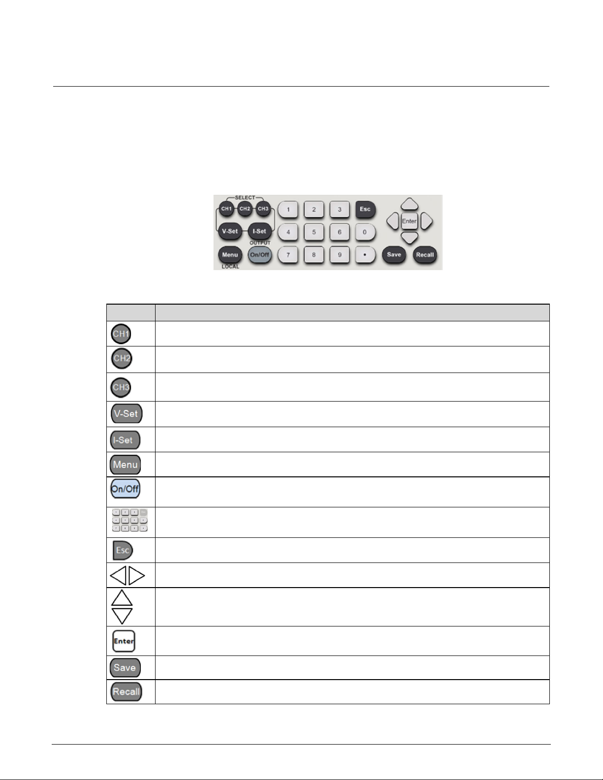
Select channel 1.
Select channel 2.
Select channel 3.
Set the voltage limit.
Set the current limit.
Open the menu to access various Series 2230 settings.
Turn the output of all enabled channels on or off. When you turn on the output, the CC or CV
Enter numbers for settings values.
Return to the previous menu level.
Use left and right arrow keys to move the cursor.
Use up and down arrow keys to adjust the parameters or select the menu operation.
Select the menu item or confirm an operation.
Save the present settings as a saved setup. The Series 2230 supports up to 36 saved setups.
Front-panel keypad
You can use the front-panel keys to control the Series 2230. Descriptions of what the keys do follow
the figure below.
Figure 6: Front-panel keypad
Key Description
indicator is visible on the display.
Return the instrument to the specified setup.
3-2 2230-900-01 Rev. B April 2022
Page 29

Serie
s 2230 Triple-Channel Power Supplies User's Manual Section 3:
Function and features
Turn the 2230 output on
You can turn the 2230 output on from the front panel or by sending remote commands.
To turn the output on using the front panel, press the OUTPUT On/Off button. The instrument is in
the output-on state when the switch is illuminated.
To turn the output on using SCPI commands, send the command:
:OUTPut:STATe ON
When you are using a remote interface to control the instrument and the output is turned off,
pressing the OUTPUT On/Off button will not turn the output on. However, if the output is turned on,
you can press the OUTPUT On/Off button to turn the output off.
Turn the 2230 output off
Turning the 2230G output off does not place the instrument in a safe state. Hazardous
voltages may be present on all output and guard terminals. To prevent electrical shock that
could cause injury or death, never make or break connections to the 2230G while the
instrument is powered on. Turn off the equipment from the front panel or disconnect the main
power cord from the rear of the 2230G before handling cables. Putting the equipment into an
output-off state does not guarantee that the outputs are powered off if a hardware or software
fault occurs.
To turn the output off using the front panel, press the OUTPUT On/Off button. The instrument is in
the output-off state when the button is not illuminated.
To turn the output off using SCPI commands, send the command:
:OUTPut[:STATe] OFF
2230-900-01 Rev. B April 2022 3-3
Page 30
Section
3: Function and features Series 2230 Triple-Channel Power Supplies
User's Manual
CC
Constant current mode
CV
Constant voltage mode
SV
Setting mode, programmed voltage and current settings are displayed
The power supply is in remote control mode
Series
The outputs of channel 1 and channel 2 are wired in series
Para
The outputs of channel 1 and channel 2 are wired in parallel
T
Tracking mode is enabled
Navigation wheel
You can use the navigation wheel to adjust voltage and current values or select the menu operation.
The navigation wheel is identified in the Front-panel overview.
Rotate the navigation wheel (shown circled in the following figure) clockwise to increase the value
and counterclockwise to decrease the value.
Figure 7: Navigation wheel
Turn the navigation wheel to scroll through the menus after pressing the Menu key. When you have
selected the menu item or value you want, press the Enter key to save your setting.
Display indicators
Indicators on the front panel of the Series 2230 indicate the present state of the instrument. The
following table describes these indicators.
Indicator Meaning
3-4 2230-900-01 Rev. B April 2022
Page 31

Series 2230
Triple-Channel Power Supplies User's Manual Section 3:
Function and features
Default Set
Restores the factory default settings.
Enable Channels
Enable/Disable CH1
Enables or disables channel 1.
Enable/Disable CH2
Enables or disables channel 2.
Enable/Disable CH3
Enables or disables channel 3.
Protection Settings
Sets the maximum voltage for each channel. This setting affects the voltage
range setting.
Sets the output timers for each channel. Once the timer expires, the output of
the specified channel is turned off.
Locks the keyboard (except the output On/Off key, left and right arrow keys,
Key Lock prevents any adjustments to channel output parameters.
Track
Track Off (default)
Disables the tracking mode.
Track CH1/CH2
Sets CH1 and CH2 to tracking mode.
Track CH2/CH3
Sets CH2 and CH3 to tracking mode.
Track ALL
Sets CH1, CH2, and CH3 to tracking mode.
Combine
Combine Off (default)
Disables the series or parallel operation mode.
V1+V2 Series
Sets CH1 and CH2 to series operation mode.
I1+I2 Parallel
Sets CH1 and CH2 to parallel operation mode.
I2+I3 Parallel
Sets CH2 and CH3 to parallel operation mode.
ALL Parallel
Sets CH1, CH2, and CH3 to parallel operation mode.
User Settings
Output Recall
Sets the output state after the Series 2230 is turned on.
Sets the voltage, current, and maximum voltage values after the Series 2230
is turned on.
Key Beep
Turns the key beeper on or off.
Knob Lock
Locks the navigation wheel (knob).
RS-232: Sets the communication interface to RS-232. You can select the
Even parity, or Odd parity).
Menu description
You can use the front-panel Menu key to access many of the Series 2230 settings. The following
table describes the settings available from the menu. Additional details about each setting are
available later in this section.
Menu items Description
Max Volt Set
Output Timers
Key Lock
Menu items Description
Save Last
Channel SELECT (CH1, CH2, CH3), V-Set, I-Set and POWER keys function)
with a password to avoid improper operation.
Communication Port
2230-900-01 Rev. B April 2022 3-5
baud rate (4800, 9600, 19200, 38400, 57600, or 115200) and parity (None,
USB (default): Sets the communication interface to USB.
Page 32

Section
3: Function and features Series 2230 Triple-Channel Power Supplies User'
s Manual
System Info
Error Log
Lists all errors that occurred.
Main:0.01/Aux:1.06
Displays the firmware version.
0123456789AF
Displays the serial number.
Menu items Description
Basic settings
The following topics describe how to set up and use the Series 2230.
Set the voltage output or voltage limit for a specific channel
You can set the voltage limit from 0 V to the maximum voltage specified for your Series 2230.
To set the voltage limit:
1. Select the channel by pressing the CH1, CH2, or CH3 key.
2. Press the V-Set key.
3. Use the numeric keys, the navigation wheel, or the up, down, right, and left arrow keys to set the
voltage limit.
4. Press the Enter key to confirm the setting.
Set the current output or current limit for a specific channel
You can set the current limit from 0 A to the maximum current specified for your Series 2230.
To set the current limit:
1. Select the channel by pressing the CH1, CH2, or CH3 key.
2. Press the I-Set key.
3. Use the numeric keys, the navigation wheel, or the up, down, right, and left arrow keys to set the
current limit.
4. Press Enter to confirm the setting.
3-6 2230-900-01 Rev. B April 2022
Page 33

Series 2230
Triple-Channel Power Supplies User's Manual Section 3:
Function and features
Save and recall setups
You can store up to 36 different setups in Series 2230 memory. Each setup includes a voltage limit,
current limit, and maximum output voltage for each channel.
To save the setups:
1. After you set up the Series 2230, press the Save key.
2. Use the number keys, the navigation wheel, or the arrow keys to select the setup memory (1 t
36) that you want to store the values in.
3. Press Enter to confirm your setting.
To recall the setups:
1. Press the Recall key.
2. Use the number keys, the navigation wheel, or the arrow keys to select the setup that you want t
ecall.
r
3. Press Enter.
You can also use the following SCPI commands to save or recall the setup:
*SAV
*RCL
The Series 2230 does not support the save and recall functions when the channels are in tracking
mode or
when they are wired in series or parallel.
o
o
2230-900-01 Rev. B April 2022 3-7
Page 34

Section
3: Function and features Series 2230 Triple-Channel Power Supplies
User's Manual
Enable CH1
Enable CH2
Enable CH3
Max V CH1
Off
Max V CH2
Off
Max V CH3
Off
Timer CH1
Off
Timer CH2
Off
Timer CH3
Off
Track
Track off
Combine
Combine off
Output Recall
Off
Save Last
On
Key beep
Off
Knob Lock
Off
Communication Port
USB
Restore default settings
To restore the factory default settings:
1. Remove all of the leads from the output terminals.
2. Press the Power key to turn on the power supply.
3. Press Menu.
4. Press Enter to select Default Set.
5. Press the down arrow key to select Yes.
6. Press Enter. The display shows Defaults Restored!. The default settings for the menu
selections are shown in the following table.
Menu selection Default setting
Enable Channels
3-8 2230-900-01 Rev. B April 2022
Page 35

Series 2230
Triple-Channel Power Supplies User's Manual Section 3:
Function and features
Enable or disable channels
You can enable or disable each output channel using the menu settings. If a channel is disabled, it
remains off when the OUTPUT On/Off key is pressed. The default setting has all the channels
enabled.
To enable or disable a channel:
1. Press the Menu key.
2. Press the down arrow key to select Enable Channels
3. P
ress Enter to confirm the setting.
4. Press the down arrow key to select Channel and press Enter.
5. Press the down arrow key to select Disable CH1 or Enable CH1 (default).
6. Press Enter.
Set the maximum voltage
You can set the maximum voltage for each channel to avoid accidental overvoltage output and
protect sensitive loads from damage.
To set the maximum voltage:
1. Press the Menu key.
2. Press the down arrow key to select Protection Settings.
3. Press Enter. The Max Volt Set indicator is displayed.
4. Press Enter. A list of maximum voltage settings for each channel is displayed.
5. Use the up and down arrow keys to select the correct channel and press Enter to confirm.
6. Press the down arrow key to select On.
.
7. Use the numeric keys, the up and down arrow keys, or the navigation wheel to adjust the voltag
alue. The value must be less than the rated voltage of the power supply.
v
8. Press Enter.
9. Press the Esc key to exit the menu.
2230-900-01 Rev. B April 2022 3-9
e
Page 36

Section
3: Function and features Series 2230 Triple-Channel Power Supplies
User's Manual
Set the output timers
You can set the amount of time that the output stays on for each channel. When the OUTPUT On/Off
key is pressed, the timers start and the output is turned on. When each active timer expires, its
corresponding channel output turns off. The timer range is from 0.1 seconds to 99999.9 seconds.
To set the output timers:
1. Press the Menu key.
2. Press the down arrow key to select Protection Settings and press Enter.
3. Press the down arrow key to select Output Timers and press Enter.
4. Use the up and down arrow keys to select the correct channel and press Enter to confirm.
5. Press the down arrow key to select On and press Enter.
6. Use the numeric keys, the up and down arrow keys, or the navigation wheel to adjust the timer.
7. Press Enter.
8. Press the Esc key to exit the menu.
Set the key lock status
You can set the key lock status for each channel in the Protection Settings menu. This function
prevents any adjustments from being made to the instrument. Once the lock is activated, a four-digit,
user-specified password must be entered to change any instrument settings. After the front panel is
locked, only the OUTPUT On/Off key, left and right arrow keys, Channel SELECT (CH1, CH2, CH3),
V-Set, I-Set, and POWER keys function. However, changes to settings cannot be made unless th
sword is entered. Turning the power off deactivates the lock and resets the password.
pas
To set the key lock status:
1. Press the Menu key.
2. Press the down arrow key to select Protection Settings.
3. Press Enter.
4. Press the down arrow key to select Key Lock and press Enter.
5. Use numeric keys to input a four-digit password and press Enter.
e
3-10 2230-900-01 Rev. B April 2022
Page 37

Series 2230
Function and features
Track
Triple-Channel Power Supplies User's Manual Section 3:
You can set channel 1 (CH1) and channel 2 (CH2), CH2 and channel 3 (CH3), and all three channels
to tracking mode. When CH1/CH2 tracking is on, channel 1 and channel 2 respond relative to one
another when adjustments in voltage are made. A constant ratio is maintained between the voltage
settings on the two channels.
The voltage ratio is set between channel 1 and channel 2 when CH1/CH2 tracking is turned on. For
example, if channel 1 and channel 2 are both set to 1 V when tracking is turned on, a one-to-one ratio
is maintained and any voltage change on channel 1 results in a corresponding change on channel 2.
If channel 1 is set to 10 V and channel 2 is set to 5 V when tracking is turned on, a two to one ratio is
maintained and any voltage change on channel 1 results in a voltage change of half the size of
channel 2.
To set up CH1/CH2 tracking mode:
1. Press the CH1 key.
2. Press the V-Set key and enter the voltage value for channel 1. For example, set the voltage of
channel 1 to 3 V.
3. Press the Enter key.
4. Press the CH2 key.
5. Press the V-Set key and enter a voltage in the ratio you want for channel 2. For example, set t
v
oltage of channel 2 to 6 V. The ratio is 2.
6. Press the Enter key.
7. Press the Menu key, and using the down arrow key, navigate to Track, and then press the Enter
key.
8. Press the down arrow key to select Track CH1/CH2 and then press the Enter key to turn
racking.
t
9. Verify that T is displayed between the voltage readings of channel 1 and channel 2 on the
display. This indicates that the power supply is in tracking mode.
he
on
2230-900-01 Rev. B April 2022 3-11
Page 38

Section
3: Function and features Series 2230 Triple-Channel Power Supplies
User's Manual
To set up CH2/CH3 tracking mode:
1. Press the CH2 key.
2. Press the V-Set key and enter the voltage value for channel 2. For example, set the voltage of
channel 2 to 3 V.
3. Press the Enter key.
4. Press the CH3 key.
5. Press the V-Set key and enter a voltage in the ratio you want for channel 3. For example, set t
he
voltage of channel 3 to 6 V. The ratio is 2.
6. Press the Enter key.
7. Press the Menu key, and using the down arrow key, navigate to Track, and then press the Enter
key.
8. Press the down arrow key to select Track CH2/CH3 and then press the Enter key to turn on
t
racking.
9. Verify that T is displayed between the voltage readings of channel 2 and channel 3 on t
splay. This indicates that the power supply is in tracking mode.
di
he
To set up CH1/CH2/CH3 tracking mode:
1. Press the CH1 key.
2. Press the V-Set key and enter the voltage value for channel 1. For example, set the voltage of
channel 1 to 1 V.
3. Press the CH2 key.
4. Press the V-Set key and enter the voltage value for channel 2. For example, set the voltage of
channel 2 to 1 V. The ratio between channel 1 and channel 2 is 1.
5. Press the Enter key.
6. Press the CH3 key.
7. Press the V-Set key and enter a voltage in the ratio you want for channel 3. For example, set t
he
voltage of channel 3 to 2 V. The ratio between channel 1 and channel 3 is 2, and the ratio
ween channel 2 and channel 3 is 2.
bet
8. Press the Enter key.
9. Press the Menu key, and using the down arrow key, navigate to Track, and then press the Enter
key.
10. Press the down arrow key to select Track ALL and then press the Enter key to turn on tracking.
11. Verify that T is displayed among the voltage readings of channel 1, channel 2, and channel 3 o
he display. This indicates that the power supply is in tracking mode.
t
3-12 2230-900-01 Rev. B April 2022
n
Page 39

Series 2230
Triple-Channel Power Supplies User's Manual Section 3:
Function and features
To disable tracking mode:
1. Press the Menu key.
2. Use the arrow keys to select Track.
3. Press the Enter key.
4. Use the arrow keys to select Track Off (default).
5. Press Enter.
If the voltage or current is set to 0, the tracking setting is ignored.
f tracking is enabled and channel 1 (CH1) and channel 2 (CH2) timers are set, the timer uses the
I
smaller set value.
Combine
You can combine the outputs of the channels. You can only set CH1 and CH2 of model 2230-30-3
and 2230-30-6 to series operation mode. You can set CH1 and CH2, CH2 and CH3, or all three
channels of 2230 to parallel operation mode. The following procedures show you how to combine
channels when outputs are wired in series or in parallel.
Do not set CH1 and CH2 of the 2230-60-3 to
60-3 to output the voltages of V1 and V2 combined, which exceeds the safe voltage of 60
dc.S
etting CH1 and CH2 to series operation may expose you to hazardous voltages that, i
ontacted, could cause personal injury or death.
c
series operation mode. This will cause the 2230-
V
f
2230-900-01 Rev. B April 2022 3-13
Page 40

Section
3: Function and features Series 2230 Triple-Channel Power Supplies
User's Manual
V1+V2 combination for series connections
You can connect two Series 2230-30 terminals in series and display the combined output voltage
value on channel 1. You cannot safely connect all three channels in series.
Model 2230G-30-3 and
not combine CH1, CH2, and CH3. This will cause the instrument to output the voltages of V1,
V2, and V3 combined, which exceeds the safe voltage of 60 VDC. Setting CH1, CH2, and CH3
to series operation may expose you to hazardous voltages, that if contacted, could cause
personal injury or death.
The wiring between the power supply output terminals affects the accuracy of measurements in this
mode. Make sure that wire sizes are sufficient, wires are short, and connections are tightened to
ensure maximum accuracy. See Wire specifications (on page 1-6) for wire size guidelines.
To combine channel 1 and channel 2 when the outputs are connected in series:
1. Connect the outputs in series, as shown in the following figure.
2230G-30-6 only support combining CH1 and CH2 in series mode. Do
Figure 8: Outputs wired in series
3-14 2230-900-01 Rev. B April 2022
Page 41

Series 2230
Triple-Channel Power Supplies User's Manual Section 3:
Function and features
2. Press the Menu key.
3. Use the arrow keys to select Combine.
4. Press the Enter key.
5. Press the down arrow key to select V1+V2 Series.
6. Press the Enter key. The screen returns to meter mode. Verify that the Series indicator is
displayed, replacing the channel 2 voltage and current readings. This indicates that the power
supply is in the V1+V2 series state. The total output voltage is displayed on channel 1.
1.000V Series 1.000V
SV
0.000A SV0.000A
7. Set the channel 1 voltage to the voltage value you want.
I1+I2 parallel
You can connect two Series 2230 output terminals in parallel and display the combined output current
value on channel 1.
The wiring between the power supply output terminals affects the accuracy of measurements in this
mode. Make sure that wire sizes are sufficient, wires are short, and connections are tightened to
ensure maximum accuracy. See Wire specifications (on page 1-6
) for wire size guidelines.
To combine channel 1 and channel 2 when the outputs are connected in parallel:
1. Connect the outputs in parallel, as shown in the following figure.
Figure 9: CH1 and CH2 outputs connected in parallel
2230-900-01 Rev. B April 2022 3-15
Page 42

Section
3: Function and features Series 2230 Triple-Channel Power Supplies
User's Manual
2. Press the Menu key.
3. Use the arrow keys to select Combine.
4. Press the Enter key.
5. Press the down arrow key to select I1+I2 Parallel.
6. Press the Enter key. The screen returns to meter mode. Verify that the Para indicator is
displayed, replacing the channel 2 voltage and current readings. This indicates that the power
supply is in the I1+I2 parallel state. The total output current is displayed on channel 1.
1.000V Para 1.000V
SV0.000A SV0.000A
7. Set channel 1 current to the current value you want.
I2+I3 parallel
The wiring between the power supply output terminals affects the accuracy of measurements in this
mode. Make sure that wire sizes are sufficient, wires are short, and connections are tightened to
ensure maximum accuracy. See Wire specifications (on page 1-6) for wire size guidelines.
When I2+I3 Parallel mode is enabled, the voltage range of CH2 is changed to the smaller one of
CH2 and CH3. The maximum output voltage is 5 V.
To combine channel 2 and channel 3 when the outputs are connected in parallel:
1. Connect the outputs in parallel, as shown in the following figure.
Figure 10: CH2 and CH3 outputs connected in parallel
3-16 2230-900-01 Rev. B April 2022
Page 43

Series 2230
Triple-Channel Power Supplies User's Manual Section 3:
Function and features
2. Press the Menu key.
3. Use the arrow keys to select Combine.
4. Press the Enter key.
5. Press the down arrow key to select I2+I3 Parallel.
6. Press the Enter key. The screen returns to meter mode. Verify that the Para indicator is
displayed, replacing the channel 3 voltage and current readings. This indicates that the power
supply is in the I2+I3 parallel state. The total output current is displayed on channel 2.
1.000V 1.000V Para
SV
0.000A SV0.000A
7. Set channel 2 current to the current value you want.
I1+I2+I3 parallel
You can connect two Series 2230 output terminals in parallel and display the combined output current
value on channel 1.
The wiring between the power supply output terminals affects the accuracy of measurements in this
mode. Make sure that wire sizes are sufficient, wires are short, and connections are tightened to
ensure maximum accuracy. See Wire specifications (on page 1-6
) for wire size guidelines.
When ALL Parallel mode is enabled, the voltage range of CH1 and CH2 are changed to the smaller
one of CH1, CH2, and CH3. The maximum output voltage is 5 V.
2230-900-01 Rev. B April 2022 3-17
Page 44

Section
3: Function and features Series 2230 Triple-Channel Power Supplies
User's Manual
To combine channel1, channel 2, and channel 3 when the outputs are connected in parallel:
1. Connect the outputs in parallel, as shown in the following figure.
Figure 11: CH1, CH2, and CH3 outputs connected in parallel
2. Press the Menu key.
3. Use the arrow keys to select Combine.
4. Press the Enter key.
5. Press the down arrow key to select ALL Parallel.
6. Press the Enter key. The screen returns to meter mode. Verify that the Para indicator is
displayed, replacing the channel 2 and channel 3 voltage and current readings. This indicates
that the power supply is in the I1+I2+I3 parallel state. The total output current is displayed
hannel 1.
c
1.000V Para Para
SV
0.000A
et channel 1 current to the current value you want.
7. S
Turn off channel combination
To turn off the combination of the channels:
1. Remove all connections to the output terminals.
2. Press the Menu key.
3. Use the arrow keys to select Combine.
4. Press the Enter key.
on
5. Press the down arrow key to select Combine Off (default).
6. Press the Enter key.
3-18 2230-900-01 Rev. B April 2022
Page 45

Series 2230
Triple-Channel Power Supplies User's Manual Section 3:
Function and features
User settings
You can adjust the output state and settings when the power supply is on. You can also set the
beeper, navigation wheel (knob) state, and communication port in this menu.
Restore last output state on power up
This setting specifies whether the Series 2230 returns to the output state it was in before the power
was last turned off. If you select On for the output recall function, the Series 2230 restores the output
to the last state it was in before the power was turned off.
For example, if the output is turned on when the power supply is turned off or loses power, the output
returns to the On state when the power supply is turned back on or power is restored. If you select
Off, the output channel is always set to off after power is restored.
To enable or disable this function:
1. Press the Menu key.
2. Use the arrow keys to select User settings.
3. Press the Enter key.
4. Select Output Recall.
5. Press the Enter key.
6. Use the arrow keys to select On or Off.
7. Press the Enter key.
8. Press the Esc key to exit the menu.
Save last
This setting specifies whether the power supply saves its most recent settings (for example, voltage
and current) and restores these settings when turned on again. If you select On, the power supply
restores the instrument to the state that it was in before the power was last turned off. If you select
Off, the factory default settings are applied (1 V and 0 A for each channel).
To enable or disable this function:
1. Press the Menu key.
2. Use the arrow keys to select User settings.
3. Press the Enter key. Output Recall is displayed.
2230-900-01 Rev. B April 2022 3-19
Page 46

Section
3: Function and features Series 2230 Triple-Channel Power Supplies
User's Manual
4. Use the arrow keys to select Save Last.
5. Press the Enter key.
6. Use the arrow keys to select On or Off.
7. Press the Enter key.
8. Press the Esc key to exit the menu.
Key beep
You can turn the instrument key-clicking sound on or off from this menu.
To enable or disable this function:
1. Press the Menu key.
2. Use the arrow keys to select User settings.
3. Press the Enter key. Output Recall is displayed.
4. Press the down arrow keys to select Key Beep.
5. Press the Enter key.
6. Use the arrow keys to select On or Off.
7. Press the Enter key.
8. Press the Esc key to exit the menu.
Navigation wheel lock
Using the Knob Lock function, you can lock the navigation wheel (knob) so it cannot be used to
change settings or to select menu items.
To enable or disable this function:
1. Press the Menu key.
2. Use the arrow keys to select User settings.
3. Press the Enter key. Output Recall is displayed.
4. Press the down arrow keys to select Knob Lock.
5. Press the Enter key.
6. Use the arrow keys to select On or Off.
7. Press the Enter key.
8. Press the Esc key to exit the menu.
3-20 2230-900-01 Rev. B April 2022
Page 47

Series 2230
Triple-Channel Power Supplies User's Manual Section 3:
Function and features
Communication port
The Series 2230 power supply has two communication interfaces: RS-232 and USB.
To set the communication port:
1. Press the Menu key.
2. Use the arrow keys to select User settings.
3. Press the Enter key. Output Recall is displayed.
4. Press the down arrow keys to select Communication Port.
5. Press the Enter key.
6. Use the arrow keys to select RS232 or USB (default).
If you select the RS-232 communication interface, you must set the baud rate and parity.
7. Press the Enter key.
8. Press the Esc key to exit the menu.
System information
You can look up system information such as the error log, firmware version, serial number, and
calibration date in the System Info menu.
Check the error log
You can check the error log to see what errors have occurred.
To check the error log:
1. Press the Menu key.
2. Use the arrow keys to select System Info.
3. Press the Enter key.
4. Use the arrow keys to select Error Log.
5. Press the Enter key. A list of errors that occurred is displayed.
6. Press the Esc key to exit the menu.
2230-900-01 Rev. B April 2022 3-21
Page 48

Section
3: Function and features Series 2230 Triple-Channel Power Supplies
User's Manual
Check the firmware version
You can see what firmware version is installed on your Series 2230 by following the procedure below.
To view the firmware version:
1. Press the Menu key.
2. Use the arrow keys to select System Info.
3. Press the Enter key.
4. Use the arrow keys to select Main. The numbers you see after Main and Aux are the mai
f
irmware version and auxiliary firmware version, respectively.
5. Press the Esc key to exit the menu.
Check the serial number
You can view the serial number of your Series 2230 by following the procedure below.
To view the serial number:
1. Press the Menu key.
2. Use the arrow keys to select System Info.
3. Press the Enter key.
4. Use the arrow keys to select 0123456789AF. The numbers you see are the serial number of t
nstrument.
i
5. Press the Esc key to exit the menu.
Overtemperature protection
If the internal temperature of the power supply exceeds 85 ºC (185 ºF), the instrument beeps and
displays Over temperature, and then the instrument power turns off automatically.
n
he
3-22 2230-900-01 Rev. B April 2022
Page 49

Series 2230
Triple-Channel Power Supplies User's Manual Section 3:
Function and features
Use the rear-panel terminals
When the input current of a DUT is high, there is a voltage drop on the wires between the DUT and
output terminal of the power supply. You can use remote sense wire connections to compensate for
the voltage drop and maximize measurement accuracy.
The rear-panel terminals are shown in the following figure.
Figure 12: Remote sense connections
The terminals labeled + and - are the positive and negative output terminals.
The terminals labeled S+ and S- are the positive and negative remote sense terminals.
There is a ground terminal for each channel on the rear panel. When a channel is enabled, its ground
terminal should be connected to a protective earth.
2230-900-01 Rev. B April 2022 3-23
Page 50

Section
3: Function and features Series 2230 Triple-Channel Power Supplies
User's Manual
Remote sense connections
To use the remote sense terminals:
1. On the Series 2230, remove the connections between the positive (+) and sense positive (S+)
terminals.
2. Remove the connection between the negative (–) and sense negative (S-) terminals.
3. Connect the S+ terminal to the positive terminal of the instrument under test.
4. Connect the S- terminal to the negative terminal of the instrument under test.
Figure 13: Remote sense connections to an instrument under test
To ensure the stability of the system, use armored twisted-pair cable between the remote sense
terminals and the instrument under test.
To avoid damage to the Series 2230, ensure that the polarity of the connections is correct.
3-24 2230-900-01 Rev. B April 2022
Page 51

Series 2230
Triple-Channel Power Supplies User's Manual Section 3:
Function and features
Local sense connections
Local sense (2-wire) connections do not compensate for the voltage drop in the connections to the
instrument under test.
When using local sense, the remote sense terminals cannot be disconnected.
To use the local sense terminals:
1. Connect the positive (+) terminals to the sense positive (S+) terminals, as shown in the followi
igure.
f
Figure 14: Local sense connections
2. Connect the negative (-) terminals to the sense negative (S-) terminals to create a short circuit
using short clips or electric wire.
3. Connect the Series 2230 front-panel positive and negative terminals to the instrument under test.
Do not disconnect the remote sense wires, even when remote sense is not used. Doing so
wi
ll cause erratic behavior and may damage the power supply.
ng
2230-900-01 Rev. B April 2022 3-25
Page 52

Default setup ...........................................................................4-13
Section 4
Introduction to SCPI
In this section:
Standard Commands for Programmable Instruments ...............4-1
Conventions ..............................................................................4-2
Commands to use with the Series 2230 ...................................4-2
Types of SCPI messages..........................................................4-3
Command execution rules ........................................................4-4
Case sensitivity .........................................................................4-4
Long-form and short-form versions ...........................................4-4
The message unit .....................................................................4-5
Multiple commands in a message .............................................4-8
Including common commands ..................................................4-9
SCPI data formats .....................................................................4-9
Response messages ..............................................................4-10
SCPI command completion.....................................................4-12
Using device clear ...................................................................4-12
Standard Commands for Programmable Instruments
Standard Commands for Programmable Instruments (SCPI) is a standard programming language for
controlling instrument functions over USB connections. SCPI programming language acts as an
interface for the hardware-portion of the IEEE 488-2 standard. The SCPI commands and parameters
can be used to control different classes of instruments using the same code.
This section is an overview of how SCPI commands are constructed and how they are used with the
Series 2230.
Detailed command descriptions are available in the SCPI command reference (on page 5-1
).
Page 53

Section
4: Introduction to SCPI Series 2230 Triple-Channel Power Supplies
User's Manual
< >
<
|
Vertical line
The vertical line separates optional parameters. For example, NORM|TEXT
indicates that either NORM or TEXT can be used as a parameter.
[ ]
Square brackets
The parameter within square brackets is optional and can be omitted. For
example, [SOURce:]VOLTage indicates that SOURce: can be omitted.
{ }
Curly braces
The parameter within curly braces can be omitted or entered one or more
or may be used one or more times.
Conventions
The following table describes the typographical conventions used in this section of the manual.
Symbol Name Usage
Angle brackets The italicized text within angle brackets is a placeholder for parameters that
you enter. For example,
times. It is used mostly for representing arrays. The notation <A>{<,B>}
means that parameter A must be entered, but parameter B may be omitted
NR1> indicates a specific form of numerical data.
Commands to use with the Series 2230
There are two types of commands you can use when communicating remotely with the Series 2230:
Common commands and Standard Commands for Programmable Instruments (SCPI) subsystem
commands.
• Common commands: These commands are not usually related to specific operation, but to
c
ontrolling the instrument overall. Example functions are instrument reset, status,
synchronization.
All common commands consist of a three-letter mnemonic preceded by an asterisk:
*RST *IDN? *SRE 8.
and
• Subsystem commands: These commands perform specific power supply functions. They are
organized in an inverted tree structure with the root at the top. The following figure shows
portion of a subsystem command tree from which you access the commands located along the
v
arious paths.
a
4-2 2230-900-01 Rev. B April 2022
Page 54

Series 2230
Triple-Channel Power Supplies User's Manual Section 4:
Introduction to SCPI
Figure 15: Example SCPI command tree
Types of SCPI messages
There are two types of SCPI messages:
• Program messages: A program message consists of one or more properly formatted SCPI
commands sent from the controller to the power supply. The message, which may be sent at any
time, instructs the power supply to perform some action.
• Response message: A response message consists of data in a specific SCPI format sent from
t
he power supply to the controller. The power supply sends the message only when commanded
by a program message called a "query."
The following figure illustrates SCPI message structure.
Figure 16: SCPI message structure
2230-900-01 Rev. B April 2022 4-3
Page 55

Section
4: Introduction to SCPI Series 2230 Triple-Channel Power Supplies
User's Manual
:SYSTem:PRESet
Long-form
:SYST:PRES
Short-form
:SYSTem:PRES
Combination of long-form and short-form
Command execution rules
The following are a few basic rules of SCPI command execution:
• Commands execute in the order that they are presented in the command message.
• An invalid command generates an error message and is not executed.
• Valid commands that precede an invalid command in a multiple command message are
ex
ecuted.
• Valid commands that follow an invalid command in a multiple command message are ignored.
Case sensitivity
Common commands and SCPI commands are not case sensitive. You can use uppercase or
lowercase characters, as shown in the following examples:
*RST = *rst
:DATA? = :data?
:SYSTem:PRESet = :system:preset
Long-form and short-form versions
A SCPI command word can be sent in its long-form or short-form version. The command subsystem
tables in the SCPI command reference (on page 5-1) provide the long-for
short-form version is indicated by upper case characters. The following are some examples:
E
ach command word must be in long-for
example, :SYSTe:PRESe is illegal and will generate an error. The command will not be executed.
m or short-form, and not something in between. For
m version. However, the
4-4 2230-900-01 Rev. B April 2022
Page 56

Series 2230
Triple-Channel Power Supplies User's Manual Section 4:
Introduction to SCPI
The message unit
The simplest SCPI command is a single message unit consisting of a command header (or keywords)
followed by a message terminator. The message unit may include a parameter after the header. The
parameter can be numeric or a string. For example:
VOLTage 20<NL>
The following topics describe the parts of a SCPI command message in more detail.
Headers
Headers, also referred to as keywords, are instructions recognized by the power supply. Headers
may be either in the long form or the short form.
In the long form, the header is completely spelled out, such as VOLTage, STATus, and DELay.
In the short form, the header has only the first three or four letters. Examples of four-letter short form
commands are VOLT and STAT. If the fourth letter of the long form is a vowel (for example, DELete)
t
he short form only contains three letters (DEL).
,
Queries
You can use a query to determine the present value of the parameters of the command or to get
information from the instrument. Following a header with a question mark turns it into a query, for
example:
VOLTage?
VOLTage:PROTection?
If a query contains a parameter, place the query indicator at the end of the last header, for example:
VOLTage:PROTection? MAX
Observe the following precautions with queries:
• Set up the proper number of variables for the returned data. For example, if you are reading back
a measurement array, you must dimension the array according to the number of measurements
that you have placed in the measurement buffer.
• Read back all the results of a query before sending another command to the power supply. If you
send another command before the results of a query have been returned, an error message,
Query Interrupted is generated and the unreturned data is lost.
2230-900-01 Rev. B April 2022 4-5
Page 57

Section
4: Introduction to SCPI Series 2230 Triple-Channel Power Supplies
User's Manual
Message unit separator
When two or more message units are combined into a compound message, separate the units with a
semicolon (;), for example:
STATus:OPERation?; QUEStionable?
Root specifier
When it precedes the first header of a message unit, the colon becomes the root specifier, as shown
in the following figure. It tells the command parser that this is the root or the top node of the command
tree.
Figure 17: SCPI message structure
4-6 2230-900-01 Rev. B April 2022
Page 58

Series 2230
Triple-Channel Power Supplies User's Manual Section 4:
Introduction to SCPI
<NL>
New line:
0X0A in ASCII
<END>
End or identify
<NL><END>
New line and end or identify
Message terminator
A terminator informs the instrument that it has reached the end of a SCPI message. The following
message terminators are permitted.
Terminator Description
Decimal 10 or hexadecimal
n the examples in this manual, there is an assumed message terminator at the end of each
I
sage.
mes
2230-900-01 Rev. B April 2022 4-7
Page 59

Section
4: Introduction to SCPI Series 2230 Triple-Channel Power Supplies
User's Manual
Multiple commands in a message
You can group multiple SCPI command messages and send them as a single message with one
message terminator. There are two important considerations when sending several commands in a
single message.
• Separate each command with a semicolon (;)
• Header paths influence how the instrument interprets commands
The header path is a string that is inserted in front of every command in a message. The header path
in the first command message is a null string. For each subsequent command with the same header
path, the header is implied. For example:
CURR:LEV 3; PROT:STAT OFF
In the example above, the header path is CURR. Because the two commands are separated with
emicolon (;) and the commands are in the same header path, the header path CURR is not neede
s
or the second command. The instrument automatically interprets the command following the
f
semicolon as:
CURR:PROT:STAT OFF
If CURR is explicitly included in the second command in the first example above, it is semantically
wrong. The instrument will interpret the second command as CURR:CURR:PROT:STAT OFF, and
er
ror will occur.
Movement in the subsystem
To combine commands from different subsystems, you must reset the header path to a null string. To
do this, begin the command with a colon (:). This discards any previous header path. For example, t
c
lear the output protection and check the status of the Operation Condition Register in a single
message, use a root specifier as follows:
PROTection:CLEAr;:STATus:OPERation:CONDition?
The following example message shows how to combine commands from different subsystems and
within the same subsystem:
a
d
an
o
POWer:LEVel 200; PROTection 28; :CURRent:LEVel 3; PROTection:STATe ON
Note the use of the optional LEVel header to maintain the correct path within the voltage and current
subsystems, and the use of the root specifier to move between subsystems.
4-8 2230-900-01 Rev. B April 2022
Page 60

Series 2230
Triple-Channel Power Supplies User's Manual Section 4:
Introduction to SCPI
Digits with an implied decimal point assumed after the least-significant digit
273
<NR2>
Digits with an explicit decimal point
.0273
Digits with an explicit decimal point and an exponent
2.73e+2
Extended format that includes <NR1>, <NR2>, and <NR3> formats.
273 273. 2.73e2
Extended decimal format that includes <NRf> and MIN MAX DEF
DEF
0|1
ON|OFF
Including common commands
You can combine common commands with subsystem commands in the same message. Treat the
common command as a message unit by separating it with a semicolon (the message unit separator).
Common commands do not affect the header path; you may insert them anywhere in the message.
Examples:
VOLT 5.0; :*OPC?;OUTP ON
SCPI data formats
All data programmed to or returned from the power supply is ASCII. The data may be numerical or it
can be a character string. The following topics provide more details about SCPI data formats.
Talking and listening data formats
There are talking data formats and listening data formats. The following tables define the differences.
Talking formats
Symbol Description
<NR1>
<NR3>
Listening formats
Symbol Description
<Nrf>
<Nrf+>
<Bool>
Example:
Example:
Example:
Example:
Example: 273 273. 2.73e2.MAX
MIN and MAX are the minimum and maximum values; within the scope of the
parameter definitions,
Boolean data
Example:
is the default value
or
2230-900-01 Rev. B April 2022 4-9
Page 61

Section
4: Introduction to SCPI Series 2230 Triple-Channel Power Supplies
User's Manual
Voltage
V
volts
mV (millivolt)
Current
A
amperes
mA (milliampere)
Power
W
watts
mW (milliwatt)
Resistance
OHM
Ohms
MOHM (megohm)
Ω
Ohms
MΩ (megohm)
Time
s
seconds
mS (millisecond)
Common multipliers
1e3 K kilo
1e-3
m
milli
1e-6
µ
micro
<CRD>
Character response data; permits the return of character strings
<AARD>
Arbitrary ASCII response data; permits the return of undelimited 7-bit ASCII
This data type has an implied message terminator
<SRD>
String response data; returns string parameters enclosed in double quotes
Suffixes and multipliers
The following table describes the SCPI command format for suffixes and multipliers.
Class Suffix Unit Unit with multiplier
Response messages
A response message is the message sent by the instrument to the computer in response to a query
command.
Response data types
Character strings returned by query statements may take any of the following formats, depending on
the length of the returned string.
Symbol Description
Getting a response message
After sending a query command, the response message is placed in the output queue. When the
Series 2230 is then addressed to talk, the response message is sent from the output queue to the
computer.
4-10 2230-900-01 Rev. B April 2022
Page 62

Series 2230
Triple-Channel Power Supplies User's Manual Section 4:
Introduction to SCPI
Multiple response messages
If you send more than one query command in the same program message (see Multiple commands
in a message (on page 4-8)), multiple response messages are sent to the computer when the Series
2230 is addressed to talk. The responses are separated with semicolons (;) and are sent in the order
that the query commands were sent. Items within the same query are separated by commas (,).
The following example shows the response message for a program message that contains four
single-item query commands:
0; 1; 1; 0
Response message terminator (RMT)
Each response is terminated with an LF (line feed) and EOI (end or identify). The following example
shows how a multiple response message is terminated:
0; 1; 1; 0; <RMT>
Message exchange protocol
The following items summarize the message exchange protocol:
• You must always tell the Series 2230 what to send to the computer.
The following steps must always be performed to send information from the instrument to a
computer:
1. Send the appropriate query commands in a program message.
2. Address the Series 2230 to talk.
• The complete response message must be received by the computer before another program
sage can be sent to the Series 2230.
mes
2230-900-01 Rev. B April 2022 4-11
Page 63

Section
4: Introduction to SCPI Series 2230 Triple-Channel Power Supplies
User's Manual
SCPI command completion
SCPI commands sent to the power supply are processed either sequentially or in parallel. Sequential
commands finish execution before a subsequent command begins. Parallel commands allow other
commands to begin executing while the parallel command is still executing. Commands that affect
trigger actions are among the parallel commands.
The *WAI, *OPC?, and *OPC common commands provide different ways of indicating when all
transmitted commands, including any parallel ones, have completed their operations. Some practical
considerations for using these commands are:
• *WAI: This command prevents the power supply from processing subsequent commands until all
pending operations are completed.
• *OPC?: This command places a 1 in the output queue when all pending operations have
ompleted. Because it requires your program to read the returned value before executing the next
c
program statement, the *OPC? command can be used to cause the controller to wait for
commands to complete before proceeding with its program.
• *OPC: This sets the operation complete (OPC) status bit when all pending operations have
ompleted. Since your program can read this status bit on an interrupt basis, the *OPC comma
c
allows subsequent commands to be executed.
nd
T
he trigger system must be in the idle state for the status OPC bit to be true; OPC is false whenever
the t
rigger system is in the initiated state.
Using device clear
You can send a device clear command at any time to abort a SCPI command. The status registers,
error queue, and all configuration states are left unchanged when a device clear message is received.
Device clear performs the following actions:
• Clears the input and output buffers of the power supply.
• Prepares the power supply to accept a new command string.
4-12 2230-900-01 Rev. B April 2022
Page 64

Series 2230
Triple-Channel Power Supplies User's Manual Section 4:
Introduction to SCPI
Enable CH1
Enable CH2
Enable CH3
Max V CH1
Off
Max V CH2
Off
Max V CH3
Off
Timer CH1
Off
Timer CH2
Off
Timer CH3
Off
Track
Track Off
Combine
Combine Off
Output Recall
Off
Save Last
On
Key beep
Off
Knob Lock
Off
Communication Port
USB
Default setup
The following table lists the settings that are restored when you return the Series 2230 to default
settings.
Menu item Description
Enable Channels
he default value of VOLTage:RANGe depends on the actual voltage of the instrument input
T
terminal.
2230-900-01 Rev. B April 2022 4-13
Page 65

SYSTem subsystem ...............................................................5-68
In this section:
Series 2230 commands ............................................................5-1
Common commands .................................................................5-2
CALibration subsystem ...........................................................5-14
INSTrument subsystem ..........................................................5-20
MEASurement subsystem.......................................................5-26
SOURce subsystem ................................................................5-32
STATus subsystem .................................................................5-51
Series 2230 commands
Section 5
SCPI command reference
This section contains detailed descriptions of the commands that can be used with the Series 2230
Triple-Channel Power Supplies. The commands are listed in alphabetical order under their applicable
subsystems.
You must use the SYSTem:
programming commands.
Common commands
Common commands begin with an asterisk (*) and consist of three letters (command form) or three
letters and a question mark (?) (query form). They are defined by the IEEE 488.2 standard to perform
common interface functions.
The Series 2230 responds to the required common commands that control status reporting,
synchronization, and internal operations. The Series 2230 also responds to optional common
commands that control triggers, power-on conditions, and stored operating parameters.
If a command has a corresponding query that returns the data or status specified by the command,
both command and query formats are included under the explanation for the command.
REMote command to enter remote control mode before using any
Page 66

Section
5: SCPI command reference Series 2230 Triple-Channel Power Supplies
User's Manual
*CLS
Clear status
Clear all the event registers and error queue.
*ESE <NRf>
Event enable command
Edit the Standard Event Enable Register.
*ESE?
Event enable query
Read the Standard Event Enable Register.
*ESR?
Event status query
Read the Standard Event Status Register and clear it.
*IDN?
Identification query
Return the instrument manufacturer, model, serial number,
and firmware revision level.
*OPC
Operation complete command
Set the Operation Complete bit in the Standard Event Status
Register after all pending commands have been executed.
*OPC?
Operation complete query
Place an ASCII 1 into the output queue when all pending
selected device operations have been completed.
*RCL <NR1>
Recall command
Return the power supply setup configuration stored in the
specified memory location.
*RST
Reset command
Returned the power supply to the *RST default conditions.
*SAV <NR1>
Save command
Save the present setup to the specified memory location.
*SRE <NR1>
Service request enable command
Program the Service Request Enable Register.
*SRE?
Service request enable query
Read the Service Request Enable Register.
*STB?
Read status byte query
Read the Status Byte Register.
*TST?
Self-test query
Execute self-test and return a result.
*WAI
Wait to continue command
Wait until all previous commands are executed.
If a query does not have a corresponding command or is functionally different from the command, the
query is listed separately. The description for each common command or query specifies any status
registers affected.
The following table is an overview of the common commands.
Mnemonic Name Description
5-2 2230-900-01 Rev. B April 2022
Page 67

Se
ries 2230 Triple-Channel Power Supplies User's Manual Section 5:
SCPI command reference
*CLS (no query form)
This command clears the bits of the Standard Event Register, Operation Event Register, and Questionable Event
Register and clears the error queue.
Group
Status
Syntax
*CLS
Arguments
None
Returns
Not applicable
Example
*CLS
Clears the event registers and error queue.
See also
*ESR? (on page 5-5)
*STB? (on page 5-12)
2230-900-01 Rev. B April 2022 5-3
Page 68

Section
5: SCPI command reference Series 2230 Triple-Channel Power Supplies
User's Manual
*ESE
This command sets or queries the bits in the Event Status Enable Register (ESER). The ESER is an eight-bit
register that determines which bits in the Standard Event Status Register (SESR) will set the Event Summary Bit
(ESB) in the Status Byte Register (SBR).
Group
Status
Syntax
*ESE <NR1>
*ESE?
Arguments
<NR1> A value from 0 through 255. The binary bits of the ESER are set according to this value.
The power-on default for the ESER is 0 if the *PSC command is set to 1. If the *PSC command is set
to 0, the ESER maintains its value through a power cycle.
Returns
The query form of this command returns a string that represents a binary value ESER. For example,
the *ESE? command might return the string 186, indicating that the ESER contains the binary valu
1010.
1011
e
Example
See also
*ESE 145
Sets the ESER to binary 10010001, which enables the PON, EXE, and OPC bits.
*CLS (on page 5-3)
*ESR? (on page 5-5)
5-4 2230-900-01 Rev. B April 2022
Page 69

Series 2230
Triple-Channel Power Supplies User's Manual Section 5:
SCPI command reference
*ESR? (query only)
This command reads the value of Standard Event Status Register (SESR). Once this command executes, the
SESR is reset. The bit definition for the SESR is the same as the Standard Event Status Enable Register.
Group
Status
Syntax
*ESR?
Arguments
None
Returns
<NR1> A decimal representation of the contents of the SESR. For example, the *ESR? command
might return the value 149, indicating that the SESR contains binary 10010101.
Example
*ESR?
See also
Reads the value of the SESR.
*CLS (on page 5-3)
*OPC (on page 5-7)
*SRE (on page 5-11)
2230-900-01 Rev. B April 2022 5-5
Page 70

Section
5: SCPI command reference Series 2230 Triple-Channel Power Supplies
User's Manual
<manufacturer>
<model>
<serial number>
<firmware_version>
Keithley
2230G-XXX-XX
XXX…XX
X.XX-X.XX
*IDN? (query only)
This command reads information that identifies the power supply. It returns a parameter that contains four
segments divided by a comma. Example: Keithley instruments, 2230G-60-3, 0123456789AF, 1.02-
1.06.
Group
Status
Syntax
*IDN?
Arguments
None
Returns
A string with the following segments separated by commas: <manufacturer>, <model>, <serial
number>, and <firmware_version>, in the format shown in the following table.
Example
See also
For example, this command might return the following response for a Model 2230G-60-30 instrument:
Keithley instruments, 2230G-60-3, 0123456789AF, 1.02-1.06
*IDN?
Reads the identifying information for the power supply.
None
5-6 2230-900-01 Rev. B April 2022
Page 71

Series 2230
Triple-Channel Power Supplies User's Manual Section 5:
SCPI command reference
*OPC
This command sets the Operation Complete (OPC) bit in the Standard Event Status Register to 1 when all other
commands are complete.
Group
Synchronization
Syntax
*OPC
*OPC?
Arguments
None
Returns
The *OPC? query might return 1 to indicate that all pending OPC operations are finished.
Example
VOLT 2.0
*OPC?
See also
Tells the instrument to return a 1 to the output queue when all pending operations are finished.
*WAI (on page 5-13)
2230-900-01 Rev. B April 2022 5-7
Page 72

Section
5: SCPI command reference Series 2230 Triple-Channel Power Supplies
User's Manual
*PSC
This command specifies whether the Service Request Enable Register (SRER) and the Event State Enable
Register (ESER) are cleared when the instrument is powered on. The query form of this command gets the state
of the power-on status clear function.
Group
Source
Syntax
*PSC <NR1>
*PSC?
Arguments
<NR1> = 0
Sets the power-on status clear flag to false, disables the power-on clear, and allows the power supply
to assert service requests (SRQ) after power on.
<NR1> = 1
Returns
Example
See also
Sets the power-on status clear flag to true. Sending *PSC 1 enables the power-on status clear an
pr
events any SRQ assertion after power-on.
0|1
*PSC 0
Sets the power-on status clear flag to false.
*PSC?
Requests the state of the power-on status clear flag.
*OPC (on page 5-7)
*RST (on page 5-9)
d
5-8 2230-900-01 Rev. B April 2022
Page 73

Series 2230
Triple-Channel Power Supplies User's Manual Section 5:
SCPI command reference
*RCL (no query form)
This command recalls the setups you saved in the specified memory location.
Group
Save and recall
Syntax
*RCL <NR1>
Arguments
<NR1> An integer value from 1 to 36 that specifies the location of setup memory.
Returns
Not applicable
Example
*RCL 3
Sets the power supply to settings stored in memory location 3.
See also
*SAV (on page 5-10)
2230-900-01 Rev. B April 2022 5-9
Page 74

Section
5: SCPI command reference Series 2230 Triple-Channel Power Supplies
User's Manual
*RST (no query form)
This command resets the power supply to default settings.
Group
Status
Syntax
*RST
Arguments
None
Returns
Not applicable
Example
*RST
Resets the power supply to default settings.
See also
None
*SAV (no query form)
This command saves the present current, voltage, and maximum voltage settings of the power supply into
specified memory.
Group
Status
Syntax
*SAV <NR1>
Arguments
<NR1> An integer value from 1 to 36.
Re
turns
Not applicable
5-10 2230-900-01 Rev. B April 2022
Page 75

Series 2230
Triple-Channel Power Supplies User's Manual Section 5: SCPI command
reference
Example
*SAV 2
Saves the settings in memory location 2.
See also
*RCL (on page 5-9)
*SRE
This command sets or queries the bits in the Status Byte Enable Register. Setting this parameter can determine
which byte of the Status Byte Register has a value of 1. The byte sets the RQS bit of the Status Byte Register
to 1. The bit definition of the Status Byte Enable Register is as the same as the Status Byte Register.
Group
Status
Syntax
*SRE <NR1>
*SRE?
Arguments
<NR1> An integer value 0 to 255. The binary bits of the Status Request Enable Register (SRER) are
s
Default value
The power-on default for the SRER is 0 if the *PSC command is set to 1. If the *PSC command is set
to 0, the SRER maintains its value through a power cycle.
Returns
An integer value from 0 to 255.
Example
*SRE 48
Sets the bits in the SRER to a binary value of 00110000.
*SRE?
Might return a value of 32, which means the bits in the SRER have the binary value 00100000.
See also
*CLS (on page 5-3)
*ESR? (on page 5-5)
*PSC (on page 5-7)
et according to this value. Using an out-of-range value causes an execution error.
2230-900-01 Rev. B April 2022 5-11
Page 76

Section
5: SCPI command reference Series 2230 Triple-Channel Power Supplies
User's Manual
*STB? (query only)
This command reads the data in the Status Byte Register (SBR).
Group
Status
Syntax
*STB?
Arguments
None
Returns
<NR1> A register value.
Example
*STB?
Queries the status byte.
See also
*CLS (on page 5-3)
*ESE (on page 5-4)
*ESR? (on page 5-5)
*TST? (query only)
This command initiates a self-test and reports any errors.
Group
Diagnostic
Syntax
*TST?
Arguments
None
Returns
<NR1>
0 indicates the power supply passed the self-test.
≠0 represents an error code and indicates the power supply failed the self-test.
5-12 2230-900-01 Rev. B April 2022
Page 77

Series 2230
Triple-Channel Power Supplies User's Manual Section 5:
SCPI command reference
Example
*TST
Initiates the self-test.
See also
Error descriptions (on page 7-1)
*WAI
This command prevents the instrument from executing further commands or queries until all pending commands
are complete.
Group
Synchronization
Syntax
*WAI
Arguments
None
Returns
Example
See also
Not applicable
*WAI
Tells the instrument to postpone execution of subsequent commands until all pending commands are
complete.
*OPC (on page 5-7)
2230-900-01 Rev. B April 2022 5-13
Page 78

Section
5: SCPI command reference Series 2230 Triple-Channel Power Supplies
User's Manual
CALibration subsystem
The commands in the CALibration subsystem configure and control calibration operations.
CALibrate:CLEar
This command clears the calibration information on the instrument.
Group
Calibration
Syntax
CALibrate:CLEar
Arguments
None
Default value
Not applicable
Returns
Not applicable
Example
CAL:CLE
Clears the calibration information on the instrument.
See also
None
CALibrate:CURRent[:DATA]
This command sets the actual output current value of the calibration point.
Group
Calibration
Syntax
CALibrate:CURRent[:DATA] <NR2>
Arguments
<NR2> Current value of the calibration point.
Default value
Not applicable
5-14 2230-900-01 Rev. B April 2022
Page 79

Series 2230
Triple-Channel Power Supplies User's Manual Section 5:
SCPI command reference
Returns
Not applicable
Example
CAL:CURR 3.002A
Sets the actual output current value of the calibration point to 3.002 A.
See also
None
CALibrate:CURRent:LEVel
This command sets the current calibration points.
Group
Calibration
Syntax
CALibrate:CURRent:LEVel <point>
Arguments
<point> = P1|P2 Point 1 or point 2
Points P1 and P2 must be calibrated in numeric order.
Default value
Not applicable
Returns
Not applicable
Example
CAL:CURR:LEV P1
Sets the current calibration point to point 1.
See also
None
2230-900-01 Rev. B April 2022 5-15
Page 80

Section
5: SCPI command reference Series 2230 Triple-Channel Power Supplies User's Manu
al
CALibrate:INITital
This command sets the current calibration coefficient as the default value.
Group
Calibration
Syntax
CALibrate:INITital
Arguments
None
Default value
Not applicable
Returns
Not applicable
Example
CAL:INIT
Sets the current calibration coefficient as the default value.
See also
None
CALibrate:SAVe
This command saves the calibration coefficient into nonvolatile memory.
Group
Calibration
Syntax
CALibrate:SAVe
Arguments
None
Default value
Not applicable
Returns
Not applicable
5-16 2230-900-01 Rev. B April 2022
Page 81

Series 2230
Triple-Channel Power Supplies User's Manual Section 5:
SCPI command reference
Example
CAL:SAV
See also
None
CALibrate:SECure[:STATe]
This command enables or disables calibration mode.
Group
Calibration
Syntax
CALibrate:SECure[:STATe] <bool> [,<SRD>]
CALibrate:SECure[:STATe]?
Arguments
<state> = <0|1> 0 enables the calibration mode, 1 disables calibration mode.
<password> = ”2230” The password is the model number of the power supply.
Default value
1
Return
s
Not applicable
Example
CAL:SEC 0, "2230"
The calibration mode is enabled, and the password is 2230.
See also
None
2230-900-01 Rev. B April 2022 5-17
Page 82

Section
5: SCPI command reference Series 2230 Triple-Channel Power Supplies
User's Manual
CALibrate:STRing
This command writes or queries the calibration information of the instrument. The query version of this command
returns the saved calibration information for the instrument.
Group
Calibration
Syntax
CALibrate:STRing <string>
CALibrate:STRing?
Arguments
<string> The maximum length of the string is 22 bytes.
Default value
Not applicable
Returns
A string with a length of up to 22 bytes.
Example
CAL:STR "2017-03-28"
Sets the calibration information of the instrument to 2017-03-28.
See also
None
CALibrate:VOLTage[:DATA]
This command sets the actual output voltage value of the calibration point.
Group
Calibration
Syntax
CALibrate:VOLTage[:DATA] <NR2>
Arguments
<NR2> The voltage value of the calibration point.
Default value
Not applicable
Returns
Not applicable
5-18 2230-900-01 Rev. B April 2022
Page 83

Series 2230
Triple-Channel Power Supplies User's Manual Section 5:
SCPI command reference
Example
CAL:VOLT 30.002V
Sets the voltage value of the calibration point to 30.002 V.
See also
None
CALibrate:VOLTage:LEVel
This command sets the voltage calibration points.
Group
Calibration
Syntax
CALibrate:VOLTage:LEVel <point>
Arguments
<point> = P1|P2|P3|P4 Calibration point 1, 2, 3, or 4.
Points P1, P2, P3, and P4 must be calibrated in numeric order.
Default value
Not applicable
Returns
Not applicable
Example
CAL:VOLT:LEV P1
Sets the voltage calibration point to point 1.
See also
None
2230-900-01 Rev. B April 2022 5-19
Page 84

Section
5: SCPI command reference Series 2230 Triple-Channel Power Supplies
User's Manual
INSTrument subsystem
The commands in the INSTrument subsystem are used to configure and control the channel selection
operations.
INSTrument:COMBine?
This command queries the connection state of the channels.
Group
Channel
Syntax
INSTrument:COMBine?
Arguments
None
Default value
Not applicable
Returns
Example
See also
NONE
Track CH1CH2
Track CH2CH3
Track CH1CH2CH3
Parallel CH1CH2
Parallel CH2CH3
Parallel CH1CH2CH3
Series CH1CH2
INST:COMB?
Queries the connection state of the channels.
None
5-20 2230-900-01 Rev. B April 2022
Page 85

Series 2230
Triple-Channel Power Supplies User's Manual Section 5:
SCPI command reference
INSTrument:COMBine:OFF
This command turns off the connection of channels.
Group
Channel
Syntax
INSTrument:COMbine:OFF
Arguments
None
Default value
Not applicable
Returns
Not applicable
Example
INST:COMB:OFF
See also
Turns off the connection of channels.
INSTrument:COMBine:PARallel (on page 5-21)
INSTrument:COMBine:SERies (on page 5-23)
2230-900-01 Rev. B April 2022 5-21
Page 86

Section
5: SCPI command reference Series 2230 Triple-Channel Power Supplies
User's Manual
INSTrument:COMBine:PARallel
This command specifies that the instrument combines the present readings of channels when they are connected
in parallel.
Group
Channel
Syntax
INSTrument:COMBine:PARallel <level>
Arguments
<level> CH1CH2|CH2CH3|CH1CH2CH3 Channels to be combined in parallel.
Default value
NONE
Returns
Not applicable
Example
See also
INST:COMB:PAR CH1CH2
Specifies that the instrument combine the present readings on channel 1 and channel 2 when they
are in parallel operation mode.
INSTrument:COMBine:OFF (on page 5-21)
5-22 2230-900-01 Rev. B April 2022
Page 87

Series 2230
Triple-Channel Power Supplies User's Manual Section 5:
SCPI command reference
INSTrument:COMBine:SERies
This command combines the present voltage readings on channel 1 (CH1) and channel 2 (CH2) when they are
connected in series.
Group
Channel
Syntax
INSTrument:COMBine:SERies
Arguments
None
Default value
Not applicable
Returns
Not applicable
Example
INST:COMB:SER
Specifies that the instrument combine the voltage readings of channel 1 and channel 2 when
connected in series.
See also
INSTrument:COMBine:OFF (on page 5-21)
INSTrument:COMBine:TRACk
This command sets channels to tracking mode.
Group
Channel
Syntax
INSTrument:COMBine:TRACk {CH1CH2|CH2CH3|CH1CH2CH3}
Arguments
CH1CH2|CH2CH3|CH1CH2CH3
Default value
NONE
Returns
Not applicable
2230-900-01 Rev. B April 2022 5-23
Page 88

Section
5: SCPI command reference Series 2230 Triple-Channel Power Supplies
User's Manual
Example
INST:COMB:TRAC CH1CH2
Sets channel 1 and channel 2 to tracking mode.
See also
None
INSTrument:NSELect
This command selects the channel number.
Group
Channel
Syntax
INSTrument:NSELect <NR1>
INSTrument:NSELect?
Arguments
<NR1> = 1|2|3 The channel number.
Default value
1
Returns
1|2|3
Example
INST:NSEL 1
Selects channel number 1 (CH1).
See also
None
5-24 2230-900-01 Rev. B April 2022
Page 89

Series 2230
Triple-Channel Power Supplies User's Manual Section 5:
SCPI command reference
INSTrument[:SELect]
This command selects the channel. The query command returns the selected channel.
Group
Channel
Syntax
INSTrument[:SELect] {CH1|CH2|CH3}
INSTrument[:SELect]?
Arguments
CH1|CH2|CH3 The channel.
Default value
CH1
Returns
CH1|CH2|CH3
Example
See also
INST CH1
Selects channel 1.
INST?
Queries the selected channel.
None
2230-900-01 Rev. B April 2022 5-25
Page 90

Section
5: SCPI command reference Series 2230 Triple-Channel Power Supplies
User's Manual
MEASurement subsystem
The commands in the MEASurement subsystem are used to make measurements.
FETCh[:SCALar]:CURRent[:DC]?
This command queries the current reading on the specified channel.
Group
Measurement
Syntax
FETCh[:SCALar]:CURRent[:DC]? {CH1|CH2|CH3|ALL}
Arguments
CH1|CH2|CH3|ALL The selected channel or channels with the current readings to return.
Default value
Not applicable
Returns
Example
See also
<NR2> The newly current reading with the unit of measure A.
FETC:CURR? ALL
Queries the current readings on all channels.
MEASure[:SCALar]:CURRent[:DC]? (on page 5-28)
5-26 2230-900-01 Rev. B April 2022
Page 91

Series 2230
Triple-Channel Power Supplies User's Manual Section 5:
SCPI command reference
FETCh[:SCALar]:POWer[:DC]?
This command queries the present power measurement on a specified channel or channels.
Group
Measurement
Syntax
FETCh[:SCALar]:POWer[:DC]? {CH1|CH2|CH3|ALL}
Arguments
CH1|CH2|CH3|ALL The channel or channels with the measurement to return.
Default value
Not applicable
Returns
<NR2> The newly measured power with the unit of measure W.
Example
See also
FETC:POW? ALL
Returns the new power measurements on all channels.
MEASure[:SCALar]:POWer[:DC]? (on page 5-29)
2230-900-01 Rev. B April 2022 5-27
Page 92

Section
5: SCPI command reference Series 2230 Triple-Channel Power Supplies
User's Manual
FETCh[:SCALar][:VOLTage][:DC]?
This command queries the new current voltage on a specified channel or channels.
Group
Measurement
Syntax
FETch[:SCALar][:VOLTage][:DC]? {CH1|CH2|CH3|ALL}
Arguments
CH1|CH2|CH3|ALL The channel or channels with the measurement to return.
Default value
Not applicable
Returns
<NR2> The newly measured voltage with the unit of measure V.
Example
FETC:VOLT? ALL
See also
Returns the new voltage measurements on all channels.
MEASure[:SCALar][:VOLTage][:DC]? (on page 5-30)
5-28 2230-900-01 Rev. B April 2022
Page 93

Series 2230
Triple-Channel Power Supplies User's Manual Section 5:
SCPI command reference
MEASure[:SCALar]:CURRent[:DC]?
This command initiates and executes a new current measurement or queries the new measured current on a
specified channel or channels.
Group
Measurement
Syntax
MEASure[:SCALar]:CURRent[:DC]? {CH1|CH2|CH3|ALL}
Arguments
CH1|CH2|CH3|ALL The channel or channels on which to make a new current measurement.
Default value
Not applicable
Returns
<NR2> The newly measured current with the unit of measure A.
Example
See also
MEAS:CURR? ALL
Makes a new current measurement on all channels.
FETCh[:SCALar]:CURRent[:DC]? (on page 5-26)
2230-900-01 Rev. B April 2022 5-29
Page 94

Section
5: SCPI command reference Series 2230 Triple-Channel Power Supplies
User's Manual
MEASure[:SCALar]:POWer[:DC]?
This command initiates and executes a new power measurement or queries the new measured power.
Group
Measurement
Syntax
MEASure[:SCALar]:POWer[:DC]? {CH1|CH2|CH3|ALL}
Arguments
CH1|CH2|CH3|ALL The channel or channels on which to make a new power measurement.
Default value
Not applicable
Returns
<NR2> The newly measured power with the unit of measure W.
Example
MEAS:POW? ALL
See also
Makes a new power measurement on all channels.
FETCh[:SCALar]:POWer[:DC]? (on page 5-27)
5-30 2230-900-01 Rev. B April 2022
Page 95

Series 2230
Triple-Channel Power Supplies User's Manual Section 5:
SCPI command reference
MEASure[:SCALar][:VOLTage][:DC]?
This command initiates and executes a new voltage measurement or queries the new measured voltage.
Group
Measurement
Syntax
MEASure[:SCALar][:VOLTage][:DC]? {CH1|CH2|CH3|ALL}
Arguments
CH1|CH2|CH3|ALL The channel or channels on which to make a new voltage measurement.
Default value
Not applicable
Returns
<NR2> The newly measured voltage with the unit of measure V.
Example
MEAS:VOLT? ALL
See also
Makes a new voltage measurement on all channels.
FETCh[:SCALar][:VOLTage][:DC]? (on page 5-27)
2230-900-01 Rev. B April 2022 5-31
Page 96

Section
5: SCPI command reference Series 2230 Triple-Channel Power Supplies
User's Manual
SOURce subsystem
The commands in the SOURce subsystem are used to control the output of the power supply.
[SOURce:]APPLy
This command sets voltage and current levels on a specified channel with a single command message.
Group
Source
Syntax
[SOURce:]APPLy {CH1|CH2|CH3}, <NRf+>, <NRf+>
Arguments
CH1|CH2|CH3 The channel to which the settings are applied.
<NRF+> The voltage value to apply; valid values are MAX|MIN|DEF|UP|DOWN.
<NRF+> The current value to apply; valid values are MAX|MIN|DEF|UP|DOWN.
Default value
CH1, 1 V, 0.1 A
Returns
Not applicable
Example
APPL CH1, 15.0, 1.0
Sets the voltage and current levels on channel 1.
See also
INSTrument:NSELect (on page 5-24)
INSTrument[:SELect] (on page 5-24)
[SOURce:]CURRent[:LEVel][:IMMediate][:AMPLitude] (on page 5-35)
[SOURce:]VOLTage[:LEVel][:IMMediate][:AMPLitude] (on page 5-46)
5-32 2230-900-01 Rev. B April 2022
Page 97

Series 2230
Triple-Channel Power Supplies User's Manual Section 5:
SCPI command reference
[SOURce:]CHANnel:OUTPut[:STATe]
This command sets the output state of the presently selected channel. The query form of this command returns
the output state of the presently selected channel.
Group
Source
Syntax
[SOURce:]CHANnel:OUTPut[:STATe] <BOOL>
[SOURce:]CHANnel:OUTPut[:STATe]?
Arguments
<BOOL> ON|OFF|0|1 The output state.
Default value
OFF
Returns
0|1
Example
See also
CHAN:OUTP ON
Set the output state of the presently selected channel to ON.
None
2230-900-01 Rev. B April 2022 5-33
Page 98

Section
5: SCPI command reference Series 2230 Triple-Channel Power Supplies
User's Manual
[SOURce:]CURRent[:LEVel]:DOWN[:IMMediate][:AMPLitude]
This command decreases the current value of the present channel by one step, as specified by the
[SOURce:]CURRent[:LEVel][:IMMediate]:STEP[:INCRement] command.
Group
Source
Syntax
[SOURce:]CURRent[:LEVel]:DOWN[:IMMediate][:AMPLitude]
Arguments
None
Default val
Returns
Example
See also
ue
Not applicable
Not applicable
CURR:DOWN
Decreases the current value of the present channel by one step.
None
5-34 2230-900-01 Rev. B April 2022
Page 99

Se
ries 2230 Triple-Channel Power Supplies User's Manual Section 5:
SCPI command reference
[SOURce:]CURRent[:LEVel][:IMMediate][:AMPLitude]
This command sets the current value of the power supply. The query form of this command gets the set current
value of the power supply.
Group
Source
Syntax
[SOURce:]CURRent[:LEVel][:IMMediate][:AMPLitude] <NRf>
[SOURce:]CURRent[:LEVel][:IMMediate][:AMPLitude]?
Arguments
<NRf> MIN TO MAX|MIN|MAX|UP|DOWN|DEF The current value.
A|MA Unit of measure (amperes).
Default value
0.1 A
Returns
The current value.
Example
See also
CURR 1.0
Sets the current to 1 A.
None
2230-900-01 Rev. B April 2022 5-35
Page 100

Section
5: SCPI command reference Series 2230 Triple-Channel Power Supplies
User's Manual
[SOURce:]CURRent[:LEVel][:IMMediate]:STEP[:INCRement]
This command sets the amount to increase current level. The query version of this command returns the set step
value.
Group
Source
Syntax
[SOURce:]CURRent[:LEVel][:IMMediate]:STEP[:INCRement] <NRf>
[SOURce:]CURRent[:LEVel][:IMMediate]:STEP[:INCRement]?
Arguments
<NRf> The amount to increase the current.
A|mA Unit of measure for the specified current value.
Default Value
0.001 A
Returns
The set step value.
Example
See also
CURR:STEP 0.001A
Increase the current by 1 mA.
None
5-36 2230-900-01 Rev. B April 2022
 Loading...