

Page 1

xx
RSA6100B Series
ZZZ
Real-Time Signal Analyzers
Service Manual
*P077064800*
077-0648-00
Page 2

Page 3

xx
RSA6100B Series
ZZZ
Real-Time Signal Analyzers
Service Manual
www.tektronix.com
077-0648-00
Page 4

Copyright © Tektronix. All rights reserved. Licensed software products are owned by Tektronix or its subsidiaries
or suppliers, and are protected by national copyright laws and international treaty provisions.
Tektronix products are covered by U.S. and foreign patents, issued and pending. Information in this publication
supersedes that in all previously published material. Specifications and price change privileges reserved.
TEKTRONIX and TEK are registered trademarks of Tektronix, Inc.
Contacting Tektronix
Tektronix, Inc.
14150 SW Karl Braun Drive
P.O. Box 5 0 0
Beaverto
USA
For product information, sales, service, and technical support:
n, OR 97077
In North America, call 1-800-833-9200.
Worl dwid e, visi t www.tektronix.com to find contacts in your area.
Page 5

Warranty
Tektronix warrants that this product will be free from defects in materials and workmanship for a period of one (1)
year from the date of shipment. If any such product proves defective during this warranty period, Tektronix, at its
option, either will repair the defective product without charge for parts and labor, or will provide a replacement
in exchange for the defective product. Parts, modules and replacement products used by Tektronix for warranty
work may be n
the property of Tektronix.
ew or reconditioned to like new performance. All replaced parts, modules and products become
In order to o
the warranty period and make suitable arrangements for the performance of service. Customer shall be responsible
for packaging and shipping the defective product to the service center designated by Tektronix, with shipping
charges prepaid. Tektronix shall pay for the return of the product to Customer if the shipment is to a location within
the country in which the Tektronix service center is located. Customer shall be responsible for paying all shipping
charges, duties, taxes, and any other charges for products returned to any other locations.
This warranty shall not apply to any defect, failure or damage caused by improper use or improper or inadequate
maintenance and care. Tektronix shall not be obligated to furnish service under this warranty a) to repair damage
result
b) to repair damage resulting from improper use or connection t o incompatible equipment; c) to repair any damage
or malfunction caused by the use of non-Tektronix supplies; or d) to service a product that has been modified or
integrated with other products when the effect of such modification or integration increases the time or difficulty
of servicing the product.
THIS WARRANTY IS GIVEN BY TEKTRONIX WITH RESPECT TO THE PRODUCT IN LIEU OF ANY
OTHER WARRANTIES, EXPRESS OR IMPLIED. TEKTRONIX AND ITS VENDORS DISCLAIM ANY
IMPLIED WARRANTIES OF MERCHANTABILITY OR FITNESS FOR A PARTICULAR PURPOSE.
TRONIX' RESPONSIBILITY TO REPAIR OR REPLACE DEFECTIVE PRODUCTS IS THE SOLE
TEK
AND EXCLUSIVE REMEDY PROVIDED TO THE CUSTOMER FOR BREACH OF THIS WARRANTY.
TEKTRONIX AND ITS VENDORS WILL NOT BE LIABLE FOR ANY INDIRECT, SPECIAL, INCIDENTAL,
OR CONSEQUENTIAL DAMAGES IRRESPECTIVE OF WHETHER TEKTRONIX OR THE VENDOR HAS
ADVANCE NOTICE OF THE POSSIBILITY OF SUCH DAMAGES.
[W2 – 15AUG04]
btain service under this warranty, Customer must notify Tektronix of the defect before the expiration of
ing from attempts by personnel other than Tektronix representatives to install, repair or service the product;
Page 6

Page 7

Table of Contents
General safety summary ...................... ................................ .................................. ... v
Service safety summary.......................................................................................... vii
Preface .............................................................................................................. ix
Manual Content ..... ................................ .................................. ........................ ix
Manual Conventions.................................. ................................ ........................ ix
Related User Documents...................................................................................... x
Operating Information
Operating Information ........................................................................................... 1-1
Theory of Operation
Theory of Operation............................... ................................ ............................... 2-1
General... ................................ ................................ .................................. ... 2-1
Signal Path and Processing ................................................................................. 2-1
Display Panel............ ................................ .................................. ................... 2-2
Front Panel .................. .................................. ................................ ............... 2-2
Rear Panel ............. ................................ ................................ ....................... 2-2
Power Supply................................................................................................. 2-3
Fans............................................................................................................ 2-3
Adjustment Procedures
Adjustment Procedure............................... ................................ ............................. 3-1
Running Alignments.. ................................ ................................ ....................... 3-1
Maintenance
Maintenance....................................................................................................... 4-1
Preventing ESD .............................................................................................. 4-1
Inspection and Cleaning........................ ................................ ............................. 4-2
Removal and Installation Procedures........................ ................................ ................... 4-5
Preparation..... ................................ ................................ ............................... 4-5
Trim, Cabinet, and Module Removal........................... .................................. ......... 4-7
Removal Procedures......................................................................................... 4-9
Troubleshooting................................................................................................. 4-13
Service Level........................ ................................ ................................ ....... 4-14
Check for Common Problems....................... ................................ ..................... 4-14
Diagnostics ................................................................................................. 4-17
RSA6100B Series Service Manual i
Page 8

Table of Contents
Replaceable Parts
Replaceable Parts .............................. ................................ .................................. . 5-1
Parts Ordering Information ................................ ................................ ................. 5-1
Using the Replaceable Parts List........................................................................... 5-3
ii RSA6100B Series Service Manual
Page 9

List of Figures
Figure 2-1: RSA6100B Series block diagram.......................................... ....................... 2-4
Figure 4-1: Primary customer replaceable module locations................................................ 4-8
Figure 4-2: Status indicator locations ........................................................................ 4-16
Figure 4-3:
Figure 4-4: Diagnostics Failure Info tab..................................................................... 4-17
Figure 4-5: Starting Extended Diagnostics ....... ................................ ........................... 4-20
Figure 4-6: Embedded Diagnostics Interface .................. ................................ ............. 4-20
Figure 4-7: Diagnostics test iteration control................................................................ 4-21
Figure 5-1: External parts ............ ................................ .................................. ......... 5-5
Figure 5
Figure 5-3: Detail 1 of display and front panel cabling ....................... ............................... 5-8
Figure 5-4: Detail 2 of display and front panel cabling ....................... ............................... 5-9
Figure 5-5: Detail 3 of display and front panel cabling ....................... ............................. 5-10
Figure 5-6: Modules................................... ................................ ......................... 5-12
Figure 5-7: Detail 1 of PC cabling............. ................................ ............................... 5-13
re 5-8: Detail 2 of PC cabling............. ................................ ............................... 5-14
Figu
Figure 5-9: Detail of RT/IQ Option 05 cabling ............................................................. 5-15
Figure 5-10: Power supply and internal hard drive......................................................... 5-17
Figure 5-11: Detail of power supply and internal hard drive cabling..................................... 5-18
Figure 5-12: Upper and lower deck fans.................................... ................................. 5-20
Figure 5-13: Detail of cabling shown in Figure 5-13....................................................... 5-22
gure 5-14: RF interface board and cables ................................................................. 5-23
Fi
Diagnostics Power On Self Test results view.................................................. 4-17
-2: Display, front panel, DVD, and removeable hard drive ....................... ................. 5-7
RSA6100B Series Service Manual iii
Page 10

Table of Contents
List of Tables
Table 2-1: Rear panel connectors .................... .................................. ......................... 2-2
Table 4- 1: E
Table 4-2: Internal inspection check list ....................................................................... 4-4
Table 4-3: Tools required for module removal ................... ................................ ............. 4-6
Table 4-4: Legend for Accessing Modules table.............................................................. 4-7
Table 4-5: Accessing Modules ................. .................................. ............................... 4-7
Table 4-6: Power conversion board connectors ........ ................................ ..................... 4-11
Table 4- 7
Table 4-8: Power Converter board status indicators........................................................ 4-16
Table 4-9: Digital Interface board status indicators......................................................... 4-16
Table 4-10: Diagnostic error messages....................................................................... 4-22
Table 5-1: External parts................................ .................................. ....................... 5-4
Table 5-2: Display, front panel, DVD, and removeable hard drive ......................................... 5-6
Table
Table 5-4: Power supply and internal hard drive............................................................ 5-16
Table 5-5: Upper and lower deck fans .................. ................................ ..................... 5-19
Table 5-6: RF interface board and cables.................................................................... 5-22
xternal inspection checklist ....................................................................... 4-3
: Failure symptoms and possible causes ............................. ............................. 4-14
5-3: Modules........................ .................................. ................................ ... 5-11
iv RSA6100B Series Service Manual
Page 11

General safety summary
General safet
To avoid fire or personal
injury
y summary
Review the fo
this product or any products connected to it.
To avoid pot
Only qualified personnel should perform service procedures.
While using this product, you may need to access other parts of a larger system.
Read the safety sections of the other component manuals for warnings and
cautions r
Use proper power cord. Use only the power cord specified for this product and
certified for the country of use.
Ground the product. This product is grounded through the grounding conductor
of the power cord. To avoid electric shock, the grounding conductor must be
connected to earth ground. Before making connections to the input or output
terminals of the product, ensure that the product is properly grounded.
Observe all terminal ratings. To avoid fire or shock hazard, observe all ratings
and markings on the product. Consult the product manual for further ratings
information before making connections to the product.
llowing safety precautions to avoid injury and prevent damage to
ential hazards, use this product only as specified.
elated to operating the system.
The inputs are not rated for connection to mains or Category II, III , or IV circuits.
Power disconnect. The power cord disconnects the product from the power source.
Do not block the power cord; it must remain accessible to the user at all times.
Do not operate without covers. Do not operate this product with covers or panels
removed.
Do not operate with suspected failures. If you suspect that there is damage to this
product, have it inspected by qualified service personnel.
Avoid exposed circuitry. Do not touch exposed connections and components when
power is present.
Replace batteries properly. Replace batteries only with the specified type and
rating.
Use proper fuse. Use only the fuse type and rating specified for this product.
Wear eye protection. Wear eye protection if exposure to high-intensity rays or
laser radiation exists.
RSA6100B Series Service Manual v
Page 12

General safety summary
Termsinthismanual
Symbols and terms on the
product
Do not operate i
Do not operate in an explosive atmosphere.
Keep product surfaces clean and dry.
Provide prop
on installing the product so it has proper ventilation.
These terms may appear in this manual:
WARNING.
in injury or loss of life.
CAUTION
damage to this product or other property.
These t
erms may appear on the product:
DANGER indicates an injury hazard immediately accessible as you read
the ma
n wet/damp conditions.
er ventilation. Refer to the manual's installation instructions for details
Warning statements identify conditions or practices that could result
. Caution statements identify conditions or practices that could result in
rking.
WARNING indicates an injury hazard not immediately accessible as you
the marking.
read
CAUTION indicates a hazard to property including the product.
The following symbol(s) may appear on the product:
vi RSA6100B Series Service Manual
Page 13

Service safety summary
Service safet
ysummary
Only qualifie
safety summary and the General safety summary before performing any service
procedures.
Do not service alone. Do not perform internal service or adjustments of this
product unless another person capable of rendering first aid and resuscitation is
present.
Disconnect power. To avoid electric shock, switch off the instrument power, then
disconnect the power cord from the mains power.
Use care when servicing with power on. Dangerous voltages or currents may exist
in this p
test leads before removing protective panels, soldering, or replacing components.
To avoi
d personnel should perform service procedures. Read this Service
roduct. Disconnect power, remove battery (if applicable), and disconnec t
d electric shock, do not touch exposed connections.
RSA6100B Series Service Manual vii
Page 14

Service safety summary
viii RSA6100B Series Service Manual
Page 15

Preface
This is the service manual for the RSA6100B Series Real-time Signal Analyzers.
Read this preface to learn how this manual is structured, what conventions it uses,
and where you can find other information related to servicing this product.
Manual Cont
ent
Manual Conventions
Module
Plug-in Module
This manual contains only information related to servicing an RSA6100B Series
Real-time Signal Analyzer. For information related to installing and operating the
instrume
document as described in Related User Documents on the following page.
Be sure to
important information needed to perform the service correctly, safely, and
efficiently.
This manual uses certain conventions that you should become familiar with
before attempting service.
The term module refers to a collection of items that are replaceable as a unit. A
module may contain electrical and mechanical assemblies, circuit boards, and
interconnecting cables.
The term Plug-in Module refers to the units that plug into the Main Digital
Interface board.
nt or for a list of instrument specifications, refer to the appropriate user
read the introductions to all procedures. These introductions provide
his manual refers to any field-replaceable assembly or mechanical part by its
Replaceable Parts
Safety
RSA6100B Series Service Manual ix
T
name or generically as a replaceable part. In general, a replaceable part is any
circuit board or assembly that is listed in the Replaceable Parts section.
Symbols and terms related to safety appear in the General Safety Summary found
at the beginning of this manual. Be sure to read both the General Safety Summary
and Service Safety Summary before performing any service to this instrument.
Page 16

Preface
Related User Documents
The following related English user documents are available if you need more
information about operating the instrument. These documents are located on the
RSA6100B Series Real-time Signal Analyzer User Documentation CD -ROM or
can be downloaded from the Tektronix Web site (www.tektronix.com/manuals).
RSA6100B Series Real-time Signal Analyzer Quick Start User Manual. This
document provides the basic information you need to install and operate the
instrumen
the instrument.
t. Included is a listing of the options and accessories available for
RSA6100B
Performance Verification Technical Reference (English). Contains the
following technical information about the instrument:
Electrical and physical specifications, including a list of certifications
and compliances.
A performance verific ation procedure to check instrument performance
against guaranteed specifications.
RSA6100B Series Real-time Signal Analyzer Programmer Manual (English).
Describes the GPIB instrument programming commands and interface.
RSA6100B Series Real-time Signal Analyzer Security and Declassification
Instructions (English). Provides instruction on how customers with data
security concerns can sanitize or remove memory devices from the instrument.
Series Real-time Signal Analyzer Series Specifications and
x RSA6100B Series Service Manual
Page 17

Operating Information
Page 18

Page 19

Operating Information
For information on installing and operating your RSA6100B Series Real-time
Signal Analyzer, refer to the Quick Start User Manual.
RSA6100B Series Service Manual 1–1
Page 20

Operating Information
1–2 RSA6100B Series Service Manual
Page 21

Theory of Operation
Page 22

Page 23

Theory of Operation
This section provides a basic description of the Real-Time Signal Analyzer
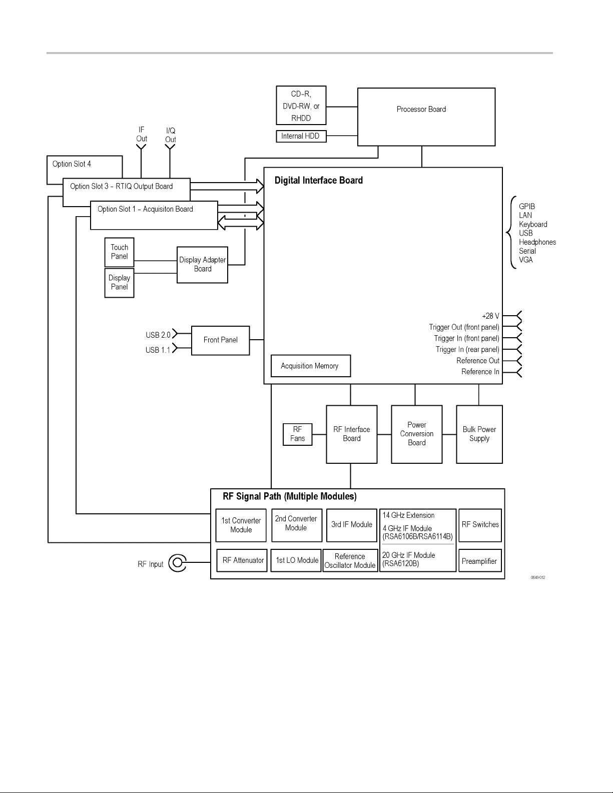
(RTSA) operation. A block diagram of the instrument is shown in this section.
(See Figure 2
General
A processor system controls the RSA6100B instrument. The instrument features
an XGA resolution flat-panel display, a transparent touch-screen, and a front-panel
with direct access to commonly used RTSA features. You can also use the RTSA
with a mouse or other pointing device, and/or a keyboard.
The RTSA uses the Microsoft Windows 7 operating system.
Signal Path and Processing
-1 on page 2-4.)
RF Signal Path
Acquisition System
Processor System
An RF signal enters the RTSA through a direct coaxial connection (N-type for the
RSA6106B and RSA6114B, 3.5 mm for the RSA6120B) to the input connector.
The RF signal path conditions the input signals and passes them to the acquisition
system for sampling and processing. The RF signal path consists of three
frequency conversion stages, band-limiting filters, and signal level adjustment
stages. The purpose of t
portion of the input signal range to a intermediate frequency (IF) where it can be
sampled by a high dynamic range A/D.
Control of the RF signal path is performed by the processor system.
The acquisition system samples the IF signal and converts it to digital signals.
These digital signals are then filtered numerically and processed either for direct
display or by measurement applications to provide metrics of signal quality
to the user. The acquisition d ata processing is performed by one of several
field-programmable gate arrays (FPGAs) under control of the processor. The
processor performs measurement applications.
The processor system consists of a COM Express PCI-based processor board and
a digital interface board that connects the processor to the acquisition board.
he RF signal path is to translate a band-limited replica of a
Trigger Inputs
RSA6100B Series Service Manual 2–1
There are two coaxial trigger inputs. One is on the front panel below the display
and the other is on the rear panel. Both trigger inputs connect directly to the digital
interface board. Trigger signals are processed by an FPGA on the digital interface
board. The information from the trigger system is combined with acquisition
data by the processor system.
Page 24

Theory of Operation
Display Panel
Display system
Touch Panel
Front Panel
The Trigger Out
The trigger out signal comes from the Acquisition Control FPGA via the digital
interface board.
Waveforms, spectral traces, measurement results, and control menus are displayed
on a 10.4 inch, color, active-matrix LCD display with touch panel.
The display system consists of a display adapter board, which sends text and
waveform information to the display panel.
The display adapter board sends information from the touch panel to the processor.
The touch panel appears as a USB HID device in the Window Device Manager
tool.
The processor system reads the front-panel switches and encoder. The processor
alsoturnstheLEDsonandoff.
signal is accessed below the display with a coaxial connection.
The ON/STBY switch passes through th
interface board, and to the processor on the front panel board.
Communication between the processor system and the front panel is performed
over an internal USB connection.
The DVD-RW, removable HDD (hard disk drive), or removable solid-state hard
drive communicate over a SATA connection directly to the processor system.
e display adapter board, the digital
Rear Panel
The following table describes the connectors available on the rear panel.
Table 2-1: Rear panel connectors
Name Input or Output Connector type Description
Reference In
Reference Out Output BNC 10 MHz output or loop-through of user
LAN
USB Input/Output USB Two USB 2.0 connectors
Keyboard Input
Input
Input/Output
BNC External time-base reference. See data sheet
for signal quality requirements.
Reference In signal
RJ-45
PS/2 Keyboard-only PS/2 connector
10/100/1000baseT Ethernet connector
2–2 RSA6100B Series Service Manual
Page 25

Theory of Operation
Table 2-1: Rear panel connectors (cont.)
Name Input or Output Connector type Description
VGA Output D-Sub
Serial Input/Output D-Sub Serial communications port (COM2) to
Trigger In Input
Headset
+28 V
GPIB Input/Output
IF Output Output BNC 500 MHz Analog IF Output signal (Option 05)
Digital I/Q Output
Output
Output BNC
BNC TTL Gate/trigger input signal
3.5 mm stereo E xternal headphone connection
IEEE-488
2x50
External monitor connector
processor system
Noise source drive power
General P urpose Interface Bus
Two connectors for digital I and Q output
signals. (Option 05)
All connections except the IF Output and Digital I/Q are connected directly to the
digital interface board. The IF Output and Digital I/Q outputs are connected to the
-Time I/Q (RTIQ) option board.
Real
Power Supply
Fans
Power Conversion board provides instrument power. The Power Conversion
The
board consists of several switching supplies that translate and balance the power
taken from the power supply module.
Power is distributed from the Power Conversion board to both the RF Deck and
the Digital Interface board.
The ON/STBY switch, located on the front panel, controls all of the power to the
instrument except for the part of the circuitry in the standby power supply.
Seven individual fans provide cooling to the RTSA. Three fans are d edicated to
the RF Deck and are controlled by the RF Interface. Two fans provide cooling
for the digital side of the instrument.
The bulk power supply module has an internal fan. Control signals to the power
supply fan are sent through the Power Conversion board from the Digital Interface
board.
A seventh fan is resident on the processor board heat sink, and is controlled by
theCOMExpressPCboard.
If Option 200 is installed, an additional fan helps cool the instrument.
RSA6100B Series Service Manual 2–3
Page 26
Theory of Operation
Figure 2-1: RSA6100B Series block diagram
2–4 RSA6100B Series Service Manual
Page 27

Adjustment Procedures
Page 28

Page 29

Adjustment Procedure
There are no physical user adjustment procedures for the RSA6100B Series
instruments. However, you can run Alignments from the RSA6100B Series
application.
Running Ali
Alignment Status
gnments
Alignments are adjustment procedures run by the instrument using internal
reference signals and measurements, and do not require any external equipment or
connectio
There are two settings for Alignments:
If Automatically align as needed is selected, alignments run w henever the signal
analyzer detects a sufficient change in ambient conditions to warrant an alignment.
If Run alignments only when "Align Now" button is pressed is selected, the
signal analyzer never runs an alignment unless you manually initiate an alignment
using the Align Now button.
NOTE. There are a few critical adjustments that must run occasionally even if
Auto
When the signal analyzer needs to run an alignment, it displays a message on
een. If no message is displayed, you can assume that the signal analyzer is
scr
properly aligned.
ns.
Automatically align as needed (Auto mode)
Run alignments only when the "Align Now" button is pressed
matically align as needed is not enabled.
Initiating an Alignment
RSA6100B Series Service Manual 3–1
To initiate an alignment:
1. Select Setup > Alignments.
2. Select the Align Now button.
The signal analyzer will run an alignment procedure. Status messages are
displayed while the alignment procedure is running. If the instrument fails the
alignment procedure, an error message will be displayed. If the instrument
fails an alignment, run Diagnostics (Tools > Diagnostics) to determine why the
alignment failed.
NOTE. While an alignment is running, both the IF and IQ outputs are disabled.
Page 30

Adjustment Procedure
Alignments During
Warm-Up
Alignments During Normal
Operation
Alignments Are Not
Calibrations
Alignments are
oscillator alignments) because default alignment values are used, (if Auto mode is
selected). During the specified period for warm-up, the instrument performance
is not warranted.
Once the signal analyzer reaches operating temperature, a full alignment is then
run every two hours (for up to two minutes). A lignments can run more frequently
if the operating temperature changes. If an alignment becomes necessary during
a measurement cycle (if Auto mode is selected), the measurement is aborted
and an alignment procedure is run. Once an alignment procedure is completed,
the measu
Alignments are adjustment procedures run by the instrument using internal
referen
Tektronix service center and require the use of traceable test equipment (signal
sources and measuring equipment) to verify the performance of the instrument.
ce signals and measurements. Calibrations can only be performed at a
not run during the 20 minute warm-up period (except, for the RF
rement cycle restarts.
3–2 RSA6100B Series Service Manual
Page 31

Maintenance
Page 32

Page 33

Maintenance
This section contains the information needed to do periodic and corrective
maintenance on the instrument. The following subsections are included:
Preventing ESD — General information on preventing damage by electrostatic
discharge.
Inspection and Cleaning — Information and procedures for inspecting the
instrument and cleaning its external and internal m odules.
Removal and Installation Procedures — Procedures for the removal of
defective modules and replacement of new or repaired modules. Also
included is a procedure for disassembly of the instrument for cleaning.
Troubleshooting — Information for isolating and troubleshooting failed
modules. Included are instructions for operating the instrument diagnostic
routines and troubleshooting trees. Most of the trees make use of the internal
diagnos
Repackaging Instructions — Information on returning an instrument for
servic
tic routines to speed fault isolation to a module.
e.
Preventing ESD
re servicing this product, read the Safety Summary and Introduction at the
Befo
front of the manual and the ESD information below.
CAUTION. Static discharge can damage any semiconductor component in this
instrument.
When perfo
adhere to the following precautions to avoid damaging internal m odules and their
components due to electrostatic discharge (ESD).
1. Minimize handling of static-sensitive circuit boards and components.
2. Transpo
or on a metal rail. Label any package that contains static-sensitive boards.
3. Discha
wrist strap while handling these modules. Perform service of static-sensitive
modules only at a static-free work station.
4. Do not allow anything capable of generating or holding a static charge on the
work station surface.
rming any service that requires internal access to the instrument,
rt and store static-sensitive modules in their static protected containers
rge the static voltage from your body by wearing a grounded antistatic
5. Handle circuit boards by the edges when possible.
RSA6100B Series Service Manual 4–1
Page 34

Maintenance
6. Do not slide the
7. Avoid handling circuit boards in areas that have a floor or work-surface
Inspection and Cleaning
Inspection and Cleaning describes how to inspect for dirt and damage. It also
describes how to clean the exterior and interior of the instrument. Inspection and
cleaning are done as preventive maintenance. Preventive maintenance, when done
regularly, may prevent instrument malfunction and enhance its reliability.
Preventive maintenance consists of visually inspecting and cleaning the
instrument and using general care when operating it.
How often preventive maintenance should be performed depends on the seve
of the e nvironment in which t he instrument is used. A proper time to perform
preventive maintenance is just before instrument adjustment.
General Care
The cabinet helps keep dust out of the instrument and should normally be in
place when operating the instrument.
circuit boards over any surface.
covering capable of generating a static charge.
rity
Interior Cleaning
Exterior Cleaning
Use a dry, low-velocity stream of air to c lean the interior of the chassis. Use a
soft-bristle, non-static-producing brush for cleaning around components. If you
must use a liquid for minor interior cleaning, use a 75% isopropyl alcohol solution
and rinse with deionized water.
WARNING. Before performing any procedure that follows, power down the
instrument and disconnect it from line voltage. Failure to do so could cause
personal injury, or death.
Clean the exterior surfaces of the chassis with a dr y lint-free cloth or a soft-bristle
brush. If any dirt remains, use a cloth or swab dipped in a 75% isopropyl alcohol
solution. Use a swab to clean narrow spaces around controls and connectors.
Do not use abrasive compounds on any part of the chassis that may damage the
chassis.
Clean the On/Standby switch using a dampened cleaning towel. Do not spray or
wet the switch directly.
CAUTION. Avoid the use of chemical cleaning agents which might damage the
plastics used in this instrument. Use only deionized water when cleaning the
menu buttons or front-panel buttons. Use a 75% isopropyl alcohol solution as a
cleaner and rinse with deionized water. Before using any other type of cleaner,
consult your Tektronix Service Center or representative.
4–2 RSA6100B Series Service Manual
Page 35

Maintenance
Inspection — Ex
terior. Inspect the outside of the instrument for damage, wear,
and missing parts, using the following table as a guide. Immediately repair defects
that could cause personal injury or lead to further damage to the instrument.
Table 4-1: External inspection checklist
Item Inspect for Repair action
Cabinet, front panel, and
cover
Front-panel knob Missing, damaged, or loose
Connectors
Carrying handle, and
cabinet feet
Accessories
Cracks, scratches,
deformations, damaged
hardware
knob
Broken shells, cracked
insulation, and deformed
contacts; dirt in connectors
Correct operation Repair o r replace defective
Missing items or parts of
items, bent pins, broken or
frayed cables, and damaged
connectors
Repair or replace defective
module
Repair or replace missing or
defective knob
Repair or replace defective
modules; clear or wash out
dirt
module
Repair or replace damaged
or missing items, frayed
cables, and defective
modules
anel Display Cleaning
Flat P
The display is a soft plastic display and must be treated with care during cleaning.
CAUTION. Improper cleaning agents or methods can damage the flat panel
display. Avoid using abrasive cleaners or commercial glass cleaners to clean the
display surface. Avoid spraying liquids directly on the display surface. Avoid
scrubbing the display with excessive force.
Clean the flat panel display surface by gently rubbing the display with a
clean-room wipe (such as Wypall Medium Duty Wipes, #05701, available from
Kimberly-Clark Corporation).
If the display is very dirty, moisten the wipe with distilled water or a 75%
isopropyl alcohol solution and gently rub the display surface. Avoid using excess
orce or you may damage the plastic display surface.
f
CAUTION. To prevent moisture from getting inside the instrument during external
cleaning, use only enough liquid to dampen the cloth or applicator.
Inspection — Interior. To access the inside of the instrument for inspection and
cleaning, refer to the Removal and Installation Procedures in this section.
RSA6100B Series Service Manual 4–3
Page 36

Maintenance
Inspect the ins
ide of the instrument for damage and wear, using the following
table as a guide. Defects found should be repaired immediately.
CAUTION. To prevent damage from electrical arcing, ensure that circuit boards
and components are dry before applying power to the instrument.
Table 4-2: Internal inspection check list
Item Inspect for Repair action
Circuit boards
Resistors Burned, cracked, broken,
Solder connections Cold solder or rosin joints.
Capacitors
Wiring and cables Loose plugs or connectors.
Chassis Dents, deformations, and
Loose, broken, or corroded
solder connections.
Burned cir
Burned, broken, or cracked
circuit-run plating.
blistered condition.
Damaged or leaking cases.
Corroded solder on leads or
termina
Burned
wiring.
damag
cuit boards.
ls.
, broken, or frayed
ed hardware.
Remove and replace
damaged circuit board.
Remove and replace
damaged circuit board.
Resolder joint and clean
with isopropyl alcohol.
Remove and replace
damaged circuit board.
Firmly seat connectors.
or replace modules
Repair
with defective wires or
cables.
Straighten, repair, or replace
tive hardware.
defec
Cleaning Procedure — Interior. To clean the instrument interior, do the following
steps:
1. Blow off dust with dry, low-pressure, deionized air (approximately 9 psi).
2. Remove any remaining dust with a lint-free cloth dampened in isopropyl
alcohol (75% solution), and a clean lint-free cloth dampened in warm
deionized water. (A cotton-tipped applicator is useful for cleaning in narrow
aces and on circuit boards.)
sp
Lubrication. There is no lubrication required for this instrument.
4–4 RSA6100B Series Service Manual
Page 37

Removal and Installation Procedures
This subsection contains procedures for the removal and installation of all
customer-replaceable mechanical and electrical modules.
Preparation
WAR NI NG . Before doing this or any other procedure in this manual, read the
Safety Summary found at the beginning of this manual. Also, to prevent possible
injury to service personnel or damage to the instrument components, read
Installation in the RSA6100B Series Real-Time S ignal Analyzers Quick Start User
Manual, a
ESD in this section.
This subsection contains the following items:
vailable on the Web at www.tektronix.com/manuals, and Preventing
Preparatory information that you need to properly do the procedures that
follow.
Removal and Installation Procedures
A list of tools required to remove and disassemble all modules.
Procedures for removal and reinstallation of the electrical and mechanical
modules.
WAR NI NG . Before doing any procedure in this subsection, disconnect the power
cord from the line voltage source. Failure to do so could cause serious injury
or death.
NOTE. Read the Equipment Required section for a list of the tools needed to
remove and install modules in this instrument. (See Table 4-3 on page 4 -6.) Read
the cleaning procedure before disassembling the instrument for cleaning.
Equipment Required. Most modules in the instrument can be removed with a
screwdriver handle mounted with a size T15, TORX screwdriver tip. Other tools
needed for complete disassembly are listed in the following table.
RSA6100B Series Service Manual 4–5
Page 38

Removal and Installation Procedures
Table 4-3: Tool
Item no. Name Description
1
2
3
4
5
6
7
8 Angle-
9
10
11
s required for module removal
Screwdriver h
T10 TORX tip Used for remo
T15 TORX tip Used for removing most instrument
T20 TORX tip Used for removing side handle
T25 TORX t
1/8 inch flat-bladed screwdriver Screwdriver for unlocking cable
#0 Phil
3/16 inch open-end wrench
5/16 inch open-end wrench
MA-800G Soldering Aid Used to remove the front panel trim
andle
ip
lips screwdriver
tip Tweezers
Accepts TORX-
TORX-driverbitforT10sizescrew
heads
screws. TOR
screw heads
screws. TORX-driver bit for T20 size
screw head
Used for r
TORX-driverbitforT25sizescrew
heads
connect
Screwd
phillips screws, CDRW, and hard drive
Used to remove front panel knobs
Used t
Used t
emoving side cover screws.
ors
river for removing small
o remove nut posts
o remove nut posts
driver bits
ving instrument. screws
X-driver bit for T15 size
s
4–6 RSA6100B Series Service Manual
Page 39

Removal and Installation Procedures
Trim, Cabinet
, and Module Removal
Use the following two tables to determine items of the instrument that you will
need to remove to access replaceable parts. The first table lists items that may
need to be rem
oved before you can acces s a replaceable module. The second
table lists customer replaceable modules and which items must be removed
to access the replaceable module. The approximate location of the primary
customer replaceable modules is shown in the following figure. (See Figure 4-1
on page 4-8.)
Table 4-4: Legend for Accessing Modules table
A - Front Cover (if installed) F- Internal Cover, bottom
B - Front panel trim
C- Cabinet, top H- Removable HDD/Solid State D rive (if
D- Cabinet, bottom I- DVD Drive/Removable HDD Frame N- Power Supply
E- Internal Cover, top
4-5: Accessing Modules
Table
les to replace
Modu
Display Assembly
Front Panel
DVD D rive (if installed)
Removable HDD Drive (if installed)
Removable Solid State Drive (if
installed)
DVD Drive/ Removable HDD Frame
gital Fan Tray (Upper Deck)
Di
RF Deck Fan Tray
Real Time IQ/IF Output Acquisition
board ( if installed)
RTT/DPSA board
PC
nternal HDD (if installed)
I
Power Conversion board
Power Supply
RF Interface board
G- DVD Drive (if installed) L- Internal HDD (if installed)
installed)
J- Display Assembly
e t hese items to access the module
Remov
ABCDEFGHI J KL MN
K- Front Panel
M- Power Conversion board
RSA6100B Series Service Manual 4–7
Page 40

Removal and Installation Procedures
Figure 4-1: Primary customer replaceable module locations
4–8 RSA6100B Series Service Manual
Page 41

Removal Procedures
Removal and Installation Procedures
NOTE. Unless directed otherwise, installation is the reverse of the removal
procedure.
These procedures assume you have access to the module you are removing. Use
the tables to determine which trim and/or modules to remove to gain access. (See
Table 4-4 on
a quick reference for customer replaceable module locations. (See Figure 4-1
on page 4-8.)
CAUTION. When removing or installing the keypad, make sure you do not touch
the switch c ontacts with your fingers. The oils in your fingers will degrade or
damage the switch contacts. To help prevent damage to the keypad use cotton
gloves w
CAUTION. To avoid damage to the front panel Standby/On switch assembly, do
not set
over the edge of the work surface could break off the On/Standby switch assembly.
page 4-7.)(See Table 4-5 on page 4-7.) A figure is also provided as
hen removing or installing the keyboard pad.
the Display module assembly on a work surface. Sliding the instrument
Display
Front Panel
orm these steps to remove the Display module:
Perf
1. Remove the four screws securing the display to the Main chassis; two on the
and two on the left side.
top
2. Disconnect the cables from the COM Express PC board and keep the cables
connected to the display assembly
3. Gently remove the Display module from the Main chassis.
CAUTION. Be careful when removing and reinstalling the Display module cables.
f the connectors have bent pins or are installed incorrectly the Display may
I
be destroyed.
4. Disconnect the smaller Display cable from the Display Adapter board.
5. Disconnect the larger Display cable from the Display Adapter board.
Perform these steps to remove the Front Panel:
RSA6100B Series Service Manual 4–9
Page 42

Removal and Installation Procedures
Digital Deck Fans
1. Remove the six T
the top, t wo on the right side, and two o n the front.
2. Pull the Front
3. Disconnect the Front Panel cable from connector J1 on the Front Panel circuit
board.
Perform these steps to remove the fan assembly from the digital deck:
1. Unplug the fan control cable from the Main board connector, marked Fan1
and Fan2.
2. Remove th
left side of the instrument.
3. Lift the
the card cage.
NOTE. You may have a DVD drive, solid-state drive, or a removable HDD
mounted above the front panel. If you ordered a solid-state drive or a removable
HDD, the instrument will not have an internal hard disk drive.
e four T15 TORX screws securing the fan assembly, located on the
fan assembly up through the narrow slot between the side panel and
15 screws that secure the Front Panel to the c ha ssis; two on
Panel assembly from the chassis.
DVD Drive
Removable Hard Disk
Drive / Solid State Drive
PC board
Follow these steps to remove the DVD drive (if installed):
1. Detach the DVD power and data cables from the COM Express PC board.
2. Carefully cut the zip tie from the DVD cables and pull the cables through
the chassis hole.
3. Remove the two screws from the front panel of the DVD.
4. Pull the DVD drive out from the Main chassis, being careful to feed the
cables as you pull.
5. Remove the four screws securing the DVD drive to the DVD drive bracket.
Perform these steps to re move the removable hard disk drive (if installed):
1. Loosen the thumbscrews securing the drive to the front panel.
2. Grasp the drive assembly by the thumb screws and pull the assembly straight
out of the instrument.
3. Remove the four screws securing the hard drive to the bottom bracket.
Perform these steps to remove the COM Express PC board:
4–10 RSA6100B Series Service Manual
Page 43

Removal and Installation Procedures
Internal Ha
rd Disk Drive
1. Disconnect all
cables attached to the COM Express PC board.
2. Lift the latch levers on the top edge of the COM Express PC board assembly
to disconnect
it from the Digital Interface board.
3. Lift the COM Express PC board from the Signal Analyzer.
Follow these steps to remove the internal hard disk drive:
NOTE. If you have a removable HDD mounted above the front panel you will
not have an internal hard disk d rive.
1. Disconnect the power/data cable from the hard disk drive.
2. Disconn
ect the video cables from the COM Express PC board.
3. Remove the four T15 screws securing the hard disk drive assembly to the
Power S
upply shield.
4. Lift the hard disk drive up and remove it from the Signal Analyzer.
5. Remove the four screws securing the hard drive to the bracket.
Power Conversion board
Perform these steps to remove the Power Conversion board:
NOTE. Remove the Power Supply support bracket and the Power Supply before
removing the Power Conversion board.
1. Remove the cables connected to the Power Conversion board:
Table 4-6: Power conversion board connectors
nnector
Co
Number Name Number Name
J3
J4
J5
ATX PO WE R
ANALOG POWER
RF PWR CTRL
nnector
Co
J6
J7 Line trigger sense
CD-ROM/HDD
2. Remove the four T15 screws securing the Power Converter board to the
chassis.
3. Slide the Power Converter board to the right, to disengage the connector
to the Power Supply.
4. Lift the Power Converter board from the signal analyzer.
RSA6100B Series Service Manual 4–11
Page 44

Removal and Installation Procedures
Power Supply
NOTE. Remove an
bracket before removing the power supply.
Follow these steps to
1. Remove the DVD drive or removable HDD (if installed).
2. Remove the internal hard disk drive assembly (if installed).
3. Remove the six T15 screws securing the power supply access cover from
the end of the Power Supply.
4. Remove the two T15 screws securing the right side of the power supply
support bracket.
5. Remove the power supply support bracket.
6. Disconnect the line trigger cable from J7 of the Power Conversion board.
7. Disconnect the power supply cable from the line filter cable.
8. Remove the two T
top front chassis.
9. Pull the power
take a little effort to pull, as the power supply must disconnect from the power
convertor board.
y installed HDD/DVD drives from the Power Supply support
remove the power supply assembly:
15 screws securing the power supply shield tabs to the
supply assembly from the left side of the chassis. This will
CAUTION. To prevent damage to the power convertor board connector, do not lift
the left end of the power supply while pulling.
4–12 RSA6100B Series Service Manual
Page 45

Troubleshooting
Troubleshooting
WAR NI NG . Before doing this or any other procedure in this manual, read the
Safety Summa
injury to service personnel or damage to the instrument components, read
Installation in the RSA6100B Series Real-Time S ignal Analyzers Quick Start User
Manual, available on the Web at www.tektronix.com/manuals, and Preventing
ESD in this section.
ry found at the beginning of this manual. Also, to prevent possible
Troublesh
faults to a module.
This subs
on the Real-Time Signal Analyzer, including PC troubleshooting a nd Windows
operating system skills. Details of PC and Windows operation and service are
not in this manual.
For assistance, please contact your local Tektronix Service Center.
ooting contains information and procedures designed to help you isolate
ection assumes that service personnel have the skills required to work
RSA6100B Series Service Manual 4–13
Page 46

Troubleshooting
Service Level
This section contains information and procedures designed to help you isolate
faulty modules in the instrument. If a module needs to be replaced, follow the
Removal and I
Check for Common Problems
nstallation Procedures, located in this section.
Use the fol
lowing table to quickly isolate possible failures. The table lists
problems and possible causes. The list is not exhaustive, but it may help you
eliminate a problem that is quick to fix, such as a blown fuse or loose cable.
Table 4-7: Failure symptoms and possible causes
Symptom Possible cause(s)
Instrument will not power on Power cord not plugged in
Faulty power supply (check Status LEDs)
Faulty power conditioner board
Faulty front panel power switch
Faulty display adapter board
Front panel light comes on (instrument
powers on), but one or more fans will
not operate
No beeps on startup or multiple beeps
on startup (single beep is OK)
Faulty fan cable
Defective fan assembly
Faulty power supply (check Status LEDs)
Faulty Slot PC
Faulty CPU
Digital Interface board problem
Faulty Slot PC
4–14 RSA6100B Series Service Manual
Page 47

Table 4-7: Failure symptoms and possible causes (cont.)
Symptom Possible cause(s)
Flat panel display blank
BIOS setting not Advanced Chipset Features
> - On Chip VGA > Enabled - Boot Display >
CRT + LFP
Defective cable from Slot PC board to Digital
Interface board
Defective cable from display adapter board to
digital interface board
Defective cable from inverter board to display
adapter board
Defective cable from inverter board to
backlighting d isplay lamp
Defective backlighting display lamp
Faulty display
Faulty digital interface board
Troubleshooting
Faulty inverter board
Faulty display adapter board
DVD-ROM related symptoms Defective DVD -ROM
Defective DVD-ROM drive cable
Defective DVD-ROM Adapter board
Incorrect DVD-ROM configuration in the BIOS
setup
Hard disk drive related symptoms
Defective hard disk drive
Incorrect hard disk type selected in the BIOS
setup
Replaceable hard disk drive not installed
Power supply failure
Corrupted BIOS module firmware, reinstall
firmware
Loose cable
Corrupted OS image
Status Indicator LEDs
Check that the Status Indicator LEDs on the Power Converter and Digital
Interface boards to ensure the power supplies are operating. (See Figure 4-2.)
(See Table 4-8.) (See Table 4-9.)
RSA6100B Series Service Manual 4–15
Page 48

Troubleshooting
Figure 4-2: Status indicator locations
Table 4-8: Power Converter board status indicators
LED Status Indication
DS171 STANDBY
DS172 -15 V OK
DS173 -8 V OK
DS174 +8 V OK
DS175 +15 V OK
DS176 +30 V OK
Table 4-9: Digital Interface board status indicators
LED Status Indication
DS481 CLOCK FAIL (normally off)
DS482 +5 VSB OK
DS483 +5 V OK
DS484 +3.3 V OK
DS485 +2.5 V OK
DS486 +1.8 V OK
DS487 +1.5 V OK
DS488 FPGA INIT
DS489 FPGA DONE
DS4810 STATUS 0
DS4811 STATUS 1 (normally off)
4–16 RSA6100B Series Service Manual
Page 49

Diagnostics
Troubleshooting
This section describes how to use and interpret the embedded Diagnostics
Interface for both the Power On Self Tests (POST) and the Extended Diagnostics
tests. These tests are used to determine whether there has been a module failure
in the instrument.
Power On Sel
f Tests
(POST)
The Power On Self Tests (POST) run automatically, every time the instrument is
powered up. If a failure is detected during this process the POST Result view will
be displayed to show which module(s) failed. (See Figure 4-3.)
Figure 4-3: Diagnostics Power On Self Test results view
Further information about the failure can be obtained from the Diags Failure Info
tab in the Diagnostics window. (See Figure 4-4.)
Figure 4-4: Diagnostics Failure Info tab
RSA6100B Series Service Manual 4–17
Page 50

Troubleshooting
Microsoft Windows Event
Viewer
All failure inf
access the Windows Event Viewer by clicking the Event Viewer button on the
Diagnostics Failure Info tab. The Windows Event Viewer is also available in the
Administrative Tools portion of the Windows Control Panel.
NOTE. Check the timestamp in the Event Viewer, as errors are stored on disk
and may be from earlier power cycles.
The Microsoft Windows Event Viewer maintains a permanent record of instrument
diagnostics failure information, with other messages regarding the operating
system. I
access it by clicking the Event Viewer button on the Diagnostics Failure Info tab.
ormation is logged in the Windows Event Viewer. You can
f there is not a shortcut to the Event Viewer on the desktop you can
To view the Diagnostics failure information, first click the Windows Logs icon
in the left frame (under Event Viewer (Local)). Then click the Applications
icon. The view changes to show the individual error reports, as shown in the
llowing figure.
fo
Scroll through the Event list to locate error events. Pay attention to the date
nd time stamps, as the information is a permanent record and shows failure
a
information from earlier diagnostic sessions.
Also note that the Signal Analyzer diagnostic errors are labe l ed as TekRSA in the
Source column, to differentiate them from o perating system messages.
4–18 RSA6100B Series Service Manual
Page 51

Troubleshooting
Scroll through the Event list to locate error events. Pay attention to the date
and time stamps, as the information is a permanent record and shows failure
informat
Also note that the Signal Analyzer diagnostic errors are labeled as TekRSA in the
Source co
Clicking on an error message to display error information in the General or
Details
ion from earlier diagnostic sessions.
lumn, to differentiate them from operating system messages.
tabs located below the list.
Double-click an error message to open a separate window for that error message.
The window shows the date and time the error message w as generated and the
source of the error message. The text of the error message is shown in the
Description area. The three buttons at the upper right let you navigate through the
error list (using the up and down arrows), or sends the record to the default printer.
If you scroll down in the error description, the event viewer always adds a line
that says “For more information, see Help and Support Center at” and includes a
inktoMicrosoft.com.Do not use this link, as Microsoft has no information on
l
Tektronix instrument error messages.
Click Help in the Event Viewer Menu bar to open the online help and learn more
information on using the Event Viewer.
RSA6100B Series Service Manual 4–19
Page 52

Troubleshooting
Extended Diagnostics
The Extended Di
instrument, including the POST tests. Access the Extended Diagnostics by
selecting Diagnostics in the Tools menu. (See Figure 4-5.)
Figure 4-5: Starting Extended Diagnostics
agnostics allow you to run all of the diagnostics tests in the
This opens the Embedded DiagnosticsInterface. (SeeFigure4-6.)
The Diagnostics Interface allows you to select specific tests, and control how
many times the selected tests are repeated.
Figure 4-6: Embedded Diagnostics Interface
4–20 RSA6100B Series Service Manual
Page 53

Troubleshooting
In the Repeat se
radio buttons to:
A) Repeat the t
B) Repeat the test(s) until a failure occurs,
C) Repeat the test(s) continuously even if failures o ccur, or
D) Run the test(s) only one time.
Figure 4-7: Diagnostics test iteration control
While the diagnostic tests are in process, a green dot is shown beside the test that
is currently running. If the test completes successfully the green dot is replaced by
a black check mark. If the test fails, the green dot i s replaced by a red X.
gment of the window (see the following figure), you can check the
est(s) a specified number of times,
RSA6100B Series Service Manual 4–21
Page 54

Troubleshooting
Table 4-10: Dia
Module Test Error message Recommended a
Hardware
Digital Interface Board Digital Board ID Verification Failed. Send the instrument to a Tektronix
gnostic error messages
Hardware Init
Read Programmable
rt Versions
Pa
Digital Board ID
Verification
Digital Board FPGA
Load Test
ction
Digital Inter
Digital Discovery Failed. Run digital tests in extended
The Acquisition Board was not found. Send the instrument to a Tektronix
The Contin
Board was not found.
Load Digital Interface Board Failed. Send the instrument to a Tektronix
RF Interface Board not found or
FPGA Loa
First L
failed.
Reference Oscillator not found or
FPGA Load failed.
Second Converter not found. Send the instrument to a Tektronix
The T
failed.
Dev
Error reading ID's.
Unable to communicate with PPC. Send the instrument to a Tektronix
Hardware driver is not initialized
Bad FPGA file path. Reinstall the product software (use
Done bit not returned high.
face Board Not Found.
uous Time Acquisition
d failed.
O not found or FPGA Load
hird IF not found or FPGA Load
ice Driver Failed.
The Slot PC is n
with the Digital Interface board.
Restart the instrument and, if
the problem p
instrument to Tektronix Service
Center for repair.
diagnostics.
Service Ce
Replace RT
Service Center for repair.
Replace RF Interface board.
e instrument to a Tektronix
Send th
Service Center for repair.
Send the instrument to a Tektronix
Service Center for repair.
ice Center for repair.
Serv
the instrument to a Tektronix
Send
Service Center for repair.
sible Acquisition board problem.
Pos
Restart the signal analyzer. If
problem persists, return to Tektronix
vice Center for repair.
Ser
nd the instrument to a Tektronix
Se
Service Center for repair.
Service Center for repair.
ervice Center for repair.
S
Restart the signal analyzer. If
problem persists, return to Tektronix
Service Center for repair.
Tektronix part number 020-2715-XX).
Send the instrument to a Tektronix
Service Center for repair.
ot communicating
ersists, send the
nter for repair.
T/DPSA board.
4–22 RSA6100B Series Service Manual
Page 55

Table 4-10: Diagnostic error messages (cont.)
Module Test Error message Recommended action
Digital Board Register
R/W Test
Digital Board SRAM
Test
Hardware Discovery /
PPC Load
Digital FIFO Test
Read value did not match w rite value.
Unable to communicate with Digital
Interface Board.
SRAM memory failure at "memory
address"
Digital Interface Board Not Found. Restart the instrument and, if
Digital Discovery Failed.
The Acquisition Board was not found. Send the instrument to a Tektronix
The Continuous Time Acquisition
Board was not found.
Load Acquisition Board Failed.
RF Interface Board not found or
FPGA Load failed.
First LO not found or FPGA Load
failed
Reference Oscillator not found or
FPGA Load failed.
Second Converter not found. Send the instrument to a Tektronix
The Third IF not found or FPGA Load
failed.
Device Driver Failed.
Invalid number of return words. Send the instrument to a Tektronix
Bad value in returned buffer. Send the instrument to a Tektronix
Send the instrument to a Tektronix
Service Center for repair.
Send the instrument to a Tektronix
Service Center for repair.
Send the instrument to a Tektronix
Service Center for repair.
the problem persists, send the
instrument to a Tektronix Service
Center for repair.
Restart the instrument and, if
the problem persists, send the
instrument to a Tektronix Service
Center for repair.
Service Center for repair.
Replace RTT/DPSA board.
Send the instrument to a Tektronix
Service Center for repair.
Restart the instrument and, if
the problem persists, send the
instrument to a Tektronix Service
Center for repair.
Send the instrument to a Tektronix
Service Center for repair.
Send the instrument to a Tektronix
Service Center for repair.
Service Center for repair.
Send the instrument to a Tektronix
Service Center for repair.
Restart the signal analyzer. If
problem persists, return to Tektronix
Service Center for repair.
Service Center for repair.
Service Center for repair.
Troubleshooting
RSA6100B Series Service Manual 4–23
Page 56

Troubleshooting
Table 4-10: Diagnostic error messages (cont.)
Module Test Error message Recommended action
PPC returned unknown status. Send the instrument to a Tektronix
Service Center for repair.
PPC did not return POST status. Send the instrument to a Tektronix
Service Center for repair.
PPC returned POST fail. Send the instrument to a Tektronix
Service Center for repair.
Error in returned Acquisition data.
Unexpected data in SDRAM memory.
Unexpected data in Flash memory.
Verification of this supply is done by
the operator.
No audio was heard.
Bad FPGA file path. The file was not
found in the directory.
FPGA Load Failed. Send the instrument to a Tektronix
DCM Not locked. Send the instrument to a Tektronix
Send the instrument to a Tektronix
Service Center for repair.
Reseat the DIMM Acquisition
memory module in the socket. If
the problem persists, send the
instrument to a Tektronix Service
Center for repair.
Send the instrument to a Tektronix
Service Center for repair.
If 28V is not present at the rear-panel
BNC connector, check the +28V
at the test point on the power
conversion board. If the 28V is
not present, replace the power
conversion board. If the +28V is
present on the power conversion
board, send the instrument to a
Tektronix Service Center for repair.
Verify that audio is not muted and
level is set properly using Windows
Volume control. If this does not
correct the problem, send the
instrument to a Tektronix Service
Center for repair.
Service Center for repair.
Send the instrument to a Tektronix
Service Center for repair.
Service Center for repair.
Service Center for repair.
Service Center for repair.
Narrow Band
Acquisition Test
PPC POST Results
Digital Board
Acquisition Test
Digital Board SDRAM
Test
Digital Board FLASH
Test
Digital Board 28 Volt
Supply Test
Digital Board Audio
Test
NB ID Verification ID Verification Failed. Send the instrument to a Tektronix
NB FPGA Load Test
NB Register R/W Test Read /Write test failed. Send the instrument to a Tektronix
4–24 RSA6100B Series Service Manual
Page 57

Table 4-10: Diagnostic error messages (cont.)
Module Test Error message Recommended action
Wide Band Acquisition
Test
NB ID, Load, R/W, and
DCM Lock Test
NB LVDS Test NB LVDS test failed. Send the instrument to a Tektronix
NB Free Run Trigger
Test
NB Acq Pattern Test
NB Dither Test
CW Acquisition Test ADC Over range. Signal too strong. Run signal
WB ID Verification ID Verification Failed. Send the instrument to a Tektronix
Error reading Board ID.
FPGA Load Failed. Send the instrument to a Tektronix
Bad FP GA File Path. File not found
in directory.
Diagnostic R/W Failed. Send the instrument to a Tektronix
ADC DCM Not Locked. Send the instrument to a Tektronix
Local Bus DCM Not Locked. Send the instrument to a Tektronix
Free run trigger test failed. Send the instrument to a Tektronix
Unexpected Acquisition data.
Trigger timeout occurred.
Dither amplitude test failed.
Dither frequency test failed.
Signal below -50dBm. Verify that the IF cable from
No signal found in acquired spectrum. Verify Normalization source is
Send the instrument to a Tektronix
Service Center for repair.
Service Center for repair.
If the FPGA file was not found,
reinstall the product software (use
Tektronix part number 020-2715-XX).
Service Center for repair.
Service Center for repair.
Service Center for repair.
Service Center for repair.
Service Center for repair.
Send the instrument to a Tektronix
Service Center for repair.
Send the instrument to a Tektronix
Service Center for repair.
Send the instrument to a Tektronix
Service Center for repair.
path test. If the signal path test
passes and this test fails, send the
instrument to a Tektronix Service
Center for repair.
the RF deck to the Narrowband
Acquisition board IF connector is
firmly connected. Repeat the test,
if the problem persists, send the
instrument to a Tektronix Service
Center for repair.
functional by running the Signal Path
test. If that test passes and this test
still fails, send the instrument to a
Tektronix Service Center for repair.
Service Center for repair.
Troubleshooting
RSA6100B Series Service Manual 4–25
Page 58

Troubleshooting
Table 4-10: Diagnostic error messages (cont.)
Module Test Error message Recommended action
WB FPGA Load Test
WB Register R/W Test
WB ID, Load, R/W,
and DCM Lock Test
WB LVDS Test WB LVDS test failed. Send the instrument to a Tektronix
WB Free Run Trigger
Test
WB Acq Pattern Test
WB Dither Test
WB CW Acquisition
Test
FPGA File Not Found. Reinstall the product software (use
Tektronix part number 020-2715-XX).
FPGA Load Failed. Send the instrument to a Tektronix
Service Center for repair.
DCM Not locked. Send the instrument to a Tektronix
Service Center for repair.
Read / Write test failed. Send the instrument to a Tektronix
Service Center for repair.
Returns read and write values.
Error reading board ID.
FPGA Load Failed. Send the instrument to a Tektronix
FPGA File Not Found. Reinstall the product software (use
Diagnostic R/W Failed. Send the instrument to a Tektronix
ADC DCM Not Locked. Send the instrument to a Tektronix
Local Bus DCM Not Locked. Send the instrument to a Tektronix
Free run trigger test failed. Send the instrument to a Tektronix
Unexpected Acquisition data.
Trigger timeout occurred.
Dither amplitude test failed.
Dither frequency test failed.
ADC Overrange. Signal too strong. Run signal path
Signal below -50dBm. Verify that the IF cable from
Send the instrument to a Tektronix
Service Center for repair.
Send the instrument to a Tektronix
Service Center for repair.
Service Center for repair.
Tektronix part number 020-2715-XX).
Service Center for repair.
Service Center for repair.
Service Center for repair.
Service Center for repair.
Service Center for repair.
Send the instrument to a Tektronix
Service Center for repair.
Send the instrument to a Tektronix
Service Center for repair.
Send the instrument to a Tektronix
Service Center for repair.
test, if that test passes, but this test
still fails, send the instrument to a
Tektronix Service Center for repair.
the RF deck to the Narrowband
Acquisition board IF connector is
firmly connected. Repeat the test,
if the problem persists, send the
instrument to a Tektronix Service
Center for repair.
4–26 RSA6100B Series Service Manual
Page 59

Troubleshooting
Table 4-10: Diagnostic error messages (cont.)
Module Test Error message Recommended action
No signal found in acquired spectrum. Verify Normalization source is
functional by running the Signal Path
test. If that test passes and this test
still fails, send the instrument to a
Tektronix Service Center for repair.
DPSA Board DPSA ID Verification DPSA Board ID Verification Failed. If ID was not found or a board other
than the DPSA Board was found,
Version/ID is nonfunctional. Replace
the RTT/DPSA Board.
DPSA and Power
Trigger FPGA Load
Test
DPSA Register R/W
Test
DPSA Frame Transfer
Test
Bad DPSA FPGA file path. The file
was not found in the directory.
Bad Power Trigger FPGA file path.
The file was not found in the directory.
DPSA FPGA Load Failed. Replace the RTT/DPSA board.
Power Trigger FPGA Load Failed. Replace the RTT/DPSA board.
DCM Not locked. Replace the RTT/DPSA board.
Read /Write test failed. Replace the RTT/DPSA board.
Returns read and write values.
FPGA File not found. Reinstall the product software (use
FPGA Load Failed. Replace the RTT/DPSA board.
Frame data test failed when looking
for incrementing pattern.
Reinstall the product software (use
Tektronix part number 020-2715-XX).
Reinstall the product software (use
Tektronix part number 020-2715-XX).
If the problem persists, send the
instrument to a Tektronix Service
Center for repair.
If the problem persists, send the
instrument to a Tektronix Service
Center for repair.
If the problem persists, send the
instrument to a Tektronix Service
Center for repair.
If the problem persists, send the
instrument to a Tektronix Service
Center for repair.
Replace the RTT/DPSA board.
If the problem persists, send the
instrument to a Tektronix Service
Center for repair.
Tektronix part number 020-2715-XX).
If the problem persists, send the
instrument to a Tektronix Service
Center for repair.
Replace the RTT/DPSA board.
If the problem persists, send the
instrument to a Tektronix Service
Center for repair.
RSA6100B Series Service Manual 4–27
Page 60

Troubleshooting
Table 4-10: Diagnostic error messages (cont.)
Module Test Error message Recommended action
DPSA LVDS Test The DPSA LVDS test failed. Replace the RTT/DPSA board.
If the problem persists, send the
instrument to a Tektronix Service
Center for repair.
FM/AM Audio Test
First LO Module First LO ID Test Board not found. Run the PPC load test. This will
First LO FPGA Load
Test
First LO Register R/W
Test
First LO ADC test Offset loop error exceeds positive
No audio was heard.
FPGA Load failed. Send the instrument to a Tektronix
Read /Write test failed. Send the instrument to a Tektronix
threshold.
Offset loop error exceeds negative
threshold.
Yig loop is unlocked.
Coarse loop is unlocked. Send the instrument to a Tektronix
Fine loop is unlocked.
15V supply voltage is over/under
voltage.
8V supply voltage is over/under
voltage.
20V supply voltage is over/under
voltage.
Replace the RTT/DPSA board.
If the problem persists, send the
instrument to a Tektronix Service
Center for repair.
rerun hardware discovery. If error
persists, send the instrument to a
Tektronix Service Center for repair.
Service Center for repair.
Service Center for repair.
Warning only.
Warning only.
Send the instrument to a Tektronix
Service Center for repair.
Service Center for repair.
Send the instrument to a Tektronix
Service Center for repair.
Run the RF Interface ADC test
to verify a power supply problem.
Check the Digital Interface board
power supply status LEDs. (See
Table 4-9.)
Run the RF Interface ADC test
to verify a power supply problem.
Check the Digital Interface board
power supply status LEDs. (See
Table 4-9.)
Run the RF Interface ADC test
to verify a power supply problem.
Check the Digital Interface board
power supply status LEDs. (See
Table 4-9.)
4–28 RSA6100B Series Service Manual
Page 61

Troubleshooting
Table 4-10: Diagnostic error messages (cont.)
Module Test Error message Recommended action
First Converter Module First LO ID Test Board not found. Run the PPC load test. This will
rerun hardware discovery. If error
persists, send the instrument to a
Tektronix Service Center for repair.
First LO FPGA Load
Test
First Converter ADC
test
FPGA Load failed. Send the instrument to a Tektronix
Service Center for repair.
FLK027 IF Ampl Drain over/under
Current.
FLK107 IF Amp Drain over/under
Current.
HMC464 LO Amp Drain over/under
Current.
UA5M20MC LO Amplifier Drain
over/under Current.
UA5M20MC Doubler Amplifier Drain
over/under Current.
5V Supply Over/Under Voltage. Run the RF Interface ADC test
8V Supply Over/Under Voltage. Run the RF Interface ADC test
10V Supply Over/Under Voltage. Run the RF Interface ADC test
11.5V Supply Over/Under Voltage. Run the RF Interface ADC test
3V Supply Over/Under Voltage. Run the RF Interface ADC test
Send the instrument to a Tektronix
Service Center for repair.
Send the instrument to a Tektronix
Service Center for repair.
Send the instrument to a Tektronix
Service Center for repair.
Send the instrument to a Tektronix
Service Center for repair.
Send the instrument to a Tektronix
Service Center for repair.
to verify a power supply problem.
Check the Digital Interface board
power supply status LEDs. (See
Table 4-9.)
to verify a power supply problem.
Check the Power Conversion board
power supply status LEDs. (See
Table 4-9.)
to verify a power supply problem.
Check the Power Conversion board
power supply status LEDs. (See
Table 4-9.)
to verify a power supply problem.
Check the Power Conversion board
power supply status LEDs; see table
4-9.
to verify a power supply problem.
Check the Digital Interface board
power supply status LEDs. (See
Table 4-9.)
RSA6100B Series Service Manual 4–29
Page 62

Troubleshooting
Table 4-10: Diagnostic error messages (cont.)
Module Test Error message Recommended action
-5V Supply Over/Under Voltage. Run the RF Interface ADC test
to verify a power supply problem.
Check the Power Conversion board
power supply status LEDs. (See
Table 4-9.)
Second Converter
Module
Third IF Module
Second Converter ID
Test
Second Converter
ADC Test
Third Converter ID
Test
Third IF FPGA Load
Test
Third IF Register R/W
Test
Third IF ADC Test 3rd IF Offset Fine Step Pll not locked. Send the instrument to a Tektronix
Board not found. Run the PPC load test. This will
rerun hardware discovery. If error
persists, send the instrument to a
Tektronix Service Center for repair.
LO2 Amplitude LOW Send the instrument to a Tektronix
Service Center for repair.
No LO2 PLL Beatnote. Send the instrument to a Tektronix
Service Center for repair.
LO2 not Phase Locked. Send the instrument to a Tektronix
Service Center for repair.
LO2 Frequency control DAC is set
too High.
LO2 Frequency control DAC is set
too Low.
Board not found. Run the PPC load test. This will
FPGA Load failed. Send the instrument to a Tektronix
Read /Write test failed. Send the instrument to a Tektronix
Returns read and write values.
3rd IF Offset Pll not locked. Send the instrument to a Tektronix
3rd IF Output Pll not locked. Send the instrument to a Tektronix
3rd IF Output Pll Tune voltage out of
range.
The +5V supply to the 3rd IF board
is under voltage.
Send the instrument to a Tektronix
Service Center for repair.
Send the instrument to a Tektronix
Service Center for repair.
rerun hardware discovery. If error
persists, send the instrument to a
Tektronix Service Center for repair.
Service Center for repair.
Service Center for repair.
Send the instrument to a Tektronix
Service Center for repair.
Service Center for repair.
Service Center for repair.
Service Center for repair.
Run the RF Interface ADC test to
verify a power supply problem.
Run the RF Interface ADC test
to verify a power supply problem.
Check the Digital Interface board
power supply status LEDs. (See
Table 4-9.)
4–30 RSA6100B Series Service Manual
Page 63

Table 4-10: Diagnostic error messages (cont.)
Module Test Error message Recommended action
Reference Oscillator
Module
Reference Oscillator
ID Test
Reference Oscillator
FPGA Load Test
Reference Oscillator
Register R/W Test
Reference Oscillator
ADC test
The -12V supply to the 3rd IF board
is over voltage.
The 12V supply to the 3rd IF board is
over voltage.
The 25V supply to the 3rd IF board is
over voltage.
The +5VA supply to the 3rd IF board
is under voltage.
The +5VA supply to the 3rd IF board
over current.
The +5VB supply to the 3rd IF board
over current.
The +5VC supply to the 3rd IF board
over current.
Board not found. Run the PPC load test. This will
FPGA Load failed. Send the instrument to a Tektronix
Read /Write test failed. Send the instrument to a Tektronix
VXCO is not locked. Send the instrument to a Tektronix
External Ref PLL is unlocked. Information only.
REF_OSC_CW_ALC_DAC is
under/over voltage.
100 MHz Tune Voltage is under/over
voltage.
10 MHz Tune Voltage is under/over
voltage.
Oven is under/over current. Send the instrument to a Tektronix
Run the RF Interface ADC test to
verify a power supply problem.
Run the RF Interface ADC test
to verify a power supply problem.
Check the Digital Interface board
power supply status LEDs. (See
Table 4-9.)
Run the RF Interface ADC test
to verify a power supply problem.
Check the Power Conversion board
power supply status LEDs. (See
Table 4-9.)
Run the RF Interface ADC test
to verify a power supply problem.
Check the Digital Interface board
power supply status LEDs. (See
Table 4-9.)
Send the instrument to a Tektronix
Service Center for repair.
Send the instrument to a Tektronix
Service Center for repair.
Send the instrument to a Tektronix
Service Center for repair.
rerun hardware discovery. If error
persists, send the instrument to a
Tektronix Service Center for repair.
Service Center for repair.
Service Center for repair.
Service Center for repair.
Send the instrument to a Tektronix
Service Center for repair.
Send the instrument to a Tektronix
Service Center for repair.
Send the instrument to a Tektronix
Service Center for repair.
Service Center for repair.
Troubleshooting
RSA6100B Series Service Manual 4–31
Page 64

Troubleshooting
Table 4-10: Diagnostic error messages (cont.)
Module Test Error message Recommended action
RF Interface Board RF Interface ID Test Board not found. Run the PPC load test. This will
rerun hardware discovery. If error
persists, replace the RF Interface
board.
RF Interface FPGA
Load Test
RF Interface ADC test
FPGA Load failed. Replace RF Interface board.
The 15 Volt supply is over voltage.
The 15 Volt supply is under voltage.
The 8 Volt supply is over voltage.
The 8 Volt supply is under voltage.
The 12 Volt supply is over voltage.
Replace the Power Conversion
board. If the problem persists,
replace the RF Interface board. If the
problem persists, replace the power
supply. If the problem persists, send
the instrument to a Tektronix Service
Center for repair.
Replace the Power Conversion
board. If the problem persists,
replace the RF Interface board. If the
problem persists, replace the power
supply. If the problem persists, send
the instrument to a Tektronix Service
Center for repair.
Replace the Power Conversion
board. If the problem persists,
replace the RF Interface board. If the
problem persists, replace the power
supply. If the problem persists, send
the instrument to a Tektronix Service
Center for repair.
Replace the Power Conversion
board. If the problem persists,
replace the RF Interface board. If the
problem persists, replace the power
supply. If the problem persists, send
the instrument to a Tektronix Service
Center for repair.
Replace the Power Conversion
board. If the problem persists,
replace the RF Interface board. If the
problem persists, replace the power
supply. If the problem persists, send
the instrument to a Tektronix Service
Center for repair.
4–32 RSA6100B Series Service Manual
Page 65

Table 4-10: Diagnostic error messages (cont.)
Module Test Error message Recommended action
The 12 Volt supply is under voltage.
The 30 Volt supply is over voltage.
The 30 Volt supply is under voltage.
The -8 Volt supply is under voltage.
The -8 Volt supply is under voltage.
The -15 Volt supply is over voltage.
Replace the Power Conversion
board. If the problem persists,
replace the RF Interface board. If the
problem persists, replace the power
supply. If the problem persists, send
the instrument to a Tektronix Service
Center for repair.
Replace the Power Conversion
board. If the problem persists,
replace the RF Interface board. If the
problem persists, replace the power
supply. If the problem persists, send
the instrument to a Tektronix Service
Center for repair.
Replace the Power Conversion
board. If the problem persists,
replace the RF Interface board. If the
problem persists, replace the power
supply. If the problem persists, send
the instrument to a Tektronix Service
Center for repair.
Replace the Power Conversion
board. If the problem persists,
replace the RF Interface board. If the
problem persists, replace the power
supply. If the problem persists, send
the instrument to a Tektronix Service
Center for repair.
Replace the Power Conversion
board. If the problem persists,
replace the RF Interface board. If the
problem persists, replace the power
supply. If the problem persists, send
the instrument to a Tektronix Service
Center for repair.
Replace the Power Conversion
board. If the problem persists,
replace the RF Interface board. If the
problem persists, replace the power
supply. If the problem persists, send
the instrument to a Tektronix Service
Center for repair.
Troubleshooting
RSA6100B Series Service Manual 4–33
Page 66

Troubleshooting
Table 4-10: Diagnostic error messages (cont.)
Module Test Error message Recommended action
20 GHz Module
The -15 Volt supply is under voltage.
The -5 Volt supply is over voltage.
The -5 Volt supply is under voltage.
The 2.5 Volt supply is over voltage.
The 2.5 Volt supply is under voltage.
LNA current is too high
Upper limit = .095A
Current read = .xxA
LNA current is too low
Lower limit = .055A
Current read = .xxxA
ID Test Board N ot Found
FPGA Load FPGA Load Failed Send the instrument to a Tektronix
Replace the Power Conversion
board. If the problem persists,
replace the RF Interface board. If the
problem persists, replace the power
supply. If the problem persists, send
the instrument to a Tektronix Service
Center for repair.
Replace the Power Conversion
board. If the problem persists,
replace the RF Interface board. If the
problem persists, replace the power
supply. If the problem persists, send
the instrument to a Tektronix Service
Center for repair.
Replace the Power Conversion
board. If the problem persists,
replace the RF Interface board. If the
problem persists, replace the power
supply. If the problem persists, send
the instrument to a Tektronix Service
Center for repair.
Replace the Power Conversion
board. If the problem persists,
replace the RF Interface board. If the
problem persists, replace the power
supply. If the problem persists, send
the instrument to a Tektronix Service
Center for repair.
Replace the Power Conversion
board. If the problem persists,
replace the RF Interface board. If the
problem persists, replace the power
supply. If the problem persists, send
the instrument to a Tektronix Service
Center for repair.
Send the instrument to a Tektronix
Service Center for repair.
Send the instrument to a Tektronix
Service Center for repair.
Send the instrument to a Tektronix
Service Center for repair.
Service Center for repair.
4–34 RSA6100B Series Service Manual
Page 67

Troubleshooting
Table 4-10: Diagnostic error messages (cont.)
Module Test Error message Recommended action
Read/Write Test Read/Write Test Failed Send the instrument to a Tektronix
Service Center for repair.
Diag ADC Test 5VA Supply Over Voltage Send the instrument to a Tektronix
Service Center for repair.
5VA Supply Under Voltage Send the instrument to a Tektronix
Service Center for repair.
5VC Supply Over Voltage Send the instrument to a Tektronix
Service Center for repair.
5VC Supply Under Voltage Send the instrument to a Tektronix
Service Center for repair.
5VPin Supply Over Voltage Send the instrument to a Tektronix
Service Center for repair.
5VPin Supply Under Voltage Send the instrument to a Tektronix
Service Center for repair.
–40V Supply Under Voltage Send the instrument to a Tektronix
Service Center for repair.
–40V Supply Over Voltage Send the instrument to a Tektronix
Service Center for repair.
–5VPin Supply Over Voltage Send the instrument to a Tektronix
Service Center for repair.
–5VPin Supply Under Voltage Send the instrument to a Tektronix
Service Center for repair.
Signal Path Signal Path Test The attenuator test failed. Send the instrument to a Tektronix
Service Center for repair.
The 200 MHz CW normalization
source to 3rd IF path test failed.
The PRN normalization source to 3rd
IF path test failed.
The 100 MHz CW normalization
source to 3rd IF path test failed.
The 3 GHz preamp path test failed. Send the instrument to a Tektronix
The 200 MHz CW source to NB
Acquisition Board path failed.
The 200 MHz CW source to WB
Acquisition Board path failed.
Send the instrument to a Tektronix
Service Center for repair.
Send the instrument to a Tektronix
Service Center for repair.
Send the instrument to a Tektronix
Service Center for repair.
Service Center for repair.
Send the instrument to a Tektronix
Service Center for repair.
Send the instrument to a Tektronix
Service Center for repair.
RSA6100B Series Service Manual 4–35
Page 68

Troubleshooting
Table 4-10: Diagnostic error messages (cont.)
Module Test Error message Recommended action
Front Panel
Front Panel Test
Sweep Speed Test Sweep Speed failed.
Front Panel LCD test failed. Replace the LCD display.
Front Panel Button test failed. Replace the front panel keypad.
A failure indicates that the sweep
time is too long.
Failure limits are set wide: the WB
failure limit equals 5 seconds and NB
failure limit equals 10 seconds.
Information only.
4–36 RSA6100B Series Service Manual
Page 69

Replaceable Parts
Page 70

Page 71

Replaceable Parts
This section contains a list of the replaceable modules for the instrument. Use this
list to identify and order replacement parts.
Parts Ordering Information
Replacement parts are available through your local Tektronix field office or
representative.
Changes to Tektronix products are sometimes made to accommodate improved
components as they become available and to give you the benefit of the latest
improvements. Therefore, when ordering parts, it is important to include the
followin
If you order a part that has been replaced with a different or improved part, your
local Tektronix field office or representative will contact you concerning any
change in part number.
ginformationinyourorder:
Part number
Instrument type or model number
Instrument serial number
Instrument modification n umber, if applicable
RSA6100B Series Service Manual 5–1
Page 72

Replaceable Parts
Module Servicing
Modules can be s
your local Tektronix service center or representative for repair assistance.
Module Exchange. In some cases you may exchange your module for a
remanufactured module. These modules cost significantly less than new modules
and meet the same factory specifications. For more information about t he module
exchange pr
Tektronix sales office or distributor; see the Tektronix Web site for a list of offices:
www.tektronix.com.
Module Repair and Return. You may ship your module to us for repair, after
which we will return it to you.
New M odules. You may purchase replacement modules in the same way as other
replacement parts.
erviced by selecting one of the following three options. Contact
ogram, call 1-800-833-9200. Outside North America, contact a
5–2 RSA6100B Series Service Manual
Page 73

Using the Replaceable Parts List
This section contains a list of the mechanical and/or electrical components that
are replaceable for the instrument. Use this list to identify and order replacement
parts. The following table describes each column in the parts list.
Column Column name Description
1
2 Tektronix part number
3 and 4
5
6
Figure & index number Items in this section are referenced by figure and index numbers to the exploded view
illustrations that follow.
Use this part number when ordering r eplacement parts from Tektronix.
Serial number Column three indicates the serial number at which the part w as first effective.
Column fo
indicates the part is good for all serial numbers.
Qty This indicates the quantity of parts used.
Name & description An item name is separated from the description by a colon (:). Because of space
limitations, an item name may sometimes appear as incomplete. Use the U.S.
Federal
Catalog handbook H6-1 for further item name identification.
Replaceable Parts
ur indicates the serial number at which the part was discontinued. No entry
Abbreviations
viations conform to American National Standard ANSI Y1.1-1972.
Abbre
RSA6100B Series Service Manual 5–3
Page 74

Replaceable Parts
Table 5-1: Exte
rnal parts
Tektronix
Fig. & index
number
5-1-1 200-5163-00 1
-2
-3 212-0234-00 2
-4 211-072 0-
-5
-6 200-5173-00 1
-7
-8 211-1224-00 11
-9 211-1050-00 34
-10 200-451
-11 333–4664–00 1 Replaced by item 19.
-12 211-12
-13 101-0152-00 1 Replaced by item 19.
-14 200-51
-15 407-5530-00 2
-16 367-0542-00 2
-17 211-1230-00 4
-18 212-
-19 101-0170-00 1
not shown 020-3016-00 1
part
number
367-0528-00 1
407-4887-00 1
348-1648-00 4
200-5196
0650-00
-00
9-00
24-00
49-00
00
Serial no.
effective
Serial no.
discont'd Qty Name & descript
COVER; TOP COSMETIC,ALUM; SAFETY CONTROLLED
HANDLE,CARRYING; DUAL DUROMETER MOLDED,POLYPROPYLENE,VINYL GRIP
SECTION,SAFETY CONTROLLED
**ATTACHED PARTS**
BRACKET; HAN
BLUE,SAFETY CONTROLLED
**END ATTAC
SCREW,MACHINE; 8-32X 1-1/2 PAN, TORX, ZINC PLATED STEEL, BLACK, 8C150MTPKZ
4
1
1
3
1
4
SCR, ASSEM WSHR; 6-32 X 0.500, PNH, STEEL, ZINC FINISH, T15 TORX DR, MACHINE
FOOT; REAR
COVER; BOTTOM,INTERNAL; SAFETY CONTROLLED
COVER; BOTTOM COSMETIC; SAFETY CONTROLLED
SCREW, 6–
SCREW, MACHINE; 6-32 X 0.312 L, PNH, STEEL, ZINC FINISH, T15
COVER,FRONT; PC ABS,17.420L X 8.670W X 2.000TH,TEK BLUE
SCREW, 6-32 X 0.375L, PNH, BLACK, T15, NYLOC
COVER; TOP,INTERNAL; SAFETY CONTROLLED
BRACK
HANDLE, CARRYING; 0.375 AL, POWDER COAT, PEKING GRAY FULLER OBRIEN,
SAFET
SCREW; 10-32X.500 SOC CAP,18-8 ZINC PLATED STEEL
SCREW,MACHINE; 10-32 X 0.437,FLH,100 DEG,SST PSVT,POZ
COSM
SOFTWARE;OS RESTORE DVD KIT, WINXP EMBEDDED;RSA61XXB SERIES
ion
DLE BASE,PC/ABS ALLOY,BAYER BAYBLEND FR-110,TEK
HED PARTS**
W/CORD WRAP,THERMO PLASTIC; SAFETY CONTROLLED
32 X 0.375L, PNH, BLACK, T15, NYLOC
ET,MOUNTING; CARRYING HANDLE, LANCER
Y CONTROLLED
ETIC FRONT (ACQUISITION TO TRIG AND TRIM)
5–4 RSA6100B Series Service Manual
Page 75

Replaceable Parts
Figure 5-1: External parts
RSA6100B Series Service Manual 5–5
Page 76

Replaceable Parts
Table 5-2: Disp
Fig. &
index
number
5-2-1 200-5143-00 1
-2 407-5476-00 1
-3 119-7678-00 1
-4 065-0913-00 1
-5
-6 441-2620-01 1
-7
-8 407-5337-00 1
-9 174-5349-00 1
-10 174-5650-00 1
-11 211-0950-00 4
-12 211-1050-00 16
-13 614-1050-00 1
-14 174-5080-00 1
-15 174-5101-00 1
-16 878-0417-00 1
-17 878-0411-00 1
-18 260-2719-00 1
-19 333-4618-00 1
-20 366-0849-00 1
-21 650-5304-00 1
-22 259-0155-01 1
-23 407-5504-00 1
-24 119-7537-00 1
-25 119-7550-00 1
-26 407-5548-00 1
-27 878-0414-00 1
-28 174-5087-00 1
-29 174-5086-00 1
-30 174-4791-00 1
lay, front panel, DVD, and removeable hard drive
Tektronix
part
number
407-5473-00 1
211-1050–00 6
Serial
no.
effective
Serial
no.
discont'd Qty Name & description
COVER; CD,SAFETY CONTROLLED
BRACKET,DVD-CD/RW
DISK DRIVE; OPTICAL,CD-RW/DVD-R/RW
DVD+R/RW,16.7 MB/SEC,650MEG/8.5GIG,SATA/ATAPI;TEAC MODEL DV-W28S-V93
DRIVE ASSY; REMOVABLE SOLID STATE, PROGRAMMED
BRACKET; HARD DRIVE, 2.5 IN, REMOVABLE
CHASSIS ASSY; HD-FD-FRAME,SAFETY CONTROLLED
SCREW, MACHINE; 6-32 X 0.312L, PNH, STEEL, ZINC FINISH, T15
HDD CABLE BRACKET
CABLE ASSY; SATA COMBO, HARD DRIVE CABLE W LATCH
CABLE, SATA-DVD, DATA AND POWER, SAFETY CONTROLLED
SCREW, MACHINE; M2X.4X3L, PNL, PNH, STEEL
SCREW,MACHINE; 6-32 X 0.312 L,PNH,STEEL, ZINC FINISH,T15
FRONT PANEL CONTROL ASSY,(STD);
CA ASSY,SP; IDC,RIBBON,FRT PANEL TO DIG INTF,2X10; SAFETY CONTROLLED
CA ASSY, SP, IDC, RIBBON, AUDIO COM EXPRESS DC TO DIG INTERF, 2X5
CIRCUIT BD ASSY; USB I/0
CIRCUIT BD SUBASSY; FRONT PANEL BOARD
SWITCH,KEYPAD; ELASTOMERIC,FRONT PANEL
FRONT SUBPANEL; ASSEMBLY,INCLUDES BRACKET,BEZEL, & LABEL, SAFETY
CONTROLLED
KNOB; GENERAL PURPOSE
MODULE ASSY; DISPLAY WITH LCD
FLEX CIRCUIT; POWER SWITCH,W/LED
BRACKET, DISPLAY FRONT; SAFETY CONTROLLED
TOUCH SCREEN ; TOUCH PANEL;10.4 RESISTIVE, 5-WIRE INTERFACE, W/GASKETS
DISPLAY MODULE; LCD;1024 X 768;10.4 INCHES DIAGONAL, TFT, LED
BRACKET, DISPLAY
CIRCUIT BD SUB-ASSY; INTERCONNECT DISPLAY ADAPTER
CA ASSY,SP; IDC,RIBBON,DISP ADAPT TO DIG INTERF,2MM,2X15; SAFETY
CONTROLLED
CA ASSY,SP; IDC,RIBBON,DISP ADAPT TO DIG INTERF,2MM,2X10; SAFETY
CONTROLLED
CA ASSY; DISPLAY ADAPTER TO XGA DISPLAY,SAFETY CONTROLLED
5–6 RSA6100B Series Service Manual
Page 77

Replaceable Parts
Figure 5-2: Display, front panel, DVD, and removeable hard drive
RSA6100B Series Service Manual 5–7
Page 78

Replaceable Parts
Figure 5-3: Detail 1 of display and front panel cabling
5–8 RSA6100B Series Service Manual
Page 79

Replaceable Parts
Figure 5-4: Detail 2 of display and front panel cabling
RSA6100B Series Service Manual 5–9
Page 80

Replaceable Parts
Figure 5-5: Detail 3 of display and front panel cabling
5–10 RSA6100B Series Service Manual
Page 81

Replaceable Parts
Table 5-3: Modu
Fig. &
index
number
5-6-1 650-5572-00 1
-2 407-5478-00 1
-3 211-1050-00 10
-4 039-0198-00 4
-5
-6 211-1346-00 4
-7
-8 407-5358-00 1
-9 436-0435-00 1
-10 664-5898-05 1
-11 200-4961-00 1
-12
-13 211-0450-00 4
-14 200-4962-00 1
-15 174-5106-01 2
-16 407-5181-00 1
les
Tektronix
part
number
214-5296-00 1
863-0273-00 1
Opt 05
Serial
no.
effective
Serial
no.
discont'd Qty Name & description
CIRCUIT BD ASSY; COM EXPRESS, PB-FREE
BRACKET, COM EXPRESS CARRIER; SAFETY CONTROLLED
SCREW, MACHINE; 6-32 X 0.312 L, PNH, STEEL, ZINC FINISH, T15
PROCESSOR MODULE; PCI, SOM—5787
FAN, TUBEAXIAL; 12 VDC, 0.073A, 0.876W, 6500 RPM, 6.0 CFM, 40 MM X 10 MM,
W/LEADS; SAFETY CONTROLLED
SCREW, MACHINE, PANHEAD M3 X 0.5 X 26 MM, PHILLIPS
CIRCUIT BD ASSY; RTT/DPX,PB-FREE
BRACKET,HEATSINK FAN
FAN ASSEMBLY
CIRCUIT BD ASSY; REALTIME I/Q OUTPUT, (OPT. 05 ONLY)
COVER; REAR PANEL,OPTION(BLANK); SAFETY CONTROLLED (ALL EXCEPT
OPT. 05)
1
OPTION 05; IF OUTPUT, DIGITAL IQ OUTPUT
SCREW, MACHINE; 2.5MM X 0.45 X 6MM, PNH, STEEL, ZINC PLATED, T8 TORX
DRIVE (OPT. 05 ONLY)
COVER; R EAR PANEL, OPTION (I&Q OUT, IF OUT); SAFETY CONTROLLED (OPT.
05 ONLY)
CA ASSY,SP; IDC,TW FLAT,I & Q OUTPUT TO REAR PANEL,50 POS; SAFETY
CONTROLLED, (OPT. 05 ONLY)
BRACKET, GROUNDING (LAN AND PS/2)
RSA6100B Series Service Manual 5–11
Page 82

Replaceable Parts
Figure 5-6: Modules
5–12 RSA6100B Series Service Manual
Page 83

Replaceable Parts
Figure 5-7: Detail 1 of PC cabling
RSA6100B Series Service Manual 5–13
Page 84

Replaceable Parts
Figure 5-8: Detail 2 of PC cabling
5–14 RSA6100B Series Service Manual
Page 85

Replaceable Parts
Figure 5-9: Detail of RT/IQ Option 05 cabling
RSA6100B Series Service Manual 5–15
Page 86

Replaceable Parts
Table 5-4: Powe
r supply and internal hard drive
Tektronix
Fig. & index
number
5-10-1 119-6986-06 1
-2 211-0718-00 6
-3 407-5477-00 1
-4 441-2619-00 1
-5
-6 407-5472-0
-7
-8 174-5089-00 1
-9 174-5090-
-10 174-5101-00 1
-11 174-5100-00 1
-12 664-5887-01 1
-13 211-0510-00 8
-14 200-5135-00 1
-15
-16 211-0380-00 2
part
number
211-1050-00 9
065-0914-00 1
174-52
119-7086-00 1
27-00
0
00
Serial no.
effective
Serial no.
discont'd Qty Name & descript
ion
POWER SUPPLY; AC-DC;460W;+3.3V 40A,+5V 34A,+12V 25A,-12V 1A,+5VSB
2A;90-264VAC
SCREW, MACHINE; 6-32 X 0.312, FLH100, STEEL, ZINC FINISH, T10 TORX DR
BRACKET; POWER SUPPLY; SAFETY CONTROLLED
BRACKET; HAR
SCREW, MACHINE; 6-32 X 0.312 L, PNH, STEEL, ZINC FINISH, T15
1
1
1
BRACKET; HARD DRIVE, 3.5 INCH HARD DRIVE
DRIVE ASSY
CA ASSY,PWR; DISCRETE,DIG INTERFACE,2X10,18AWG; SAFETY CONTROLLED
CA ASSY,PWR; DISCRETE,DIG INTERFACE,2X6,20AWG; SAFETY CONTROLLED
CA ASSY,S
CONTROLLED
CA ASSY,P
CONTROLLED
CIRCUIT
BOARD,TESTED,664588700,679588700,389366100,WIRED
SCREW, M
COVER, POWER SUPPLY
CABLE ASSY;LINE FILTER; SAFETY CONTROLLED
**ATTA
FILTER,EMI; AC LINE CONNECTOR/INPUT FILTER;6.0A,120-250VAC,DC-400 HZ,2.2 NF
CY,10
CONTROLLED;FN9222-6/06 (LINE FILTER)
**EN
SCREW,MACHINE; 4-40 X 0.375,FLH,STEEL, ZINC FINISH, T8
,47-440HZ
D DRIVE, 3.5 INCH HARD DRIVE
, WITH PACKAGING AND COA; FIXED INTERNAL DISK, PROGRAMMED
P; IDC,RIBBON,AUDIO SLOTPC TO DIG INTERF,2X5,2MM; SAFETY
WR; IDC,RIBBON,PWR CONV TO BULKHEAD,2X25,0.100 CTR; SAFETY
BD ASSY; POWER CONVERSION
ACHINE; 6-32 X 0.375, PNH, ZINC PLATED STEEL, T15
CHED PARTS**
0 NF CX,IEC INPUT,FAST-ON/SOLDER LUG OUTPUT,CHASSIS MOUNT,SAFETY
D ATTACHED PARTS**
5–16 RSA6100B Series Service Manual
Page 87

Replaceable Parts
re 5-10: Power supply and internal hard drive
Figu
RSA6100B Series Service Manual 5–17
Page 88

Replaceable Parts
e 5-11: Detail of power supply and internal hard drive cabling
Figur
5–18 RSA6100B Series Service Manual
Page 89

Replaceable Parts
Table 5-5: Uppe
Fig. &
index
number
5-12-1 211-1050-00 25
-2
-3 174-5212-00 1
-4 174-5201-00 1
-5
-6 407-5055-00 1
-7
-8 407-5480-00 1
-9 174-5066-00 1
-10
r and lower deck fans
Tektronix
part
number
436-0424-00 1
119-7182-00 2
407-5062-00 1
213-1061-00 2
119-7172-00 1
436-0423-00 3
119-7183-00 1
407-5052-00 1
Serial
no.
effective
Serial
no.
discont'd Qty Name & description
SCREW,MACHINE; 6-32 X 0.312 L,PNH, STEEL, ZINC FINISH, T10, TORX
ASSY,FAN TRAY; WITH FANS MOUNTED (UPPER DECK); SAFETY CONTROLLED
FAN, TUBEAXIAL; 12VDC, 0.40A, 4.80W, 2500RPM, 100.6CFM, 120MM, LEADS
W/CONN; SAFETY CONTROLLED (SUBPARTS OF 436-0424-00)
BRACKET; FAN MOUNTING,UPPER DECK; SAFETY CONTROLLED (SUBPART OF
436-0424-00)
CA ASSY,SP; IDC,RIBBON,CONTROL LINES,BULKHEAD TO RF
INTERFACE,2X7,0.100CTR SAFETY CONTROLLED
CA ASSY,SP; IDC,RIBBON,GPIB,DIG INTF TO REAR PANEL; SAFETY CONTROLLED
JACKSCREW; 6-32 EXT THD, M3.5 X 0.6-6 INT THD, 410 SS, PASSIVATE
BRACKET ASSY; SPEAKER
SPEAKER; DYNAMIC;28MM DIA,8 OHM,600-7KHZ,MYLAR CONE,MG ELECT
288BB20 WITH 28 INCH CABLE;
BRACKET; BNC ADAPTER
CA ASSY,RF,FLEX-COAX; FRONT PANEL ACQ
ASSY,FAN TRAY; WITH FANS MOUNTED(RF DECK); SAFETY CONTROLLED
FAN, TUBEAXIAL; 12VDC, 0.23A, 2.76W, 3250RPM, 39CFM, 80MM X 25MM, LEADS
W/CONN; SAFETY CONTROLLED (SUBPARTS OF 436-0423-00)
BRACKET; FAN MOUNTING,RF DECK (SUBPART OF 436-0423-00)
RSA6100B Series Service Manual 5–19
Page 90

Replaceable Parts
Figure 5-12: Upper and lower deck fans
5–20 RSA6100B Series Service Manual
Page 91

Replaceable Parts
RSA6100B Series Service Manual 5–21
Page 92

Replaceable Parts
Figure 5-13: Detail of cabling shown in Figure 5-13
Table 5-6: RF interface board and cables
Fig. &
index
number
5-14-1 878-015
-2 211-1050-00
-3 174-5097-00 1
-4 174-5119-00 1
Tektronix
part
number
5-00
Serial
no.
effective
Serial
no.
discont'd Qty Name & description
1
5
CIRCUIT BD SUBASSY; RF INTERFACE BOARD;
MACHINE; 6-32 X 0.312 L,PNH,STEEL, ZINC FINISH, T15
SCREW,
CA ASSY,SP; IDC,RIBBON,CONTROL LINES,BULKHEAD TO RF INTERFACE,2X7;
CONTROLLED
SAFETY
CA ASSY,PWR; IDC,RIBBON,BULKHEAD TO RF INTERF,2X25,0.100 CTR; SAFETY
OLLED
CONTR
5–22 RSA6100B Series Service Manual
Page 93

Replaceable Parts
Figure 5-14: RF interface board and cables
RSA6100B Series Service Manual 5–23
 Loading...