

Tektronix RSA6106A, RSA6120A Service

xx
RSA6106A/RSA6114A (S/N B020000 and Above),
and RSA6120A
ZZZ
Real-Time Spectrum Analyzer
Service Manual
*P077025001*
077-0250-01


xx
RSA6106A/RSA6114A (S/N B020000 and Above),
and RSA6120A
ZZZ
Real-Time Spectrum Analyzer
Service Manual
www.tektronix.com
077-0250-01

Copyright © Tektronix. All rights reserved. Licensed software products are owned by Tektronix or its subsidiaries
or suppliers, and are protected by national copyright laws and international treaty provisions.
Tektronix products are covered by U.S. and foreign patents, issued and pending. Information in this publication
supersedes that in all previously published material. Specifications and price change privileges reserved.
TEKTRONIX and TEK are registered trademarks of Tektronix, Inc.
Contacting Tektronix
Tektronix, Inc.
14200 SW Karl Braun Drive
P.O . B ox 5 00
Beaverto
USA
For product information, sales, service, and technical support:
n, OR 97077
In North America, call 1-800-833-9200.
Worl d wide , vi s it www.tektronix.com to find contacts in your area.

Warranty
Tektronix warrants that this product will be free from defects in materials and workmanship for a period of one (1)
year from the date of shipment. If any such product proves defective during this warranty period, Tektronix, at its
option, either will repair the defective product without charge for parts and labor, or will provide a replacement
in exchange for the defective product. Parts, modules and replacement products used by Tektronix for warranty
work may be n
the property of Tektronix.
ew or reconditioned to like new performance. All replaced parts, modules and products become
In order to o
the warranty period and make suitable arrangements for the performance of service. Customer shall be responsible
for packaging and shipping the defective product to the service center designated by Tektronix, with shipping
charges prepaid. Tektronix shall pay for the return of the product to Customer if the shipment is to a location within
the country in which the Tektronix service center is located. Customer shall be responsible for paying all shipping
charges, duties, taxes, and any other charges for products returned to any other locations.
This warranty shall not apply to any defect, failure or damage caused by improper use or improper or inadequate
maintenance and care. Tektronix shall not be obligated to furnish service under this warranty a) to repair damage
result
b) to repair damage resulting from improper use or connection to incompatible equipment; c) to repair any damage
or malfunction caused by the use of non-Tektronix supplies; or d) to service a product that has been modified or
integrated with other products when the effect of such modification or integration increases the time or difficulty
of servicing the product.
THIS WARRANTY IS GIVEN BY TEKTRONIX WITH RESPECT TO THE PRODUCT IN LIEU OF ANY
OTHER WARRANTIES, EXPRESS OR IMPLIED. TEKTRONIX AND ITS VENDORS DISCLAIM ANY
IMPLIED WARRANTIES OF MERCHANTABILITY OR FITNESS FOR A PARTICULAR PURPOSE.
TRONIX’ RESPONSIBILITY TO REPAIR OR REPLACE DEFECTIVE PRODUCTS IS THE SOLE
TEK
AND EXCLUSIVE REMEDY PROVIDED TO THE CUSTOMER FOR BREACH OF THIS WARRANTY.
TEKTRONIX AND ITS VENDORS WILL NOT BE LIABLE FOR ANY INDIRECT, SPECIAL, INCIDENTAL,
OR CONSEQUENTIAL DAMAGES IRRESPECTIVE OF WHETHER TEKTRONIX OR THE VENDOR HAS
ADVANCE NOTICE OF THE POSSIBILITY OF SUCH DAMAGES.
[W2 – 15AUG04]
btain service under this warranty, Customer must notify Tektronix of the defect before the expiration of
ing from attempts by personnel other than Tektronix representatives to install, repair or service the product;


Table of Contents
General Safety Summary .......................................................................................... v
Service Safety Summary.......................................... ................................ ............... vii
Preface .............................................................................................................. ix
Manual Content ............. ................................ ................................ .................. ix
Manual Conventions.......... ................................ ................................ ................ ix
Related User Documents...................................................................................... x
Operating Information
Operating Information ........................................................................................... 1-1
Theory of Operation
Theory of Operation....................... ................................ ................................ ....... 2-1
General..................... ................................ .................................. ................. 2-1
Signal Path and Processing ................................................................................. 2-1
Display Panel.................... ................................ .................................. ........... 2-2
Front Panel ................................ ................................ ................................ ... 2-2
Rear Panel ..................... ................................ .................................. ............. 2-2
Power Supply................................................................................................. 2-3
Fans............................................................................................................ 2-3
Adjustment Procedures
Adjustment Procedure............. ................................ .................................. ............. 3-1
Running Alignments................................ .................................. ....................... 3-1
Maintenance
Maintenance....................................................................................................... 4-1
Preventing ESD .............................................................................................. 4-1
Inspection and Cleaning.................. ................................ .................................. . 4-2
Restoring the Windows Operating System (OS)..... ................................ ......................... 4-5
Creating a Disk Backup Image............................................................................. 4-6
Restoring the Instrument Operating System ........... ................................ ................... 4-7
Formatting the Drive in Option 06/08 Instruments . . . .. . ... ... ... . ... ... ... . ... ... ... . ... ... ... .. .. . ... . 4-7
Restoring the Operating System from the Instrument Hard Disk (Options 06/07) ................... 4-9
Restoring the Hard Disk from a Backup Image ..................... ................................ ..... 4-9
Removal and Installation Procedu
Preparation......................................... .................................. ....................... 4-11
Trim, Cabinet, and Module Removal....................................... ............................. 4-13
res......................................................................... 4-11
RSA6106A/RSA6114A (S/N B020000 and Above), and RSA6120A Service Manual i

Table of Contents
Removal Proced
Troubleshooting................................................................................................. 4-20
Service Level.......................... .................................. ................................ ... 4-20
Check for Common Problems............................................................................ 4-20
Diagnostics ................................................................................................. 4-23
Replaceable Parts
Replaceable Parts...... ................................ ................................ ........................... 5-1
Parts Ordering Information ................ ................................ ................................ . 5-1
Using the Replaceable Parts List........................................................................... 5-3
ures.................. ................................ .................................. ... 4-15
ii RSA6106A/RSA6114A (S/N B020000 and Above), and RSA6120A Service Manual

List of Figures
Figure 2-1: RSA6100A Series block diagram............................ ................................ ..... 2-4
Figure 4-1: Primary customer replaceable module locations.............................................. 4-14
Figure 4-2: Status indicator locations ........................................................................ 4-22
Figure 4-3:
Figure 4-4: Diagnostics Failure Info tab ..................................................................... 4-24
Figure 4-5: Event viewer initial display ... ... . ... ... ... . ... ... ... .. .. . ... ... ... . ... ... ... .. .. . ... ... ... . ... . 4-25
Figure 4-6: Event viewer applications error view ....... ................................ ................... 4-26
Figure 4-7: Event Properties window, showing error log information ................................... 4-26
Figure 4-8: Starting Extended Diagnostics ............... ................................ ................... 4-27
Figure 4
Figure 4-10: Diagnostics test iteration control ............................. ................................ . 4-28
Figure 5-1: External parts .................................. ................................ ..................... 5-5
Figure 5-2: Display, front panel, DVD, and removeable hard drive ................... ..................... 5-7
Figure 5-3: Detail 1 of display, front panel, DVD, and removeable hard drive cabling .. ... ... . ... ... . . . 5-8
Figure 5-4: Detail 2 of display, front panel, and removable hard drive cabling ........................... 5-9
re 5-5: Detail 3 of display, front panel, DVD, and removeable hard drive cabling .. ... ... . ... ... . 5-10
Figu
Figure 5-6: Modules..... ................................ .................................. ..................... 5-12
Figure 5-7: Detail 1 of Slot PC cabling ........................... ................................ ........... 5-13
Figure 5-8: Detail 2 of Slot PC cabling ........................... ................................ ........... 5-14
Figure 5-9: Detail of RT/IQ Option 05 cabling ............................................................. 5-15
Figure 5-10: Power supply and internal hard drive......................................................... 5-17
gure 5-11: Detail 1 of power supply and internal hard drive cabling................................... 5-18
Fi
Figure 5-12: Detail 2 of power supply and internal hard drive cabling ........................... ....... 5-19
Figure 5-13: Upper and lower deck fans.......... ................................ ........................... 5-21
Figure 5-14: Detail of cabling shown in Figure 5-13....................................................... 5-22
Figure 5-15: RF interface board and cables ................................................................. 5-24
Diagnostics Power On Self Test results view.................................................. 4-24
-9: Embedded Diagnostics Interface .......................... ................................ ..... 4-28
RSA6106A/RSA6114A (S/N B020000 and Above), and RSA6120A Service Manual iii

Table of Contents
List of Tables
Table 2-1: Rear panel connectors................ .................................. ............................. 2-2
Table 4-1 : E
Table 4-2: Internal inspection check list ....................................................................... 4-4
Table 4-3: Tools required for module removal............. .................................. ............... 4-12
Table 4-4: Legend for Accessing Modules table............................................................ 4-13
Table 4-5: Accessing Modules........... ................................ ................................ ..... 4-13
Table 4-6: Power conversion board connectors ...................... ................................ ....... 4-18
Table 4-7
Table 4-8: Power Converter board status indicators........................................................ 4-23
Table 4-9: Digital Interface board status indicators......................................................... 4-23
Table 4-10: Diagnostic error messages....................................................................... 4-29
Table 5-1: External parts.... .................................. ................................ ................... 5-4
Table 5-2: Display, front panel, DVD, and removeable hard drive ......................................... 5-6
Table
Table 5-4: Power supply and internal hard drive............................................................ 5-16
Table 5-5: Upper and lower deck fans .................. ................................ ..................... 5-20
Table 5-6: RF interface board and cables.................................................................... 5-23
xternal inspection checklist....................................................................... 4-3
: Failure symptoms and possible causes ... ................................ ....................... 4-20
5-3: Modules...................................... ................................ ....................... 5-11
iv RSA6106A/RSA6114A (S/N B020000 and Above), and RSA6120A Service Manual

General Safety Summary
General Safet
To Avoid Fire or Personal
Injury
ySummary
Review the fo
this product or any products connected to it.
To avoid pot
Only qualified personnel should perform service procedures.
While using this product, you may need to access other parts of a larger system.
Read the safety sections of the other component manuals for warnings and
cautions r
Use Proper Power Cord. Use only the power cord specified for this product and
certified for the country of use.
Ground the Product. This product is grounded through the grounding conductor
of the power cord. To avoid electric shock, the grounding conductor must be
connected to earth ground. Before making connections to the input or output
terminals of the product, ensure that the product is properly grounded.
Observe All Terminal Ratings. To avo i d fire or shock hazard, observe all ratings
and markings on the product. Consult the product manual for further ratings
rmation before making connections to the product.
info
llowing safety precautions to avoid injury and prevent damage to
ential hazards, use this product only as specified.
elated to operating the system.
The inputs are not rated for connection to mains or Category II, III, or IV circuits.
Power Disconnect. The power cord disconnects the product from the power source.
Do not block the power cord; it must remain accessible to the user at all times.
Do Not Operate Without Covers. Do not operate this product with covers or panels
removed.
Do Not Operate With Suspected Failures. If you suspect that there is damage to this
product, have it inspected by qualified service personnel.
Avoid Exposed Circuitry. Do not touch exposed connections and components
when power is present.
Replace Batteries Properly. Replace batteries only with the specified type and
rating.
Use Proper Fuse. Use only the fuse type and rating specifi ed for this product.
Wear Eye Protection. Wear eye protection if exposure to high-intensity rays or
laser radiation exists.
RSA6106A/RSA6114A (S/N B020000 and Above), and RSA6120A Service Manual v
General Safety Summary
TermsinthisManual
Symbols and Terms on the
Product
Do Not Operate i
Do Not Operate in an Explosive Atmosphere.
Keep Product Surfaces Clean and Dry.
Provide Prop
details on installing the product so it has proper ventilation.
These terms may appear in this manual:
WARNING.
in injury or loss of life.
CAUTION
damage to this product or other property.
These t
. Caution statements identify conditions or practices that could result in
erms may appear on the product:
DANGER indicates an injury hazard immediately accessible as you read
the ma
n Wet/Damp Conditions.
er Ventilation. Refer to the manual’s installation instructions for
Warning statements identify conditions or practices that could result
rking.
WARNING indicates an injury hazard not immediately accessible as you
the marking.
read
CAUTION indicates a hazard to property including the product.
The following symbol(s) may appear on the product:
vi RSA6106A/RSA6114A (S/N B020000 and Above), and RSA6120A Service Manual

Service Safety Summary
Service Safet
y Summary
Only qualifie
Safety Summary and the General Safety Summary before performing any service
procedures.
Do Not Service Alone. Do not perform internal service or adjustments of this
product unless another person capable of rendering first aid and resuscitation is
present.
Disconnect Power. To avoid electric shock, switch off the instrument power, then
disconnect the power cord from the mains power.
UseCareWhenServicingWithPowerOn. Dangerousvoltagesorcurrentsmay
exist in
disconnect test leads before removing protective panels, soldering, or replacing
components.
To avoid electric shock, do not touch exposed connections.
d personnel should perform service procedures. Read this Service
this product. Disconnect power, remove battery (if applicable), and
RSA6106A/RSA6114A (S/N B020000 and Above), and RSA6120A Service Manual vii

Service Safety Summary
viii RSA6106A/RSA6114A (S/N B020000 and Above), and RSA6120A Service Manual

Preface
Manual Content
Manual Conventions
This is the service manual for the RSA6100A Series Real-time Spectrum
Analyzers.
Read this preface to learn how this manual is structured, what conventions it uses,
and where you can find other information related to servicing this product.
This manual contains only information related to se rvicing an RSA6100A Series
Real-tim
the instrument or for a list of instrument specifications, refer to the appropriate
user document as described in Related User Documents on the following page.
Be sure to read the introductions to all procedures. These introductions provide
important information needed to perform the service correctly, safely, and
efficiently.
e Spectrum Analyzer. For information related to installing and operating
Module
Plug-in Module
Replaceable Parts
Safety
This manual uses certain conventions that you should become familiar with
before attempting service.
The term module refers to a collection of items that are replaceable as a unit. A
module may contain electrical and mechanical assemblies, circuit boards, and
interconnecting cables.
The term Plug-in Module refers to the units that plug into the Main Digital
Interface board.
This manual refers to any field-replaceable assembly or mechanical part by its
name or generically as a replaceable part. In general, a replaceable part is any
circuit board or assembly that is listed in the Replaceable Parts section.
Symbols and terms related to safety appear in the General Safety Summary found
at the beginning of this manual. Be sure to read both the General Safety Summary
and Service Safety Summary before performing any service to this instrument.
RSA6106A/RSA6114A (S/N B020000 and Above), and RSA6120A Service Manual ix

Preface
Related User Documents
The following related English user documents are available if you need more
information about operating the instrument. These documents are located on the
RSA6100A Series Real-time Spect rum Analyzer User Documentation CD-ROM
or can be downloaded from the Tektronix Web site (www.tektronix.com/manuals).
RSA6100A Series Real-time Spectrum Analyzer Quick Start User Manual.
This document provides the basic information you need to install and operate
the instru
for the instrument.
ment. Included is a listing of the options and accessories available
RSA6100A
Performance Verification Technical Reference (English). Contains the
following technical information about the instrument:
Electrical and physical specifications, including a list of certifications
and compliances.
A performance verific ation procedure to check instrument performance
against guaranteed specifications.
RSA6100A Series Real-time Spectrum Analyzer Programmer Manual
(English). Describes the GPIB instrument programming commands and
interface.
RSA6100A Series Real-time Spectrum Analyzer Security and Declassification
Instructions (English). Provides instruction on how customers with data
security concerns can sanitize or remove memory devices from the instrument.
Series Real-time Spectrum Analyzer Series Specifications and
x RSA6106A/RSA6114A (S/N B020000 and Above), and RSA6120A Service Manual

Operating Information


Operating Information
For information on installing and operating your RSA6100A Series Real-time
Spectrum Analyzer, refer to the Quick Start User Manual.
RSA6106A/RSA6114A (S/N B020000 and Above), and RSA6120A Service Manual 1–1

Operating Information
1–2 RSA6106A/RSA6114A (S/N B020000 and Above), and RSA6120A Service Manual

Theory of Operation


Theory of Operation
This section provides a basic description of the Real-Time Spectrum Analyzer
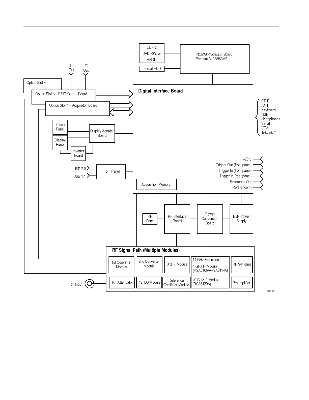
(RTSA) operation. A block diagram of the instrument is shown in this section.
(See Figure 2
General
A processor system controls the RSA6100A instrument. The instrument features
an XGA resolution flat-panel display, a transparent touch-screen, and a front-panel
with direct access to commonly used RTSA features. You can also use the RTSA
with a mouse or other pointing device, and/or a key
The RTSA uses the Microsoft Windows XP operating system.
Signal Path and Processing
-1 on page 2-4.)
board.
RF Signal Path
Acquisition System
Processor System
An RF signal enters the RTSA through a direct coaxial connection (N-type for the
RSA6106A and RSA6114A, 3.5 mm for the RSA6120A) to the input connector.
The RF signal path conditions the input signals and passes them to the acquisition
system for sampling and processing. The RF signal path consists of three
frequency conversion stages, band-limiting filters, and signal level adjustment
stages. The purpose of the RF signal path is to translate a band-limited replica
of a portion of the input signal range (9 kHz to 6.2 GHz for the RSA6106A,
9 kHz to 14 GHz for the RSA6114A, or 9 kHz to 20 GHz for the RSA6120A) to a
intermediate frequency (IF) where it can be sampled by a high dynamic range A/D.
Control of the RF signal path is performed by the processor system.
The acquisition system samples the IF signal and converts it to digital signals.
These digital signals are then filtered numerically and processed either for direct
display or by measurement applications to provide metrics of signal quality
to the user. The acquisition data processing is performed by one of several
field-programmable gate arrays (FPGAs) under control of the processor. The
processor performs measurement applications.
The processor system consists of a PCI-based processor board and a digital
interface board that connects the processor to the acquisition board.
Trigger Inputs
RSA6106A/RSA6114A (S/N B020000 and Above), and RSA6120A Service Manual 2–1
There are two coaxial trigger inputs. One is on the front panel below the display
and the other is on the rear panel. Both trigger inputs connect directly to the digital
interface board. Trigger signals are processed by an FPGA on the digital interface
board. The information from the trigger system is combined with acquisition
data by the processor system.

Theory of Operation
Display Panel
Display system
Touch Panel
Front Panel
The Trigger Out
The trigger out signal comes from the Acquisition Control FPGA via the digital
interface board.
Waveforms, spectral traces, measurement results, and control menus are displayed
on a 10.4 inch, color, active-matrix LCD display with touch panel.
The display system consists of a display adapter board and inverter board, which
sends text and waveform information to the display panel.
The display adapter board sends information from the touch panel to the processor.
The touch panel appears as a USB HID device in the Window Device Manager
tool.
The processor system reads the front-panel switches and encoder. Any changes in
their settings are reported to the processor. The processor also turns the LEDs on
and off.
signal is accessed below the display with a coaxial connection.
The ON/STBY switch passes through the display adapter board, the digital
interface board, and to the processor on the front panel board.
Communication between the processor system and the front panel is performed
over an internal USB connection.
The DVD-RW, removable HDD (hard disk drive), or removable solid-state hard
drive communicate over an IDE connection directly to the processor system.
Rear Panel
The following table describes the connectors available on the RTSA rear panel.
Table 2-1: Rear panel connectors
Name Input or Output Connector type Description
Reference In
Reference Out Output BNC 10 MHz output or loop-through of user
TekLink™
LAN
Input
Input/Output
Input/Output
BNC External time-base reference. See data sheet
for signal quality requirements.
Reference In signal
Proprietary 40-pin
RJ-45
TekLink™ multi-instrument interface connector
10/100/1000baseT Ethernet connector
2–2 RSA6106A/RSA6114A (S/N B020000 and Above), and RSA6120A Service Manual

Theory of Operation
Table 2-1: Rear panel connectors (cont.)
Name Input or Output Connector type Description
USB Input/Output USB Two USB 2.0 connectors
Keyboard Input
VGA Output D-Sub
Serial Input/Output D-Sub Serial communications port (COM2) to
Trigger In Input
Headset
+28 V
GPIB Input/Output
IF Output Output BNC 500 MHz Analog IF Output signal (Option 05)
Digital I/Q Output
Output
Output BNC
PS/2 Keyboard-only PS/2 connector
External monitor connector
processor system
BNC TTL Gate/trigger input signal
3.5 mm stereo E xternal headphone connection
Noise source drive power
IEEE-488
2x50
General Purpose Interface Bus
Two connectors for digital I and Q output
signals. (Option 05)
All connections except the IF Output and Digital I/Q are connected directly to the
digital interface board. The IF Output and Digital I/Q outputs are connected to the
Real-Time I/Q (RTIQ) option board.
Power Supply
Fans
The Power Conversion board provides instrument power. The Power Conversion
board consists of several switching supplies that translate and balance the power
taken from the power supply module.
Power is distributed from the Power Conversion board to both the RF Deck and
the Digital Interface board.
The ON/STBY switch, located on the front panel, controls all of the power to the
instrument except for the part of the circuitry in the standby power supply.
Seven individual fans provide cooling to the RTSA. Three fans are dedicated to
the RF Deck and are controlled by the RF Interface. Two fans provide cooling
for the digital side of the instrument.
The bulk power supply module has an internal fan. Control signals to the power
supply fan are sent through the Power Conversion board from the Digital Interface
board.
A seventh fan is resident on the processor board heat sink, and is controlled by
the Slot PC board.
If Option 200 is installed, eight individual fans provided cooling to the RTSA.
RSA6106A/RSA6114A (S/N B020000 and Above), and RSA6120A Service Manual 2–3
Theory of Operation
Figure 2-1: RSA6100A Series block diagram
2–4 RSA6106A/RSA6114A (S/N B020000 and Above), and RSA6120A Service Manual

Adjustment Procedures


Adjustment Procedure
There are no physical user adjustment procedures for the RSA6100A Series
instruments. However, you can run Alignments from the RSA6100A Series
application. Alignments are software-controlled adjustment procedures.
Running Ali
Alignment Status
gnments
Alignments are adjustment procedures run by the instrument using internal
reference signals and measurements, and do not require any external equipment or
connectio
There are two settings for Alignments:
If Automatically align as needed is selected, alignments run whenever the
spectrum analyzer detects a sufficient change in ambient conditions to warrant
an alignment.
If Run alignments only when "Align Now" button is pressed is selected,
the spectrum analyzer never runs an alignment unless you manually initiate an
alignment using the Align Now button.
NOTE
Automatically align as needed is not enabled.
Whe
screen. If no message is displayed, you can assume that the spectrum analyzer is
properly aligned.
ns.
Automatically align as needed (Auto mode)
Run alignments only when the "Align Now" button is pressed
. There are a few critical adjustments that must run occasionally even if
n the spectrum analyzer needs to run an alignment, it displays a message on
o initiate an alignment:
Initiating an Alignment
RSA6106A/RSA6114A (S/N B020000 and Above), and RSA6120A Service Manual 3–1
T
1. Select Setup > Alignments.
2. Select the Align Now button.
The spectrum analyzer will run an alignment procedure. Status messages are
displayed while the alignment procedure is running. If the instrument fails the
alignment procedure, an error message will be displayed. If the instrument fails
an alignment, run Diagnostics (Tools > Diagnostics) to see if you can determine
why the alignment failed.
NOTE. While an alignment is running, both the IF and IQ outputs are disabled.

Adjustment Procedure
Alignments During
Warm-Up
Alignments During Normal
Operation
Alignments Are Not
Calibrations
Alignments are
oscillator alignments) because default alignment values are used, (if Auto mode is
selected). During the specified period for warm-up, the instrument performance
is not warranted.
Once the spectrum analyzer reaches operating temperature, a full alignment is then
run every two hours (for up to two minutes). Alignments can run more frequently
if the operating temperature changes. If an alignment becomes necessary during
a measurement cycle (if Auto mode is selected), the measurement is aborted
and an alignment procedure is run. Once an alignment procedure is completed,
the measu
Alignments are adjustment procedures run by the instrument using internal
referen
Tektronix service center and require the use of traceable test equipment (signal
sources and measuring equipment) to verify the performance of the instrument.
ce signals and measurements. Calibrations can only be performed at a
not run during the 20 minute warm-up period (except, for the RF
rement cycle restarts.
3–2 RSA6106A/RSA6114A (S/N B020000 and Above), and RSA6120A Service Manual
 Loading...