

Page 1

xx
RSA6100A Series
Real-Time Spectrum Analyzers
RSA6UP Option 200
ZZZ
Enhanced DPX and Triggers
Instructions
www.tektronix.com
P075098700*
*
075-0987-00
Page 2

Copyright © Tektronix. All rights reserved. Licensed software products are owned by Tektronix or its subsidiaries
or suppliers, and are protected by national copyright laws and international treaty provisions.
Tektronix products are covered by U.S. and foreign patents, issued and pending. Information in this publication
supersedes that in all previously published material. Specifications and price change privileges reserved.
TEKTRONIX and TEK are registered trademarks of Tektronix, Inc.
Contacting Tektronix
Tektronix, Inc.
14200 SW Karl Braun Drive
P.O. B o x 5 0 0
Beaverto
USA
For product information, sales, service, and technical support:
n, OR 97077
In North America, call 1-800-833-9200.
Worl dwid e, vis it www.tektronix.com to find contacts in your area.
Page 3

Table of Contents
Service Safety Summary.......................................... ................................ ................. 1
Kit Description........................................... ................................ ........................... 2
Products ................................ ................................ ................................ ......... 2
Kit Parts Li
Installation Instructions............................................................................................ 3
Minimum Tool and Equipment List ........ ................................ ................................. 3
Remove Cosmetic Top Cover ................................................................................ 3
Remove the RTT/DPX Board and Bracket .. ................................ ............................... 5
Install the RTT/DPX (Option 200) Board and CPU Bracket ............................................ 12
Reinsta
Software Installation.......................................................................................... 16
st .............. ................................ ................................ ..................... 2
ll Cosmetic Top Cover............................................................................... 16
RSA6100A Series RSA6UP Option 200 Upgrade i
Page 4

Table of Contents
ii RSA6100A Series RSA6UP Option 200 Upgrade
Page 5

Service Safety Summary
Only qualified personnel should perform service procedures. Read this Service
Safety Summary and the General Safety Summary located in the RSA6100A
Service manu
service procedures.
Do Not Service Alone. Do not perform internal service or adjustments of this
product unless another person capable of rendering first aid and resuscitation is
present.
Disconnect Power. To avoid electric shock, switch off the instrument power, then
disconnect the power cord from the mains power.
UseCareWhenServicingWithPowerOn. Dangerousvoltagesorcurrentsmay
exist in this product. Disconnect power, remove battery (if applicable), and
nect test leads before removing protective panels, soldering, or replacing
discon
components.
al (Tektronix part number 071-1914-XX) before performing any
To avo
id electric shock, do not touch exposed connections.
RSA6100A Series RSA6UP Option 200 Upgrade 1
Page 6

Kit Description
Kit Description
Products
Kit Parts List
This kit describes the installation of the RTT/DPX (Option 200) Board and
the CPU bracket in an RSA6100A Series Real-Time Spectrum Analyzer. The
RTT/DPX (Opt
ion 200) board enables Enhanced DPX and Triggers functionality,
and replaces the RTT/DPX board in the instrument.
NOTE. You may not need to install the CPU bracket, check your instrument to
verify which bracket is installed. (See Figure 2 on page 5.)
RSA6100A Series. All instruments
Quantity Part number Description
1 ea 863-02
1 ea 407-5
1 ea 075-0
1 ea 020-2715-XX
1 ea 063-3930-XX
1
You may or may not need to install the CPU bracket, check your instrument.
73-XX
142-XX
987-00
CIRCUIT BD ASSY;
RTT/DPX,PB-FREE,870027300
FUNCTI
TESTED,389367101 WIRED, OPTION 200
1
BRACKET,SUPPORT; SLOT PC
INSTRUCTION,KIT; DPX BOARD
INSTALLATION FOR RSA6UP 200,PRINTED
PACKAGING KIT; INSTRUMENT SOFTWARE
SOFTWARE;DOCUMENTS CD
ONALLY TESTED,878027300
2 RSA6100A Series R SA6UP Option 200 Upgrade
Page 7
Installation Instructions
This section contains all procedures needed to install the RTT/DPX (Option
200) Board, the CPU bracket, and the product software in RSA6100A Series
instruments
Minimum Tool and Equipment List
The following tools are required to remove the instrument covers, the bracket,
and reinstall the VGA cable. All tools are standard tools that should be readily
available.
Table 1: Tools required for installation
Item
no. Name Description
1
2
3
4
5
.
Screwdriver
handle
(magnetic)
T-15 TORX
tip
5/32-in. hex
wrench
T-10 TORX
tip
3/16-in. nut
driver
Installation Instructions
Torque driver handle. Accepts 1/4-in. hex-head driver tips
TORX-driver tip for T-15 size screws on the instrument covers
Hex wrench to remove Allen head screws at front of top cover
TORX-driver tip for T-10 size screw heads on the VGA cable
connector
Nut driver to remove the hex posts from the bracket (Slot PC
board)
Optional: A torque wrench helps to ensure reliable connections to meet the
nominal torque values that may be listed in these instructions.
These instructions are for qualified service personnel who are familiar
with servicing the product. If you need further details for disassembling or
reassembling the product, refer to the product service manual, Tektronix part
number 071-1914-xx.
Remove Cosmetic Top Cover
NOTE. Right-side or left-side references in these instructions assume you a re
viewing the instrument from the front panel.
WAR NI NG . To avoid electric shock which may result in injury or loss of life, switch
off the instrument power, then disconnect the power cord from the mains power.
RSA6100A Series RSA6UP Option 200 Upgrade 3
Page 8

Installation Instructions
1. Remove the powe
2. If it is installed, pull the front protective cover off the instrument.
3. Remove the two T-15 TORX-driver screws that secure the plastic carrying
handle to the s ide of the instrument. (It is not necessary to remove the black
metal handl
4. Remove four T-15 screws along each side that secure the top and bottom
covers to th
front edge of the top cover (next to the folding handles).
5. Remove the
cover by pulling straight back about 1 inch. Then pull the sides of the top
cover outward, flexing them slightly to clear the instrument chassis, and pull
it away from the instrument.
6. Remove the 18 T-15 screws that secure the top internal cover to the chassis,
and then remove the top internal cover from the instrument.
rcord.
es.) (See Figure 1.)
e instrument, and remove two 5/32-in. Allen head screws near the
top cover (leave the bottom cover in place). Remove the top
igure 1: Removing the Cosmetic Top Cover
F
4 RSA6100A Series R SA6UP Option 200 Upgrade
Page 9
Installation Instructions
Remove the RTT
/DPX Board and Bracket
NOTE. The slot numbers are labeled on the Digital Interface board by the
connectors.
1. Remove the RTT/DPX board from the instrument (Slot 5). Discard this board
as recommended by your company policy.
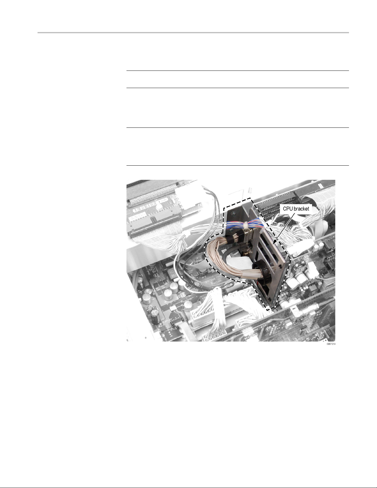
NOTE. Chec
(See Figure 2.) If it does, skip the remaining steps in this section and install the
RTT/DPX (Option 200) board. Beginning with step 10. (See page 15.)
If you need to install the CPU bracket, follow these steps.
k if your instrument already has the CPU bracket installed as shown.
Figure 2: CPU bracket installed on Slot PC board
RSA6100A Series RSA6UP Option 200 Upgrade 5
Page 10
Installation Instructions
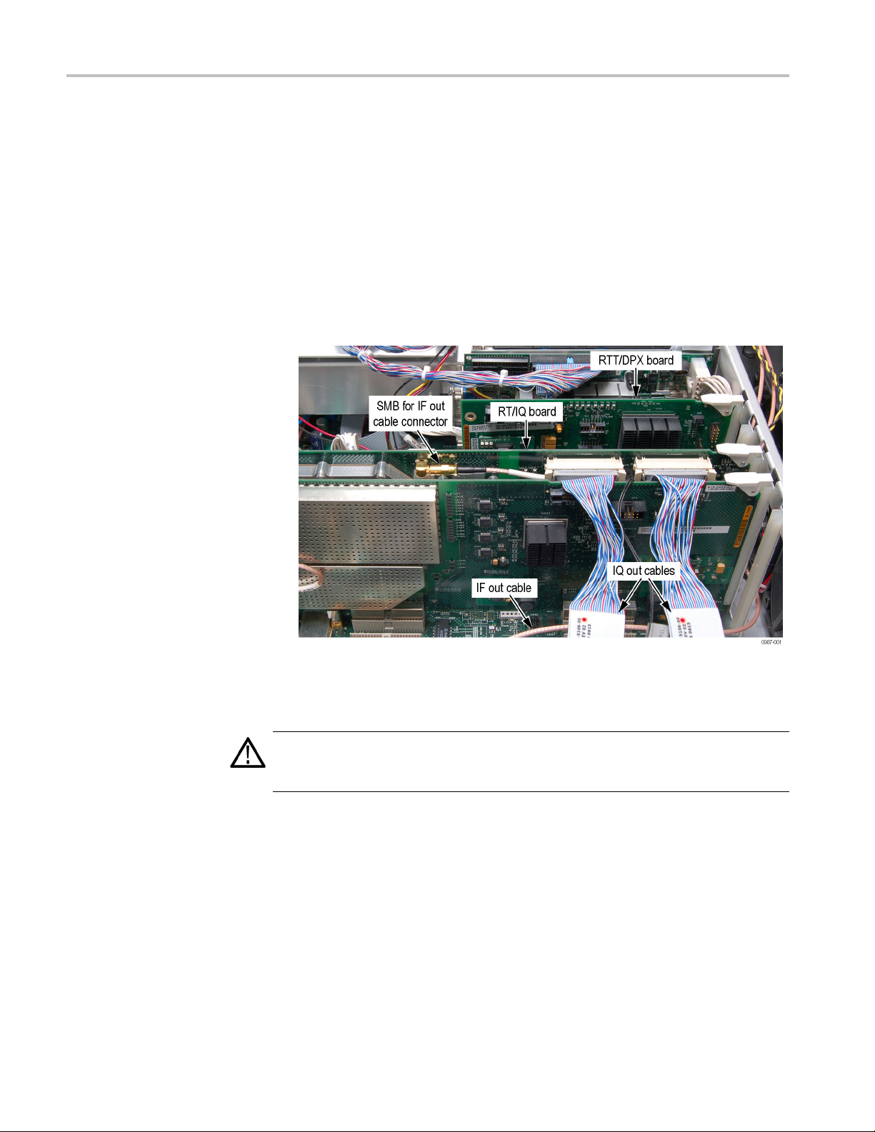
2. If Option 05 (RT
the RT/IQ board to gain sufficient clearance to remove the Slot PC board:
a. Use the board e
b. Disconnect the IQ Out cables from the RT/IQ board, and lay them over
the rear pan
c. Disconnect the IF Out cable from the SMB connector on the RT/IQ board.
Note the rou
d. Disconnect the RT/IQ ground cable from its two-pin connector. Note the
routing of
/IQ board) is installed in Slot 3, disconnect the cabling from
jectors to disconnect the RT/IQ board connector.
el.
ting of this cable for reinstallation.
this cable for reinstallation.
Figure 3: Removing the cables from RT/IQ board
3. Remove the RT/IQ board from the instrument.
CAUTION. Do not remove the Acquisition board from the instrument. The
calibration of the instrument may be compromised, requiring a return to the
factory for recalibration.
6 RSA6100A Series R SA6UP Option 200 Upgrade
Page 11

Installation Instructions
4. Disconnect the
on the IDE cable) from the Slot PC board.
Figure 4: IDE cable location
NOTE. Only disconnect the following cables from the Digital Interface Board. Do
not disconnect these cables from the Slot PC board (except for the Ethernet cable).
5. Disconnect these cables from the Digital Interface board:
Ethern
IDE cable to the HDD and/or DVD connector (Blue connector
et cable from J20 (PC NETWORK) and the Slot PC board
VGA cable from J28 (PC VIDEO)
Figure 5: Cables J20 and J28 locations
RSA6100A Series RSA6UP Option 200 Upgrade 7
Page 12
Installation Instructions
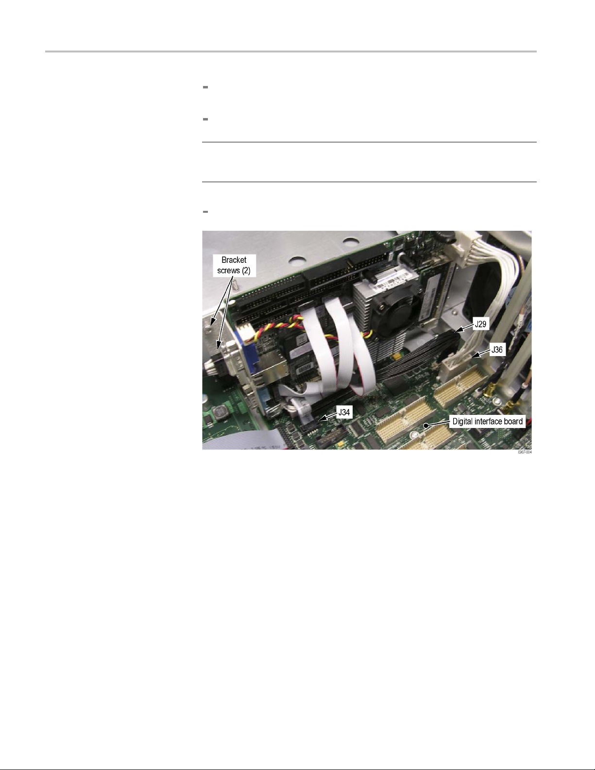
12-pin Power ca
either side of the connector to remove the cable.
40-pin cable f
NOTE. The 40-pin cable (J29) is difficult to connect and seat in the connector
on the Digital Interface board. When reinstalling, make sure that the
connector is fully seated.
10-pin ribbon cable from J34 (AC97 IN).
ble from J36 (PC POWER). Hold down the latches on
rom J29 (LVDS VIDEO IN). See note below.
Figure 6: Cables J29, J34, and J36 locations [being updated, Mel]
6. Remove the two screws that secure the bracket to the side of the chassis using
a T-15 driver. (See Figure 6.)
7. Lift the Slot PC board, to disengage the PCI connector from the Digital
Interface board, but do not remove it completely from the instrument yet.
8 RSA6100A Series R SA6UP Option 200 Upgrade
Page 13
Installation Instructions
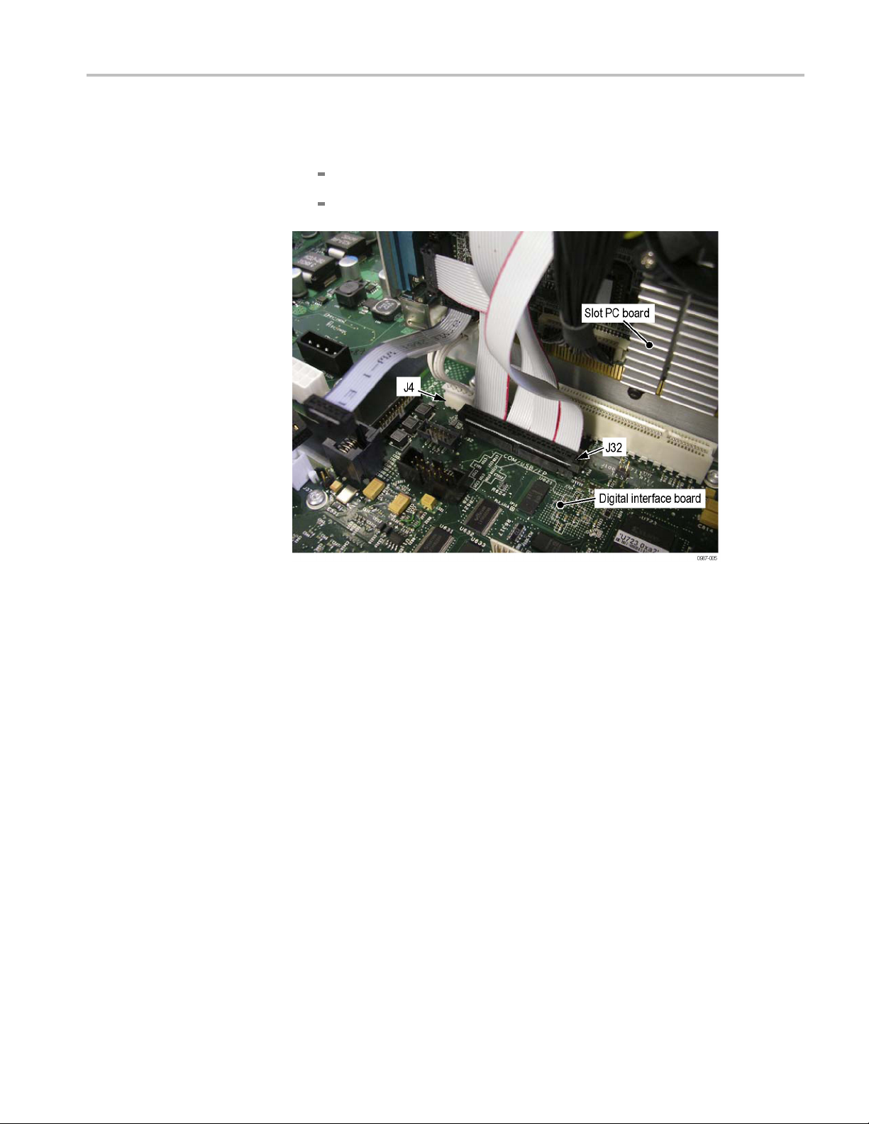
8. Disconnect the
Figure 7.)
44-pin ribbon
5-pin cable from J4.
se cables from the Digital Interface board as shown. (See
cable from J32 (COM/USB/FP).
Figure 7: Cables J4 and J32 locations
RSA6100A Series RSA6UP Option 200 Upgrade 9
Page 14

Installation Instructions
9. Remove the Slot
NOTE. If you accidently remove the J32 cable from the Slot PC board, reconnect
the ribbon cables as shown.
PC board from the instrument.
Figure 8: Ribbon cable locations (for J32) on the Slot PC board
10 RSA6100A Series RSA6UP Option 200 Upgrade
Page 15

Installation Instructions
10. Remove the exis
Using a T-10 driver, remove the two screws from the VGA video cable
on the bracket
Disconnect the VGA video cable from the socket.
Using the 3/16” nut driver, remove the four hex posts that attach the
RS232 connector and VGA connector to the bracket.
ting bracket from the Slot PC board:
.
Figure 9: Slot PC board with older bracket
RSA6100A Series RSA6UP Option 200 Upgrade 11
Page 16

Installation Instructions
Install the RT
T/DPX (Option 200) Board and CPU Bracket
NOTE. Check if your instrument already has the CPU bracket installed as shown.
If it does, skip the following steps and install the RTT/DPX (Option 200) board.
Go to step 10. (See page 15.)
If you need to install the CPU bracket, follow these steps.
1. Install the CPU bracket on the Slot PC board as shown using the existing hex
posts (4) disconnected in step 10 of the removal procedure. (See page 11.)
Figure 10: CPU Bracket and Slot PC board
2. Install the Slot PC board by reconnecting the cables disconnected in steps 4
through 5 of the removal procedure. (See page 7.)
12 RSA6100A Series RSA6UP Option 200 Upgrade
Page 17
Installation Instructions
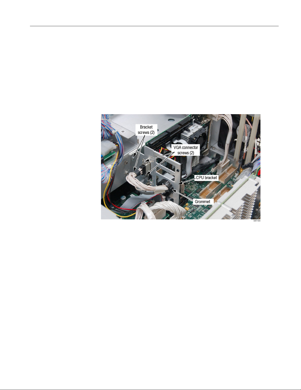
3. Using a T-15 wre
bracket on the chassis (torque to 8.0 in-lb). (See Figure 11.)
4. Dress the VGA c
and connect the VGA cable to the VGA connector on the CPU bracket.
5. Using a T-10
VGA connector to the hex posts on the CPU bracket (torque to 5.5 in-lb).
6. Dress the Et
bracket and connect the Ethernet cable to the Ethernet connector on the CPU
bracket.
nch and the two existing bracket screws, install the CPU
able through the black plastic grommet on the CPU bracket
wrench and the two existing VGA-connector screws, secure the
hernet cable through the black plastic grommet on the CPU
Figure 11: CPU bracket installed on the chassis
RSA6100A Series RSA6UP Option 200 Upgrade 13
Page 18

Installation Instructions
7. Reconnect the I
8. Using a cable tie, rebundle the IDE cables to the top of the CPU bracket (on
the smooth edg
Figure 1
2: IDE cables and cable tie location (for Options 06 and 08)
DE cable to the Slot PC board. (See Figure 12.)
e).
Figure 13: IDE cables and cable tie locations (for Option 07)
14 RSA6100A Series RSA6UP Option 200 Upgrade
Page 19

Installation Instructions
9. If the RT/IQ (Op
disconnected in step 2. (See page 5, Remove the RTT/DPX Board and
Bracket.) (Reseat the RT/IQ board into the Digital Interface board connector.
Be careful not to bend the pins on the Digital Interface board when seating
the RT/IQ board.)
Figure 14: RT/IQ (Option 05) and RTT/DPX (Option 200) boards installed.
tion 05) board was installed in Slot 3, reconnect the cables
CAUTION. To prevent damage to the connector on the Digital Interface board,
gently slide and then connect the RTT/DPX (Option 200) board into the Digital
face board connector.
Inter
10. Install the RTT/DPX (Option 200) board (Slot 5). Be careful not to bend
ins on the Digital Interface board when seating the RTT/DPX (Option
the p
200) board.
11. Rei
nstall the top internal cover. (See Figure 1 on page 4.)
Place the top internal cover onto the instrument, aligning the two
otrusions on the cover with the two slots in the chassis.
pr
Replace the 18 T-15 screws that secure the top internal cover to the
hassis. Torque these screws to 8.0 in/lb.
c
RSA6100A Series RSA6UP Option 200 Upgrade 15
Page 20

Installation Instructions
Reinstall Cos
metic Top Cover
Software Installation
Reinstall the top and bottom covers. (See Figure 1 on page 4.)
1. Place the instrument on the rear feet, so the front panel is facing up and the
top is toward you.
2. Place the top cover over the top of the instrument and slide it toward the
front panel. Make sure that the top cover wraps around the flanges on the
rear panel on all three sides.
3. Reinstall the four 5/32-in. Allen headscrews(twooneachside)nearthe
front edge of the top cover (next to the folding handles) that secure the top
cover to t
4. Align the four screw holes on each side in the top and bottom covers with the
holes in
these screws to 8.0 in/lb.
5. Positi
instrument, and install the two T-15 screws that secure it in place. Torque
these screws to 8.0 in/lb.
he instrument.
the chassis, and install eight T-15 screws, four on each side. Torque
on the plastic carrying handle and its bracket on the right side of the
Use the RSA6100A Series product software disc to reinstall the spectrum analyzer
product software if your instrument software version is earlier than the software
version listed on the disc.
1. If a keyboard is not installed, connect one to the instrument (the supplied
accessory keyboard plugs into the USB connector).
2. If your instrument has a removable hard drive (Option 06) or a solid-state hard
drive (Option 08), connect a USB external DVD drive to the instrument.
3. Power on the instrument.
16 RSA6100A Series RSA6UP Option 200 Upgrade
Page 21

Installation Instructions
Install Option K ey
4. After the instr
application (Select File > Exit).
5. Insert the Product Software disc in the front-panel DVD drive (or external
drive), and close the drive tray.
6. The Setup Wizard starts. Follow the instructions to install the product
software.
CAUTION. When the Setup Wizard displays the Select Installation Folder
screen, the Setup Wizard allows you to select whether the software is installed
for Everyone or Just me. Always select Everyone to ensure proper software
operation.
7. When the product software installation is complete, the Installation
Complete screen appears. Click Close to exit the Setup Wizard.
8. When the RSA6100A Setup dialog box appears, click OK.
The Product Software is now ready to use.
To activate the enhanced DPX and Trigger functionality option:
ument completes booting up, exit the product software
1. In the spectrum analyzer application, select Tools > Instal l Upgrades. The
Install Upgrade wizard starts, as shown in Figure 1. Click Continue.
Figure 15: Starting the option upgrade
2. The Install Upgrade Enter Key screen appears as shown.
RSA6100A Series RSA6UP Option 200 Upgrade 17
Page 22

Installation Instructions
Figure 16: Entering the option installation key
3. Type the option installation key into the empty text box and click Continue.
An Inst
allation Success dialog box opens, as shown.
Figure 17: Upgrade success notification
18 RSA6100A Series RSA6UP Option 200 Upgrade
Page 23

Installation Instructions
Installing the Option Key
Label
4. Click Close. Ex
feature.
5. Select Help > A
6. In the installed Options window verify that Option 200 is listed.
7. Click Ok.
Place the new option key label over the existing label on the instrument rear panel.
This completes the installation of the Enhanced DPX and Trigger functionality
(Option 200) upgrade kit.
<End of Document>
it and restart the RSA6100A application to enable the new
bout Tektronix Real Time Spectrum Analyzer.
RSA6100A Series RSA6UP Option 200 Upgrade 19
 Loading...