

Page 1

xx
RSA6100B Series Real-Time Signal Analyzers and
RSA5100A Series Real-Time Signal Analyzers
Option 53 Memory Extension, 4 GB Acquisition Memory Total
ZZZ
Upgrade
Instructions
www.tektronix.com
P071287901*
*
071-2879-01
Page 2

Copyright © Tektronix. All rights reserved. Licensed software products are owned by Tektronix or its subsidiaries
or suppliers, and are protected by national copyright laws and international treaty provisions.
Tektronix products are covered by U.S. and foreign patents, issued and pending. Information in this publication
supersedes that in all previously published material. Specifica tions and price change privileges reserved.
TEKTRONIX and TEK are registered trademarks of Tektronix, Inc.
Contacting Tektronix
Tektronix, Inc.
14150 SW Karl Braun Drive
P.O. B o x 5 0 0
Beaverto
USA
For product information, sales, service, and technical support:
n, OR 97077
In North America, call 1-800-833-9200.
Worl dwid e, v isit www.tektronix.com to find contacts in your area.
Page 3

Table of Contents
Service Safety Summary.......................................... ................................ ................. 1
Kit Description........................................... ................................ ........................... 2
Products ................................ ................................ ................................ ......... 2
Kit Parts Li
Installation Instructions............................................................................................ 3
Minimum Tool and Equipment List ........ ................................ ................................. 3
Remove Cosmetic Top Cover ................................................................................ 3
Replace the Existing Acquisition Memory. .... . . .... . ..... . ..... . ... . . ..... . ..... . ... . . . .... . ..... . ..... . .. 5
Reinstall Cosmetic Top Cover................................................................................ 7
Option K
st .............. ................................ ................................ ..................... 2
ey Installation ....................................................................................... 7
RSA6UP & RSA5UP Option 53 Upgrade i
Page 4

Table of Contents
ii RSA6UP & RSA5UP O ption 53 Upgrade
Page 5

Service Safety Summary
Only qualified personnel should perform service procedures. Read this Service
Safety Summary and the General Safety Summary located in your instrument’s
Service manu
the RSA5100A Service manual part number is 077-0522-XX) before performing
any service procedures.
Do Not Service Alone. Do not perform internal service or adjustments of this
product unless another person capable of rendering first aid and resuscitation is
present.
Disconnect Power. To avoid electric shock, switch off the instrument power, then
disconnect the power cord from the mains power.
UseCareWhenServicingWithPowerOn. Dangerousvoltagesorcurrentsmay
n this product. Disconnect power, remove battery (if applicable), and
exist i
disconnect test leads before removing protective panels, soldering, or replacing
components.
To avoid electric shock, do not touch exposed connections.
al ( the RSA6100B Service manual part number is 077-0648-XX and
RSA6UP & RSA5UP Option 53 Upgrade 1
Page 6

Kit Description
Kit Description
Products
Kit Parts List
This kit describes the installation of the Option 53 Memory Extension in an
RSA6100B Series or RSA5100A Series Real-Time Signal Analyzer.
RSA6100B Series. All instruments
RSA5100A Series. All instruments
Quantity Part number Description
1 ea 071-2879-01
1 ea 167–1473-XX
1ea
1ea
1
NS – Not saleable
NS
NS
1
1
RSA5UP OPTION 53 UPGRADE
INSTRUC
IC, MEMO
667MHZ, MT16HTS51264HY-667A1, SODIMM
200
DATA SHEET; SOFTWARE OPTION KEY
AUTHO
KITS
LABEL, MANUFACTURED; OPTION KEY
UPGRADE LABEL 2.100 X 2.700, SAFETY
CONT
TIONS
RY, D RA M; 512MX64, DDR2,
RIZATION CERTIFICATE, UPGRADE
ROLLED
2 RSA6UP & RSA5UP Option 53 Upgrade
Page 7

Installation Instructions
This section contains all procedures needed to install Option 53 Memory
Extension (4 GB Acquisition Memory Total) in RSA6100B Series and RSA5100A
Series instr
Minimum Tool and Equipment List
The following tools are required to install the Option 53 upgrade. All tools are
standard tools that should be readily available.
Table 1: Tools required for installation
Item
no. Name Description
1
2
4
uments.
Screwdriver
handle
(magnetic)
T15 TORX
tip
T20 TORX
tip
Installation Instructions
Torque driver handle. Accepts 1/4-in. hex-head driver tips
TORX-driver tip for T15 size screws on the i nstrument covers
TORX driver tip for T20 size screw heads
Optional: A torque wrench helps to ensure reliable connections to meet the
nominal torque values that may be listed in these instructions.
These instructions are for qualified service personnel who are familiar
with servicing the product. If you need further details for disassembling or
reassembling the product, refer to the product service manual. Service manuals
can be downloaded from the web at www.tektronix.com/manuals. Search by
model number to find the service manual for your instrument.
Remove Cosmetic Top Cover
NOTE. Right-side or left-side references in these instructions assume you are
viewing the instrument from the front panel.
WAR NI NG . To avoid electric shock which may result in injury or loss of life, switch
off the instrument power, then disconnect the power cord from the mains power.
1. Remove the power cord.
2. If it is installed, pull the front protective cover off the instrument.
RSA6UP & RSA5UP Option 53 Upgrade 3
Page 8

Installation Instructions
3. Remove the two T
handle to the s ide of the instrument. (It is not necessary to remove the black
metal handles.) (See Figure 1.)
4. Remove four T15 screws along each side that secure the top and bottom
covers to the instrument, and remove two T20 screws near the front edge of
the top cover (next to the folding handles).
5. Remove the top cover (leave the bottom cover in place). Remove the top
cover by pulling straight back about 1 inch. Then pull the sides of the top
cover outward, flexing them slightly to clear the instrument chassis, and pull
it away from the instrument.
6. Remove the 18 T15 screws that secure the top internal cover to the chassis,
and then remove the top internal cover from the instrument.
15 TORX-driver screws that secure the plastic carrying
Figure 1: Removing the cosmetic top cover
4 RSA6UP & RSA5UP Option 53 Upgrade
Page 9
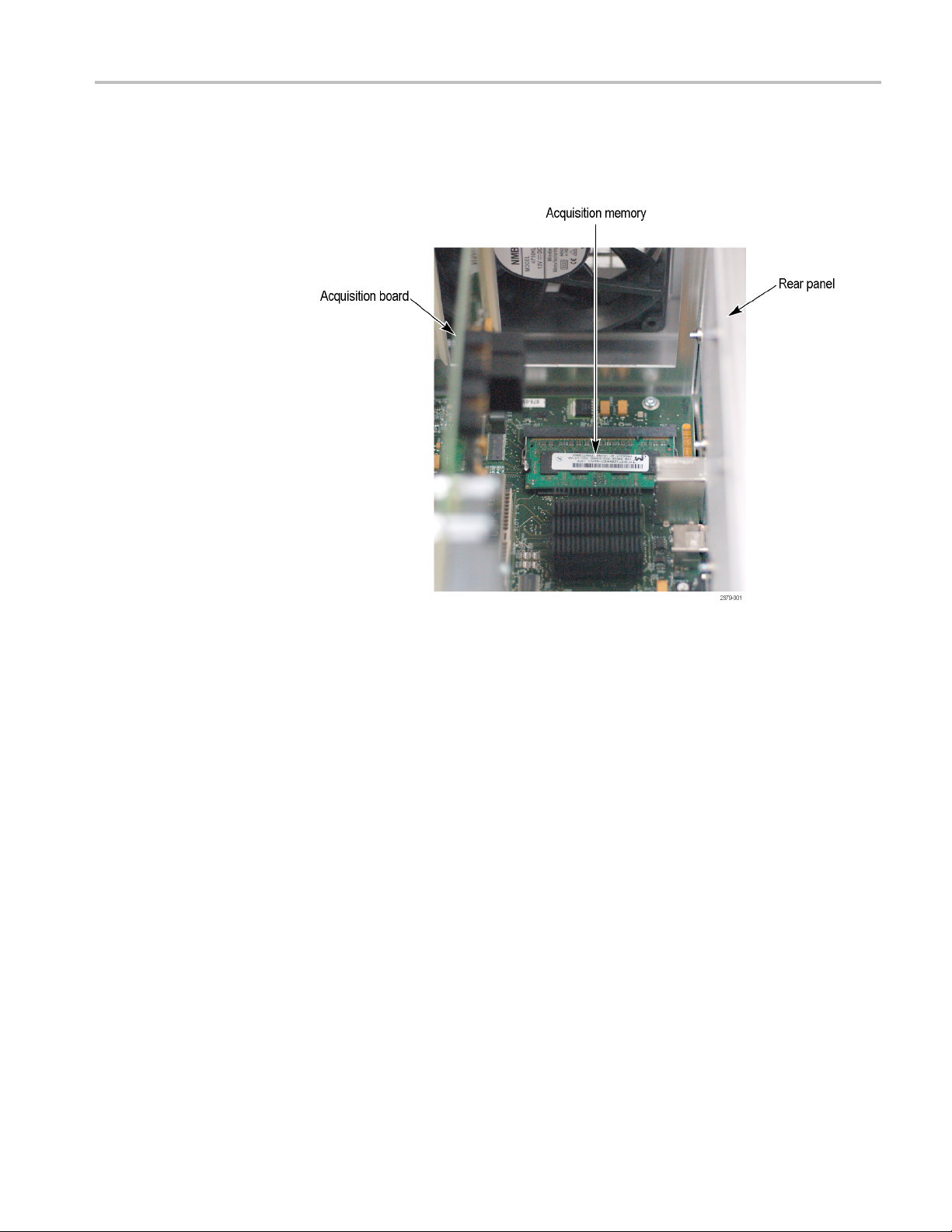
Replace the Existing Acquisition Memory
The acquisition memory is located near the rear panel, on the left side.
Installation Instructions
RSA6UP & RSA5UP Option 53 Upgrade 5
Page 10

Installation Instructions
1. Use the ejector
module. Place the memory module into a static-shielded bag.
2. Insert th
the gold “fingers” are fully seated. Then rotate the module down toward the
board until the latches click into place.
3. Reinstall the top internal cover. (See Figure 1 on page 4.)
e new memory module at an approximately 45° angle, making sure
Place t
protrusions on the cover with the two slots in the chassis.
latches to release the existing 1 GB acquisition memory
he top internal cover onto the instrument, aligning the two
ce the 18 T15 screws that secure the top internal cover to the chassis.
Repla
Torque these screws to 8.0 in/lb.
6 RSA6UP & RSA5UP Option 53 Upgrade
Page 11

Installation Instructions
Reinstall Cos
metic Top Cover
Option Key Installation
Reinstall the top and bottom covers. (See Figure 1 on page 4.)
1. Place the instrument on the rear feet, so the front panel is facing up and the
topistowardyou.
2. Place the top cover over the top of the instrument and slide it toward the
front panel. Make sure that the top cover wraps around the flanges on the
rear panel on all three sides.
3. ReinstallthefourT20Torxheadscrews(twooneachside)nearthefront
edge of the top cover (next to the folding handles) that secure the top cover to
the instr
4. Align the four screw holes on each side in the top and bottom covers with the
holes in
these screws to 8.0 in/lb.
5. Positi
instrument, and install the two T15 screws that secure it in place. Torque
these screws to 8.0 in/lb.
ument. Torque these screws to 8.0 in/lb.
the chassis, and install eight T15 screws, four on each side. Torque
on the plastic carrying handle and its bracket on the right side of the
To enter the new option key:
1. In the signal analyzer application, select Tools > Install Upgrades.The
Install Upgrade wizard starts. (See Figure 2.) Click Continue.
Figure 2: Starting the option upgrade
2. The Install Upgrade Enter Key screen appears as shown.
RSA6UP & RSA5UP Option 53 Upgrade 7
Page 12

Installation Instructions
Figure 3: Entering the option installation key
3. Type the option installation key into the empty text box and click Continue.
An Installation Success dialog box appears after you click Continue.
Installing the Option Key
Label
4. Click Close. Exit and restart the RSA application to enable the new feature.
5. Select Help > About Tektronix Real Time Signal Analyzer.
6. In the installed Options window, verify that Option 53 is listed.
7. Click O
Place the new option key label over the existing label on the instrument rear panel.
This completes the installation of the Option 53 Memory Extension, 4 GB
Acquisition Memory Total Upgrade kit.
End of Document
K.
8 RSA6UP & RSA5UP Option 53 Upgrade
 Loading...