

Page 1

xx
RSA5100A Series Real-Time Signal Analyzers
RSA5UP Option 56, Option 57, and
ZZZ
Option 59 Upgrades
Instructions
www.tektronix.com
P071286300*
*
071-2863-00
Page 2

Copyright © Tektronix. All rights reserved. Licensed software products are owned by Tektronix or its subsidiaries
or suppliers, and are protected by national copyright laws and international treaty provisions.
Tektronix products are covered by U.S. and foreign patents, issued and pending. Information in this publication
supersedes that in all previously published material. Specifications and price change privileges reserved.
TEKTRONIX and TEK are registered trademarks of Tektronix, Inc.
Contacting Tektronix
Tektronix, Inc.
14150 SW Karl Braun Drive
P.O. B o x 5 0 0
Beaverto
USA
For product information, sales, service, and technical support:
n, OR 97077
In North America, call 1-800-833-9200.
Worl dwid e, v isit www.tektronix.com to find contacts in your area.
Page 3

Table of Contents
Service Safety Summary.......................................... ................................ ................. 1
Kit Description........................................... ................................ ........................... 2
Products ................................ ................................ ................................ ......... 2
Kit Parts Li
Removing the Installed Drives.................................................................................... 5
Minimum Tool and Equipment List ...................... ................................ ................... 5
Removing a Removable Hard Disk Drive (Option 56).................................................... 5
Removing a DVD Drive and Internal Hard Drive (Option 57 or Option 59) .............. ............. 6
Installing New Drive Options . .... . ..... . .... . ..... . ..... ..... . ..... . .... . ..... . ... . . ..... . .... . ..... . ..... ..... . 10
Install
Installing Option 57: DVD-R/W Drive and Internal Hard Drive..... . ..... . .... . ..... . ... . . ..... . .... . . 12
Installing Option 59: Internal Hard Drive .... . .... . . .... . ..... . ..... . ... . . ..... . ..... . ... . . . .... . ..... . ... 19
st .............. ................................ ................................ ..................... 2
ing Option 56: Removable Hard Disk Drive ....................................................... 10
RSA5100A Series Options 56, 57, and 59 Upgrades i
Page 4

Table of Contents
ii RSA5100A Series Options 56, 57, and 59 Upgrades
Page 5

Service Safety Summary
Only qualified personnel should perform service procedures. Read this Service
Safety Summary and the General Safety Summary located in the RSA5100A
Real-Time Si
before performing any service procedures.
Do Not Service Alone. Do not perform internal service or adjustments of this
product unless another person capable of rendering first aid and resuscitation is
present.
Disconnect Power. To avoid electric shock, switch off the instrument power, then
disconnect the power cord from the mains power.
UseCareWhenServicingWithPowerOn. Dangerousvoltagesorcurrentsmay
exist in this product. Disconnect power, remove battery (if applicable), and
discon
components.
gnal Analyzer Service manual (Tektronix part number 077-0522-XX)
nect test leads before removing p rotective panels, soldering, or replacing
To avo
id electric shock, do not touch e xposed connections.
RSA5100A Series Options 56, 57, and 59 Upgrades 1
Page 6

Kit Description
Kit Description
Products
This kit describes the installation of each of the three hard drive upgrade options
(Option 56, Option 57, and Option 58) in an RSA5100A Series Real-Time Signal
Analyzer.
Kit Parts List
RSA5UP Option 56
Removab
le Hard Drive
Parts List
RSA5100A S e
The follo
ries. All serial numbers.
wing parts lists detail the parts included with your upgrade kit. The parts
shipped in your kit depend on the kit option you ordered.
y
Quantit
1ea
1 ea 020-3068-XX
1 ea 071-2191-XX
1 ea 071-2863-00
2 e a 211
4 ea 211-1081-00
a
1e
1 ea 407-5473-00
1 ea 650-5353-00
Part num
40
ber
NS SOFTWAR
-1050-00
7-5337-00
Descrip
AUTHENTICITY); MICROSOFT WINDOWS 7
PRO FOR EMBEDDED SYSTEMS 32/64BIT
SOFTWARE, O S RESTORE KIT, WIN XP
EMBED
MANUA
SUPPLEMENTAL INFORMATION SHEET FOR
THE PEOPLES REPUBLIC OF CHINA; CHINA
ROHS
MANU
INSTALLATION INSTRUCTIONS
SCREW, MACHINE; 6-32 X 0.312 L, PNH,
STEEL, ZINC FINISH, T15
SCREW, MACHINE; M3 X 0.5 X 3.5MM,
FL
RELIEVED, PHL, ZINC PLATED STEEL
BRACKET, RHDD; SATA COMBO CABLE
RETENTION
BRACKET; HARD DRIVE 2.5 INCH
R
DRIVE ASSEMBLY; REMOVABLE HARD
DRIVE, PROGRAMMED, RSA5XXX SERIES
tion
E COA (CERTIFICATE OF
DED, RSA51XXA SERIES
L, TECH; SVCPT-UPG; TEKTRONIX
AL, TE CH: RSA5K 56, 57, 59
AT WAFER HD W/SERRATIONS STRESS
EMOVABLE
2 RSA5100A Series Options 56, 57, and 59 Upgrades
Page 7

Kit Description
RSA5UP Option
57 Internal
HDD and DVD-R / CD-RW
Parts List
Quantity Part number Description
1ea
1 ea 020-3068-XX
1 ea 071-2191-XX
1 ea 071-2863-00
1 ea 119-7678-00
1 ea 174-5650-00
1 ea 200-5143-00
4ea 210-1543-01
4 e a 211-0
4 ea 211-1070-00
4 ea 348-1835-00
1 ea 407-5476-00
1 ea 650-5352-00
NS SOFTWARE COA (CERTIFICATE OF
AUTHENTICITY
PRO FOR EMBEDDED SYSTEMS 32/64BIT
SOFTWARE, OS RESTORE KIT, WIN XP
EMBEDDED, RSA51XXA SERIES
MANUAL, TECH; SVCPT-UPG; TEKTRONIX
SUPPLEMENT
THE PEOPLES REPUBLIC OF CHINA; CHINA
ROHS
MANUAL, TECH: RSA5K 56, 57, 59
INSTALLA
OPTICAL,
MB/SEC, 650MEG/8.5GIG, SATA/ATAPI;TEAC
MODEL DV-W28S-V93.
CABLE, SATA-DVD, DATA AND POWE R,
CONTROLLED
DVD
, SHOULDER, SPECIAL; 6-32 (USE
OGRAMMED 1197524XX, , RSA5XXX
510-00
SAFETY
COVER;
SCREW
WITH VIBE ISOLATION GROMMETT)
SCREW, MACHINE; 6-32 X 0.375, PNH, ZINC
PLATED STEEL, T15
SCREW; M2 X .4 X 2MM, PNH, PHL, STL NI PL
GROMMET; VIBRATION ISOLATION
BRACKET, DVD DRIVE
DRIVE ASSEMBLY; INTERNAL FIXED DRIVE,
PR
SERIES
); MICROSOFT WINDOWS 7
AL INFORMATION SHEET FOR
TION INSTRUCTIONS
CD-RW/DVD-R/RW DVD+R/RW, 16.7
RSA5UP Option 59 Internal
Hard Disk Drive
Quantity Part number Description
1ea
1 ea 071-2191-XX
NS SOFTWARE COA (CERTIFICATE OF
AUTHENTICITY); MICROSOFT WINDOWS 7
PRO FOR EMBEDDED SYSTEMS 32/64BIT
MANUAL, TECH; SVCPT-UPG; TEKTRONIX
SUPPLEMENTAL INFORMATION SHEET FOR
THE PEOPLES REPUBLIC OF CHINA; CHINA
ROHS
RSA5100A Series Options 56, 57, and 59 Upgrades 3
Page 8

Kit Description
Quantity Part number Description
1 ea 071-2863-XX
1 ea 119-7678-XX
1 ea 174-5650-X
1 ea 200-5143-XX
4 ea 210-1543-XX
4 ea 211-0510-XX
4 e a 211-107
4 e a 348-183
1 e a 407-54
1 e a 650-5
0-XX
5-XX
76-XX
352-XX
X
MANUAL, TE CH: RSA5K 56, 57, 59
INSTALLATION INSTRUCTIONS
OPTICAL, CD-RW/DVD-R/RW DVD+R/RW,
16.7 MB/SEC,
TEAC MODEL DV-W28S-V93.
CABLE, SATA-DVD, DATA AND POWER,
SAFETY CONTROLLED
COVER; DVD
SCREW, SHOULDER, SPECIAL; 6-32 (USE
WITH VIBE
SCREW, MA
PLATED STEEL, T15
SCREW;M2X.4X2MM,PNH,PHL,STLNIPL
GROMMET; VIBRATION ISOLATION
BRACKET, DVD DRIVE
DRIVE ASSEMBLY; INTERNAL FIXED DRIVE,
PROGRAMMED 1197524XX, , RSA5XXX
S
SERIE
650MEG/8.5GIG, SATA/ATAPI;
ISOLATION GROMMETT)
CHINE; 6-32 X 0.375, PNH, ZINC
4 RSA5100A Series Options 56, 57, and 59 Upgrades
Page 9
Removing the Installed Drives
This section contains all the procedures to remove Option 56 (Removable Hard
Disk Drive), Option 57 (DVD-R/W drive and internal hard drive), or Option 59
(Internal Ha
section following this one describes the installation of the new drive(s).
Minimum Tool and Equipment List
The following tools are required to remove the instrument covers and to remove
and install the new drive(s). All tools are standard tools that should be readily
available.
Table 1: Tools required for installation
Item
no. Name Descrip
1
2 No. 2 Phillips
3
4
6
rd Disk Drive only) from your RSA5100A Series signal analyzer. The
iver
Screwdr
handle
(magnetic)
or Pozidriv tip
T-15 TORX
tip
TORX
T-20
tip
5/32-in. hex
wrench
Removing the Installed Drives
tion
Torque d
Phillips or Pozidriv-driver tip for number 2 size screw heads
TORX driver tip for T-15 size screw heads
TORX
Hex wrench to remove Allen head screws at front of top cover
river handle. Accepts 1/4-in. hex-head driver tips
driver tip for T-20 size screw heads
These instructions are for qualified service personnel who are familiar
h servicing the product. If you need further details for disassembling or
wit
reassembling the product, refer to the RSA5100A Series Real-Time Signal
Analyzers Service Manual, Tektronix part number 077-0522-XX.
Removing a Removable Hard Disk Drive (Option 56)
WAR NI NG . To avoid electric shock, switch off the instrument power, then
disconnect the power cord from the mains power. Failure to do so could result
in injury or death.
RSA5100A Series Options 56, 57, and 59 Upgrades 5
Page 10

Removing the Installed Drives
If you are upgra
remove the drive assembly from the instrument to begin the upgrade process.
Perform the following steps to remove the removable hard disk.
1. Loosen the thumbscrews securing the drive to the front panel.
2. Grasp the dr
straight out of the instrument.
3. Place the re
protected location for possible future use or discard the drive.
dingfromOption56toOption57orOption59,youneedto
ive assembly by the thumbscrews and pull the drive assembly
moved drive assembly in anti-static packaging and store it in a
Removing a D VD Drive and Internal Hard Drive (Option 57 or Option 59)
NOTE. Right-side or left-side references in these instructions assume you are
viewing the instrument from the front panel.
WARNING. To avoid electric shock, switch off the instrument power, then
disconnect the power cord from the mains power. Failure to do so could result
ry or death.
in inju
If you are upgrading from Option 57 (DVD drive) to Option 56, you have to
ve the DVD drive and the internal hard drive from your instrument.
remo
If you are upgrading from Option 59 (internal hard drive) to Option 56, you have
move the internal hard drive from your instrument.
to re
1. Remove the power cord.
2. If it is installed, pull the front cover off the instrument.
3. Remove the two T-15 screws that secure the plastic carrying handle to the side
of the instrument. (It is not necessary to remove the black metal handles.)
(See Figure 1.)
4. Remove four T-15 Torx-drive screws along each side that secure the top and
bottom covers to the instrument, and remove two 5/32-in. Allen head screws
near the front edge of the top cover (next to the folding handles).
5. Remove the top cover by pulling straight back about 1 inch. Then pull out
on the sides of the top cover outward, flexing them slightly to clear the
instrument chassis, and pull it away from the instrument.
6 RSA5100A Series Options 56, 57, and 59 Upgrades
Page 11

Removing the Installed Drives
Figure 1: Removing the top cosmetic cover.
6. Remove the 18 T15 screws that secure the top internal cover to the chassis,
and then remove the top internal cover from the instrument.
Removing a DVD Drive
RSA5100A Series Options 56, 57, and 59 Upgrades 7
1. Remove the two black screws securing the DVD bezel to the front panel
and remove the bezel.
2. Disconnect the SATA cable and power cable from the PC Carrier board. Pull
the SATA cable and power cable back through the metal bracket, away from
the PC Carrier board.
Page 12

Removing the Installed Drives
3. Pull the DVD drive out from the front of the chassis, pulling the SATA and
power ca
ble out with the drive.
4. Place the removed DVD drive and cabling in anti-static packaging and store it
in a pro
tected location for possible future use or discard the drive.
8 RSA5100A Series Options 56, 57, and 59 Upgrades
Page 13

Removing the Installed Drives
Removing the Internal
Hard Drive
1. Disconnect the
out of the way.
two video cables from the PC carrier board. Move the cables
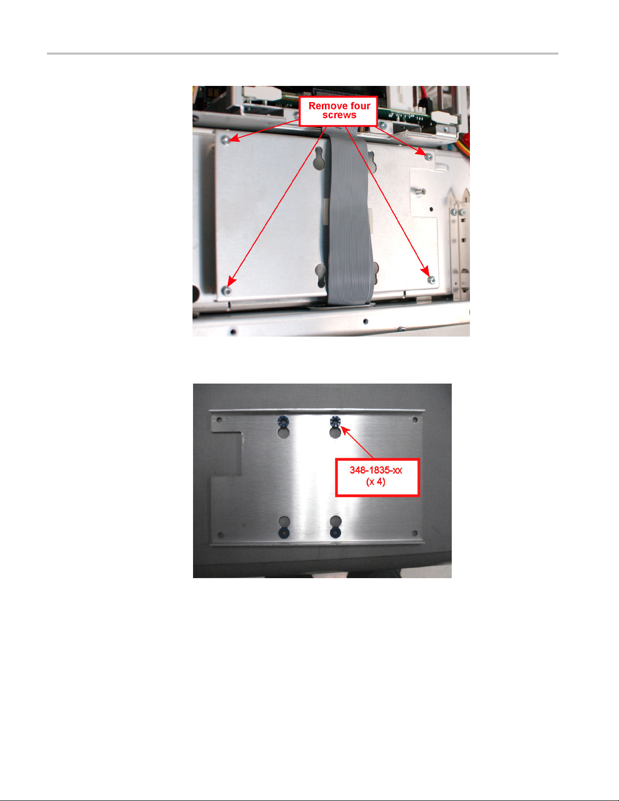
2. Remove the four screws at the corners of the hard disk drive mounting plate
that secure the mounting plate to the instrument.
3. Lift the hard disk drive mounting plate out of the instrument. Disconnect the
SATA cable from the hard disk drive.
4. Remove the four screws that secure the hard disk drive to the mounting plate.
RSA5100A Series Options 56, 57, and 59 Upgrades 9
Page 14

Installing New Drive Options
5. Place the remov
protected location for possible future use or discard the drive.
NOTE. If you discard or recycle the removed drive, be sure to follow your
organization’s security protocols to ensure the destruction of sensitive data.
6. Reinstall the hard disk drive mounting plate in the chassis.
ed hard drive in anti-static packaging and store it in a
Installing New Drive Options
This sections describes how to install your new drive options.
Installing Option 56: Removable Hard Disk Drive
To perform the following procedure you must have already removed Option 57
or 59 from your instrument. (See page 6, Removing a DVD Drive and Internal
Hard Drive (Option 57 or Option 59).)
1. Attach the removable hard drive to the removable hard disk drive bracket
(part number 407-5473-XX) with four screws (part number 211-1081-XX)
using a torque driver with a T1 tip. Tighten the screws to 4.0 in-lbs.
2. Attach the removable hard drive label to the removable hard drive bracket.
Start by centering one end of the label and making it flush with the b racket.
Make sure the label is correctly oriented with the bottom of the label aligned
with the bottom of the bracket.
3. Slide the removable hard disk drive assembly into the drive opening and
secure the hard drive with the two thumbscrews.
10 RSA5100A Series Options 56, 57, and 59 Upgrades
Page 15
Installing New Drive Options
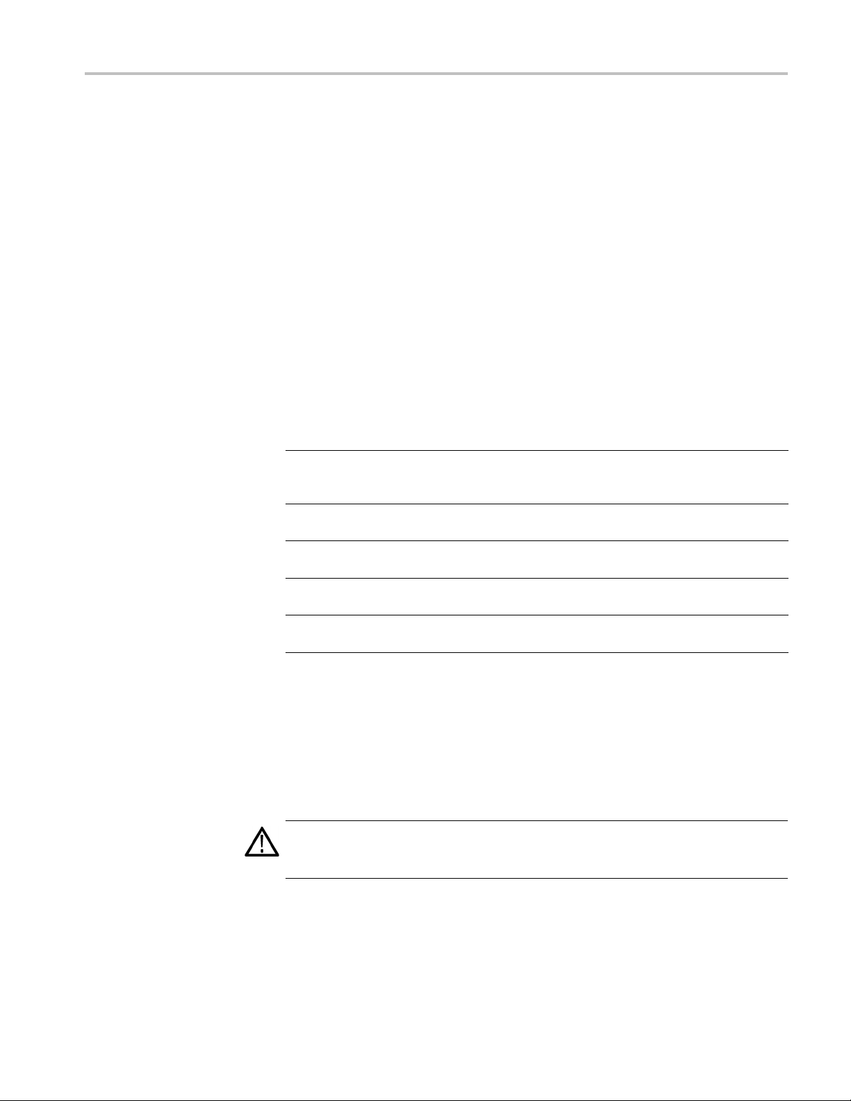
4. Connect the SAT
removable hard drive.
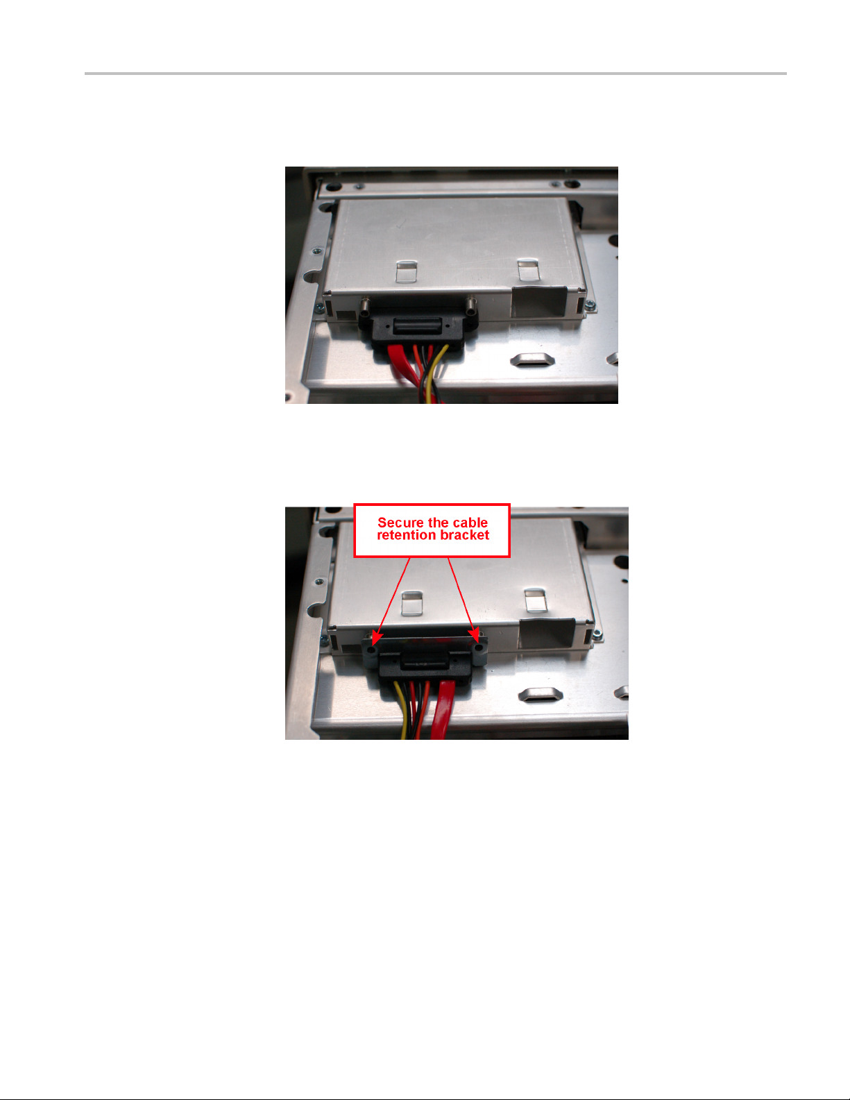
5. Slide the SATA combo cable retention bracket (part number 407–5337–00)
over the
211-1050-XX) using a torque driver with a T15 tip. Tighten the screws
to 4.0 in-lbs.
cable and secure the retention bracket with two screws (part number
A and power cable connector to the connector on the
6. Reinstall the top internal cover:
a. Position the top internal cover on the instrument, so that the protrusions in
the cover match up with the slots in the chassis.
b. Reinstall the 18 T15 to secure the cover to the chassis. Tighten these
screws to 8.0 in/lb.
RSA5100A Series Options 56, 57, and 59 Upgrades 11
Page 16

Installing New Drive Options
7. Reinstall the t
a. Place the instrument on its rear feet, so the front panel is facing up and
the top is towa
b. Place the top cover over the top of the instrument and slide it toward
the front pa
on the rear panel on all three sides.
c. Reinstall t
the top cover to the instrument, near the front edge of the top cover (next
to the folding handles).
d. Align the four screw holes on each side in the top and bottom covers with
the holes in the chassis, and install eight T15 screws, four on each side.
Tighten these screws to 8.0 in/lb.
e. Position the plastic carrying handle and its bracket on the right side of
the instrument, and install the two T15 screws that secure it in place.
Tighten these screws to 8.0 in/lb.
8. Remove the Windows Certificate of Authenticity from the rear panel. Replace
it with the Certificate of Authenticity provided in this kit.
9. Reinstall the power cord and power on the instrument.
op and bottom cosmetic covers and carrying handle:
rd you.
nel. Make sure that the top cover wraps around the flanges
he four 5/32” hex head screws (two on each side) that secure
This completes the upgrade from to Option 56. If you need to restore the operating
system on your instrument, use the operating system restore DVD (Tektronix
part number 020-3016-XX) that shipped with this upgrade kit. Do not use the
operating system restore disk that originally shipped with your instrument or any
rating system restore disks you might have created.
ope
Installing Option 57: DVD-R/W Drive and Internal Hard Drive
perform the following procedure you must have already removed Option 56
To
or 59 from your instrument. (See page 5, Removing a Removable Hard Disk
Drive (Option 56).)
DVD-R/W Drive. To install the DVD-R/W drive:
1. Slide the DVD drive (part number 119-7678-XX) into the DVD bracket (part
number 407-5476-XX) with the front of the DVD drive aligned with the tabs
on the DVD bracket.
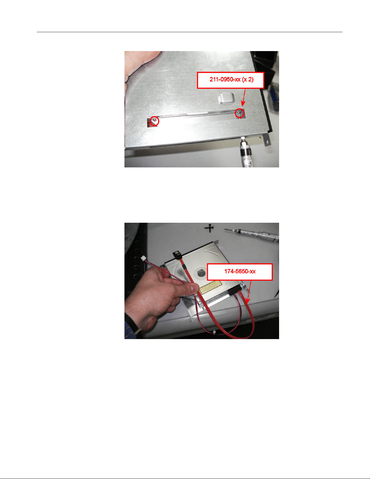
2. Turn the assembly on its side and secure the DVD drive to the DVD bracket
with 2 screws (part number 211-0950-XX), using a T0 tip. Tighten these
screws to 0.6 in/lb.
12 RSA5100A Series Options 56, 57, and 59 Upgrades
Page 17
Installing New Drive Options
3. Turn the assembly on to the opposite side and secure the DVD drive to the
DVD bracket using two screws (part number 211-0950-XX), using a T0 tip.
Tighten
these screws to 0.6 in/lb.
4. Attach the DVD cable (part number 174-5650-XX) to the rear of the DVD
drive.
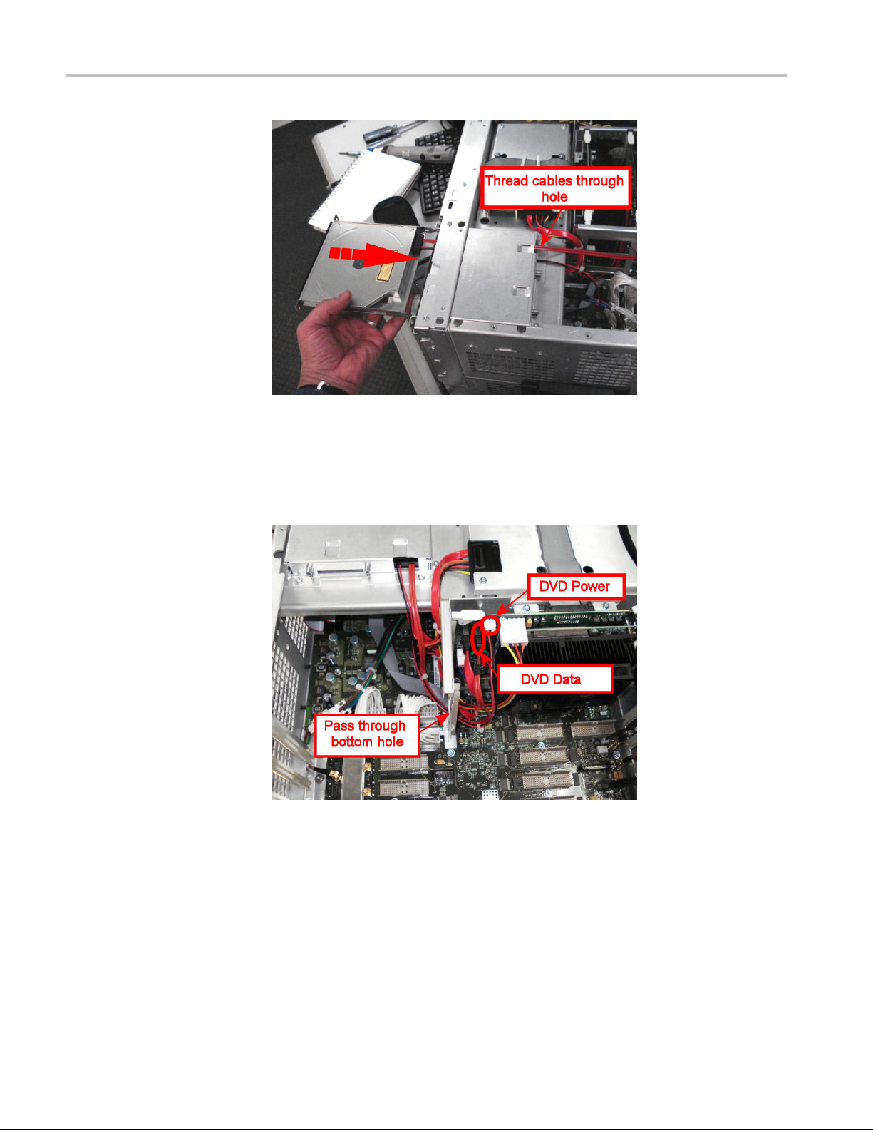
5. Holding the DVD assembly in front of the instrument, thread the DVD cables
through the opening in the front panel and back through the hole in the back of
the of the bracket. Slide the DVD assembly into the opening in the front panel.
RSA5100A Series Options 56, 57, and 59 Upgrades 13
Page 18
Installing New Drive Options
6. Mount the DVD cover (part number 200-5143-XX) to the front of the
instrument using two screws (part number 211-0690-XX) using a torque
driver w
ith a T-15 tip. Tighten these screws to 10 in/lb.
7. Thread the DVD cables through the bottom hole in the chasis bracket and
connect
8. Secure the DVD and HDD cables to the chassis bracket with one zip tie (part
number 343–0549–XX) as shown.
them to the PC carrier board as shown.
14 RSA5100A Series Options 56, 57, and 59 Upgrades
Page 19

Installing New Drive Options
Install Internal Hard Drive. To install the internal hard drive:
9. Disconne
the front of the instrument.
ct the video cables from the PC carrier board and fold them over
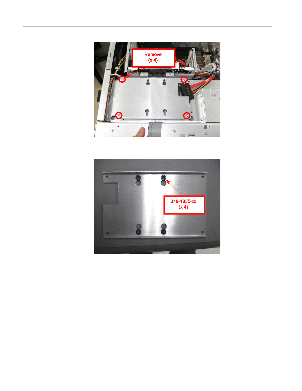
10. RemovethefourscrewsthatsecuretheHDDbrackettothechassisand
remove the bracket.
RSA5100A Series Options 56, 57, and 59 Upgrades 15
Page 20
Installing New Drive Options
11. Install four grommets (part number 348-1835-XX) on the HDD bracket as
shown.
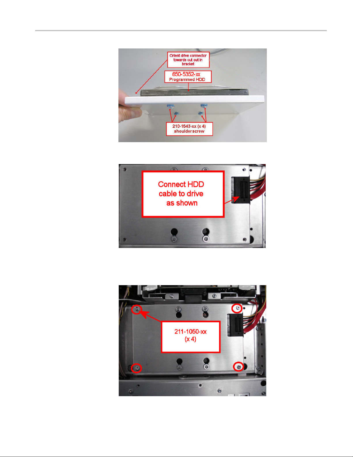
12. Place the drive assembly (part number 650-5352–XX) onto the HDD bracket
with the connector appears in the cutout in the HDD bracket. Secure the drive
assembly to the HDD bracket with four screws (part number 210-1543-XX)
ing a torque drive with a P1 tip. Tighten the screws to 4.0 in-lbs.
us
16 RSA5100A Series Options 56, 57, and 59 Upgrades
Page 21

Installing New Drive Options
13. Connect th
14. Place the drive assembly and HDD bracket on the chassis as shown. Secure
the HDD bracket to the chassis with four screws (part number 211-1050-XX)
using a torque driver with a T15 tip. Tighten these screws to 10 in/lb.
e HDD SATA cable to the drive assembly.
RSA5100A Series Options 56, 57, and 59 Upgrades 17
Page 22

Installing New Drive Options
15. Reconnect the s
16. Reconnect the larger video cable to the PC Carrier board.
17. Reinstall the top internal cover:
a. Position the top internal cover on the instrument, so that the protrusions in
the cover match up with the slots in the chassis.
maller video cable to the PC Carrier board.
b. Reinstall the 18 T15 to secure the cover to the chassis. Tighten these
screws to 8.0 in/lb.
18. Reinstall the top and bottom cosmetic covers and carrying handle:
a. Place the instrument on its rear feet, so the front panel is facing up and
the top is toward you.
b. Place the top cover over the top of the instrument and slide it toward
the front panel. Make sure that the top cover wraps around the flanges
on the rear panel on all three sides.
c. Reinstall the four 5/32” hex head screws (two on each side) that secure
the top cover to the instrument, near the front edge of the top cover (next
to the folding handles).
d. Align the four screw holes on each side in the top and bottom covers with
the holes in the chassis, and install eight T15 screws, four on each side.
Tighten these screws to 8.0 in/lb.
e. Position the plastic carrying handle and its bracket on the right side of
the instrument, and install the two T15 screws that secure it in place.
Tighten these screws to 8.0 in/lb.
19. Remove the Windows Certificate of A
it with the Certificate of Authenticity provided in this kit.
uthenticity from the rear panel. Replace
20. Reinstall the power cord and power on the instrument.
18 RSA5100A Series Options 56, 57, and 59 Upgrades
Page 23

Installing New Drive Options
This completes
operating system on your instrument, use the operating system restore DVD
(Tektronix part number 020-3016-XX) that shipped with this upgrade kit. Do not
use the operating system restore disk that originally shipped with your instrument.
the upgrade from to Option 57. If you ever need to restore the
Installing Option 59: Internal Hard Drive
To perform the following procedure you must have already removed Option 56
from your instrument. (See page 5, Removing a Removable Hard Disk Drive
(Option 56).)
To install the internal hard drive:
1. Disconnect the video cables from the PC Carrier board and fold them over
the front of the instrument.
2. RemovethefourscrewsthatsecuretheHDDbrackettothechassisand
ove the bracket.
rem
RSA5100A Series Options 56, 57, and 59 Upgrades 19
Page 24
Installing New Drive Options
3. Install four grommets (part number 348-1835-XX) on the HDD bracket as
shown.
4. Plac
20 RSA5100A Series Options 56, 57, and 59 Upgrades
e the drive assembly (part number 650-5352–XX) onto the HDD bracket
with the connector appears in the cutout in the HDD bracket. Secure the drive
assembly to the HDD bracket with four screws (part number 210-1543-XX)
using a torque drive with a P1 tip. Tighten the screws to 4.0 in-lbs.
Page 25
Installing New Drive Options
5. Connect th
6. Place the drive assembly and HDD bracket on the chassis as shown. Secure
the HDD bracket to the chassis with four screws (part number 211-1050-XX)
using a torque driver with a T15 tip. Tighten these screws to 10 in/lb.
e HDD SATA cable to the drive assembly.
RSA5100A Series Options 56, 57, and 59 Upgrades 21
Page 26

Installing New Drive Options
7. Reconnect the s
8. Reconnect the larger video cable to the PC Carrier board.
9. Reinstall the top internal cover:
a. Position the top internal cover on the instrument, so that the protrusions in
the cover match up with the slots in the chassis.
b. Reinstall the 18 T15 to secure the cover to the chassis. Tighten these
screws to 8.0 in/lb.
10. Reinstall the top and bottom cosmetic covers and carrying handle:
a. Place the instrument on its rear feet, so the front panel is facing up and
the top is toward you.
b. Place the top cover over the top of the instrument and slide it toward
the front panel. Make sure that the top cover wraps around the flanges
on the rear panel on all three sides.
c. Reinstall the four 5/32” hex head screws (two on each side) that secure
the top cover to the instrument, near the front edge of the top cover (next
to the folding handles).
d. Align the four screw holes on each side in the top and bottom covers with
the holes in the chassis, and install eight T15 screws, four on each side.
ten these screws to 8.0 in/lb.
Tigh
maller video cable to the PC Carrier board.
e. Position the plastic carrying handle and its bracket on the right side of
instrument, and install the two T15 screws that secure it in place.
the
Tighten these screws to 8.0 in/lb.
11.Re
12.Re
This completes the upgrade from to Option 59. If you need to restore the operating
s
part number 020-3016-XX) that shipped with this upgrade kit. Do not use the
operating system restore disk that originally shipped with your instrument.
move the Windows Certificate of Authenticity from the rear panel. Replace
it with the Certificate of Authenticity provided in this kit.
install the power cord and power on the instrument.
ystem on your instrument, use the operating system restore DVD (Tektronix
22 RSA5100A Series Options 56, 57, and 59 Upgrades
 Loading...