

Page 1

xx
RSA5BUP (Options PFR, 50, PFR50)
RSA5100B Series Real-Time Signal Analyzers
ZZZ
Preamp and Precision Frequency Reference Upgrades
Instructions
www.tektronix.com
P075105901*
*
075-1059-01
Page 2

Copyright © Tektronix. All rights reserved. Licensed software products are owned by Tektronix or its subsidiaries
or suppliers, and are protected by national copyright laws and international treaty provisions.
Tektronix products are covered by U.S. and foreign patents, issued and pending. Information in this publication
supersedes that in all previously published material. Specifications and price change privileges reserved.
TEKTRONIX and TEK are registered trademarks of Tektronix, Inc.
Page 3

Service safety summary
Only qualified personnel should perform service procedures. Read this Service
Safety Summary and the General Safety Summary located in the RSA5100B
Series Real-
procedures.
Do not service alone. Do not perform internal service or adjustments of this
product unless another person capable of rendering first aid and resuscitation is
present.
Disconnect power. To avoid electric shock, switch off the instrument power, then
disconnect the power cord from the mains power.
Use care when servicing with power on. Dangerous voltages or currents may exist
in this product. Disconnect power, remove battery (if applicable), and disconnect
test le
To avoid electric shock, do not touch exposed connections.
Time Signal Analyzers Service Manual before performing any service
ads before removing protective panels, soldering, or replacing components.
Kit description
Products
This kit describes the installation of the following upgrade options:
on PFR: Precision Frequency Reference for the RSA5100B Series
Opti
Option 50: Internal Preamp for the RSA5103B and RSA5106B
Option PFR50: Internal Preamp with the Precision Frequency Reference
for the RSA5103B and RSA5106B
RSA5103B. All serial numbers
RSA5106B. All serial numbers
RSA5115B. All serial numbers
RSA5126B. All serial numbers
RSA5100B Series Options 50, PFR, PFR50 Upgrades 1
Page 4

Kit description
Option 50 kit p
arts list
Option PFR kit parts list
Quantity Part number Description
1 ea 071-2191-xx
1 ea 075-1059-xx
1 ea 850-0296-xx
1ea
1ea
Quanti
1 ea 071-2191-xx
N/A LABEL, MANUFACTURED; OPTION KEY UPGRADE
N/A LABEL, MANUFACTURED; PRODUCT LABEL, SAFETY
ty
Part nu
mber
MANUAL, TECH; SVCPT-UPG; TEKTRONIX
SUPPLEMENTAL INFORMATION SHEET FOR THE
PEOPLES REPUBLIC OF CHINA; CHINA ROHS
INSTRUCTIONS, UPGRADE: RSA5BUP OPTIONS PFR,
50, PFR50
MFG ASSY; RSA5BUP 50
LABEL 2.100 X 2.700, SAFETY CONTROLLED
CONTROLLED
ption
Descri
MANUAL, TECH; SVCPT-UPG; TEKTRONIX
SUPPLE
PEOPLES REPUBLIC OF CHINA; CHINA ROHS
MENTAL INFO RM ATION SHEET F OR THE
tion PFR50 kit parts list
Op
1 ea 075-1059-xx
1 ea 863-0956-xx
1ea
1ea
Quantity Part number Description
1 ea 071-2191-xx
1 ea 075-1059-xx
1 ea 850-0296-xx
1 ea 863-0956-xx
N/A LABEL, MANUFACTURED; OPTION KEY UPGRADE
N/A LABEL, MANUFACTURED; PRODUCT LABEL, SAFETY
UCTIONS, UPGRADE: RSA5BUP OPTIONS PFR,
INSTR
50, PFR50
D; RSA5BUP PFR
CKT B
EL 2.100 X 2.700, SAFETY CONTROLLED
LAB
NTROLLED
CO
MANUAL, TECH; SVCPT-UPG; TEKTRONIX
SUPPLEMENTAL INFORMATION SHEET FOR THE
PEOPLES REPUBLIC OF CHINA; CHINA ROHS
INSTRUCTIONS, UPGRADE: RSA5BUP OPTIONS PFR,
50, PFR50
MFG ASSY; RSA5BUP 50
CKT BD; RSA5BUP PFR
2 RSA5100B Series Options 50, PFR, PFR50 Upgrades
Page 5

Quantity Part num ber Description
Installation instructions
1ea
1ea
Installation instructions
This section contains all procedures needed to install the required components.
Minimum t
ool and equipment list
The following tools are required to for installation of this kit. All tools are
standard tools that are readily available.
Item Name Description
1
2 No. 2 Phillips or Pozidriv tip
3
4
5
Screwdriver handle (magnetic)
T-15 TORX tip TORX driver tip for T-15 size screw
T-20 TORX tip TORX driver tip for T-20 size screw
5/16” hex wrench Open end wrench to remove and install
N/A LABEL, MANUFACTURED; OPTION KEY UPGRADE
LABEL 2.100 X 2.700, SAFETY CONTROLLED
N/A LABEL, MANUFACTURED; PRODUCT LABEL, SAFETY
CONTROLLED
Torque driver. Accepts 14 inch
hex-head driver tips
Phillips or Pozidriv-driver tip for number
2 size screw heads
heads
heads
semi-rigid cables
These instructions are for qualified service personnel who are familiar
with servicing the product. If you need further details for disassembling or
assembling the product, refer to the RSA5100B Series Real-Time Signal
re
Analyzers Service Manual, Tektronix part number 077-0903-XX.
RSA5100B Series Options 50, PFR, PFR50 Upgrades 3
Page 6

Installation instructions
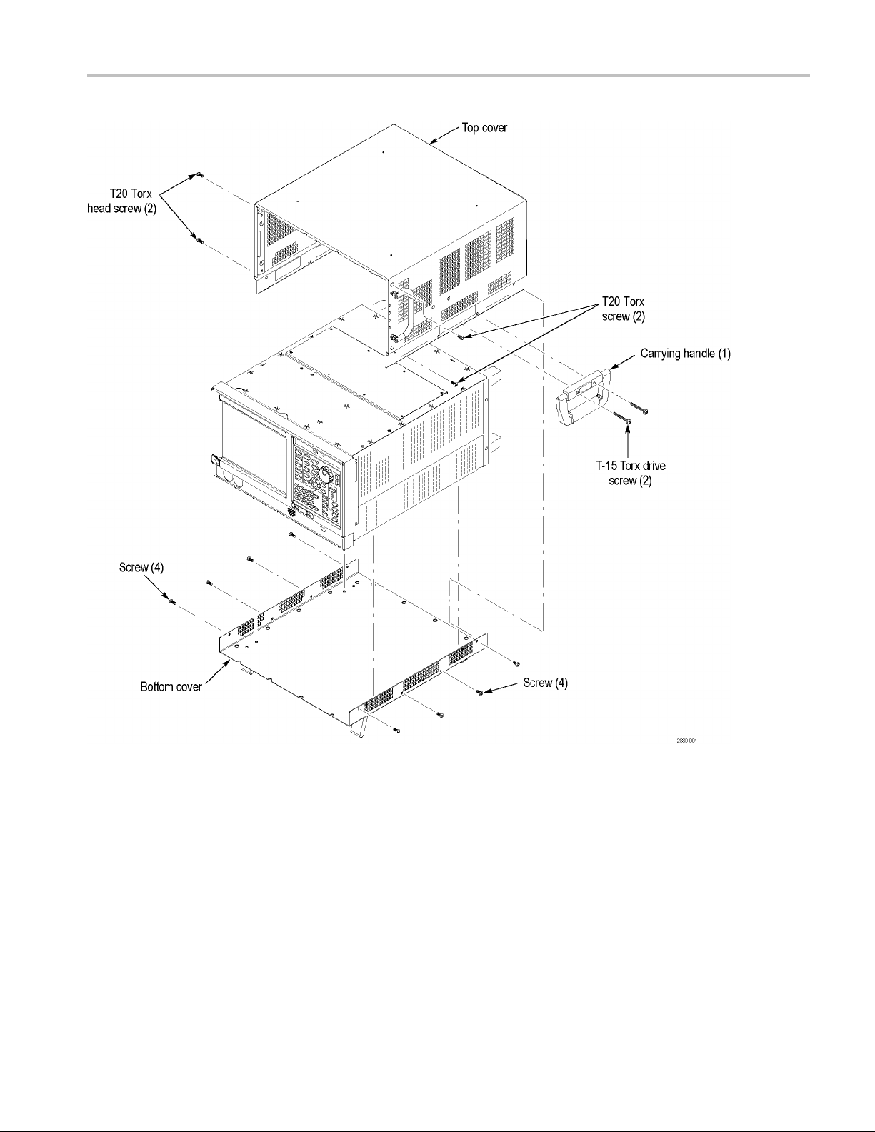
Remove covers
NOTE. Right-side or left-side references in these instructions assume you are
viewing the in
WARNING. To avoid electric shock, switch off the instrument power, then
disconnect
injury or death.
strument from the front panel.
the power cord from the mains power. Failure to do so can cause
1. Remove the
2. If it is installed, pull the front cover off the instrument.
3. Remove the two T-15 Torx-head screws that attach the plastic carrying handle
to the side of the instrument. (It is not necessary to remove the black metal
handles
4. Remove four T15 Torx-head screws along each side that attach the top and
bottom
the top cover (next to the folding handles).
5. Remov
straight back about 1 inch. Pull out on the sides of the top cover, flexing the
sides slightly to clear the instrument chassis, and pull the top cover away
from the instrument.
6. Turn the instrument over so it is resting on its top.
7. Remove the three T-15 Torx-head screws that attach the lower trim panel to
the chassis, and lift the lower trim panel from the instrument.
8. Remove the 18 T15 Torx-head screws that attach the internal bottom cover to
the chassis, and then lift the internal bottom cover away.
power cord.
.) (See Figure 1.)
covers to the instrument, and two T20 screws ne ar the front edge of
e the top and bottom covers. Remove the top cover by pulling it
4 RSA5100B Series Options 50, PFR, PFR50 Upgrades
Page 7
Installation instructions
Figure 1: Remove covers
RSA5100B Series Options 50, PFR, PFR50 Upgrades 5
Page 8

Installation instructions
Install Pream
p option board (Options 50 and PFR50)
These options only apply to the RSA5103B and RSA5106B instruments.
1. Disconnect the semi-rigid cable connecting the ATT OUT connector to the
1ST CONV IN connector:
a. Loosen t
not pull the cable connector away from the ATT OUT connector.
he semi-rigid cable connecting to the ATT OUT connector. Do
b. Loosen
completely. Rotate the semi-rigid cable upward. Now remove the
semi-rigid cable from the ATT OUT connector.
the semi–rigid cable connecting to t he 1ST CONV IN connector
6 RSA5100B Series Options 50, PFR, PFR50 Upgrades
Page 9
Installation instructions
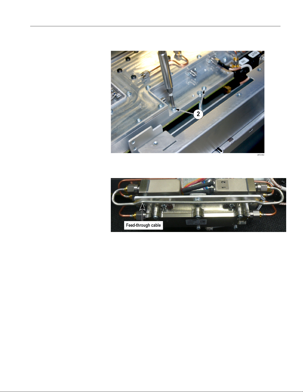
2. Remove the two s
3. Remove semi-rigid feed-through cable from preamp assembly before
installing assembly. This allows access to the connectors below if needed.
crews from the chassis and set aside for later reuse.
a. Loosen one side (either side is okay) of the semi-rigid feed-through c able
so the nut turns easily.
b. Loosen the nut on the opposite end of the semi-rigid feed-through cable.
c. Pull on one end of the semi-rigid feed-through cable straight out from
the relay until the nut on the semi-rigid feed-through cable clears the
connector on the relay.
d. Loosen the opposite end of the semi-rigid feed-through cable and remove
the semi-rigid feed-through cable from the preamp assembly.
RSA5100B Series Options 50, PFR, PFR50 Upgrades 7
Page 10

Installation instructions
4. Set the preamp a
with the ATT OUT and 1ST CONV IN connectors.
5. Use the two screws, previously set aside, to attach the preamp assembly to
the 1st Converter. Do not tighten the screws yet.
6. Screw the nuts on the end of the semi-rigid cables on to the ATT OUT
connector and 1ST CONV IN connector. Finger tighten the nut. If you
encounter any difficulty securing the nut to the connector, loosen the nut from
the connector and try connecting it again. It is critical that the alignment
between the semi-rigid cable and the connector be kept as straight as possible
to avoi
d possible calibration failure.
ssembly on the 1st Converter. Align the semi-rigid cables
7. Tighten the screws securing the preamp assembly to the 1st Converter.
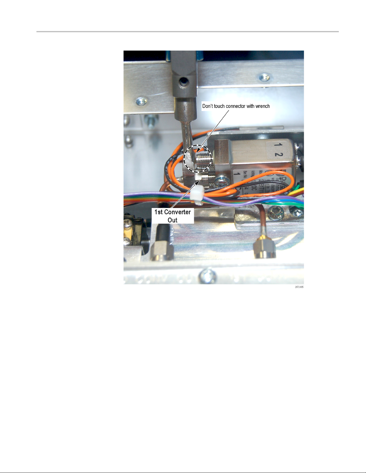
8. Torque the semi-rigid cable nut on the relay for the 1st Converter Out
connection to 10 in-lbs. Do not over-torque the nut. Stop tightening the nut as
as the torque wrench first “breaks”.
soon
CAUTION. To avoid damaging the relay connector on the preamp assembly, be
careful not to touch the connector on the relay with the torque wrench while
tightening the nuts.
8 RSA5100B Series Options 50, PFR, PFR50 Upgrades
Page 11
Installation instructions
9. Torque the nut on the connector below the relay for the ATT OUT connection
to 10 in-lbs. Do not over-torque the nut. Stop tightening the nut as soon as the
ue wrench first “breaks”.
torq
RSA5100B Series Options 50, PFR, PFR50 Upgrades 9
Page 12

Installation instructions
10. Torque the semi-rigid cable connections to the 1ST CONV IN and ATT OUT
connectors on the instrument to 10 in-lbs. Do not over-torque the nuts.
11. Reattach the semi-rigid feed-through cable on one end of the preamp. Finger
tighten the nut about half way.
10 RSA5100B Series Options 50, PFR, PFR50 Upgrades
Page 13

Installation instructions
12. Pull on the othe
semi-rigid cable clears the connector on the relay (do not slide the nut over
the connector). Align the nut on the semi-rigid cable with the connector on
the relay and screw the nut on to the connector. Finger tighten the nut. The
tension in the semi-rigid cable will relax.
13. Holding the semi-rigid feed-through cable level with your fingers, torque the
nuts on both ends of the semi-rigid cable to 10 in-lbs.
r end of the semi-rigid cable so that the nut on the end of the
RSA5100B Series Options 50, PFR, PFR50 Upgrades 11
Page 14

Installation instructions
14. Feed the relay c
following figure.
15. Insert the two wire cable into t he power socket. Push the cable fully into the
socket a
nd listen for a click sound.
ontrol cable under the semi-rigid cable as shown in the
16. Insert the ribbon cable in the connector. Push the cable fully into the socket
and listen for a click sound.
17. After inserting the cables into the sockets, pull up on the cables to be sure
they do not disconnect.
12 RSA5100B Series Options 50, PFR, PFR50 Upgrades
Page 15

Installation instructions
18. Inspect the rib
find any pins visible above the plastic connector body, remove the connector,
reinsert the pins into the connector body and reinsert the cable connector. Pull
on the ribbon connector to be sure it is fully seated.
bon cables carefully for pins that are not fully inserted. If you
RSA5100B Series Options 50, PFR, PFR50 Upgrades 13
Page 16
Installation instructions
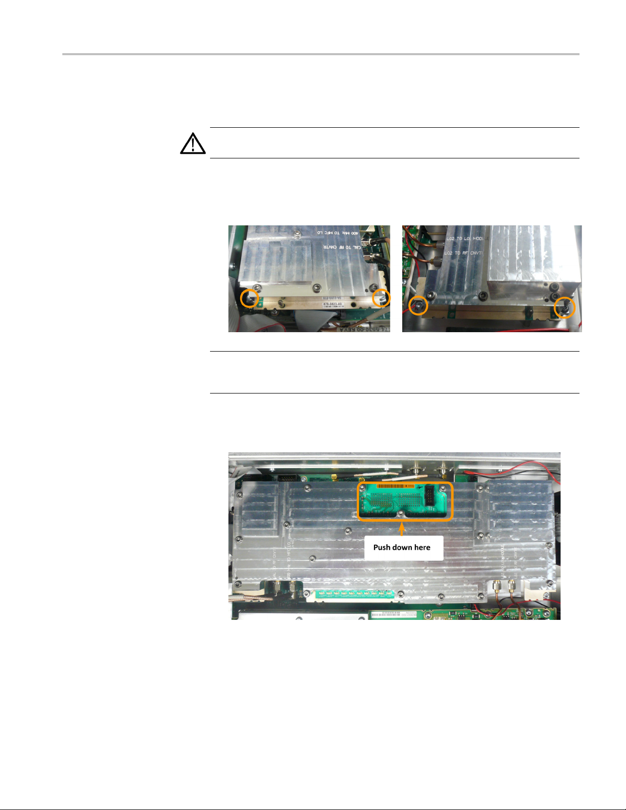
Install Preci
sion Frequency Reference option board (Options PFR and PFR50)
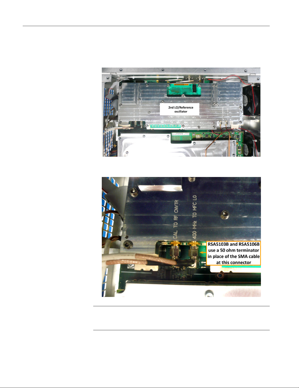
1. Locate the 2nd LO/Reference oscillator board. The board is located near the
rear of the instrument.
2. Disconnect the SMA cables from the CAL TO RF CNVTR and 400 MHz TO
MFC LO connectors.
NOTE. RSA5103B and RSA5106B instruments do not have an SMA cable
connected to the 400 MHz TO MFC LO connector.
In place is a 50 Ω terminator. Remove and save the terminator for reinstallation.
14 RSA5100B Series Options 50, PFR, PFR50 Upgrades
Page 17
Installation instructions
3. Disconnect the
LO2 TO RF CNVTR connectors.
CAUTION. Do not bend the semi-ridged cables.
4. Remove the four T15 T
secure the 2nd LO/Reference oscillator board to the chassis and remove the
board.
NOTE. Make sure n
the option board contained in this kit. With the shields in place, they are very
difficult to distinguish between the two.
semi-ridged cables from the LO2 TO LO1 MODULE and
orx-head screws (at each corner of the board) that
ot to mix the standard board removed from the instrument with
5. Install the PFR option board into the same location. Press down on the board
to ensure the connector on the underside of the board is fully seated.
6. Secure the board using the four T15 Torx-head screws previous removed.
Torque the screws to 10 in-lbs.
RSA5100B Series Options 50, PFR, PFR50 Upgrades 15
Page 18

Installation instructions
Reinstal
7. Reconnect the s
TO RF CNVTR connectors. Torque the connections to 10 in-lbs. Do not
over-torque the nuts.
8. Reconnect the SMA cables from the CAL TO RF CNVTR and 400 MHz TO
MFC LO connectors. Torque the connections to 10 in-lbs. Do not over-torque
the nuts.
NOTE. RSA5103B and RSA5106B instruments, place the 50 Ω terminator on
the 400 MHz TO MFC LO connector.
emi-ridged cables to the LO2 TO LO1 M ODULE and LO2
l bottom shield and cosmetic covers
Reinstall the top and bottom cosmetic covers:
1. Place the bottom shield on the instrument, aligning the two protrusions on the
shield with the two slots in the chassis.
2. Replace the 18 T-15 Torx-head screws that attach the bottom shield to the
instrument. Torque these screws to 8 in-lbs.
3. Place the instrument on its rear feet, so the front panel is facing up and the
top is toward you.
4. Place the top cover over the top of the instrument and slide it toward the
front panel. Make sure that the top cover wraps around the flanges on the
rear panel on all three sides.
5. ReinstallthefourT20Torxheadscrews(twooneachside)nearthefront
edge of the top cover (next to the folding handles) that attach the top cover
he instrument.
to t
6. Rotate the instrument so the bottom faces you.
7. Place the bottom cover on the instrument, with the flip feet toward the front.
8. Align the four screw holes on each side in the top and bottom covers with the
holes in the chassis, and install eight T15 screws, four on each side. Torque
these screws to 8.0 in-lb.
9. Position the plastic carrying handle and its bracket on the right side of the
instrument, and install the two T15 screws that attach it in place. Torque
these screws to 8.0 in-lb.
16 RSA5100B Series Options 50, PFR, PFR50 Upgrades
Page 19
Install option key
Installation instructions
To activate your new option, you must enter a new option key.
1. Power on the instrument.
NOTE. When the application launches, it will display an error message indicating
that the current option key does not support the new option hardware. Click
OK to clear the error message.
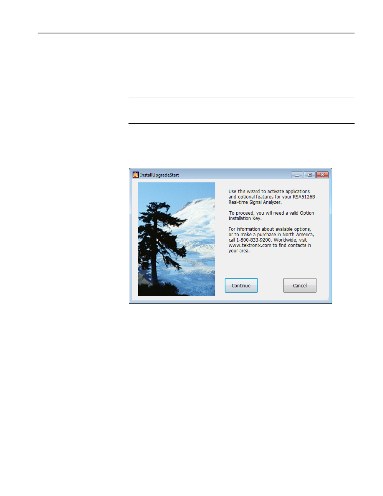
2. Select Tools > Install Upgrades... to start the upgrade installation process.
3. Click Continue from the Install Upgrades introduction screen.
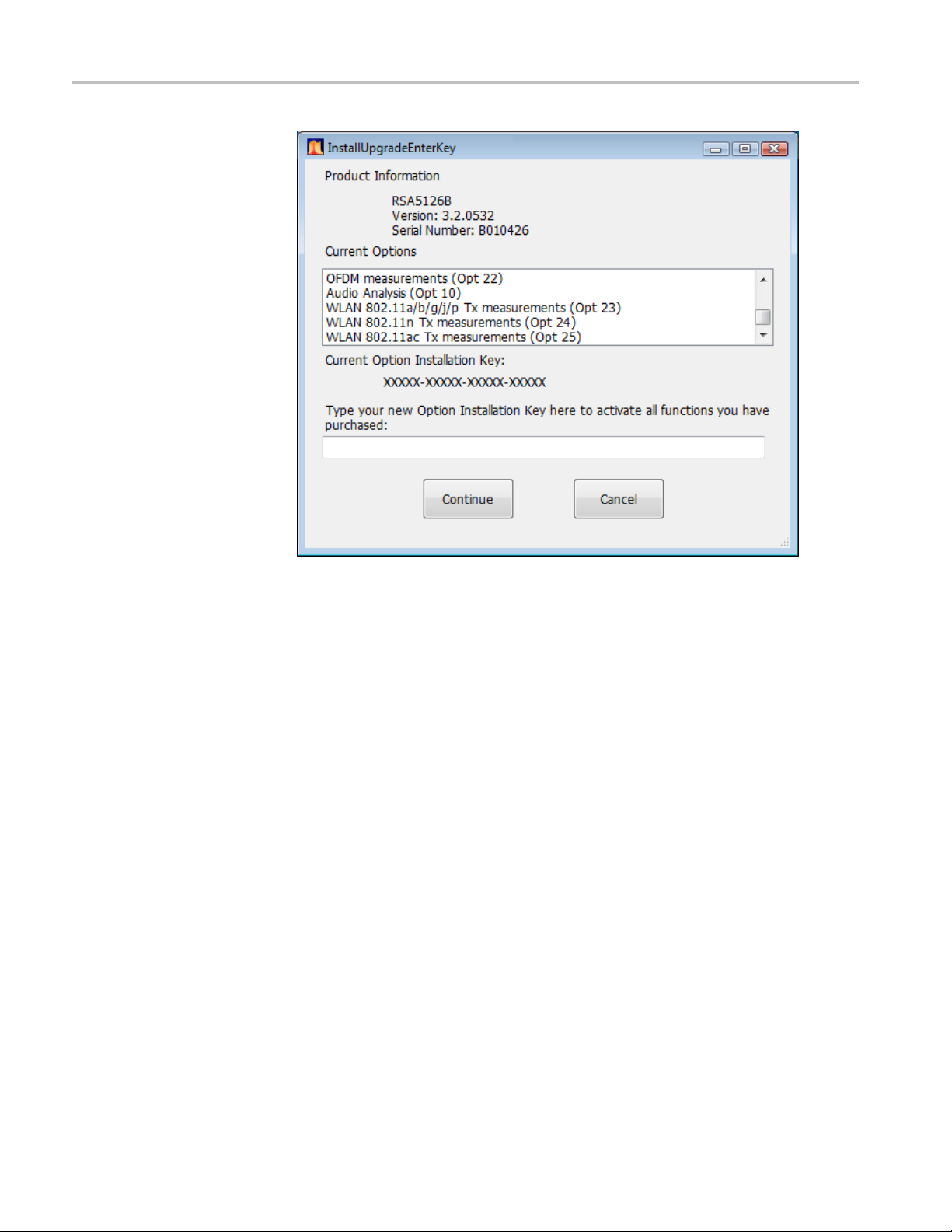
4. Enter the option key provided by Tektronix, and follow the on-screen
tructions to install the option.
ins
RSA5100B Series Options 50, PFR, PFR50 Upgrades 17
Page 20
Installation instructions
Attach labels
Attach the option key label
Attach the product/option
labe
5. Power off the instrument, then power back on.
6. In the Help menu, select About Tektronix Real-Time Analyzer.
7. Verify
Pleas
Place the new option key label over the existing label on the rear panel.
Place the new product label over the existing label on the rear panel.
the new option is listed.
e attach all labels provided in this kit on the instrument’s rear panel.
l
18 RSA5100B Series Options 50, PFR, PFR50 Upgrades
Page 21

Recalibrate the instrument
The installation of the options in this kit requires that the instrument be
recalibrated.
NOTE. Failure to perform a system calibration after installing this upgrade will
result in a “Data from Uncalibrated Instrument” warning on the application
display.
Verify instrument software version
Tektronix recommends to update to the latest available application software for
your instrument.
1. Select Help > About to check the software version.
2. Use your Web browser to go to: www.tektronix.com/software.
Verify instrument software version
3. Search
4. If the installed software is older than that available, download the software.
5. Follow the instructions on the Web page to install the software.
■ End of Document ■
for your instrument’s model number and follow the link to the software.
RSA5100B Series Options 50, PFR, PFR50 Upgrades 19
 Loading...