

Page 1

xx
RSA56KR Rackmount for
ZZZ
RSA6100A Series and RSA5100A Series Analyzers
Instructions
www.tektronix.com
P075102300*
*
075-1023-00
Page 2

Copyright © Tektronix. All rights reserved. Licensed software products are owned by Tektronix or its subsidiaries
or suppliers, and are protected by national copyright laws and international treaty provisions.
Tektronix products are covered by U.S. and foreign patents, issued and pending. Information in this publication
supersedes that in all previously published material. Specifications and price change privileges reserved.
TEKTRONIX and TEK are registered trademarks of Tektronix, Inc.
Contacting Tektronix
Tektronix, Inc.
14150 SW Karl Braun Drive
P.O. B o x 5 0 0
Beaverto
USA
For product information, sales, service, and technical support:
n, OR 97077
In North America, call 1-800-833-9200.
Worl dwid e, vis it www.tektronix.com to find contacts in your area.
Page 3

Table of Contents
Service Safety Summary.......................................... ................................ ................. 1
Kit Description........................................... ................................ ........................... 2
Products ................................ ................................ ................................ ......... 2
Kit Parts Li
Warranted Characteristics..................................................................................... 3
Environmental Requirements................................................................................. 4
Clearance Requirements ....... ................................ .................................. ............. 5
Installation Instructions............................................................................................ 7
Minimum Tool and Equipment List ........ ................................ ................................. 7
Remove .... .................................. ................................ ................................ ... 8
Install......................... ................................ ................................ .................. 11
Rackmount the Rack-Adapted Instrument ................................................................. 14
st .............. ................................ ................................ ..................... 2
RSA56KR Rackmount Installation Instructions i
Page 4

Table of Contents
ii RSA56KR Rackmount Installation Instructions
Page 5

Service Safety Summary
Only qualified personnel should perform service procedures. Read this Service
Safety Summary and the General Safety Summary located in the Service m anual
for your inst
manual part number: 077-0522-XX) before performing any service procedures.
Do Not Service Alone. Do not perform internal service or adjustments of this
product unless another person capable of rendering first aid and resuscitation is
present.
To prevent the instrument and rack from falling onto the operator, two or more
installers should install the instrument into the rack cabinet. After completing the
install
cabinet will not tip forward while the instrument is in the extended position.
Disconnect Power. To avoid electric shock, switch off the instrument power, then
disconnect the power cord from the mains power.
rument (RSA6100A manual part number: 077-0250-XX; RSA5100A
ation procedure, the installers should verify that the instrument and rack
Use Ca
exist in this product. Disconnect power, remove battery (if applicable), and
disconnect test leads before removing protective panels, soldering, or replacing
components.
To avoid electric shock, do not touch exposed connections.
re When Servicing With Power On. Dangerousvoltagesorcurrentsmay
RSA56KR Rackmount Installation Instructions 1
Page 6

Kit Description
Kit Description
Products
Kit Parts List
This kit describes the installation of the RSA56KR Rackmount kit on your
RSA6100A Series or RSA5100A Series analyzer. The rackmount kit is a
collection o
f parts that, once installed, configures the instrument for mounting
into a standard 19-inch equipment rack.
RSA6100A Series. All instruments
RSA5100A Series. All instruments
Figure 3
on page 8 Quantit
–––
–––
3-1 1 ea 441-2665-XX
3-2 1 ea 351-0313-01
3–3 4 ea
3-3
3-3 14 e
3-3 4 ea
3-3 4 ea
3-3 8 ea
3-3 4 ea
3-3 9 ea
3-4 1 ea 351-0241-XX
3-4 1 ea
3-5 2 ea 367-0525-XX Handle: Bracket, aluminum, silver gray
y
1 ea 016-2040-XX
1 ea 075-10
7ea
a
Part num
NS Scre
NS
NS Screw, mach: 10-32, Truss head, 0.5
NS Screw, mach: M6 x 20 ovl head, Phillips
NS Screw, mach: M5 x 20 ovl head, Phillips
NS Screw, mach: 10-32 x 0.75 ovl head,
NS Screw, mach: 12-32 x 0.75 ovl head,
NS Washer: flat, nylon
NS
ber
23-XX
Descrip
Rackmou
consisting of the following:
Techni
Rackmount,RSA6100A Series,
RSA5100A Series
Bracket, rackmount (right and left)
Guide rack, consisting of: left and right
side
in l, Phillips
Nut
in l, phillips
P
Phillips
Slide, drawer, extenders: Sliders
Rack: Mounting screws, nut blocks
tion
nt Kit: RSA5000/6000 Series,
cal manual: Instructions,
w, mach: 10-32, pan head, 0.375
, locking washer: 10-32 assembly
hillips
2 RSA56KR Rackmount Installation Instructions
Page 7

Figure 3
on page 8 Quantity Part number Description
3-6 4 ea 212-0577-XX
NS — Not Saleable
Warranted Characteristics
Kit Description
Screw, mach: 10-32, Truss head, 0.625
in, Pozidriv
®
When the ins
trument is installed as instructed in this document, the rackmounted
instrument meets all warranted requirements listed in the instrument specification
except for those listed in Environmental Requirements.(See page 4, Environmental
Requirements.) Use of mounting methods other than those described in these
instructions can cause the instrument to not meet warranted requirements.
See the Specifications and Performance Verification Technical Reference for your
instrument for tables of the warranted characteristics.
Cooling air enters from the left side of the instrument. (See Figure 1.). You assume
the responsibility to provide adequate cool air to meet the ambient temperature
requirements listed in the Warranted Characteristics table. (See Table 1.).
RSA56KR Rackmount Installation Instructions 3
Page 8

Kit Description
Figure
Environmental Requirements
The following environmental characteristics supersede those listed in the user
or service manual for your instrument.
Table 1: Warranted characteristics
Characteristic Description
Temperature, Inside rack cabinet
Operating RSA6100A Series: +5° C to +50° C
Non-operating
1: Instrument cooling
When accessing
DVD
RSA5100A Series: +5° C to +40° C
+5° C to +40° C
–20° C to +60° C
4 RSA56KR Rackmount Installation Instructions
Page 9

Table 1: Warranted characteristics, (cont.)
Characteristic Description
Vibration
Operating 0.22 Grms. Profile = 0.00010 g2/Hz at 5 Hz to 350 Hz,
-3 dB/Octave slope from 350 Hz to 500 Hz, 0.00007 g
at 500 Hz, 3 Axes at 10 min/axis (Except when equipped
with optional Removable HDD (RSA6100A Series), or
when accessing DVD/CD)
RSA6100A Series: When equipped with Option 08,
Non-operating
Shock
Operating and
Non-operating
Removable Solid State HardDrive:0.27Grms.Profile =
0.00015 g
350 Hz to 500 Hz, 0.000105 g
10 min/axis
RSA6100A Series: 2.28 Grms. Profile = 0.0175 g2/Hz at 5
Hz to 100 Hz, -3 dB/Octave slope from 100 Hz to 200 Hz,
0.00875 g
from 350 Hz to 500 Hz, 0.00613 g
at 10 min/axis
RSA5100A Series: 2.28 Grms. Profile = 0.0175 g
Hz to 100 Hz, -3 dB/Octave slope from 100 Hz to 200 Hz,
0.00875 g
from 350 Hz to 500 Hz, 0.00613 g
at 10 min/axis
RSA6100A Series: 20 g, 11 ms, half sine, each axis, 3
drops each
RSA5100A Series: 15g, 11 ms, half sine, each axis, 3
drops each
2
/Hz at 5 Hz to 350 Hz, -3dB/Octave slope from
2
/Hz at 200 Hz to 350 Hz, -3 dB/Octave slope
2
/Hz at 200 Hz to 350 Hz, -3 dB/Octave slope
2
/Hz at 500 Hz, 3 Axes at
2
/Hz at 500 Hz, 3 Axes
2
/Hz at 500 Hz, 3 Axes
Kit Description
2
/Hz
2
/Hz at 5
Clearance Requirements
The rack in which the rack-adapted instrument is mounted must provide the
following clearance requirements:
A minimum of 266.7 mm (10.5 in) of vertical space.
A minimum width of 448 mm (17 5/8 in) between the left- and right-front
rails in the rack.
A minimum inside depth of at least 508 mm (20.5 in).
CAUTION. By adhering to these clearance requirements, the rack-adapted
instrument will be mounted with sufficient clearance for air circulation and
accommodation of the power cord and mounting hardware. Failure to provide
these clearances can result in overheating and will cause the instrument to not
operate properly and/or fail.
RSA56KR Rackmount Installation Instructions 5
Page 10
Kit Description
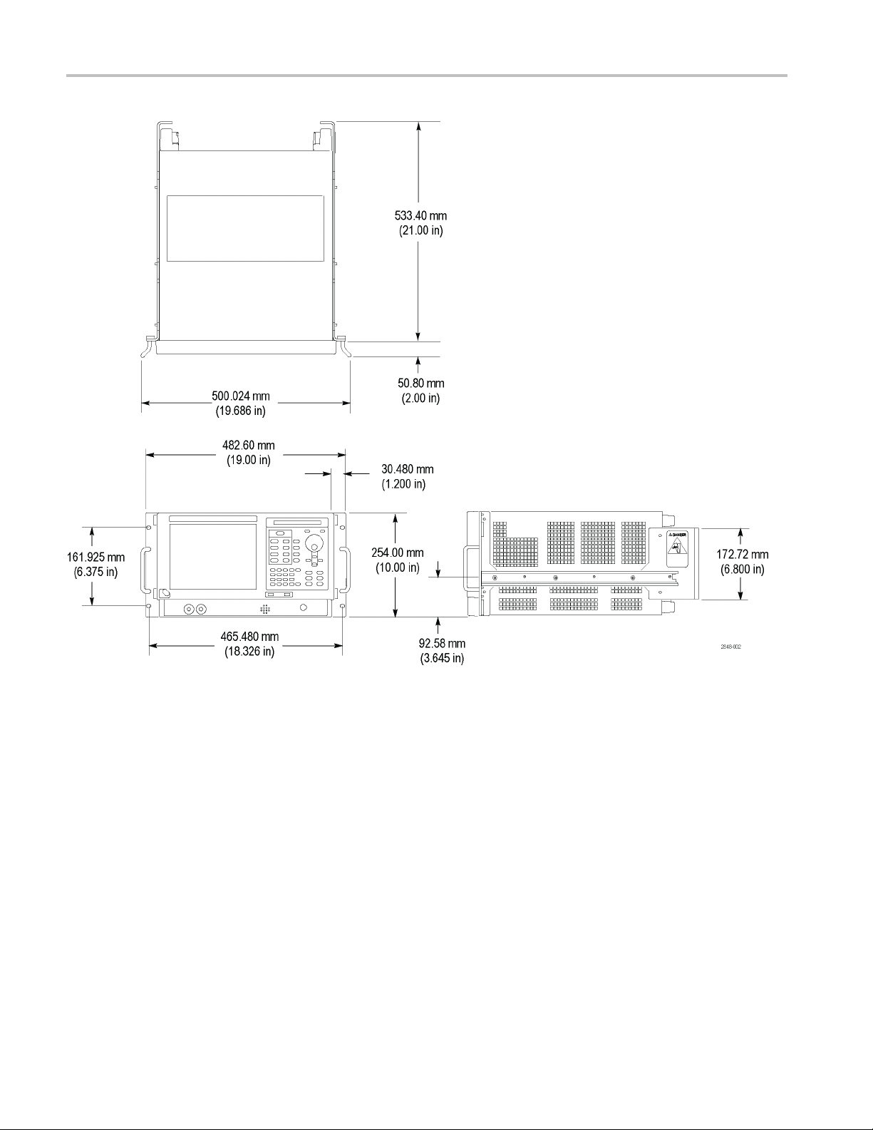
Figure 2: Instrument dimensions with rack adapter installed
6 RSA56KR Rackmount Installation Instructions
Page 11

Installation Instructions
This section contains all procedures needed to rackmount RSA6100A Series and
RSA5100A Series instruments.
Minimum Tool and Equipment List
The following tools are required to attach the rack-adapter kit hardware, install
cabling har
equipment cabinet. All tools are standard tools that are readily available.
Table 2: Tools required for installation
Item
no. Name Description
1
2
3
4
5
dware, and mount the rack-adapted instrument into a standard
Screwdriver
handle
(magnetic)
T-15 TORX
tip
5/32-in. hex
wrenc
T-10 T
tip
3/16-in. nut
driver
h
ORX
Installation Instructions
Torque driver handle. Accepts 1/4-in. hex-head driver tips
TORX-driver tip for T-15 size screws on the instrument covers
Hex wrench to remove Allen head screws at front of top cover
driver tip for T-10 size screw heads on the VGA cable
TORXconnector
Nut driver to remove the hex posts from the bracket (Slot PC
board)
These instructions are for qualified service personnel who are familiar with
vicing the product. If you need further details for disassembling or reas sembling
ser
the product, refer to the appropriate product manual. Contact your nearest
Tektronix Service Center or Tektronix Factory Service for installation assistance.
WAR NI NG . To prevent the rackmounted instrument from tipping forward onto the
operator, install the instrument so that the operator will be able to access all of its
rear devices without pushing down on the instrument.
Verify that the rack does not become unstable with the instrument fully extended.
Do not leave the i nstrument extende d when you are finished accessing the rear
panel.
RSA56KR Rackmount Installation Instructions 7
Page 12

Installation Instructions
Figure 3: Rackmount k it parts
Remove
Strip the Instrument for
ersion
Conv
8 RSA56KR Rackmount Installation Instructions
Equipment required. Torxdriver (Item 1) with T-15 and T-20 tips (Items 3 and
4), 5/32 hex wrench (Item 7).
NOTE. All parts removed from the instrument in this procedure should be retained
for later use. Store any parts not needed for r ackmounting in case you want to
vert back to a standard instrument configuration at a later time.
con
Right-side or left-side references in these instructions assume you are viewing the
strument from the front panel.
in
Page 13

Installation Instructions
1. Remove the powe
2. If it is installed, pull the front cover off the instrument.
3. Remove the two screws that se cure the plastic carrying handle to the side of
the instrument. (It is not necessary to remove the black metal handles.) (See
Figure 4.)
4. Remove four T-15 Torxdrive screws along each side and two 5/32 Allen head
screws near
secure the top and bottom covers to the instrument.
5. Remove the
back about 1 inch. Then pull out on the sides of the top cover outward,
flexing them slightly to clear the instrument chassis, and pull it away from the
instrument.
r cord.
the front edge of the top cover (next to the folding handles) that
top and bottom covers. Remove the top cover by pulling straight
RSA56KR Rackmount Installation Instructions 9
Page 14

Installation Instructions
Figure 4: Strip instrument for conversion
10 RSA56KR Rackmount Installation Instructions
Page 15

Installation Instructions
Figure
Install
5: Rackmount panel preassembly
NOTE. Preassemble all subparts on the right-and left-side panels before installing
the rackmount panels on the instrument. (See Figure 5.)
1. To install the bracket handle:
a. Install the bracket handle to the right-side rackmount panel.
b. Secure the bracket handle to the right-side rackmount panel using the two
10-32 x 0.375 flat head screws. Install the scr ews through the beveled,
recessed holes on the back of the flange. Apply 15 inch-lbs of torque to
the scr ews.
2. Install the right-side rackmount track over the three screw posts on the
right-side rackmount panel. Use the three 10-32 locking-nut washer
RSA56KR Rackmount Installation Instructions 11
Page 16

Installation Instructions
assemblies to s
applying 28 inch-lbs of torque.
CAUTION. To prevent the rackmount track from not locking, make sure the track
button latch is located towards the bottom of the rackmount panel. (See Figure 6.)
ecure the right-side rack track onto the rackmount panel,
Figure
3. Insta
4. Repeat steps 1 through 3, to install the left-side rackmount panel, substituting
6: Right inside track identification
ll the right-side rackmount panel assembly to the right side of the
instrument. Secure it by using the four 10-32 Truss head Phillips screws,
applying 28 inch-lbs of torque. (See Figure 7.)
left-side for the right-side.
12 RSA56KR Rackmount Installation Instructions
Page 17

Installation Instructions
Figure 7: Installation of rackmount assemblies
RSA56KR Rackmount Installation Instructions 13
Page 18

Installation Instructions
This completes
complete the installation, proceed to Rackmount the Rack-Adapted Instrument..
the installation of the rack-adapter hardware to the instrument. To
Rackmount the Rack-Adapted Instrument
This procedure describes how to assemble and install the slide-out tracks in the
equipment rack, and how to install the rack-adapted instrument in the rack.
The slide-out tracks permit the rack-adapted instrument to be extended out of the
rack for rear-panel and connector maintenance without removing the instrument
from the rack.
WARNING. If slide-out track assemblies are disassembled for maintenance, do not
interchange t he left and right inner tra cks when reinstalling them in the left and
right ou
feature of the tracks. Equipment could, when extended, come out of the slides and
fall from the rack, possibly causing personal injury and equipment damage.
WARNING. To prevent the rackmounted instrument from tipping forward onto the
operator, install the instrument so that the operator will be able to access all of its
rear devices without pushing down on the instrument.
ter tracks. If you do so, you will defeat the extension stop (safety latch)
Verify that the rack does not become unstable with the instrument fully extended.
Do not leave the instrument extended when finished accessing the rear panel.
NOTE. The rack hardware kit contains hardware needed for mounting the
instrument in s everal configurations. Not all of the hardware in the kit will be
needed.
TE. A standard equipment rack has rails with universal hole spacing. If
NO
you use a rack with other than universal hole spacing, you may have to drill
additional mounting holes in the rack.
14 RSA56KR Rackmount Installation Instructions
Page 19

Installation Instructions
Install Track A
instrument in Rack
ssembly and
Equipment Requ
tip (Item 2).
NOTE. The slide-out track assemblies that are included in this kit (See Figure 3
on page 8.) come partially assembled with the inner tracks inside of the outer
tracks. Leave them partially assembled to simplify their installation and to avoid
accidental swapping of their inner tracks. (See WARNING on the previous page.)
If assemblies are disassembled, you need to match left and right slides (See
Figure 8 on page 16.). (Note that when the left and right tracks are oriented as
shown, the
tracks.)
Procedure:
1. Assemble the slide-out track:
a. Identify the right versus left slide-out track assemblie s by finding the date
code label on each assembly. The assembly to be mounted in the left side
of the equipment rack (the side nearest the left side of the instrument when
it is r
right assembly has a date code ending with “RH”, for right hand.
ired. One screwdriver handle (Item 1), one number two Pozidriv
round cutout is below the square cutout at the end of the both inner
ackmounted) has a date code that ends with “LH,” for left hand. The
b. Meas
c. Align the rear bracket to the right slide-out track as shown (See Figure 8.).
d. Using a screwdriver with a number two Pozidriv tip, secure the rear
e. Repeat substeps c and d to assemble the left slide-out track assembly.
2. Mount the slide-out track assemblies, using the slide drawer hardware listed
in the kit parts list (See Figure 3.):
a. Select the mounting position in rack: Select two ½ inch spaced holes in
ure the distance between the front and rear rail of the equipment rack.
e the rear bracket has multiple pairs of mount-through holes. When
Not
aligning the bracket and track, be sure to select a pair of holes that mount
the rear bracket so the flange-to-flange distance (see figure) matches the
front rail to rea r rail spacing of the rackmount rack just measured.
bracket to the right slide out track using two screws (10-32) and a nut bar
as illustrated. Leave the screws loose so that the overall length o f the
slide-out track assembly can be adjusted when installing it in the rack.
the front rail. Verify that the 10.500 inch clearances exist relative to those
mounting holes. (See Figure 9 on page 17.)
RSA56KR Rackmount Installation Instructions 15
Page 20

Installation Instructions
Figure 8: Assembly of slide-out track assemblies
16 RSA56KR Rackmount Installation Instructions
Page 21

Installation Instructions
Figure 9: Vertical clearances for rack installation (left-front rail shown)
b. Select mounting method according to rack type:
To mount the slide-out tracks with their front and rear flanges outside
of the front and rear rails use Mounting Method A (See Figure 10.)
RSA56KR Rackmount Installation Instructions 17
Page 22

Installation Instructions
when doing subs
rails have untapped holes.
To mount with f
Method B outlined in the following figure. (See Figure 10.). This
mounting method assumes untapped holes.
c. Install in rack: Using the method and hardware determined from substep
b, secure the right slide-out track assembly to its front and rear rails. The
screws should be fully, but lightly, seated so mounting can be adjusted
later.
d. Fix the length of the slide-out track assembly: Tighten the screws,
applying 28 inch-lbs of torque, that were left loose in step 1, substep d, to
fix the front to rear flange spacing of t he slide-out track assembly.
e. Mount the left slide-out track assembly: Repeat substeps a through d to
mount the left slide-out track assembly.
tep c. Add a nut bar to the installation only if the
ront and rear flanges inside of rails use Mounting
18 RSA56KR Rackmount Installation Instructions
Page 23

Installation Instructions
Figure 1
0: Installation of slide-out track assemblies in rack (top view)
3. Mount i
WAR NI NG . To prevent the instrument from tipping or dropping onto the installers,
two or more people should install this instrument into the rack cabinet.
After completing the installation procedure, the installers should verify that the
instrument and r ack cabinet will not tip forward while the instrument is in the
extended position.
a. Install the instrument:
nstrument in rack:
Working from the front of the rack, slide the inner track of each
slide-out track assembly until it extends out the front of the rack.
Continue to slide them out until they lock.
Insert the left and right tracks that extend from the rear of the
instrument into the ends of the tracks just extended. Make sure the
tracks mounted on the instrument slip inside the inner tracks extended
arlier.
e
RSA56KR Rackmount Installation Instructions 19
Page 24

Installation Instructions
Slide the rear o
Push to release the button latches, located on the outside of each track,
and continue t
e. Level the rackmounted instrument:
Tighten the four screws that were left loose at the rear of the rack
when you did step 2, substep c, and then pull the instrument part way
out of the ra
Be sure the four screws that were left loose at the front of the rack are
loose enou
normal positions.
Retighte
the rack. If the tracks do not slide smoothly, readjust the level using
the method just detailed.
When leveling is completed, tighten the 10-32 screws using 28
inch-lbs of torque.
e. Secure the instrument and install the power cord:
Locat
or M6-20 oval head screws. Insert each screw through its nylon finish
washer as shown on the data sheet included with the hardware kit.
n the four screws and push the instrument all the way into
e and use one of the following types: 10-32 or 1 2-24 or M5-20
f the instrument backwards until it stops.
o slide the instrument all the way into the cabinet.
ck.
gh to allow t he slide-out track assemblies to seek their
Using a number two Phillips screwdriver, install the screw/washer
assembly in one of the two mounting holes in the right front bracket.
Repeat for the second mounting hole. Tighten b oth screws using 25
inch-lbs of torque.
Install the two remaining screw/washer as semblies in the left front
bracket using the method just described.
Install the optional front trim panel if the uncovered blank space
below the rack-mounted instrument is undesirable. Use the four 10-32
x 0.750 oval head Phillips drive screws with four nylon washers
to secure the front trim panel to the rack frame. (See Figure 3 on
page 8.)(See Figure 5 on page 11.)
Reinstall the power cord.
♦ End of document ♦
20 RSA56KR Rackmount Installation Instructions
 Loading...