


Tektronix RSA5100B Series Real-Time Signal Analyzers Quick Start Guide

x
RSA5100B Series
Real-Time Spectrum Analyzers
ZZZ
Quick Start User Manual
$
071-3224-12


xx
RSA5100B Series
Real-Time Spectrum Analyzers
ZZZ
Quick Start User Manual
www.tek.com
071-3224-12

Copyright © Tektronix. All rights reserved. Licensed software products are owned by Tektronix or its subsidiaries or suppliers, and are
protected by na
tional copyright laws and international treaty provisions.
Tektronix pro
previously published material. Specifications and price change privileges reserved.
TEKTRONIX and TEK are registered trademarks of Tektronix, Inc.
Planar Crown is a registered trademark of Aeroflex Inc.
LTE is a trademark of ETSI.
Bluetooth is a registered trademark of Bluetooth SIG, Inc.
ducts are covered by U.S. and foreign patents, issued and pending. Information in this publication supersedes that in all
Contacting Tektronix
Tektronix, Inc.
14150 SW Karl Braun Drive
P.O. Box 500
Beaverton, OR 97077
USA
For product information, sales, service, and technical support:
In North America, call 1-800-833-9200.
Worldwide, visit www.tek.com to find contacts in your area.

Warranty
Tektronix warrants that this product will be free from defects in materials and workmanship for a period of one (1) year from the date of
shipment. If any such product proves defective during this warranty period, Tektronix, at its option, either will repair the defective
product without charge for parts and labor, or will provide a replacement in exchange for the defective product. Parts, modules and
replacement products used by Tektronix for warranty work may be new or reconditioned to like new performance. All replaced
parts, modules and products become the property of Tektronix.
In order to obtain service under this warranty, Customer must notify Tektronix of the defect before the expiration of the warranty period
and make suitable arrangements for the performance of service. Customer shall be responsible for packaging and shipping the
defective product to the service center designated by Tektronix, with shipping charges prepaid. Tektronix shall pay for the return of the
product to Customer if the shipment is to a location within the country in which the Tektronix service center is located. Customer shall
be responsible for paying all shipping charges, duties, taxes, and any other charges for products returned to any other locations.
This warranty shall not apply to any defect, failure or damage caused by improper use or improper or inadequate maintenance and
care. Tektronix shall not be obligated to furnish service under this warranty a) to repair damage resulting from a ttempts by personnel
other than Tektronix representatives to install, repair or service the product; b) to repair damage resulting from improper use or
connection to incompatible equipment; c) to repair any damage or malfunction caused by the use of non-Tektronix supplies; or
d) to service a product that has been modified or integrated with other products when the effect of such modification or integration
increases the time or difficulty of servicing the product.
THIS WARRANTY IS GIVEN BY TEKTRONIX WITH RESPECT TO THE PRODUCT IN LIEU OF ANY OTHER WARRANTIES,
EXPRESS OR IMPLIED. TEKTRONIX AND ITS VENDORS DISCLAIM ANY IMPLIED WARRANTIES OF MERCHANTABILITY OR
FITNESS FOR A PARTICULAR PURPOSE. TEKTRONIX' RESPONSIBILITY TO REPAIR OR REPLACE DEFECTIVE PRODUCTS
IS THE SOLE AND E XCLU S IVE REMEDY PROVIDED TO THE CUSTOMER FOR BREACH OF THIS WARRANTY. TEKTRONIX
AND ITS VENDORS WILL NOT BE LIABLE FOR ANY INDIRECT, SPECIAL, INCIDENTAL, OR CONSEQUENTIAL DAMAGES
IRRESPECTIVE OF WHETHER TEKTRONIX OR THE VENDOR HAS ADVANCE NOTICE OF THE POSSIBILITY OF SUCH
DAMAGES.
[W2 – 15AUG04]


Table of Contents
Important safety information .......................................................................................................... iii
General safety summary......................................................................................................... iii
Service safety summary ......................................................................................................... v
Terms in this manual .......................................................................... . .. . . . . . . . . . . . . . . . . . . . . . . . . . . . . . . . . v
Symbols and terms on the product.................................................................... . .. . . . . . . . . . . . . . . . . . . . . . . . v
Compliance information ............................................................................................................... vi
EMC compliance ................................................................................................................. vi
Safety compliance............................................................................................................... vii
Environmental considerations ................................................................................................... ix
Preface................................................................................................................................. x
Key Features .....................................................................................................................x
Documentation ...................................................................................................................xi
Software Upgrades. . . . . . . . . . . . . . . . . . . . . . . . . . . . . . . . . .. . .. . ... ... ... .............................................................. xii
Conventions Used in This Manual.............................................................................................. xii
Installation.............................................................................................................................. 1
Before Installation................................................................................................................ 1
Standard Accessories. . . . . . . . . . . . . . . . . . . . . . . . . . . . . . . . . . . . . . . . . . . . . . . . . . . .. . ... ................................................... 1
Optional Accessories ............................................................................................................ 2
Options ........................................................................................................................... 3
Upgrades .. . . ............................ . ................................ . . ............................... . . . . . . . . . . . . . . . . . . . . . .. 3
How to manage the 5GNR analysis license . . . . . . . . . . . . . . . . . . . . . . . . . . . . . . . . . . . . . . . .. . ... ....................................... 3
Operating Considerations........................................................................................................ 7
Connecting to the Instrument .......................................................................... . ......................... 8
Activating Microsoft Windows 10 . . . . . . . . . . . . . . . . . . . . . . . . . . . . . . . . . . . . . . . . . . . . . . . . . . . ... .......................................... 8
Powering On the Instrument..................................................................................................... 9
Powering Off the Instrument..................................................................................................... 9
Removing the Power............................................................................................................. 9
Adding an External Monitor..................................................................................................... 10
Inspecting the Instrument....................................................................................................... 11
User Maintenance . ........................................... . . ...................... . .......................... . . .............. 12
ation.............................................................................................................................. 14
Oper
Getting Acquainted with Your Instrument ...................................................................... . ............... 14
Basic Concepts.................................................................................................................. 24
Navigating Displays............................................................................................................. 26
Selecting Displays...............................................................................................................28
Connecting a Signal.......................................................................................... . .................. 37
Starting and Stopping Acquisitions . .. . .. . .. . ... ... ............................................................................. 38
Markers.......................................................................................................................... 40
Touchscreen Actions............................................................................................................ 43
Printing .......................................................................................................................... 45
Saving Data ..................................................................................................................... 47
Recalling Data...................................................................................................................49
Table of Content
s
RSA5100B S eries Quick Start User Manual i

Table of Content
Specifications
Index
s
Advanced Techniques.. . . . . . . . . . . . . . . . . . . . . . . . . . . . . . . . . . . . . . ..................................... . . . . . . . . . . . . . . . . . . . . . . . . . . . . . . . 50
......................................................................................................................... 75
Specifications.................................................................................................................... 75
ii RSA5100B Series Q uick Start User Manual

Important safet
y information
Important saf
This manual contains information and warnings that must be followed by the user for safe operation and to keep the
product in a safe condition.
To safely perform service on this product, additional information is provided at the end of this section. (See page v,
Service safety summary.)
ety information
General safety summary
Use the product only as specified. Review the following safety precautions to avoid injury and prevent damage to this product
or any products connected to it. Carefully read all instructions. Retain these instructions for future reference.
Comply with local and national safety codes.
For c orrect and safe operation of the product, it is essential that you follow generally accepted safety procedures in addition
to the safety precautions specified in this manual.
The product is designed to be used by trained personnel only.
Only qualified personnel who are aware of the hazards involved should remove the cover for repair, maintenance, or
adjustment.
Before use, always check the product with a known source to be sure it is operating correctly.
This product is not intended for detection of hazardous voltages.
Use personal protective equipment to prevent shock and arc blast injury where hazardous live conductors are exposed.
While using this product, you may need to access other parts of a larger system. Read the safety sections of the other
component manuals for warnings and cautions related to operating the system.
When incorporating this equipment into a system, the safety of that system is the responsibility of the assembler of the system.
To avoid fire or personal injury
Use proper power cord. Use only the power cord specified for this product and certified for the country of use.
Do not use the provided power cord for other products.
Ground the product. This product is grounded through the grounding conductor of the power cord. To avoid electric
shock, the grounding conductor must be connected to earth ground. Before making connections to the input or output
terminals of the product, make sure that the product is properly grounded.
Do not disable the power cord grounding connection.
Power disconnect. The power cord disconnects the product from the power source. See instructions for the location. Do
not position the equipment so that it is difficult to disconnect the power cord; it must remain accessible to the user at all
times to allow for quick disconnection if needed.
Connect and disconnect properly. Do not connect or disconnect probes or test leads while they are connected
to a voltage source.
Observe all terminal ratings. To avoid fire or shock hazard, observe all ratings and markings on the product. Consult
the product manual for further ratings information before making connections to the product.
RSA5100B S eries Quick Start User Manual iii
Important safet
Do not apply a potential to any terminal, including the common terminal, that exceeds the maximum rating of that terminal.
The measuring terminals on this product are not rated for connection to mains or Category II, III, or IV circuits.
Do not operate without covers. Do not operate this product with covers or panels removed, or with the case open.
Hazardous voltage exposure is possible.
y information
Avoid expose
d circuitry.
Do not touch exposed connections and components when power is present.
Do not operate with suspected failures. If you suspect that there is damage to this product, have it inspected by
qualified service personnel.
Disable the product if it is damaged. Do not use the product if it is damaged or operates incorrectly. If in doubt about safety of
the product, turn it off and disconnect the power cord. Clearly mark the product to prevent its further operation.
Before use, inspect voltage probes, test leads, and accessories for mechanical damage and replace when damaged.
Examine the exterior of the product before y ou use it. Look for cracks or missing pieces.
Use only specified replacement parts.
Wear eye protection. Wear eye protection if exposure to high-intensity rays or laser radiation exists.
Do not operate in wet/damp conditions. Be aware that condensation may occur if a unit is moved from a cold to a
warm environment.
Do not operate in an explosive atmosphere.
Keep product surfaces clean and dry.
Remove the input signals before you clean the product.
Provide proper ventilation. Refer to the installation instructions in the manual for details on installing the product
so it has proper ventilation.
Slots and openings are provided for ventilation and should never be covered or otherwise obstructed. Do not push objects
into any of the openings.
Provide a safe working environment. Always place the product in a location convenient for viewing the display
and indicators.
Avoid improper or prolonged use of keyboards, pointers, and button pads. Improper or prolonged keyboard or pointer use
esult in serious injury.
may r
ure your work area meets applicable ergonomic standards. Consult with an ergonomics professional to avoid stress
Be s
injuries.
Use care when lifting and carrying the product. This product is provided with handles for lifting and carrying.
WARNING. The product is heavy. To reduce the risk of personal injury or damage to the device get help when lifting or
rrying the product.
ca
Use only the Tektronix rackmount hardware specified for this product.
iv RSA5100B Series Q uick Start User Manual
Servicesafetysummary
The Service safety summary section contains additional information required to safely perform service on the product. Only
qualified personnel should perform service procedures. Read this Service safety summary and the General safety summary
before performing any service procedures.
To avoid electric shock. Do not touch exposed connections.
Do not service alone. Do not perform internal service or adjustments of this product unless another person capable of
rendering first aid and resuscitation is present.
Disconnect power. To avoid electric shock, switch off the product power and disconnect the power cord from the mains
power before removing any covers or p
Use care when servicing with power on. Dangerous voltages or currents may exist in this product. Disconnect
power, remove battery (if applicable), and disconnect test leads before removing protective panels, soldering, or replacing
components.
Verify safety after repair. Always recheck ground continuity and mains dielectric strength after performing a repair.
Terms in this manual
anels, or opening the case for servicing.
Important safet
y information
These terms may appear in this manual:
WARNING. Warning statements identify conditions or practices that could result in injury or loss of life.
CAUTION. Caution s tatements identify conditions or practices that could result in damage to this product or other property.
Symbols and terms on the product
These terms may appear on the product:
DANGER indicates an injury hazard immediately accessible as you read the marking.
WARNING indicates an injury hazard not immediately accessible as you read the marking.
CAUTION indicates a hazard to property including the product.
When this symbol is marked on the product, be sure to consult the manual to find out the nature of the
potential hazards and any actions which have to be taken to avoid them. (This symbol may also be used
refer the user to ratings in the manual.)
The following symbol(s) m ay appear on the product:
to
RSA5100B S eries Quick Start User Manual v

Compliance info
rmation
Compliance in
This section lists the EMC (electromagnetic compliance), safety, and environmental standards with which the instrument
complies.
EMC compliance
EC Declaration of Conformity – EMC
Meets intent of Directive 2004/108/EC for E lectromagnetic Compatibility. Compliance was demonstrated to the following
specifications as listed in the Official Journal of the European Communities:
EN 61326-1 2006, EN 61326-2-1 2006. E MC requirements for electrical equipment for m easurement, control, and
laboratory use.
CISPR 11:2003. Radiated and conducted emissions, Group 1, Class A
IEC 61000-4-2:20
IEC 61000-4-3:2002. RF electromagnetic field immunity
IEC 61000-4-4:2004. Electrical fast transient / burst immunity
IEC 61000-4-5:2001. P ower line surge immunity
IEC 61000-4-6:2003. Conducted RF immunity
IEC 61000-4-11:2004. Voltage dips and interruptions immunity4,
123
formation
01. Electrostatic discharge immunity
5
6
7
EN 61000-3-2:2006. AC power line harmonic emissions
EN 61000-3-3:1995. Voltage changes, fluctuations, and flicker
European contact.
Tektronix UK, Ltd.
Western Peninsula
Western Road
Bracknell, RG12 1RF
United Kingdom
1
This product is intended for use in nonresidential areas only. Use in residential areas may cause electromagnetic interference.
2
Emissions which exceed the levels required by this standar
3
For compliance with the EMC standards listed here, high quality shielded interface cables s hould be used.
4
At the IEC 61000-4-11 Voltage-Interruption Transient Immunity test at 0% for 250 cycles, the EUT reboots and can take greater
than 10 seconds to recover.
5
Performance degradation information for the IEC 61000-4-3 test: Residual spurious signals can typically increase to -55 dBm with
exposure to the disturbancelevelsofthistest.
6
Performance degradation inf
either 55 dB below reference level or -75 dBm, with exposure to the disturbancelevelsofthistest.
7
Performance Criterion C applied at the 70%/25 cycle Voltage-Dip and the 0%/250 cycle Voltage-Interruption test levels (IEC
61000-4-11).
ormation for the IEC 61000-4-6 test: Residual spurious signals can typically increase to the worse of
d may occur when this equipment is connected to a test object.
vi RSA5100B Series Quick Start User Manual

Australia / New Zealand Declaration of Conformity – EMC
Complies with the EMC provision of the Radiocommunications Act per the following standard, in accordance with ACMA:
CISPR 11:2003. Radiated and Conducted Emissions, Group 1, Class A, in accordance with EN 61326-1:2006 and
EN 61326-2-1:2006.
Australia / New Zealand contact.
Baker & McKenzie
Level 27, AMP Centre
50 Bridge St
Sydney NSW 2000, Australia
reet
Safety compliance
This section lists the safety standards with which the product complies and other safety compliance information.
EU declaration of conformity – low v oltage
Compliance was demonstrated to the following specification as listed in the Official Journal of the European Union:
Compliance info
rmation
Low Voltage Directive 2006/95/EC.
EN 61010-1. Safety Requirements for Electrical Equipment for Measurement, Control, and Laboratory Use – Part
1: Gener
al Requirements.
U.S. nationally recognized testing laboratory listing
UL 61010-1. Safety Requirements for Electrical Equipment for Measurement, Control, and Laboratory Use – Part
1: General Requirements.
Canadian certification
CAN/CSA-C22.2 No. 61010-1. Safety Requirements for Electrical Equipment for Measurement, Control, and Laboratory
Part 1: General Requirements.
Use –
Additional compliances
IEC 61010-1. Safety Requirements for Electrical Equipment for Measurement, Control, and Laboratory Use – Part
1: General Requirements.
Equipment type
Test and measuring equipment.
afety class
S
Class 1 – grounded product.
RSA5100B S eries Quick Start User Manual vii

Compliance info
Pollution degree descriptions
A measure of the contaminants that could occur in the environment around and within a product. Typically the internal
environment inside a product is considered to be the same as the external. Products should be used only in the environment
for which they are r ated.
Pollution degree 1. No pollution or only dry, nonconductive pollution occurs. Products in this category are generally
encapsulated, hermetically sealed, or located in clean rooms.
Pollution degree 2. Normally only dry, nonconductive pollution occurs. Occasionally a temporary conductivity that is
caused by condensation m ust be expected. This location is a typical office/home environment. Temporary c ondensation
occurs only when the product is out of service.
Pollution degree 3. Conductive pollution, or dry, nonconductive pollution that becomes conductive due to condensation.
These are sheltered locations where neither temperature nor humidity is controlled. The a rea is protected from direct
sunshine, rain, or direct wind.
Pollution degree 4. Pollution that generates persistent conductivity through conductive dust, rain, or snow. Typical
outdoor locations.
Pollution degree rating
Pollution degree 2 (as defined in IEC 61010-1). Rated for indoor, dry location use only.
rmation
Measurement and overvoltage category descriptions
Measurement terminals on this product may be rated for measuring mains voltages from one or more of the following
categories (see specific ratings marked on the product and in the manual).
Category II. Circuits directly connected to the building wiring at utilization points (socket outlets and similar points).
Category III. In the building wiring and distribution system.
Category IV. At the source of the electrical supply to the building.
NOTE. Only mains power supply circuits have an overvoltage category rating. Only measurement circuits have a
measurement category rating. Other circuits within the product do not have either rating.
Mains overvoltage category rating
rvoltage category II (as defined in IEC 61010-1).
Ove
viii RSA5100B Series Q uick Start User Manual
Environmental considerations
This section provides information about the environmental impact of the product.
Product end-of-life handling
Observe the following guidelines when recycling an instrument or component:
Equipment recycling. Production of this equipment required the extraction and use of natural resources. The equipment
may contain substances that could be harmful to the environment or human health if improperly handled at the product’s
end of life. To avoid release of such substances into the environment and to reduce the use of natural resources, we
encourage you to recycle this product in an appropriate system that will ensure that most of the m aterials are reused
or recycled appropriately.
This symbol indicates that this product complies w ith the applicable European Union requirements according
to Directives 2012/19/EU and 2006/66/EC on waste electrical and electronic equipment (WEEE) and
batteries. For information about recycling options, check the Support/Service section of the Tektronix Web
site (www.tektronix.com).
Perchlorate materials. This product contains one or more type CR lithium batteries. According to the state
of Califo
www.dtsc.ca.gov/hazardouswaste/perchlorate for additional information.
rnia, CR lithium batteries are classified as perchlorate materials and require special handling. See
Compliance info
rmation
Restriction of hazardous substances
This product is classified as an industrial monitoring and control instrument, and is not required to c omply with the substance
restrictions of the recast RoHS Directive 2011/65/EU until July 22, 2017.
RSA5100B S eries Quick Start User Manual ix

Preface
Preface
This manual describes the installation and basic operation of the RSA5100B Series Real-Time Signal Analyzers. For more
detailed information, see the instrument help.
RSA5103B
RSA5106B
RSA5115B
RSA5126B
Key Features
The RSA5100B Series is a family of high-performance real-time signal analyzers. Key features include:
Reduce Time-to-Fault and increase design confidence with Real-time Signal Processing
Swept DPX spectrum enables unprecedented signal discovery over full frequency range
Advanced DPX including swept DPX, gap-free DPX spectrograms, and DPX zero span with real-time amplitude,
frequenc
y, or phase
DPX densi
Advance
25, 40, 8
Acquire
Wideba
Measur
Amplit
Corre
ty™ trigger on frequency domain events and distinguish between continuous signals vs infrequent events
d time-qualified, runt, and frequency-edge triggers act on complex signals as brief as 20 ns
5, 125, or 165 MHz acquisition bandwidths
more than 5 seconds at 165 MHz bandwidth
nd preselection filter provides image free measurements in entire analysis bandwidth up to 165 MHz
ements including channel power, ACLR, CCDF, OBW/EBW, spur search, EMI detectors
ude, frequency, phase vs. time, DPX spectrum, and spectrograms
lated multi-domain displays
x RSA5100B Series Quick Start User Manual

Documentation
The following documentation is available for your Tektronix RSA5100B Series Signal Analyzers. For the most current
documentation, refer to the Tektronix Web site.
To read about Use these documents
Installation and operation
(overviews)
Installation, safety,
compliance information
In-depth operation and
user interface help
Application examples Application Examples Manual
Programming commands Programmer Manual
Specifications and
performance verification
User service
Data security
Preface
Quick Start User Manual
The quick start user manual contains general information about how to put your instrument
into service and guides to user interface controls. These manuals are available as PDF
files.
English, Tektronix part number 071-3224-XX.
Japanese, Tektronix part number 071-3225-XX.
Simplified Chinese, Tektronix part number 071-3226-XX.
Russian, Tektronix part number 071-3227-XX.
Installation and Safety Instructions
The installation and safety instructions contain an introduction to the front and rear panel
of the instrument, basic connection, important safety, compliance, and environmental
information, and basic power specifications. This manual is available in printed form
and as a PDF file.
Instrument help
The instrument help contains detailed information about how to operate the instrument.
The help is available as a PDF file.
Tektronix part number 077-0899-XX.
This manual provides practical examples of using the analyzer to accomplish tasks. This
manual is available as a PDF file.
Tektronix part number 071-3283-XX.
This manual contains descriptions of programming commands and their use. This manual
is available as a PDF file.
Tektronix part number 077-0901-XX.
Specifications and Performance Verification Manual
This manual contains the instrument specifications and a procedure to check instrument
performance against warranted characteristics. This manual is available as a PDF file.
Tektronix part number 077-0900-XX.
Service Manual
This manual provides a list of replaceable parts, care and maintenance information, and
information for servicing the instrument to the module level. This manual is available
as a PDF file.
Tektronix part number 077-0903-XX.
Declassification and Security Instructions
This document helps customers with data security concerns to sanitize or remove memory
devices. This document is available as a PDF file.
Tektronix part number 077-0902-XX.
RSA5100B S eries Quick Start User Manual xi

Preface
Software Upgrades
Software option upgrades are available. Software upgrades for options become operational only after you enter a valid
option key for the specific analyzer model and serial number.
To check for upgrades:
1. Use your Web browser to go to www.tek.com/software.
2. Enter the product name (for example RSA5126B) to find available software upgrades.
Conventions Used in This Manual
The follow
Sequence
Step
ing icons are used throughout this manual:
Front panel
power
Connect
power
Network
PS2 SVGA USB
xii RSA5100B Series Quick Start User Manual

Installation
Before Installation
Unpack the instrument, and check that you received all items listed as Standard Accessories. Optional accessories and
instrument options are also listed in this section. Check the Tektronix website (www.tek.com) for the most current information.
Standard Accessories
Your instrument comes with the following accessories: product documentation (listed below), power cord, USB keyboard,
USB mouse, and instrument front cover.
The RSA5103B and RSA5106B also includes a BNC-N adapter.
The RSA5115B also includes a type N female Planar Crown R F input connector.
The RSA5126B also includes a 3.5 mm female Planar Crown RF input connector.
Product Documentation
Installation
RSA5100B Series Real-Time Signal Analyzers Quick S tart User Manual
RSA5100B Series Real-Time Signal Analyzers Installation and Safety Instructions
RSA5100B Series Real-Time Spectrum Analyzers Application Examples Manual
RSA5100B Series Help (accessible from the instrument and available as a downloadable PDF from www.tek.com)
Power Cords
The analyzer is shipped with one of the following power cord options. Power cords for use in North A merica are UL listed
and CSA certified. Cords for use in areas other than North America are approved by at least one authority acceptable in
the country to which the product is shipped.
International Power Plugs
Opt. A0 - North America power
Opt. A1 - Universal EURO power
Opt. A2 - United Kingdom power
Opt. A3 - Australia power
Opt. A4 - 240 V, North America power
Opt. A5 - Switzerland power
Opt. A6 - Japan power
Opt. A10 - China power
Opt. A11 - India power
RSA5100B S eries Quick Start User Manual 1

Installation
Opt. A12 - Brazil power
Opt. A99 - No power cord
Optional Acce
RTPA2A – Real-Time Spectrum Analyzer Probe Adapter; Supports TekConnect probes P7225, P7240, P7260, P7313,
P7313SMA, P7330, P7340A, P7350, P7350SMA, P7360A, P7380A, P7380SMA, P7500 Series.
SignalVu-PC – Offline analysis software based on the RSA5000/6000 Series platform.
RSAVu – Offline analysis software based on the RSA3000 platform for analysis supporting 3G wireless standards
Planar Crown 3.5 mm female connector, Tektronix part number 131-9062-00.
Planar Crown 3.5 mm male connector, Tektronix part number 131-8822-00.
Planar Crown Type N female connector, Tektronix part number 131-4329-00.
Planar Crown SMA female connector, Tektronix part number 131-8689-00.
Transit Case – Tektronix part number 016-1963-00.
Rackmount Retrofit - RSA56KR.
ssories
2 RS A5100B Series Quick Start User Manual

Options
See the RSA5000B datasheet at www.tek.com for a current list of available options you can add to your analyzer.
Upgrades
RSA5BUP SPARE-WIN10 – Adds an additional removable solid-state hard drive. Windows 10 and instrument software
pre-install
Installation
ed.)
RSA5BUP WIN
preinstalled.
RSA5BUP WIN10INT– An internally mounted drive. The Windows 10 operating system and instrument software is
preinstalled.
NOTE. Wind
How to man
The 5GNR Analysis option provides 5GNR analysis capabilities. To use the option, it must first be activated on the
instrument. Activation requires an activation c ode that you will receive from Tektronix. (The code is 20 digit alphanumeric
characters separated by a hyphen between every four characters). The following procedures show you how to activate or
deactivate 5GNR Analysis.
5GNR Analysis activation
1. On the T
will appear.
10REM– A removable solid-state drive. The Windows 10 operating system and instrument software is
ows 1 0 requires activation to operate in Activated mode. (See page 8, Activating Microsoft Windows 10.)
age the 5GNR analysis license
ools menu, click Manage 5GNR Analysis Activation....TheManage 5GNR Analysis Activation dialog box
RSA5100B S eries Quick Start User Manual 3
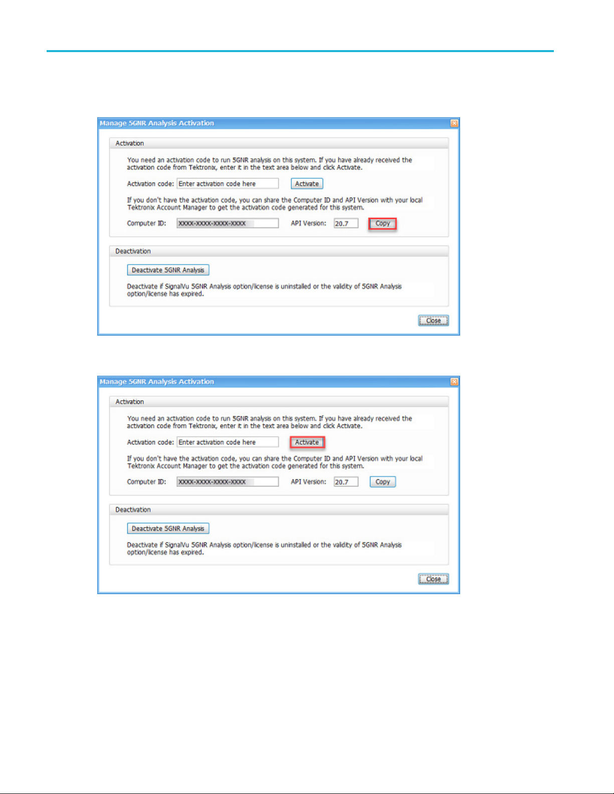
Installation
2. If you do not have the activation code, select Copy under Activation to copy the Computer ID and API Version. You
will then need t
o share those with your local Tektronix account manager to get the activation code generated for the
instrument. Once you have the code, proceed to the next step.
3. If you have the activation code that you received from Tektronix, enter it in the Activation code field and then select
Activate.
4 RS A5100B Series Quick Start User Manual
Installation
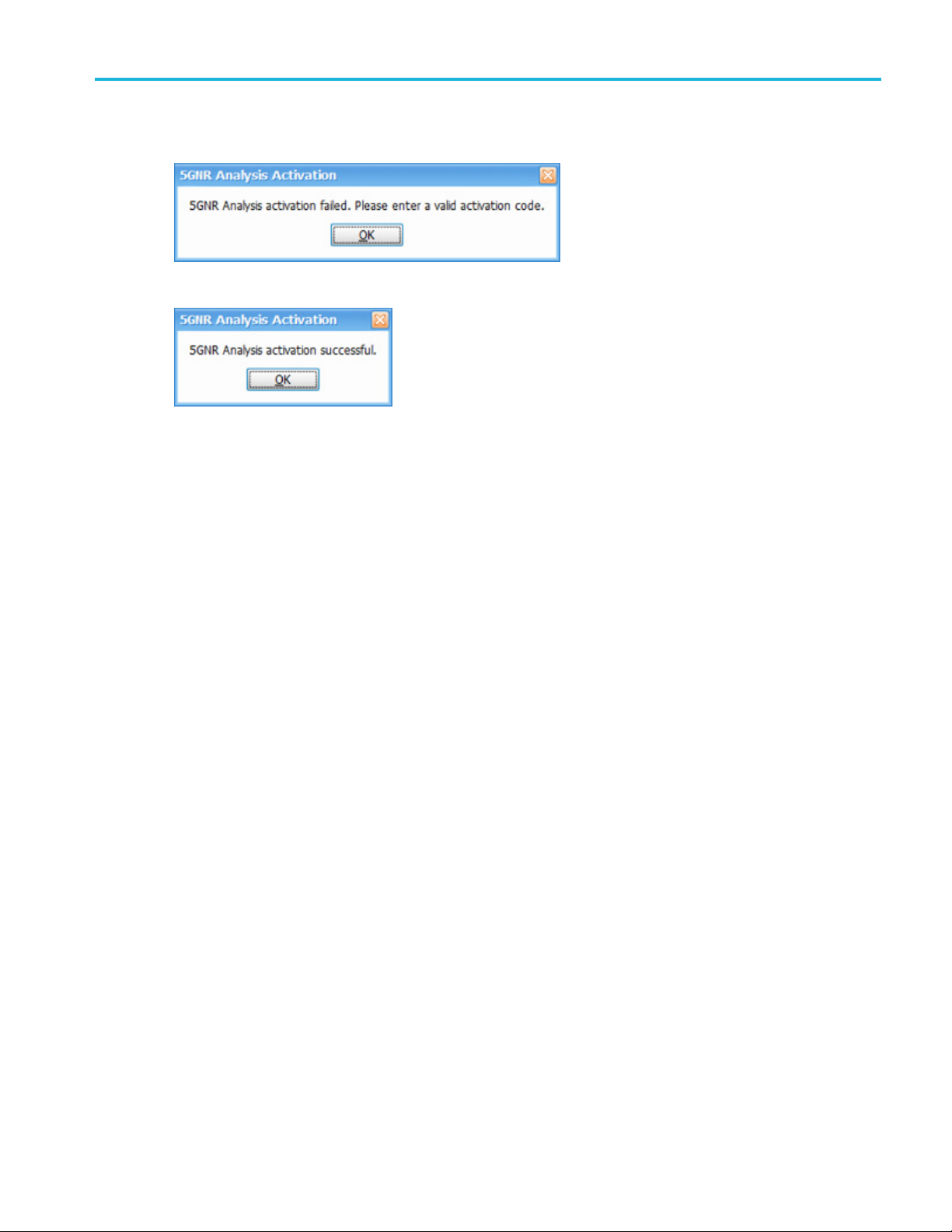
4. If you receive the “5GNR Analysis activation failed. Please enter a valid activation code.” message, click OK and then
contact your lo
5. If you receive the “5GNR Analysis activation successful.” message, click OK.
6. Close the Manage 5GNR Analysis Activation dialog box and restart the application.
cal Tektronix support or Account Manager to get the correct activation code.
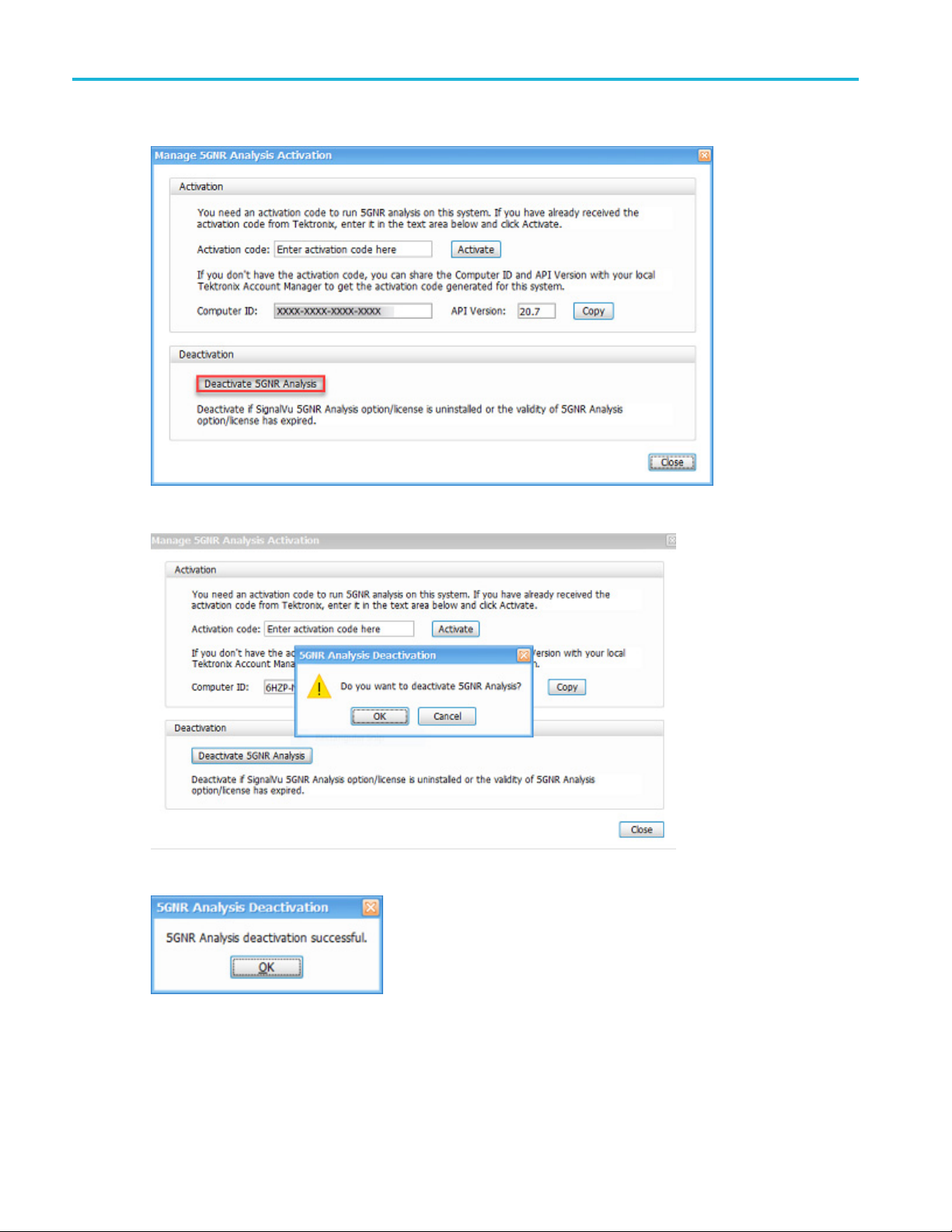
5GNR Analysis deactivation
1. On the Tools menu, click Manage 5GNR Analysis Activation....TheManage 5GNR Analysis Activation dialog box
will appear.
RSA5100B S eries Quick Start User Manual 5
Installation
2. Select Deactivate 5GNR Analysis under Deactivation.
3. Select OK in the popup window to continue with 5GNR Analysis deactivation.
4. If you receive the “5GNR Analysis deacti vation successful.” message, click OK.
5. Restart the application.
6 RS A5100B Series Quick Start User Manual
Operating Considerations
Power supply requirements
Source voltage and frequency Power consumption
100 – 240 V
115 V
RMS
, 400
, 50/60 Hz
RMS
Hz
Installation
450 W maximum (all models)
Environmen
Characteristic Description
Operating temperature +10 °C to +40 °C
Non-opera
Humidity
Operating
Altitude:
Operati
Non-operating
Cooling clearance
Bottom
Sides
tal requirements
ting temperature
ng
and back
-20°Cto+60°C
+40 °C at 95% relative humidity, meets intent of EN 60068-2-30.
Frequency amplitude response may vary up to ±3 dB at +40 °C and greater
than 45%
Up to 30
12190 m (40,000 ft)
20 mm (0.79 in)
50 mm (1.97 in)
relative humidity.
00 m (9843 ft)
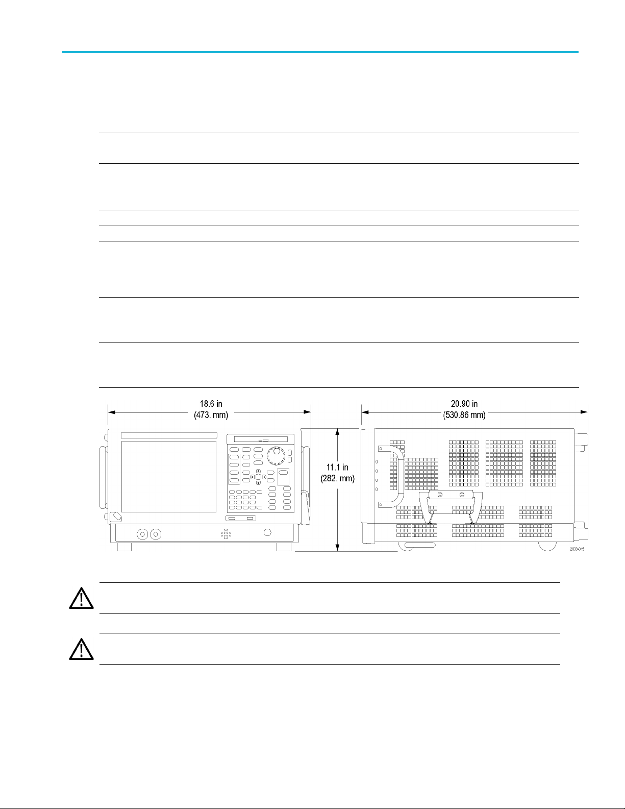
CAUTION. To ensure proper cooling, do not operate the instrument on its side. Operate the instrument only when it is
sting on i ts bottom feet or rear feet. Maintain at least 2 inches (5 cm.) clearance around ventilation openings.
re
WARNING. To avoid personal injury, take extra care when lifting or moving the signal analyzer. The instrument is heavy and
requires extra care when moving it.
RSA5100B S eries Quick Start User Manual 7
Installation
Connecting to the Instrument
Connecting to a Network
Connect your keyboard, mouse, printer, and other accessories to your instrument before applying power. (Accessories with
USB connecto
rs can be connected before or after applying power.)
You can conne
network for printing, file sharing, Internet
access, and other functions. C onsult your
network adm
Windows utilities to configure the instrument
for your network.
ct your instrument to a
inistrator and use the standard
Quick Tip
If you con
regular approved operating system updates, and using up-to-date antivirus software.
nect your instrument to a network, you should protect your instrument by using an internet firewall, installing
Activating Microsoft Windows 10
The version of Microsoft Windows 10 that ships with this product is shipped in Deferred Activation mode. Microsoft has
a default activation method that requires a connection to the Internet. If you do not have a connection, you can activate
Windows 10 by phone or you can continue to operate in Deferred Activation mode.
First time activation
You can activate Windows 10 two ways.
1. Connect to the Internet. Windows will automatically activate. You can also go to System Properties to connect and
activate.
2. Call Microsoft and speak with a representative to activate Windows 10. Contact information and a unique activation
(installation ID) will appear in a pop up window.
code
Activation with removable drives
If the SSD is removed from one analyzer and inserted into another analyzer, then the activation process will need to run
again. If analyzer 2 is not connected to the Internet, the activation will fail and an Activate Windows watermark will display on
the screen. To activate Windows and remove the watermark, you must connect to the Internet or call Microsoft.
8 RS A5100B Series Quick Start User Manual
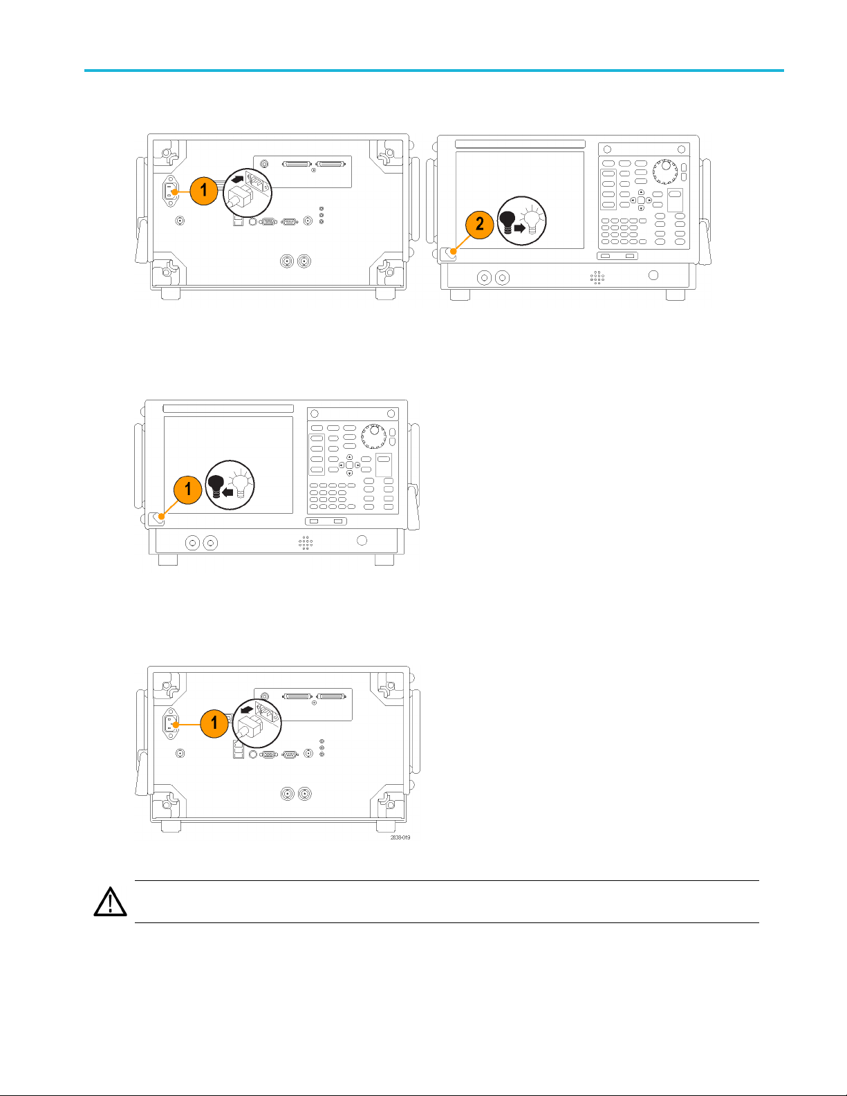
Powering On the Instrument
Powering Off the Instrument
Installation
Removing the Power
CAUTION. Do not remove the power cord while the instrument is running. P ower off the instrument first, allowing the
instrument to completely shut down before removing the power cord. The fans stopping is a good indicator.
RSA5100B S eries Quick Start User Manual 9
Installation
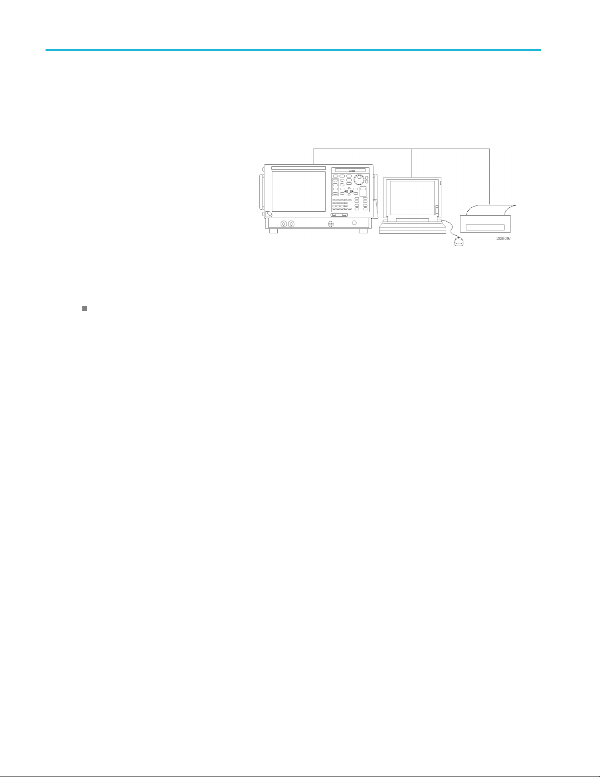
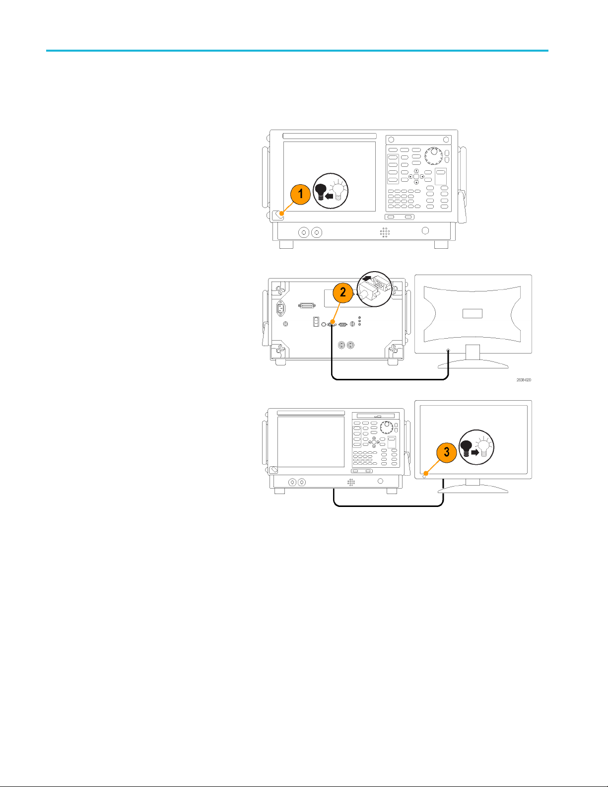
Adding an External Monitor
Use the following procedure to add an external monitor for dual monitor configuration. Both the analyzer and the second
monitor must have the color set to True Color.
1. Power on the analyzer.
2. Connect the external monitor to the
analyzer.
3. Power on
You can now navigate to the Display Settings in Windows 10 to extend the desktop to the connected monitor and set
display settings.
the external monitor.
10 RSA5100B Series Quick Start User Manual

Inspecting the Instrument
Run the diagnostics application (Tools > Diagnostics). If failures occur, perform the following steps to get more information
about them. You can also use the following steps as a detailed incoming inspection to verify the functionality of y our
instrument. If you want to check the accuracy specifications of your instrument, see the RSA5100B Series Real-Time
Signal Analyzers Specifications and P erformance Verification Technical Reference manual PDF located on the Product
Documentation CD.
1. Select Tools > Diagnostics.
Installation
2. On the Dia
Modules, All Tests.
3. Click Single Test.
4. Click RUN.
The instrument will run through the
tests o
or X icon will appear to the right
of each check box as that test is
comple
the test was passed. An X means
the test has failed.
5. For tests that require manual
inter
instructions to complete the tests.
NOTE. Select the Diagnostics Failure Information tab to see basic diagnostic failure information. Use the Windows Event
Viewer (Control Panel > System and Security > Administrative Tools > Event Viewer) to view failure history and nondiagnostic
ures reported by the application.
fail
gnostics tab, click All
ne at a time. A check mark
ted. The check icon means
vention, follow the on-screen
RSA5100B S eries Quick Start User Manual 11
Installation
User Maintenance
Caring for the Planar Crown RF Input Connector (RSA5115B/RSA5126B Only)
The Planar Crown input connector consists of two parts. The first part is the Planar Bulkhead, which is mounted in the
instrument front panel. The second part of the input connector is the Planar Crown, which mates to the Planar Bulkhead. The
Planar Crown c
an be easily changed should the connector become damaged or a different connector type be required.
No tools are r
sufficient to ensure an excellent connection.
When changing connectors, be careful not to touch inner surfaces of the connector halves.
Use only a 75% isopropyl alcohol solution to clean the Planar Crown connector, if needed. Do not use tap water to clean the
connector. Do not submerge the connector in a cleaning solution. Do not use abrasive compounds to clean the connector.
Cleaning Y
Clean the exterior surfaces of the chassis with a dry lint-free cloth or a soft-bristle brush. If any dirt remains, use a cloth or
swab dipped in a 75% isopropyl alcohol solution. Use a swab to clean narrow spaces around controls and connectors. Do
not use abrasive compounds on any part of the instrument because they might damage the instrument.
CAUTION. Avoid getting moisture inside the instrument during exterior cleaning; use just enough moisture to dampen the
cloth or swab. Do not wash the front-panel On/Standby switch. Cover the switch while washing the instrument. Use only
deionized or distilled water when cleaning. Use a 75% isopropyl alcohol solution as a cleanser and rinse with deionized
or distilled water. Do not use chemical cleaning agents; they might damage the chassis. Avoid chemicals that contain
benzene, toluene, xylene, acetone, or similar solvents.
CAUTION. To prevent damage to the flat panel display, do not use improper cleaning agents or methods. Avoid using
abrasive cleaners or commercial glass cleaners to clean the displ ay surface. Avoid spraying liquids directly on the display
surface. Avoid scrubbing the display with excessive force.
equired to remove or install the Planar Crown connector. A reasonable hand tightening of the connector is
our Instrument
Clean the d isplay surface by gently rubbing the display with a clean-room wipe. If the display is very dirty, moisten the wipe
with distilled water or a 75% isopropyl alcohol solution and gently rub the display surface. Avoid using excess force; this
might damage the display surface.
12 RSA5100B Series Quick Start User Manual