

Page 1

xx
RSA5100A Series
ZZZ
Real-Time Signal Analyzer
Service Manual
*P077052201*
077-0522-01
Page 2

Page 3

xx
RSA5100A Series
ZZZ
Real-Time Signal Analyzer
Service Manual
www.tektronix.com
077-0522-01
Page 4

Copyright © Tektronix. All rights reserved. Licensed software products are owned by Tektronix or its subsidiaries
or suppliers, and are protected by national copyright laws and international treaty provisions.
Tektronix products are covered by U.S. and foreign patents, issued and pending. Information in this publication
supersedes that in all previously published material. Specifications and price change privileges reserved.
TEKTRONIX and TEK are registered trademarks of Tektronix, Inc.
Contacting Tektronix
Tektronix, Inc.
14150 SW Karl Braun Drive
P.O. Box 5 0 0
Beaverto
USA
For product information, sales, service, and technical support:
n, OR 97077
In North America, call 1-800-833-9200.
Worl dwid e, visi t www.tektronix.com to find contacts in your area.
Page 5

Table of Contents
General safety summary .............. .................................. ................................ .......... iv
Service safety summary........................................................................................... vi
Preface ............................................................................................................. vii
Manual Content . ................................ ................................ ............................. vii
Manual Conventions................ ................................ .................................. ....... vii
Related User Documents.................................................................................... viii
Operating Information ............................................................................................. 1
Theory of Operation....................... ................................ ................................ ......... 3
General................... ................................ ................................ ....................... 4
Signal Path and Processing ................................................................................... 4
Display Panel.............. .................................. ................................ ................... 5
Front Panel ................ ................................ .................................. ................... 5
Rear Panel ......... .................................. ................................ ........................... 5
Power Supply................................................................................................... 6
Fans.............................................................................................................. 6
Adjustment Procedure................................. ................................ ............................. 7
Running Alignments........................ ................................ ................................ ... 7
Maintenance......................................................................................................... 9
Preventing ESD................................................................................................ 9
Inspection and Cleaning................ .................................. ................................ .... 10
Restoring the Instrument Software .................... ................................ .......................... 13
Restore the Microsoft Windows 7 Operating System..................... ................................ 13
Restoring the Instrument Product Software................................................................ 16
Get the Latest Software ...... ................................ .................................. .............. 16
Removal and Installation Procedures............ .................................. .............................. 17
Preparation............................. .................................. ................................ ...... 17
Trim, Cabinet, and Module Removal............................... ................................ ........ 19
Removal Procedures.......................................................................................... 22
Troubleshooting.................................................................................................... 26
Service Level .............................. ................................ .................................. .. 27
Check for Common Problems... ................................ .................................. .......... 27
Diagnostics .................................................................................................... 29
Replaceable Parts .................................................................................................. 45
Parts Ordering Information .................................................................................. 45
Using the Replaceable Parts List............................................................................ 46
RSA5100A Series Service Manual i
Page 6

Table of Contents
List of Figure
Figure 1: RSA5100A Series block diagram ........................ ................................ ............. 3
Figure 2: Po
Figure 3: Main customer replaceable modules... ................................ .............................. 21
Figure 4: Status indicator locations............ ................................ ................................ .. 28
Figure 5: External parts ............................... ................................ ............................ 48
Figure 6: Display, front panel, DVD, and removable hard drive............................... .............. 50
Figure 7: Modules............... ................................ ................................ .................. 52
Figure 8:
Figure 9: Upper deck fans, misc. cables.. ................................ .................................. .... 56
wer supply and HDD/DVD drive locations........ ................................ .............. 20
Power supply and internal hard drive.................................. .............................. 54
s
ii RSA5100A Series Service Manual
Page 7

List of Tables
Table 1: Rear panel connectors ...................... .................................. ........................... 5
Table 2: Ext
Table 3: Internal inspection check list............................. ................................ .............. 12
Table 4: Tools required for module removal ................................................................... 18
Table 5: Legend for accessing modules table ........................ ................................ .......... 19
Table 6: Accessing modules............................ .................................. ........................ 19
Table 7: Failure symptoms and possible causes........................ ................................ ........ 27
Table 8 : P
Table 9: Digital Interface board LED status indicators........................................................ 29
Table 10: Hardware module diagnostic error messages............... ................................ ........ 35
Table 11: Digital Interface Board diagnostic error messages..................................... ............ 35
Table 12: ADC Board diagnostic error messages.............................................................. 36
Table 13: DPSA Board diagnostic error messages ...... ................................ ...................... 37
Table
Table 15: LO1 Module diagnostic error messages............................................................. 39
Table 16: LO2/Reference Oscillator diagnostic error messages.................. ............................ 40
Table 17: Front Panel diagnostic error messages .................. ................................ ............ 43
Table 18: External parts................................. ................................ .......................... 47
Table 19: Display, front panel, DVD, and removable hard drive .................... ........................ 49
ble 20: Modules................................................................................................. 51
Ta
Table 21: Power supply and internal hard drive................................................................ 53
Table 22: Upper deck fans, misc. cables........................................................................ 55
ernal inspection checklist......................... .................................. ................ 11
ower Converter board LED status indicators....................................................... 29
14: RF Interface Board diagnostic error messages ..................................................... 38
Table of Contents
RSA5100A Series Service Manual iii
Page 8

General safety summary
General safet
To avoid fire or personal
injury
ysummary
Review the fo
this product or any products connected to it.
To avoid pot
Only qualified personnel should perform service procedures.
While using this product, you may need to access other parts of a larger system.
Read the safety sections of the other component manuals for warnings and
cautions r
Use proper power cord. Use only the power cord specified for this product and
certified for the country of use.
Ground the product. This product is grounded through the g rounding conductor
of the power cord. To avoid electric shock, the grounding conductor must be
connected to earth ground. Before making connections to the input or output
terminals of the product, ensure that the product is properly grounded.
Observe all terminal ratings. To avoid fire or shock hazard, observe all ratings
and markings on the product. Consult the product manual for further ratings
information before making connections to the product.
llowing safety precautions to avoid injury and prevent damage to
ential hazards, use this product only as specified.
elated to operating the system.
The inputs are not rated for connection to mains or Category II, III, or IV circuits.
Power disconnect. The power cord disconnects the product from the power source.
Donotblockthepowercord;itmustremain accessible to the user at all times.
Do not operate without covers. Do not operate this product with covers or panels
removed.
Do not operate with suspected failures. If you suspect that there is damage to this
product, have it inspected by qualified service personnel.
Avoid exposed circuitry. Do not touch exposed connections and components when
power is present.
Replace batteries properly. Replace batteries only with the specified type and
rating.
Use proper fuse. Use only the fuse type and rating s pecified for this product.
Wear eye protection. Wear eye protection if exposure to high-intensity rays or
laser radiation exists.
iv RSA5100A Series Service Manual
Page 9
General safety summary
Terms in this manual
Symbols and terms on the
product
Do not operate i
Do not operate in an explosive atmosphere.
Keep product surfaces clean and dry.
Provide prop
on installing the product so it has proper ventilation.
These terms may appear in this manual:
WAR NI NG .
in injury or loss of life.
CAUTION
damage to this product or other property.
These t
erms may appear on the product:
DANGER indicates an injury hazard immediately accessible as you read
the ma
n wet/damp conditions.
er ventilation. Refer to the manual's installation instructions for details
Warning statements identify conditions or practices that could result
. Caution statements identify conditions or practices that could result in
rking.
WARNING indicates an injury hazard not immediately accessible as you
the marking.
read
CAUTION indicates a hazard to property including the product.
The following symbol(s) may appear on the product:
RSA5100A Series Service Manual v
Page 10

Service safety summary
Service safet
ysummary
Only qualifie
safety summary and the General safety summary before performing any service
procedures.
Do not service alone. Do not perform internal service or adjustments of this
product unless another person capable of rendering first aid and resuscitation is
present.
Disconnect power. To avoid electric shock, switch off the instrument power, then
disconnect the power cord from the mains power.
Use care when servicing with power on. Dangerous voltages or currents may exist
in this p
test leads before removing protective panels, soldering, or replacing components.
To av oi
d personnel should perform service procedures. Read this Service
roduct. Disconnect power, remove battery (if applicable), and disconnect
d electric shock, do not touch exposed connections.
vi RSA5100A Series Service Manual
Page 11

Preface
This is the service manual for the RSA5100A Series Real-Time Signal Analyzers.
Read this preface to learn how this manual is structured, what conventions it uses,
and where you can find other information related to servicing this product.
Manual Cont
ent
Manual Conventions
Module
Plug-In Module
This manual contains information related to servicing an RSA5100A Series
Real-Time Signal Analyzer. For information related to installing and operating
the instr
user document as described in Related User Documents on the following page.
Be sure to
important information needed to perform the service correctly, safely, and
efficiently.
This manual uses certain conventions that you should become familiar with
before attempting service.
The term module refers to a collection of items that are replaceable as a unit. A
module may contain electrical a nd mechanical assemblies, circuit boards, and
interconnecting cables.
The term Plug-in Module refers to the units that plug into the Main Digital
Interface board.
ument, or for a list of instrument s pecifications, refer to the appropriate
read the introductions to all procedures. These introductions provide
his manual refers to any field-replaceable assembly or mechanical part by its
Replaceable Parts
Safety
RSA5100A Series Service Manual vii
T
name or generically as a replaceable part. In gene ral, a replaceable part is any
circuit board or assembly that is listed in the Replaceable Parts section.
Symbols and terms related to safety appear in the General Safety Summary found
at the beginning of this manual. Be sure to read both the General Safety Summary
and Service Safety Summary before performing any service to this instrument.
Page 12

Preface
Related User Documents
The following related English user documents are available if you need more
information about operating the instrument. These documents are located on the
RSA5100A Series Real-Time Signal Analyzer User Documentation CD-ROM or
can be downloaded from the Tektronix Web site (www.tektronix.com/manuals).
RSA6100A Series Real-Time Spectrum Analyzers, RSA5100A Series Real-Time
Signal Analyzer Quick Start User Manual. This document provides the basic
informati
includes a listing of the available instrument options and accessories.
on you need to install and operate the instrument. The document
RSA5100A
Performance Verification Technical Reference (English). This document
contains the following technical information about the instrument:
Electrical and physical specifications, including a list of certifications
and compliances.
A performance verific ation procedure to check instrument performance
against guaranteed specifications.
RSA6100A S eries Real-Time Spectrum Analyzers, RSA5100A Series
Real-Time Signal Analyzer Programmer Manual (English). Describes the
GPIB instrument programming commands and interface.
RSA5100A Series Real-Time Signal Analyzer D eclassification and Security
Instructions (English). Provides instruction on how customers with data
security concerns can sanitize or remove memory devices from the instrument.
Series Real-Time Signal Analyzer Series Specifications and
viii RSA5100A Series Service Manual
Page 13

Operating Information
For information on installing and operating your RSA5100A Series Real-Time
Signal Analyzer, refer to the RSA6100A Series Real-Time Spectrum Analyzers,
RSA5100A Ser
ies Real-Time Signal Analyzer Quick Start User Manual.
RSA5100A Series Service Manual 1
Page 14

Operating Information
2 RSA5100A Series Service Manual
Page 15
Theory of Operation
This section provides a basic description of the Real-Time Signal Analyzer (RSA)
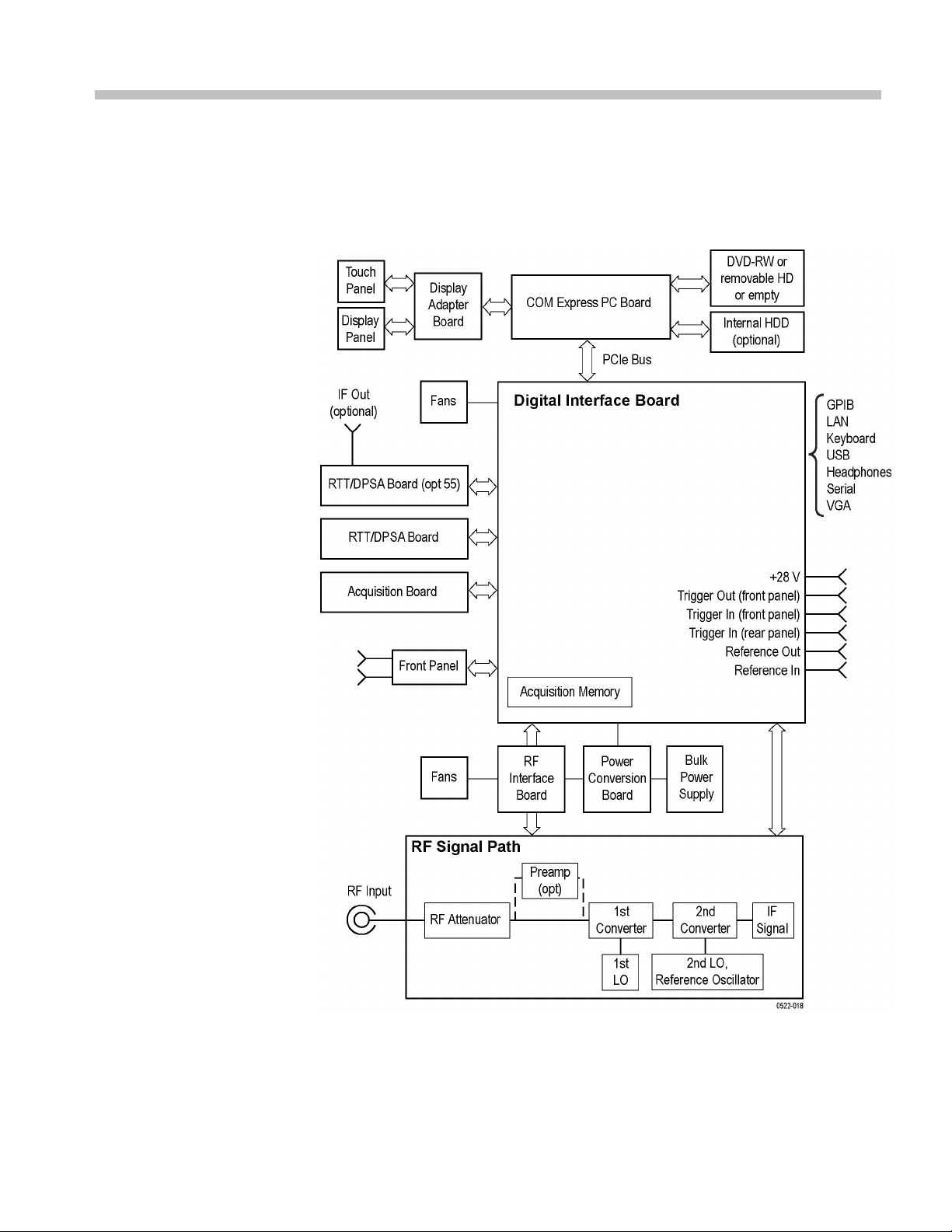
operation. Refer to the following block diagram of the instrument while reading
through this
section.
gure 1: RSA5100A Series block diagram
Fi
RSA5100A Series Service Manual 3
Page 16

Theory of Operation
General
A processor system controls the RSA5100A instrument. The instrument features
an XGA resolution flat-panel display, a transparent touch-screen, and a front-panel
with direct a
mouse or other pointing device, and/or a keyboard.
ccess to common RSA features. You can also use the RSA with a
The RSA uses
Signal Path and Processing
RF Signal Path
Acquisition System
Processor System
An RF sign
The RF signal path consists of an attenuator, optional preamplifier, 1st converter,
and 2nd c
replica of a portion of the input signal range to an intermediate frequency (IF)
which can be sampled by a high-dynamic-range A/D converter.
The processor system controls the RF signal path.
The acquisition system samples the IF signal and converts it to digital signals.
These
direct display or by measurement applications to provide signal quality metrics
to the user. T he acquisition data processing is performed by one of several
field-programmable gate arrays (FPGAs) under control of the processor. The
processor performs m easurement applications.
The processor system consists of a COM Express PCI-based processor board and
a Digital Interface board that connects the processor to the acquisition board.
the Microsoft Windows 7 operating system.
al enters the RSA through a direct N-type coaxial connection.
onverter. The purpose of the RF signal path is to translate a band-limited
digital signals are then filtered numerically and processed either for
Trigger Inputs
4 RSA5100A Series Service Manual
There are two coaxial trigger inputs. One is on the front panel below the display
and the other is on the rear panel. Both trigger inputs connect directly to the
Digital Interface board. Trigger signals are processed by an FPGA on the Digital
Interface board. The information from the trigger system is combined with
acquisition data by the processor system.
The Trigger Out signal is a coaxial connection on the front panel below the
display. The trigger out signal comes from the Acquisition Control FPGA,
through the Digital Interface board.
Page 17

Display Panel
Theory of Operation
Waveforms, spectral traces, measurement results, and control menus are displayed
on a 10.4 inch, color, active-matrix LCD display with touch panel.
Display System
Front Panel
Rear
Panel
Touch Panel
The display system consists of a display adapter board. The display adapter board
sends text and waveform information to the display panel.
The displa
y adapter board sends information from the touch panel to the processor.
The touch panel is listed as a USB HID device in the Window Device Manager
tool.
The processor system de tects changes in the front-panel switches and encoder. The
processor also turns the LEDs on and off. Communication between the processor
system and the front panel is performed over an internal USB connection.
The ON/STBY switch passes through the display adapter board, the PC carrier
board, the digital interface board, and to the PC board.
The DVD-RW and removable HDD (hard disk drive) communicate over a SATA
connection directly to the processor system.
The following table describes the rear panel connectors.
Table 1: Rear panel connectors
Input or
Name
Reference In
Reference
Out
LAN
USB Input/Output USB Two USB 2.0 connectors
Keyboard Input
VGA Output D-Sub
Serial Input/Output D-Sub Serial communications port (COM1) to
Trigger In Input
Output
Input
Output BNC 10 MHz output or loop-through of user
Input/Output
Connector
type Description
BNC External time-base reference. See data
sheet for signal quality requirements.
Reference In signal
RJ-45
PS/2 Keyboard-only PS/2 connector
BNC TTL Gate/trigger input signal
10/100/1000baseT Ethernet connector
External monitor connector
processor system
RSA5100A Series Service Manual 5
Page 18

Theory of Operation
Table 1: Rear panel connectors (cont.)
Power Supply
Input or
Name
Line In (blue)
MIC In (pink)
Headphone
+28 VDC Output BNC
GPIB Input/Output
Output
Input 3.5 mm
Input 3.5 mm
Output
Connector
type Description
Audio line input (disabled)
mono
Audio input signal (microphone)
mono
3.5 mm
stereo
IEEE-488
External headphone connection
Noise source drive power
General Purpose Interface Bus
The Power Conversion board provides instrument power. The Power Conversion
board consists of several switching supplies that translate and b alance the power
taken from the power supply module.
Power is distributed from the Power Conversion board to both the RF Deck and
the Digital Interface board.
The ON/STBY switch, located on the front panel, controls all of the power to the
instrument except for the part of the circuitry in the standby power supply.
Fans
Several fans provide cooling to the RSA:
Three fans are located in the RF Deck and are controlled by the RF Interface.
Two fans provide cooling for the Digital Deck of the instrument.
The Power Supply module has an internal fan.
The COM Express PC board has a fan that is controlled by the COM Express
PC board.
The optional DPSA board contains a fan.
6 RSA5100A Series Service Manual
Page 19

Adjustment Procedure
There are no physical user adjustment procedures for the RSA5100A Series
instruments. However, you can run alignments from the RSA5100A Series
application.
Running Ali
Alignment Status
gnments
Alignments are adjustment procedures run by the instrument using internal
reference signals and measurements, and do not require any external equipment or
connectio
There are two settings for Alignments:
If Automatically align as needed is selected, alignments run whenever the
Signal Analyzer detects a sufficient change in ambient conditions to warrant an
alignment.
If Run alignments only when “Align Now” button is pressed is selected,
the Signal Analyzer never runs an alignment unless you manually initiate an
alignment using the Align Now button.
NOTE
Automatically align as needed is not enabled.
The
alignment. If no message is displayed, you can assume that the Signal Analyzer is
properly aligned.
ns.
Automatically align as needed (Auto mode)
Run alignments only when the Align Now button is pressed
. There are a few critical adjustments that must run occasionally even if
Signal Analyzer displays a message on screen when it needs to run an
o initiate an alignment:
Initiating an Alignment
RSA5100A Series Service Manual 7
T
1. Select Setup > Alignments.
2. Click the Align Now button.
The Signal Analyzer runs an alignment procedure. The instrument displays
status messages as the alignment procedure is running. If the instrument fails the
alignment procedure, the instrument displays an error message. If the instrument
fails an alignment, run Diagnostics (Tools > Diagnostics) to determine why the
alignment failed.
NOTE. While an alignment is running, both the IF and IQ outputs are disabled.
Page 20

Adjustment Procedure
Alignments During
Warm-Up
Alignments During Normal
Operation
Alignments Are Not
ations
Calibr
Alignments are
oscillator alignments); the instrument uses default alignment values (if Auto mode
is selected).
NOTE. Instrument performance is not warranted during the specified 20 minute
warm-up period.
Once the instrument reaches operating temperature, a full alignment is run every
two hours (for up to two minutes). Alignments can run more frequently if the
operating temperature changes. If an alignment becomes necessary during a
measurement cycle (if Auto mode is selected), the measurement is aborted and
an alignm
measurement cycle restarts.
Alignme
reference signals and measurements. Calibrations can only be performed at a
Tektronix service center and require the use of traceable test equipment (signal
sources and measuring equipment) to verify the performance of the instrument.
nts are adjustment procedures run by the instrument using internal
not run during the 20 minute warm-up period (except for RF
ent procedure is run. Once an alignment procedure is completed, the
8 RSA5100A Series Service Manual
Page 21
Maintenance
This section contains the information needed to do periodic and corrective
maintenance on the instrument. The following subsections are included:
Preventing ESD –Generalinformationonpreventing damage by electrostatic
discharge.
Inspection and Cleaning – Information and procedures for inspecting the
instrument and cleaning its external and internal m odules.
Removal and Installation Procedures – Procedures for the removal of
defective modules and replacement of new or repaired modules. Also
included is a procedure for disassembly of the instrument for cleaning.
Troubleshooting – Information for isolating and troubleshooting failed
modules. Included are instructions for operating the instrument diagnostic
routines and troubleshooting trees. Most of the trees make use of the internal
diagnos
Repackaging Instructions – Information on returning an instrument for
servic
tic routines to speed fault isolation to a module.
e.
Preventing ESD
re servicing this product, read the Safety Summary and Introduction at the
Befo
front of the manual and the ESD information below.
CAUTION. Static discharge can damage any semiconductor component in this
instrument.
When perfo
adhere to the following precautions to avoid damaging internal modules and their
components due to electrostatic discharge (ESD).
1. Minimize handling of static-sensitive circuit boards and components.
2. Transpo
or on a metal rail. Label any package that contains static-sensitive boards.
3. Discha
wrist strap while handling these modules. Perform service of static-sensitive
modules only at a static-free work station.
4. Do not allow anything capable of generating or holding a static charge on the
work station surface.
rming any service that requires internal access to the instrument,
rt and store static-sensitive modules in their static protected containers
rge the static voltage from your body by wearing a grounded antistatic
5. Handle circuit boards by the edges when p ossible.
RSA5100A Series Service Manual 9
Page 22

Maintenance
6. Do not slide the
7. Avoid handling circuit boards in areas that have a floor or work-surface
Inspection and Cleaning
Inspection and Cleaning describes how to inspect for dirt and damage. It also
describes how to clean the exter ior and interior of the instrument. Inspection and
cleaning are done as preventive maintenance. Preventive maintenance, when done
regularly, may prevent instrument malfunction and enhance its reliability.
Preventive maintenance consists of visually inspecting and cleaning the
instrument and using general care when operating it.
How often preventive maintenance should be performed depends on the seve
of the environment in which you use the instrument. A proper time to perform
preventive maintenance is just before instrument adjustment.
General Care
The cabinet helps keep dust out of the instrument and should normally be in
place when operating the instrument.
circuit boards over any surface.
covering capable of generating a static charge.
rity
Interior Cleaning
Exterior Cleaning
Use a dry, low-velocity stream of air to c lean the interior of the chassis. Use a
soft-bristle, non-static-producing brush for c leaning around components. If you
must use a liquid for minor interior cleaning, use a 75% isopropyl alcohol solution
and rinse with deionized water.
WARNING. Before performing any procedure that follows, power down the
instrument and disconnect it from line voltage. Failure to do so could cause
personal injury, or death.
Clean the exterior surfaces of the chassis with a dry lint-free cloth or a soft-bristle
brush. If any dirt remains, use a cloth or swab dipped in a 75% isopropyl alcohol
solution. Use a swab to clean narrow spaces around controls and connectors.
Do not use abrasive compounds on any part of the chassis that may damage the
chassis.
Clean the On/Standby switch using a dampened cleaning towel. Do not spray or
wet the switch directly.
CAUTION. Avoid the use of chemical cleaning agents which might damage the
plastics u sed in this instrument. Use only deionized water when cleaning the menu
buttons or front-panel buttons. Use a 75% isopropyl alcohol solution as a cleaner
and rinse/wipe with deionized water. Before using any other type of cleaner,
consult your Tektronix Service Center or representative.
10 RSA5100A Series Service Manual
Page 23

Maintenance
Exterior Inspe
ction. Inspect the outside of the instrument for damage, wear, and
missing parts, using the following table as a guide. Immediately repair defects
that could cause personal injury or lead to further damage to the instrument.
Table 2: External inspection checklist
Item Inspect for Repair action
Cabinet, front panel, and
cover
Front-panel knob Missing, damaged, or loose
Connectors
Carrying handle, and
cabinet feet
Accessories
Cracks, scratches,
deformations, damaged
hardware
knob
Broken shells, cracked
insulation, and deformed
contacts; dirt in connectors
Correct operation Repair or replace defective
Missing items or parts of
items, bent pins, broken or
frayed cables, and damaged
connectors
Repair or replace defective
module
Repair or replace missing or
defective knob
Repair or replace defective
modules; clear or wash out
dirt
module
Repair or replace damaged
or missing items, frayed
cables, and defective
modules
anel Display Cleaning
Flat P
The display is a soft plastic display and must be treated with care during cleaning.
CAUTION. Improper cleaning agents or methods can damage the flat panel
display. Avoid using abrasive cleaners or commercial glass cleaners to cle an the
display surface. Avoid spraying liquids directly on the display surface. Avoid
scrubbing the display with excessive force.
Clean the flat panel display surface by gently wiping the display with a
clean-room wipe (such as Wypall Medium Duty Wipes, #05701, available from
Kimberly-Clark Corporation).
If the display is very dirty, moisten the wipe with distilled water or a 75%
isopropyl alcohol solution and gently wipe the display surface. Avoid using
xcess force or you may damage the plastic display surface.
e
CAUTION. To prevent moisture from getting inside the instrument during external
cleaning, use only enough liquid to dampen the cloth or applicator.
Interior inspection. To access the inside of the instrument for inspection and
cleaning, refer to the Removal a nd Installation Procedures in this section.
RSA5100A Series Service Manual 11
Page 24

Maintenance
Inspect the ins
ide of the instrument for damage and wear, using the following
table as a guide. Defects found should be repaired immediately.
CAUTION. To prevent damage from electrical arcing, ensure that circuit boards
and components are dry before applying power to the instrument.
Table 3: Internal inspection check list
Item Inspect for Repair action
Circuit boards
Resistors Burned, cracked, broken,
Solder connections Cold solder or rosin joints.
Capacitors
Wiring and cables Loose plugs or connectors.
Chassis Dents, deformations, and
Loose, broken, or corroded
solder connections.
Burned cir
Burned, broken, or cracked
circuit-run plating.
blistered condition.
Damaged or leaking cases.
Corroded solder on leads or
termina
Burned
wiring.
damag
cuit boards.
ls.
, broken, or frayed
ed hardware.
Remove and replace
damaged circuit board.
Remove and replace
damaged circuit board.
Resolder joint and clean
with isopropyl alcohol.
Remove and replace
damaged circuit board.
Firmly seat connectors.
or replace modules
Repair
with defective wires or
cables.
Straighten, repair, or replace
tive hardware.
defec
Cleaning procedure – interior. To clean the instrument interior, do the following
steps:
1. Blow off dust with dry, low-pressure, deionized air (approximately 9 psi).
2. Remove any remaining dust with a lint-free cloth dampened in isopropyl
alcohol (75% solution), and a clean lint-free cloth dampened in warm
deionized water. (A cotton-tipped applicator is useful for cleaning in narrow
aces and on circuit boards.)
sp
Lubrication. There is no lubrication required for this instrument.
12 RSA5100A Series Service Manual
Page 25

Restoring the Instrument Software
Restoring the
Instrument Software
CAUTION. The operating system (OS) restore process deletes all existing content
on a hard drive, including the instrument application software and saved data
and configuration files. Save or back up important data and configuration files to
external files or media be fore restoring the instrument OS.
Restore the Microsoft Windows 7 Operating System
You can re
instrument hard disk drive (preferred) or from the operating system restore DVD.
NOTE. The hard-disk-based OS restore is much faster (approximately 30 minutes)
than the DVD-based OS restore (approximately 1.5 hours).
NOTE. You will need to reload the instrument applications after restoring the OS.
(See page 16, Restoring the Instrument Product Software.)
Restoring the OS from the
Instrument Hard Disk
store the instrument operating system from either a partition on the
CAUTION. Save or back up important data and configuration files to external files
or media before restoring the instrument OS.
NOTE. Read through these instructions before you perform the procedure. There
is a 5-second time frame in which you must press the F5 key to access the restore
ogram.
pr
NOTE. You will need to reload the instrument applications after restoring the OS.
See page 16, Restoring the Instrument Product Software.)
(
RSA5100A Series Service Manual 13
Page 26

Restoring the Instrument Software
To restore t he o
perating system from the hard drive:
1. Restart the instrument. During the boot-up process you will see the following
message at the center of the screen:
Starting Acronis Loader...
press F5 for Acronis Startup Recovery Manager
2. Repeatedly press the F5 key until the Acronis True Image Tool opens. There
is an approximate 5-second time period from when the message appears until
the instrument proceeds with the normal instrument startup. If the instrument
does not open the Acronis application, power off the instrument, then power
on the instrument and try again.
3. Click Restore.
4. In the Confirmation dialog box, click Ye s to restore the instrument operating
system, or No to exit the restore process. The restore process takes
approximately 30 minutes; the actual time depends on the instrument
configuration.
5. Restore the instrument product software. (See page 16, Restoring the
Instrument Product Software.)
Restoring the OS from the
Restore DVD
CAUTION. Save or back up important data and configuration files to external files
or media b efore restoring the instrument OS.
CAUTION. To avoid malfunction, do not install any version of Microsoft Windows
7 that is not specifically provided by Tektronix for use with your instrument. The
version of Windows on this DVD is specially configured for the instrument. Other
available versions of Windows will not operate properly on the instrument. Do not
modify hardware device drivers, apply patches to operating system components,
or modify the system BIOS.
NOTE. You will need to reload the instrument applications after restoring the OS.
(See page 16, R estoring the Instrument Product Software.)
To restore the operating system from the OS Restore DVD’s:
1. If a keyboard is not installed, connect one to the instrument (the supplied
accessory keyboard plugs into the USB connector).
2. Power on the instrument.
14 RSA5100A Series Service Manual
Page 27

Restoring the Instrument Software
3. Option 56 only:
instrument.
4. Insert the Ope
drive.
5. Restart the
automatically.
6. Clickonthe
7. A dialog box requests if you are sure you want to restore and erase all data on
the drive.
8. Acronis will shortly prompt you for the disc with the last volume of the
image arc
9. Insert Disc 2 of 2, wait for the light on the front of the DVD player to stop
blinkin
10. Acronis will ask for Disc 1 again. Insert Disc 1 of 2, wait for the light on the
front o
11. Acronis will ask for Disc 2 again. Insert Disc 2 of 2, wait for the light on the
front
12. Acronis will ask for Disc 1 again. Insert Disc 1 of 2, wait for the light on the
fron
gandclicktheOK button.
f the DVD player to stop blinking and click the OK button.
of the DVD player to stop blinking and click the OK button.
t of the DVD player to stop blinking and click the OK button.
Connect a USB DVD-R drive to a USB port on the
rating System Recovery Media Disk 1 of 2 into the DVD
instrument. The Acronis TrueImage (OEM) window opens
Restore option to begin the restore.
Click Ye s .
hive.
Acronis will now begin writing the operating system to the hard drive.
13. 30 to 40 minutes into the process the instrument will ask for Disc 2. Insert
Disc 2 of 2, wait for the light on the front of the DVD player to stop blinking
dclicktheOK button.
an
14. Once the restore process is complete, Acronis will ask you whether you want
Shutdown or Reboot the instrument. Remove the restore media from
to
the DVD drive and return the media to safe storage. Choose the option to
Shutdown.
15. Restart the instrument.
16. Restore the instrument product software. (See page 16, Restoring the
Instrument Product Software.)
RSA5100A Series Service Manual 15
Page 28

Restoring the Instrument Software
Restoring the
Instrument Product Software
Use the RSA5100A Series Real-Time Signal Analyzer Product Software disc to
reinstall the signal analyzer product software if the software on your instrument
becomes corr
instrument.
To insta ll t
1. If a keyboard is not installed, connect one to the instrument (the supplied
accessory
2. If your instrument has a removable hard drive (Option 56), connect a USB
external
3. Power on the instrument.
4. After the instrument completes booting up, insert the Product Software disc in
the front-panel DVD drive (or external CD drive).
5. The Setup Wizard will start. Follow the instructions to install the product
software.
ON. When the Setup Wizard displays the Select Installation Folder screen,
CAUTI
the Setup Wizard allows you to select whether the software is installed for
Everyone or Just me. Always select Everyone to ensure proper software operation.
upted or you have performed an operating system restore on the
he product software:
keyboard plugs into the USB connector).
CD drive to the instrument.
Get the Latest Software
6. When the product software installation is complete, the Installation Complete
screen appears. Click Close to exit the Setup Wizard.
7. When the RSA5100A Setup dialog box appears, click OK.
e product software is now ready to use.
Th
or information on the latest software and critical updates, check the Tektronix
F
Web site (www.tektronix.com/software) and search for virus, patch, or critical
updates for your instrument.
16 RSA5100A Series Service Manual
Page 29

Removal and Installation Procedures
This subsection contains procedures for the removal and installation of all
customer-replaceable mechanical and electrical modules.
Preparation
WAR NI NG . Before doing this or any other procedure in this manual, read the
Safety Summary found at the beginning of this m anual. Also, to prevent possible
injury to service personnel or damage to the instrument components, read
Installation in the RSA5100A Series Real-Time Signal Analyzers Quick Start User
Manual, a
ESD in this section.
This subsection contains the following items:
vailable on the Web at www.tektronix.com/manuals, and Preventing
Preparatory information that you need to properly do the procedures that
follow.
Removal and Installation Procedures
A list of tools required to remove and disassemble all modules.
Procedures for removal and reinstallation of the electrical and mechanical
modules.
WAR NI NG . Before doing any procedure in this subsection, disconnect the power
cord from the line voltage source. Failure to do so could cause serious injury
or death.
NOTE. Read the Equipment Required section for a list of the tools needed to
remove and install modules in this instrument. (See Table 4 on page 18.) Read the
cleaning procedure before disassembling the instrument for cleaning.
RSA5100A Series Service Manual 17
Page 30

Removal and Installation Procedures
Equipment requ
ired. Most modules in the instrument can be removed with a
size T15 TORX screwdriver. Other tools needed for complete disassembly are
listed in the following table.
Table 4: Tools required for module removal
Item no. Name Description General tool number
1
2
3
4
5
6 Angle-tip Tweezers
7
8
9
Screwdriver handle A ccepts TORX-driver
T10 TORX tip Used for removing
T15 TORX tip Used for removing most
1/8 inch flat-bladed
screwdriver
#0 Phillips screwdriver Screwdriver for
3/16 inch open-end
wrench
5/16 inch open-end
wrench
MA-800G Soldering Aid
bits
instrument. screws
TORX-driver bit for
T10 size screw heads
instrument screws.
TORX-driver bit for
T15 size screw heads
Screwdriver for
unlocking cable
connectors
removing small phillips
screws, CDRW, and
hard drive
Used to remove front
panel knobs
Used to remove nut
posts
Used to remove nut
posts
Used to remove the
front panel trim
620-440
640-235
640-247
Standard tool
Standard tool
Standard tool
Standard tool
Standard tool
Standard tool
18 RSA5100A Series Service Manual
Page 31

Removal and Installation Procedures
Trim, Cabinet
, and Module Removal
Use the following two tables to determine items of the instrument that you will
need to remove to access replaceable parts. The first table lists items that may
need to be rem
oved before you can acces s a replaceable module. The second
table lists customer replaceable modules and which items must be removed to
access the replaceable module. The approximate location of the primary customer
replaceable modules is shown in the following figure. (See Figure 2 on page 20.)
Table 5: Legend for accessing modules table
A - Front Co
B - Front panel trim
C - Pouch
D - Cabin
E - Cabi
ver (if installed)
(if installed)
et, top
net, bottom
F - Interna
G - Intern
H-DVDDr
I-Remov
J-DVDD
al Cover, bottom
able HDD (if installed)
l Cover, top
ive ( if installed)
rive/Removable HDD Frame
K - Display Assembly
L - Front Panel
M - Inter
N - Power
O - Powe
nal HDD (if installed)
Conversion board
r Supply
Table 6: Accessing modules
Remove these items to access the module
Modules to replace A B C D E F G H I J K L M N O
Display Assembly
Front Panel
DVD Drive (if installed)
vable HDD Drive (if installed)
Remo
DVD Drive/ Removable HDD Frame
Digital Fan Tray (Upper Deck)
RF Deck Fan Tray
Real Time IQ/IF Output Acquisition
rd (if installed)
boa
/DPSA board
RTT
COM-Express PC board
Internal HDD (if installed)
Power Conversion board
Power Supply
RSA5100A Series Service Manual 19
Page 32

Removal and Installation Procedures
Figure 2: Power supply and HDD/DVD drive locations
20 RSA5100A Series Service Manual
Page 33

Removal and Installation Procedures
Figure 3: Main customer replaceable modules
RSA5100A Series Service Manual 21
Page 34

Removal and Installation Procedures
Removal Procedures
NOTE. Unless directed otherwise, installation is the reverse of the removal
procedure.
These procedures assume you have access to the module you are removing. Use
the tables to determine which trim and/or modules to remove to gain access. (See
Table 5 on pa
reference for customer replaceable module locations. (See Figure 2 on page 20.)
CAUTION. When removing or installing the keypad, make sure you do not touch
the switch contacts with your fingers. The oils in your fingers will degrade or
damage the switch contacts. To help prevent damage to the keypad use cotton
gloves when removing or installing the keyboard pad.
CAUTION. To avoid damage to the front panel Standby/On switch assembly, do
not set the Display module assembly on a work surface. S liding the instrument
over th
ge 19.) (See Table 6 on page 19.) A figure is also provided as a quick
e edge of the work surface could break off the On/Standby switch assembly.
Display
Front Panel
Perform these steps to remove the Display module:
1. Remove the four screws securing the display to the Main chassis; two on the
topandtwoontheleftside.
2. Disconnect the cables from the COM Express PC board and keep the cables
connected to the display assembly.
3. Gently remove the Display module from the Main chassis.
CAUTION. Be careful when removing and reinstalling the Display module cables.
If the connectors have bent pins or are installed incorrectly the Display may
e destroyed.
b
4. Disconnect the smaller Display cable from J2 on the Display Adapter board.
5. Disconnect the larger Display cable from J3 on the Display Adapter board.
Perform these steps to remove the Front Panel:
22 RSA5100A Series Service Manual
Page 35

Removal and Installation Procedures
Digital Deck Fans
DVD Drive
1. Disconnect the
board.
2. Remove the six
the top, two on the right side, and two on the bottom front.
3. Pull the Fro
Perform these steps to remove the fan assembly from the digital deck:
1. Unplug the fan control cable from the Digital Interface board connector,
marked Fan1 and Fan2.
2. Remove th
left side of the instrument.
3. Lift the
the card cage.
Follow these steps to remove the DVD drive (if installed):
1. Detach the DVD power and data cables from the COM Express PC board.
2. Carefully cut the zip tie from the DVD cables and pull the cables through
the chassis hole.
fan assembly up through the narrow slot betwe en the side panel and
Front Panel cable from connector 71 on the Digital Interface
T15 screws that secure the Front Panel to the chassis; two on
nt Panel assembly from the chassis.
e four T15 TORX screws securing the fan assembly, located on the
Removable Hard Disk Drive
Internal Hard Disk Drive
3. Remove the two screws from the front panel of the DVD.
4. Pull the DVD drive out from the Main chassis, being careful to feed the
cables as you pull.
5. Remove the four screws securing the DVD drive to the DVD drive bracket.
rform these steps to remove the removable hard disk drive (if installed):
Pe
1. Loosen the thumbscrews securing the drive to the front panel.
2. Grasp the drive assembly by the thumb screws and pull the assembly straight
out of the instrument.
3. Remove the four screws securing the hard drive to the bottom bracket.
Follow these steps to remove the internal hard disk drive:
NOTE. If you have a removable HDD mounted above the front panel, you will
not have an internal hard disk d rive.
RSA5100A Series Service Manual 23
Page 36

Removal and Installation Procedures
Power Supply
1. Remove the four
Power Supply shield.
2. Lift up hard di
hard disk drive.
3. Disconnect
4. Lifttheharddiskdriveupandremove it from the Signal Analyzer.
5. Remove the four screws securing the h ard drive to the bracket.
NOTE. It is not necessary to remove any installed HDD/DVD drives from the
chassis drive tray before removing the power supply . The power supply screws
can be accessed through the access holes in the drive tray. However, it might be
easier to disconnect the two-pin cable from the power supply to the conversion
board wi
Follow these steps to remove the power supply assembly:
1. Remove the six T15 screws securing the power supply access cover from
2. Remove the two T15 screws securing the right side of the power supply
th the drive tray removed.
the end of the Power Supply.
support bracket.
T15 screws securing the hard disk drive assembly to the
sk drive to access and remove the power/data cable from the
the video cables from the COM Express PC board.
3. Remove the power supply support bracket.
4. Disconnect the line trigger cable from J7 of the Power Conversion board.
5. Disconnect the power supply cable from the line filter cable.
6. Remove the two T15 screws securing the power supply shield tabs to the
top front chassis.
7. Pull the power supply assembly from the left side of the chassis. This will
take a little effort to pull, as the power supply must disconnect from the power
convertor board.
CAUTION. To prevent damage to the power convertor board connector, do not lift
the left end of the power supply while pulling.
24 RSA5100A Series Service Manual
Page 37

Removal and Installation Procedures
Power Conversion Board
COM Express PC Board
Perform these s
NOTE. Remove the Power Supply support bracket and the Power Supply before
removing the Power Conversion board.
1. Remove the cables connected to the Power Conversion board:
ATX POWER 2 0
ANALOG POWER 12-pin cable
RF PWR 50-pin ribbon c able
Flat ribbon cable 10-pin c able
Line Trigger Sense 2-pin cable
2. Remove the five T15 screws securing the Power Converter board to the
chassis.
3. Lift the Power Converter board from the Signal Analyzer.
Perform these steps to remove the COM Express PC board:
teps to remove the Power Conversion board:
-pin cable
1. Remove the two screws securing the COM Express PC board to the main
chassis card guide.
2. Disconnect all cables attached to the COM Express PC board.
3. Lift the latch levers on the top edge of the COM Express PC board assembly
to disconnect it from the Digital Interface board.
4. Lift the COM Express PC board from the Signal Analyzer.
RSA5100A Series Service Manual 25
Page 38

Troubleshooting
Troubleshooting
WARNING. Before doing this or any other procedure in this manual, read the
Safety Summa
injury to service personnel or damage to the instrument components, read
Installation in the RSA5100A Series Real-Time Signal Analyzers Quick Start User
Manual, available on the Web at www.tektronix.com/manuals, and Preventing
ESD in this section.
ry found at the beginning of this manual. Also, to prevent possible
Troublesh
faults to a module.
This subs
on the Real-Time Signal Analyzer, including PC troubleshooting and Windows
operating system skills. Details of PC and Windows operation and service are
not in this manual.
For assistance, please contact your local Tektronix Service Center.
ooting contains information and procedures designed to help you isolate
ection assumes that service personnel have the skills required to work
26 RSA5100A Series Service Manual
Page 39

Service Level
This section contains information and procedures designed to help you isolate
faulty modules in the RSA5100A Series R eal-Time Signal Analyzer. If a module
needstobere
this section.
Check for Common Problems
Use the following table to quickly isolate possible failures. The table lists
problems and possible causes. The list is not exhaustive, but it may help you
eliminate a problem that is quick to fix, such as a blown fuse or loose cable.
Table 7: Failure symptoms and possible causes
Troubleshooting
placed, follow the Removal and Installation Procedures,locatedin
Symptom Possibl
Instrument will not power on Power cord not plugged in
Front panel light comes on ( instrument
s on), but one or more fans will
power
not operate
No beeps on startup or multiple beeps
on startup (single beep is OK)
Flat panel display blank
e cause(s)
Faulty power supply (check Status LEDs)
Faulty power conditioner board
Faulty front panel power switch
Faulty display adapter board
Faulty fan cable
Defective fan assembly
Faulty power supply (check Status LEDs)
Faulty COM Express PC board
Faulty CPU
Digital Interface board problem
Faulty COM Express PC board
BIOS setting not Advanced Chipset Features
On Chip VGA > Enabled - Boot Display >
>CRT + LFP
Defective cable from PC Carrier board to
Display Adapter board
Defective backlighting display
Faulty display
Faulty digital interface board
Faulty display adapter board
RSA5100A Series Service Manual 27
Page 40

Troubleshooting
Table 7: Failure symptoms and possible causes (cont.)
Symptom Possible cause(s)
DVD-ROM related symptoms Defective DVD-ROM
Defective DVD-ROM drive cable
Defective DVD-ROM Adapter board
Incorrect DVD-ROM configuration in the BIOS
setup
Hard disk drive related symptoms
Defective hard disk d rive
Incorrect hard disk type selected in the BIOS
setup
Replaceable hard disk drive not installed
Power supply failure
Corrupted BIOS module fi rmware, reinstall
firmware
Loose cable
Status Indicator LEDs
Corrupted O S image
Check that the Status Indicator LEDs are lit on the Power Converter and Digital
rface boards to ensure the power supplies are operating. (See Figure 4.) (See
Inte
Table 8. ) (Se e Tabl e 9.)
Figure 4: Status indicator locations
28 RSA5100A Series Service Manual
Page 41

Troubleshooting
Table 8: Power C
LED Status Indication
DS171 STANDBY
DS172 -15 V OK
DS173 -8 V OK
DS174 +8 V OK
DS175 +15 V OK
DS176 +30 V OK
onverter board LED status indicators
Table 9: Digital Interface board LED status indicators
LED Status Indication
DS481 CLOCK FAIL (normally off)
DS482 +5 VSB OK
DS483 +5 V OK
DS484 +3.3 V OK
DS485 +2.5 V OK
DS486 +1.8 V OK
DS487 +1.5 V OK
DS488 FPGA INIT
DS489 FPGA DONE
DS4810 STATUS 0
DS4811 STATUS 1 (normally off)
DS911 +1.2 V OK
Diagnostics
This section describes how to use and interpret the embedded Diagnostics
Interface for both the Power On Self Tests (POST) and the Extended Diagnostics
tests. These tests determine whether there has been a module failure in the
instrument.
Power On Self Tests
(POST)
RSA5100A Series Service Manual 29
The instrument runs Power On Self Tests (POST) automatically every time
the instrument is powered up. If a failure is detected during this process, the
instrument displays the Power-On Self Tests tab of the Diagnostics window to list
which module(s) failed.
Page 42

Troubleshooting
Select th
information about failures.
All failure information is logged in the Windows Event Viewer. To access the
Windows Event Viewer, click the Event Viewer button on the Diagnostics Failure
Inf
portion of the Windows Control Panel.
e Diagnostics Failure Info tab in the Diagnostics window for more
o tab. The Windows Event Viewer is also available in the Administrative Tools
NOTE. Check the timestamp in the Event Viewer, as errors are stored on disk
and may be from earlier power cycles.
30 RSA5100A Series Service Manual
Page 43

Troubleshooting
Diagnostics Tests
The Diagnostic
instrument, including the POST tests. To run diagnostics:
1. Select Tools >
2. Select the Diagnostics tab and click All Modules, All Tests.
3. Click Single Test in the Repeat area.
s tab enables you to run any or all of the diagnostics tests in the
Diagnostics in the application menu bar.
4. Click RUN. The instrument performs the selected tests. For tests that require
manual intervention, follow the on-screen instructions to complete the tests.
Agreendotnexttoatestmeansthatthemarked test is currently running. If
the test completes successfully the green dot is replaced by a black check
mark. If the test fails, the green dot is replaced by a red X.
5. To run sp ecific tests, select those tests i n the list and use the Repeat segment
of the window to set the test run conditions. The Repeat controls (see the
following figure) let you:
A) Repeat the test(s) a specified number of times,
B) Repeat the test(s) until a failure occurs,
C) Repeat the test(s) continuously even if failures occur, or
D) Run the test(s) only one time.
RSA5100A Series Service Manual 31
Page 44

Troubleshooting
Microsoft Windows Event
Viewer
The Microsoft W
diagnostics failure information, with other messages regarding the operating
system. If there is not a shortcut to the Event Viewer on the desktop you can
access it by clicking the Event Viewer button on the Diagnostics Failure Info tab.
indows Event Viewer maintains a permanent record of instrument
To view the Diagnostics failure information, first click the Windows Logs icon
in the left frame (under Event Viewer (Local)). Then click the Applications
icon. The view changes to show the individual error reports, as shown in the
following figure.
Scroll through the Event list to locate error events. Pay attention to the date
and time stamps, as the information is a permanent record and shows failure
information from earlier diagnostic sessions.
Also note that the Signal Analyzer diagnostic errors are labeled as TekRSA in the
Source column, to differentiate them from operating system messages.
32 RSA5100A Series Service Manual
Page 45

Troubleshooting
Scroll through
and time stamps, as the information is a permanent record and shows failure
information from earlier diagnostic sessions.
Also note that the Signal Analyzer diagnostic errors are labeled as TekRSA in the
Source column, to differentiate them from operating system messages.
Clicking on an error message to display error information in the General or
Details tabs located below the list.
Double-click an error message to open a separate window for that error message.
The window shows the date and time the error message w as generated and the
source of the error message. The text of the error message is shown in the
iption area. The three buttons at the upper right let you navigate through the
Descr
error list (using the up and down arrows), or sends the record to the default printer.
the Event list to locate error events. Pay attention to the date
u scroll down in the error description, the event viewer always adds a line
If yo
that says “For more information, see Help and Support Center at” and includes a
link to Microsoft.com. Do not use this link, as Microsoft has no information on
Tektronix instrument error messages.
Click Help in the Event Viewer Menu bar to open the online help and learn m ore
information on using the Event Viewer.
RSA5100A Series Service Manual 33
Page 46

Troubleshooting
Diagnostic Test Error
Messages
The following t
recommended actions for each message.
Hardware Modu
Digital Interface board (See Table 11 on page 35.)
ADC board (See Table 12 on page 36.)
DPSA board (See Table 13 on page 37.)
RF Interface board (See Table 14 on page 38.)
LO1 Module (See Table 15 on page 39.)
LO2/Refe
Front Panel (See Table 17 on page 43.)
ables list the instrument diagnostics error messages, with
le (See Table 10 on page 35.)
rence Oscillator (See Table 16 on page 40.)
34 RSA5100A Series Service Manual
Page 47

Troubleshooting
Table 10: Hardw
Test Error m essage Recommended a
Hardware Init
Read
Programmable Part
Versions
are module diagnostic error messages
Uninitialized
See Event View
information
The Digital
found.
Acquisition Board not found. Send the instrument to a Tektronix Service Center for repair.
The DPSA Board was not found. Replace RTT/DPSA board.
Load Acqui
RF Interface Board not found or
FPGA Load failed.
LO1 not found or FPGA Load failed. Send the instrument to a Tektronix Service Center for repair.
L02/Reference Oscillator not found
or FPGA
The RF C
found or the FPGA was not loaded.
e to communicate with Digital
Unabl
interface board.
reading ID’s.
Error
Unable to communicate with PPC. Send the instrument to a Tektronix Service Center for repair.
er for more
Interface Board was not
sition Board Failed.
Load failed.
onverter board was not
The COM Expres
board. Restart the instrument and check the Event Viewer. If the
problem persists, send the instrument to Tektronix Service Center for
repair.
Send the ins
Send the instrument to a Tektronix Service Center for repair.
Replace RF Interface board.
Send the instrument to a Tektronix Service Center for repair.
Send th
Possible Digital Interface Board problem. Restart the Signal Analyzer.
If problem persists, return to Tektronix Service Center for repair.
Send the instrument to a Tektronix Service Center for repair.
trument to a Tektronix Service Center for repair.
e instrument to a Tektronix Service Center for repair.
ction
s PC is not communicating with the Digital Interface
Table 11: Digital Interface Board diagnostic error messages
Test Error m essage Recommended action
Digital Board ID
Verification
Load Test
Digital Board
Register R/W Test
Test
Digital Interface Board ID
Verification Failed.
Bad FPGA file path. Reinstall the RSA5100A product software.Digital Board FPGA
Exception in D igital Interface FPGA
Load.
Done bit not returned high.
Digital Interface alternating 1's and
0's R/W test failed.
Digital Interface reg R/W Walking
1's test failed.
Unable to communicate with Digital
Interface Board.
SRAM memory failure at “memory
address”.
Write value was “xxx”
Read Value w as “xxx”
Send the instrument to a Tektronix Service Center for repair.
Send the instrument to a Tektronix Service Center for repair.
Send the instrument to a Tektronix Service Center for repair.
Send the instrument to a Tektronix Service Center for repair.
Send the instrument to a Tektronix Service Center for repair.Digital Board SRAM
Send the instrument to a Tektronix Service Center for repair.
RSA5100A Series Service Manual 35
Page 48

Troubleshooting
Table 11: Digital Interface Board diagnostic error messages (cont.)
Test Error message Recommended action
Invalid number of return words. Send the instrument to a Tektronix Service Center for repair.Digital FIFO Test
Bad value in returned buffer. Send the instrument to a Tektronix Service Center for repair.
PPC returned unknown status. Send the instrument to a Tektronix Service Center for r epair.PPC POST Results
PPC did not return POST status. Send the instrument to a Tektronix Service Center for repair.
Digital Board
Acquisition Test
Digital Board
SDRAM Test
Digital Board
FLASH Test
Digital Board 28 Volt
Supply Test
Digital Board Audio
Test
Acquisition data at “offset xxx” was
not correct.
Write failure. SDRAM addr:
0xXXXX
Read failure. SDRAM addr:
0xXXXX
Failed bit exclusion Test with
pattern XXXX.
Validation failed at offset XXXX.
Blocks XXXX and XXXX are
mirrored.
Verification of this supply is done
by the operator.
No audio was heard.
Send the instrument to a Tektronix Service Center for repair.
Reseat the DIMM Acquisition memory module in the socket. If the
problem persists, send the instrument to a Tektronix Service Center
for repair.
Send the instrument to a Tektronix Service Center for repair.
If 28 V is not present at the rear-panel BNC connector, check the
+28 V at the test point on the power conversion board. If the 28 V
is not present, replace the power conversion board. If the +28 V is
present on the power conversion board, send the instrument to a
Tektronix Service Center for repair.
Verify that audio is not muted and level is set properly using Windows
Volume control. If this does not correct the problem, send the
instrument to a Tektronix Service Center for repair.
Table 12: ADC Board diagnostic e rror messages
Test Error message Recommended action
ADC board ID
Verification
ADC board FPGA
Load Test
ADC board Register
R/W Test
ADC board LVDS
Test
ADC Free Run
Trigger Test
Pattern Test
ADC Board Not Found in slot 1. Send the instrument to a Tektronix Service Center for repair.
Bad FPGA file path. The file was
not found in the directory.
The Main FPGA load failed. Send the instrument to a Tektronix Service Center for repair.
The Buffer FPGA load failed. Send the instrument to a Tektronix Service Center for repair.
DCM N ot locked. Send the instrument to a Tektronix Service Center for repair.
ADC R/W test FAILED. Send the instrument to a Tektronix Service Center for repair.
ADC LVDS test FAILED. Send the instrument to a Tektronix Service Center for repair.
ADC Free Run Trigger Test
FAILED.
Unexpected data at offset X. Send the instrument to a Tektronix Service Center for repair.ADC board Acq
Trigger timeout occurred.
Send the instrument to a Tektronix Service Center for repair.
Send the instrument to a Tektronix Service Center for repair.
Send the instrument to a Tektronix Service Center for repair.
36 RSA5100A Series Service Manual
Page 49

Table 12: ADC Board diagnostic error messages (cont.)
Test Error m essage Recommended action
ADC board Dither
Test
ADC board
Narrow Band CW
Acquisition Test
ADC board LF
Acquisition Test
ADC board WB IF
Acquisition Tes
Dither amplitude test - Failed
Dither frequency test - Failed
ADC Over range. Signal too strong. Run signal path test. If the signal path test passes
Signal below -50 dBm. Verify that the IF cable from the RF deck to the ADC board IF
No signal found in acquired
spectrum.
ADC Overrange Signal too strong. Run signal path test. If the signal path test passes
Signal below -50 dBm. Verify that the IF cable from the RF deck to the ADC board IF
No signal found in acquired
spectrum.
ADC Overrange Signal too strong. Run signal path test. If the signal path test passes
Signal below -50 dBm. Verify that the IF cable from the RF deck to the ADC board IF
No signal found in acquired
spectrum.
Send the instrument to a Tektronix Service Center for repair.
and this test fails, send the instrument to a Tektronix Service Center
for repair.
connector is firmly connected. Repeat the test, if the problem
persists, send the instrument to a Tektronix Service Center for repair.
Verify Normalization source is functional by running the Signal Path
test. If that test passes and this test still fails, send the instrument to
a Tektronix Service Center for repair.
Troubleshooting
able 13: DPSA Board diagnostic error messages
T
est
T
DPSA ID
Verification
DPSA FPGA Load
Test
rror m essage
E
DPSA Board ID Verification Failed. If ID was not found or a board other than the DPSA Board was found,
Bad DPSA FPGA file path. The file
was not found in the directory.
DPSA FPGA Load Failed. Replace the RTT/DPSA board. If the problem persists, send the
DCM N ot locked. Replace the RTT/DPSA board. If the problem persists, send the
ecommended action
R
Version/ID is nonfunctional. Replace the RTT/DPSA Board.
Reinstall the RSA5100A Series product software.
instrument to a Tektronix Service Center for repair.
instrument to a Tektronix Service Center for repair.
RSA5100A Series Service Manual 37
Page 50

Troubleshooting
Table 13: DPSA Board diagnostic error messages (cont.)
Test Error message Recommended action
DPSA Register R/W
Test
DPSA Frame
Transfer Test
DPSA LVDS Test The DPSA LVDS test failed. Replace the RTT/DPSA board. If the problem persists, send the
DPSA board FM/AM
Audio Test
14: RF Interface Board diagnostic error messages
Table
Read/Write test failed (returns read
and write values).
CT Board QDR Control Failure. Replace the RTT/DPSA board. If the problem persists, send the
FPGA File not found. Reinstall the RSA5100A Series product software.
FPGA Load Failed. Replace the RTT/DPSA board. If the problem persists, send the
Frame data test failed when looking
for incrementing pattern.
No audio was heard.
Replace the RTT/DPSA board. If the problem persists, send the
instrument to a Tektronix Service Center for repair.
instrument to a Tektronix Service Center for repair.
instrument to a Tektronix Service Center for repair.
Replace the RTT/DPSA board. If the problem persists, send the
instrument to a Tektronix Service Center for repair.
instrument to a Tektronix Service Center for repair.
Replace the RTT/DPSA board. If the problem persists, send the
instrument to a Tektronix Service Center for repair.
Test Error
terface ID Test
RF In
RF Interface FPGA
Load Test
RF In
FPGA Load failed. Replace RF Interface module.
message
terface Board not found.
mended action
Recom
he PPC load test. This will rerun hardware discovery. If error
Run t
persists, replace the RF Interface board.
38 RSA5100A Series Service Manual
Page 51

Table 14: RF Interface Board diagnostic error messages (cont.)
Test Error m essage Recommended action
RF Interface
Voltage/Current
test
The 30 Volt supply is over voltage.
The 30 Volt supply is under voltage.
The 8 Volt supply is over voltage.
The 8 Volt supply is under voltage.
The 2.5 Volt supply is over voltage.
The 2.5 Volt supply is under
voltage.
The 1.2 Volt supply is over voltage.
The 1.2 Volt supply is under
voltage.
The –8 Volt supply is over voltage.
The –8 Volt supply is under voltage.
The 8VSB supply is over voltage.
The 8VSB supply is under voltage.
Replace the Power Conversion board. If the problem persists,
replace the RF Interface board. If the problem persists, replace
the power supply. If the problem per sists, send the instrument to a
Tektronix Service Center for repair.
Replace the Power Conversion board. If the problem persists,
replace the RF Interface board. If the problem persists, replace
the power supply. If the problem per sists, send the instrument to a
Tektronix Service Center for repair.
Replace the Power Conversion board. If the problem persists,
replace the RF Interface board. If the problem persists, replace
the power supply. If the problem per sists, send the instrument to a
Tektronix Service Center for repair.
Replace the Power Conversion board. If the problem persists,
replace the RF Interface board. If the problem persists, replace
the power supply. If the problem per sists, send the instrument to a
Tektronix Service Center for repair.
Replace the Power Conversion board. If the problem persists,
replace the RF Interface board. If the problem persists, replace
the power supply. If the problem per sists, send the instrument to a
Tektronix Service Center for repair.
Replace the Power Conversion board. If the problem persists,
replace the RF Interface board. If the problem persists, replace
the power supply. If the problem per sists, send the instrument to a
Tektronix Service Center for repair.
Troubleshooting
le 15: LO1 Module diagnostic error messages
Tab
t
Tes
L01 ID Test
L01 FPGA Load
Test
L01 Register R/W
est
T
or message
Err
ard not found.
Bo
FPGA Load failed. Send the instrument to a Tektronix Service Center for repair.
Read /Write test failed. Send the instrument to a Tektronix Service Center for repair.
ommended action
Rec
n the PPC load test. This will rerun hardware discovery. If error
Ru
persists, send the instrument to a Tektronix Service Center for repair.
RSA5100A Series Service Manual 39
Page 52

Troubleshooting
Table 15: LO1 Module diagnostic error messages (cont.)
Test Error message Recommended action
L01 Voltage/Current
Test
Sum Loop Error voltage exceeds
High threshold
Sum Loop Error voltage exceeds
Low threshold
YTO Loop Error voltage exceeds
High threshold
YTO Loop Error voltage exceeds
Low threshold
Yig loop is unlocked.
Sum loop is unlocked. Send the instrument to a Tektronix Service Center for r epair.
15 V supply voltage is over/under
voltage.
12 V supply voltage is over/under
voltage.
8 V supply voltage is over/under
voltage.
5 V supply voltage is over/under
voltage.
3.3 V supply voltage is over/under
voltage.
L01 is over temp. Warning only.
Warning only.
Warning only.
Send the instrument to a Tektronix Service Center for repair.
Run the RF Interface ADC test to verify a power supply problem.
Check the Digital Interface board power supply status LEDs. (See
Table 9.)
Run the RF Interface ADC test to verify a power supply problem.
Check the Digital Interface board power supply status LEDs. (See
Table 9.)
Run the RF Interface ADC test to verify a power supply problem.
Check the Digital Interface board power supply status LEDs. (See
Table 9.)
Run the RF Interface ADC test to verify a power supply problem.
Check the Digital Interface board power supply status LEDs. (See
Table 9.)
Run the RF Interface ADC test to verify a power supply problem.
Check the Digital Interface board power supply status LEDs. (See
Table 9.)
able 16: LO2/Reference Oscillator diagnostic error messages
T
est
T
O2 ID Test
L
LO2 FPGA Load
Test
L02 Register R/W
Test
rror message
E
oard not found.
B
FPGA Load failed. Send the instrument to a Tektronix Service Center for repair.
Read /Write test failed. Send the instrument to a Tektronix Service Center for repair.
ecommended action
R
un the PPC load test. This will rerun hardware discovery. If error
R
persists, send the instrument to a Tektronix Service Center for repair.
40 RSA5100A Series Service Manual
Page 53

Table 16: LO2/Reference Oscillator diagnostic error messages (cont.)
Test Error m essage Recommended action
L02 Voltage/Current
Test
LO2 Phaselock
check
RF Converter ID
Test
RF Converter FPGA
Load Test
26 V supply voltage is over/under
voltage
9 V supply voltage is over/under
voltage
6 V supply voltage is over/under
voltage
5 V supply voltage is over/under
voltage
3.3 V supply voltage is over/under
voltage
–9 V supply voltage is over/under
voltage
L02 is over temp Warning only.
LO2 will not phase locked Send the instrument to a Tektronix Service Center for repair.
Board not found. Run the PPC load test. This will rerun hardware discovery. If error
FPGA Load failed. Send the instrument to a Tektronix Service Center for repair.
Replace the Power Conversion board. If the problem persists,
replace the RF Interface board. If the problem persists, replace
the power supply. If the problem per sists, send the instrument to a
Tektronix Service Center for repair.
Replace the Power Conversion board. If the problem persists,
replace the RF Interface board. If the problem persists, replace
the power supply. If the problem per sists, send the instrument to a
Tektronix Service Center for repair.
Replace the Power Conversion board. If the problem persists,
replace the RF Interface board. If the problem persists, replace
the power supply. If the problem per sists, send the instrument to a
Tektronix Service Center for repair.
Replace the Power Conversion board. If the problem persists,
replace the RF Interface board. If the problem persists, replace
the power supply. If the problem per sists, send the instrument to a
Tektronix Service Center for repair.
Replace the Power Conversion board. If the problem persists,
replace the RF Interface board. If the problem persists, replace
the power supply. If the problem per sists, send the instrument to a
Tektronix Service Center for repair.
Replace the Power Conversion board. If the problem persists,
replace the RF Interface board. If the problem persists, replace
the power supply. If the problem per sists, send the instrument to a
Tektronix Service Center for repair.
persists, send the instrument to a Tektronix Service Center for repair.
Troubleshooting
RSA5100A Series Service Manual 41
Page 54

Troubleshooting
Table 16: LO2/Reference Oscillator diagnostic error messages (cont.)
Test Error message Recommended action
RF Converter
Voltage/Current
test
Signal Path Test
15 V Supply Over/Under Voltage. Replace the Power Conversion board. If the problem persists,
replace the RF Interface board. If the problem persists, replace
the power supply. If the problem persists, send the instrument to a
Tektronix Service Center for repair.
8 V Supply Over/Under Voltage. Replace the Power Conversion board. If the problem persists,
replace the RF Interface board. If the problem persists, replace
the power supply. If the problem persists, send the instrument to a
Tektronix Service Center for repair.
2.5 V Supply Over/Under Voltage. Replace the Power Conversion board. If the problem persists,
replace the RF Interface board. If the problem persists, replace
the power supply. If the problem persists, send the instrument to a
Tektronix Service Center for repair.
1.2 V Supply Over/Under Voltage. Replace the Power Conversion board. If the problem persists,
replace the RF Interface board. If the problem persists, replace
the power supply. If the problem persists, send the instrument to a
Tektronix Service Center for repair.
–8 V Supply Over/Under Voltage. Replace the Power Conversion board. If the problem persists,
replace the RF Interface board. If the problem persists, replace
the power supply. If the problem persists, send the instrument to a
Tektronix Service Center for repair.
RF Atten test
10dB RF Atten signal path test
Failed.
2nd IF Atten test
2nd IF 10dB Atten s ignal path
Failed.
2nd IF Amp test
2nd IF Amp gain path Failed.
Preamp test
Preamp signal path FAILED
LF Attenuator test
LF 20dB LF Attenuator Failed.
LF Amp test
LF Amp signal path test Failed.
LF ADC test
RF Converter to LF ADC path
Failed.
NB ADC test
RF Converter to NB ADC path
Failed.
SAW filter test
1MHz saw filter test Failed.
Send the instrument to a Tektronix Service Center for repair.
Send the instrument to a Tektronix Service Center for repair.
Send the instrument to a Tektronix Service Center for repair.
Send the instrument to a Tektronix Service Center for repair.
Send the instrument to a Tektronix Service Center for repair.
Send the instrument to a Tektronix Service Center for repair.
Send the instrument to a Tektronix Service Center for repair.
Send the instrument to a Tektronix Service Center for repair.
Send the instrument to a Tektronix Service Center for repair.
42 RSA5100A Series Service Manual
Page 55

Troubleshooting
Table 16: LO2/Reference Oscillator diagnostic error messages (cont.)
Test Error m essage Recommended action
Step Attenuator test Step Attenuator Failed. Send the instrument to a Tektronix Service Center for repair.
IF Attenuator Test The IF attenuator Failed.
Preamp TestTest The Preamp Failed
Send the instrument to a Tektronix Service Center for repair.
Send the instrument to a Tektronix Service Center for repair.
Table 17:
Test Error mes
Front Panel Test
Front Panel diagnostic error messages
Front Pa
Front Pa
sage
nel LCD test failed.
nel Button test failed.
Recommen
Replace
Replace
the LCD display.
the front panel keypad.
ded action
RSA5100A Series Service Manual 43
Page 56

Troubleshooting
44 RSA5100A Series Service Manual
Page 57

Replaceable Parts
This section contains a list of the replaceable modules for the RSA5100A Series
Real-Time Signal Analyzers. Use this list to identify and order replacement parts.
Parts Ordering Information
Replacement parts are available through your local Tektronix field office or
representative.
Changes to Tektronix products are sometimes made to ac commodate improved
components as they become available and to give you the benefit of the latest
improvements. Therefore, when ordering parts, it is important to include the
followin
If you order a part that has been replaced with a different or improved part, your
local Tektronix field office or representative will contact you concerning any
change in part number.
ginformationinyourorder:
Part number
Instrument type or model number
Instrument serial number
Instrument modification n umber, if applicable
Module Servicing
Modules can be serviced by selecting one of the following three options. Contact
your local Tektronix service center or representative for repair assistance.
Module exchange. In some cases you may exchange your module for a
remanufactured module. These modules cost significantly less than new modules
d meet the same factory specifications. For more information about the
an
module exchange program, call 1-800-833-9200. Outside North America,
contact a Tektronix sales office or distributor; see the Tektronix Web site
(www.tektronix.com) for a list of offices.
Module repair and return. You may ship your module to us for repair, after which
we will return it to you.
New modules. You may purchase replacement modules in the same way as othe r
replacement parts.
RSA5100A Series Service Manual 45
Page 58

Replaceable Parts
Using the Replaceable Parts List
This section contains a list of the mechanical and/or electrical components that
are replaceable for the instrument. Use this list to identify and order replacement
parts. The following table describes each column in the parts list.
Column Column name Description
1
2 Tektronix part number
3 and 4
5
6
Figure & index number Items in this section are referenced by figure and index numbers to the exploded view
illustrations that follow.
Use this part number when ordering replacement parts from Tektronix.
Serial number Column three lists the serial number at which the part was first effective. Column
s the serial number at which the part was discontinued. No entry means that
four list
the part is usable for all serial numbers.
Qty The quantity of parts used.
Name & description An item name is separated from the description by a colon (:). Because of space
limitations, an item name may sometimes appear as incomplete. Use the U.S.
Federal
Catalog handbook H6-1 for further item name identification.
Abbreviations
viations conform to American National Standard ANSI Y1.1-1972.
Abbre
46 RSA5100A Series Service Manual
Page 59

Replaceable Parts
Table 18: Exter
nal parts
Tektronix
Fig. & index
number
5-
-1
-2
-3 211-1265-
-4 211-0720-
-5
-6 200-5173-00 1
-7
-8 211-1224-00 11
-9 348-1945-00 B010100 B010423 2
-10 348-1947-00 B010100 B010423 4
-11 348-1951-00 B010100 B010423 2
-12 211-1050-00 34
-13 200-4519-00 1
-14
-15 211-1224-00 3
-16 101-0152-00 1
-17 200-5149-00 1
-18 407-5530-01 2
-19 367-0542-00 2
-20 211-1230-00 4
-21 212-0650-00 4
part
number
200-5163-01 1
367-0528-00 1
407-4887-0
348-1648-00 4
200-5196-00 B010100 B010423 1
200-5196-01 B010423 1
333-4619-00 1
4677-00
333-
Serial no.
effective
0
00
00
Serial no.
discont'd Qty Name & description
COVER; TOP COSMETIC, ALUM; SAFETY CONTROLLED
HANDLE, CARRYING; DUAL DUROMETER MOLDED, SAFETY CONTROLLED
**ATTACHED PARTS**
1
2
4
1
BRACKET; HANDLE BASE, PC/ABS ALLOY
**END ATTACHED PARTS**
SCREW, MACHINE, 8-32 X 1.000L PNH, BLACK OXIDE, T20, NYLOK, STEEL
SCR, ASSEM WSHR; 6-32 X 0.500, PNH, STEEL, ZINC FINISH, T15 TORX DR, MACHINE
RSA5103A, RSA5196A
FOOT; REAR W/CORD WRAP, THERMO PLASTIC; SAFETY CONTROLLED
COVER; BOTTOM, INTERNAL; SAFETY CONTROLLED
COVER; BOTTOM COSMETIC; SAFETY CONTROLLED
A, RSA5106A
RSA5103
COVER; B
SCREW, 6
REAR FO
CUSHIO
FRONT
SCREW
COVER
COSM
RSA5103A, RSA5106A
COSMETIC FRONT ASSY; FRONT PANEL AND ACQUISITION TRIM
RSA5115A, RSA5126A
SCREW, 6-32 X 0.375L, PNH, BLACK, T15, NYLOC
TRIM, FRONT; TRIM ACQUISITION
COVER; TOP, INTERNAL; SAFETY CONTROLLED
BRACKET, MOUNTING; CARRYING HANDLE
HANDLE ASSY, CARRYING; AL, SS, BLACK
SCREW; 10-32X.500 SOC CAP,18-8 ZINC PLATED STEEL
SCREW, MACHINE; 10-32 X 0.437, FLH, 100 DEG, SST PSVT, POZ
OTTOM COSMETIC; SAFETY CONTROLLED
-32 X 0.375L, PNH, BLACK, T15, NYLOC
OT, STATIONARY, (2) NYLON W GLASS FILL
N, FOOT; SANTOPRENE, (4) BLACK
FOOT ASSEMBLY, FLIP (2)
, M ACHINE; 6-32 X 0.312 L, PNH, STEEL, ZINC FINISH, T15
, FRONT; PC ABS,17.420L X 8.670W X 2.000TH,TEK BLUE
ETIC FRONT ASSY; FRONT PANEL AND ACQUISITION TRIM
RSA5100A Series Service Manual 47
Page 60

Replaceable Parts
Figure 5: External parts
48 RSA5100A Series Service Manual
Page 61

Replaceable Parts
Table 19: Displ
ay, front panel, DVD, and removable hard drive
Tektronix
Fig. & index
number
6--1 200-5143-00 1
-2 407-5476-00 1
-3 119-7678-00 1
-4 065-0877-02 1
-5
-6 441-2620-01 1
-7
-8 407-5337-00 1
-9 174-5349-00 1
-10 174-5650-00 1
-11 211-0950-00 4
-12 211-1050-00 16
-13 614-1050-00 1
-14 174-5080-00 1
-15 174-5101-00 1
-16 878-0814-00 1
-17 878-0417-00 1
-18 878-0411-00 1
-19 260-2903-00 1
-20 333-4618-00 1
-21 366-A056-01 1
-22 650-5304-00 1
-23 259-0155-01 1
-24 407-5504-00 1
-25 119-7537-00 1
-26 119-7550-00 1
-27 407-5548-00 1
-28 878-0414-00 1
-29 174-5087-00 1
-30 174-5086-00 1
part
number
407-5473-00 1
211-1050-00 6
Serial no.
effective
Serial no.
discont'd Qty Name & description
COVER; DVD
BRACKET; DVD DRIVE
OPTICAL, CD-RW/DVD-R/RW DVD+R/RW, 16.7 MB/SEC, 650MEG/8.5GIG, SATA/ATAPI;
TEAC MODEL DV
DRIVE ASSEM
RSA5XXXA OPT 59
RSA5103A, RSA5106A
BRACKET; HARD DRIVE, 2.5 INCH REMOVABLE
CHASSIS; DRIVE BAY FRAME TOP
SCREW, MACHINE; 6-32 X 0.312 L, PNH, STEEL, ZINC FINISH, T15
HDD CABLE BRACKET
CABLE ASSY; SATA COMBO, HARD DRIVE CABLE WITH LATCH
CABLE, SATA-DVD, DATA AND POWER, SAFETY CONTROLLED
SCREW, MACHINE; M2X.4X3L, PHL, PNH, STEEL
SCREW, MACHINE; 6-32 X 0.312 L, PNH, STEEL, ZINC FINISH, T15
PANEL ASSEMBLY; FRONT, RSA5XXX SERIES
CA ASSY, SP; IDC, RIBBON, FRT PANEL TO DIG INTF, 2X10
CA ASSY, SP; IDC, RIBBON, AUDIO COM Express PC TO DIG INTERF, 2X5
CIRCUIT BRD ASSY; RSA ENCODER
15A, RSA5126A
RSA51
IT BD ASSY; USB I/O
CIRCU
UIT BD ASSY; FRONT PANEL CONTROL
CIRC
CH, KEYPAD FRONT PANEL
SWIT
T SUBPANEL ASSEMBLY
FRON
B; GENERAL PURPOSE
KNO
ULE ASSY; DISPLAY WITH 119755000 LCD
MOD
EX CIRCUIT; POWER SWITCH, W/LED
FL
ACKET, DISPLAY FRONT; SAFETY CONTROLLED
BR
UCH SCREEN ASSEMBLY, 10.4 IN, RESISTIVE, 5-WIRE, W/GASKETS
TO
SPLAY MODULE; LCD; 1024 X 768; 10.4 INCHES DIAGONAL, TFT, LED BACK LIGHT
DI
RACKET, DISPLAY
B
IRCUIT BD ASSY; INTERCONNECT DISPLAY ADAPTER BRD
C
A ASSY, SP; IDC, RIBBON, DISP ADAPT TO DIG INTERF, 2MM, 2X15
C
RSA5103A, RSA5106A
CA ASSY, SP; IDC, RIBBON, DISP ADAPT TO DIG INTERF, 2MM, 2X10
RSA5103A, RSA5106A
-W28S-Z3
BLY, WITH PACKAGING & COA; FIXED INTERNAL HARD DISK DRIVE,
RSA5100A Series Service Manual 49
Page 62

Replaceable Parts
Figure 6: Display, front panel, DVD, and removable hard drive
50 RSA5100A Series Service Manual
Page 63

Replaceable Parts
Table 20: Modul
Fig. & index
number
7-1
-2 407-5478-0
-3 211-1050-0
-4
-5
-6
-7
-8 407-5
-9 436-0
-10 664-
-11 200-
-12 211
-13 200
-14 200
5
-1
6
-1
es
Tektronix
part
number
878-0372-00 1
878-0831-00 1
039-0190-0
039-0209-00 1
119-7490-00 1
119-7683-00 1 FAN, 70MM X 70MM X 15MM, 12V
211-1346-00 4
211-1444-00 4
863-0
5898-04
4961-00
-0450-00
-5195-00
-4961-00
4-5106-01
17
7-5181-00
40
273-00
358-00
435-00
Serial no.
effective
0
0
0
Serial no.
discont'd Qty Name & description
CIRCUIT BOARD ASSY; COM EXPRESS PC BOARD, PB-FREE
RSA5105A, RS
CIRCUIT BOAR
RSA5115A, RSA5126A
1
10
1
1
1
1
1
1
4
1
1
2
1
BRACKET, COM EXPRESS CARRIER; SAFETY CONTROLLED
SCREW, MACHINE; 6-32 X 0.312 L, PNH, STEEL, ZINC FINISH, T15
PROCESSOR MODULE; PCI, SOM-5786
RSA5105A, RSA5106A
PROCESSOR MODULE; PCI, COM-E, MODIFIED ESM-GM45, BCM, MODULE ONLY
RSA5115A,
FAN, TUBE
W/LEADS; SAFETY CONTROLLED
RSA5105A, RSA5106A
RSA5115A, RSA5126A
SCREW, MACHINE, PANHEAD M3 X 0.5 X 26MM, PHILLIPS
RSA510
SCREW,
RSA5115A, RSA5126A
CIRCUIT BD ASSY; RTT/DPSA, PB-FREE
BRACKET, HEATSINK FAN
FAN ASSEMBLY
CIRCUIT BD ASSY; REALTIME I/Q OUTPUT (OPT 55)
COVER; REAR PANEL, OPTION (BLANK)
SCREW, MACHINE; 2.5MM X 0.45 X 6MM, PNH, STEEL, ZINC PLATED, T8 TORX
COVER; REAR PANEL, OPTION (IQ OUT, IF OUT); SAFETY CONTROLLED: OPTION 05
COVER; REAR PANEL, OPTION (BLANK)
CA ASSY, SP;IDC, TW FLAT, I&Q OUTPUT TO REAR PANEL
BRACKET, GROUNDING (LAN AND PS/2)
A5106A
D ASSY; PC CARRIER,BOMBLDA,PB-FREE
RSA5126A
AXIAL; 12 VDC, 0.073A, 0.876W, 6500 RPM, 6.0 CFM, 40MM X 10MM,
5A, RSA5106A
MACHINE, PANHEAD M3 X 0.5 X 24MM, PHILLIPS, SS ZINC
RSA5100A Series Service Manual 51
Page 64

Replaceable Parts
ure 7: Modules
Fig
52 RSA5100A Series Service Manual
Page 65

Replaceable Parts
Table 21: Power
supply and internal hard drive
Tektronix
Fig. & index
number
8-1 119-6986-06 1
-2 211-0718-00 6
-3 407-5477-00 1
-4 441-2619-00 1
-5
-6 407-5472-00 1
-7
-8 174-5089-00 1
-9 174-5090-00 1
-10 174-5101-00 1
-11 174-5100-00 1
-12
-13 211-0510-00 8
-14 200-5135-00 1
-15 174-5227-00 1
-16 211-0380-00 2
part
number
211-1050-00 9
065-0878-02 1
863-04
863-0470-01
Serial no.
effective
70-00
B01010
B010100 B010436
B010432
B010437
B010100
Serial no.
discont'd Qty Name & description
0
B01043
1
POWER SUPPLY; AC-DC;460W;+3.3V 40A, +5V 34A, +12V 25A, -12V 1A, +5VSB
2A;90-264VAC
SCREW, MACHI
BRACKET; POW
CHASSIS; DR
SCREW, MACH
BRACKET; HA
DRIVE ASSE
OPT 57.
RSA5103A, RSA5106A
CA ASSY, PWR; DISCRETE, DIG INTERFACE, 2X10, 18AWG; SAFETY CONTROLLED
CA ASSY, PWR; DISCRETE, DIG INTERFACE, 2X6, 20AWG; SAFETY CONTROLLED
CA ASSY, SP; IDC, RIBBON, AUDIO COM Express PC TO DIG INTERF, 2X5, 2MM;
SAFETY C
CA ASSY,
CONTROLLED
1
1
CIRCUIT BD ASSY; POWER CONVERSION
RSA5103A
RSA5106A
CIRCUIT BD ASSY; POWER CONVERSION
RSA51
RSA51
RSA5
SCRE
COVE
LE ASSY;LINE FILTER; SAFETY CONTROLLED
CAB
SCR
, 47-440HZ
NE; 6-32 X 0.312, FLH100, STEEL, ZINC FINISH, T-10 TORX
ER SUPPLY; SAFETY CONTROLLED
IVE TRAY
INE; 6-32 X 0.312 L, PNH, STEEL, ZINC FINISH, T15
RD DRIVE, 3.5 INCH HARD DRIVE
MBLY, WITH PACKAGING & COA; FIXED INTERNAL HARD DISK DRIVE,
ONTROLLED
PWR; IDC, RIBBON, PWR CONV TO BULKHEAD, 2X25, 0.100 CTR; SAFETY
03A
06A
115A, RSA5126A
W, MACHINE; 6-32 X 0.375, PNH, ZINC PLATED STEEL, T15
R, POWER SUPPLY
EW, MACHINE; 4-40 X 0.375, FLH, STEEL, ZINC FINISH, T8
RSA5100A Series Service Manual 53
Page 66

Replaceable Parts
Figure 8: Power supply and internal hard drive
54 RSA5100A Series Service Manual
Page 67

Replaceable Parts
Table 22: Upper
deck fans, misc. cables
Tektronix
Fig. & index
number
9-1 211-1050-00 16
-2
-3 174-5212-0
-4 174-5201-00 1
-5
-6 407-5055-00 1
-7
-8 407-5480-00 1
-9 174-5066-00 2
part
number
436-0424-00 1
119-7182-00 2
407-5062-00 1
213-1061-00 2
119-7172-00 1
Serial no.
effective
0
Serial no.
discont'd Qty Name & description
SCREW,MACHINE; 6-32 X 0.312 L,PNH, STEEL, ZINC FINISH, T10, TORX
ASSY,FAN TRAY; WITH FANS MOUNTED (UPPER DECK); SAFETY CONTROLLED
FAN, TUBEAXIAL; 12VDC, 0.40A, 4.80W, 2500RPM, 100.6CFM, 120MM, LEADS W/CONN;
SAFETY CONTR
BRACKET; FA
436-0424-00)
1
CA ASSY,SP; IDC, RIBBON, CONTROL LINES, BULKHEAD TO RF INTERFACE,
2X7,0.100 CTR SAFETY CONTROLLED
CA ASSY,SP; IDC, RIBBON, GPIB, DIG INTF TO REAR PANEL; SAFETY CONTROLLED
JACKSCREW; 6-32 EXT THD, M3.5 X 0.6-6 INT THD, 410 SS
BRACKET ASSY; SPEAKER
SPEAKER; DYNAMIC; 28MM DIA, 8 OHM, 600-7KHZ, MYLAR CONE, MG ELECT
288BB20 W
BRACKET
CA ASSY,
OLLED (SUBPARTS OF 436-0424-00)
N MOUNTING,UPPER DECK; SAFETY CONTROLLED (SUBPART OF
ITH 28 INCH CABLE
; BNC ADAPTER
RF,FLEX-COAX; FRONT PANEL ACQ
RSA5100A Series Service Manual 55
Page 68

Replaceable Parts
Figure 9: Upper deck fans, misc. cables
56 RSA5100A Series Service Manual
 Loading...