

Page 1

xx
RSA3303B, RSA3308B, and RSA3408B
ZZZ
Real-Time Spectrum Analyzers
User Manual
This document applies to firmware version 1.0 and above.
www.tektronix.com
071-2395-00
Page 2

Copyright © Tektronix. All rights reserved. Licensed software products are owned by Tektronix or its subsidiaries
or suppliers, and are protected by national copyright laws and international treaty provisions.
Tektronix products are covered by U.S. and foreign patents, issued and pending. Information in this publication
supersedes that in all previously published material. Specifications and price change privileges reserved.
TEKTRONIX and TEK are registered trademarks of Tektronix, Inc.
Additional trademark statements can be added here.
Contacting Tektronix
Tektronix, Inc.
14200 SW Karl Braun Drive
P.O. Box 500
Beaverton, OR 97077
USA
For product information, sales, service, and technical support:
In North America, call 1-800-833-9200.
Worl dwid e, visit www.tektronix.com to find contacts in your area.
Page 3

Warranty 2
Tektronix warrants that this product will be free from defects in materials and workmanship for a period of o ne (1)
year from the date of shipment. If any such product proves defective during this warranty period, Tektronix, at its
option, either will repair the defective product w ithout charge for parts and labor, or will provide a replacement
in exchange for the defective product. Parts, modules and replacement products used by Tektronix for warranty
work may be ne
the property of Tektronix.
w or reconditioned to like new performance. All replaced parts, modules and products become
In order to o
the warranty period and make suitable arrangements for the performance of service. Customer shall be responsible
for packaging and shipping the defective product to the service center designated by Tektronix, with shipping
charges prepaid. Tektronix shall pay for the return of the product to Customer if the shipment is to a location within
the country in which the Tektronix service center is located. Customer shall be responsible for paying all shipping
charges, duties, taxes, and any other charges for products returned to any other locations.
This warranty shall not apply to any defect, failure or damage caused by improper use or improper or inadequate
maintenance and care. Tektronix shall not be obligated to furnish service under this warranty a) to repair damage
resulti
b) to repair damage resulting from improper use or connection to incompatible equipment; c) to repair any damage
or malfunction caused by the use of non-Tektronix supplies; or d) to service a product that has b een modified or
integrated with other products when the effect of such modification or integration increases the time or difficulty
of servicing the product.
THIS WARRANTY IS GIVEN BY TEKTRONIX WITH RESPECT TO THE PRODUCT IN LIEU OF ANY
OTHER WARRANTIES, EXPRESS OR IMPLIED. TEKTRONIX AND ITS VENDORS DISCLAIM ANY
IMPLIED WARRANTIES OF MERCHANTABILITY OR FITNESS FOR A PARTICULAR PURPOSE.
TEKTR
AND EXCLUSIVE REMEDY PROVIDED TO THE CUSTOMER FOR BREACH OF THIS WARRANTY.
TEKTRONIX AND ITS VENDORS WILL NOT BE LIABLE FOR ANY INDIRECT, SPECIAL, INCIDENTAL,
OR CONSEQUENTIAL DAMAGES IRRESPECTIVE OF WHETHER TEKTRONIX OR THE VENDOR HAS
ADVANCE NOTICE OF THE POSSIBILITY OF SUCH DAMAGES.
btain service under this warranty, Customer must notify Tektronix of the defect before the expiration of
ng from attempts by personnel other than Tektronix representatives to install, repair or service the product;
ONIX’ RESPONSIBILITY TO REPAIR OR REPLACE DEFECTIVE PRODUCTS IS THE SOLE
Page 4

Page 5

Table of Contents
General Safety Summary ......................................................................................... iv
Preface ............................................................................................................. vii
About This Manual ............. ................................ .................................. ........... vii
Related Docum
Conventions .................................................................................................. viii
Product Overview .................................................................................................. 1
Features ................................ .................................. ................................ ....... 1
Application ..................................................................................................... 2
Installation........................................................................................................... 3
Unpacking to
Setting Up the Stand.... . ... . . ..... . ..... . .... . . .... . ..... . ..... . .... . ..... . ..... . .... . . .... . ..... . ..... . ... . . . 3
Applying Power....................... .................................. ................................ ....... 5
Functional Check .............................................................................................. 8
Powering Off the Analyzer ................................ ................................ .................. 12
Restarting the Analyzer ........................ .................................. ............................ 13
Backing Up Us
About Installation of Other Applications ........................ ................................ .......... 14
Calibration.......................................................................................................... 15
Cal Menu ...................................................................................................... 15
Calibrating Gain .............................................................................................. 16
Calibrating Center Offset .................................................................................... 17
Calibratin
Calibrating IF Flatness (RSA3408B Only) ...... .................................. ........................ 18
Display Brightness Adjustment ......... ................................ .................................. .. 18
Confirming Performance..................................................................................... 19
Functional Overview.............................................................................................. 21
Interface Maps .... ................................ ................................ ............................ 21
Menu Operat
Appendix A: Specifications ............ ................................ .................................. ........ 37
Electrical Characteristics. ................................ .................................. .................. 38
Physical Characteristics...................................................................................... 59
Environmental Characteristics .............................................................................. 59
Certifications and Compliances ............................................................................. 60
Digital IQ
Index
ents .......................................................................................... vii
Check Contents................... .................................. ........................... 3
er Files ............... .................................. ................................ ...... 13
g DC Offset........................................................................................ 17
ions........................................ ................................ ...................... 30
Output Connector Pin Assignment (RSA3408B Option 05 Only) ......................... 62
RSA3303B, RSA3308B, and RSA3408B User Manual i
Page 6

Table of Contents
List of Figure
Figure 1: Setting up the stand . . . ..... . ..... . ... . . ..... . ..... . .... . ..... . ..... . ... . . ..... . ..... . .... . ..... . ..... . .. 4
Figure 2: AC I
Figure 3: Principal power switch (rear panel)............ ................................ ....................... 6
Figure 4: Front panel power switch (ON/STANDBY switch).......................... ....................... 6
Figure 5: Initial screen ... . ..... . ..... . ... . . . .... . ..... . ..... . ..... . ..... . ..... . ..... . ... . . ..... . ..... . ..... . ..... . . 7
Figure 6: RF INPUT connector .............. ................................ ................................ ..... 8
Figure 7: Spectrum of the RSA3408B calibration signal (100 MHz, about -20 dBm) ..................... 9
Figure 8: Set
Figure 9: Reference level setting and A/D overflow indicator ......... ................................ ...... 11
Figure 10: Spectrogram display.............................. ................................ .................... 12
Figure 11: Calibration menu structure ................................ .................................. ........ 15
Figure 12: UNCAL display ...................................................................................... 16
Figure 13: Center offset........................................................................................... 17
Figure 14: DC
Figure 15: System menu............ ................................ ................................ .............. 19
Figure 16: Front panel ........................ ................................ .................................. .. 21
Figure 17: Rear panel ................................. ................................ ............................ 22
Figure 18: Side panel ......................... ................................ .................................. .. 24
Figure 19: Operation with mouse and keyboard............................................................... 25
Figure 20: D
Figure 21: Status display (RSA3408B shown)..................... .................................. .......... 27
Figure 22: Pre- and post-trigger regions .. ................................ .................................. .... 28
Figure 23: Key lock display........................ ................................ .............................. 28
Figure 24: Setup display (RSA3408B shown) ................................................................. 29
Figure 25: Examples of menu item display..................................................................... 31
Figure 26: N
Figure 27: Changing value with the knob ...................................................................... 33
Figure 28: Changing value with the keypad.................................................................... 34
Figure 29: Numeric keypad ...................................................................................... 34
Figure 30: Changing the step size for the center frequency .......... ................................ ........ 35
Figure 31: Changing the step size for the center frequency .......... ................................ ........ 35
Figure 32:
Figure 33: Digital IQ output connector pin assignment ........................... ............................ 62
nput (rear panel) ........................ ................................ ........................... 5
up display ..................... ................................ ................................ ...... 10
offset ...... ................................ .................................. ...................... 18
isplay screen configuration (RSA3408B shown) ............................................... 26
umeric setting menu.. . ... . . ..... . ..... . ..... . ..... . .... . . .... . ..... . ..... . ..... . ..... . ..... . ... . . .. 32
Definition of the setup and hold time. . ..... . ..... . ..... . ..... . ..... . ..... . ..... . . .... . . .... . . ... . . . 58
s
ii RSA3303B, RSA3308B, and RSA3408B User Manual
Page 7

List of Tables
Table 1: Span and RBW ...... .................................. ................................ .................. 10
Table 2: Key f
Table 3: Status display...... .................................. ................................ .................... 27
Table 4: Setup display... .................................. ................................ ........................ 29
Table 5: Menu item types..................... ................................ ................................ .... 32
Table 6: Frequency ................................................................................................ 38
Table 7: RSA3300B Spectrum purity ........................................................................... 39
Table 8: RSA3
Table 9: RSA3408B Noise sideband ............................................................................ 40
Table 10: Input..................................................................................................... 42
Table 11: RSA3408B Amplitude . . ..... . ..... . .... . . .... . ..... . ..... . ..... . ... . . ..... . ..... . ... . . . .... . ..... . ... 43
Table 12: RSA3300B Amplitude ...... ................................ ................................ .......... 44
Table 13: Spurious response.................. .................................. ................................ .. 44
Table 14: RSA
Table 15: RSA3300B Acquisition ... . ..... . ..... . ..... . ..... . ..... ..... . ..... . ..... . ..... . ..... . ... . . . .... . ..... 48
Table 16: Trigger .................................................................................................. 48
Table 17: RSA3408B RBW (Resolution Bandwidth)....... ................................ .................. 49
Table 18: RSA3300B RBW (Resolution Bandwidth)....... ................................ .................. 49
Table 19: Trace and display line ................... .................................. ............................ 50
Table 20: Di
Table 21: RSA3408B Measurement function .................................................................. 51
Table 22: RSA3300B Measurement function .................................................................. 51
Table 23: Analog demodulation accuracy .. .................................. ................................ .. 51
Table 24: Pulse measurement .............. ................................ ................................ ...... 52
Table 25: Digital demodulation (Option 21 only) ............................................................. 52
Table 26: AC
Table 27: RSA3408B Wireless LAN measurement (Option 29)............................................. 56
Table 28: Digital phosphor spectrum processing (DPX)................ ................................ ...... 56
Table 29: Controller......... .................................. ................................ .................... 57
Table 30: External output connector ............................................................................ 57
Table 31: Power requirements ............... ................................ ................................ .... 58
Table 32: P
Table 33: Environmental characteristics........................................................................ 59
Table 34: I OUTPUT connector pin assignment ............................................................... 62
Table 35: Q OUTPUT connector pin assignment.............................................................. 64
unctions of the keyboard......................................................................... 25
300B Noise sideband ............................................................................ 39
3408B Acquisition .... . ..... . .... . ..... . ..... . ..... ..... . ..... . ... . . ..... . ..... . ..... ..... . ..... . 47
splay.................................................................................................. 50
LR measurement (Option 30) ........ .................................. .......................... 55
hysical characteristics ..................... .................................. ........................ 59
Table of Contents
RSA3303B, RSA3308B, and RSA3408B User Manual iii
Page 8

General Safety Summary
General Safet
To Avoid Fire
or Personal
Injury
ySummary
Review the fol
this product or any products connected to it.
To avoid pote
Only qualified personnel should perform service procedures.
Use Proper Power Cord. Use only the power cord specified for this product and
certified for the country of use.
Connect and Disconnect Properly. Do not connect or disconnect probes or test
leads while they are connected to a voltage source.
Ground the Product. This product is grounded through the grounding conductor
of the power cord. To avoid electric shock, the grounding conductor must be
connected to earth ground. Before making connections to the input or output
terminals of the product, ensure that the product is properly grounded.
Observe All Terminal Ratings. To avoi d fire or shock hazard, observe all ratings
and markings on the product. Consult the product manual for further ratings
information before making connections to the product.
lowing safety precautions to avoid injury and prevent damage to
ntial hazards, use this product only as specified.
Do Not Operate Without Covers. Do not operate this product with covers or panels
removed.
Do Not Operate With Suspected Failures. If you suspect that there is damage to this
product, have it inspected by qualified service personnel.
Avoid Exposed Circuitry. Do not touch exposed connections and components
when power is present.
Do Not Operate in Wet/Damp Conditions.
Do Not Operate in an Explosive Atmosphere.
Keep P
Provide Proper Ventilation. Refer to the manual’s installation instructions for
details on installing the product so it has proper ventilation.
roduct Surfaces Clean and Dry.
iv RSA3303B, RSA3308B, and RSA3408B User Manual
Page 9
General Safety Summary
Terms in this Manual
Symbols and Terms on the
Product
These terms may
WAR NI NG . Warning statements identify conditions or practices that could result
in injury or loss of life.
CAUTION. Caution statements identify conditions or practices that could result in
damage to this product or other property.
These terms may appear on the product:
DANGER ind
the marking.
WARNING i
read the marking.
CAUTION i
The following symbol(s) may appear on the product:
appear in this manual:
icates an injury hazard immediately accessible as you read
ndicates an injury hazard not immediately accessible as you
ndicates a hazard to property including the product.
RSA3303B, RSA3308B, and RSA3408B User Manual v
Page 10

General Safety Summary
vi RSA3303B, RSA3308B, and RSA3408B User Manual
Page 11

Preface
About This Manual
This is the operator manual for the RSA3303B, RSA3308B, and RSA3408B
Real-Time Spectrum Analyzers. It covers the following information:
Describes the capabilities of the analyzers and how to install them
Explains how to operate the analyzer
Lists specifications and accessories of the analyzer
More detailed operating information is available through the online Help for the
instruments and in the user manuals for the measurement options.
This manual is composed of the following chapters:
Getting Started describes the product overview, architecture, installation, and
calibration of the analyzer.
Operating Basics explains the functions of the front, rear, and side panels and
menu items of the analyzer.
Related Documents
Appendices provide specifications for the spectrum analyzer.
In addition to this user manual, the following documentation is available for
your analyzer. The most recent versions of these manuals are available on the
Tektronix Web site (www.tektronix.com).
RSA3408B Programmer Manual contains an alphabetical listing of the
programming commands and other information related to controlling the
analyzer over the GPIB interface.
RSA3300B Programmer Manual contains an alphabetical listing of the
programming commands and other information related to controlling the
analyzer over the GPIB interface.
RSA3408B Service Manual describes how to verify the characteristics of,
adjust, disassemble, assemble, and troubleshoot the analyzer, and contains
formation required for repair, including module replacement, and
the in
calibration.
300B Service Manual describes how to verify the characteristics of,
RSA3
adjust, disassemble, assemble, and troubleshoot the analyzer, and contains
the information required for repair, including module replacement, and
calibration.
RSA3303B, RSA3308B, and RSA3408B User Manual vii
Page 12

Preface
Conventions
This manual uses the following conventions:
Front-panel button and control labels are printed in the manual in upper case
text. For example, SPAN, PEAK, PRINT. If it is part of a procedure, the
button or control label is printed in boldface. For example:
Press SPAN.
To easily find buttons on the front panel, the area name label is printed
together with the button by concatenating with a colon (:), as in MODE:
DEMOD,VIEW:SCALE,MARKERS:SELECT. For example:
Press the MODE: DEMOD key.
Menu and on-screen form titles are printed in the manual in the same case
(initial capitals) as they appear on the analyzer screen, such as Span, Source,
and Channel Power. If it is part of a procedure, the menu title is shown in
boldface
Press the Source side key.
. For example:
A list of keys, controls, and/or menu items separated by an arrow symbol (→)
indicates the order in which to perform the listed tasks. For example:
Select RBW/FFT → Filter Shape... → Gaussian.
viii RSA3303B, RSA3308B, and RSA3408B User Manual
Page 13

Product Overview
The RSA3303B, RSA3308B, and RSA3408B are portable real-time spectrum
analyzers. The real-time spectrum analyzer has a vastly different architecture from
traditional
random signals with equal ease. The acquired d ata is analyzed in time, amplitude,
phase, and frequency domains correlating with time. Furthermore, DPX spectrum
processing provides an intuitive understanding of time-varying RF signals with
color-graded displays based on frequency of occurrence.
Features
tools, and is uniquely capable of capturing continuous, intermittent, or
DC to 8 GHz measurement frequency range, depending on model
RSA3408B: 100 Hz to 3 GHz measurement span and 36 MHz vector span
RSA3300B: 50 Hz to 3 GHz measurement span and 15 MHz vector span
Real-time analysis for seamless capture of time-varying RF signals
DPX spect
Spectrogram provides a 3-D representation of a time-varying spectrum
Spectrum analysis of power, ACPR, C/N, OBW, EBW, and spurious
Analog modulation analysis of AM, PM, FM, ASK and FSK signals
Digital modulation analysis ranging from BPSK to 256QAM (Option 21)
Time characteristic analysis including pulse measurements
Constel
EVM analysis
AM/AM and AM/PM distortion analyses
RFID analysis
Time characteristic analysis
Pulse measurements
Signal s
CCDF analysis
8.4inchTFTcolordisplayandsturdycabinet
rum display makes it easier to see intermittent signals
lation analysis
ource analysis
USB, LAN, and GPIB interfaces
RSA3303B, RSA3308B, and RSA3408B User Manual 1
Page 14

Product Overview
Application
The RSA3303B, RSA3308B, and RSA3408B can perform real-time analysis for
the following purposes:
Signal quality analysis of analog and digital modulation
Understanding frequency and spectral o ccupancy behavior over time
Capture and c
Device/system design or operational diagnostic measurement
Getting answers to elusive EMI problems
VCO/synthesizer design
RFID device characterization
General purpose digital m odulation vector signal analysis (Option)
Spectrum mo
Radar measurements
Characterization, troubleshooting, and verification of wireless designs
(RSA3000B Series Options):
GSM/EDGE
W-CDMA
HSDPA
cdma2000 1x
cdma2000 1
haracterization of undesired, unknown, or interfering signals
nitoring
xEV-DO
TD-SCDMA
WLAN 802.11a/b/g/n (RSA3408B only)
2 RSA3303B, RSA3308B, and RSA3408B User Manual
Page 15
Installation
Installation
This section describes how to install this instrument. The topics are organized as
follows:
Unpacking to check contents
Setting up the stand
Applying the power
Functional check
Unpacking t
Powering off
Restart
Backinguptheuserfile
Before starting installation, you should become familiar with the General Safety
Summary. (Seepageiv.)
o Check Contents
1. This product is packed in a cardboard box for delivery. Before opening the
box, make sure that there is no damage on the surface.
2. Open the box, check that the product has no damage. If you find any damaged
or missing components, contact your local Tektronix representative.
3. It is recommended to keep the box and packing materials. You may need them
to send this product to Tektronix for calibration or repair.
CAUTION
least 5 cm (2 in) on both sides for proper air circulation.
the analyzer
. The analyzer has exhaust fans on the side panel. Leave a space of at
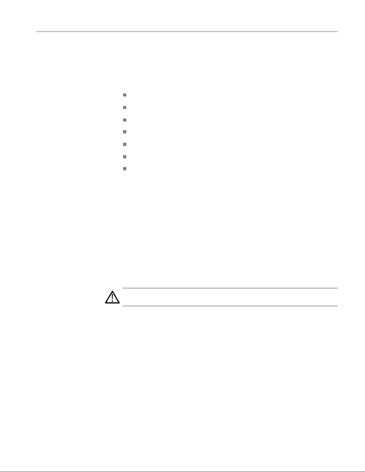
SettingUptheStand
To set up the stand, place the analyzer on a table. Lift the front of the analyzer and
pull out the stand until it is perpendicular to the analyzer.
RSA3303B, RSA3308B, and RSA3408B User Manual 3
Page 16
Installation
Figure 1: Setting up the stand
4 RSA3303B, RSA3308B, and RSA3408B User Manual
Page 17
Applying Power
Installation
Power on the analyzer using the following procedure:
AC Power Requirements
Connecti
ng the Power
Cord
The analyzer
90-250 Volts, without the need for configuration, except the power cord.
The maximum p
The Specifications section contains additional information on power and
environmental requirements. (See page 37, Specifications.)
CAUTION. Use only power cords that are approved for the country of use. Using
non-approved power cords could result in fire or shock hazard.
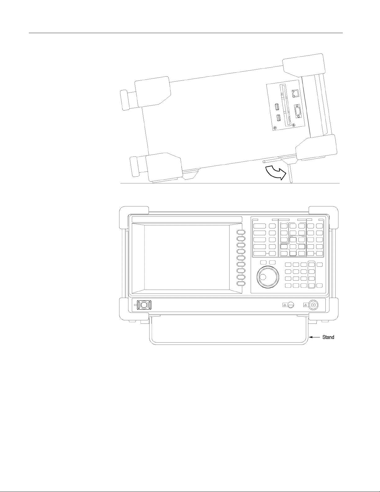
1. Plug the power cord into the AC input on the rear panel.
operates from an AC line frequency of 47-63 Hz, over the range of
ower consumption is 350 W (RSA3300B) or 400 W (RSA3408B).
Figure 2: AC Input (rear panel)
2. Connect the plug of the power cord to a properly grounded outlet.
RSA3303B, RSA3308B, and RSA3408B User Manual 5
Page 18
Installation
TurningontheAnalyzer
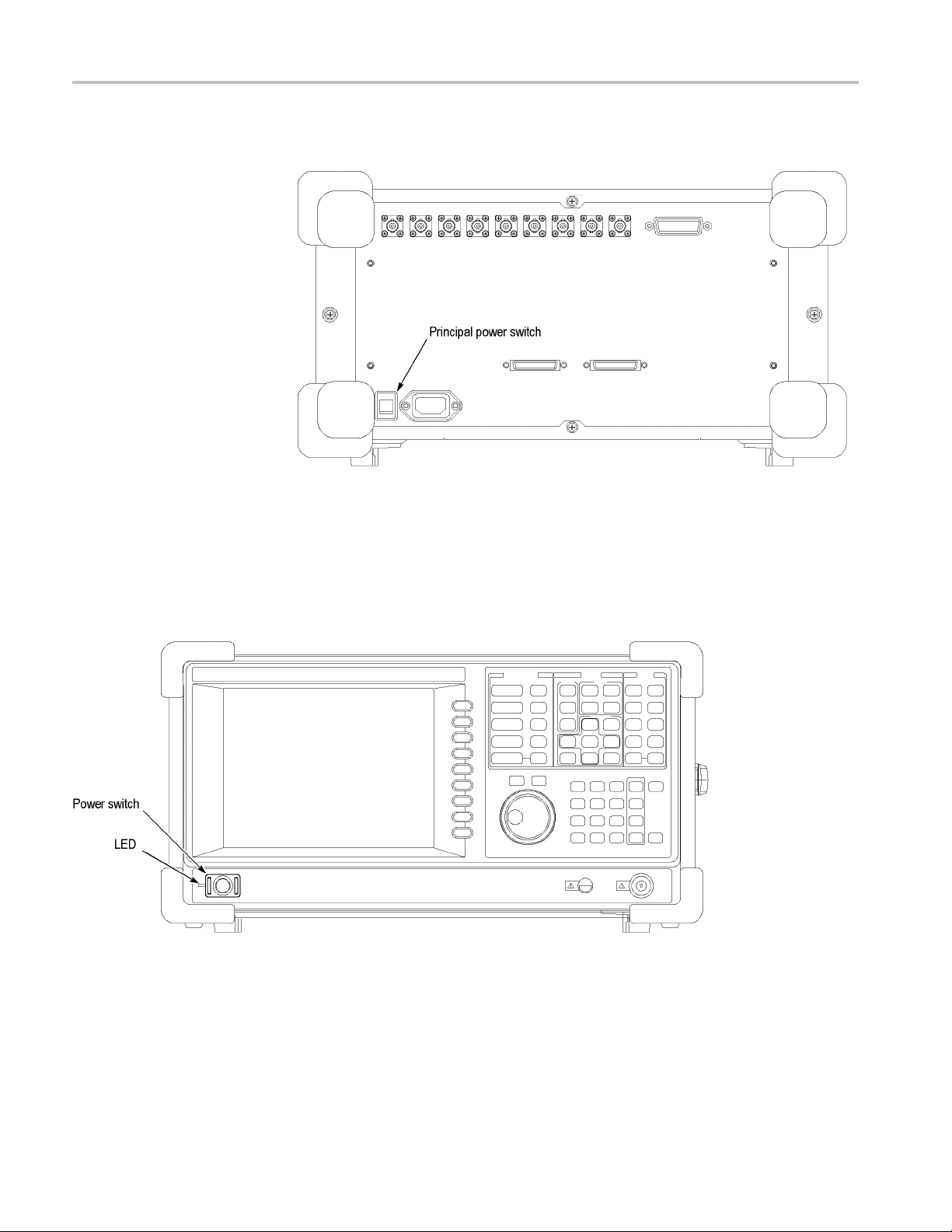
1. Turn on the prin
Figure 3: Principal power switch (rear panel)
When you turn on the principal power switch, a voltage is applied to the
analyzer standby circuit. Make sure the LED next to the power switch on
the front panel lights up in orange.
cipal power switch on the rear panel.
2. Turn on the power switch (ON/STANDBY)onthelowerleftofthefront
panel. The LED next to the power switch changes to green.
Figure 4: Front panel power switch (ON/STANDBY switch)
When you turn on the analyzer, the Windows operating s ystem boots up. After
several minutes, the analyzer application starts up.
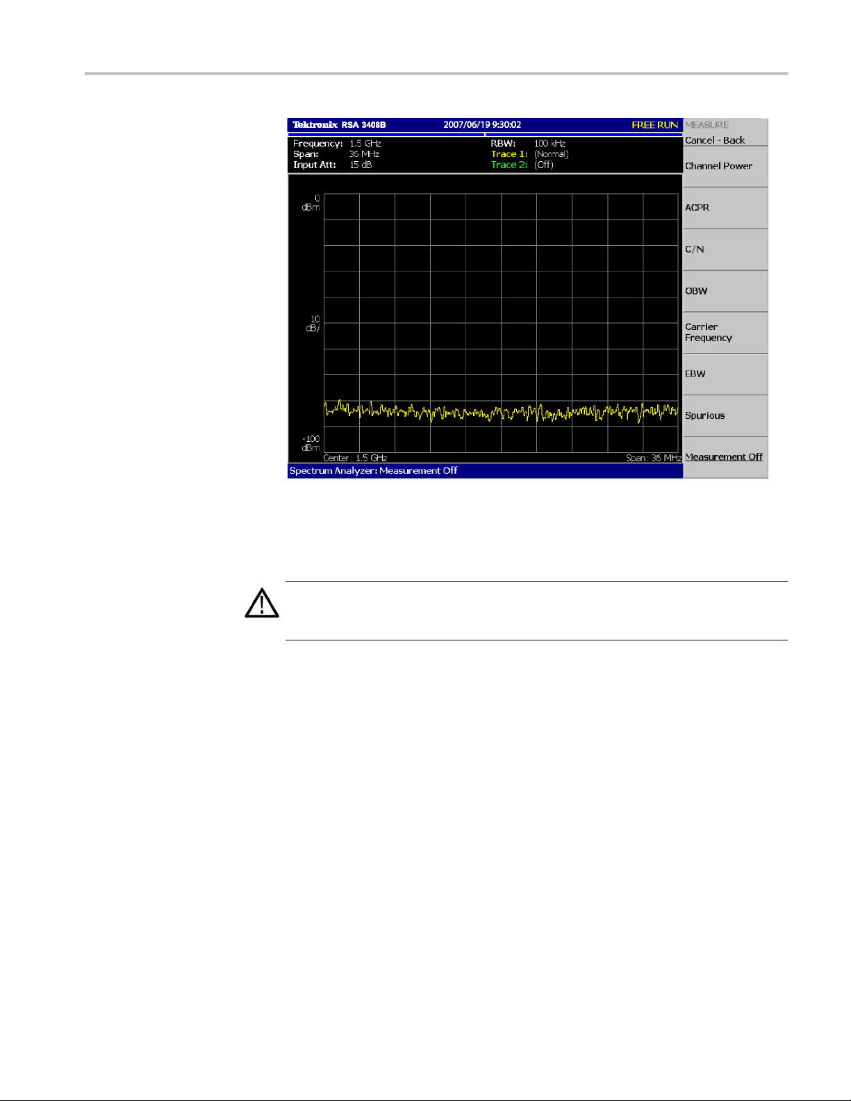
The initial screen appears. (See Figure 5.) The displayed spectrum represents
the noise flooroftheanalyzer.
6 RSA3303B, RSA3308B, and RSA3408B User Manual
Page 19
Installation
Figure 5: Initial screen
If"UNCAL"isdisplayedontopofthescreen, run the gain calibration routine.
(See page 16, Calibrating Gain.)
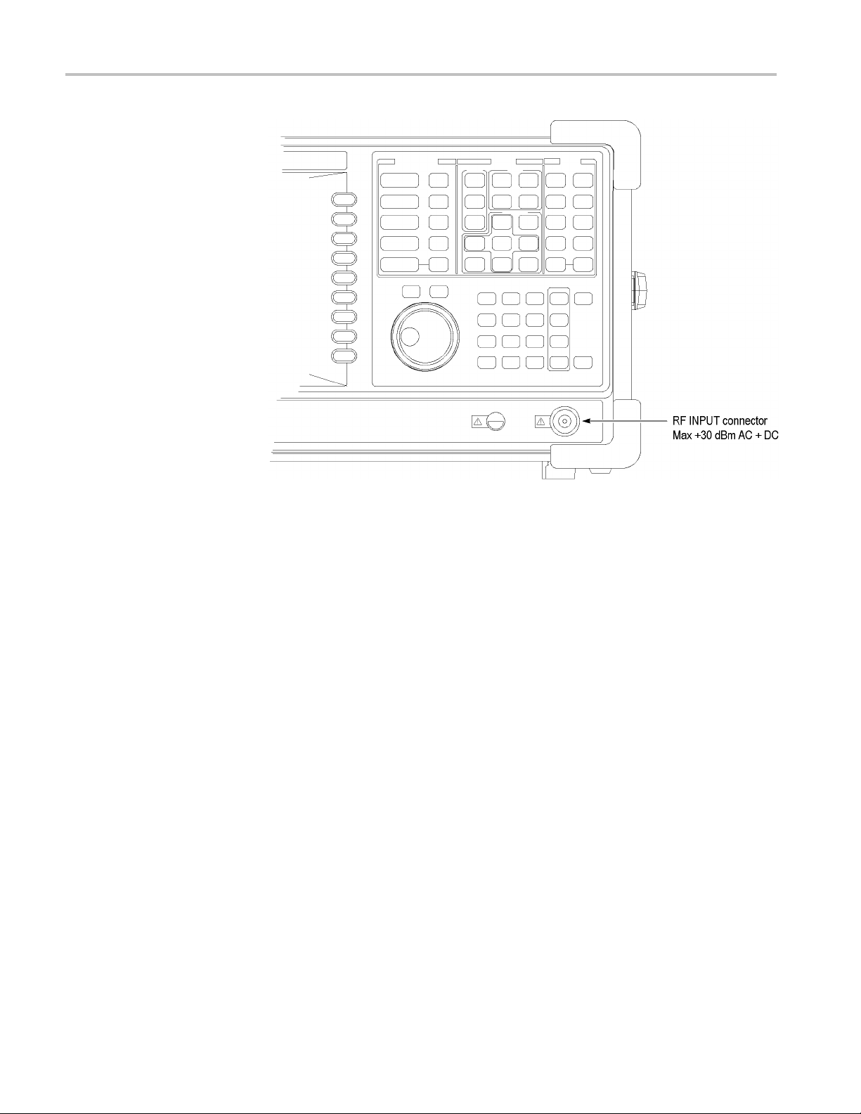
CAUTION. Never apply signals with a combined amplitude greater than +30 dBm
to the RF INPUT connector. Signals greater than +30 dBm can permanently
damage the analyzer. (See Figure 6.)
RSA3303B, RSA3308B, and RSA3408B User Manual 7
Page 20
Installation
Functio
nal Check
Figure 6: RF INPUT connector
The analyzer has a built-in calibration signal source with a frequency of 100 MHz
(RSA3408B) or 50 MHz (RSA3300B) and an amplitude of approximately
-20 dBm.
that your instrument is operating correctly.
1. Turn on
2. Display the spectrum of the calibration signal:
Use the built-in source to perform this quick functional check to verify
the analyzer.
a. Press the S/A key on the front panel and then press the Spectrum
Analyzer side key.
b. Press the PRESET key on the front panel to reset the analyzer.
c. Press the INPUT key on the front panel.
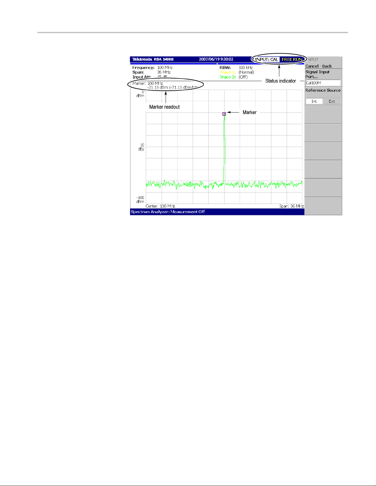
d. Press the Signal Input Port... side key to select Cal100M (RSA3408B)
or Cal (RSA3300B).
The spectrum of the calibration signal appears.
e. Check that "INPUT: CAL" and "FREE RUN" are displayed in the status
indicator at the upper right of the screen. (See Figure 7.)
8 RSA3303B, RSA3308B, and RSA3408B User Manual
Page 21
Installation
Figure 7: Spectrum of the RSA3408B calibration signal (100 MHz, about -20 dBm)
3. Check the center frequency and peak amplitude using the marker:
a. Press the PEAK key on the front panel to place the marker on the peak.
(See Figure 7.)
b. Check the marker readouts on screen. The frequency should be 100 MHz
(RSA3408B) or 50 MHz (RSA3300B) and the amplitude should be
approx
c. Press the MARKER SETUP key o n the front panel and then the Markers
side ke
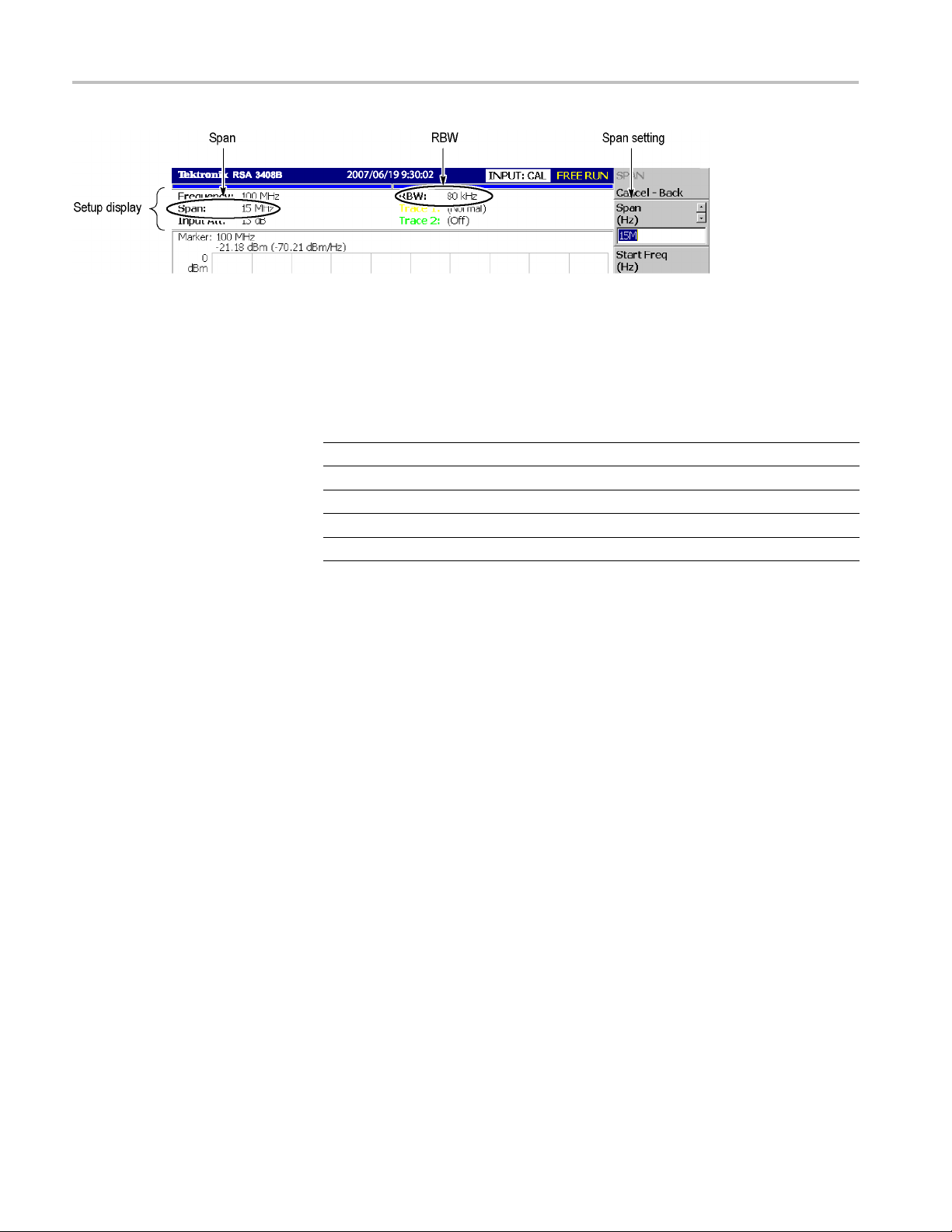
4. Check the RBW (Resolution Bandwidth) while changing the span setting.
a. Press the SPAN key on the front panel.
b. Confirm that the span is 36 MHz (RSA3408B) or 15 MHz (RSA3300B)
and the RBW is 100 kHz (RSA3408B) or 80 kHz (RSA3300B) in the
setup display on the upper part of the screen. (See Figure 8.)
imately -20 dBm.
y to select Off. Check that the marker disappears.
RSA3303B, RSA3308B, and RSA3408B User Manual 9
Page 22
Installation
Figure 8: Setup display
c. Using the general purpose knob, change the span setting as listed below
and check th
at the RBW is displayed correctly.
Table 1: Span and RBW
Span
36 MHz (RSA3408B)
15 MHz 80 kHz
5MHz 20kHz
100 kHz 500 Hz
1 kHz 20 Hz
RBW
100 kHz
d. Using the numeric keypad, set the span back to 36 MHz (RSA3408B) or
15 MHz (RSA3300B). (For example, press 3 → 6 → MHz,inthatorder,
on the keypad.)
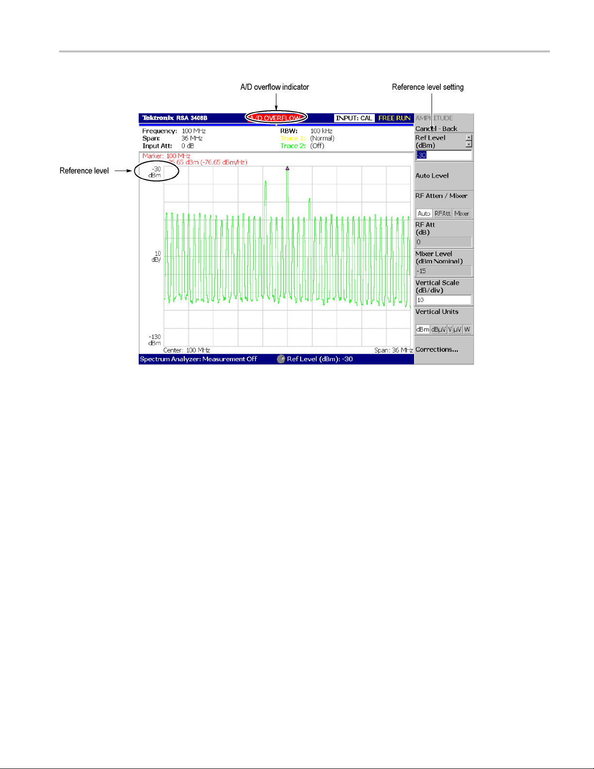
5. Check the reference level:
a. Press the AMPLITUDE keyonthefrontpanel.
b. Make sure that the r eference level is set to 0 dBm with the Ref Level side
key. Check that 0 dBm is displayed on the upper left side of the graticule.
(See Figure 9.)
c. Use the general purpose knob to set the reference level to -30 dBm.
d. Confirm that A/D OVERFLOW is indicated in the red box at the top
center of the screen. Make sure that -30 dBm is displayed on the upper
left side of the graticule and that the spectrum waveform is distorted.
(See Figure 9.)
10 RSA3303B, RSA3308B, and RSA3408B User Manual
Page 23
Installation
Figure 9: Reference level setting and A/D overflow indicator
e. Using the numeric keypad, set the reference level back to 0 dBm. (Press 0
→ ENTER, in that order, on the keypad.)
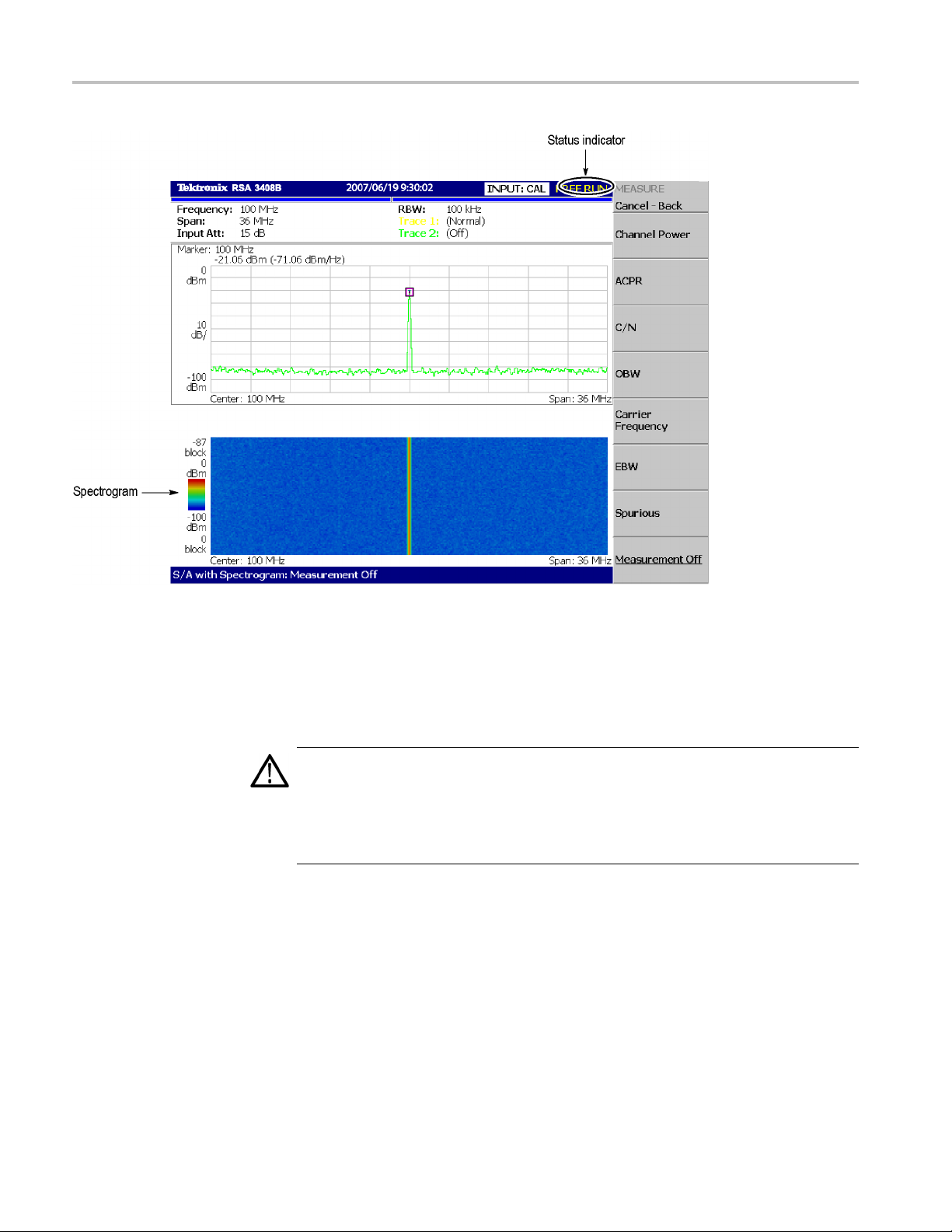
6. Check the spectrogram display:
a. Press t
b. Press the S/A with Spectrogram side key. Check that the spectrogram is
c. Press the RUN/STOP key on the front panel to stop data acquisition.
he S/A keyonthefrontpanel.
yed on the lower side of the screen. (See Figure 10.)
displa
m that the trace display freezes and PAUSE is displayed in the
Confir
status indicator at the top right of the screen.
RSA3303B, RSA3308B, and RSA3408B User Manual 11
Page 24
Installation
Figure 10: Spectrogram display
Powering Off the Analyzer
Turn off the power switch on the front panel.
CAUTION. When you power on or off the analyzer, you must use the front-panel
power switch. Failure to do so may cause the operating system to shut down
improp
When you power on the analyzer again, wait at least 10 seconds after the last
power
When you press the front-panel ON/STANDBY switch, the analyzer starts a
shut
power off. The LED next to the power switch changes to orange. Avoid using the
rear-panel power switch or disconnecting the power cord to power off the analyzer.
To completely remove power to the analyzer, perform the shutdown just described,
and then set the power switch on the rear panel to off.
erly.
off.
down process (including a Windows shutdown) to preserve settings and then
12 RSA3303B, RSA3308B, and RSA3408B User Manual
Page 25

Installation
Restarting the Analyzer
NOTE. Turning o
power supply completely. To turn off the principal power supply, press the
principal power switch o n the rear panel. Turning off the principal power switch
turns off the front-panel LED. When you do not use the analyzer for a long time or
in case of emergency, you should unplug the power cord.
When the ana
analyzer off and on again.
NOTE. When the analyzer operates abnormally, it will not be shut down by
turning off the front-panel power switch alone.
1. Make sure that the front-panel power switch is in the turned-off position.
2. Turn off the principal power switch on the rear panel.
3. Wait at le
4. Turn on the front-panel power switch.
ff the front-panel power switch does not shut down the principal
lyzer operates abnormally, use the following procedure to turn the
ast 10 seconds and then turn on the principal power switch again.
When Sca
n Dis k Appears
When th
eDisplay
Brightness Is Not Even
BackingUpUserFiles
If the analyzer was not shut down properly, Windows Scan Disk may run when you
turn on the analyzer. When the Scan Disk screen appears, wait until the Scan Disk
is completed. If an error is detected, refer to the Windows manual for treatment.
It is a characteristic of the LCD (Liquid Crystal Display) panel to sometimes have
uneven brightness, dead pixels (dots that never turn on) or stuck pixels (dots
that always stay on). This is neither a malfunction nor a defect, and not a cause
epair or exchange.
for r
hould back up your user files on a regular basis as an insurance against
You s
system failures. The Back Up tool is located in the System Tool folder in the
Accessory folder of Windows. Start this tool to select the files and folders to back
up. For more information, use Windows online help.
RSA3303B, RSA3308B, and RSA3408B User Manual 13
Page 26

Installation
les should be backed up more frequently:
is equipped with a LAN Ethernet interface that lets you save data to
Using a LAN
The following fi
Status files (*.sta)
Data files (*. iqt)
Trace files (*.trc)
Correction files (*.cor)
The analyzer
peripheral devices such as other PCs and hard disks.
About Installation of Other Applications
The analyzer incorporates Windows XP as the operating system. Some
combinations of internal measurement applications and external applications
may cause deterioration in the basic performance or conflicts between these
applications.
It is not recommended that you install other applications, including Microsoft
Word, Excel, and Outlook, on the analyzer. If you install an external application,
you do so at your own risk, keeping in mind that it may lower the performance of
the anal
yzer.
14 RSA3303B, RSA3308B, and RSA3408B User Manual
Page 27

Calibration
Calibration
Cal Menu
Perform these
Gain calibration
Center offset calibration
DC offset calibration
IF flatness calibration
Display brightness adjustment
Each item is explained in this section.
Use the CAL key to calibrate the analyzer.
routines to optimize the analyzer performance:
Figure 11: Calibration menu structure
The Cal menu contains the following controls:
Calibrate All. Performs all possible calibration operations.
alibrate Gain. Calibrates the internal gain steps. (See page 16, Calibrating
C
Gain.)
Calibrate Center Offset. This calibration cancels a center offset. (See page 17,
Calibrating Center Offset.)
Calibrate DC Offset. This calibration cancels DC offset in baseband. (See
page 17, Calibrating DC Offset.)
Calibrate IF Flatness. Calibrates the IF (intermediate frequency) flatness. (See
page 18, Calibrating IF Flatness (RSA3408B Only).)
RSA3303B, RSA3308B, and RSA3408B User Manual 15
Page 28

Calibration
Calibrating Gain
Auto Calibrati
calibration operations. The default setting is On.
Service... On
If you want to perform all possible calibration operations together, press the
Calibrate Al
performed automatically any time the analyzer is in an uncal state.
NOTE. When you run the calibration during signal acquisition, the calibration
starts after the acquisition is completed.
The gain calibration calibrates the analyzer’s amplifier gain using the internal
signal gen
the analyzer or when UNCAL (uncalibrated) is displayed during operation.
Allow the
The warm-up period allows electrical performance of the analyzer to stabilize.
During no
±5 °C from the temperature at the last calibration, UNCAL is displayed in the
yellow box at the top of the screen. (See Figure 12.) If this happens, run the
gain calibration.
on. Determines whether to automatically perform all possible
ly used by qualified personnel for repair and calibration.
l side key. When Auto Calibration is set to Yes, they will be
erator. Run this internal calibration routine as required when you boot
analyzer to warm up for 20 minutes before you begin the calibration.
rmal operation, when the ambient temperature changes by more than
Figure 12: UNCAL display
To run the gain calibration, do the following:
1. Press the CAL key on the front panel.
2. Pres
16 RSA3303B, RSA3308B, and RSA3408B User Manual
stheCalibrate Gain side key.
The calibration runs. It takes several seconds to complete the process.
Page 29

Calibration
Calibrating C
enter Offset
When you display a spectrum and no input signal is present, a spurious emission
at the center frequency may appear regardless of frequency settings. The center
offset calib
obvious when you narrow the span, run the calibration.
NOTE. Option 03 only. When you input I and Q signals from the rear panel
connectors, set the IQ input signal level to zero externally.
ration cancels those spurious emissions. If the spurious emission is too
Calibr
ating DC Offset
Figure 1 3: Center offset
To run the center offset calibration, do the following:
1. Press th
2. Press the Calibrate Center Offset side key.
The calibration runs. It takes several seconds to complete the process.
The DC offset calibration cancels DC offset that appears at 0 Hz in the baseband
(RSA3408B: DC to 40 MHz, RSA3300B: DC to 20 MHz). When you change the
ampli
e CAL key on the front panel.
tude setting and the DC offset is too obvious, run the DC offset calibration.
RSA3303B, RSA3308B, and RSA3408B User Manual 17
Page 30

Calibration
Figure 14: DC offset
To run the DC offset calibration, do the following:
1. Press the CAL key on the front panel.
2. Press the Calibrate DC Offset side key.
The calibration runs. It takes several seconds to complete the process.
Calibrating IF Flatness (RSA3408B Only)
The IF flatness calibration adjusts the IF (intermediate frequency) flatness using
the internal signal generator. It optimizes the flatness of gain and phase within
the IF bandwidth automatically. This calibration is recommended in digital
modulation analysis.
To run the IF flatness calibration, do the following:
1. Press the CAL key on the front panel.
2. Press the Calibrate IF Flatness side key.
The cali
bration runs. It takes several seconds to complete the process.
Display Brightness Adjustment
Adjust
the brightness of the display according to your environment.
18 RSA3303B, RSA3308B, and RSA3408B User Manual
Page 31

Calibration
1. Press the SYSTE
Figure 15: System menu
2. Press the Display Brightness side key.
3. Turn the general purpose knob to adjust the brightness. The setting range
is 0 to 100.
M key on the front panel. (See Figure 15.)
Confirming Performance
The electrical characteristics described in Appendix A: Specifications can be
checked
local Tektronix representative.
only by our service personnel. If you need any service, contact your
RSA3303B, RSA3308B, and RSA3408B User Manual 19
Page 32

Calibration
20 RSA3303B, RSA3308B, and RSA3408B User Manual
Page 33

Functional Overview
This section describes the controls, connectors, display, and menu operation.
Interface Map
Controls and Connectors
s
The following Figures show the controls and connectors on the front, the side,
and the rear panels.
e 16: Front panel
Figur
RSA3303B, RSA3308B, and RSA3408B User Manual 21
Page 34

Functional Overview
1. Display. Size:
colors maximum
2. Side Keys. Select menu items associated with menu keys.
3. Menu keys. Select menus.
4. Keypad. Enters alpha and numeric characters.
5. RF input connector. Connects an input signal. N-type connector, Input
impedance: 50 Ω. Maximum capacity of non-breakdown input: 30 dBm.
6. Preamplifier power source. Provides power source for a preamplifier
(optional accessory). (See Table 30 on page 57.)
7. General purpose knob. Changes a value.
8. Up/Down keys. Increase or decrease a value.
9. Power switch (ON/STANDBY). (See page 6, TurningontheAnalyzer.)
10. LED. Green on operating, orange on standby.
CAUTION. Applying a signal of more than +3
21.3 cm (8.4 inch) Resolution: 800 X 600 dots Color: 256
0 dBm may damage the instrument.
Figure 17: Rear panel
22 RSA3303B, RSA3308B, and RSA3408B User Manual
Page 35

Functional Overview
1. REF IN/OUT conn
input/output. (See Table 10 on page 42.)
2. I+/I- INPUT co
signal differential input. When using one connector as a single-ended input,
terminate the other end in 50 Ω.
3. Q+/Q- INPUT connector (Option 03 only).50Ω BNC connector for Q
signal differential input. When using one connector as a single-ended input,
terminate the other end in 50 Ω.
4. TRIG IN/OUT connector. 50 Ω BNC connector for trigger signal
input/output. (See Table 16 on page 48.)
5. 421 MHz IF OUT connector. (RSA3408B only) 50 Ω BNC connector for
421 MHz IF (Intermediate Frequency) output.
6. GPIB connector. Used to control the analyzer from an external controller.
Refer to the programmer manual for GPIB control.
7. DIGITAL IQ OUT (RSA3408B Option 05 only). MDR (3M) 50-pin
connectors for generating I and Q data after A/D conversion to store and
analyze o n an external PC. (See Table 30 on page 57.)
8. AC input. Connect AC power cable.
ector. 50 Ω BNC connector for reference signal
nnector (Option 03 only). 50 Ω BNC connector for I
9. PRINCIPAL POWER SWITCH. When this switch is on, the internal
standby circuit is energized. (See page 6, Turning on the Analyzer.)
RSA3303B, RSA3308B, and RSA3408B User Manual 23
Page 36

Functional Overview
Figure 18: Side panel
1. Indicator. Indicates whether the disk drive is active.
CAUTION. When this indicator is lit, you must not remove the disk from the
disk drive. If you do so, the data stored on the medium may be destroyed or an
error m
2. Disk drive. Saves and loads data and settings. A 3.5-inch 2HD (1.44MB) or
3. LAN Ethernet connector. 10/100BASE-T connector. Connects this
4. VGA output connector. Sends the display of this instrument to another
5. USB connector. Connect a mouse, a keyboard and a printer that meets USB
ay occur.
2DD (7
instr
moni
spec
20KB) disk formatted for MS-DOS can be used.
ument to a network.
tor. 15 pin D-sub connector (female)
ifications.
24 RSA3303B, RSA3308B, and RSA3408B User Manual
Page 37

Functional Overview
Using a Mouse and
Keyboard
You can operate
the analyzer using the standard accessory mouse and keyboard
instead of the side keys and the front panel keypad.
The mouse and k
eyboard operations are as follows:
Click the menu item instead of pressing the side keys.
If the menu item has arrow buttons, click them to select the value.
Figure 19: Operation with m ouse and keyboard
Table 2: Key functions of the keyboard
Key Purpose Function
Numeric keys Numeric input Enter a numeric value in a numeric
input field.
Left/Right arrow keys Caret move
Home
End
Backspace Alphanumeric input
Delete Alphanumeric input
ESC
ENTER Alphanumeric input
K or k key Alphanumeric input
M key Alphanumeric input
Gorgkey
m key Alphanumeric input
Caret move Moves the caret to the beginning of
Caret move Moves the caret to the end of an input
Alphanumeric input Aborts a numeric entry and restores
Alphanumeric input
Moves the caret in an alpha or
numeric input field.
an input field.
field.
Deletes the character before the
caret.
Deletes the character after the caret.
the original value.
Accepts a value in the input field.
3
Kilo (10
entry of the value.
Mega (10
complete entry of the v alue.
Giga (109). Press ENTER to complete
entry of the value.
milli (10
entry of the value.
). Press ENTER to complete
6
). Press ENTER to
-3
). Press ENTER to complete
RSA3303B, RSA3308B, and RSA3408B User Manual 25
Page 38

Functional Overview
Table 2: Key functions of the keyboard (cont.)
Key Purpose Function
U or u key Alphanumeric input
N or n key Alphanumeric input
micro (10
complete entry of the v alue.
nano (10
complete entry of the v alue.
-6
). Press ENTER to
-9
). Press ENTER to
Display Screen
The following Figure shows the elements of the display screen.
Figure 20: Display screen configuration (RSA3408B shown)
26 RSA3303B, RSA3308B, and RSA3408B User Manual
Page 39

Functional Overview
Status Display
1. Setup display a
rea. Displays the current hardware value. (See page 29,
Setup Display.)
2. Progress bar.
Indicates the progress of the acquisition cycle on the left bar
and the measurement cycle on the right bar. The progress fills up in blue
from left to right.
3. Date/Time display area. Shows the current date and time.
4. Status displ
ay area. Shows the trigger status. (See page 27, Status Display.)
5. Side menu display area. When you press a menu key on the front panel, the
menu associ
ated with that key is displayed.
6. Menu setting display area. Displays the last setting of the menu item that
can be set wi
th the general purpose knob.
7. View. The View window displays the waveform or the measurement results.
Multiple v
iews can be displayed on one display screen, depending on the
measurement mode.
8. Measurem
ent function display area. Displays the measurement function
currently in use (the settings of the Mode and Measure menus).
The status display area in the upper right side of the screen shows the instrument
status a
s listed in the table below. (See Figure 21.)
Figure 21: Status display (RSA3408B shown)
Table 3: Status display
Item Description
ARM
READY
TRIG’D
The pre-trigger portion of the acquisition record is filling. A trigger event
occurring during this state will not be recognized.
Pre-trigger data has been acquired, and the instrument is waiting for a
trigger event.
Pre-trigger data has been acquired, and a trigger event has been
detected. The instrument is now acquiring post-trigger data.
RSA3303B, RSA3308B, and RSA3408B User Manual 27
Page 40

Functional Overview
Table 3: Status display (cont.)
Item Description
FREE RUN
PAUSE The user has temporarily stopped acquisition/measurement cycling.
The instrument acquires and measures without waiting for a trigger event.
The acquired data is stored in the data memory from address zero in order of
acquisition. When you set a trigger condition, the acquired data is stored in the
pre-trigge
r region until the trigger event occurs. Thereafter, i t is stored in the
post-trigger region. (See Figure 22.)
Figure 22: Pre- and post-trigger regions
Front Pan el Key Lock
When controlling this instrument through GPIB, you can disable all the keys on
the front panel except the power switch using the :SYSTEM:KLOCK command.
At this time, the message "PANEL LOCK" is displayed on the top side key.
(See Figure 23.)
Figure 2 3: Key lock display
28 RSA3303B, RSA3308B, and RSA3408B User Manual
Page 41

Functional Overview
Setup Display
To cancel the ke
y lock, the following two methods can be used:
Use the :SYSTEM:KLOCK command to cancel.
Turn off the power and then on.
Refer to the programmer manual for information about the GPIB commands.
The setup display area in the upper part of the screen shows the analyzer hardware
settings. (See Figure 24.) The contents differ depending on the measurement
mode: spectrum analysis (S/A), modulation analysis (Demod), or time analysis
(Time), as shown in the table below.
Figure 24: Setup display (RSA3408B shown)
Table 4: S
etup display
Item Descript
Frequency Indicates the center
frequenc
Span
Input Att Indicates the attenuation
RBW
NBW
Trace 1 and 2 Indicates the Trace 1 and 2
Indicates the span.
of an inpu
enters the internal mixer.
Indicates RBW (Resolution
Bandwidth) for compatibility
with swe
analyzers.
Indicates NBW (Noise
Bandwidth) instead of RBW
when FF
does not go through RBW
process.
trace type.
ion
y.
t signal before it
pt spectrum
T-processed data
Mode
All
S/A
RSA3303B, RSA3308B, and RSA3408B User Manual 29
Page 42

Functional Overview
Menu Operations
Table 4: Setup display (cont.)
Item Description Mode
Spectrum Length Indicates time length of a
1024-point FFT frame. It is
determined by the span.
Spectrum Interval
Acquisition Length Indicates time to acquire a
Indicates time interval
between FFT frames.
block of data. It can be set
in the Timing menu.
Real Time S/A
Demod and Time
This section describes basic operations of the analyzer menus and how to select
menu items
and input numeric values.
Menu Item Information
Up to nine soft keys can be displayed down the right side of the screen. (See
Figure 25.) Cancel - Back is always displayed at the top, and the other eight
keys sel
ect menu items.
30 RSA3303B, RSA3308B, and RSA3408B User Manual
Page 43

Functional Overview
Figure 25: Examples of menu item display
NOTE. When the setting is prohibited or is not available, the item is displayed
in gray.
RSA3303B, RSA3308B, and RSA3408B User Manual 31
Page 44

Functional Overview
Menu Item Types
The different t
ypes of menu items are shown below.
Table 5: Menu item types
Numeric entry
The current value of parameter is displayed. To change the
value, press the associated side key and use the general
purpose knob,
Tog gle
You can switch selection items by pressing the associated side
key.
Function exe
The function indicated on the label is executed by pressing
associated side key. In this example, the “Channel Power”
measurement
Move to sub-m
If the label is followed by “...”, you can move to a lower-level
menu by pressing the associated side key.
Move betwee
When the number of menu items is greater than seven, this
menu appears. To move to the next page, press the associated
side key. If
page.
Invalid
Menu items without labels do not cause any action.
up/down keys, or the keypad.
cution
is performed.
enu
n pages
you are on the last page, you will return to the first
Numeric I
nput
An example numeric input field is shown below. In this type of field, you can
change the numeric value by turning the general purpose knob, by pressing the
up/down (▲▼) keys, or by entering a value using the keypad.
Figure 26: Numeric setting menu
32 RSA3303B, RSA3308B, and RSA3408B User Manual
Page 45

Functional Overview
Changing Value
1. Press the side key to set a numeric value. For example, press
FREQUENCY/CHANNEL→ Center Freq to set a center frequency.
The m enu item changes to the display as shown below.
Figure 27: Changing value with the knob
2. Turn the general purpose knob to increase or decrease the value.
You c a n als o u
value, respectively.
Using the General Purpose Knob or the Up and Down keys.
se the up and down (▲▼) keys to increase or decrease a setting
The up and
the step size (the amount per click by which the general purpose knob changes a
setting value or the amount per press for the up and down keys) as follows:
For the general purpose knob, the step s ize is determined internally. You
can not change the step size.
For the up and down keys, the step size is set with the Step Size side key.
(See page 34, Changing the Step Size.)
The changed value is immediately reflected on the analyzer settings and displays.
Entering a Value Using the Keypad. You can enter values using the front panel
keypad. (See Figure 29.)
down keys have the same functions as the general purpose knob except
RSA3303B, RSA3308B, and RSA3408B User Manual 33
Page 46

Functional Overview
1. Press the side k
FREQUENCY/CHANNEL → Center Freq to set a center frequency.
The menu item c
Figure 28: Changing value with the keypad
2. Press the keys required to enter the desired numeric value. For example, to
enter the frequency 123.45 MHz, press 123.45MHz.
To delete an entered number, press the BKSP (Backspace) key.
ey for setting a numeric value. For example, press
hanges to the display shown below.
Figure 2 9: Numeric keypad
3. Confirm the input by pressing the unit key or ENTER key. The confirmed
value is immediately reflected to the analyzer settings and display.
Press the Cancel - Back side key to cancel the change.
Changing the Step Size
34 RSA3303B, RSA3308B, and RSA3408B User Manual
When using the up and down (▲▼) keys to increase or decrease a setting value,
you can
changes the setting value) with the Step Size.
In the
displayed frequency set value changes by 100 kHz step for each press of the
up or down key.
change the step size (the amount per press b y which the up or down key
example below, the step size for the start frequency is set to 100 kHz; the
Page 47

Functional Overview
Figure 30: Changing the step size for the center frequency
Step Size for Center Frequency. The step size is set with the Step Size side
key. The center frequency step size can be also set with two side keys in the
Frequency/Channel menu. (See Figure 31.)
Center Freq Step Same As C.F. Useful for quickly locating harmonics of a
signal seen at the center frequency.
Center Freq Step Same As Span. Useful for quickly analyzing a larger
frequency area without overlapping span windows.
Figure 31: Changing the step size for the center frequency
RSA3303B, RSA3308B, and RSA3408B User Manual 35
Page 48

Functional Overview
36 RSA3303B, RSA3308B, and RSA3408B User Manual
Page 49

Appendix A: Specifications
This appendix lists the electrical, physical, and environmental characteristics
of the RSA3408B and RSA3300B analyzers, and it specifies the p erformance
requirement
RSA3408B and RSA3300B analyzers, except where noted.
s for those characteristics. Characteristics apply to both the
Unless other
features apply to the analyzer after a 20 minute warm-up period (within the
environmental limits) and after all calibration procedures have been carried out.
wise stated, the following tables of electrical characteristics and
RSA3303B, RSA3308B, and RSA3408B User Manual 37
Page 50

Appendix A: Specifications
Electrical Ch
aracteristics
Table 6: Frequency
Characterist
Measurement f
Reference fre
ics
requency
RSA3408B Fre
RSA3300B Frequency range Baseband: DC to 20 MHz
Center frequency setting resolution
RSA3408B Frequency marker readout accuracy Baseband: ±(RE × MF + 0.001 × Span + 0.2) Hz
RSA3300B Fre
At specified frequency Baseband, Frequency = 10 MHz, Span = 1 MHz
Residual FM (T
Span accuracy
RBW filter band
quency range
quency marker readout accuracy
ypical)
width accuracy
quency
Description
Overall: DC t
Baseband: DC to 40 MHz
RF1: 40 MHz to 3.5 GHz
RF2: 3.5 GHz to
RF3: 5 GHz to 8 GHz
RF: 15 MHz to 3 GHz (RSA3303B)
RF1: 15 MHz to 3
RF2: 3.5 GHz to 6.5 GHz (RS A3308B)
RF3: 5 GHz to 8 GHz (RSA3308B)
0.1 Hz
RF1to3: ±(RE×
RE: Reference frequency error; MF: Marker frequency [Hz]
The first term of these formula shows the frequency uncertainty due to the
reference fre
the limited bin number. Because more than 500 bins are available in the
frequency display, 0.5 bin uncertainty corresponds to 0.001. The third
term shows th
Baseband: ±(
RF, RF1 to 3: ±(RE × MF + 0.001 × Span + 2) Hz
RE: Reference frequency error; MF: Marker frequency [Hz]
Marker: ±1 kHz
RF/RF1, Frequency = 2 GHz, Span = 1 MHz
Marker: ±1.2 kHz; Carrier frequency measurement: ±210 Hz
RF2, Frequenc
Marker: ±1.5 kHz; Carrier frequency measurement: ±510 kHz
RF3, Frequency = 7 GHz, Span = 1 MHz (RSA3308B only)
Marker: ±1.7 k
2Hzp-p
±1 bin
0.1% against n
o8GHz
6.5 GHz
.5 GHz (RSA3308B)
MF+0.001×Span+2)Hz
quency error. The second term shows the uncertainty due to
e residual FM.
RE × MF + 0.001 × Span + 0.2) Hz
; Carrier frequency measurement: ±1.2 kHz
y = 5 GHz, Span = 1 MHz (RSA3308B only)
Hz; Carrier frequency measurement: ±710 kHz
oise bandwidth
38 RSA3303B, RSA3308B, and RSA3408B User Manual
Page 51

Appendix A: Specifications
Table 6: Frequency (cont.)
Characteristics Description
Aging per day
Aging per year
1×10
1×10
-9
(after 30 days of operation)
-7
(after 30 days of operation)
Temperature drift 1 × 10⁻⁷(10to40°C)
Total frequency error 2 × 10⁻⁷(within one year after calibration)
Reference output level
>0 dBm
External reference input 10 MHz, -10 to +6 dBm. Spurious level must be <-80 dBc within 100 kHz
offset.
Table 7: RSA3300B Spectrum purity
Characteristics Description
Spectrum purity (Frequency = 1500 MHz)
Carrier offset = 10 kHz, span = 100 kHz -100 dBc/Hz
Carrier offset = 100 kHz, span = 1 MHz -105 dBc/Hz
Carrier offset = 1 MHz, span = 5 MHz -125 dBc/Hz
Table 8: RSA3300B Noise sideband
Characteristics
Frequency = 1000 MHz
Frequency = 2000 MHz
Frequency = 6000 MHz
(RSA3308B only)
Description
Noise sideband
-100 dBc/Hz
-105 dBc/Hz
-105 dBc/Hz
-105 dBc/Hz
-112 dBc/Hz
-132 dBc/Hz
-135 dBc/Hz
-135 dBc/Hz
-96 dBc/Hz
-104 dBc/Hz
-105 dBc/Hz
-105 dBc/Hz
-112 dBc/Hz
-132 dBc/Hz
-135 dBc/Hz
-135 dBc/Hz
-87 dBc/Hz
-104 dBc/Hz
-105 dBc/Hz
-105 dBc/Hz
-112 dBc/Hz
-128 dBc/Hz
-130 dBc/Hz
-130 dBc/Hz
Offset
1kHz
10 kHz
20 kHz
30 kHz
100 kHz
1MHz
5MHz
7MHz
1kHz
10 kHz
20 kHz
30 kHz
100 kHz
1MHz
5MHz
7MHz
1kHz
10 kHz
20 kHz
30 kHz
100 kHz
1MHz
5MHz
7MHz
RSA3303B, RSA3308B, and RSA3408B User Manual 39
Page 52

Appendix A: Specifications
Table 8: RSA3300B Noise sideband (cont.)
Characteristics
Frequency = 1000 MHz, Typical
Frequency = 2000 MHz, Typical
Frequency = 6000 MHz, Typical
(RSA3308B only)
Description
Noise sideband
-103 dBc/Hz
-108 dBc/Hz
-108 dBc/Hz
-108 dBc/Hz
-115 dBc/Hz
-135 dBc/Hz
-138 dBc/Hz
-138 dBc/Hz
-99 dBc/Hz
-107 dBc/Hz
-108 dBc/Hz
-108 dBc/Hz
-115 dBc/Hz
-135 dBc/Hz
-138 dBc/Hz
-138 dBc/Hz
-90 dBc/Hz
-107 dBc/Hz
-108 dBc/Hz
-108 dBc/Hz
-115 dBc/Hz
-131 dBc/Hz
-133 dBc/Hz
-133 dBc/Hz
Offset
1kHz
10 kHz
20 kHz
30 kHz
100 kHz
1MHz
5MHz
7MHz
1kHz
10 kHz
20 kHz
30 kHz
100 kHz
1MHz
5MHz
7MHz
1kHz
10 kHz
20 kHz
30 kHz
100 kHz
1MHz
5MHz
7MHz
Table 9: RSA340
Characteristi
Frequency = 1000 MHz
8B Noise sideband
cs
Description
Noise sideband
-105 dBc/Hz
-110 dBc/Hz
-110 dBc/Hz
-110 dBc/Hz
-112 dBc/Hz
-132 dBc/Hz
-138 dBc/Hz
-138 dBc/Hz
-138 dBc/Hz
Offset
1kHz
10 kHz
20 kHz
30 kHz
100 kHz
1MHz
5MHz
7MHz
10 MHz
40 RSA3303B, RSA3308B, and RSA3408B User Manual
Page 53

Table 9: RSA3408B Noise sideband (cont.)
Characteristics
Frequency = 2000 MHz
Frequency = 6000 MHz
Frequency = 1000 MHz, Typ ical
Frequency = 2000 MHz, Typ ical
Frequency = 6000 MHz, Typ ical
Description
Noise sideband
-103 dBc/Hz
-109 dBc/Hz
-109 dBc/Hz
-109 dBc/Hz
-112 dBc/Hz
-132 dBc/Hz
-138 dBc/Hz
-138 dBc/Hz
-138 dBc/Hz
-97 dBc/Hz
-106 dBc/Hz
-106 dBc/Hz
-106 dBc/Hz
-111 d Bc /H z
-132 dBc/Hz
-137 dBc/Hz
-137 dBc/Hz
-137 dBc/Hz
-107 dBc/Hz
-112 dBc/Hz
-112 dBc/Hz
-112 dBc/Hz
-115 dBc/Hz
-135 dBc/Hz
-140 dBc/Hz
-140 dBc/Hz
-140 dBc/Hz
-105 dBc/Hz
-111 d Bc /H z
-111 d Bc /H z
-111 d Bc /H z
-115 dBc/Hz
-135 dBc/Hz
-140 dBc/Hz
-140 dBc/Hz
-140 dBc/Hz
-99 dBc/Hz
-108 dBc/Hz
-108 dBc/Hz
-108 dBc/Hz
-113 dBc/Hz
-134 dBc/Hz
-139 dBc/Hz
-139 dBc/Hz
-139 dBc/Hz
Appendix A: Specifications
Offset
1kHz
10 kHz
20 kHz
30 kHz
100 kHz
1MHz
5MHz
7MHz
10 MHz
1kHz
10 kHz
20 kHz
30 kHz
100 kHz
1MHz
5MHz
7MHz
10 MHz
1kHz
10 kHz
20 kHz
30 kHz
100 kHz
1MHz
5MHz
7MHz
10 MHz
1kHz
10 kHz
20 kHz
30 kHz
100 kHz
1MHz
5MHz
7MHz
10 MHz
1kHz
10 kHz
20 kHz
30 kHz
100 kHz
1MHz
5MHz
7MHz
10 MHz
RSA3303B, RSA3308B, and RSA3408B User Manual 41
Page 54

Appendix A: Specifications
Table 10: Input
Characteristics Description
Signal input
Input connect
Input impedan
VSWR <1.4 (2.5 GHz, RF attenuation ≥10 dB)
Typ ical
Maximum input level
Maximum DC v oltage ±0.2 V (RF (RSA3303B), RF1 to 3)
Maximum input power
Input atten
RF/Baseban
I/Q attenua
Input atten
RF/Baseban
or
ce
uator (RSA3408B)
d attenuator
tor (Option 03)
uator (RSA3300B)
d attenuator
N type (RF and baseband input); BNC type (Option 03 IQ input)
50 Ω
<1.8 (7.5 GHz, RF attenuation ≥10 dB (RSA3308B and RSA3408B only))
<1.4 (300 kHz to 40 MHz, RF attenuation ≥10 dB)
<1.3 (40 MHz to
<1.4 (3 GHz to 8 GHz, RF attenuation ≥10 dB (RSA3308B and RSA3408B
only))
±5 V (Baseband)
±5 V (Option 0
+30 dBm (RF (R
0to55dB(5d
0to35dB(5d
0to50dB(2d
3 GHz, RF attenuation ≥10 dB)
3 IQ input)
SA3303B), RF1 to 3, RF attenuation ≥10 dB)
B step)
B step)
B step in RF/RF1/Baseband; 10 dB step in RF2/RF3)
42 RSA3303B, RSA3308B, and RSA3408B User Manual
Page 55

Table 10: Input (cont.)
Characteristics Description
I/Q attenuator (Option 03) 0 to 30 dB (10 dB step)
Table 11: RSA3408B Amplitude
Characteristics Description
Reference level
Reference level setting range Baseband: -30 to +20 dBm (5 dB step)
RF: -50 to +3
Option 03 IQ input: -10 to +20 dBm (5 dB step)
Accuracy (-10 to -50 dBm) ±0.2 dB (at 100 MHz, 10 dB attenuation, 20 to 30 °C)
Frequency response (RF attenuation ≥10 dB)
at 20 to 30 °C ±0.5 dB (100 kHz to 40 MHz)
±1.2 dB (40 MHz to 3.5 GHz)
±1.7 dB (3.5
±1.7 dB (5 GHz to 8 GHz)
Typ ical
at 10 to 40 °C ±0.7 dB (100 kHz to 40 MHz)
Absolute amplitude accuracy at calibration point (20
to 30 °C)
Input attenuator setting uncertainty
Level linearity in display range
±0.3 dB (100 kHz to 40 MHz)
±0.5 dB (40 MHz to 3.5 GHz)
±1.0 dB (3.5
±1.0 dB (5 GHz to 8 GHz)
±1.5 dB (40 MHz to 3.5 GHz)
±2.0 dB (3.5
±2.0 dB (5 GHz to 8 GHz)
Baseband: ±0.3 dB (at 25 MHz, -10 dBm signal)
RF: ±0.5 dB (at 100 MHz, -20 dBm signal, 0 dB attenuation)
±0.2 dB (at 100 MHz)
±0.2 dB (0 to -50 dBfs); ±0.12 dB (0 to -50 dBfs, Typical)
0 dBm (1 dB step)
GHz to 6.5 GHz)
GHz to 6.5 GHz)
GHz to 6.5 GHz)
Appendix A: Specifications
RSA3303B, RSA3308B, and RSA3408B User Manual 43
Page 56

Appendix A: Specifications
Table 12: RSA33
Characteristics Description
Reference level
Reference level setting range Baseband: -30 to +20 dBm (2 dB step)
Accuracy (-10 to -50 dBm) ±0.2 dB (at 50 MHz, 10 dB attenuation, 20 to 30 °C)
Frequency response (RF attenuation ≥10 dB)
at 20 to 30 °C ±0.5 dB (Baseband)
Typ ical
at 10 to 40 °C ±0.7 dB (Baseband)
Absolute amplitude accuracy at calibration point (0 dB
attenuation,
Input attenuator setting uncertainty
Level linearity in display range
Channel power measurement accuracy for W-CDMA
signal at 20 to
00B A mplitude
20 to 30 °C)
30 °C
RF/RF1: -51 to +30 dBm (1 dB step)
RF2/RF3 (RSA3
Option 03 IQ input: -10 to +20 dBm (10 dB step)
±1.2 dB (RF/RF1)
±1.7 dB (RF2, R
±1.7 dB (RF3, RSA3308B only)
±0.3 dB (100 kHz to 20 MHz)
±0.5dB(10MHzto3GHz)
±0.5 dB (10 MHz
±1.0 dB (3.5 GHz to 6.5 GHz, RSA3308B only)
±1.0 dB (5 GHz to 8 GHz, RSA3308B only)
±1.5 dB (RF/RF1
±2.0 dB (RF2, RSA3308B only)
±2.0 dB (RF3, RSA3308B only)
±0.3 dB (Baseband at 10 MHz, -10 dBm signal)
±0.5 dB (at 50 MH
±0.5 dB (at 50 MH
±0.2 dB (0 to -4
±0.2 dB (0 to -50 dBfs), Typical)
±0.12dB(0to-50dBfs,Typical)
±0.6 dB (Signal frequency: 1900 to 2200 MHz; Signal power: +10 to
-30 dBm; RF att
span)
308B only): -50 to +30 dB m (1 dB step)
SA3308B only)
to 3.5 GHz, RSA3308B only)
)
z, -20 dBm signal)
z)
0dBfs)
enuation: 0 to 20 dB; After Auto Level operation at 10 MHz
Table 13: Spurious response
Characteristics Description
1 dB compression input
nd
RSA3408B: 2
input mixer)
RSA3300B: 2ndharmonic distortion (-30 dBm tone at
input mixer)
RSA3408B: 3rdorder intermodulation distortion (Reference level = +5 dBm , RF attenuation adjusted optimally, Total signal power =
-7 dBm)
harmonic distortion (-30 dBm tone at
+2 dBm (RF attenuation = 0 dB, 2 GHz)
-65 dBc (10 MHz to 1400 MHz)
-70 dBc (1400 MHz to 1750 MHz)
-56 dBc (10 MHz to 1500 MHz)
-56 dBc (10 MHz to 1750 MHz, RSA3308B only)
44 RSA3303B, RSA3308B, and RSA3408B User Manual
Page 57

Appendix A: Specifications
Table 13: Spurious response (cont.)
Characteristics Description
Center frequency = 2 GHz
100 MHz to 3 GHz
3GHzto8GHz
RSA3300B: 3rdorder intermodulation distortion (Reference level = +5 dBm , RF attenuation = Adjusted, Total signal power = -7 dBm)
Center frequency = 2 GHz
100 MHz to 3 GHz
3 GHz to 8 GHz (RSA3308B only)
Displayed average noise level
RSA3300B: ACLR (3GPP down link, test model 1,
16 ch)
Typical
Local feed-through to input connector (Typical) -40 dBm (local frequency 4.2 to 5 GHz)
RSA3408B Image Suppression (Typical)
1stIF
2ndand 3rdIF
RSA3300B Image Suppression (Typical)
1stIF
2ndand 3rdIF
Alias suppression (Typical) 65 dB (DC to 40 MHz, RSA3408B)
RSA3408B Residual response (Reference level = -30 dBm, RBW = 100 kHz)
-78 dBc
-75 dBc
-72 dBc
-74 dBc
-74 dBc
-72 dBc
-144 dBm/Hz (1 kHz to 10 kHz, RSA 3300B only)
-144 dBm/Hz (100 Hz to 10 kHz, RSA3408B)
-151 dBm/Hz (10 kHz to 10 MHz)
-151 dBm/Hz (10 MHz to 100 MHz)
-150 dBm/Hz (100 MHz to 1 GHz)
-150 dBm/Hz (1 GHz to 2 GHz)
-150 dBm/Hz (2 GHz to 3 GHz)
-142 dBm/Hz (3 GHz to 5 GHz)
-142 dBm/Hz (5 GHz to 8 GHz)
60 dB (5 MHz o ffset)
63 dB (10 MHz offset)
66 dB (5 MHz o ffset)
70 dB (10 MHz offset)
-55 dBm (local frequency 5 to 6 GHz)
-60 dBm (local frequency 6 to 7 GHz)
-60 dBm (local frequency 7 to 7.7 GHz, RSA3308B and RS A3408B only)
75 dB (40 MHz to 3.5 GHz)
70 dB (3.5 GHz to 8 GHz)
80 dB (40 MHz to 3.5 GHz)
75 dB (3.5 GHz to 8 GHz)
75 dB (RF/RF1)
70 dB (RF2/RF3, RSA3300B only)
80 dB (RF/RF1)
75 dB (RF2/RF3, RSA3300B only)
65 dB (Baseband, RSA3300B)
RSA3303B, RSA3308B, and RSA3408B User Manual 45
Page 58

Appendix A: Specifications
Table 13: Spurious response (cont.)
Characteristics Description
Baseband, 1 to 40 MHz
RF1, 0.5 to 3.5 GHz -90 dBm (Span = 3 GHz)
RF2, 3.5 to 6.5 GHz -85 dBm (Span = 3 GHz)
RF3, 5 to 8 GHz -85 dBm (Span = 3 GHz)
RSA3300B Residual response (Reference level = -30 dBm, RBW = 100 kHz)
Baseband, 1 to 20 MHz
RF, 0.5 to 3 GHz (RSA3303B) -90 dBm (Span = 2.5 GHz)
RF1, 0.5 to 3 GHz (RSA3308B) -90 dBm (Span = 3 GHz)
RF2, 3.5 to 6.5 GHz (RSA3308B) -85 dBm (Span = 3 GHz)
RF3, 5 to 8 GHz (RSA3308B) -85 dBm (Span = 3 GHz)
RSA3408B Spurious response (Span = 10 MHz, Reference level = 0 dBm, RBW = 50 kHz)
Baseband, 25 MHz
RF1, 2 GHz -73 dBc (Signal frequency = 2 GHz, Signal level = -5 dBm)
RF2, 5 GHz -70 dBc (Signal frequency = 5 GHz, Signal level = -5 dBm)
RF3, 7 GHz -70 dBc (Signal frequency = 7 GHz, Signal level = -5 dBm)
RSA3300B Spurious response (Span = 10 MHz, Reference level = 0 dBm, RBW = 50 kHz)
Baseband, 10 MHz
RF1, 2 GHz -73 dBc (Signal frequency = 2 GHz, Signal level = -5 dBm)
-93 dBm (Span = 40 MHz)
-93 dBm (Span = 20 MHz)
-73 dBc (Signal frequency = 25 MHz, Signal level = -5 dBm)
-73 dBc (Signal frequency = 10 MHz, Signal level = -5 dBm)
46 RSA3303B, RSA3308B, and RSA3408B User Manual
Page 59

Table 13: Spurious response (cont.)
Characteristics Description
RF2, 5 GHz (RSA3308B only) -70 dBc (Signal frequency = 5 GHz, Signal level = -5 dBm)
RF3, 7 GHz (RSA3308B only) -70 dBc (Signal frequency = 7 GHz, Signal level = -5 dBm)
Table 14: RSA3408B Acquisition
Characteristics Description
Real-time capture bandwidth
A/D converter
Sampling rate (Real Time S/A, Demod, and Time modes)
40 MHz span (Baseband)
40 MHz span (IQ, Option 03)
36 MHz span (RF)
20 MHz span 25.6 Msps
10 MHz spa
5 MHz span 6.4 Msps
2 MHz span 2.56 Msps
1 MHz span 1.28 Msps
500 kHz span 640 ksps
200 kHz span 256 ksps
100 kHz spa
50 kHz span 64 ksps
20 kHz span 25.6 ksps
10 kHz span 12.8 ksps
5 kHz span 6.4 ksps
2 kHz span 2.56 ksps
1 kHz span 1.28 ksps
500 Hz span 640 sps
200 Hz span 256 sps
100 Hz span 128 sps
Acquisiti
modes)
Acquisiti
Acquisiti
on length (Real Time S/A, Demod, and Time
on length setting resolution
on memory size
n
n
Baseband: 40 MHz; RF: 36 MHz; IQ: 40 MHz (Option 03 only)
14 bits, 102.4 Msps
51.2 Msps
51.2 Msps
51.2 Msps
12.8 Msps
128 ksps
Minimum: 1024 samples
Maximum: 1
02)
1024 samples (Real Time S/A, Demod, and Time modes)
Standard: 64 MB; Option 02: 256 MB
6,384,000 samples (Standard); 65,536,000 samples (Option
Appendix A: Specifications
RSA3303B, RSA3308B, and RSA3408B User Manual 47
Page 60

Appendix A: Specifications
Table 15: RSA33
Characteristics Description
Real-time cap
A/D converter
Vector span
Number of data samples in one frame 1024 (Vector mode)
Block size
Acquisition
Acquisition
Sampling rate (Real Time S/A, Demod, and Time modes)
memory size
mode
20 MHz span (Baseband)
15 MHz span (RF, RF1 to 3)
10 MHz span 12.8 Msps
5 MHz span 6.4 Msps
2 MHz span 3.2 Msps
1 MHz span 1.6 Msps
500 kHz span 800 ksps
200 kHz span 320 ksps
100 kHz span 160 ksps
50 kHz span 80 ksps
20 kHz span 32 ksps
10 kHz span 16 ksps
5kHzspan 8ksps
2 kHz span 3.2 ksps
1 kHz span 1.6 ksps
500 Hz span 800 sps
200 Hz span 320 sps
100 Hz span 160 sps
00B Acquisition
ture bandwidth
Baseband: 20 MHz; RF, RF1 to 3: 15 MHz; IQ: 20 MHz (Option 03 only)
14 bits, 51.2 M
Baseband: 20 MHz; RF, RF1 to 3: 15 MHz; IQ: 20 MHz (Option 03 only)
1 to 16,000 frames (Standard); 1 to 64,000 frames (Option 02)
64 MB (Standard); 256 MB (Option 02)
Single and Continuous
25.6 Msps
25.6 Msps
sps
Table 16: Trigger
Characteristics Description
Trigger mode Free run, Triggered
Trigger event source
Pre/Post trigger setting Trigger position is settable from 0 to 100% of total data length.
Power trigger
Frequency mask trigger (Option 02)
Power (Span BW), Frequency mask (Option 02), External
0 to -40 dBfs
48 RSA3303B, RSA3308B, and RSA3408B User Manual
Page 61

Table 16: Trigger (cont.)
Characteristics Description
Mask resolution 1 bin
Level range
RSA3408B Real-time event detection bandwidth Baseband: 40 MHz (1024 point FFT, 50% overlapping)
RSA3300B Real-time event detection bandwidth Baseband: 20 MHz (1024 point FFT, 50% overlapping)
External trigger
Threshold voltage -1.5 to +1.5 V settable
Setting Resolution
Input impedance
Trigger output voltage
Trigger marker position timing uncertainty
0 to -60 dBfs
RF: 36 MHz (1024 point FFT, 50% overlapping)
RF: 15 MHz (1024 point FFT, 50% overlapping)
0.1 V
>2 kΩ
High: >2.0 V, Low: <0.4 V (output current <1 mA)
±2 sample points (Power/External trigger)
Table 17: RSA3408B RBW (Resolution Bandwidth)
Appendix A: Specifications
Charact
Filter shape
Setting
Minimu
eristics
range
m settable RBW (extended resolution on)
Span >2
1GHz<S
500 MHz
20 MHz<
500 kH
200 kH
100 kH
50 kHz
20 kHz
10 kHz
5kHz
2kHz
1kHz
100 H
GHz
pan ≤2GHz
< Span ≤1GHz
Span ≤500 MHz
z< Span ≤20 MHz
z < Span ≤500 kHz
z < Span ≤200 kHz
< Span ≤100 kHz
< Span ≤50 kHz
< Span ≤20 kHz
< Span ≤10 kHz
< Span ≤5kHz
< Span ≤2kHz
z ≤ Span ≤1kHz
tion
Descrip
n, Rectangle, Root Nyquist
Gaussia
1Hzto10MHz
100 kHz
50 kHz
20 kHz
10 kHz
1kHz
500 Hz
200 Hz
100 Hz
50 Hz
20 Hz
10 Hz
5Hz
2Hz
1Hz
Table 18: RSA3300B RBW (Resolution Bandwidth)
Characteristics Description
Filter shape
Setting range
Gaussian, Rectangle, Root Nyquist
1Hzto10MHz
RSA3303B, RSA3308B, and RSA3408B User Manual 49
Page 62

Appendix A: Specifications
Table 18: RSA3300B RBW (Resolution Bandwidth) (cont.)
Characteristics Description
Minimum settable RBW (S/A mode))
Span >2 GHz
1 GHz< Span ≤1.99 GHz
500 MHz< Span ≤990 MHz
200 MHz< Span ≤490 MHz
100 MHz< Span ≤190 MHz
50 MHz < Span ≤90 MHz
20 MHz < Span ≤40 MHz
10 MHz Span
5 MHz Span
2 MHz Span
1 MHz Span
500 kHz Span
200 kHz Span
100 kHz Span
50 kHz Span
20 kHz Span
10 kHz Span
5 kHz Span
2 kHz Span
1 kHz Span
500 Hz Span
200 Hz Span
100 Hz Span
100 kHz
50 kHz
20 kHz
10 kHz
10 kHz
10 kHz
10 kHz
1kHz
1kHz
1kHz
1kHz
500 Hz
200 Hz
100 Hz
50 Hz
20 Hz
10 Hz
5Hz
2Hz
1Hz
1Hz
1Hz
1Hz
Table 19: Trace and display line
Characteristics Description
Number of traces
Trace type Normal, Average, Max Hold, Min Hold
ay detector
Displ
Display line Horizontal line 1 and 2, Vertical line 1 and 2
2
ive peak, Negative peak, and Positive-Negative peak
Posit
Table 20: Display
Characteristics Description
Views
50 RSA3303B, RSA3308B, and RSA3408B User Manual
Page 63

Table 20: Display (cont.)
Characteristics Description
S/A mode Spectrum
S/A with Spectrogram mode Spectrum and Spectrogram
Real TIme S/A mode Spectrum and Spectrogram
Analog Demod m ode
Time mode
LCD
Size 213 mm (8.4 in)
Resolution 800 × 600 pixels
Color
Overview: Power versus Time/Spectrogram
Subview: Spectrum
Main view: Measurement Results
Overview: Power versus Time/Spectrogram
Subview: Spectrum
Main view: M easurement results
Maximum 256 colors
Table 21: RSA3408B Measurement function
Appendix A: Specifications
Characteristics Description
S/A mode Channel power, Adjacent channel power ratio, Occupied bandwidth,
n bandwidth, Carrier to Noise ratio, Carrier frequency, Spurious
Emissio
Analog Demod mode
Time mode
us Time, AM depth, FM deviation, PM deviation
I/Q vers
us Time, Power versus Time, Frequency versus Time, CCDF
I/Q vers
Table 22: RSA3300B Measurement function
Characteristics Description
S/A mode Noise power, Channel power, Adjacent channel power ratio, Occupied
bandwidth, Emission bandwidth, Carrier to Noise ratio, Carrier frequency,
Spurious
Demod mode
Time mode
Analog demodulation: AM, FM, PM; Digital Demodulation: I/Q versus
Time, Power versus Time, Frequency versus time.
I/Q versus Time, Power versus Time, Frequency versus Time, CCDF,
Pulse measurement
Table 23: Analog demodulation accuracy
acteristics
Char
uracy (Typical)
Acc
AM demodulation
PM demodulation
FM demodulation
ription
Desc
(-10 dBfs input at center, 10 to 60% modulation depth)
±2%
(-10 dBfs input at center)
±3°
of span (-10 dBfs input at center)
±1%
RSA3303B, RSA3308B, and RSA3408B User Manual 51
Page 64

Appendix A: Specifications
Table 24: Pulse
Characteristics Description
Measurement functions Pulse width, Pulse peak power, On/Off ratio, Pulse ripple, Pulse repetition
Pulse length Minimum 20 samples; Maximum 260,000 samples
measurement
interval, Duty cycle, Pulse-Pulse phase, Channel power, OBW, EBW,
Frequency dev
iation
Table 25: Digital demodulation (Option 21 only)
Characteristics Description
Demodulator
Carrier type Continuous and Burst
Modulation format BPSK, QPSK, π/4 shift DQPSK, OQPSK, 8PSK, 16QAM, 64QAM,
256QAM, GMSK, GFSK, ASK, FSK
Measurement filter
Reference filter Cosine, Gauss
Filter parameter
Maximum symbol rate
Standard setup PDC, PHS, NADC, TETRA, GSM, CDPD, and Bluetooth
Measurement functions Constellation, EVM, I/Q versus Time, Eye diagram, Symbol table, AM/AM,
Display format
Vector diagram
Constellation diagram Symbol display, Frequency error measurement, and Origin offset
Eye diagram
Error vector diagram
Symbol table Binary, Octal, Hexadecimal
AM/AM Measured amplitude versus Reference amplitude
AM/PM Phase error versus Reference amplitude
CCDF Probability of exceed versus Power level, Crest factor measurement
PDF
Accuracy
Root cosine
α/BT: 0.0001 to 1, 0.0001 step
51.2 Msps (RSA3408B)
12.8 Msps (RSA3300B)
AM/PM, CCDF, PDF
Symbol/Locus display, Frequency error measurement, and Origin offset
measurement
measurement
I, Q, and Trellis displays ( 1 to 16 symbols )
EVM, Magnitude error, Phase error, Waveform quality (ρ) measurement,
Frequency error measurement, and Origin offset measurement
1 dB compression measurement
Probability of occurrence versus Power level
52 RSA3303B, RSA3308B, and RSA3408B User Manual
Page 65

Table 25: Digital demodulation (Option 21 only) (cont.)
Characteristics Description
RSA3408B QPSK EVM EVM (Typical) Symbol rate
Center frequency = 1 GHz 0.5%
0.5%
0.6%
0.9%
1.6%
Center frequency = 2 GHz 0.5%
0.5%
0.6%
0.9%
1.8%
Center frequency = 3 GHz 0.5%
0.5%
0.6%
0.9%
1.8%
Center frequency = 5 GHz 0.7%
0.7%
0.9%
1.6%
2.4%
RSA3300B QPSK EVM EVM (Typical) Symbol rate
Center frequency = 1 GHz 0.5%
0.5%
1.2%
2.7%
Center frequency = 2 GHz 0.5%
0.5%
1.2%
2.7%
Center frequency = 3 GHz 0.7%
0.7%
1.5%
2.9%
Center frequency = 5 GHz
(RSA3308B only)
0.7%
0.7%
1.5%
3.0%
Appendix A: Specifications
100 kHz
1MHz
4MHz
10 MHz
20 MHz
100 kHz
1MHz
4MHz
10 MHz
20 MHz
100 kHz
1MHz
4MHz
10 MHz
20 MHz
100 kHz
1MHz
4MHz
10 MHz
20 MHz
100 kHz
1MHz
4MHz
10 MHz
100 kHz
1MHz
4MHz
10 MHz
100 kHz
1MHz
4MHz
10 MHz
100 kHz
1MHz
4MHz
10 MHz
RSA3303B, RSA3308B, and RSA3408B User Manual 53
Page 66

Appendix A: Specifications
Table 25: Digital demodulation (Option 21 only) (cont.)
Characteristics Description
RSA3408B π/4 DQPSK EVM EVM (Typical) Symbol rate
Center frequency = 1 GHz 0.6%
0.6%
0.6%
0.9%
1.8%
Center frequency = 2 GHz 0.6%
0.6%
0.6%
0.9%
1.8%
Center frequency = 3 GHz 0.6%
0.6%
0.6%
0.9%
1.8%
Center frequency = 5 GHz 0.7%
0.7%
0.9%
1.6%
2.4%
RSA3300B π/4 DQPSK EVM EVM (Typical) Symbol rate
Center frequency = 1 GHz 0.6%
0.6%
1.2%
2.7%
Center frequency = 2 GHz 0.6%
0.6%
1.2%
2.7%
Center frequency = 3 GHz 0.7%
0.7%
1.5%
2.9%
Center frequency = 5 GHz
(RSA3308B only)
0.7%
0.7%
1.5%
3.0%
100 kHz
1MHz
4MHz
10 MHz
20 MHz
100 kHz
1MHz
4MHz
10 MHz
20 MHz
100 kHz
1MHz
4MHz
10 MHz
20 MHz
100 kHz
1MHz
4MHz
10 MHz
20 MHz
100 kHz
1MHz
4MHz
10 MHz
100 kHz
1MHz
4MHz
10 MHz
100 kHz
1MHz
4MHz
10 MHz
100 kHz
1MHz
4MHz
10 MHz
54 RSA3303B, RSA3308B, and RSA3408B User Manual
Page 67

Table 25: Digital demodulation (Option 21 only) (cont.)
Characteristics Description
RSA3408B 16/64QAM EVM EVM (Typical) Symbol rate
Center frequency = 1 GHz 0.5%
0.5%
0.5%
0.7%
1.2%
Center frequency = 2 GHz 0.5%
0.5%
0.5%
0.7%
1.2%
Center frequency = 3 GHz 0.5%
0.5%
0.5%
0.7%
1.2%
Center frequency = 5 GHz 0.9%
0.5%
0.7%
1.3%
2.0%
RSA3300B 16QAM EVM EVM (Typical) Symbol rate
Center frequency = 1 GHz 0.9%
0.5%
1.2%
2.2%
Center frequency = 2 GHz 0.9%
0.5%
1.2%
2.2%
Center frequency = 3 GHz 0.9%
0.5%
1.2%
2.5%
Center frequency = 5 GHz
(RSA3308B only)
0.9%
0.5%
1.2%
2.5%
Appendix A: Specifications
100 kHz
1MHz
4MHz
10 MHz
20 MHz
100 kHz
1MHz
4MHz
10 MHz
20 MHz
100 kHz
1MHz
4MHz
10 MHz
20 MHz
100 kHz
1MHz
4MHz
10 MHz
20 MHz
100 kHz
1MHz
4MHz
10 MHz
100 kHz
1MHz
4MHz
10 MHz
100 kHz
1MHz
4MHz
10 MHz
100 kHz
1MHz
4MHz
10 MHz
Table 26: ACLR measurement (Option 30)
racteristics
Cha
R (3GPP down link, Test model 1, 1 DPCH ch, 1800 to 2200 MHz carrier frequency)
ACL
Des
cription
RSA3303B, RSA3308B, and RSA3408B User Manual 55
Page 68

Appendix A: Specifications
Table 26: ACLR measurement (Option 30) (cont.)
Characteristics Description
Real-Time measurement
Sweep measurement with noise correction
(Typical)
66 dB (5 MHz offset)
68 dB (10 MHz offset)
70 dB (5 MHz offset)
72 dB (10 MHz offset)
Table 27: R
Characteristics Description
Residual EVM (Typical)
SA3408B Wireless LAN measurement (Option 29)
IEEE 802.11a/g, 54 Mbps OFDM ≤-44 dB (center frequency = 2.447 GHz)
≤-42 dB (center frequency = 5.5 GHz)
IEEE 802.11b, 11 Mbps CCK ≤0.7% (center frequency = 2.447 GHz)
Table 28: Digital phosphor spectrum processing (DPX)
Characteristics Description
Spectrum processing rate (Typical) ≥48,000 per second (span independent)
Minimum signal duration for 100% probability of
intercept (Typical)
Minimum RBW settings
≤31 μs(RSA3408B), ≤41 μs(RSA3000B)
300 kHz (36 MHz span, RSA3408B)
200 kHz (20 MHz span, RSA3408B)
100 kHz (10 MHz span)
50 kHz (5 MHz span)
20 kHz (2 MHz span)
10 kHz (1 MHz span)
5 kHz (500 kHz s pan)
2 kHz (200 kHz s pan)
1 kHz (100 kHz s pan)
500 Hz (50 kHz span)
200 Hz (20 kHz span)
100 Hz (10 kHz span)
50 Hz (5 kHz span)
20 Hz (2 kHz span)
10 Hz (1 kHz span)
5 Hz (500 Hz span)
2 Hz (200 Hz span)
1 Hz (100 Hz span)
RBW accuracy
RBW range
+1%, –7%
1 Hz to 5 MHz (1–2–3–5 sequence)
56 RSA3303B, RSA3308B, and RSA3408B User Manual
Page 69

Table 28: Digital phosphor spectrum processing (DPX) (cont.)
Characteristics Description
Span accuracy ±0.3%
Amplitude accuracy ±0.5 dB
Appendix A: Specifications
dium
ntroller
k
Intel Pentium III 850 MHz (RSA3300B
512 MB DIMM (RSA3408B
256 MB DIMM
Windows XP
≥40 GB, 2.5
≥20 GB, 2.5 inch IDE (RSA3300B)
1.44 MB 3.5
USB
IEEE 488.2
10/100 BA
USB
USB
VGA (D-S
(RSA3300B)
inch IDE (RSA3408B
inch
SE-T (IEEE 802.3)
UB 15 pins)
Table 29: Co
Characteristics Description
Controller
CPU Intel Celeron 1.2 GHz (RSA3408B)
DRAM
OS
System bus PCI
Storage me
Hard disk
Floppy dis
Interface
Printer port
GPIB
LAN
Mouse
Keyboard
Monitor out
Table 30: External output connector
Characteristics Description
Preamp power connector
Connector type LEMO 6 poles
Pin assignment
RSA3408B Digital I/Q output (Option 05)
Pin 1: NC, Pin 2: ID1, Pin 3: ID2, Pin 4: - 12 V, Pin 5: GND, Pin 6: +12 V
RSA3303B, RSA3308B, and RSA3408B User Manual 57
Page 70

Appendix A: Specifications
Table 30: External output connector (cont.)
Characteristics Description
Connector type MDR (3M) 50 pins × 2
Pin assignment
Data output
Control output Clock: LVDS, max 51.2 MHz; Data valid: LVDS, not used
Control input Output enable: Connecting GND enables output
Setup time >5 ns (data transition to clock rising edge). (See Figure 32.)
Hold time
Flatness of output data before correction
Amplitude
Phase
(See page 62, Digital IQ Output Connector Pin Assignment (RSA3408B
Option 05 Only).)
I data: 16-bit LVDS; Q data: 16-bit LVDS
>5 ns (clock rising edge to data transition). (See Figure 32.)
+1/-5 dB (36 MHz span); +1/-2 dB (20 MHz span)
±100 ° (36 MHz span); ±15 ° (20 MHz span)
Figure 32: Definition of the setup and hold time
Table 31: Power requirements
Characteristics Description
Rating voltage
Voltage range
Line frequency
Mains Fuse D ata
Heat dissipation
Maximum power
Maximum line current
Surge current Maximum 52 A peak (25 °C) for ≤5 line cycles after the product has been
100 to 240 VAC
90 to 250 VAC
47 to 63 Hz
Densei-Lambda supplies: 5 A, Time-delayed, 250 V (not operator
replaceable)
Cosel supply: 2 A, Time-delayed, 250 V (not operator replaceable)
400 VA (RSA3408B)
350 VA (RSA3300B)
5Armsat50Hz(90Vlinewith5%clipping)
turned off for at least 30 s.
58 RSA3303B, RSA3308B, and RSA3408B User Manual
Page 71

Appendix A: Specifications
Physical Char
acteristics
Table 32: Physical characteristics
Width
Height
Depth
ics
Description
425 mm (16.7 in) without belts
215 mm (8.5 in) without feet
425 mm (16.7 in) without cover and feet
20 kg (RSA3408B
19 kg (RSA330
0B)
Characterist
Dimensions
Net weight
Environmental Characteristics
Table 33: Environmental characteristics
Characteristics Description
Temperature
Operating +10 to +40 °C
Nonoperati
Relative h
Operating
Altitude
Operating Up to 3000 m (10000 ft)
Nonoperating
Vibration
Operating 2.16 m/s2rms (0.22 G rms), 5 to 500 Hz
Nonoperat
Shock
Nonopera
Cooling clearance
Bottom
Both sides
Rear
ng
umidity
and nonoperating
ing
ting
-20to+60°C
20 to 80% (n
Up to 12000 m (40000 ft)
22.3 m/s
196 m/s
along each major axis, total of 18 shocks
20 mm (0.79 in)
50 mm (1.97 in)
50 mm (1.97 in)
o condensation), maximum wet-bulb temperature 29 °C
2
rms (2.28 G rms), 5 to 500 Hz
2
(20 G), half-sine, 11 ms duration Three shocks in each direction
RSA3303B, RSA3308B, and RSA3408B User Manual 59
Page 72

Appendix A: Specifications
Certification
EC Declaration of
Conformity - EMC
s and Compliances
Meets intent of Directive 2004/108/EEC for Electromagnetic Compatibility.
Compliance was demonstrated to the following specifications as listed in the
Official Jour
EN 61326:1997. EMC requirements for Class A electrical equipment for
measurement, control, and laboratory use.Annex D
IEC 61000-4-2:1999. Electrostatic discharge immunity
IEC 61000-4-3:2002. RF electromagnetic field immunity
IEC 61000-
IEC 61000-4-5:2005. Power line surge immunity
IEC 61000-4-6:2003. Conducted RF immunity
IEC 61000-4-11:2004. Voltage dips and interruptions immunity
EN 61000-3-2:2002. AC power line harmonic emissions
EN 61000-3-3:1995. Voltage changes, fluctuations, and flicker
1
interference.
2
test object.
3
4
spurious s
uct is intended for use in nonresidential areas only. Use in resdential areas may cause electromagnetic
This prod
Emissions
To ensure c
Performance Criteria with disturbance signal frequencies within 50 MHz of EUT Center Frequency: Residual
ignals can increase to -60 dBm with exposure to the disturbance levels of the test.
nal of the European Communities:
123
4
4-4:2004. Electrical fast transient / burst immunity
which exceed the levels required by this standard may occur when this equipment is connected to a
ompliance with the EMC standards listed here, high quality shielded interface cables should be used.
European Contact. For further information in Europe, contact:
Tektronix UK, Ltd.
Western Peninsula
Western Road
Bracknell, RG12 1RF
United Kingdom
Austral
ia / New Zealand
Declaration of
Conformity - EMC
Complies with EMC provision of Radiocommunications Act per the following
standard, in accordance with ACMA:
EN 61326:1997. EMC requirements for electrical equipment for
measurement, control, and laboratory use.
60 RSA3303B, RSA3308B, and RSA3408B User Manual
Page 73

Appendix A: Specifications
EC Declaration of
Conformity - Low Voltage
U.S. Nationally Recognized
Testing Laboratory Listing
Canadian Certification
Additional Compliance
Equipment Type
Safety Class
Compliance was
Official Journal of the European Communities:
Low Voltage Directive 2006/96/EC
EN 61010-1: 2001. Safety requirements for electrical equipment for
measurement control and laboratory use.
UL 61010B-1:2004, 2nd Edition. Standard for electrical measuring and
test equipment.
CAN/CSA C22.2 No. 61010-1-2004. Safety requirements for electrical
equipment for measurement c ontrol and laboratory use. Part 1.
IEC 61010-1:2001: Safety requirements for electrical equipment for
measurement, control, a nd laboratory use.
Test and measuring equipment.
Class I (as defined in IEC61010-1) – grounded product.
demonstrated to the following specification as listed in the
Pollution Degree
Description
Pollution Degree
A measure of the contaminates that could occur in the environment around
and within a product. Typically the internal e nvironment inside a product is
considered to be the same as the external. Products should be used only in the
environment for which they are rated.
Pollution Degree 1. No pollution or only dry, nonconductive pollution occurs.
Products in this category are generally encapsulated, hermetically sealed, or
located in clean rooms.
Pollution Degree 2. Normally only dry, nonconductive pollution occurs.
Occasionally a temporary conductivity that is caused by condensation must
be expected. This location is a typical office/home environment. Temporary
condensation occurs only when the product is out of service.
Pollution Degree 3. Conductive pollution, or dry, nonconductive pollution
that becomes conductive due to condensation. These are sheltered locations
where neither temperature nor humidity is controlled. The area is protected
from direct sunshine, rain, or direct wind.
Pollution Degree 4. Pollution that generates persistent conductivity through
conductive dust, rain, or snow. Typical outdoor locations.
Pollution Degree 2 (as defined in IEC 61010-1). Note: Rated for indoor use only.
RSA3303B, RSA3308B, and RSA3408B User Manual 61
Page 74

Appendix A: Specifications
Installation (Overvoltage)
Category Descriptions
Terminals on this product may have different installation (overvoltage) category
designations. The installat
Measurement Category III. For
ion categories are:
measurements performed in the building
installation.
Measurement Category II. For measurements performed on circuits directly
connected to the low-voltage installation.
Measurement Category I. For measurements performed on circuits not
directly connected to MAINS.
Overvoltage Category
Overvoltage Category II (as defined in IEC 61010-1)
Digital IQ Output Connector Pin Assignment (RSA3408B Option 05 Only)
Figure 33: Digital IQ output connector pin assignment
Table 34: I OUTPUT connector pin assignment
Pin
number Signal name Description
1
26
2
27
3 EXT_I0-
28 EXT_I0+
4 EXT_I1-
29 EXT_I1+
5
30 EXT_I2+
IQ_ENABLE* IQ output enable signal input Open: IQ output disable
Connect to GND: IQ output enable
GND Ground
GND
GND
EXT_I2-
Ground
I output data (bit 0), LVDS
I output data (bit 1), LVDS
I output data (bit 2), LVDS
62 RSA3303B, RSA3308B, and RSA3408B User Manual
Page 75

Table 34: I OUTPUT connector pin a ssignment (cont.)
Pin
number Signal name Description
6 EXT_I3-
31 EXT_I3+
7
32
8 EXT_I4-
33 EXT_I4+
9 EXT_I5-
34 EXT_I5+
10 EXT_I6-
35 EXT_I6+
11 EX T_ I7 -
36 EXT_I7+
12
37
13 EXT_I8-
38 EXT_I8+
14 EXT_I9-
39 EXT_I9+
15 EXT_I10-
40 EXT_I10+
16 EXT_I11-
41 EXT_I11+
17
42
18 EXT_I12-
43 EXT_I12+
19 EXT_I13-
44 EXT_I13+
20 EXT_I14-
45 EXT_I14+
21 EXT_I15-
46 EXT_I15+
22
47
23
48
GND
GND
GND
GND
GND
GND
GND
GND
GND
GND
I output data (bit 3), LVDS
Ground
I output data (bit 4), LVDS
I output data (bit 5), LVDS
I output data (bit 6), LVDS
I output data (bit 7), LVDS
Ground
I output data (bit 8), LVDS
I output data (bit 9), LVDS
I output data (bit 10), LVDS
I output data (bit 11), LVDS
Ground
I output data (bit 12), LVDS
I output data (bit 13), LVDS
I output data (bit 14), LVDS
I output data (bit 15), LVDS
Ground
Appendix A: Specifications
RSA3303B, RSA3308B, and RSA3408B User Manual 63
Page 76

Appendix A: Specifications
Table 34: I OUTPUT connector pin assignment (cont.)
Pin
number Signal name Description
24
49
25
50
EXT_IQ_DAV-
EXT_IQ_DAV+
EXT_IQ_CLK-
EXT_IQ_CLK+
Not used
IQ output clock, LVDS
Table 35: Q OUTPUT connector pin assignment
Pin
number Signal name Description
1
26
2
27
3
28
4
29
5
30
6
31
7
32
8
33
9
34
10
35
11
36
12
37
13
38
IQ_ENABLE* IQ output enable signal input Open: IQ output disable
Connect to
GND Ground
GND
GND
EXT_Q0-
EXT_Q0+
EXT_Q1-
EXT_Q1+
EXT_Q2-
EXT_Q2+
EXT_Q3-
EXT_Q3+
GND
GND
EXT_Q4
EXT_Q4
EXT_Q5
EXT_Q5
6-
EXT_Q
6+
EXT_Q
7-
EXT_Q
7+
EXT_Q
GND
GND
Q8-
EXT_
Q8+
EXT_
-
+
-
+
Ground
Q output d
Q output d
Q output
Q output
Ground
Q outpu
Q outpu
Q outp
Q outp
Groun
Q out
GND: IQ output enable
ata (bit 0), LVDS
ata (bit 1), LVDS
data (bit 2), LVDS
data (bit 3), LVDS
t data (bit 4), LVDS
t data (bit 5), LVDS
ut data (bit 6), LVDS
ut data (bit 7), LVDS
d
put data (bit 8), LVDS
64 RSA3303B, RSA3308B, and RSA3408B User Manual
Page 77

Table 35: Q OUTPUT connector pin assignment (cont.)
Pin
number Signal name Description
14
39
15
40
16
41
17
42
18
43
19
44
20
45
21
46
22
47
23
48
24
49
25
50
EXT_Q9-
EXT_Q9+
EXT_Q10-
EXT_Q10+
EXT_Q11-
EXT_Q11+
GND
GND
EXT_Q12-
EXT_Q12+
EXT_Q13-
EXT_Q13+
EXT_Q14-
EXT_Q14+
EXT_Q15-
EXT_Q15+
GND
GND
GND
GND
NC
NC
NC
NC
Q output data (bit 9), LVDS
Q output data (bit 10), LVDS
Q output data (bit 11), LVDS
Ground
Q output data (bit 12), LVDS
Q output data (bit 13), LVDS
Q output data (bit 14), LVDS
Q output data (bit 15), LVDS
Ground
Not used
Appendix A: Specifications
RSA3303B, RSA3308B, and RSA3408B User Manual 65
Page 78

Appendix A: Specifications
66 RSA3303B, RSA3308B, and RSA3408B User Manual
Page 79

Index
A
AC line frequency, 5
B
Backingupus
Brightness
adjusting, 18
uneven, 13
er files, 13
C
Cal menu, 15
Calibration, 15
Center offse
Characteristics
electrical, 38
environmental, 59
physical, 59
Connectors, 21
Conventions
t calibration, 17
, viii
D
DC offset calibration, 17
Digital IQ output (Option 05)
rear panel connectors, 23
Dimensions, 59
Display
dead pixel,
Documentation list, vii
13
E
Electrical characteristics, 38
Environmental characteristics, 59
F
Features, 1
Functional check, 8
G
Gain calib
ration, 16
General purpose knob, 22
H
How to adjust
center offset, 17
DC offset, 17
gain, 16
IF flatness, 18
I
IF flatness calibration, 18
Installation, 3
Interface
maps, 21
IQ
digital IQ output (Option
05), 23
K
Key
lock, 28
Keyboard
operation,
Keypad, 22
using, 33
25
M
Manuals list, vii
Map
interface, 21
Menu
operation, 30
Menu keys, 22
Mouse
operation, 25
N
NBW, setup display, 29
Numeric in
put, 32
P
Physical characteristics, 59
Power
AC requirements, 5
connecting the cord, 5
Power switch, 6
Powering off, 12
Powering on, 5, 6
Principal po
Product description, 1
wer switch, 6
R
Rear panel, 22
Restarting, 13
S
Safety Summary, iv
Scan Disk, 13
Screen
configuration, 26
Setup
display, 29
Side keys, 22
Side panel, 24
Stand
setting up, 3
Status
display, 27
Step size
center frequency, 35
setting, 34
T
Troubleshooting, 13
U
UNCAL, 7
Unpacking, 3
RSA3303B, RSA3308B, and RSA3408B User Manual 67
 Loading...