


User Manual
RSA3303B, RSA3308B, & RSA3408B
Option 26
1xEV-DO Analysis Software
071-2402-00
This document supports firmware version 4.0 and above.
www.tektronix.com

Copyright © Tektronix. All rights reserved. Licensed software products are owned by Tektronix or its subsidiaries or
suppliers, and are protected by national copyright laws and international treaty provisions.
Tektronix products are covered by U.S. and foreign patents, issued and pending. Information in this publication
supercedes that in all previously published material. Specifications and price change privileges reserved.
TEKTRONIX and TEK are registered trademarks of Tektronix, Inc.
Contacting Tektronix
Tektronix, Inc.
14200 SW Karl Braun Drive
P.O. Box 500
Beaverton, OR 97077
USA
For product information, sales, service, and technical support:
In North America, call 1-800-833-9200.
Worldwide, visit www.tektronix.com to find contacts in your area.

Warranty 2
Tektronix warrants that this product will be free from defects in materials and workmanship for a period of one (1)
year from the date of shipment. If any such product proves defective during this warranty period, Tektronix, at its
option, either will repair the defective product without charge for parts and labor, or will provide a replacement in
exchange for the defective product. Parts, modules and replacement products used by Tektronix for warranty work may
be new or reconditioned to like new performance. All replaced parts, modules and products become the property of
Tektronix.
In order to obtain service under this warranty, Customer must notify Tektronix of the defect before the expiration of
the warranty period and make suitable arrangements for the performance of service. Customer shall be responsible for
packaging and shipping the defective product to the service center designated by Tektronix, with shipping charges
prepaid. Tektronix shall pay for the return of the product to Customer if the shipment is to a location within the country
in which the Tektronix service center is located. Customer shall be responsible for paying all shipping charges, duties,
taxes, and any other charges for products returned to any other locations.
This warranty shall not apply to any defect, failure or damage caused by improper use or improper or inadequate
maintenance and care. Tektronix shall not be obligated to furnish service under this warranty a) to repair damage
resulting from attempts by personnel other than Tektronix representatives to install, repair or service the product; b) to
repair damage resulting from improper use or connection to incompatible equipment; c) to repair any damage or
malfunction caused by the use of non-Tektronix supplies; or d) to service a product that has been modified or integrated
with other products when the effect of such modification or integration increases the time or difficulty of servicing the
product.
THIS WARRANTY IS GIVEN BY TEKTRONIX WITH RESPECT TO THE PRODUCT IN LIEU OF ANY
OTHER WARRANTIES, EXPRESS OR IMPLIED. TEKTRONIX AND ITS VENDORS DISCLAIM ANY
IMPLIED WARRANTIES OF MERCHANTABILITY OR FITNESS FOR A PARTICULAR PURPOSE.
TEKTRONIX’ RESPONSIBILITY TO REPAIR OR REPLACE DEFECTIVE PRODUCTS IS THE SOLE AND
EXCLUSIVE REMEDY PROVIDED TO THE CUSTOMER FOR BREACH OF THIS WARRANTY.
TEKTRONIX AND ITS VENDORS WILL NOT BE LIABLE FOR ANY INDIRECT, SPECIAL, INCIDENTAL,
OR CONSEQUENTIAL DAMAGES IRRESPECTIVE OF WHETHER TEKTRONIX OR THE VENDOR HAS
ADVANCE NOTICE OF THE POSSIBILITY OF SUCH DAMAGES.


Table of Contents
Getting Started
Operating Basics
Preface . . . . . . . . . . . . . . . . . . . . . . . . . . . . . . . . . . . . . . . . . . . . . . . . . . . . . . . . v
About This Manual . . . . . . . . . . . . . . . . . . . . . . . . . . . . . . . . . . . . . . . . . . . . . . . . . . . . . v
Related Manuals. . . . . . . . . . . . . . . . . . . . . . . . . . . . . . . . . . . . . . . . . . . . . . . . . . . . . . . vi
Product Description . . . . . . . . . . . . . . . . . . . . . . . . . . . . . . . . . . . . . . . . . . . . . . . . . . . 1-1
Functional Overview . . . . . . . . . . . . . . . . . . . . . . . . . . . . . . . . . . . . . . . . . . 2-1
1xEV-DO Forward Link Measurements . . . . . . . . . . . . . . . . . . . . . . . . . . 2-3
Modulation Accuracy Measurement . . . . . . . . . . . . . . . . . . . . . . . . . . . . . . . . . . . . . . 2-4
Code Domain Power Measurement . . . . . . . . . . . . . . . . . . . . . . . . . . . . . . . . . . . . . . 2-13
Channel Power Measurement . . . . . . . . . . . . . . . . . . . . . . . . . . . . . . . . . . . . . . . . . . 2-23
OBW Measurement . . . . . . . . . . . . . . . . . . . . . . . . . . . . . . . . . . . . . . . . . . . . . . . . . . 2-24
ACPR Measurement . . . . . . . . . . . . . . . . . . . . . . . . . . . . . . . . . . . . . . . . . . . . . . . . . 2-25
Spectrum Emission Mask Measurement . . . . . . . . . . . . . . . . . . . . . . . . . . . . . . . . . . 2-26
Gated Output Power Measurement . . . . . . . . . . . . . . . . . . . . . . . . . . . . . . . . . . . . . . 2-30
Intermodulation Measurement . . . . . . . . . . . . . . . . . . . . . . . . . . . . . . . . . . . . . . . . . . 2-33
CCDF Measurement . . . . . . . . . . . . . . . . . . . . . . . . . . . . . . . . . . . . . . . . . . . . . . . . . 2-35
Pilot to Code Channel Measurement . . . . . . . . . . . . . . . . . . . . . . . . . . . . . . . . . . . . . 2-38
1xEV-DO Reverse Link Measurements . . . . . . . . . . . . . . . . . . . . . . . . . . 2-41
Modulation Accuracy Measurement . . . . . . . . . . . . . . . . . . . . . . . . . . . . . . . . . . . . . 2-42
Code Domain Power Measurement . . . . . . . . . . . . . . . . . . . . . . . . . . . . . . . . . . . . . . 2-51
Spectrum Emission Mask Measurement . . . . . . . . . . . . . . . . . . . . . . . . . . . . . . . . . . 2-55
Pilot to Code Channel Measurement . . . . . . . . . . . . . . . . . . . . . . . . . . . . . . . . . . . . . 2-57
Editing the Measurement Limits . . . . . . . . . . . . . . . . . . . . . . . . . . . . . . . . 2-61
Using the Measurement Limits Editor . . . . . . . . . . . . . . . . . . . . . . . . . . . . . . . . . . . . 2-61
Saving and Loading Measurement Limits . . . . . . . . . . . . . . . . . . . . . . . . . . . . . . . . . 2-70
Measurement Limit Defaults . . . . . . . . . . . . . . . . . . . . . . . . . . . . . . . . . . . . . . . . . . . 2-71
Appendices
Setting Range . . . . . . . . . . . . . . . . . . . . . . . . . . . . . . . . . . . . . . . . . . . . . . . . A-1
Index
RSA3303B, RSA3308B, & RSA3408B Option 26 User Manual i

List of Figures
List of Figures
Figure 2-1: Menu diagram showing measurement functions available
in Option 26 . . . . . . . . . . . . . . . . . . . . . . . . . . . . . . . . . . . . . . . . . . . . . . . 2-1
Figure 2-2: Modulation accuracy measurement . . . . . . . . . . . . . . . . . . . . 2-4
Figure 2-3: Modulation accuracy display . . . . . . . . . . . . . . . . . . . . . . . . . . 2-8
Figure 2-4: EVM display . . . . . . . . . . . . . . . . . . . . . . . . . . . . . . . . . . . . . . . 2-9
Figure 2-5: MagErr display . . . . . . . . . . . . . . . . . . . . . . . . . . . . . . . . . . . . 2-10
Figure 2-6: PhaseErr display . . . . . . . . . . . . . . . . . . . . . . . . . . . . . . . . . . . 2-11
Figure 2-7: Symbol table display . . . . . . . . . . . . . . . . . . . . . . . . . . . . . . . . 2-12
Figure 2-8: Code domain power measurement . . . . . . . . . . . . . . . . . . . . 2-13
Figure 2-9: Code domain power display . . . . . . . . . . . . . . . . . . . . . . . . . . 2-17
Figure 2-10: Power codogram display . . . . . . . . . . . . . . . . . . . . . . . . . . . 2-19
Figure 2-11: IQ power graph display . . . . . . . . . . . . . . . . . . . . . . . . . . . . 2-21
Figure 2-12: Channel power measurement . . . . . . . . . . . . . . . . . . . . . . . 2-23
Figure 2-13: OBW measurement . . . . . . . . . . . . . . . . . . . . . . . . . . . . . . . . 2-24
Figure 2-14: ACPR measurement . . . . . . . . . . . . . . . . . . . . . . . . . . . . . . . 2-25
Figure 2-15: Spectrum emission mask measurement . . . . . . . . . . . . . . . 2-26
Figure 2-16: Gated output power measurement . . . . . . . . . . . . . . . . . . . 2-30
Figure 2-17: Intermodulation measurement . . . . . . . . . . . . . . . . . . . . . . 2-33
Figure 2-18: CCDF measurement (single view) . . . . . . . . . . . . . . . . . . . . 2-35
Figure 2-19: Scale settings in the CCDF display . . . . . . . . . . . . . . . . . . . 2-37
Figure 2-20: Pilot to code channel measurement . . . . . . . . . . . . . . . . . . . 2-38
Figure 2-21: Modulation accuracy measurement-reverse link . . . . . . . . 2-42
Figure 2-22: Modulation accuracy display-reverse link . . . . . . . . . . . . . 2-46
Figure 2-23: EVM display-reverse link . . . . . . . . . . . . . . . . . . . . . . . . . . . 2-47
Figure 2-24: MagErr display-reverse link . . . . . . . . . . . . . . . . . . . . . . . . 2-48
Figure 2-25: PhaseErr display-reverse link . . . . . . . . . . . . . . . . . . . . . . . 2-49
Figure 2-26: Symbol table display-reverse link . . . . . . . . . . . . . . . . . . . . 2-50
Figure 2-27: Code domain power measurement-reverse link . . . . . . . . . 2-51
Figure 2-28: Spectrum emission mask measurement-reverse link . . . . . 2-55
Figure 2-29: Pilot to code channel measurement-reverse link . . . . . . . . 2-57
Figure 2-30: Measurement limits editor . . . . . . . . . . . . . . . . . . . . . . . . . . 2-61
Figure 2-31: ACPR measurement limits editor . . . . . . . . . . . . . . . . . . . . 2-64
Figure 2-32: Spectrum emission mask measurement limits editor . . . . 2-66
Figure 2-33: Gated output power measurement limits editor . . . . . . . . 2-68
ii RSA3303B, RSA3308B, & RSA3408B Option 26 User Manual

List of Tables
List of Tables
Table 2-1: Measurement limits items . . . . . . . . . . . . . . . . . . . . . . . . . . . . 2-62
Table 2-2: Measurement limit items for the ACPR measurement . . . . 2-65
Table 2-3: Measurement limit items for the spectrum emission mask
measurement . . . . . . . . . . . . . . . . . . . . . . . . . . . . . . . . . . . . . . . . . . . . 2-66
Table 2-4: Measurement limit items for the gated output power
measurement . . . . . . . . . . . . . . . . . . . . . . . . . . . . . . . . . . . . . . . . . . . . 2-68
Table 2-5: Forward link common limits . . . . . . . . . . . . . . . . . . . . . . . . . . 2-71
Table 2-6: Reverse link common limits . . . . . . . . . . . . . . . . . . . . . . . . . . 2-71
Table 2-7: Forward and reverse link: all band classes . . . . . . . . . . . . . . 2-72
Table 2-8: Forward link: BC (band class) 0, 2, 3, 5, and 9 . . . . . . . . . . . 2-72
Table 2-9: Forward link: BC (band class) 1, 4, and 8 . . . . . . . . . . . . . . . 2-73
Table 2-10: Forward link: BC (band class) 3b . . . . . . . . . . . . . . . . . . . . 2-73
Table 2-11: Forward link: BC (band class) 6 . . . . . . . . . . . . . . . . . . . . . . 2-74
Table 2-12: Forward link: BC (band class) 7 . . . . . . . . . . . . . . . . . . . . . . 2-74
Table 2-13: Reverse link: BC (band class) 0, 2, 3, 5, and 9 . . . . . . . . . . . 2-75
Table 2-14: Reverse link: BC (band class) 1, 4, and 8 . . . . . . . . . . . . . . . 2-75
Table 2-15: Reverse link: BC (band class) 6 . . . . . . . . . . . . . . . . . . . . . . 2-76
Table 2-16: Reverse link: BC (band class) 7 . . . . . . . . . . . . . . . . . . . . . . 2-76
Table 2-17: Forward and reverse link: BC (band class) 0, 1, 2, 3, 4, 5,
7, 8, and 9 . . . . . . . . . . . . . . . . . . . . . . . . . . . . . . . . . . . . . . . . . . . . . . . 2-77
Table 2-18: Forward link: BC (band class) 6 . . . . . . . . . . . . . . . . . . . . . . 2-77
Table 2-19: Reverse link: BC (band class) 6 . . . . . . . . . . . . . . . . . . . . . . 2-78
Table 2-20: Forward link, all band classes, idle slot . . . . . . . . . . . . . . . . 2-78
Table 2-21: Forward link, all band classes, active slot . . . . . . . . . . . . . . 2-79
Table A-1: Display format and scale . . . . . . . . . . . . . . . . . . . . . . . . . . . . . A-1
RSA3303B, RSA3308B, & RSA3408B Option 26 User Manual iii

List of Tables
iv RSA3303B, RSA3308B, & RSA3408B Option 26 User Manual

Preface
About This Manual
This manual provides operating instructions for the RSA3303B, RSA3308B, and
RSA3408B Real-Time Spectrum Analyzer Option 26 1xEV-DO analysis software.
This manual supports the following instruments:
RSA3303B Option 26
RSA3308B Option 26
RSA3408B Option 26
This manual is composed of the following sections:
Getting Started provides a product description.
Operating Basics describes the measurement functions added by the option
and explains how to set up the analyzer for each measurement mode.
Appendices provides additional information about scale setting ranges.
The analyzer uses Microsoft Windows XP as the operating system. This manual
does not describe common usage of Windows XP. Refer to your Windows manuals
as necessary.
RSA3303B, RSA3308B, & RSA3408B Option 26 User Manual v

Preface
Related Manuals
The following documents are also available for the analyzer:
RSA3303B & RSA3308B User Manual
(Standard accessory; Tektronix part number 071-2363-XX)
RSA3408B User Manual
(Standard accessory; Tektronix part number 071-2364-XX)
Describes how to install the analyzer and how to work with the menus, and
details the standard functions. Also provides the specifications.
RSA3000B Series Programmer Manual
(Standard accessory; PDF, Tektronix part number 071-2382-XX)
Contains an alphabetical listing of the programming commands and other
information related to controlling the analyzer over the GPIB interface.
PDF Manual
The RSA3000B Series Programmer Manual (PDF only) is included in the
Documents CD (Tektronix part number 063-4089-XX).
vi RSA3303B, RSA3308B, & RSA3408B Option 26 User Manual

Getting Started


Getting Started
Product Description
This section provides an overview of the product capabilities.
The RSA3300B Series and RSA3408B Real-Time Spectrum Analyzer Option 26
is an analysis software option that adds transmitter measurements capability for
1xEV-DO forward link (3GPP2 C.S0032) and reverse link (3GPP2 C.S0033) to the
analyzers.
You can perform the following 1xEV-DO measurements:
Modulation accuracy
Code domain power
Channel power
OBW (occupied bandwidth)
ACPR (Adjacent channel power ratio)
Spectrum emission mask
Gated output power (forward link only)
Intermodulation
CCDF
Pilot to code channel
In addition, the option provides predefined measurement limits for the ACPR,
spectrum emission mask, and gated output power measurements. Using these
measurement limits, you can easily check that the input signal meets the
specification.
RSA3303B, RSA3308B, & RSA3408B Option 26 User Manual 1-1

Getting Started
1-2 RSA3303B, RSA3308B, & RSA3408B Option 26 User Manual

Operating Basics

Functional Overview
This section provides an overview of the Option 26 measurement functions.
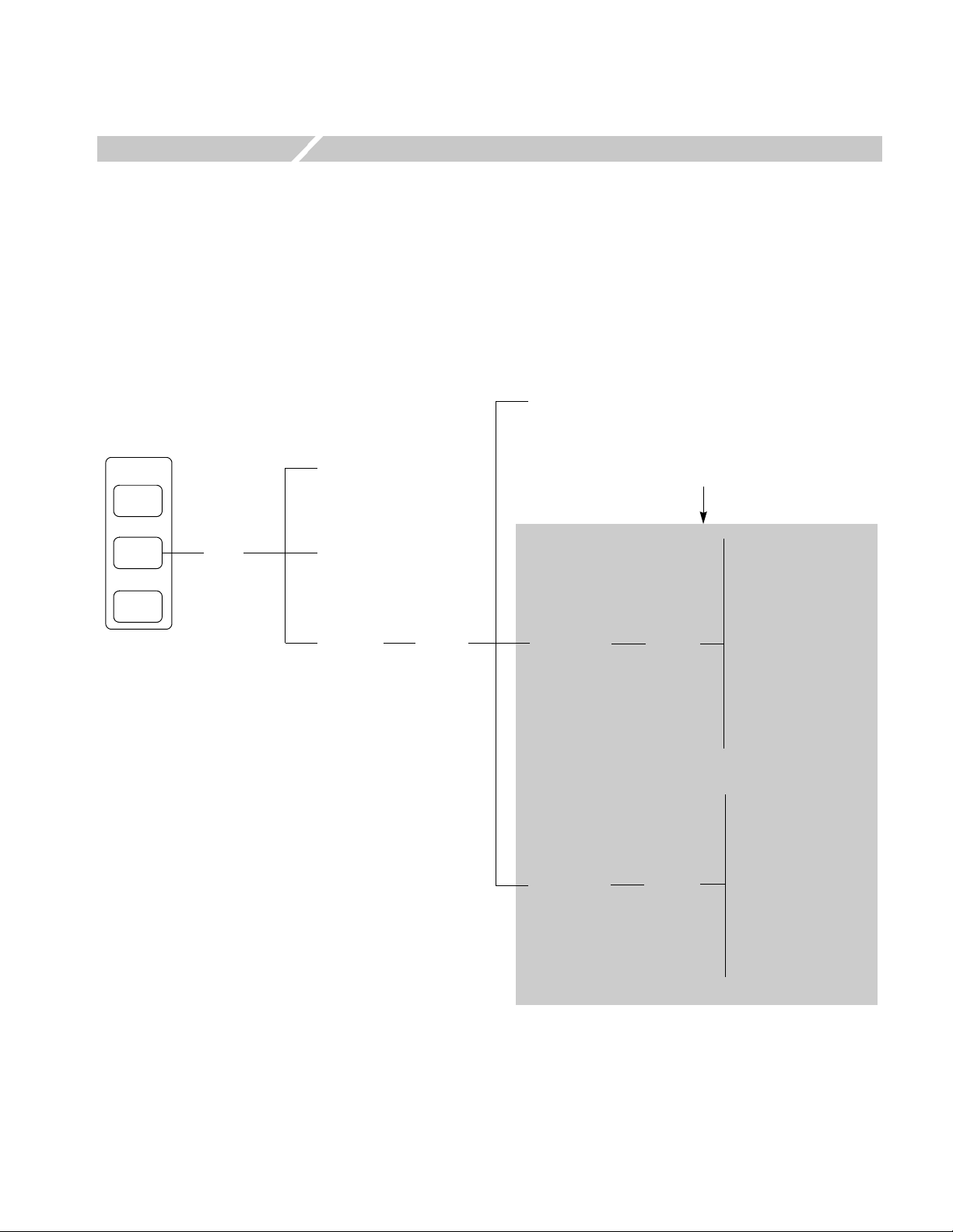
Figure 2-1 shows the measurement functions and how to access each measurement
function from the front-panel menu key.
Other option name
(if installed)
Mode
S/A
Demod
Time
Demod
menu
Analog Demod
Digital Demod
Standard...
Standard
menu
1xEV-DO-Fwd
1xEV-DO-Rev
Measurement functions
added by Option 26
Modulation Accuracy
Code Domain Power
Channel Power
OBW
Measure
menu
Measure
menu
ACPR
Spectrum Emission Mask
Gated Output Power
Intermodulation
CCDF
Pilot to Code Channel
Modulation Accuracy
Code Domain Power
Channel Power
OBW
ACPR
Spectrum Emission Mask
Intermodulation
CCDF
Pilot to Code Channel
Figure 2-1: Menu diagram showing measurement functions available in Option 26
RSA3303B, RSA3308B, & RSA3408B Option 26 User Manual 2-1

Functional Overview
Accessing a Measurement
Function
All of the measurement functions available in Option 26 can be selected from the
Demod (demodulation) mode.
Perform the following procedure to access any of the measurement functions:
1. Press the Demod key to open the Demod menu.
2. Press the Standard... side key to open the Standard menu.
3. Press the 1xEV-DO Fwd or 1xEV-DO Rev side key to open the Measure
menu for the standard.
4. Press one of the side keys to select the measurement that you want to perform.
If the desired measurement is not displayed on the current Measure menu,
press the Go to page 2 (of 2) side key to open the next page.
5. If needed, set frequency, span, and amplitude of the input signal.
Refer to your instrument user manual for information on how to set frequency,
span, and amplitude.
2-2 RSA3303B, RSA3308B, & RSA3408B Option 26 User Manual

1xEV-DO Forward Link Measurements
This section describes the functions and features of the 1xEV-DO forward link
measurements. Each measurement description contains general information about
the measurement, descriptions of the measurement displays and functions available
through menu selections.
The information is divided into the following subsections:
Modulation accuracy measurement
Code domain power measurement
Channel power measurement
OBW measurement
ACPR measurement
Spectrum emission mask measurement
Gated output power measurement
Intermodulation measurement
CCDF measurement
Pilot to code channel measurement
NOTE. If you are not familiar with the operation of the analyzer, refer to your
instrument user manual before reading this section.
RSA3303B, RSA3308B, & RSA3408B Option 26 User Manual 2-3
1xEV-DO Forward Link Measurements
Modulation Accuracy Measurement
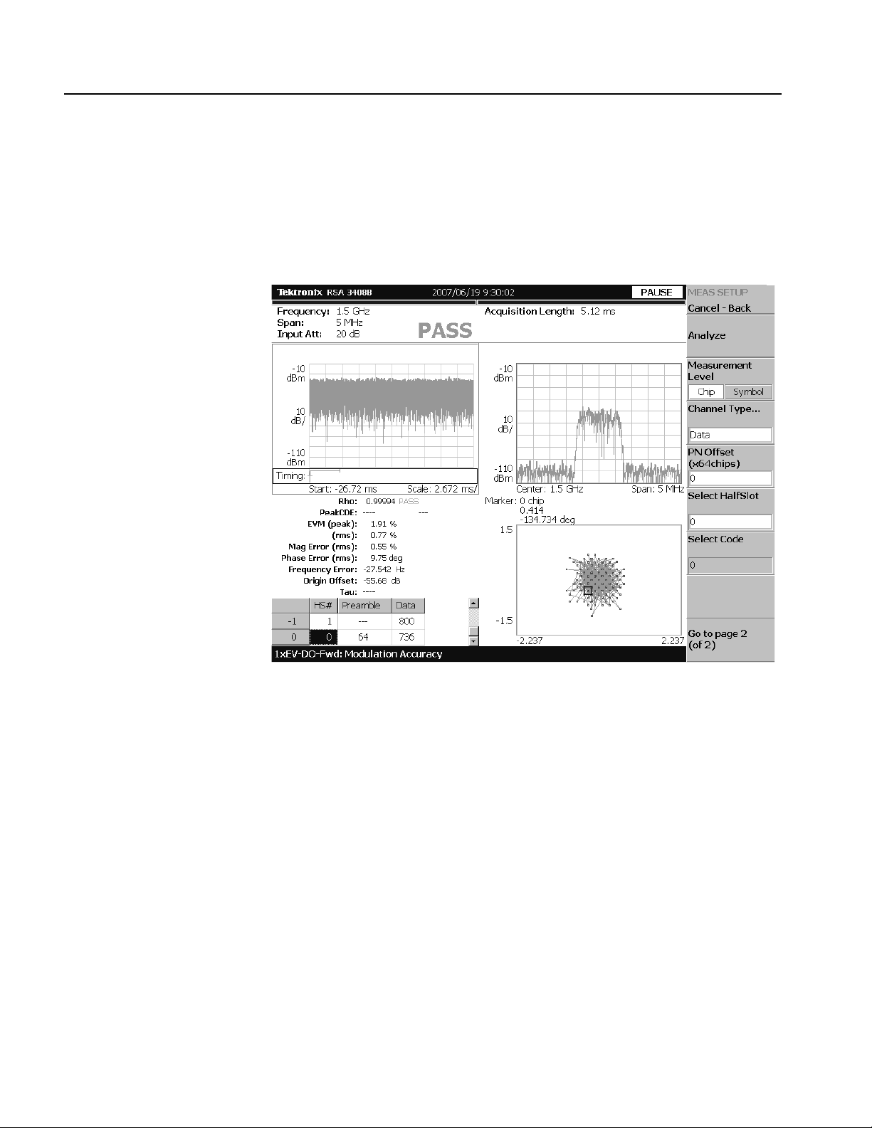
The modulation accuracy measurement measures Rho (ratio of the correlated
power to the total power), EVM (Error Vector Magnitude), magnitude error, phase
error, frequency error, and origin offset. Figure 2-2 shows an example of the
modulation accuracy measurement.
Figure 2-2: Modulation accuracy measurement
2-4 RSA3303B, RSA3308B, & RSA3408B Option 26 User Manual

1xEV-DO Forward Link Measurements
Display Elements
Setting the Acquisition and
Analysis Parameters
The following information is shown in the modulation accuracy measurement
display:
Overview: This view can contain power versus time or spectrogram.
Subview: This view can contain spectrum, EVM, magnitude error, phase
error, IQ power graph, and constellation.
Main view: This view can contain modulation accuracy, EVM, magnitude
error, phase error, and symbol table.
The display contents in each view can be changed using the View Define menu.
Refer to Changing the View Contents on page 2-7 for more information about the
View Define me n u.
You can set the following timing parameters using the Acquisition/Analysis menu.
Press the Acquisition/Analysis key to open the Acquisition/Analysis menu.
Acquisition (chips): Sets the acquisition length in chips. The range depends
on the acquisition memory size and the span setting.
Acquisition Length (s): Displays the acquisition length in seconds.
Acquisition History: Specifies the number of the block to display and
analyze. The latest block is number zero. Older blocks have larger negative
numbers.
Analysis Interval: Sets the analysis interval in half slots. The range depends
on the acquisition length setting.
Analysis Offset: Sets the start point of the analysis with respect to the left end
of the acquisition length in half slots.
Spectrum Length: Displays the time length for FFT processing of the
spectrum displayed in the subview. This value is equivalent to one frame
acquisition length.
Spectrum Offset: Sets the beginning of Spectrum Length with respect to the
left end of the acquisition length.
NOTE. Refer to your instrument user manual for detailed information about the
timing parameters.
RSA3303B, RSA3308B, & RSA3408B Option 26 User Manual 2-5

1xEV-DO Forward Link Measurements
Setting the Measurement
Parameters
You can set the following measurement parameters using the Meas Setup menu.
Press the Meas Setup key to open the Meas Setup menu.
Analyze: Performs analysis for the time slots in the analysis range.
Measurement Level: Selects the measurement level for the measurement.
You can select Chip (chip level) or Symbol (symbol level). When Overall is
selected in the Channel Type menu item, you cannot select Symbol.
Channel Type...: Select the channel type to be measured. When Symbol is
selected in the Measurement Level menu item, you can select MAC, Pilot,
Data, or Preamble. When Chip is selected in the Measurement Level menu
item, you can select Overall, MAC, Pilot, Data, or Preamble.
PN Offset: Sets the PN offset in units of 64 chips. You can set the value from
0 to 511.
Select HalfSlot: Sets the half slot for the measurement.
Select Code: Sets the code in the half slot for the measurement. This setting is
only available when Measurement Level is set to Symbol.
Active Channel Threshold: Sets the active channel threshold level (in dB
from the pilot) used for deciding whether a code channel is active or inactive.
You can set the value from −100 dB to 0 dB.
Measurement Filter...: Selects the measurement filter to apply when
calculating EVM and other modulation accuracy results. You can select None,
cdma2000, or cdma2000+EQ (equalizer).
IQ Swap: Sets whether to swap the I and Q data streams before demodulation.
Limits...: Sets the pass/fail limits for the modulation accuracy measurement.
When pressing this side key, the measurement limits editor appears. Refer to
Editing the Measurement Limits on page 2-61 for more information.
2-6 RSA3303B, RSA3308B, & RSA3408B Option 26 User Manual

1xEV-DO Forward Link Measurements
Changing the View
Contents
You can change the view contents in the overview, subview, and main view using
the View Define menu. Press the View: Define key to display the View Define
menu.
Show Views: Selects the view style on the screen. You can select Single or
Multi.
Overview Content...: Selects a view to display in the overview. You can
select Spectrogram or Waveform (power versus time).
Subview Content...: Selects a view to display in the subview:
Spectrum: Displays spectrum of the measured signal.
EVM: Displays changes of EVM (Error Vector Magnitude) over time.
MagErr: Displays changes of magnitude error over time.
PhaseErr: Displays changes of phase error over time.
IQ Power Graph: Displays changes of I and Q powers over time. Refer
to IQ Power Graph Display on page 2-21.
Constellation: Displays the signal as an I-Q constellation.
Mainview Content...: Selects a view to display in the main view. You can
select Modulation Accuracy, EVM, MagErr, PhaseErr, or Symbol Table. Refer
to Scale and Format in the Main View on page 2-8 for more information about
the views.
Menu Off: Hides the side menu. To display the menu again, press the MENU
side key or View: Define key.
RSA3303B, RSA3308B, & RSA3408B Option 26 User Manual 2-7

1xEV-DO Forward Link Measurements
Scale and Format in the
Main View
1: second half slot
This subsection describes the scale settings and display format in the main view.
Modulation Accuracy Display. When you select Mainview Content from the View
Define menu and then select Modulation Accuracy from the Mainview Content
submenu, an IQ rectangular graph and the measured value for Rho, peak code
domain error, rms and peak EVM, magnitude error, phase error, frequency error,
IQ origin offset, and Tau (timing error) are displayed (see Figure 2-3).The peak
code domain error is displayed only when the Measurement Level menu item is set
to Symbol, and Tau is displayed only when an external trigger signal is applied.
Half slot number
0: first half slot
Number of preamble chips
Number of data chips
IQ rectangular graph
(Vector display)
Figure 2-3: Modulation accuracy display
You can set the scale of the display using the Scale menu. Press the View:
Scale/Lines key, and then press the View Scale... side key to open the menu.
Measurement Content...: Selects vector or constellation display.
Ve ct or : Selects vector display. A signal represented with phase and amplitude
is displayed in rectangular (I and Q) coordinates. The red point indicates the
symbol position on the measured signal, and the yellow trace indicates the
locus of the signal between symbols.
Constellation: Selects constellation display. It is the same as the vector
display, except that only symbols of the measured signal are indicated in red,
and the locus between symbols is not shown. The cross marks indicate symbol
positions of an ideal signal.
NOTE. I and Q signals are normalized to prevent the scale from changing when
signal attenuation changes.
2-8 RSA3303B, RSA3308B, & RSA3408B Option 26 User Manual

1xEV-DO Forward Link Measurements
EVM Display. When you select Mainview Content from the View Define menu and
then select EVM from the Mainview Content submenu, changes of EVM (Error
Vector Magnitude) over time are displayed for each chip or symbol (see
Figure 2-4).
Symbol number
Horizontal Start
Code number and channel number
Vertical Scale
Vertical Start
Horizontal Scale
Figure 2-4: EVM display
You can set the scale of the display using the Scale menu. Press the View:
Scale/Lines key, and then press the View Scale... side key to open the menu.
Auto Scale: Sets the start value and the scale of the vertical axis to display the
entire waveform.
Horizontal Scale: Sets the scale of the horizontal axis (number of chips or
symbols).
Horizontal Start: Sets the chip number or symbol number of the first (left)
value of the horizontal axis.
Vertical Scale: Sets the scale of the vertical axis.
Vertical Start: Sets the minimum (bottom) value of the vertical axis.
Full Scale: Sets the scale of vertical axis to the default full-scale value.
Measurement Content...: Selects the display content in the main view. You
can select EVM, MagErr, or PhaseErr. This selection can also be made from
Mainview Content in the View Define menu.
RSA3303B, RSA3308B, & RSA3408B Option 26 User Manual 2-9
1xEV-DO Forward Link Measurements
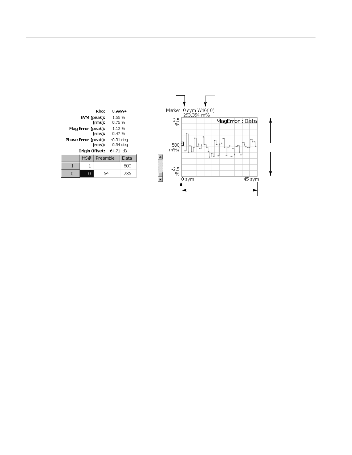
MagErr Display. When you select Mainview Content from the View Define menu
and then select MagErr from the Mainview Content submenu, changes of
magnitude error over time are displayed for each chip or symbol (see Figure 2-5).
Symbol number
Horizontal Start
Code length and channel number
Vertical Scale
Horizontal Scale
Figure 2-5: MagErr display
You can set the scale of the display using the Scale menu. Press the View:
Scale/Lines key, and then press the View Scale... side key to open the menu.
Auto Scale: Sets the start value and the scale of the vertical axis automatically
to display the entire waveform.
Horizontal Scale: Sets the scale of the horizontal axis (number of chips or
symbols).
Horizontal Start: Sets the chip number or symbol number of the first (left)
value of the horizontal axis.
Vertical Scale: Sets the scale of the vertical axis.
Vertical Offset: Sets the offset value of the vertical axis. You can set the value
from −200% to 200%.
Full Scale: Sets the scale of vertical axis to the default full-scale value.
Measurement Content...: Selects the display content in the main view. You
can select EVM, MagErr, or PhaseErr. This selection can also be made from
Mainview Content in the View Define menu.
2-10 RSA3303B, RSA3308B, & RSA3408B Option 26 User Manual

1xEV-DO Forward Link Measurements
PhaseErr Display. When you select Mainview Content from the View Define menu
and then select PhaseErr from the Mainview Content submenu, changes of phase
error over time are displayed for each chip or symbol (see Figure 2-6).
Symbol number
Horizontal Start
Code length and channel number
Vertical Scale
Horizontal Scale
Figure 2-6: PhaseErr display
You can set the scale of the display using the Scale menu. Press the View:
Scale/Lines key, and then press the View Scale... side key to open the menu.
Auto Scale: Sets the start value and the scale of the vertical axis automatically
to display the entire waveform.
Horizontal Scale: Sets the scale of the horizontal axis (number of chips or
symbols).
Horizontal Start: Sets the chip number or symbol number of the first (left)
value of the horizontal axis.
Vertical Scale: Sets the scale of the vertical axis.
Vertical Offset: Sets the offset value of the vertical axis. You can set the value
from −450 to 450 degrees.
Full Scale: Sets the scale of vertical axis to the default full-scale value.
Measurement Content...: Selects the display content in the main view. You
can select EVM, MagErr, or PhaseErr. This selection can also be made from
Mainview Content in the View Define menu.
RSA3303B, RSA3308B, & RSA3408B Option 26 User Manual 2-11
1xEV-DO Forward Link Measurements
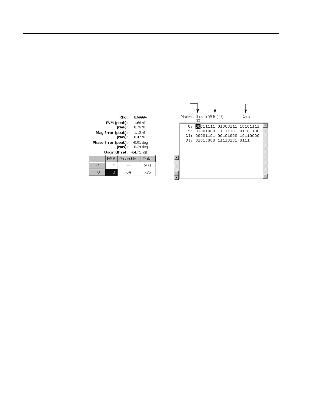
Symbol Table Display. When you select Mainview Content from the View Define
menu and then select Symbol Table from the Mainview Content submenu, the
symbol table is displayed (see Figure 2-7). This display is only available when the
Measurement Level menu item is set to Symbol.
Code length and channel number
Symbol number
Channel type
Figure 2-7: Symbol table display
You can set the radix for the display using the Scale menu. Press the View:
Scale/Lines key, and then press the View Scale... side key to open the menu.
Radix...: Sets the radix for displaying the table. You can select Hex
(hexadecimal), Oct (octal), or Bin (binary).
2-12 RSA3303B, RSA3308B, & RSA3408B Option 26 User Manual
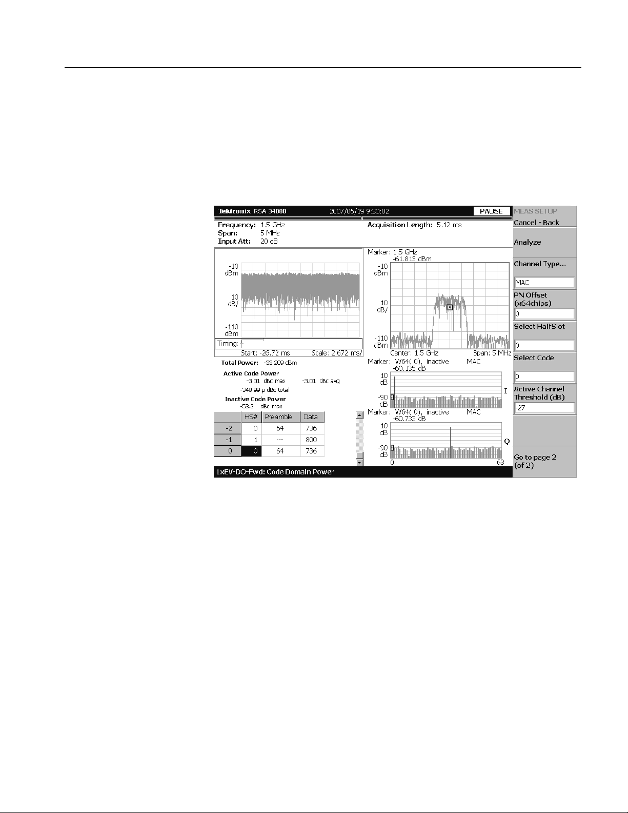
Code Domain Power Measurement
The code domain power measurement measures the distribution of signal power
across the set of code channels, normalized to the total signal power. This
measurement allows you to verify that each code channel is operating at its proper
level. Figure 2-8 shows an example of the code domain power measurement.
1xEV-DO Forward Link Measurements
Figure 2-8: Code domain power measurement
RSA3303B, RSA3308B, & RSA3408B Option 26 User Manual 2-13

1xEV-DO Forward Link Measurements
Display Elements
Setting the Acquisition and
Analysis Parameters
The following information is shown in the code domain power measurement
display:
Overview: This view can contain power versus time or spectrogram.
Subview: This view can contain spectrum, EVM, magnitude error, phase
error, IQ power graph, and constellation.
Main view: This view can contain code domain power, power codogram, and
IQ power graph.
The display contents in each view can be changed using the View Define menu.
Refer to Changing the View Contents on page 2-16 for more information about the
View De fi n e m e n u .
You can set the following timing parameters using the Acquisition/Analysis menu.
Press the Acquisition/Analysis key to open the Acquisition/Analysis menu.
Acquisition Length (chips): Sets the acquisition length in chips. The range
depends on the acquisition memory size and the span setting.
Acquisition Length (s): Displays the acquisition length in seconds.
Acquisition History: Specifies the number of the block to display and
analyze. The latest block is number zero. Older blocks have larger negative
numbers.
Analysis Interval: Sets the analysis interval in half slots. The range depends
on the acquisition length setting.
Analysis Offset: Sets the start point of the analysis with respect to the left end
of the acquisition length in half slots.
Spectrum Length: Display the time length for FFT processing of the spectrum
displayed in the subview. This value is equivalent to one frame acquisition
length.
Spectrum Offset: Sets the beginning of Spectrum Length with respect to the
left end of the acquisition length.
NOTE. Refer to your instrument user manual for detailed information about the
timing parameters.
2-14 RSA3303B, RSA3308B, & RSA3408B Option 26 User Manual
 Loading...