

Page 1

x
RSA306, RSA306B, and
RSA500A/600A Series
Spectrum Analyzers
Application Programming Interface (API)
ZZZ
Programming Reference
$
077-1031-05
Page 2

Page 3

xx
RSA306, RSA306B, and
RSA500A/600A Series
Spectrum Analyzers
Application Programming Interface (API)
ZZZ
Programming Reference
www.tek.com
077-1031-05
Page 4

Copyright © Tektronix. All rights reserved. Licensed software products are owned by Tektronix or its subsidiaries or suppliers, and are
protected by na
tional copyright laws and international treaty provisions.
Tektronix pro
previously published material. Specifications and price change privileges reserved.
TEKTRONIX and TEK are registered trademarks of Tektronix, Inc.
ducts are covered by U.S. and foreign patents, issued and pending. Information in this publication supersedes that in all
Contacting Tektronix
Tektronix, Inc.
14150 SW Karl Braun Drive
P.O. Box 500
Beaverton, OR 97077
USA
For product information, sales, service, and technical support:
In North America, call 1-800-833-9200.
Worldwide, visit www.tek.com to find contacts in your area.
Page 5

Table of Contents
Preface ................................................................................................................................. ii
API function
Alignment functions.................................................................................................................... 2
Audio functions ........................................................................................................................ 3
Configure fu
Device functions...................................................................................................................... 21
DPX functions......................................................................................................................... 28
GNSS funct
IF streaming functions................................................................................................................ 45
IQ block functions..................................................................................................................... 55
IQ streami
Playback functions (R3F file format)................................................................................................. 84
Power functions....................................................................................................................... 86
Spectrum
Time functions ........................................................................................................................ 94
Tracking generator functions . . . .. . . .. . . .. . . .. . . .. . . .. . . ... . ... . .. . . ... . ... . ... . ... . ... . ... . ... . ... . . .. . . .. . . .. . . .. . . .. . . .. . . ... . ..... 98
Trigger
Example Python program .......................................................................................................... 104
Stream
RSA API version compatibility ......................................................................................................111
Index
groups. ... ... .... . . ... . ... . . .. . . ... . ... . . .. . . ... . ... . . .. . . ... . ... . . ... . ... . . .. . . ... . ... . . .. . . ... . ... . . .. . . ... . ... . . ... . ... 1
nctions.................................................................................................................... 7
ions....................................................................................................................... 40
ng functions ............................................................................................................... 63
functions ................................................................................................................... 87
functions .................................................................................................................... 100
Programming file attachment ................................................................................................. 105
ing IF Sample Data File Format............................................................................................ 106
Table of Content
s
API Reference i
Page 6

Preface
Preface
This document describes the RSA API function calls to interface with the RSA306, RSA306B, RSA500A Series, and
RSA600A Series Spectrum Analyzers through Microsoft Windows and Linux based OS (Centos 7, Debian 10 and Ubuntu).
The RSA API driver software allows user-developed programs to directly control Tektronix RSA USB devices. The API
software i s designed to be used with PCs running the Microsoft Windows. To use the API software, it must be installed on the
PC to which the RSA device is connected. The API software installer can be accessed as follows:
To access driver from the USB memory device that shipped with your instrument: Open the USB drive, navigate to the
API installer, and install the driver.
To access driver from www.Tek.com: Search for “RSA API” and filter the results on “Software”. Download and install the
latest driver.
Programing languages supported by this driver include: C, C++, and Python. An example program written in Python is
provided. (See page 105, Programming file attachment.)
For Microsoft Windows
The main API interface DLL file is RSA_API.dll. It is a C-language Win32 DLL file created in Microsoft Visual Studio. The API
uses standard Windows C-runtime libraries which must also be installed on the PC. A linker library file (RSA_API.lib) is
provided
to support static linking of the API to user C/C++ programs.
For Linux
For Linux based OS, two shared objects are needed to access the USB RF Instruments through API. The shared objects
(.so) files are 64-bit files created for Linux based OS. Before using the shared objects, you need to follow the installation
instructions shipped as part of the API Package. Example C/Python programs are also shipped as part of that package.
This document supports API version 2. A compatibility chart from API version 1 to version 2 is provided. (See page 111, RSA
API version compatibility.)
ii API Reference
Page 7

API function gro
ups
API function g
This section contains the available function calls. The functions are grouped into the following categories:
Alignment (See page 2.)
Audio (See page 3.)
Configure (See page 7.)
Device (See page 21.)
DPX (See page 28.)
GNSS (See page 40.)
IF streaming (See page 45.)
IQ block (See page 55.)
IQ streaming (See page 63.)
Playback (See page 84.)
Power (See page 86.)
Spectrum (See page 87.)
Time (See page 94.)
roups
Tracking generator (See page 98.)
Trigger (See page 100.)
API Reference 1
Page 8

Alignment funct
ions
Alignment fun
ALIGN_GetAli
Declaration:
Parameters:
Return Values:
Addition
ALIGN_Ge
Declaration:
Parameters:
Return Values:
Additional Detail:
gnmentNeeded
needed: Pointer to a bool. True indicates an alignment is needed. False indicates an
noError:
errorNotConnected:
al Detail:
tWarmupStatus
warmedUp: Pointer to a bool.
noError:
ctions
Determines if
ReturnStatu
alignment is not needed.
The function has completed successfully.
The device
It is based on the difference between the current temperature and the
temperature from the last alignment.
Reports device warm-up status.
ReturnS
True indicates the device's warm-up interval has been reached. False indicates
the war
The function has completed successfully.
Devices start in the "warm-up" state after initial power up until the internal
erature stabilizes. The warm-up interval is different for different devices.
temp
an alignment is needed or not.
s ALIGN_GetAlignmentNeeded(bool* needed);
is not connected.
tatus ALIGN_GetWarmupStatus(bool* warmedUp);
m-up interval has not been reached.
ALIGN_RunAlignment
aration:
Decl
urn Values:
Ret
noError: The alignment has succeeded.
errorDataNotReady:
the device alignment process.
Runs
ReturnStatus ALIGN_RunAlignment();
The alignment operation failed.
2 API Reference
Page 9

Audio functions
Audio functio
AUDIO_SetFre
Declaration:
Parameters:
Return Values:
Additional Detail:
AUDIO_GetFrequencyOffset Queries the audio carrier frequency offset from the Center Frequency.
Declar
Parame
Retur
quencyOffset
freqOffsetHz: Amount of frequency offset from the Center Frequency.
noError:
errorParameter:
ation:
ters:
ffsetHz:
freqO
n Values:
noError:
ns
Sets the audio
ReturnStatu
Range: –20e
The function completed successfully.
Input parameter out of range.
This function allows the audio demodulation carrier frequency to be offset from
the devic
without changing the Center Frequency. The audio demodulation is performed
at a carrier frequency of (Center Frequency + freqOffsetHz). The freqOffsetHz
is set to
ReturnStatus AUDIO_GetFrequencyOffset(double* freqOffsetHz);
er to a double variable. Returns the current audio frequency offset from
Point
the Center Frequency in Hz.
unction completed successfully.
The f
demodulation carrier frequency offset from the Center Frequency.
s AUDIO_SetFrequencyOffset(double freqOffsetHz);
6 ≤ freqOffsetHz ≤ 20e6
e’s Center Frequency. This allows tuning different carrier frequencies
an initial value of 0 Hz at the time the device is connected.
AUDIO_GetEnable Queries the audio demodulation run state.
aration:
Decl
ameters:
Par
qOffsetHz:
fre
Return Values:
noError:
ReturnStatus AUDIO_GetEnable(bool *enable);
Pointer to bool variable. True indicates the audio demodulation is running.
se indicates it is stopped.
Fal
The query was successful.
API Reference 3
Page 10

Audio functions
AUDIO_GetData Returns audio s
Declaration:
Parameters:
data:
inSize: The maximum
outSize: The amount of audio data samples stored in the data array.
Return Val
Additional Detail
AUDIO_GetMode Queries the audio demodulation mode.
Declaration:
Parameters:
Return Values:
Add
ues:
noError:
_mode:
rror:
noE
itional Detail:
ReturnStatus
Pointer to a 16 bit integer array. Contains an array of audio data when the
function com
will not exceed this value.
The data pa
The outSi
The inSize value specifies the maximum amount of audio samples allowed.
ReturnStatus AUDIO_GetMode(AudioDemodMode* _mode);
Pointer to AudioDemodMode mode. Contains the audio demodulation mode
when the function completes.
AudioDemodMode Value
ADM_F
ADM_FM_13KHZ
ADM_FM_75KHZ
ADM_
ADM_AM_8KHZ
ADM_MODE_NONE
The audio demodulation mode has been successfully queried.
mode type is stored in the _mode parameter.
The
ample data in a user buffer.
AUDIO_GetData(int16_t* data, uint16_t inSize, uint16_t* outSize);
pletes.
amount of audio data samples allowed. The outSize parameter
rameter is filled with audio data.
ze variable specifies the amount of audio samples stored in the array.
M_8KHZ
FM_200KHZ
0
1
2
3
4
5
AUDIO_GetMute Queries the status of the mute operation.
claration:
De
rameters:
Pa
mute:
_
Return Values:
noError:
Additional Detail:
4 API Reference
ReturnStatus AUDIO_GetMute(bool* _mute);
ointer to a bool. Contains the mute status of the output speakers when the
P
function completes.
True indicates the speaker output is muted. False indicates the speaker output
s not muted.
i
The mute status has been successfully queried.
The status of the mute operation does not stop the audio processing or data
callbacks.
Page 11

Audio functions
AUDIO_GetVolu
Declaration:
Parameters:
Return Values:
Additional
AUDIO_SetMode Sets the audio demodulation mode.
Declaration:
Parameters:
Return
me
_volume:
noError:
Detail:
mode: AudioDem
Values:
noError:
Queries the vol
ReturnStatus
Pointer to a float. Contains a real number ranging from 0 to 1.
The volume has been successfully queried.
If the value is outside of the specified range, clipping occurs.
ReturnStatus AUDIO_SetMode(AudioDemodMode mode);
ADM_FM_8KHZ
ADM_FM_
ADM_FM_75KHZ
ADM_FM_200KHZ
ADM_AM_
ADM_MODE_NONE
The aud
ume and must be a real value ranging from 0 to 1.
AUDIO_GetVolume(float* _volume);
odMode
13KHZ
8KHZ
io demodulation mode has been successfully set.
Value
0
1
2
3
4
5
AUDIO_SetMute Sets the mute status.
ration:
Decla
Param
mute
Return Values:
noError:
Additional Detail:
IO_SetVolume
AUD
Declaration:
Parameters:
volume: Volume value.
Return Values:
oError:
n
Additional Detail:
eters:
:
ReturnStatus AUDIO_SetMute(bool mute);
Mute status. True mutes the output speakers. False restores the output speaker
d.
soun
The mute status has been successfully set.
It does not affect the data processing or callbacks.
s the volume value and must be a real number ranging from 0 to 1.
Set
turnStatus AUDIO_SetVolume(float volume);
Re
Range: 0.0 to 1.0.
The volume has successfully been set.
If the value is outside of the specified range, clipping occurs.
API Reference 5
Page 12

Audio functions
AUDIO_Start Starts the audi
Declaration:
ReturnStatus
o demodulation output generation.
AUDIO_Start();
Return Values:
noError: The audio demodulation output generation has started.
AUDIO_Stop Stops the audio demodulation output generation.
Declaration:
ReturnStatus AUDIO_Stop()
Return Values:
noError: The audio de
modulation output generation has stopped.
6 API Reference
Page 13

Configure functi
ons
Configure func
CONFIG_GetCe
Declaration:
Parameters:
Return Values:
Addition
CONFIG_GetExternalRefEnable Queries the state of the external reference.
Declaration:
Parameters:
Retur
nterFreq
cf: Pointer to a double. Contains the center frequency when the function completes.
noError:
errorNotConnected:
al Detail:
exRefEn: Pointer to a bool. Contains the status of the external reference when the
n Values:
noError:
tions
Queries the ce
ReturnStatu
The center frequency has been queried.
The device
The center frequency determines the center location for the spectrum view.
ReturnStatus CONFIG_GetExternalRefEnable(bool* exRefEn);
function completes.
True in
reference is disabled.
nction has completed successfully.
The fu
nter frequency.
s CONFIG_GetCenterFreq(double* cf);
is not connected.
dicates the external reference is enabled. False indicates the external
CONFIG_GetExternalRefFrequency Queries the frequency of the external reference.
aration:
Decl
meters:
Para
extFreq:
urn Values:
Ret
noError:
rrorExternalReferen-
e
ceNotEnabled:
dditional Detail:
A
ONFIG_GetFrequencyReference-
C
Source
Declaration:
ReturnStatus CONFIG_GetExternalRefFrequency(double* extFreq);
nter to a double. On return, contains the frequency in Hz of the attached
Poi
external reference input.
e function has completed successfully.
Th
he external reference input is not in use.
T
The external reference input must be enabled for this function to return useful
results.
ueries the Frequency Reference source.
Q
ReturnStatus CONFIG_GetFrequencyReferenceSource(FREQREF_SOURCE*
src);
API Reference 7
Page 14

Configure functi
ons
Parameters:
src:
Return Values:
noError:
errorNotConnected:
Additional Detail:
Pointer to variable to return current Frequency Reference source selection. See
CONFIG_SetFr
The function has completed successfully.
The device is not connected.
This function can (and should) be used in place of
CONFIG_Ge
CONFIG_GetExternalRefEnable() only indicates if the EXTREF is chosen or
not while this function indicates a ll available sources.
equencyReferenceSource for the list of result values.
tExternalRefEnable() to query the Frequency Reference source.
CONFIG_Ge
CONFI
tMaxCenterFreq
Declaration:
Parameters:
maxCF: Pointer to a double. Contains the maximum center frequency when the function
Return Values:
noError:
errorNotConnected:
Additional Detail:
G_GetMinCenterFreq
Declaration:
Parameters:
minCF: Pointer to a double. Contains the m in imum center frequency when the function
Return Values:
noError:
errorNotConnected:
Additional Detail:
Queries th
ReturnSt
complet
The maximum center frequency value has been queried.
The device is not connected.
The value is stored in the maxCF parameter.
Queri
Retu
com
The minimum center frequency value has been queried.
The device is not connected.
The value is stored in the minCF parameter.
e maximum center frequency.
atus CONFIG_GetMaxCenterFreq(double* maxCF);
es.
es the minimum center frequency.
rnStatus CONFIG_GetMinCenterFreq(double* minCF);
pletes.
8 API Reference
Page 15

Configure functi
ons
CONFIG_GetMod
rection
Declaration:
Parameters:
mode:
Return V
noError:
errorN
Additional Detail:
CONFIG_GetReferenceLevel Queries the reference level.
Decla
meters:
Para
refL
urn Values:
Ret
noError:
er
Additional Detail:
eGnssFreqRefCor-
alues:
otConnected:
ration:
evel:
rorNotConnected:
This command is
Queries the operating mode of the GNSS Frequency Reference correction.
ReturnStatus CONFIG_GetModeGnssFreqRefCorrection(GFR_MODE* mode);
Pointer to va
Valid results are:
GFR_MODE
GFRM_OFF
GFRM_FREQTRACK
GFRM_PHASETRACK
GFRM_HOLD
The func
The device is not connected.
GFRM_
ReturnStatus CONFIG_GetReferenceLevel(double* refLevel);
Poin
Range: –130 dBm to 30 dBm.
The
The device is not connected.
Th
tion completed suc cess fully.
OFF (0) is returned when GNSS source is not selected.
ter to a double. Contains the reference level when the function completes.
function has completed successfully.
e value is stored in the refLevel parameter.
for RSA500A Series and RSA600A Series instruments only.
riable to return GNSS Frequency Reference operating mode.
Value
0
2
3
4
CONFIG_Preset This function sets the trigger mode to Free Run, the center frequency to 1.5
GHz, the span to 40 MHz, the IQ record length to 1024 samples and the
eference level to 0 dBm.
r
Declaration:
Return Values:
noError: The preset values have been set.
errorNotConnected:
eturnStatus CONFIG_Preset();
R
The device is not connected.
API Reference 9
Page 16

Configure functi
ons
CONFIG_SetCen
Declaration:
Parameters:
Return Values:
Additional Detail: When using the tracking generator, the tracking generator output
CONFIG_De
tingString
Declarat
Parameters:
turn Values:
Re
Additional Detail:
terFreq
cf: Value to set Center Frequency, in Hz. The value must be within the range
noError:
errorNotConnected:
codeFreqRefUserSet-
ion:
:
i_usstr
o_fui: Pointer to a FREQREF_USER_INFO structure to return the User setting values
noError:
rrorNotConnected:
e
Sets the center
ReturnStatus
MinCF to M axC
The center frequency has been queried.
The device is not connected.
(TRKGEN_SetOutputLevel) should be set prior to setting the center frequency.
This comma
Decodes a formatted User setting string into component elements.
CONFIG_DecodeFreqRefUserSettingString (const char* i_usstr,
FREQREF_USER_INFO* o_fui);
Pointer to a char array containing a formatted User setting string.
decoded from the input string. The structure definition is as follows:
Structure element
bool isvalid
unsigned int dacValue
char datetime[DEV-
INFO_MAX_STRLEN]
uble temperature
do
he function completed successfully.
T
The device is not connected.
This function can be used to decode a user setting string into the component
items in the string.
frequency value.
CONFIG_SetCenterFreq(double cf);
F.
nd is for RSA500A Series and RSA600A Series instruments only.
Description
True if the User setting string has
d data in it, false if not. If false,
vali
the remaining elements below are
invalid.
Control DAC value.
Char string of date+time the User
ting value was created. Format
set
“YYYY-MM-DDThh:mm:ss”.
vice temperature when the User
De
setting data was created.
10 API Reference
Page 17

Configure functi
ons
CONFIG_GetEna
fAlign
Declaration:
Parameters:
Return Values:
Additiona
CONFIG_SetEnableGnssTimeRefAlign
Declaration:
Parameters:
Return Values:
Additional Detail:
bleGnssTimeRe-
enable:
noError:
errorNotConnected:
l Detail:
enable:
noError:
errorNotConnected:
This command is
Queries the control setting of API Time Reference alignment from the internal
GNSS receiver.
ReturnStatus CONFIG_GetEnableGnssTimeRefAlign (bool* enable);
True means the time reference setting is enabled. False means the time
reference setting is disabled.
The function completed successfully.
The device
The GNSS receiver must be enabled to use this function.
This command is for RSA500A Series and RSA600A Se ries instruments only.
Controls the API Time Reference alignment from the internal GNSS receiver.
ReturnStatus CONFIG_SetEnableGnssTimeRefAlign (bool enable);
True enables setting time reference. False disables setting time reference.
The setting time reference has been enabled or disabled.
The device is not connected.
The GNSS receiver must be enabled to use this function.
The default control setting of “true” enables the API time reference system to be
aligned precisely to UTC time from the GNSS navigation message and 1PPS
signal. The GNSS receiver must achieve navigation lock for the time reference
alignment to occur. While GNSS is locked, the time reference is updated every
10 seconds to keep close synchronization with GNSS time. Setting the control to
“false” disables the time reference updating from GNSS, but retains the current
time reference setting. This control allows the user application to independently
set the time reference, or simply prevent time updates from the GNSS.
for RSA500A Series and RSA600A Series instruments only.
is not connected.
CONFIG_SetExternalRefEnable Enables or disables the external reference.
Declaration:
Parameters:
exRefEn: Enables or disables the external reference.
Return Values:
noError:
errorNotConnected:
errorTimeout:
Additional Detail:
API Reference 11
ReturnStatus CONFIG_SetExternalRefEnable(bool exRefEn);
True enables the external reference. False disables the external reference.
The external reference has been enabled or disabled.
The device is not connected.
The operation has not finished after 2 seconds.
When the external reference is enabled, an external reference signal must be
connected to the “Ref In” port. The signal must have a frequency of 10 MHz
with a +10 dBm maximum amplitude. This signal is used by the local oscillators
to mix with the input signal.
When the external reference is disabled, an internal reference source is used.
Page 18

Configure functi
ons
CONFIG_SetFre
Source
Declaration:
Parameters:
src:
Return V
Additional Detail:
alues:
noError:
NotConnected:
error
LOLockFailure:
error
errorParameter: Invalid input parameter.
quencyReference-
Selects the dev
ReturnStatus CONFIG_SetFrequencyReferenceSource(FREQREF_SOURCE
src);
Frequency Reference source selection. Valid settings are:
FREQREF_SOURCE
FRS_INTERNAL
FRS_EXTREF
FRS_GNSS
FRS_USER
NOTE. RSA306B and RSA306 support only INTERNAL and EXTREF sources.
The fun
The device is not connected.
d to lock to External Reference input.
Faile
This function can (and should) be used in place of CONFIG_Se-
ernalRefEnable() to control the Frequency Reference source.
tExt
CONFIG_SetExternalRefEnable() only allows selecting the INTERNAL or
EXTREF sources, while this function allows choice of all available sources.
INTERNAL source is always a valid selection, and is never switched out
The
of automatically.
The EXTREF source uses the signal input to the Ref In connector as frequency
erence for the internal oscillators. If EXTREF is selected without a valid
ref
signal connected to Ref In, the source automatically switches to USER if
available, or to INTERNAL otherwise. If lock fails, an error status indicating
e failure is returned.
th
The GNSS source uses the internal GNSS receiver to discipline (adjust) the
internal reference oscillator. If GNSS source is selected, the GNSS receiver
ust be enabled. If the GNSS receiver is not enabled, the source selection
m
remains GNSS, but no frequency correction is done. G NS S disciplining only
occurs when the GNSS receiver has navigation lock. When the receiver is
nlocked, the adjustment setting is retained unchanged until receiver lock is
u
achieved or the source is switched to another selection.
If USER source is selected, the previously set USER setting is used. If the
USER setting has not been set, the source switches automatically to INTERNAL.
ice Frequency Reference source.
Value
0
1
2
3
ction completed successfully.
12 API Reference
Page 19

Configure functi
ons
CONFIG_GetSta
rection
Declaration:
Parameters:
state:
quality:
turn Values:
Re
noError:
rrorNotConnected:
e
Additional Detail:
tusGnssFreqRefCor-
This command is
for RSA500A Series and RSA600A Series instruments only.
Queries the status of the GNSS Frequency Reference correction.
ReturnStatus CONFIG_GetStatusGnssFreqRefCorrection(GFR_STATE* state,
GFR_QUALITY* quality);
Pointer to variable to return the GNSS Frequency Reference correction state.
Valid settings are:
GFR_STATE
GFRS_OFF
GFRS_ACQUIRING
GFRS_FREQTRACKING
GFRS_PHASETRACKING
GFRS_HOLDING
Value
0
1
2
3
4
Pointer to variable to return the GNSS Frequency Reference correction tracking
y.
qualit
UALITY
GFR_Q
INVALID
GFRS_
_LOW
GFRS
_MEDIUM
GFRS
S_HIGH
GFR
TE. INVALID quality is returned if state is not FREQTRACKING or
NO
Value
0
1
2
3
PHASETRACKING.
he function completed successfully.
T
The device is not connected.
The GNSS receiver must be enabled and selected as the Frequency Reference
source (FRS_GNSS) to use this function.
The “state” value indicates the current internal state of the GNSS Frequency
Reference adjustment system. The states mostly correspond to the possible
control modes, but also indicate how initialization and/or tracking is going.
GRFS_OFF: GNSS not selected as Frequency Reference source.
GFRS_ACQUIRING: Initial synchronization and alignment of the oscillator
is occurring. This is the first state entered when GNSS source is selected. It
remains in this state until the GNSS receiver achieves navigation lock. Until
the receiver locks, no frequency adjustments are done. It continues in this
state until oscillator adjustments bring the internal oscillator frequency within
-6
±1x10
(1 ppm) of the ideal GNSS 1PPS frequency.
GRFS_FREQTRACKING: Fine adjustment of the reference oscillator
is occurring. Only small adjustments are allowed in this state. The
adjustments attempt to minimize the difference between the 1PPS pulse
frequency and the internal oscillator frequency.
GRFS_PHASETRACKING: Fine adjustment of the reference oscillator is
occurring. Only small adjustments are allowed in this state. The adjustments
attempt to maintain the sample timing at a consistent relationship to the
1PPS signal interval. If the timing c annot be maintained within ±100 μsec
range, the state will transition to GRFS_FREQTRACKING.
API Reference 13
Page 20

Configure functi
ons
GFRS_HOLDING
: Frequency adjustments are disabled. This may be
caused by intentionally setting the mode to GFRM_HOLD. It may also occur
if GNSS navigation lock is lost. During the unlock interval, the HOLDING
stateisineff
ect and the most recent adjustment setting is maintained.
The “quality” indicates how well the frequency adjustment is performing. It is valid
only when “state” is GRFS_FREQTRACKING or GRFS_PHASETRACKING;
otherwise, i
t returns INVALID. The quality state values are:
GFRQ_LOW: Frequency error is > ±0.2 x 10
6
GFRQ_MEDIUM:±0.2 x 10
(0.2 ppm) > Frequency error > ±0.025 x 10
6
(0.2 ppm)
6
(0.025 ppm)
GFRQ_HIGH: Frequency error < ±0.025 x 10
6
(0.025 ppm)
14 API Reference
Page 21

Configure functi
ons
CONFIG_SetMod
rection
Declaration:
Parameters:
mode:
Return Values:
noError:
errorNotConnected:
errorParameter:
Additional Detail:
eGnssFreqRefCor-
This command is
Controls the operating mode of the GNSS Frequency Reference correction.
ReturnStatus CONFIG_SetModeGnssFreqRefCorrection(GFR_MODE mode);
GNSS Frequen
GFR_MODE
GFRM_FREQT
GFRM_PHAS
GFRM_HOL
NOTE. GFR
The function completed successfully.
The device is not connected.
Invalid input parameter or GNSS not selected as Frequency Reference source.
The GNSS receiver must be enabled and selected as the Frequency Reference
e (FRS_GNSS) to use this function. An error status is returned if it is
sourc
not selected.
The default mode is FREQTRACK. When the GNSS source is selected, this
is always set initially. O ther modes must be set explicitly after selecting
mode
GNSS source. If the GNSS source is deselected and later reselected, the mode
is set to FREQTRACK. There is no memory of previous mode settings. The
setting may be changed at any time while GNSS is selected. However,
mode
control changes may take up to 50 msec to be processed, so should not be
posted at a high rate. If multiple control changes are posted quickly, the function
l “stall” after the first one until each change is accepted and processed, taking
wil
50 msec per change.
FREQTRACK mode uses the GNS S internal 1PPS pulse as a high-accuracy
equency source to correct the internal reference oscillator frequency. It adjusts
fr
the oscillator to minimize the frequency difference between it and the 1PPS
signal. This is the normal operating mode, and can usually be left in this mode
less special conditions call for switching to the other modes. When need for
un
the other modes is over, FREQT RA CK mode should be restored.
PHASETRACK mode is similar to FREQTRACK mode, as it adjusts the
eference oscillator based on the 1PPS signal. However, it attempts to maintain,
r
on average, a consistent number of oscillator cycles within a 1PPS interval.
This is useful when recording long IF or IQ data records, as it keeps the data
ample timing aligned over the record, to within +/-100 nsec of the 1PPS
s
time location when the mode is initiated. PHASETRACK mode does more
oscillator adjustments than FREQTRACK mode, so it should only be used
when specifically needed for long-term recording. When GNSS source is first
selected, FREQTRACK mode should be selected until the tracking quality has
reached MEDIUM, before using PHASETRACK mode.
HOLD mode pauses the oscillator adjustments w ithout stopping the GNSS
monitoring. This can be used to prevent oscillator adjustments during
acquisitions. Remember that the mode change can take up to 50 msec to be
accepted.
for RSA500A Series and RSA600A Series instruments only.
cy Reference operating mode. Valid settings are:
Value
RACK
ETRACK
D
M_OFF (0) is not a valid mode setting.
2
3
4
API Reference 15
Page 22

Configure functi
ons
CONFIG_GetSta
fAlign
Declaration:
Parameters:
enable:
Return Values:
noError:
errorNotConnected:
Additional Detail:
CONFIG_
GetFreqRefUserSetting
Declaration:
Parameters:
o_usstr:
tusGnssTimeRe-
This command is
Queries the status of API Time Reference alignment from the internal GNSS
receiver.
ReturnStatus CONFIG_GetStatusGnssTimeRefAlign (bool* aligned);
Pointer to variable to return time reference s etting status.
true: time reference has been set from GNSS receiver.
false: time
The function completed successfully.
The device is not connected.
The GNSS receiver must be enabled to use this function.
If GNSS ti
nssTimeRefAlign()), this function returns “false” status even if the time reference
was previously set from the GNSS receiver.
This com
Gets the Frequency Reference User-source setting value in formatted s tring
form.
CONFIG_GetFreqRefUserSetting (char* o_usstr);
Pointer to a char array to return the formatted user setting string:
$FRU,<devType>,<devSN>,<dacVal>,<dateTime>,<devTemp>*<CS>
Where
<devType> : device type
<devSN> : device serial number
<dac
<dateTime> : date and time of creation, fmt: YYYY-MM-DDThh:mm:ss
<devTemp> : device temperature (degC) at creation
<CS
mand is for RSA500A Series and RSA600A Series instruments only.
:
Val> : integer DAC value
> : integer checksum of chars before ‘*’ char
for RSA500A Series and RSA600A Series instruments only.
reference has not been set from GNSS receiver.
me reference setting is disabled (see CONFIG_GetEnableG-
Ex: “$FRU,RSA503A,Q000098,2062,2016-06-06T18:11:08,51.41*87”
he User setting is not valid,then the user string result returns the string
If t
“Invalid User Setting”.
turn Values:
Re
noError:
rrorNotConnected:
e
Additional Detail:
16 API Reference
e function completed successfully.
Th
The device is not connected.
This function is normally only used when creating a User setting string
for external non-volatile storage. It can a lso be used to query the current
User setting data in case the ancillary information is desired. The
CONFIG_DecodeFreqRefUserSettingString() function can then be used to
extract the individual items.
Page 23

Configure functi
ons
CONFIG_SetFre
Declaration:
Parameters:
i_usstr:
Return Values:
noError:
errorNotConnected:
errorPar
nal Detail:
Additio
qRefUserSetting
ameter:
This command is
Sets the Frequency Reference User-source setting value.
CONFIG_SetFreqRefUserSetting(const char* i_usstr);
If i_usstr is
User setting memory.
Otherwise, the input pointer must point to a char string as formatted by the
CONFIG_Get
decodes correctly and matches device), it is used to set the User setting
memory. If the string is invalid, the User setting is not changed.
The function completed successfully.
The devic
The input string is invalid (incorrect device or format)
This function is provided to support store and recall of User Frequency
Reference setting. This function only sets the User setting value used during
ent device Connect session. The value is lost at Disconnect.
the curr
With a NULL argument, the function causes the current Frequency
Reference control setting to be copied to the internal User setting memory.
e User setting can be retrieved as a formatted string using the
Then th
CONFIG_GetFreqRefUserSetting() function, for storage by the user
application. These operations are normally done only after GNSS Frequency
ence correction has been used to produce an improved Frequency
Refer
Reference setting which the user wishes to use in place of the default
INTERNAL factory setting. After CONFIG_SetFreqRefUserSetting() is used,
G_SetFrequencyReferenceSource() can be used to select the new User
CONFI
setting for use as the Frequency Reference.
The function can be used to set the internal User setting memory to the
es in a valid previously-generated formatted string argument. This allows
valu
applications to recall previously stored User Frequency Reference settings as
desired. The CONFIG_SetFrequencyReferenceSource() function should then
ed to select the USER source.
be us
The formatted user setting string is specific to the device it was generated on
and will not be accepted if input to this function on another device.
for RSA500A Series and RSA600A Series instruments only.
NULL, the current Frequency Reference setting is copied to the
FreqRefUserSetting() function. If the string i s valid (format
e is not connected.
API Reference 17
Page 24

Configure functi
ons
CONFIG_SetRef
Declaration:
Parameters:
Return Values:
Additional Detail:
CONFIG_GetAutoAttenuationEnable This command is for RSA500A Series and RSA600A Series instruments only.
Declaration:
Parameters:
Return Values:
Additional Detail:
erenceLevel
refLevel: Reference level measured in dBm.
noError:
errorNotConnected:
enable: Pointer to a bool. True indicates that auto-attenuation operation is enabled.
noError:
errorNotConnected:
Sets the refere
ReturnStatus
Range: –130 d
The reference level value has been set.
The device is not connected.
The reference level setting controls the signal path gain and attenuation
settings
level, in dBm. Setting the value too low may result in over-driving the signal path
and ADC, while setting it too high results in excess noise in the signal.
Queries signal path auto-attenuation enable state.
ReturnStatus CONFIG_GetAutoAttenuationEnable(bool *enable);
False indicates it is disabled.
The function completed successfully.
The device is not connected.
This function returns the enable state value set by the last call to
CONFIG_SetAutoAttenuationEnable(), regardless of whether it has
applied to the hardware yet.
nce level.
CONFIG_SetReferenceLevel(double refLevel);
Bm to 30 dBm.
. The value should be set to the maximum expected signal input power
been
CONFIG_SetAutoAttenuationEnable This command is for RSA500A Series and RSA600A Series instruments only.
Sets the signal path auto-attenuation enable state.
Declaration:
Parameters:
enable: True enables auto-attenuation operation. False disables it.
Return Values:
noError:
errorNotConnected:
Additional Detail: When auto-attenuation operation is enabled, the RF Input Attenuator is
ReturnStatus CONFIG_SetAutoAttenuationEnable(bool enable);
The function completed successfully.
The device is not connected.
automatically configured to an optimal value which accommodates input
signal levels up to the Reference Level. Auto-attenuation operation bases the
attenuator setting on the current Reference Level, Center Frequency and RF
Preamplifier state. When the RF Preamplifier is enabled, the RF Attenuator
setting is adjusted to account for the additional gain. Note that auto-attenuation
state does not affect the RF Preamplifier state.
The device Run state must be re-applied to apply the new state value to the
hardware. At device connect time, the auto-attenuation state is initialized to
enabled (true).
18 API Reference
Page 25

Configure functi
ons
CONFIG_GetRFP
Declaration:
Parameters:
Return Valu
Additional Detail:
CONFIG_SetRFPreampEnable This command is for RSA500A Series and RSA600A Se ries instruments only.
Declaration:
Parameters:
Return Values:
Additional Detail:
reampEnable
enable:
es:
noError:
errorNotC
enable:
noError:
errorNotConnected:
onnected:
This command is
Queries the state of the RF Preamplifier.
ReturnStatus CONFIG_GetPreampEnable(bool *enable);
Pointer to a b
it is disabled.
The functio
The device is not connected.
This func
call to CONFIG_SetRFPreampEnable(), regardless of w hether it has been
applied to the hardware yet.
Sets the RF Preamplifier enable state.
ReturnStatus CONFIG_SetRFPreampEnable(bool enable);
True enables the RF Preamplifier. False disables it.
The function completed successfully.
The device is not connected.
This function provides direct control of the RF Preamplifier. The Preamplifier
state is independent of the auto-attenuation s tate or RF Attenuator setting.
The Preamplifier provides nominally 25 dB of gain when enabled, with gain
varying over the device RF frequency range (refer to the device data sheet for
detailed preamp response specifications). When the Preamplifier is enabled,
the device R eference Level setting should be –15 dBm or lower to avoid
saturating internal signal path components.
The device Run state must be r e-applied to cause a new state value to be
applied to the hardware.
tion returns the RF Preamplifier enable state value set by the last
for RSA500A Series and RSA600A Series instruments only.
ool. True indicates the RF Preamplifier is enabled. False indicates
n completed successfully.
CONFIG_GetRFAttenuator This command is for RSA500A Series and RSA600A Se ries instruments only.
Queries the setting of the RF Input Attenuator.
Declaration:
Parameters:
value: Pointer to a double. Returns the RF Input Attenu
Return Values:
noError:
errorNotConnected:
Additional Detail:
API Reference 19
ReturnStatus CONFIG_GetRFAttenuator(double *value);
ator setting value in dB.
The function completed successfully.
The device is not connected.
If auto-attenuation is enabled, the returned value is the current RF attenuator
hardware configuration. If auto-attenuati
mode), the returned value is the last value set by CONFIG_SetRFAttenuator(),
regardless of whether it has been applied to the hardware.
on is disabled (manual attenuation
Page 26

Configure functi
ons
CONFIG_SetRFA
Declaration:
Parameters:
value:
Return Values:
noError:
errorNotConnected:
Additional Detail:
ttenuator
This command is
Sets the RF Input Attenuator value manually.
ReturnStatus CONFIG_SetRFAttenuator(double value);
Setting to co
The function completed s uccessfully
The device is not connected.
This function allows direct control of the RF Input Attenuator setting. The
attenuat
outside the range are converted to the closest legal value. Input values with
fractional parts are rounded to the nearest integer value, giving 1 dB steps.
The devic
effect. Setting the attenuator value with this function does not change the
auto-attenuation state. Use CONFIG_SetAutoAttenuationEnable() to change
the auto
The device Run state must be re-applied to cause a new setting value to be
applied to the hardware.
Improp
in degraded performance. This is particularly true if the RF Preamplifier state is
changed. When making significant attenuator or preamp setting changes, i t is
recomm
for a desired Reference Level, then query the attenuator setting to determine
reasonable values for further manual control.
or can be set in 1 dB steps, over the range –51 dB to 0 dB. Input values
-attenuation state.
er manual attenuator setting may cause signal path saturation, resulting
ended to use auto-attenuation mode to set the initial R F Attenuator level
for RSA500A Series and RSA600A Series instruments only.
nfigure the RF Input Attenuator, in dB units.
e auto-attenuation state must be disabled for this control to have
20 API Reference
Page 27

Device function
s
Device functi
DEVICE_Connect Connects to a device specified by the deviceID parameter.
Declaration:
Parameters:
deviceID:
Return Values:
noError: The device has been connected.
errorTransfer: The POST status could not be retrieved from the device.
errorIncompatibleFirmware:
errorNotConnected:
Additional Detail:
DEVICE_Disconnect Stops data acquisition and disconnects from the connected device.
Declaration:
Return Values:
noError: The device has been disconnected.
errorDisconnectFailure:
ons
ReturnStatus DEVICE_Connect(int deviceID);
Device ID found during the Search function call.
The firmware version is incompatible wi th the API version.
The device is not connected.
The deviceID value must be found by the Search function call.
ReturnStatus DEVICE_Disconnect();
The disconnect failed.
DEVICE_GetEnable Queries the run state.
Declaration:
Parameters:
enable: Pointer to a bool variable. Returns the device run state.
Return Values:
noError: The run state has been queried.
errorNotConnected:
Additional Detail: The value is stored in the enable parameter.
DEVICE_GetErrorString Returns a string that corresponds to the ReturnStatus value s pecified by the
Declaration:
Parameters:
status:
Return Values:
ReturnStatus DEVICE_GetEnable(bool* enable);
True indicates the device is in the Run state. False indicates it is in the Stop
state.
The device is not connected.
The device only produces data results when in the Run state, when signal
samples flow from the device to the host API.
status parameter.
ReturnStatus const char* DEVICE_GetErrorString(ReturnStatus status);
A ReturnStatus value.
Pointer to a string corresponding to the status input value. ReturnStatus error
codes are listed in the RSA_API.h interface file.
API Reference 21
Page 28

Device function
s
DEVICE_GetFPG
Declaration:
Parameters:
Return Values:
Additiona
DEVICE_GetFWVersion Stores the firmware version number in the fwVersion parameter.
Declaration:
Parameters:
Return Values:
Additional Detail:
AVersion
fpgaVersion: String that contains the FGPA version number when the function completes.
noError:
errorNotConnected:
l Detail:
fwVersion: String that contains the firmware version number when the function completes.
noError:
errorNotConnected:
Stores the FPGA
ReturnStatus
The FPGA version number has been stored in the variable.
The device i
The FPGAVersion has the form: “Vmajor.minor”.
For example:
“V3.4”: m
ReturnStatus DEVICE_GetFWVersion(char* fwVersion);
The firmware version has been stored in the variable.
The device is not connected.
The firmware version number has the form: “Vmajor.minor”.
For example:
“V3.4”: major = 3, minor = 4
version number in the fpgaVersion parameter.
DEVICE_GetFPGAVersion(char* fpgaVersion);
s not connected.
ajor = 3, minor = 4
DEVICE_GetHWVersion Stores the hardware version in a string. It has the form: “V versionNumber”.
Declaration:
Parameters:
hwVersion:
Return Values:
noError: The HW version number is stored in the hwVersion parameter.
errorNotConnected:
Obtaining a device’s nomenclature can be accomplished with similar functions. These functions are grouped together.
DEVICE_GetNomenclature Stores the name of the device in the nomenclature parameter.
Declaration:
DEVICE_GetNomenclatureW Stores the name of the device in the nomenclatureW parameter.
Declaration:
Parameters:
nomenclature:
nomenclatureW:
Return Values:
noError: The string name has been set.
ReturnStatus DEVICE_GetHWVersion(char* hwVersion);
String that contains the hardware version when the function completes.
The device is not connected.
ReturnStatus DEVICE_GetNomenclature(char* nomenclature);
ReturnStatus DEVICE_GetNomenclatureW(wchar_t* nomenclatureW);
Char string that contains the name of the devic
Wchar_t string that contains the name of the de
completes.
e when the function completes.
vice when the function
22 API Reference
Page 29

Device function
s
DEVICE_GetSer
Declaration:
Parameters:
Return Values:
DEVICE_GetAPIVersion Stores the API version number in the apiVersion parameter.
Declaration:
Parameters:
Return Values:
Additional Detail:
DEVICE_PrepareForRun Performs all of the internal tasks necessary to put the system in a known state
Declaration:
Return Values:
Additional Detail:
ialNumber
serialNum:
noError: The device s
errorNotCo
apiVersion:
noError:
noError: The system is ready to start streaming data.
nnected:
Stores the seri
ReturnStatus
String that contains the serial number of the device when the function completes.
The device is not connected.
ReturnStatus DEVICE_GetAPIVersion(char* apiVersion);
String that contains the API version number when the function completes.
The API version number has been successfully stored in the a piVersion
parameter.
The API version number has the form: “majorNumber.minorNumber.revisionNumber”.
For example:
“3.4.0145”: 3 = major number, 4 = minor number, 0145 = revision number
ready to stream data, but does not actually initiate data transfer.
ReturnStatus DEVICE_PrepareForRun();
During file playback mode, this is useful to allow other parts of your
application to prepare to receive data before starting the transfer. (See
DEVICE_StartFrameTransfer). This is in comparison to the Run() function,
which immediately starts data streaming without waiting for a Go signal.
al number of the device in the serialNum parameter.
DEVICE_GetSerialNumber(char* serialNum);
erial number has been set.
DEVICE_GetInfo Retrieves multiple device and version information strings.
Declaration:
Parameters:
devInfo: Pointer to DEVICE_INFO structure which contains the device and version
Return Values:
noError:
errorNotConnected:
Additional Detail:
API Reference 23
ReturnStatus DEVICE_GetInfo(DEVICE_INFO* devInfo);
information strings on return.
The function has successfully completed.
A device is not connected.
The device must be connected to perform this operation. The device
Nomenclature, Serial Number, FW version, FPGA version, HW version, and the
API SW version are returned in strings within the DEVICE_INFO structure.
The caller must create an instance of this structure and pass a pointer to the
function. The format of each information string is the same as those described
in the individual DEV ICE_G et... functions.
Page 30

Device function
s
DEVICE_GetOve
Declaration:
Parameters:
Return Valu
Additional Detail:
DEVICE_Reset Reboots the specified device.
Declara
Return V
rTemperatureStatus
overTemperature: Pointer to a bool variable. Returns over-temperature status.
es:
noError:
errorNotC
noError: The device has been rebooted.
errorRebootFailure:
onnected:
tion:
alues:
Queries for dev
ReturnStatus
True indicates the internal device temperature is above nominal safe operating
range, and ma
indicates the device temperature is within the safe operating range.
The functio
A device is not connected.
This funct
when operating in high-temperature environments. If the over-temperature
condition is detected, the device should be powered down or moved to a lower
temperat
ReturnStatus DEVICE_Reset(int deviceID);
The reboot failed.
ice over-temperature status.
DEVICE_GetOverTemperatureStatus(bool* overTemperature);
y result in reduced accuracy and/or damage to the device. False
n has successfully completed.
ion allows clients to monitor the device's internal temperature status
ure area.
DEVICE
Searching for devices can be accomplished with several similar functions. These functions are grouped together.
DEVICE_Search Searches for connectable devices (user buffers)
DEVICE_SearchW Searches for connectable devices (user buffers, w_char strings).
DEVICE_SearchInt Searches for connectable devices (internal buffers).
_Run
Declaration:
Return Values:
noError: The device has begun data acquisition.
errorTransfer:
errorNotConnected:
Declaration:
eclaration:
D
Declaration:
data acquisition.
Starts
nStatus DEVICE_Run();
Retur
evice did not receive the command.
The d
evice is not connected.
The d
ReturnStatus DEVICE_Search(int* numDevicesFound, int deviceIDs[],
ar deviceSerial[][DEVSRCH_SERIAL_MAX_STRLEN], char
ch
deviceType[][DEVSRCH_TYPE_MAX_STRLEN]);
ReturnStatus DEVICE_SearchW(int* numDevicesFound, int deviceIDs[],
wchar_t deviceSerial[][DEVSRCH_SERIAL_MAX_STRLEN], wchar_t
deviceType[][DEVSRCH_TYPE_MAX_STRLEN]);
ReturnStatus DEVICE_SearchInt(int* numDevicesFound, int* deviceIDs[], const
char** deviceSerial[], const char** deviceType[]);
24 API Reference
Page 31

Device function
s
DEVICE_Searc
Declaration:
Parameters:
numDevicesFound:
deviceIDs:
deviceSerial: Returns an array of strings of device serial numbers, numDevicesFound entries.
deviceType:
Return Values:
noError
Additional Detail:
hIntW
:
Searches for c
ReturnStatus
const wchar_t** deviceSerial[], const wchar_t** deviceType[]);
Pointer to an
search call. A returned value of 0 indicates no devices found.
Returns an array of device ID numbers, numDevicesFound entries.
char or wchar_t strings are returned depending on the function used.
Returns an array of strings of device types, numDevicesFound entries.
char or wc
Valid device type strings are: "RSA306", "RSA306B", "RSA503A",
"RSA507A","RSA603A","RSA607A"
The sear
The num
value is 0, the other returned items a re not defined and should not be used.
Search functions with "Int" in their name return array items in static internal
array b
result buffers remain valid until the next search operation is performed. Search
functions without "Int" in the name require the caller to allocate external storage
sult arrays.
for re
Usage
int n
{char|wchar_t} devSN[RSA_API::DEVSRCH_MAX_NUM_DEVICES][RSA_API::DEVSRCH_SERIAL_MAX_STRLEN];
{ch
VICES][RSA_API::DEVSRCH_TYPE_MAX_STRLEN];
// Results returned in user-supplied buffers
rs =
age with internal result buffers ("Int" functions):
Us
int numDevices;
t* devID; // ptr to devID array
in
const {char|wchar_t}** devSN; // ptr to array of ptrs to devSN strings
const {char|wchar_t}** devType; // ptr to array of ptrs to devType strings
/ Results returned in internal static buffers
/
rs = RSA_API::DEVICE_SearchInt{W}(&numDev, &devID, &devSN,
&devType);
onnectable devices (internal buffers, w_char strings).
DEVICE_SearchIntW(int* numDevicesFound, int* deviceIDs[],
integer variable. Returns the number of devices found by the
har_t strings are returned depending on the function used.
ch succeeded.
DevicesFound value indicates if any devices were detected. If this
uffers. Caller does not need to allocate these arrays externally. Internal
with user-supplied result buffers:
umDev; int devID[RSA_API::DEVSRCH_MAX_NUM_DEVICES];
ar|wchar_t} devType[RSA_API::DEVSRCH_MAX_NUM_DE-
RSA_API::DEVICE_Search{W}(&numDev, devID, devSN, devType);
API Reference 25
Page 32

Device function
s
DEVICE_StartF
Declaration:
Return Values:
noError:
errorTransfer: Data transfer could not be initiated.
Additional Detail:
DEVICE_St
op
Declaration:
Return Values:
noError: The data acquisition has stopped.
errorTransfer:
errorNotConnected:
onal Detail:
Additi
rameTransfer
Starts data tra
ReturnStatus
System transfer has started.
This is typically used as the trigger to start data streaming after a call to
DEVICE_Pre
back into the run state with no changes to any internal data or settings, and data
streaming will begin assuming there are no errors.
Stops data
ReturnSt
The devi
The devi
This function must be called when changes are made to values that affect the
signal.
nsfer.
DEVICE_StartFrameTransfer();
pareForRun. If the system is in the stopped state, this call places it
acquisition.
atus DEVICE_Stop();
ce did not receive the command.
ce is not connected.
26 API Reference
Page 33

Device function
s
DEVICE_GetEve
Declaration:
Parameters:
eventID:
eventOccur
eventTimestamp:
Return Va
noError:
errorNo
Additional Detail:
ntStatus
red:
lues:
tConnected:
Queries global
ReturnStatus
uint64_t* eventTimestamp);
ID value iden
DEVEVENT_OVERRANGE (0)
DEVEVENT_TRIGGER (1)
DEVEVENT_1
Pointer to a boolean variable. True indicates the event has occurred. False
indicates n
Pointer to
valid if eventOccurred indicates an event occurred.
The funct
A device is not connected.
The devi
information is only updated in the Run state, not in the Stop state.
Overrange event detection requires no additional configuration to activate. The
ndicates that the ADC input signal exceeded the allowable range, and
event i
signal clipping has likely occurred. The reported timestamp value is the most
recent USB transfer frame in which a signal overrange was detected.
er event detection requires the appropriate HW trigger settings to be
Trigg
configured. These include trigger Mode, Source (External or IF Power),
Transition, and IF Power Level (if IF power trigger is selected). The event
ates that the trigger condition has occurred. The reported timestamp value
indic
is of the most recent sample instant when a trigger event was detected. The
API ForceTrigger function can be used to simulate a trigger event.
event detection (RSA500A/600A only) requires the GNSS receiver to be
1PPS
enabled and have navigation l ock. The event indicates that the 1PPS event has
occurred. The reported timestamp value is of the most recent sample instant
n the GNSS Rx 1PPS pulse rising edge was detected.
whe
Querying an event causes the information for that event to be cleared after its
state is returned. Subsequent queries will report "no event" until a new one
urs. All events are cleared when the device state transitions from Stop
occ
to Run state.
device real-time event status.
DEVICE_GetEventStatus(int eventID, bool* eventOccurred,
tifying the event status to query. Valid IDs are:
PPS (2)
o event occurrence.
uint64_t variable returning the event occurrence timestamp. Only
ion has successfully completed.
ce should be in the Run state when this function is called. Event
API Reference 27
Page 34

DPX functions
DPX functions
DPX_Configure
Declaration:
Parameters:
enableSpectrum:
enableSpectrogram:
Return Values:
noError:
Addition
al Detail:
Enables or disables the DPX spectrum and DPX spectrogram modes.
ReturnStatu
Enables or disables DPX spectrum.
Enables or disables DPX spectrogram.
The function has executed successfully.
This function must be called after any DPX settings have been changed and the
device is in Stop state. This function configures all the DPX settings.
See the following steps for a n example of how to setup and acquire DPX data:
1. Set the device in Stop state.
2. Setup DPX settings.
3. Call DPX_SetEnable() to enable DPX acquisition.
4. Set the device in Run state.
5. While the device is in Run state, call DPX_WaitForDataReady() to wait for
6. When D
7. Call DPX_FinishFrameBuffer() to indicate the caller has finished transferring
s DPX_Configure(bool enableSpectrum, bool enableSpectrogram);
ame buffer available.
DPX fr
PX frame is available, call DPX_GetFrameBuffer() to get DPX
bitmaps and traces.
the DPX frame data.
X_FinishFrameBuffer
DP
claration:
De
eturn Values:
R
noError:
8. Repeat waiting and getting the next DPX frame buffer.
9. After DPX acquisition has completed and the device is in Stop state, y ou
use the following functions to get high resolution lines in the DPX
can
spectrogram (if DPX spectrogram is enabled):
DPX_GetSogramHiResLineCountLatest()
_GetSogramHiResLine()
DPX
DPX_GetSogramHiResLineTimestamp()
DPX_GetSogramHiResLineTriggered()
is function specifies that the frame is finished. It must be called before the
Th
next frame will be available.
ReturnStatus DPX_FinishFrameBuffer();
he function has executed successfully.
T
28 API Reference
Page 35

DPX functions
DPX_GetEnable Checks the stat
Declaration:
Parameters:
enabled:
Return Values:
noError:
Additional Detail:
DPX_GetFrameBuffer This function returns the DPX Frame Buffer containing the latest DPX bitmaps
Declaration:
Parameters:
frameBuffer: Pointer to DPX_FrameBuffer struct.
Return Values:
noError:
ReturnStatus
Pointer to a bool. It queries the state of the DPX mode.
True indicat
The operation completed successfully.
and traces
ReturnSt
See DPX_
The function has executed successfully.
us of DPX.
DPX_GetEnable(bool* enabled);
es DPX is enabled. False indicates DPX is disabled.
.
atus DPX_GetFrameBuffer(DPX_FrameBuffer* frameBuffer);
FrameBuffer table for descriptions. (See Table 1 on page 29.)
Table 1: DPX_FrameBuffer description
rameBuffer
DPX_F
_t fftPerFrame
int32
4_t fftCount
int6
4_t frameCount
int6
double timestamp
t32_t acqDataStatus
uin
uble minSigDuration
do
ol minSigDurOutOfRange
bo
int32_t spectrumBitmapWidth
int32_t spectrumBitmapHeight
int32_t spectrumBitmapSize Total number of pixels in Spectrum bitmap (spectrumBitmapWidth *
int32_t spectrumTraceLength
int32_t numSpectrumTraces Number of Spectrum traces.
bool spectrumEnabled
bool spectrogramEnabled
ption
Descri
r of FFT performed in this frame.
Numbe
l number of FFT performed since DPx acquisition started.
Tota
l number of DPx frames since DPx acquisition started.
Tota
uisition timestamp of this frame.
Acq
uisition data status. See AcqDataStatus enum.
Acq
nimum signal duration in seconds for 100% POI.
Mi
nimum signal duration out of range.
Mi
pectrum bitmap width in pixels.
S
Spectrum bitmap height in pixels.
spectrumBitmapHeight).
Number of trace points in Spectrum trace.
True, DPX Spectrum is enable.
False, DPX Spectrum is disabled.
See DPX_Configure.
True, DPX Spectogram is enable.
False, DPX Spectogram is disabled.
See DPX_Configure.
API Reference 29
Page 36

DPX functions
Table 1: DPX_FrameBuffer description (cont.)
DPX_FrameBuffer Description
float* spectrumBitmap DPX Spectrum bitmap array. Each value represents the hit count of
each pixel in the DPX Spectrum bitmap. The first element in the
array represents the upper left corner of the bitmap and the second
element represents the pixel to the right of the fi rst pixel. The last
element represents the lower right corner of the bitmap.
The following diagram shows the Spectrum bitmap and
spectrumBitmap array indexes. The x axis in the bitmap represents
spectrum frequency and the y axis represents spectrum signal level.
For example, if yTop = 0 dBm and yBottom = –100 dBm
in DPX_SetParameters() and spectrumBitmapHeight in
DPX_FrameBuffer = 201. The first row of the spectrumBitmap
represents signal level from 0.25 dBm to –0.25 dBm and the bottom
row of the spectrumBitmap represents signal level from –99.75
dBm to –100.25 dBm.
float** spectrumTraces Spectrum traces array. The first n elements represents spectrum
trace 0 and the next n elements represents spectrum trace 1
and so forth, where n is the value of spectrumTraceLength (see
SPECTRUM_SetSettings). Each trace point represents the
spectrum power in Watts.
int32_t sogramBitmapWidth
int32_t sogramBitmapHeight
int32_t sogramBitmapSize Total number of pixels in Spectrogram bitmap (sogramBitmapWidth
int32_t sogramBitmapNumValidLines
30 API Reference
Spectrogram bitmap width in pixels.
Spectrogram bitmap height in pixels.
* sogramBitmapHeight).
Number of valid horizontal lines (spectrums) in Spectrogram bitmap.
Page 37

DPX functions
Table 1: DPX_FrameBuffer description (cont.)
DPX_FrameBuffer Description
uint8_t* sogramBitmap Spectrogram bitmap array. Each element represent the scaled
signal level in the increment of:
(maxPower – minPower) / 254
where maxPower and minPower are the parameters from
DPX_SetSogramParameters(). If the pixel value is 0, it represents
signal level <= minPower. If the pixel value is 254, it represents
signal level >= maxPower.
The first row in the spectrogram bitmap represents the spectrum
with the latest time and the last row in the bitmap represents the
oldest spectrum.
double* sogramBitmapTimestampArray Spectrogram bitmap timestamps. Each element in the array
represents the timestamp of each row in the bitmap. The first
element represents the latest spectrum and the last element
represents the oldest spectrum.
int16_t* sogramBitmapContainTriggerArray Spectrogram bitmap trigger. Each element in the array indicates if
trigger occurred during spectrum acquisition in the bitmap. A value
of 1 indicates trigger occurred and a value of 0 indicates no trigger
occurred. The first element represents the latest spectrum and the
last element represents the oldest spectrum.
API Reference 31
Page 38

DPX functions
DPX_GetFrameI
Declaration:
Parameters:
Return Valu
DPX_GetRBWRange Queries the valid RBW range based on span.
Declarati
Parameters:
Return Values:
nfo
frameCount: Pointer to a 64 bit integer. Contains the total number of DPX frames since
fftCount: Pointer to a
es:
noError:
on:
fpsan: Span measured in Hz. This value must be greater than 0.
minRBW: Returns
maxRBW: Returns maximum RBW in Hz.
r:
noErro
Queries the lat
ReturnStatus
DPx acquisit
DPx acquisition started.
The functi
ReturnStatus DPX_GetRBWRange(double fspan, double *minRBW, double
*maxRBW);
The function has executed successfully.
est frame count and FFT count.
DPX_GetFrameInfo(int64_t* frameCount, int64_t* fftCount);
ion started.
64 bit integer. Contains the total number of FFT performed since
on has executed successfully.
minimum RBW in Hz.
32 API Reference
Page 39

DPX functions
DPX_GetSettin
Declaration:
Parameters:
dpxSettings: Pointer to DPX_SettingsStruct.
n Values:
Retur
noError:
Additional Detail:
gs
Queries the cur
ReturnStatus
DPX_SettingsStruct.
Item Description
bool enableSpectrum True if DPX spectrum is enabled; false if DPX
bool enableSpectrogram True if DPX spectrogram is enabled; false if
int32_t bitmapWidth DPX spectrum bitmap width in pixels
int32_t bitmapHeight DPX spectrum bitmap height in pixels
int32_t
float decayFactor
double actualRBW Actual RBW in Hz
unction has executed successfully.
The f
r changing DPX settings, DPX_Configure() must be c alled before this
Afte
function will return valid DPX settings.
rent DPX settings.
DPX_GetSettings(DPX_SettingStruct *dpxSettings);
spectrum is disabled
ogram is disabled
alculated based on
s on each DPX frame, the hit count
traceLength
DPX spectr
Number of trace points
This is c
persistenceTimeSec parameter in
DPX_SetParameters(). During the decay
proces
of each pixel in the DPX spectrum bitmap is
multiplied by the decayFactor.
API Reference 33
Page 40

DPX functions
DPX_GetSogram
Declaration:
Parameters:
vData: Pointer to a 16 bit integer array. The array returns the data stored in the
vDataSize: Pointer to a
lineIndex: The spectro
dataSF: Pointer to
tracePoints:
firstValidPoint:
Return Values:
noError
onal Detail:
Additi
HiResLine
:
Queries the hig
ReturnStatus
int32_t lineIndex, double* dataSF, int32_t tracePoints, int32_t firstValidPoint);
spectrogram
parameter array.
line signal level in dBm unit can be calculated by multiplying dataSF with the
elements in vData array.
The amount of trace points to return.
First valid trace point.
The function has executed successfully.
The data stored at the specified line is stored in the vData parameter.
Forexample,ifthefirstValidPoint parameter is 10 and tracePoints parameter is
hen the values of the high resolution line trace points from index 10 to 109
100, t
will be returned in the vData array in index 0 to 99.
Since the spectrogram high resolution lines are updated continuously while DPX
uiring, this function should be called when DPX is stopped.
is acq
h resolution line specified by the lineIndex parameter.
DPX_GetSogramHiResLine(int16_t* vData, int32_t* vDataSize,
high resolution line.
32 bit integer. Returns the amount of valid elements in the vData
gram line index.
a double. Returns the scale factor. The spectrogram high resolution
DPX_GetSogramHiResLineCountLatest
Declaration:
Parameters:
lineCount: Pointer to a 32 bit integer. Contains the amount of high resolution lines in the
Return Values:
Error:
no
ditional Details:
Ad
Queries the amount of high resolution lines in the DPX spectrogram.
ReturnStatus DPX_GetSogramHiResLineCountLatest(int32_t* lineCount);
spectrogram when the function completes.
The function has executed successfully.
Each high resolution line may be composed from multiple FFT acquisitions and
the DPX acquisition can be stopped at any time. Therefore, the latest high
esolution line may not contain all the FFTs in a high resolution line.
r
34 API Reference
Page 41

DPX functions
DPX_GetSogram
tamp
Declaration:
Parameters:
Return Values:
Additiona
DPX_GetSogramHiResLineTriggered Queries the triggered status of a DPX spectrogram high resolution line.
Declaration:
Parameters:
Return Values:
Additional Detail:
HiResLineTimes-
timestamp:
lineIndex:
noError:
l Detail:
triggered:
lineIndex:
noError:
Queries the tim
ReturnStatus DPX_GetSogramHiResLineTimestamp(double* timestamp,
int32_t lineIndex);
Pointer to a double. Contains the times tamp value of the spectrogram high
resolution line.
The index of the high resolution spectrogram line.
The function has executed successfully.
The timestamp is started by the FPGA.
Since the spectrogram high resolution lines are updated continuously while DPX
is acquir
ReturnStatus DPX_GetSogramHiResLineTriggered(bool* triggered, int32_t
lineIndex);
Pointer to a bool. True indicates the specified high resolution line is triggered.
False indicates th
The index of the hi
The function has executed successfully.
Since the spectrogram high resolution lines are updated continuously while DPX
is acquiring, t
estamp of a DPX spectrogram high resolution line.
ing, this function should be called when DPX is stopped.
e specified high resolution line is not triggered.
gh resolution spectrogram line.
his function should be called when DPX is stopped.
DPX_GetSogramSettings Queries DPX spectrogram bitmap width, bitmap height, trace line time and
bitmap line time.
Declaration:
Parameters:
sogramSettings: Pointer to DPX_SogramSe
Return Values:
noError:
API Reference 35
ReturnStatus DPX_GetSog
*sogramSettings);
DPX_SogramSettingsSt
Item Description
int32_t bitmapWidth DPX spectrogram bitmap width in pixels.
int32_t bitmapHeight DPX spectrogram bitma
double sogramTrace-
LineTime
double sogram-
BitmapLineTime
The function has executed successfully.
ramSettings(DPX_SogramSettingsStruct
ttingsStruct.
ruct
p height in pixels.
Time per each DPX spectrogram high
resolution trace lin
Time per each DPX spectrogram bitmap line
in seconds
e in seconds.
Page 42

DPX functions
DPX_IsFrameBu
Declaration:
Parameters:
frameAvailable:
Return Values:
noError:
Additional
DPX_Reset
Declaration:
Return Values:
noError
DPX_SetEnable
Declaration:
Parameters:
enable
Return Values:
noError:
fferAvailable
Detail:
:
d:
This function c
ReturnStatus
Pointer to a bool.
True indicates the frame is available. False indicates the frame is not available.
The function has executed successfully.
Refer to the DPX_FrameBuffer description table for more information. (See
Table 1.)
Clears the
bitmap, resets the spectrogram traces, sets the FFT count to 0, and sets the
frame count to 0.
ReturnStatus DPX_Reset();
The function has executed successfully.
Enables or disables DPX.
ReturnStatus DPX_SetEnable(bool enabled);
True en
DPX has been successfully enabled or disabled.
hecks DPX frame availability.
DPX_IsFrameBufferAvailable(bool* frameAvailable);
spectrum bitmap, resets the spectrum traces, resets the spectrogram
ables DPX. False disables DPX.
36 API Reference
Page 43

DPX functions
DPX_SetParame
Declaration:
Parameters:
fspan: Span measured in Hz.
rbw: Resolution bandwidth measured in Hz.
bitmapWidth: Bitmap width measured in pixels.
tracePtsPerPixel:
yUnit:
yTop: The maximum value on the Y-axis in yUnit.
yBottom: The minimum value on the Y-axis in yUnit.
infinitePersistence: Enables or disables infinite persistence. It causes every data point to remain
persistenceTimeSec: The amount of time that previous signals remain on the screen.
showOnlyTrigFrame: Enables or disables showing only trigger frames. If true, DPX frame is only
Return Values:
noError:
ters
Sets the DPX spa
maximum Y-axis value, minimum Y-axis value, infinite persistence, persistence
time and show only trigger frame.
ReturnStatus DPX_SetParameters(double fspan, double rbw, int32_t
bitmapWidth,
double yBottom, bool infinitePersistence, double persistenceTimeSec, bool
showOnlyTrigFrame);
This value must be greater than 0 and less than or equal to 40 MHz.
This value must be greater than 0.
This value must be greater than 0 and less than or equal to 801.
Trace points per pixel. The total number of trace points is equal to
tracePts
Valid values are: 1, 3, 5.
Units of the Y-axis.
This value must be higher than yBottom.
on the screen when enabled.
av
The function has executed successfully.
PerPixel * bitmapWidth.
Vertic
VerticalUnit_dBm 0
VerticalUnit_Watt 1
calUnit_Volt
Verti
VerticalUnit_Amp 3
ailable when a trigger occurs. If false, DPX frame is available continuously.
n, resolution bandwidth, trace points per pixel, Y-axis units,
int32_t tracePtsPerPixel, VerticalUnitTypes yUnit, double yTop,
alUnitType
Value
2
API Reference 37
Page 44

DPX functions
DPX_SetSogram
Declaration:
Parameters:
timePerBitm
timeResolution:
maxPower:
minPower
Return Values:
noError
nal Detail:
Additio
DPX_Se
tSogramTraceType
Declaration:
Parameters:
traceType:
urn Values:
Ret
noError:
Additional Detail:
Parameters
apLine:
:
:
Sets the amount
level range of the spectrogram.
ReturnStatus DPX_SetSogramParameters(double timePerBitmapLine, double
timeResolution, double maxPower, double minPower);
The amount of time per bitmap line in seconds. Each bitmap line is composed
of one or more spectrogram high resolution lines.
The amount of time that each spectrogram high resolution line represents in
seconds. Th
The maximu
(yUnit in DPX_SetParameters).
The minimum signal level of the spectrogram bitmap in current Vertical Unit
(yUnit in DPX_SetParameters).
The function has executed successfully.
See sogramBitmap item in DPX_FrameBuffer description table for the usage of
maxPower and minPower. (See Table 1 on page 29.)
e DPX spectrogram trace type.
Sets th
Status DPX_SetSogramTraceType(TraceType traceType);
Return
A value of type TraceType.
TraceType Value
eTypeAverage
Trac
TraceTypeMax 1
TraceTypeMin 3
e function has executed successfully.
Th
e DPX spectrogram can keep track of the maximum value, the minimum
Th
value or the average value. If the max hold or min hold traces are selected,
an error occurs.
of time that each spectrogram line represents and the signal
is value must be greater than or equal to 1 ms.
m signal level of the spectrogram bitmap in current Vertical Unit
0
38 API Reference
Page 45

DPX functions
DPX_SetSpectr
Declaration:
Parameters:
traceIndex:
type:
Return V
noError:
DPX_Wai
tForDataReady
ation:
Declar
ters:
Parame
timeoutMsec: Timeout value measured in ms.
ready:
Return Values:
noEr
tional Detail:
Addi
umTraceType
alues:
ror:
Specifies one of
trace type with the type parameter.
ReturnStatus DPX_SetSpectrumTraceType(int32_t traceIndex, TraceType
type);
Specifies the trace to be set. It can be 0, 1, or 2.
A value of type TraceType.
TraceType Value
TraceTypeAverage 0
TraceTypeMax 1
TraceType
TraceTypeMin 3
TraceTypeMinHold 4
The func
Waits for the DPX data to be ready to be queried.
ReturnStatus DPX_WaitForDataReady(int timeoutMsec, bool* ready);
Pointer to a bool. Its value determines the status of the data.
The function has executed successfully.
If the data is not ready and the timeout value is exceeded, the ready parameter
will be false. Otherwise, the data is ready for acquisition and the ready
ameter will be true.
par
the three traces with the traceIndex parameter and sets its
MaxHold
tion has executed successfully.
2
API Reference 39
Page 46

GNSS functions
GNSS function
The RSA500A Series and RSA600A Series devices include a Global Navigation Satellite System (GNSS) receiver (Telit
SL869-V2) capable of tracking GPS, Glonass, or Beidou satellite navigation signals. The GNSS receiver provides status,
position, and time messages in NMEA 0183 format, along with a high accuracy 1-Pulse-Per-Second (1PPS) timing pulse
usable for internal signal timestamping. User access to the navigation message stream and 1PPS event are provided
through API GNSS functions. User-controllable GNSS antenna power output is also provided.
GNSS_ClearNavMessageData This command is for RSA500A Series and RSA600A Series instruments only.
Declaration:
Return Values:
noError:
Additional Detail:
GNSS_Get1PPSTimestamp This command is for RSA500A Series and RSA600A Series instruments only.
Declaration:
Parameters:
isValid:
timestamp1PPS: Pointer to uint64_t. Returns the timestamp of the most recent 1PPS pulse.
Return Values:
noError:
Additional Detail:
s
Clears the navigation message data queue.
ReturnStatus GNSS_ClearNavMessageData();
The function has successfully completed.
The data queue which holds GNSS navigation message character strings is
emptied.
Queries the status of the internal 1PPS timing pulse.
ReturnStatus GNSS_Get1PPSTimestamp(bool* isValid, uint64_t*
timestamp1PPS);
Pointer to bool. True indicates a new valid 1PPS pulse timestamp is available.
False indicates it is not available.
The function has successfully completed.
The internal GNSS receiver must be enabled and have navigation lock for this
function to return useful information, otherwise it returns isValid = false. When
isValid is true, it indicates that an internal 1PPS pulse has been detected. In that
case, the timestamp1PPS value contains the i nternal timestamp of the 1PPS
pulse. 1PPS pulses occur each second, so the user application should call this
function at least once per second to retrieve the 1PPS information correctly.
The 1PPS timestamp along with the decoded UTC time from the navigation
messages can be used to set the API system time to GNSS-accurate time
reference. See REFTIME_SetReferenceTime() for more information on setting
reference time based on these values.
40 API Reference
Page 47

GNSS functions
GNSS_GetAnten
Declaration:
Parameters:
powered:
Return Valu
noError:
Additional Detail:
Declarat
Paramet
enable:
Return
noError:
Enable
ion:
ers:
Values:
GNSS_Get
naPower
es:
This command is
Queries the GNSS antenna power output state.
ReturnStatus GNSS_GetAntennaPower(bool* powered);
Pointer to a b
False indicates it is disabled.
The functio
The return
although the actual output state may be different. See the entry for
GNSS_SetAntennaPower() for m ore information on GNSS antenna power control.
This comm
Queries the internal GNSS receiver enable state.
ReturnStatus GNSS_GetEnable(bool* enable);
to a bool. True indicates the GNSS receiver is enabled. False indicates
Pointer
it is disabled.
nction has successfully completed.
The fu
for RSA500A Series and RSA600A Series instruments only.
ool. True indicates the GNSS antenna power output is enabled.
n has successfully completed.
ed value indicates the state set by GNSS_SetAntennaPower(),
and is for RSA500A Series and RSA600A Series instruments only.
GNSS_GetHwInstalled This command is for R SA500A Series and RSA600A Series instruments only.
Queries whether internal GNSS receiver HW is installed.
Declaration:
Parameters:
alled:
inst
Return Values:
rror:
noE
ditional Detail:
Ad
ReturnStatus GNSS_GetHwInstalled(bool *installed);
Pointer to a bool. True indicates the GNSS receiver HW is installed. False
indicates it is not installed.
The function has successfully completed.
GNSS HW is only installed in RSA500A and RSA600A devices. All other devices
will indicate no HW installed.
API Reference 41
Page 48

GNSS functions
GNSS_GetNavMe
Declaration:
Parameters:
msgLen:
message:
Return Values:
noError:
Additional Detail:
ssageData
This command is
Query for navigation message data.
ReturnStatus GNSS_GetNavMessageData(int* msgLen, const char** message);
Pointer to in
no chars available.
Pointer to char. Returns a point to the API internal buffer containing navigation
message characters. There will be msgLen chars in the buffer. The char string is
terminated
The function has successfully completed.
The internal GNSS receiver must be enabled for this function to return useful data,
otherwis
output consists of contiguous segments of the ASCII character serial stream from
the GNSS receiver, following the NMEA 0183 Version 3.0 standard. The character
output r
internal 9600 baud serial interface.
The GNSS navigation message output includes RMC, GGA, GSA, GSV and other
NMEA se
"$" character may be "GP", "GL", "BD" or "GN" depending on the configuration of
the receiver. The function does not decode the NMEA sentences. It passes them
throug
The message queue holding the message chars may overflow if this function is
not called often enough to keep up with the data generation by the G NSS receiver.
It is r
this overflow.
e it will a lways return msgLen = 0, indicating no data. The message
ate is approximately 1000 characters per second, originating from an
h in raw form, including all characters in the original serial stream.
ecommended to retrieve message data at least 4 times per second to avoid
for RSA500A Series and RSA600A Series instruments only.
t. Returns the number of chars in the message buffer. 0 indicates
by a NULL char, not included in the msgLen count.
ntence types. The two character Talker Identifier following the starting
GNSS_GetSatSystem This command is for RSA500A Series and RSA600A Series instruments only.
es the GNSS satellite system selection.
Queri
Declaration:
Parameters:
satSystem: Pointer to GNSS_SATSYS type. Returns the ID of the currently selected system.
Return Values:
noError:
errorFailed:
Additional Detail:
rnStatus GNSS_GetSatSystem(GNSS_SATSYS* satSystem);
Retu
GNSS_SetSatSystem() entry for the ID information.
See
The function has successfully completed.
The function did not complete successfully. Returned parameter data is invalid.
This function should only be called when the GNSS Receiver is enabled. It will not
eturn valid parameter data when the receiver is disabled.
r
42 API Reference
Page 49

GNSS functions
GNSS_GetStatu
Declaration:
Parameter:
locked:
Return Values:
noError:
errorNotConnected:
Addition
GNSS_Se
Declar
Parame
Retur
Additional Detail:
al Detail:
tAntennaPower
ation:
ters:
powered:
n Values:
noError:
sRxLock
This command is
Queries the GNSS receiver navigation lock status.
ReturnStatus GNSS_GetStatusRxLock (bool* locked);
Pointer to va
true: GNSS receiver is enabled and locked.
false: GNSS receiver is not enabled or is not locked.
The function has successfully completed.
The device
“true” indicates the GNSS receiver is locked to the received satellite signals. The
lock status changes only once per second at most. GNSS-derived time reference
and frequ
is locked.
If the GNSS receiver is not enabled, the function returns “false”.
This com
Sets the GNSS antenna power output state.
ReturnStatus GNSS_SetAntennaPower(bool powered);
Sets t
disables it.
The f
The G
receiver is disabled, antenna power output is also disabled, even when set to
enabled state by this function. When antenna power is enabled, 3.0 VDC is
swi
When disabled, the voltage source is disconnected from the antenna.
mand is for RSA500A Series and RSA600A Series instruments only.
he antenna power state. True enables the antenna power output. False
unction has successfully completed.
NSS receiver must be enabled for antenna power to be output. If the
tched to the antenna center conductor line for powering an external antenna.
for RSA500A Series and RSA600A Series instruments only.
riable to return current GNSS receiver lock status.
is not connected.
ency reference alignments are only applied when the GNSS receiver
GNSS_SetEnable This command is for RSA500A Series and RSA600A Series instruments only.
bles or disables the internal GNSS receiver operation.
Ena
Declaration:
Parameters:
enable:
Return Values:
oError:
n
Additional Detail:
API Reference 43
turnStatus GNSS_SetEnable(bool enable);
Re
True enables the GNSS receiver. False disables it.
The function has successfully completed.
If the GNSS receiver functions are not needed, it should be disabled to conserve
battery power.
Page 50

GNSS functions
GNSS_SetSatSy
Declaration:
Parameters:
satSystem: Sets the sate
Return Values:
noError:
errorFailed:
Additional Detail:
stem
This command is
Sets the GNSS satellite system selection.
ReturnStatus GNSS_SetSatSystem(GNSS_SATSYS satSystem);
The function has successfully completed.
The function did not complete successfully. Satellite system selection was not set.
The GNSS receiver must be enabled to use this function.
The possi
ID Name ID Value
GNSS_GPS_GLONASS
GNSS_GPS_BEIDOU
GNSS_GPS
GNSS_GLONASS
GNSS_BEIDOU
The satellite system selection limits the GNSS receiver to using only signals from
pecified system(s). Use only a single ID type to configure the selection; do
the s
not combine IDs or values to get combinations not listed in the table.
Each time the GNSS receiver is enabled, the satellite system selection is set to
default value of GNSS_GPS_GLONASS (GPS+Glonass). Satellite system
the
selections are not persistent or recallable, even within the same connection
session. Any non-default setting must be explicitly applied after each receiver
able operation.
en
The setting can only be changed when the GNSS Receiver is enabled. If the
function is called when the receiver is disabled, the selection is ignored and an
ror code is returned.
er
If the selected system(s) do not provide sufficient signal coverage at the antenna
location, the GNSS receiver will not be able to acquire navigation lock. In most
ases, the default selection provides the best coverage.
c
for RSA500A Series and RSA600A Series instruments only.
llite systems used by the GNSS receiver. See below for details.
ble satellite system selections are:
e systems
Satellit
used
1
2
3
4
5
GPS + Glonass
(default)
GPS + Beidou
GPS only
Glonass only
Beidou only
44 API Reference
Page 51

IF streaming fun
ctions
IF streaming f
NOTE. Before calling the API function IFSTREAM_SetEnable(true), y ou must have made at least one call to Run() to
initialize the channel correction data structures or the frame header information in at least one of your streamed files
will be incomp
After callin
IFSTREAM_SetEnable(false) or until enough time has elapsed such that all automatically created streamed files are
completely written to dis k.
While IF data is being recorded to file, any modification to the device hardware configuration, including Center Frequency,
Reference L
at the point where the new setting value is applied. Streaming should be stopped and the device placed in a Stop state
before changing these parameters.
lete.
g IFSTREAM_SetEnable(true), you must not make any changes to hardware settings until you call
evel, Preamp, or Attenuation settings, will result in incorrect, uncalibrated data being stored to the file starting
unctions
API Reference 45
Page 52

IF streaming fun
ctions
IFSTREAM_SetD
Declaration:
Parameters:
suffixCtl: Sets the filen
Return Values:
noError: The setting
Additional Detail
iskFilenameSuffix
Sets the contro
the output file base filename.
ReturnStatus IFSTREAM_SetDiskFilenameSuffix(int s uffixCtl);
Note that the IFSSDFN_SUFFIX_TIM ESTAMP setting is the default, and is
applied automatically if the suffix control is not set after connection.
The comple
<filePath><filenameBase><suffix><.ext>
where:
<filePath
configuration functions
<suffix>: as set by filename suffix control using this function
<.ext>: a
If separate data and header files are generated, the same path/filename is used
for both
suffixC
IFSSDF
(-2)
IFSS
(-1)
uto-increment index)
(A
≥0
l that determines what, if any, filename s uffix is appended to
ame suffix control value.
was accepted.
te IF output filename has the following format:
>,<filenameBase>: set by their associated IFSTREAM
s set by IFSTREAM file mode configurationfunction
[ .r3f or .r3h+.r3a]
, with different extensions to indicate the contents.
tl value
N_SUFFIX_NONE
DFN_SUFFIX_TIMESTAMP
Suffixg
None. Filename is created without
suffix.
will not change automatically, so
each output file will overwrite the
previ
explicitly changed by calling the IFSTREAM_SetDiskFilenameBase()
funct
Stri
creation time Format:
“-YYYY.MM.DD.hh.mm.ss.msec”
(No
to the data timestamps, so it should
not be used as a high-accuracy
tim
5 digit auto-incrementing index,
in
Format: “-nnnnn”
(Note the index value
au
time a new file is created.)
enerated
(Note that the output filename
ous one unless the filename is
ion.)
ng formed from
te this time is not directly linked
estamp of the file data.)
itial value = suffixCtl.
to-increments by 1 each
file
46 API Reference
Page 53

IF streaming fun
ctions
Below are exam
settings. Multiple filenames show suffix auto-generation behavior with each new
file created. The most recent suffixCtl setting remains in effect until changed
by calling thi
(Assume <filePath>+<filenameBase> is “c:\myfile” and R3F file mode is
selected.)
suffixCtl value
IFSSDFN_SUFFIX_NONE: “c:\myfile.r3f”
IQSSDFN_SUFFIX_TIMESTAMP: “c:\my-
10:
4:
IFSTREAM_GetActiveStatus Allows the c urrent status of the ADC data streaming operation to be queried.
ation:
Declar
eters:
Param
enabled:
Return Values:
noError:
ReturnStatus IFSTREAM_GetActiveStatus(bool *enabled);
ts the current status of the ADC data streaming operation.
Repor
The operation has completed successfully.
ples of output filenames generated with different suffixCtl
s function with a different setting value.
Full Filename
(and behavior with multiple runs)
“c:\myfile.
“c:\myfile.r3f”
file-2015.04.15.09.33.12.522.r3f”
“c:\myfile
2015.04.15.09.33.14.697.r3f”
“c:\myfile-
2015.04.
“c:\myfi
“c:\myfile-00011.r3f”
“c:\myfile-00012.r3f”
“c:\myfile-00004.r3f”
“c:\my
r3f”
-
15.09.33.17.301.r3f”
le-00010.r3f”
file-00005.r3f”
API Reference 47
Page 54

IF streaming fun
ctions
IFSTREAM_GetA
Declaration:
Parameters:
bwHz_act: Pointer to variable to return the usable IF signal bandwidth, in Hz.
srSps: Pointer to variable to return the IF data sample rate, in samples/sec.
cfAtlfHz: Pointer to variable to return the IF frequency to which the original requested
Return Values:
noError:
errorNotConnected:
Additional Detail:
cqParameters
Queries the IF s
ReturnStatus
srSps, double* cfAtlfHz);
Center Freq
The operation has completed successfully.
The device is not connected.
This function is intended for use by client applications that receive the IF data
stream d
If device gain or frequency settings are changed, the DEVICE_Run() function or
DEVICE_PrepareForRun() should be called before this function to cause the
changes
treaming data acquisition parameters.
IFSTREAM_GetAcqParameters(double* bwHz_act, double*
uency has been translated.
irectly to do custom processing or storage.
to take affect and be reflected in the returned values.
48 API Reference
Page 55

IF streaming fun
ctions
IFSTREAM_GetE
Declaration:
Parameters:
numPts:
freq: Pointer to i
ampl:
phase:
Return Values:
noError:
errorNotConnected:
Additional Detail:
QParameters
Queries the IF s
ReturnStatus
ampl, float** phase);
Pointer to va
Pointer to i
Pointer to
The operation has completed successfully.
The device is not connected.
This function is intended for use by client applications that receive the IF data
stream d
If device gain or frequency settings are changed, the DEVICE_Run() function or
DEVICE_PrepareForRun() should be called before this function to cause the
s to take affect and be reflected in the returned values.
change
The returned results are a scalar (numPts) and 3 vectors, each of length
numPts. Note the vectors are stored in an internal buffer, and should be copied
client storage if they will be modified or used intensively.
out to
The following individual vectors comprise a vector of triplets specifying the
amplitude and phase correction that should be applied at discrete frequencies
s the IF bandwidth.
acros
freq[n]: IF frequency point n, in Hz
ampl[n]: relative amplitude point at freq[n], in dB
phas
This data can be used in the client application to derive correction v alues to
“flatten” the RSA device’s non-ideal signal path amplitude and phase response.
ce the correction data is given only at discreet points, the client application
Sin
must interpolate and/or transform the correction data into the form appropriate
to the method it uses for correction.
treaming data equalization (correction) parameters.
IFSTREAM_GetEQParameters(int* numPts, float** freq, float**
riable to return the number of points in each of the EQ buffers.
nternal buffer containing the EQ frequency points in Hz (x-axis).
nternal buffer containing the EQ amplitude correction points, in dB.
internal buffer containing the EQ phase correction points, in degrees.
irectly to do custom processing or storage.
e[n]: relative phase point at freq[n], in degrees
API Reference 49
Page 56

IF streaming fun
ctions
IFSTREAM_GetI
Declaration:
Parameters:
data:
datalen:
datainfo Pointer to
Return Va
noError:
errorNo
errorSt
Additional Detail:
FData
lues:
tConnected:
reamingIfNotEnabled:
Queries the IF s
ReturnStatus
IFSTRMDATAINFO* datainfo);
Pointer to us
The data samples are blocks of continuous sample data from the ADC. See
IFSTREAM_GetIFDataBufferSize() for the required minimum size of the buffer.
Pointer to variable to return the number of 16-bit IF samples returned by the
function.
block. See Additional Detail for description of the structure content.
The opera
The device is not connected.
IF streaming has not been enabled.
Raw signed 16-bit IF sample data is continually produced at 112 Msps when
ice is in Run state and IFSTREAM_Enable () has been set “true”;. The
the dev
client application must call IFSTREAM_GetIFData() to retrieve the data at a rate
sufficient to prevent overflow of the internal data storage buffer. The internal
r can hold ~ 2.4 seconds of IF data (~260 x 10^6 samples).
buffe
The IFSTRMDATAINFO structure type has the following content:
treaming data samples into the user buffer.
IFSTREAM_GetIFData(int16_t* data, int* datalen,
er data buffer to return the 16-bit IF streaming sample data block.
a structure to return auxiliary information about the returned data
tion has completed successfully.
Item Description
stamp
time
triggerCount (int32) Number of trigger events contained in the data
triggerIndices
acqStatus
(uint64) Counter timestamp of the first IF sample in the data
block.
ck. Value=0 indicates no triggers.
blo
t32*) Array of sample indices indicating the location of
(in
trigger events in the block. The actual number of valid
trigger entries in the array is given by the triggerCount
em. Maximum number of triggers in a block is given by
it
IFSTRM_MAXTRIGGERS enumeration (32). The trigger
array is an internal static buffer and is overwritten on each
w “Get” operation. To preserve the trigger index values,
ne
copy them to an external buffer provided by the client.
(uint32) A bit-field variable, indicating status of the
acquisition. The following bits are defined:
bit0 IFSTRM_STATUS_O VERRA NG E 1=ADC input
overrange detected in block
bit1 IFSTRM_STATUS_XFER_DISCONTINUITY
1=Data continuity error (gap) detected in IF frame data
bit2-bit32 are reserved and set to 0
50 API Reference
Page 57

IF streaming fun
ctions
IFSTREAM_GetI
Declaration:
Parameters:
Return Valu
Additional Detail:
IFSTREAM_GetIFFrames Retrieves IF streaming data frames into an i nternal buffer.
Declaration:
Parameters:
Retu
Additional Detail:
FDataBufferSize
buffSize: Pointer to variable to return the size in bytes of the buffer required as input to
numSamples
noError:
errorNotC
data:
datalen:
numF
rn Values:
noError:
orNotConnected:
err
rorStreamingIfNotEnabled:
er
:
es:
onnected:
rames:
Queries the IF s
ReturnStatus
IFSTREAM_Ge
Pointer to v
by IFSTREAM_GetData().
The operat
The device is not connected.
IFSTREAM
function to indicate that client output is required.
ReturnStatus IFSTREAM_GetIFFrames(uint8_t* data, int* datalen, int*
numFram
Pointer to internal frame buffer holding IF streaming data frames. Client does
d to allocate this buffer.
not nee
er to variable to r eturn the number of frame bytes returned by the function.
Point
This value includes both data and footer frame content.
Pointer to variable to return the number of frames returned by the function.
operation has completed successfully.
The
The device is not connected.
IF streaming has not been enabled.
is function provides client access to the raw USB frames, including all
Th
framing. It is the caller’s responsibility to understand the frame structure
and extract the desired content from the frames. Note that sample data
s intermixed with non-sample frame i nformation. If a continuous block of
i
sample data with trigger and other indicators provided is preferred, use the
IFSTREAM_GetIFData() function.
he client application must call IFSTREAM_GetIFFrames() to retrieve the
T
frames at a rate sufficient to prevent overflow of the internal data storage buffer.
Frames are generated at ~13,700 frames/sec. T he internal buffer can hold ~ 2.4
seconds of IF frames (~ 32k frames).
treaming data output buffer size required from client.
IFSTREAM_GetIFDataBufferSize(int* buffSize, int* numSamples);
tData(). This buffer must be provided by the client.
ariable to return the number of 16-bit samples that will be returned
ion has completed successfully.
_SetOutputConfiguration() should be called before calling this
es);
API Reference 51
Page 58

IF streaming fun
ctions
IFSTREAM_GetS
Declaration:
Parameters:
Return Valu
Additional Detail:
IFSTREAM_SetDiskFileCount Sets the maximum number of files to open for streamed data.
Declaration:
Parameters:
Retur
calingParameters
scaleFactor:
scaleFreq:
es:
noError:
errorNotC
maximu
n Values:
noError:
erro
ToDiskAlreadyStreaming:
onnected:
m:
rStreamADC-
Queries the IF s
ReturnStatus
scaleFreq);
Pointer to va
samples by this value converts them to equivalent of volts terminated by 50 Ω.
Pointer to variable to return the IF fr equency at which the scale factor applies.
The operat
The device is not connected.
This func
stream directly to do custom processing or storage.
If device gain or frequency settings are changed, the DEVICE_Run() function or
DEVICE_
changes to take affect and be reflected in the returned values.
ReturnStatus IFSTREAM_SetDiskFileCount(int maximum);
Maximum number of files to save.
peration has completed successfully.
The o
treaming is already in operation.
ADC s
treaming data scaling parameters.
IFSTREAM_GetScalingParameters(double* scaleFactor, double*
riable to return the data scale factor value. Multiplying the data
ion has completed successfully.
tion is intended for use by client applications that receive the IF data
PrepareForRun() should be called before this function to cause the
IFSTREAM_SetDiskFileLength Sets the maximum recording time for any single data file.
Declaration:
Parameters:
ec:
ms
turn Values:
Re
noError:
rrorStreamADC-
e
ToDiskAlreadyStreaming:
ReturnStatus IFSTREAM_SetDiskFileLength(int msec);
Sets the maximum recording time for ADC files.
he operation has completed successfully.
T
DC streaming is already in operation.
A
52 API Reference
Page 59

IF streaming fun
ctions
IFSTREAM_SetD
Declaration:
Parameters:
Return Values:
Additional Detail:
REAM_SetDiskFilenameBase
IFST
Declaration:
Parameters:
Return Values:
Additional Detail:
iskFileMode
mode:
noError:
errorStreamADCToD i s k Al r
base:
no
errorStreamADCToDiskAlreadyStreaming:
eadyStreaming:
Error:
Sets the stream
ReturnStatus
A StreamingMode type that specifies whether the device is in
StreamingMo
The operation has completed successfully.
ADC streaming is already in operation.
In Streami
removed and the data header, describing the contents, is placed in an auxiliary
file. In StreamingModeFramed, the header is the first 16k block in the data file
and each f
Refer to Streaming Sample Data File Format. (See page 106.)
the base file name for file sav es.
Sets
urnStatus IFSTREAM_SetDiskFilenameBase(const char *base);
Ret
Character string defining the base name of the ADC data files.
The operation has completed successfully.
ADC streaming is already in operation.
The base file name is combined with the path and a timestamp to generate a
unique file name for this date and session.
ing mode.
IFSTREAM_SetDiskFileMode(StreamingMode mode);
deRaw or StreamingModeFramed.
ngModeRaw, the data file has only ADC samples. The frame footer is
rame is complete, including frame footers.
IFSTREAM_SetDiskFilePath Sets the path for file saves.
Declaration:
Parameters:
path:
Return Values:
noError:
errorStreamADCToDiskAlreadyStreaming:
IFSTREAM_SetEnable Starts and stops the IF streaming operation.
Declaration:
Parameters:
enabled:
Return Values:
noError:
errorStreamADCToDiskAlreadyStreaming:
ReturnStatus IFSTREAM_SetDiskFilePath(const char *path);
Character string defining the path the ADC data is saved to.
The operation has completed successfully.
ADC streaming is already in operation.
ReturnStatus IFSTREAM_SetEnable(bool enabled);
Boolean value which specifies whether to start or stop streaming to disk.
The operation has completed successfully.
ADC streaming is already in operation.
API Reference 53
Page 60

IF streaming fun
ctions
IFSTREAM_SetO
Declaration:
Parameters:
dest:
n Values:
Retur
noError:
errorParameter: Invalid input parameter.
errorNotConnected:
Additional Detail:
utputConfiguration
Sets the output
ReturnStatus
Sets the data destination. Valid settings are defined by the IFSOUTDEST
enumerated t
IFSOUTDEST
IFSOD_CLIE
IFSOD_FILE_R3F
IFSOD_FILE_R3HA_
DET
IFSOD_FILE_MIDAS
IFSOD_FILE_MIDAS_DE
eration has completed successfully.
The op
The device is not connected.
This function specifies the IF data output destination. Data can be stored to file
everal different file formats or retrieved directly by the client application.
in s
TREAM_SetOutputConfiguration() is recommended as a replacement for
IFS
IFSTREAM_SetDiskFileMode(), which only allows specifying output to two
file formats.
STREAM_SetDiskFileMode(StreamingModeRaw) can be replaced by
IF
IFSTREAM_SetOutputConfiguration(IFSOD_FILE_R3HA_DET)
data destination and file format (if applicable).
IFSTREAM_SetOutputConfiguration(IFOUTDEST dest);
ype:
Value Description
NT
T
0
1
3
11
12
Output to cl
application
Store to file: R3F
format (.r3f)
Store to file: R3H+R3A
format wi
data (.r3h + .r3a)
Store to file: Midas 2.0
format (.cdif)
Store to file: Midas 2.0
format
data (.cdif + .det)
ient
th detached
with detached
FSTREAM_SetDiskFileMode(StreamingModeFramed) can be replaced by
I
IFSTREAM_SetOutputConfiguration(IFSOD_FILE_R3F)
54 API Reference
Page 61

IQ block functio
ns
IQ block funct
IQBLK_GetIQA
Declaration
Parameters:
Return Values:
Additional Detail:
cqInfo
:
acqInfo: Pointer to I
noError:
errorNotConnected:
ions
Queries the IQ
IQ Block record.
ReturnStatus IQBLK_GetIQAcqInfo(IQBLK_ACQINFO* acqInfo);
The function has completed successfully.
The device is not connected.
IQBLK_GetIQAcqInfo() may be called after an IQ block record is
retrieve
IQBLK_GetIQDataComplex(). The returned information applies to the IQ record
returned by the "GetData" functions.
The IQBLK_ACKINFO structure contains these items:
sample0Timestamp:
trigg
triggerTimestamp:
acqS
acquisition status information for the most recently retrieved
QBLK_ACQINFO structure allocated by the caller.
d with IQBLK_GetIQData(), IQBLK_GetIQDataInterleaved(), or
uint64_t timestamp of the first sample of the
k record
IQ bloc
erSampleIndex:
tatus:
uint64_t index to the sample corresponding to
igger point
the tr
4_t timestamp of the trigger sample
uint6
uint32_t word with acquistiion status bits.
tus bit value of 1 indicates that event
Asta
occurred during the signal acquisition, a value
of 0 indicates no occurrence.
alid status bits are described in the
The v
following Status Bits table.
Table 2: Status Bits
Status Bit Description
Bit 0:
Bit 1:
it 2:
B
Bit 3:
IQBLK_STATUS_INPUT_OVERRANGE (mask=0x1): ADC input overrange during
QBLK_STATUS_FREQREF_UNLOCKED (mask=0x2)
I
:
IQBLK_STATUS_ACQ_SYS_ERROR (mask=0x4):
IQBLK_STATUS_DATA_XFER_ERROR (mask=0x8): USB frame transfer error detected
quisition
ac
requency R eference unlocked
F
during acquisition
nternal oscillator unlocked or power
I
failure during acquisition
during acquisition
API Reference 55
Page 62

IQ block functio
ns
IQBLK_Acquire
Declaration:
Return Values:
Additional Detail:
IQBLK_GetIQBandwidth Queries the IQ bandwidth value.
Declarat
Paramete
Return V
IQData
noError:
errorNotConnected:
ion:
rs:
iqBandwidth:
alues:
noError:
NotConnected:
error
Initiates an IQ
ReturnStatus
The function has completed successfully.
The device is not connected.
Executing this function initiates an IQ block record data a cquisition. This
function pl
Before calling this function, all device acquisition parameters must be set to
valid states. These include Center Frequency, Reference Level, any desired
Trigger co
ReturnStatus IQBLK_GetIQBandwidth (double* iqBandwidth);
Pointer
completes.
The IQ b
The device is not connected.
block record acquisition.
IQBLK_AcquireIQData();
aces the device in Run state if it is not already in that state.
nditions, and the IQBLK Bandwidth and Record Length settings.
to a double. Contains the IQ bandwidth value when the function
andwidth has been queried.
56 API Reference
Page 63

IQ block functio
ns
IQBLK_GetIQDa
Declaration:
Parameters:
iqData:
outLength:
reqLength:
Return Va
noError:
errorDataNotReady:
Additional Detail:
ta
lues:
Retrieves an IQ
ReturnStatus
Pointer to a float. Contains I-data and Q-data at alternating indexes of the array
when the func
Pointer to a
returned in iqData buffer.
Number of IQ sample pairs requested to be returned in iqData. The
maximum value of reqLength is equal to the recordLength value set in
IQBLK_Set
partial IQ records.
The I data
There is
The I-da
values are stored at odd indexes of the iqData buffer. The I-data value are the
real part, and the Q-data values are the imaginary part of the complex IQ data.
The ima
block data record in a single interleaved array format.
IQBLK_GetIQData(float* iqData, int* outLength, int reqLength);
tion completes.
n integer variable. Returns the actual number of IQ sample pairs
IQRecordLength(). Smaller values of reqlLength allow retrieving
and Q data have been stored in the iqData buffer.
not enough IQ data acquired to fill the IQ data record length.
ta values are stored at even indexes of the iqData buffer, and the Q-data
ge below illustrates the iqData buffer and its conversion to IQ data.
API Reference 57
Page 64
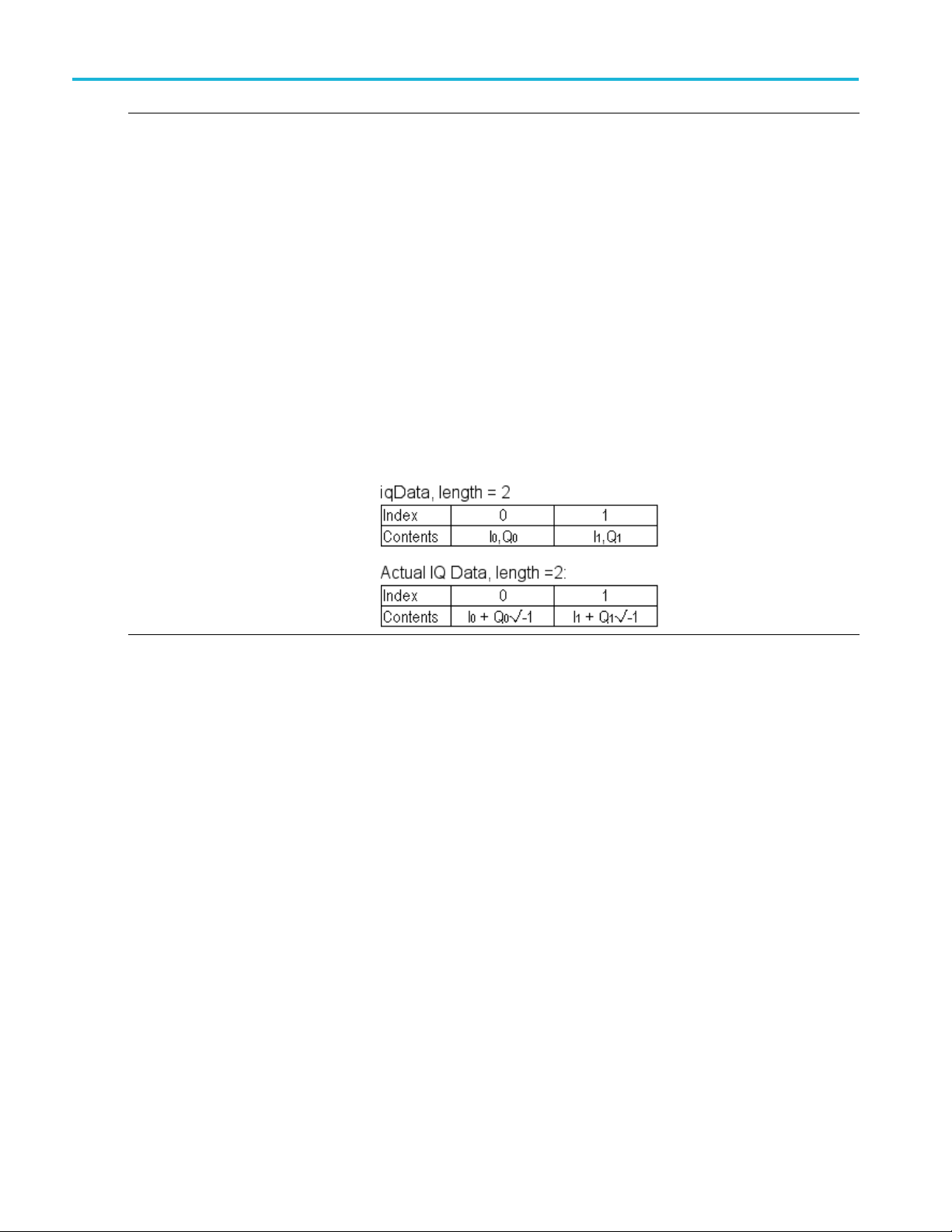
IQ block functio
ns
IQBLK_GetIQDa
Declaration:
Parameters:
iqData:
outLength:
reqLength:
Return Values:
noError:
errorDa
nal Detail:
Additio
taCplx
taNotReady:
Retrieves an IQ
ReturnStatus
reqLength);
Pointer to an
completes.
Pointer to an integer variable. Returns the actual number of complex IQ
samples returned in iqData buffer.
Number of IQ samples requested to be returned in iqData. The
maximum va
IQBLK_SetIQRecordLength(). Smaller values of reqlLength allow retrieving
partial IQ records.
The IQ record length has been queried.
There is not enough IQ data acquired to fill the IQ data record length.
When complete, the iqData array is filled with I-data and Q-data.
See the following illustration.
block data record in Cplx32 array format.
IQBLK_GetIQDataCplx(Cplx32* iqData, int* outLength, int
array of Cplx32 structs. Contains the IQ data when the function
lue of reqLength is equal to the recordLength value set in
58 API Reference
Page 65

IQ block functio
ns
IQBLK_GetIQDa
Declaration:
Parameters:
iData:
qData:
outLength:
reqLength:
Return Values:
noError
errorDa
onal Detail:
Additi
taDeinterleaved
:
taNotReady:
Retrieves an IQ
ReturnStatus
outLength, int reqLength);
Pointer to a fl
Pointer to a
The Q-data is not imaginary.
Pointer to an integer variable. Returns the actual number of I and Q sample
values returned in iData and qData buffers.
Number of IQ samples requested to be returned in iData and qData. The
maximum v
IQBLK_SetIQRecordLength(). Smaller values of reqlLength allow retrieving
partial IQ records.
The IQ record length has been queried.
There is not enough IQ data acquired to fill the IQ data record length.
When complete, the iData array is filled with I- data and the qData array is filled
with Q-data. The Q-data is not imaginary with Q-data.
e following illustration.
See th
block data record in separate I and Q array format.
IQBLK_GetIQDataDeinterleaved(float* iData, float* qData, int*
oat. Contains an array of I-data when the function completes.
float. Contains an array of Q-data when the function completes.
alue of reqLength is equal to the recordLength value set in
IQBLK_GetIQRecordLength Queries the IQ record length.
Declaration:
Parameters:
recordLength:
Return Values:
noError:
errorNotConnected:
Additional Detail: The value is stored in the recordLength parameter.
API Reference 59
ReturnStatus IQBLK_GetIQRecordLength(int* recordLength);
Pointer to an integer variable. Contains the number of IQ data samples to be
generated with each acquisition.
Range: 2 – 104.8576 M samples.
The IQ record length has been queried.
The device is not connected.
Page 66

IQ block functio
ns
IQBLK_GetIQSa
Declaration:
Parameters:
Return Values:
Additional Detail:
IQBLK_GetMaxIQBandwidth Queries the maximum bandwidth value.
Declaration:
Parameters:
Return Values:
Additional Detail: The value is stored in the maxBandwidth parameter.
mpleRate
iqSamplingRate: Pointer to a double. Contains the IQ sampling frequency when the function
noError:
maxBand
noErro
errorN
width:
r:
otConnected:
Queries the IQ s
ReturnStatus
completes.
The IQ sampling frequency was successfully queried.
The IQ Sample Rate value depends on the IQ Bandwidth value set by
IQBLK_Set
the sample rate.
ReturnStatus IQBLK_GetMaxIQBandwidth(double* maxBandwidth);
Pointer to a double. It contains the maximum bandwidth value when the function
completes.
The max
The device is not connected.
ample rate value.
IQBLK_GetIQSampleRate(double* iqSampleRate);
IQBandwidth() function. Set the bandwidth value before querying
imum bandwidth value has been queried.
_GetMaxIQRecordLength
IQBLK
ration:
Decla
meters:
Para
F:
maxC
urn Values:
Ret
noError:
Additional Detail:
es the maximum number of IQ samples which can be generated in one
Queri
IQ block record.
ReturnStatus IQBLK_GetMaxIQRecordLength(int* maxSamples);
ter to an integer. Contains the maximum IQ record length value when
Poin
the function c o m pletes.
e maxSamples value has been queried.
Th
e Maximum IQ Record Length value varies as a function of the IQ Bandwidth
Th
value set by the IQBLK_SetIQBandwidth() function. Set the bandwidth value
before querying the maximum length value. If the IQ Bandwidth setting is
hanged, this function must be called again to get the new maximum length
c
value. You should not request more than the maximum number of IQ samples
when calling IQBLK_SetIQRecordLength().
Q block processing can acquire up to 2 seconds of continuous signal data for
I
generating IQ records. The maximum record length value is the maximum
number of IQ sample pairs that can be generated at the requested IQ Bandwidth
and corresponding IQ Sample rate from 2 seconds of acquired signal data.
60 API Reference
Page 67

IQ block functio
ns
IQBLK_GetMinI
Declaration:
Parameters:
Return Values:
Additiona
IQBLK_SetIQBandwidth Sets the IQ bandwidth value.
Declarati
Paramete
Return V
Additional Detail:
QBandwidth
minBandwidth:
noError: The minimum bandwidth value has been queried.
errorNotConnected:
l Detail:
on:
rs:
iqBandwidth:
alues:
noError:
otConnected:
errorN
errorParameter: The iqBandwidth parameter value is outside the allowed range.
Queries the min
ReturnStatus
Pointer to a double. Contains the minimum bandwidth value when the function
completes.
The device i
The value i
ReturnStatus IQBLK_SetIQBandwidth(double iqBandwidth);
IQ bandw
Range: Query the Min and Max IQ BW values for range.
The IQ b
The device is not connected.
The IQ bandwidth must be set before the IQBLK_AcquireIQData() function
led.
is cal
If the iqBandwidth value is outside the allowed Min/Max range, the actual value
is set to the closest allowed value, and errorParameter status is returned. The
al value can be queried using IQBLK_GetIQBandwidth().
actu
imum bandwidth value.
IQBLK_GetMinIQBandwidth(double* minBandwidth);
s not connected.
s stored in the minBandwidth parameter.
idth value measured in Hz.
andwidth value has been set.
IQBLK_SetIQRecordLength Sets the number of IQ data samples to be generated by each IQ block
acquisition.
Declaration:
Parameters:
cordLength:
re
Return Values:
noError:
errorNotConnected:
ReturnStatus IQBLK_SetIQRecordLength(int recordLength);
IQ record length. This value is measured in samples.
Range: 2 — Max IQ record length. Query IQBLK_GetMaxIQRecordLength
r value.
fo
The IQ record length value has been set.
The device is not connected.
API Reference 61
Page 68

IQ block functio
ns
IQBLK_WaitFor
Declaration:
Parameters:
timeoutMsec: Timeout value measured in ms.
ready:
Return Values:
noError:
IQDataReady
Waits for the da
ReturnStatus
Pointer to a bool. Its value determines the status of the data.
True indicates the data is ready for acquisition. False indicates the data is not
ready and th
The function has executed successfully.
ta to be ready to be queried.
IQBLK_WaitForIQDataReady(int timeoutMsec, bool* ready);
e timeout value is exceeded.
62 API Reference
Page 69

IQ streaming fun
ctions
IQ streaming f
NOTE. IQ Streaming places a heavy load on the PC CPU when active. Other processing functions such as DPx Spectrum,
Audio, IQ Block, or intensive client processing may overload the CPU processing capacity if run concurrently with IQ
Streaming, pa
A high-performance CPU with 4 physical cores is recommended for best performance.
While streaming IQ data is being generated, any modification to the device hardware configuration, including Center
Frequency, Reference Level, Preamp, or Attenuation settings, will result in incorrect, uncalibrated data being generated
starting at
Stop state before changing these parameters.
IQSTREAM_
Declaration:
Parameters:
Return Values:
Additional Detail:
rticularly on lower performance CPUs. CPU overload may result in gaps or dropouts in the streamed IQ data.
the point where the new setting value i s applied. Streaming should be stopped and the device placed in a
GetMaxAcqBandwidth
maxBandwidthHz:
noError:
unctions
Queries th
ReturnSta
Pointer to a double variable. Returns the maximum IQ bandwidth supported
by IQ stre
The function completed successfully.
The bandwidth value set in IQSTREAM_SetAcqBawndwidth() should be no
larger
e maximum IQ Bandwidth for IQ streaming.
tus IQSTREAM_GetMaxAcqBandwidth(double* maxBandwidthHz);
aming.
than the value maxBandwidthHz returned by this function.
IQSTREAM_GetMinAcqBandwidth Queries the minimum IQ Bandwidth for IQ streaming.
ration:
Decla
eters:
Param
minBandwidthHz:
rn Values:
Retu
noError:
Additional Detail:
IQSTREAM_ClearAcqStatus Resets the “sticky” status bits of the acqStatus info element during an IQ
Declaration:
Parameters:
noError:
Return Values:
none:
Additional Detail:
ReturnStatus IQSTREAM_GetMinAcqBandwidth(double* minBandwidthHz);
ter to a double variable. Returns the minimum IQ bandwidth supported
Poin
by IQ streaming.
function completed successfully.
The
bandwidth value set in IQSTREAM_SetAcqBawndwidth() should be no
The
smaller than the value minBandwidthHz returned by this function.
reaming run interval.
St
id IQSTREAM_ClearAcqStatus();
vo
The function completed successfully.
This is affective for both client and file destination runs.
API Reference 63
Page 70

IQ streaming fun
ctions
IQSTREAM_GetA
Declaration:
Parameters:
bwHz_act:
srSps: Pointer to a double. Returns actual sample rate of IQ Streaming output data, in
Return Values:
noError:
Additional Detail:
cqParameters
Reports the pro
resulting from the users requested bandwidth.
ReturnStatus IQSTREAM_GetAcqParameters(double* bwHz_act, double*
srSps);
Pointer to a double. Returns actual acquisition bandwidth of IQ Streaming
output data in Hz.
Samples/se
The query was successful.
Call this function after calling IQSTREAM_SetAcqBandwidth() to set the
requeste
details of how requested bandwidth is used to select output bandwidth and
sample rate settings.
cessing parameters of IQ output bandwidth and sample rate
c
d bandwidth. See IQSTREAM_SetAcqBandwidth() description for
64 API Reference
Page 71

IQ streaming fun
ctions
IQSTREAM_GetD
Declaration:
Parameters:
fileinfo: Pointer to a struct. Returns a structure of information about the file output
Return Values:
noError:
Additional Detail:
iskFileInfo
Returns an info
ReturnStatus
operation.
The query was successful.
This information is intended to be queried after the file output operation has
completed
of the results may not be valid at that time.
IQSTRMFILEINFO structure content:
Item Description
numberSamples Number of IQ sample pairs written to the file.
sample0
triggerSampleIndex Sample index where the trigger event occurred.
triggerTimestamp
filenames Ptrs-to-wchar_t strings of the filenames of the
rmation structure about the previous file output operation.
IQSTREAM_GetDiskFileInfo(IQSTRMFILEINFO* fileinfo);
. It can be queried during file writing as an ongoing status, but some
Timestamp
Timestamp of the first sample written to file.
This is only valid if triggering has been enabled.
Set to 0
Times
triggering has been enabled. Set to 0 otherwise.
output files:
If data and header output are in the same file, the
strings will be identical. The string storage is in an
int
the function.
otherwise.
tamp of the trigger event. This is only valid if
ames[IQSTRM_FILENAME_DATA_IDX]:
filen
data filename
filename[IQSTRM_FILENAME_HEADER_ID-
eader filename
X]: h
ernal static buffer, overwritten with each call to
API Reference 65
Page 72

IQ streaming fun
ctions
acqStatus Acquisition s
Individual bits are used as indicators as follows:
NOTE: Bits0-15 indicate status for each internal
write block, s
indicate the entire run status up to the time of
query.
Individual Internal Write Block status
(Bits0-15, starting from LSB):
Bit0: 1=Inp
Bit1: 1=USB data stream discontinuity
Bit2: 1=Input buffer>75% full (IQStream
processing
Bit3: 1=Input buffer overflow (IQStream
processing overloaded, data loss has
occurred)
Bit4: 1 =Output buffer>75% full (File output
falling behind writing data)
Bit5: 1=O
slow, data loss has occurred)
Bit6-Bit15: (unused, always 0)
Entire run summary status (“sticky bits”)
The bits
as Bits0-15, except once they are set (->1) they
remain set for the entire run interval. They can
be used t
occurred at any time during the run.
(Bits16-31, starting from LSB):
Bit16:
Bit17: 1=USB data stream discontinuity
Bit18: 1=Input buffer>75% full (IQStream
proce
Bit19: 1=Input buffer overflow (IQStream
processing overloaded, data loss has occurred)
Bit20
falling behind data generation)
Bit21: 1=Output buffer overflow (File writing
too s
Bit22-Bit31: (unused, always 0)
IQSTREAM_ClearAcqStatus can be called to clear the “sticky” bits during the
run if it is desired to reset them.
tatus flags for the run interval.
o may not be very useful. Bits 16-31
ut overrange
heavily loaded)
utput buffer overflow (File output too
in this range are essentially the same
o determine if any of the status events
1=Input overrange
ssing heavily loaded)
: 1=Output buffer>75% full (File writing
low, data loss has occurred)
E. If acqStatus indicators show “Output buffer overflow”, it is likely that
NOT
the disk is too slow to keep up with writing the data generated by IQ S tream
processing. Use a faster disk (SSD recommended), or a smaller Acq BW which
erates data at a lower rate.
gen
66 API Reference
Page 73

IQ streaming fun
ctions
IQSTREAM_GetD
Declaration:
Parameters:
isComplete: Pointer to a b
isWriting:
Return Values:
noError:
Additiona
l Detail:
iskFileWriteStatus
Allows monitor
ReturnStatus
*isWriting);
Pointer to a
to file (useful when triggering is in use). (Input NULL if no return value is
desired).
The query was successful.
The returned values indicate when the file output has started and completed.
These become valid after IQSTR EAM_Start() is invoked, with any file output
destinat
isComplete:
isWriting:
For untriggered configuration, isComplete is all that needs to be monitored.
When it
“infinite” file length is selected (file length parameter msec=0), isComplete only
changes to true when the run is stopped with IQSTREAM_Stop().
If triggering is used, isWriting can be used to determine when a trigger has been
ved. The client application can monitor isWriting, and if a maximum wait
recei
period has elapsed while it is still false, the output operation can be aborted.
isWriting behaves the same for both finite and infinite file length settings.
ndicators sequence is as follows (assumes a finite file length setting):
The i
Untriggered operation:
IQSTREAM_Start()
Triggered operation:
IQS
ing the progress of file output.
IQSTREAM_GetDiskFileWriteStatus(bool* isComplete, bool
ool. Returns whether the IQ Stream file output writing complete.
bool. Returns whether the IQ Stream processing has started writing
ion selected.
false: indicates that file output is not complete.
dicates file output is complete.
true: in
false: indicates file writing is not in progress.
ndicates file writing is in progress. When untriggered, this value is
true: i
true immediately after Start() is invoked.
switches from false->true, file output has completed. Note that if
ile output in progress: [isComplete =false, isWriting =true]
=> F
=> File output complete: [isComplete =true, isWriting =true]
TREAM_Start()
=> Waiting for trigger, File writing not started: [isComplete=false,
isWriting =false]
Trigger event detected, File writing in progress: [isComplete=false,
=>
isWriting =true]
=> File output complete: [isCompl e te=tr ue, isWriting =true]
API Reference 67
Page 74

IQ streaming fun
ctions
IQSTREAM_GetE
Declaration:
Parameters:
enabled:
Return Valu
noError:
IQSTREAM_GetIQData Allows the client application to retrieve IQ data blocks generated by the IQ
Declaration:
Parameters:
iqdata:
iqlen:
iqinfo: Pointer to a struct. Returns a structure containing information about the IQ data
Return Values:
noError:
Additional Detail:
nable
es:
This function r
ReturnStatus
Pointer to a bool. Returns the current IQ Stream processing enable status.
True indicat
processing is inactive.
The query w a
Stream processing.
ReturnStatus IQSTREAM_GetIQData(void* iqdata, int* iqlen, IQSTRMIQINFO*
iqinfo);
Pointer to iqbuffer. Returns IQ sample data block.
Pointer to an integer. Returns the number of IQ data pairs returned in iqbuffer. 0
indicates no data available.
block. (Set value to NULL if the info struct is not wanted).
The query was successful.
Allows the client application to retrieve IQ data blocks generated by the IQ
Stream processing. Data blocks are copied out to the buffer pointed to by
iqdata, which must be allocated by the client large enough to hold the output
record. See IQSTREAM_GetIQDataBufferSize() to get the required buffer size.
The underlying data buffer organization is interleaved I/Q data pairs of the
data type configured. It is recommended to use the correct “complex” data
type: Cplx32 (Single data type), CplxInt32 (Int32), CplxInt16 (Int16) to simplify
accessing the data, although any buffer pointer type will be accepted.
iqlen returns the number of IQ sample pairs copied out to the buffer. The
returned value is 0 if no data is available. The client can poll the function, waiting
for iqlen>0 to indicate data is available. If possible, the client should not do this
in a “tight loop” to avoid heavily loading the processor while waiting for data.
IMPORTANT: Client applications must retrieve the data blocks at a fast enough
rate to avoid backing up a large amount of data within the API, which can
result in loss of data. The minimum retrieval rate can be calculated as (srSps
/maxSize). For example, with a sample rate of 56 Msps (40 MHz Acq BW)
and IQ block maxSize of 131,072 samples (default), blocks must be retrieved
at an average rate of no less than 56e6/131072 = 428 blocks/sec, or less than
2.34 msecs/block. The interval can be increased by requesting larger blocks
sizes, or decreased if desired.
IQ Streaming processing has an internal buffer which can hold up to 500 msec
of output IQ samples to allow the client to occasionally take longer than the
average required output rate. But if the client output retrieval rate continually
averages less than the required rate, the buffer will eventually overflow and
data will be lost.
eturns the current IQ Stream processing state.
IQSTREAM_GetEnable(bool* enabled);
es IQ Stream processing is active. False indicates IQ Stream
s successful.
68 API Reference
Page 75

IQ streaming fun
ctions
iqinfo return
s a copy of an IQSTRMIQINFO structure with the following content:
Item Description
timestamp
triggerIndices
triggerIndices
scaleFactor
Timestamp of first sample of block.
Number of trigger events occurring during block.
Maximum of 10
List of samp
triggerCount in length. This list is stored in an
internal static buffer and is overwritten on each call to
IQSTREAM_
client must copy the values to an external buffer before
the next call.
Scale factor to convert Int16 or Int32 data types to
standard
Single data type since those values are already scaled
to voltage.
0 trigger events per block.
le indices where trigger(s) occurred,
GetIQData(). To preserve it longer, the
voltage values. This value is set to 1.0 for
API Reference 69
Page 76

IQ streaming fun
ctions
acqStatus Acquisition s
interval. Individual bits are used as indicators as
follows:
Individual Re
from LSB):
Bit0: 1=Input overrange
Bit1: 1=USB d
Bit2: 1=Input buffer>75% full (IQStream processing
heavily loaded)
Bit3: 1=Inp
overloaded, data loss has occurred)
Bit4: 1=Output buffer>75% full (Client falling
behind unlo
Bit5: 1=Output buffer overflow (Client unloading
data too slow, data loss has occurred)
Bit6-Bit1
Entire run summary status (“sticky bits”)
The bits in this range are essentially the same as
Bits0-15
set for the entire run interval. They can be used to
determine if any of the status events occurred at any
time duri
Bit16: 1=Input overrange
Bit17: 1=USB data stream discontinuity
Bit18: 1
processing heavily loaded)
Bit19: 1=Input buffer overflow (IQStream
proces
Bit20: 1=Output buffer>75% full (Client falling
behind unloading data)
Bit21:
data too slow, data loss has occurred)
Bit22-Bit31: (unused, always 0)
IQSTREAM_ClearAcqStatus can be called to clear the “sticky” bits during the
it is desired to reset them.
run if
tatus flags for this block and entire run
trieved Block status (Bits 0-15, starting
ata stream discontinuity
ut buffer overflow (IQStream processing
ading data)
5: (unused, always 0)
, except once they are set (->1) they remain
ng the run. (Bits16-31, starting from LSB):
=Input buffer>75% full (IQStream
sing overloaded, data loss has occurred)
1=Output buffer overflow (Client unloading
70 API Reference
Page 77

IQ streaming fun
ctions
IQSTREAM_GetI
Declaration:
Parameters:
maxSize: Pointer to an
Return Valu
noError:
Additional Detail:
QDataBufferSize
es:
Returns the max
IQSTREAM_GetIQData () function.
ReturnStatus IQSTREAM_GetIQDataBufferSize(int* maxSize);
when using client IQ access. Size value is in IQ sample pairs.
The query w a
This funct
directly from the IQ Streaming processing.The client application should
call this function to query the buffer size (maxSize IQ samples) required
to return
calling this function the client should request a buffer size by using the
IQSTREAM_SetIQDataBufferSize() function. See that function description for
details o
The IQSTREAM_SetAcqBandwidth() function should be called to set the
requested IQ bandwidth before setting or querying the IQ Buffer size values.
The clie
IQ data pairs. Example buffer allocation sizes for different types of output data
are given below.
Exam
is acceptable):
Example client function use:
n how the actual buffer size is determined.
nt application should allocate a buffer large enough to accept maxSize
Data Type
Singl
Int32
Int16
ple C language client buffer allocation code (using either malloc() or new
Single: Cplx32* pCplx32 = new Cplx32[maxSize];
32: CplxInt32* pCplxInt32 = malloc(maxSize*sizeof(CplxInt32));
Int
Int16: CplxInt16* pCplxInt16 = malloc(maxSize*sizeof(CplxInt16));
t maxSize;
in
IQSTREAM_SetIQDataBufferSize (500000); // request 500,000 IQ sample
per block pairs
STREAM_GetIQDataBufferSize (&maxSize); // maxSize = 262144
IQ
returned
Cplx32* pIQdata = new Cplx32[maxSize];
QSTREAM_GetIQData(pIQdata, &iqlen, &iqinfo);
I
imum number of IQ sample pairs which will be returned by the
integer. Returns maximum size IQ output data buffer required
s successful.
ion is only applicable for a client application that receives IQ data
the IQ data from the IQSTREAM_GetIQData() function. Before
IQ Buffer data type Required Client B uffer
size
e
Cplx3
CplxI
Cplx
2
nt32
Int16
ze * size(Cplx32)
maxSi
ze * size(CplxInt32)
maxSi
ize * size(CplxInt16)
maxS
API Reference 71
Page 78

IQ streaming fun
ctions
IQSTREAM_SetA
Declaration:
Parameters:
bwHz_req:
Return Values:
noError: The requested value was accepted.
errorIQStreamBandwidthOutOfRange:
errorNotConnected:
Additional Detail:
cqBandwidth
Sets the user’s
stream samples.
ReturnStatus IQSTREAM_SetAcqBandwidth(double bwHz_req);
Requested ac
The requested value is out of the legal bandwidth range. The output bandwidth
has been set to the closest legal bandwidth.
The device is not connected.
The following table shows the mapping of Requested Bandwidth to Output
sample ra
NOTE. The Requested Bandwidth setting should only be changed when the
instrument is in the global Stopped state. The new BW setting does not take
ntil the global system state is cycled from Stopped to Running.
effect u
20.0 MHz < BW ≤ 40.0 MHz
10.0 MHz < BW ≤ 20.0 MHz
5MHz<BW≤ 10 MHz
2.50 MHz < BW ≤ 5.0 MHz
1.25 MHz < BW ≤ 2.50 MHz
625.0 kHz < BW ≤ 1.25 MHz
312.50 kHz < BW ≤ 625.0 kHz
156.250 kHz < BW ≤ 312.50 kHz
78125.0 Hz < BW ≤ 156.250 kHz
39062.5 Hz < BW ≤ 78125.0 Hz
19531.25 Hz < BW ≤ 39062.5 Hz
9765.625 Hz < BW ≤ 19531.25 Hz
BW ≤ 9765.625 Hz
The range of Requested Bandwidth values can be queried using
IQSTREAM_GetMaxAcqBandwidth() and IQSTREAM_GetMinAcqBandwidth().
request for the acquisition bandwidth of the output IQ data
quisition bandwidth of IQ Streaming output data, in Hz.
te for all legal bandwidth settings.
Requested BW
Output s
MSa/s
56.000
0MSa/s
28.00
0MSa/s
14.00
0 MSa/s
7.00
0 MSa/s
3.50
50 MSa/s
1.7
.000 kSa/s
875
7.500 kSa/s
43
18.750 kSa/s
2
09.375 kSa/s
1
54687.5 Sa/s
24373.75 Sa/s
13671.875 Sa/s
ample rate
72 API Reference
Page 79

IQ streaming fun
ctions
IQSTREAM_SetD
Declaration:
Parameters:
Return Values:
Additional Detail:
Sets the base filename for file output can be accomplished with similar functions. These functions are grouped together.
IQSTREAM_SetDiskFilenameBase Sets the base filename for file output (char string)
Declar
IQSTREAM_SetDiskFilenameBaseW Sets the base filename for file output (wchar_t string)
Decla
Param
Return Values:
dditional Detail:
A
iskFileLength
msec:
noError: The setting
ation:
ration:
eters:
ameBase:
filen
nameBaseW:
file
noError: The setting was accepted.
Sets the time le
ReturnStatus
Length of time in milliseconds to record IQ samples to file.
See IQSTREA
status to determine when it is active and completed.
msec value File store
0
>0
ReturnStatus IQSTREAM_SetDiskFilenameBase(const char* filenameBase);
QSTREAM_SetDiskFilenameBaseW(const wchar_t* filenameBaseW)
filename for file output. This can include drive/path, as well as the common
Base
base filename portion of the file. The filename base should not include a file
extension, as the file writing operation will automatically append the appropriate
for the selected file format.
one
e filename for file output. This can include drive/path, as well as the common
Bas
base filename portion of the file. The filename base should not include a file
extension, as the file writing operation will automatically append the appropriate
efortheselectedfile format.
on
The complete output filename has the following format:
<filenameBase><suffix><.ext>
filenameBase>: as set by this function
<
<suffix>: as s et by filename suffix control in IQSTREAM_SetDiskFilename-
Suffix()
<.ext>: as set by destination control in IQSTREAM_SetOutputConfigura-
tion(), [ .tiq, .siq, .siqh+.siqd]
If separate data and header files are generated, the same path/filename is used
for both, with different extensions to indicate the contents.
ngth of IQ data written to an output file.
IQSTREAM_SetDiskFileLength(int msec);
was accepted.
M_GetDiskFileWriteStatus to find how to monitor file output
behavior
No time lim
when IQSTREAM_Stop() is called.
File output ends after this number of milliseconds of
samples stored. File storage can be terminated early by
calling
it on file output. File storage is terminated
IQSTREAM_Stop().
API Reference 73
Page 80

IQ streaming fun
ctions
IQSTREAM_SetD
Declaration:
Parameters:
suffixCtl: Sets the filen
Return Values:
noError: The setting was accepted.
Additional
iskFilenameSuffix
Detail:
Sets the contro
output base filename.
ReturnStatus IQSTREAM_SetDiskFilenameSuffix(int suffixCtl);
See description of IQSTREAM_SetDiskFilename() for the full fi lename format.
suffixCtl value Suffix generated
IQSSDFN_SUFFIX_NONE
(-2)
IQSSDFN_SUFFIX_TIMESTAMP
(-1)
≥ 0 5 digi
l that determines what, if any, filename suffix is appended to the
ame suffix control value.
None. Base filename is used without
suffix. (Note that the output filename
will not c
one run to the next, so each output file
will overwrite the previous one unless
the filen
calling the Set function again.)
String formed from file creation time
Format:
“-YYYY
(Note this time is not directly linked
to the data timestamps, so it should
not be
timestamp of the file data!)
value = suffixCtl.
Format: “ -nnnnn”
(Not
each time IQSTREAM_Start() is
invoked with file data destination
sett
hange automatically from
ame is explicitly changed by
.MM.DD.hh.mm.ss.msec”
used as a high-accuracy
t auto-incrementing index, initial
e index auto-increments by 1
ing.)
74 API Reference
Page 81

IQ streaming fun
ctions
Following are
settings. Multiple filenames show suffix auto-generation behavior with each
IQSTREAM_Start. The most recent suffixCtl setting remain in effect until changed
by another fun
(Assume <filenameBase> is “myfile” and TIQ file format is selected.)
suffixCtl value Full Filenam e (and behavior with
IQSSDFN_SUFFIX_NONE “myfile.tiq”
IQSSDFN_SUFFIX_TIMESTAMP “myfile-2015.04.15.09.33.12.522.tiq”
10
4
examples of output filenames generated with different suffixCtl
ction call.
multiple runs)
“myfile.tiq
“myfile.tiq”
…
“myfile-2
“myfile-2015.04.15.09.33.17.301.tiq”
…
“myfile-00010.tiq”
“myfile“myfile-00012.tiq”
…
“myfile-00004.tiq”
“myfile
…
”
015.04.15.09.33.14.697.tiq”
00011.tiq”
-00005.tiq”
API Reference 75
Page 82

IQ streaming fun
ctions
IQSTREAM_SetI
Declaration:
Parameters:
reqSize: Requested size of IQ output data buffer in IQ sample pairs. 0 resets to default.
Return Values:
noError: The value wa
Additional Detail:
QDataBufferSize
Sets the reques
ReturnStatus
This functi
directly from the IQ Streaming processing. The client application should call
this function to request an output block size (reqSize IQ samples) for IQ data
returned f
size, the client should call IQSTREAM_GetIQDataBufferSize() to retrieve the
actual buffer size, and allocate an appropriate sized memory buffer.
Availabl
value, with the base size set by the requested IQ bandwidth. The client's
requested size will be converted to the closest smaller available size which
can be pro
the buffer size to the default size, and requested size of 1 sets the buffer to
minimum size. A requested size of 1,000,000 will set to the maximum size.
The IQST
requested IQ bandwidth before setting or querying the IQ Buffer size values.
The following table gives the base buffer size (in IQ samples) as a function
of IQ Ba
IQ BW ra
2.5 MHz < BW ≤ 40 MHz 65536
(1.25/d) MHz < BW ≤ (2.5/d) MHz 32768/d
BW ≤ 9765.625 Hz 128
Other buffer size values can be calculated from BaseSize as follows:
MinimumSize = 1*BaseSize
Max
DefaultSize = 2*BaseSize
ted size in IQ sample pairs of the IQ record returned to the client.
IQSTREAM_SetIQDataBufferSize(int reqSize);
s accepted.
on is only applicable for a client application that receives IQ data
rom the IQSTREAM_G etIQData() function. After setting the requested
e buffer sizes are limited to integer multiples (1,2,..,8) of a base size
vided at the requested IQ bandwidth. A requested size of 0 resets
REAM_SetAcqBandwidth() function should be called to set the
ndwidth.
nge
imumSize = 8*BaseSize
BaseSi
2,4,8,...,128)
(d=1,
ze
76 API Reference
Page 83

IQ streaming fun
ctions
IQSTREAM_SetO
Declaration:
Parameters:
dest:
dtype:
turn Values:
Re
noError: The requested settings were accepted.
errorIQStreamInvalidFile-
ataType:
D
Additional Detail:
utputConfiguration
Sets the output
ReturnStatus
IQSOUTDTYPE dtype);
Destination
dest value Destination
IQSOD_CLIENT(0) Client application
IQSOD_FILE_TIQ(1) TIQ format file (.tiq extension)
IQSOD_FILE_SIQ(2) SIQ format file with header and data
IQSOD_FI
IQSOD_FILE_MIDAS (11) Midas 2.0 (Platinum) format file,
IQSOD_
(12)
Output IQ data type. Valid settings:
dtype value Data type
IQSODT_SINGLE(0) 32-bit single precision floating point (not
IQSODT_INT32(1)
IQSODT_INT16(2)
IQSODT_SIN-
E_SCALE_INT32 (3)
GL
Invalid selection of TIQ file and Single data type together.
The destination can be the client application, or files of different formats. The IQ
data type can be chosen independently of the file format. IQ data values are
stored in interleaved I/Q/I/Q order regardless of the destination or data type.
data destination and IQ data type.
IQSTREAM_SetOutputConfiguration(IQSOUTDEST dest,
(sink) for IQ sample output. Valid settings:
n one file (.siq extension)
t with header and data in
on)
.0 (Platinum) format files,
LE_SIQ_SPLIT(3)
FILE_MIDAS_DET
combined i
SIQ forma
separate files (.siqh and .siqd extensions)
combined header and data (.cdif
extensi
Midas 2
separate header and detachad data
(.cdif and .det extensions)
valid with TIQ file destination)
32-bit integer
16-bit integer
32-bit single precision float, with data
aled the same as Int32 data type (not
sc
valid with TIQ file destination)
NOTE. TIQ format files only allow Int32 or Int16 data types.
API Reference 77
Page 84

IQ streaming fun
ctions
IQSTREAM_Star
Declaration:
Parameters:
Return Values:
Additional Detail:
IQSTREAM_Stop This function terminates IQ Stream processing and disables data output.
Declaration:
Parameters:
Return Values:
Additional Detail:
t
(none):
noError:
errorBufferAllocFailed: Internal buffer allocation failed (memory unavailable)
errorIQStreamFileOpenFailed:
(none):
noError:
Initializes IQ
ReturnStatus
The operation was successful
Output file open (create) failed.
If the data destination is the client application, data will become available soon
after the
begin flowing to the client without need for a trigger event. The client must begin
retrieving data as soon after Start() as possible.
If the da
enabled,datastartstobewrittentothefile immediately. If triggering is enabled,
datawillnotstarttobewrittentothefile until a trigger event is detected.
TRIG_Fo
one does not occur.
ReturnStatus IQSTREAM_Stop();
The operation was successful.
If the data destination i s file, file writing is stopped and the output file is closed.
Stream processing and initiates data output.
IQSTREAM_Start();
Start() function is invoked. Even if triggering is enabled, the data will
ta destination is file, the output file is created, and if triggering is not
rceTrigger() can be used to generate a trigger event if the specified
IQSTREAM_WaitForIQDataReady Block while waiting for IQ Stream data output.
Declaratio
Parameter
Return Values:
Additional Detail:
78 API Reference
n:
s:
timeoutMsec: Timeout interval in milliseconds.
ready:
noError:
errorIQStreamingNotEnabled:
ReturnStatus IQSTREAM_WaitForIQDataReady(int timeoutMsec, bool* ready)
Ptr to boolean to return ready status. Returns true if data is ready, false if data
is not rea
The operation was successful.
IQ streaming processing not enabled.
This fu
the next block of IQ data. If data becomes av ailable during the timeout interval,
the function returns immediately with the ready flag set to true. If the timeout
interv
to false. A timeout value of 0 checks for data ready, and returns immediately
without waiting.
dy.
nction blocks while waiting for the IQ Streaming processing to produce
al expires without data being ready, the function returns with the flag set
Page 85

IQ streaming fun
IQ Streaming SIQ/SIQH/SIQD File Fo rmats
IQ Streaming file outputs can be configured as IQSOD_FILE_SIQ or IQSOD_FILE_SIQ_SPLIT using the
IQSTREAM_SetOutputConfiguration function dest (destination) parameter. This section describes the SIQ/SIQH/SIQD
output files’ content and format.
If IQSOD_FILE_SIQ format is selected, a single file with extension .siq is generated, containing both header information and
sample data. If IQSOD_FILE_SIQ_SPLIT is selected, two files are generated: a text file containing the header information,
with extension .siqh; and binary data file with the sample data content, with extension .siqd.
The header information format is the same in both .siq and .siqh file. Likewise, the data content format is the same in the
.siq and .siqd files. The choice of combined or split files is a user preference, and does not affect the actual file c
When split files are selected, the filename portion of both files, excluding the extension, will be identical.
ontent.
ctions
Header Block. The Header consists of lines of 8-bit ASCII text characters, each line terminated by a LF/CR (0x0D/0x0A)
control character pair.
Example Header Block:
RSASIQHT:1024,1
FileDateTime:2015-04-29T10:12:33.170
Hardware:RSA306-Q000004
Software/Firmware:3.6.0034-V1.7-V1.1-V3
ReferenceLevel:0.00
CenterFrequency:100000000.00
SampleRate:56000000.00
AcqBandwidth:40000000.00
NumberSamples:56000
NumberFormat:IQ-Int16
API Reference 79
Page 86

IQ streaming fun
Header Identifier. The Header Identifier is always the first line of the header block. It is the only fixed location item in the
header section. In addition to the fixed H eader identifier string (RSASIQHT), it also contains the header size and version.
(Line1): RSASIQHT<:headerSizeInBytes>,<versionNumber>
Example: Header size: 1024 bytes, Version: 1
RSASIQHT:1024,1
In combined .siq files, the headerSizeInBytes value indicates the starting location (in bytes from the beginning of the file) of
the Data section. This value should always be read and used as an index to the Data, as it may vary from file to file. Not
all of the header may be needed for header content. Unused header range is filled with space characters (0x20) from the
last piece of useful header data to the end of the header itself. In .siqd files, data always starts with the first byte, so the
header size value should be ignored then.
ctions
DataScale:6.2660977E-005
DataEndian:Li
RecordUtcSec:001430327553.177054669
RecordUtcTime:2015-04-29T17:12:33.177054669
RecordLclTim
TriggerIndex:0
TriggerUtcSec:001430327553.177054669
TriggerUtcT
TriggerLclTime:2015-04-29T10:12:33.177054669
AcqStatus:0x00000000
RefTimeSour
FreqRefSource:Intern
ttle
e:2015-04-29T10:12:33.177054669
ime:2015-04-29T17:12:33.177054669
ce:System
The versionNumber is used to indicate different header content formats. Initially there is only one header format, version
number = 1. However, it may change in future SW releases, so should be verified when decoding header information.
Header Information. Following the Header Identifier are lines with parameters describing the associated Data block
.
values
ne has the format:
Each li
Dstring>:<InfoValueString>
<InfoI
ader Information entries may be in any order. The table below describes the Header information c ontent.
The He
Table 3 : IQ Streaming header content
Header Info Item: Header Info Value: Example:
FileDateTime:<fileDateTime>*
*<fileDateTime> value only indicates the time
the file was created. It is not an accurate
timestamp of the data stored in the file.
Hardware:<InstrNom>-<SerNum>
Software/Firmware:<Versions> <Versions>: (API_SW)-(USB_FW)-
<fileDateTime>: File creation
date and time. Format:
YYYY-MM-DDThh-hh-ss.msec
<InstrNom>: Instrument
Nomenclature
<SerNum>: Instrument Serial
number
(FPGA_FW)-(BoardID)
FileDateTime:2015-04-29T10:12:33.170
Hardware:RSA306-B010114
Software/Firmware:3.6.0034-V1.7V1.1-V3
80 API Reference
Page 87

Table 3: IQ Streaming header content (cont.)
Header Info Item: Header Info Value: Example:
IQ streaming fun
ctions
ReferenceLevel:<RefLeveldBm> <RefLeveldBm>: Instrument
Reference Level setting in dBm
CenterFrequency:<CFinHz> <CFinHz> Instrument Center
Frequency setting in Hertz
SampleRate:<SRinSamples/sec> <SRinSamples/sec>: Data sample
rate in samples/second
AcqBandwidth:<BWinHz>
NumberSamples:<numSamples> <numSamples>: Number of IQ
NumberFormat:<format> <format>: Data block s ample data
<BWinHz>: Acquisition (flat)
Bandwidth of Data in Hertz,
centered at 0 Hz (IQ baseband)
sample pairs stored in Data block
format:
IQ-Single: IQ pairs, each in one
Single precision float (4 bytes
per I or Q value)
IQ-Int32: IQ pairs, each in one
32-bit integer (4 bytes per I or
Q value)
IQ-Int16: IQ pairs, each in one
16-bit integer (2 bytes per I or
Q value)
ReferenceLevel:0.00
CenterFrequency:100000000.00
SampleRate:56000000.00
AcqBandwidth:40000000.00
NumberSamples:56000
NumberFormat:IQ-Int16
DataScale:<scaleFactor> <scaleFactor>: Scale factor to
convert In32 or Int16 I and Q values
into “volts into 50 ohms”
DataEndian:<endian> <endian>: Indicates Data block
values stored in Little or Big Endian
order
RecordUtcSec:<recordUtcSec> <recordUtcSec>: UTC Timestamp
of first IQ sample in Data block
record.
Format: seconds.nanoseconds
since Midnite, Jan 1, 1970 (UTC
time).
RecordUtcTime:<recordUtcTime>
<recordUtcTime>: UTC Timestamp
of first IQ sample in Data block
record. Format: YYYY-MMDDThh:mm:ss.nanoseconds (UTC
time).
DataScale:6.2660977E-005
DataEndian:Little
RecordUtcSec:001430327553.177054669
RecordUtcTime:2015-0429T17:12:33.177054669
API Reference 81
Page 88

IQ streaming fun
Table 3: IQ Streaming header content (cont.)
Header Info Item: Header Info Value: Example:
ctions
RecordLclTime:<recordLclTime> <recordLclTime>: Local Timestamp
of first IQ sample in Data block
record. Format: YYYY-MMDDThh:mm:ss.nanoseconds (Local
time).
TriggerIndex:<sampleIndex>
TriggerUtcSec:<triggerUtcSec> <triggerUtcSec>: UTC Timestamp
TriggerUtcTime:<triggerUtcTime>
TriggerLclTime:<triggerLclTime> <triggerLclTime>: Local Timestamp
<sampleIndex>: IQ Sample index
in Data block where trigger event
occurred. If triggering is not enabled,
sampleIndx is set to 0 (first sample
of record).
of trigger event. Format:
seconds.nanoseconds since
Midnite, Jan 1, 1970 (UTC time). If
triggering is not enabled, this value
is equal to RecordUtcSec.
<triggerUtcTime>: UTC Timestamp
of trigger event. Format: YYYYMM-DDThh:mm:ss.nanoseconds
(UTC time). If triggering is not
enabled, this value is equal to
RecordUtcTime.
of trigger event. Format: YYYY-MMDDThh:mm:ss.nanoseconds (Local
time). If triggering is not enabled,
this value is equal to RecordLclTime.
RecordLclTime:2015-0429T17:12:33.177054669
TriggerIndex:21733
TriggerUtcSec:001430327553.177054669
TriggerUtcTime:2015-0429T17:12:33.177054669
TriggerLclTime:2015-0429T17:12:33.177054669
AcqStatus:<acqStatusWord> <acqStatusWord>: Hexidecimal
value of acquisition and file status.
Individual bits in this word indicate
various status types. For detailed
description, see acqStatus item in
the IQSTREAM_GetDiskFileInfo()
function description.
A value of 0x00000000 indicates no
problems during file acquisition and
storage.
AcqStatus:0x00000000
82 API Reference
Page 89

Table 3: IQ Streaming header content (cont.)
Header Info Item: Header Info Value: Example:
IQ streaming fun
ctions
RefTimeSource:<refTimeSource> <refTimeSource>: Timing source
used to set API reference timing
system:
"System" : PC system tim e
"GnssRx" : Internal G NSS receiver
"UserCa" : User timing setting
FreqRefSource:<freqRefSource> <freqRefSource>: Frequency
reference source:
"Intern" : Internal reference
"Extern" : External reference input
"GnssRx" : Internal G NSS receiver
"UserCa" : User calibration setting
RefTimeSource:System
FreqRefSource:Intern
Data Block. Data block format is the same for all SIQx file selections. It consists of IQ sample pairs in alternating
I/Q orde
Each IQ
SampleRate parameter.
Each I and Q value is represented by a binary number in the data format specified by the header block NumberFormat
parameter (Single, Int32 or Int16), with “endian-ness” specified by the DataEndian parameter.
r as shown here:
0) I(1) Q(1) I(2) Q(2) …. I(N-2) Q(N-2) I(N-1) Q(N-1)
I(0) Q(
where N
equals the NumberSamples parameter value.
Sample pair forms a complex baseband time-domain sample, at the sample rate given by the header block
Int32 and Int16 I and Q samples values can be scaled to “volts into 50 ohms” form by multiplying each integer value by the
er block DataScale parameter value. Single values are prescaled to the correct form, so do not need to be multiplied by
head
the scale factor (it is set to 1.0 to indicate this).
API Reference 83
Page 90

Playback functi
ons (R3F file format)
Playback func
These functions pertain to the playback of files recorded with the RSA306, RSA306B, the RSA500A Series, and the
RSA600A Series. The instruments can record using two data structures, formatted or raw.
Recordings created using the formatted data structure create a single file (.r3f) that contain a single configuration info block,
followed by a block of data and status information. The file contains the ADC output from the digitizer with enough metadata
about the system state to reconstruct the IQ data stream.
Recordings created using the raw data structure create two files; a header file (.r3h) and a raw data file (.r3a).
The API can only play back files in the .r3f format.
PLAYBACK_OpenDiskFile Opens a .r3f file on disk and prepares the system for playback according to
Declaration:
Parameters:
filename: The Unicode name of an accessible disk file in .r3f format. The file must exist
startPercentage:
stopPercentage:
skipTimeBetweenFullAcquisitions:
tions (R3F file format)
the parameters passed.
ReturnStatus PLAYBACK_OpenDiskFile(const wchar_t * fileName, int
startPercentage, int stopPercentage, double skipTimeBetweenFullAcquisitions,
bool loopAtEndOfFile, bool emulateRealTime);
and you must have read permission to its contents.
Thestartinglocationinthefile from which to commence playback. Units are
in percent of the total file length. File playback will skip the portion of the file
prior to Start Position whenever it plays the file from the beginning, including
repeatedly skipping that portion of the file if loop mode is enabled.
Minimum allowed value: 0
Maximum allowed value: 99
Units: percentage
The stopping location in the file at which playback terminates. Units are in
percent of total file length. File playback will skip the portion of the file after Stop
Position to the end of the file, including skipping it every time the file plays if
loop mode is enabled.
Minimum allowed value: 1
Maximum allowed value: 100
Units: percentage
The amount of time to skip in the file in order to accomplish fast-forwarding.
The playback mechanism will play a contiguous slice of the file contents, the
size of which is determined by the needs of the active measurements. Once
that slice has been processed, file playback will skip a section of data roughly
corresponding to Skip time, then start processing a new slice. Please note that
skip time is not completely arbitrary – it is rounded up and discretized to the
nearest USB data frame boundary, approximately 73 µs.
Minimum allowed value: 0 (implies no portion of the file is skipped)
Maximum allowed value: undefined, determined by the actual length of
the input file.
Units: time in seconds, rounded up to the nearest ~73 µs unit.
84 API Reference
Page 91

Playback functi
ons (R3F file format)
loopAtEndOfF
emulateRealTime: This setting, when true, puts the system in a real time emulation mode. Data
Return V
Additional Detail:
alues:
noError:
errorS
ure:
errorStreamedFileInvalidHeader:
errorStreamingInvalidParam-
s:
eter
ile:
treamedFileOpenFail-
Controls if th
when the stop position is reached during playback.
Allowed values:
true (loop at e
received.
false (do not loop and end of file) terminates playback when the stop
position (or
is processe
device. A 60 second recording will take ~60 seconds to replay, and there is no
guarantee that every frame of data is processed by the system. This mode is
particular
When set to false, the system uses a deterministic playback method that
processes every frame o f data. Deterministic playback is significantly more time
consuming
of a file.
Be aware that real time emulation mode is dependent on sufficient hardware
processi
SSD drive is typically necessary) and for the data processing demands of the
streamed playback data.
Allowed v
playback.
The file
The file
non-zero length, or other issues which might interfere with its use.
The metadata stored in the file by the API appears to be corrupt. This data is
necessary for playback to match the circumstances under which it was captured.
One of the parameters passed to the function was out of range. Verify the
es and types of parameters.
rang
Once
behaves much as it would when connected to actual hardware.
e file playback automatically wraps around to the start position
nd of file) loops the file indefinitely until a stop request is
end of file) is reached.
d in a fashion indistinguishable from a live connection to an RSA
ly useful for replaying files that contain audio data that you wish to hear.
and should only be used for analyzing small significant portions
ng power in order to read the data at the full necessary data rate (an
alues: true for emulating real time playback, false for deterministic
successfully opened for playback.
could not be opened. Check the file for existence, access permissions,
playback has commenced (via a call to Run() or equivalent), the system
PLAYBACK_GetReplayComplete Determine if a file being replayed has reached the end of the file contents.
Declaration:
Parameters:
mplete:
co
Return Values:
noError:
API Reference 85
ReturnStatus PLAYBACK_GetReplayComplete(bool * complete);
Pointer to a boolean. True indicates file playback has completed. False
indicates it has not completed. Note that in loop back mode, a file will never
port true from a call to PLAYBACK_GetReplayComplete().
re
The operation completed successfully.
Page 92

Power functions
Power functio
POWER_GetSta
Declaration
Parameters:
powerInfo: Pointer to a
Return Values:
noError:
errorMonitoringNotSupported:
Additional Detail:
tus
:
ns
This command i
Queries the device power and battery status information.
ReturnStatus POWER_GetStatus(POWER_INFO* powerInfo);
power and battery status information. See Additional Detail below for structure
content.
The status has been successfully queried.
The devic
POWER_INFO structure content:
externalPowerPresent
(boolean):
batteryPresent
(boole
batte
(double):
batteryOverTemperature
(boolean):
batteryHardwareError
oolean):
(b
RSA600A Series devices can also return a result from this function. However,
since they do not have an internal battery, they will always report the following
tatus:
s
externalPowerPresent = true
batteryPresent = false
s for the RSA500A Series instruments only.
POWER_INFO struct. On return, the structure contains the current
e does not support battery monitoring.
True indicates an external power supply is
connected. False indicates no external power
is connected.
supply
True indicates a battery is installed in the
an):
ryChargeLevel
. False indicates no battery installed.
device
If batteryPresent is false, the following
battery-related status indicators are invalid and
d be ignored.
shoul
Indicates battery charge level in percent
fully discharged, 100.0=fully charged).
(0.0=
ng charge, the over temp alarm can be set
Duri
if the pack exceeds 45 °C. The charger should
stop charging when the alarm is set. If charging
n't stop, the pack will open a resettable
does
protection FET.
During discharge, the over temp alarm will set
he pack exceeds 60 °C. The pack will set
if t
the alarm bit, but if the temperature doesn't
decrease, the pack will open a resettable
otection FET and shut down the device.
pr
True indicates the battery controller has detected
error in the battery hardware. False indicates
an
the battery hardware is operating normally.
86 API Reference
Page 93

Spectrum functi
ons
Spectrum func
SPECTRUM_Acq
Declaration:
Return Values:
noError:
errorNotConnected:
Additional Detail:
SPECTRUM
Declaration:
Parameters:
enable:
Return
noError:
uireTrace
_GetEnable
Values:
tions
Initiates a spectrum trace acquisition
ReturnStatu
The function has completed successfully.
The device is not connected.
Executing this function initiates a spectrum trace acquisition. Before calling this
function,
Center Frequency, Reference Level, any desired Trigger conditions, and the
SPECTRUM configuration settings.
Queries t
ReturnSt
Pointer to a bool. Contains the enable status of the spectrum.
True ind
disabled.
The en
s SPECTRUM_AcquireTrace();
all acquisition parameters must be set to valid states. These include
he enable status.
atus SPECTRUM_GetEnable (bool* enable);
icates the spectrum measurement is enabled. False indicates it is
able status has been successfully queried.
API Reference 87
Page 94

Spectrum functi
ons
SPECTRUM_GetL
imits
Declaration:
Parameters:
limits: Return the spectrum setting limits.
Values:
Return
noError:
1
The maximum span is device dependent.
Queries the lim
ReturnStatus
Spectrum_Limits
its of the spectrum settings.
SPECTRUM_GetLimits(Spectrum_Limits *limits);
Description 64 bit API
limit
1
double maxSpan
Maximum
––
Span
double minSpan Minimum Span
double max
RBW
Maximum
1 kHz 100 kHz
10 MHz 10 MHz
RBW
double min
RBW
Minimum RB
double maxVBW Maximum
W
10 Hz 100 Hz
10 MHz 10 MHz
VBW
double minVBW Minimum VBW 1 Hz 100 Hz
double maxTraceLength Maximum
64001 64001
Trace Length
double minTraceLength Minimum
801 801
Trace Length
The maximum span is device dependent.
mits have been successfully queried.
The li
32 bit API
limit
1
––
88 API Reference
Page 95

Spectrum functi
ons
SPECTRUM_GetS
Declaration:
Parameters:
settings:
Return Values:
noError:
Additional Detail:
ettings
Queries the spe
ReturnStatus
Pointer to Spectrum settings.
Returns the c
Item Description
double span
double rbw Resolution bandwidth measured in
bool enableVBW Enables or disables VBW
double vbw Video band
int traceLength
Spectru
SpectrumVerticalUnits verticalUnit
double actualStartFreq Actual start frequency in Hz
double actualStopFreq Actual stop frequency in Hz
double actualFreqStepSize Actual frequency step size in Hz
doub
double actualVBW Not used.
int actualNumIQSamples Actual number of IQ samples used
The function has completed successfully.
In addition to user settings, the Spectrum_Setting structure also returns some
ternal setting values.
in
ctrum settings.
SPECTRUM_GetSettings(Spectrum_Settings *settings);
urrent settings with the following content:
Span measured in Hz
Hz
widthmeasuredinHz
trace points
ng method used for the
l units
al RBW in Hz
transform
mWindows window
le actualRBW
Number of
Windowi
transform
Vertica
Actu
for
API Reference 89
Page 96

Spectrum functi
ons
SPECTRUM_GetT
Declaration:
Parameters:
trace:
maxTracePoints:
traceDa
outTracePoints:
Return Values:
noErro
SPECTRUM_GetTraceInfo This function queries the spectrum result information.
Declaration:
Parameters:
traceInfo: Return spectrum trace result information.
Return Values:
noError:
race
ta:
r:
This function q
ReturnStatus
maxTracePoints, float *traceData, int *outTracePoints);
One of the spe
SpectrumTr
SpectrumTr
SpectrumT
Spectrum
Maximum n
at least this size.
Return spectrum trace data. The trace data is in the unit of v erticalUnit specified
in the Spectrum_Settings structure.
Pointer to int. Returns the actual number of valid trace points in traceData array.
The trace data has been successfully queried.
ReturnStatus SPECTRUM_GetTraceInfo(Spectrum_TraceInfo *traceInfo);
Spectrum_TraceInfo
uin
nt16_t acqDataStatus
ui
r timestamp, see REFTIME_GetTimeFromTimestamp() for converting from
Fo
timestamp to time.
For acqDataStatus bits definition are:
AcqDataStatus
adcOverrange
refFreqUnlock
adcDataLost 0x20
The trace information has been successfully queried.
ueries the spectrum trace data.
SPECTRUM_GetTrace(SpectrumTraces trace, int
ctrum trace.
aces
ace1
race2
Trace3
umber of trace points to be retrieved. The traceData array s hould be
t64_t timestamp
Value
0
1
2
Value
0x1
0x2
90 API Reference
Page 97

Spectrum functi
ons
ues:
ion:
alues:
raceType
Queries the tra
ReturnStatus
SpectrumDetectors *detector);
One of the spe
Pointer to a
Pointer to S
SPECTRUM_SetTraceType().
The functi
ReturnStatus SPECTRUM_SetDefault();
The func
This do
settings:
Span: 40 MHz
RBW: 300 kHz
Enable VBW: false
SPECTRUM_GetT
Declaration:
Parameters:
trace:
enable:
detector:
Return Val
noError:
SPECTRUM_SetDefault Sets the spectrum settings to default settings.
Declarat
Return V
noError:
Additional Detail:
ce settings.
SPECTRUM_GetTraceType(SpectrumTraces trace, bool *enable,
ctrum trace. See SPECTRUM_SetTraceType().
bool. It returns the enable status of the trace.
pectrumDetectors. It returns the detector type of the trace. See
on has completed successfully.
tion has completed successfully.
es not change the spectrum enable status. The following are the default
VBW: 300 kHz
Trace Length: 801
Window: Kaiser
Vertical Unit: dBm
Trace1: Enable, +Peak
Trace2: Disable, -Peak
Trace3: Disable, Average
SPECTRUM_SetEnable Sets the enable status.
Declaration:
Parameters:
able:
en
Return Values:
noError:
Additional Detail:
ReturnStatus SPECTRUM_SetEnable(bool enable);
Enable or disable Spec trum measurement.
True enables the spectrum measurement. False disables it.
The function has completed successfully.
When the spectrum measurement is enabled, the IQ acquisition is disabled.
API Reference 91
Page 98

Spectrum functi
SPECTRUM_SetSettings Sets the spectrum settings.
ons
Declaration:
Parameters:
settings:
ReturnStatus
Spectrum set
Spectrum_Settings structure content:
Spectrum_S
double span
double rbw Resolutio
bool enableVBW Enables or disables VBW
double vbw Video bandwidth measured in Hz
int trace
Spectru
Spectr
SpectrumWindows
SpectrumWindow_Kaiser
Spec
SpectrumWindow_BlackmanHarris
SPECTRUM_SetSettings(Spectrum_Settings settings);
tings.
ettings
Length
mWindows window
umVerticalUnits verticalUnit
trumWindow_Mil6dB
Value
Span measured in Hz
n bandwidth measured in Hz
Number of trace points
Windowi
transform
Vertical units
Value
0
1
2
ng method used for the
Return Values:
noError:
errorNotConnected:
SpectrumWindow_Rectangular
ectrumWindow_FlatTop
Sp
SpectrumWindow_Hann
SpectrumVerticalUnits
SpectrumVerticalUnit_dBm
SpectrumVerticalUnit_Watt
SpectrumVerticalUnit_Volt
SpectrumVerticalUnit_Amp
SpectrumVerticalUnit_dBmV
The function has completed successfully.
The device is not connected.
3
4
5
V
0
1
2
3
4
alue
92 API Reference
Page 99

Spectrum functi
ons
SPECTRUM_SetT
Declaration:
Parameters:
trace:
enable: Enable trace output.
detector: Detector type.
Return Values:
ror:
noEr
errorNotConnected:
raceType
Sets the trace s
ReturnStatus
SpectrumDetectors detector);
One of the spe
Spectrum Tr
SpectrumTr
SpectrumT
Spectrum
True enab
Spectrum Detectors
SpectrumDetector_PosPeak
SpectrumDetector_NegPeak
SpectrumDetector_AverageVRMS
SpectrumDetector_Sample
The function has completed successfully.
device is not connected.
The
ettings.
SPECTRUM_SetTraceType(SpectrumTraces trace, bool enable,
ctrum traces.
aces
ace1
race2
Trace3
les trace output. False disables it.
Value
0
1
2
Value
0
1
2
3
SPECTRUM_WaitForTraceReady Waits for the spectrum trace data to be ready to be queried.
Declaration:
Parameters:
meoutMsec:
ti
ready: Pointer to a bool.
eturn Values:
R
noError:
ReturnStatus SPECTRUM_WaitForTraceReady(int timeoutMsec, bool *ready);
meout value in msec.
Ti
rue indicates the spectrum trace data is ready for acquisition. False indicates
T
the data is not ready and the timeout value is exceeded.
The trace data ready status has been successfully queried.
API Reference 93
Page 100

Time functions
Time function
These functions support manipulation of data time and timestamp information based on the internal time/timestamp
association. The internal time association is automatically initialized when the instrument is connected, and aligned to the
current local time based on the O S time function. It may be optionally set to a user-provided timing reference or synchronized
to the internal GNSS receiver timing pulse.
REFTIME_SetReferenceTime Sets the RSA API time system association.
Declaration:
Parameters:
efTimeSec: Seconds component of the time system wall-clock reference time. Format is
refTimeNsec: Nanosecond component of time system wall-clock reference time. Format is
refTimestamp: Timestamp counter component of time system reference time. Format
Return Values:
noError:
Additional Detail:
s
ReturnStatus REFTIME_SetReferenceTime(time_t refTimeSec, uint64_t
refTimeNsec, uint64_t refTimestamp);
number of integer seconds elapsed since midnight (00:00:00), Jan 1, 1970, UTC.
number of integer nanoseconds within the second specified in refTimeSec.
is the integer timestamp count corresponding to the time specified by
refTimeSec+refTimeNsec.
The function completed successfully.
This function sets the RSA API time system association between a "wall-clock"
time value and the internal timestamp counter. The wall-clock time is composed
of refTimeSec+refTimeNsec, which specify a UTC time to nanosecond precision.
refTimeSec represents the integer number of seconds elapsed since midnight
(00:00:00), Jan 1, 1970, UTC and refTimeNsec represents a nanosecond
offset within the refTimeSec second. refTimestamp represents the state o f
the device's internal timestamp counter at the wall-clock time specified by
refTimeSec+refTimeNsec.
At device connection, the API automatically initializes the time system using this
function to associate c urrent OS time with the current value of the timestamp
counter. This setting does not give high-accuracy time alignment due to the
uncertainty in the OS time, but provides a basic time/timestamp association. The
REFTIME functions then use this association for time calculations. To re-initialize
the time system this way some time after connection, call the function with all
arguments equal to 0.
If a higher-precision time reference is available, such as G P S or GNSS receiver
with 1PPS pulse output, or other precisely known time e vent, the API time system
can be aligned to it by capturing the timestamp count of the event using the
External trigger input. Then the timestamp value and corresponding wall-time
value (sec+nsec) are associated using this function. This provides timestamp
accuracy as good as the accuracy of the time + event alignment.
If the user application calls this function to set the time reference, the
REFTIME_GetReferenceTimeSource() function will return RTSRC_USER status.
94 API Reference
 Loading...