


Service Manual
RSA2203A & RSA2208A
3 GHz & 8 GHz Real-Time Spectrum Analyzers
071-1337-02
This document applies to firmware version 3.20
and above.
Warnin g
The servicing instructions are for use by qualified
personnel only. To avoid personal injury, do not
perform any servicing unless you are qualified to
do so. Refer to all safety summaries prior to
performing service.
www.tektronix.com

Copyright © Tektronix. All rights reserved. Licensed software products are owned by Tektronix or its subsidiaries or
suppliers, and are protected by national copyright laws and international treaty provisions.
Tektronix products are covered by U.S. and foreign patents, issued and pending. Information in this publication supercedes
that in all previously published material. Specifications and price change privileges reserved.
TEKTRONIX and TEK are registered trademarks of Tektronix, Inc.
Contacting Tektronix
Tektronix, Inc.
14200 SW Karl Braun Drive
P.O. Box 500
Beaverton, OR 97077
USA
For product information, sales, service, and technical support:
H In North America, call 1-800-833-9200.
H Worldwide, visit www.tektronix.com to find contacts in your area.

Warranty 2
Tektronix warrants that this product will be free from defects in materials and workmanship for a period of one (1) year
from the date of shipment. If any such product proves defective during this warranty period, Tektronix, at its option, either
will repair the defective product without charge for parts and labor, or will provide a replacement in exchange for the
defective product. Parts, modules and replacement products used by Tektronix for warranty work may be new or
reconditioned to like new performance. All replaced parts, modules and products become the property of Tektronix.
In order to obtain service under this warranty, Customer must notify Tektronix of the defect before the expiration of the
warranty period and make suita ble arrangements for the performance of servic e. Customer shal l be responsible for
packaging and shipping the defective product to the service center designated by Tektronix, with shipping charges prepai d.
Tektronix shall pay for the return of the product to Customer if t he shipment i s to a location within the country in which the
Tektronix service center is located. Customer shall be responsible for paying all shipping charges, duties, taxes, and any
other charges for products returned to any other locations.
This warranty shall not apply to any defect, failure or damage caused by improper use or improper or inadequate
maintenance and care. Tektronix shall not be obligated to furnish service under this warranty a) to repair damage resulting
from attempts by personnel othe r than Tektronix representati ves to install, repair or service the product; b) to repair
damage resulting from improper use or c onnection to incompatible equipment; c) to repair any damage or malfunction
caused by the use of non-Tektronix supplies; or d) to service a product that has been modified or integrated with other
products when the effect of such modification or integration increases the time or difficulty of servicing the product.
THIS WARRANTY IS GIVEN BY TEKTRONIX WITH RESPECT TO THE PRODUCT IN LIEU OF ANY OTHER
WARRANTIES, EXPRESS OR IMPLIED. TEKTRONIX AND ITS VENDORS DISCLAIM ANY IMPLIED
WARRANTIES OF MERCHANTABILITY OR FITNESS FOR A PARTICULAR PURPOSE. TEKTRONIX’
RESPONSIBILITY TO REPAIR OR REPLACE DEFECTIVE PRODUCTS IS THE SOLE AND EXCLUSIVE REMEDY
PROVIDED TO THE CUSTOMER FOR BREACH OF THIS WARRANTY. TEKTRONIX AND ITS VENDORS WILL
NOT BE LIABLE FOR ANY INDIRECT, SPECIAL, INCIDENTAL, OR CONSEQUENTIAL DAMAGES
IRRESPECTIVE OF WHETHER TEKTRONIX OR THE VENDOR HAS ADVANCE NOTICE OF THE POSSIBILITY
OF SUCH DAMAGES.


Table of Contents
Specifications
Operating Information
Theory of Operation
General Safety Summary ix...................................
Service Safety Summary xi....................................
Preface xiii...................................................
Manual Structure xiii................................................
Manual Conventions xiv..............................................
Finding Other Information xiv.........................................
Introduction xv..............................................
Performance Check Interval xv........................................
Strategy for Servic ing xv.............................................
Performance Conditions 1--1...........................................
Electrical Characteristics 1--2..........................................
Physical Characteristics 1--14...........................................
Environmental Characteristic s 1--14......................................
RF Input Circuit 3--1.................................................
RF3 Module 3--2....................................................
RF2 Module 3--2....................................................
RF5 Module 3--3....................................................
RF4 Module 3--3....................................................
A10 A/D Board 3--4..................................................
A41 SRAM Board 3--4...............................................
Power Supply Circuit 3--5.............................................
Standby Power and On/Standby Switch 3--5...............................
A50 Mother Board 3--6...............................................
A60 Front Key Board 3--6.............................................
A62 Front Connection Board 3--6.......................................
Performance Verification
Conventions 4--2....................................................
Brief Procedures 4--3...........................................
Functional Check 4--4................................................
Diagnostics 4--8.....................................................
Performance T ests 4--9.........................................
Prerequisites 4--10....................................................
Equipment Required 4--10..............................................
Auto Tests 4--12......................................................
Manual Tests 4--22....................................................
Test Record 4--50.....................................................
RSA2203A & RSA2208A Service Manual
i

Table of Contents
Adjustment Procedures
Maintenance
Requirements for Performance 5--1......................................
Equipment Required 5--1..............................................
Preparation 5--3.....................................................
Self Calibration 5--15..................................................
Auto Calibration 5--19.................................................
Reference Oscillator Frequency Adjustment 5--27...........................
Reconfiguration of RF Modules 5--29.....................................
Related Maintenance Procedures 6-- 1....................................
Preparation 6--2.....................................................
Inspection and Cleaning 6--4...........................................
Removal and Installation Procedures 6--7.........................
Preparation 6--7.....................................................
Access Procedure 6--21................................................
Procedures for External Modules 6--22....................................
Procedures for RF Modules 6--27........................................
Procedures for CPU Board and Disk Modules 6--31..........................
Procedures for Mother Boa rd and its Daughter Boards 6--36...................
Procedures for Power Supply Modules on the Instrument Bottom 6--42..........
Procedures for RF1 Modules on the Instrument Bottom 6--47..................
Procedures for Front Panel Modules 6--54.................................
Procedures for Chassis Modules 6--60.....................................
Troubleshooting 6--65...........................................
Troubleshooting Procedure 6--65.........................................
Symptoms and Faulty Modules 6--78.....................................
Notes for Changing Modules or Parts 6--79................................
Options
Electrical Parts List
Diagrams
Mechanical Parts List
ii
Replaceable Parts 10--1..........................................
Parts Ordering Information 10--1.........................................
Using the Replaceable Parts List 10--3....................................
RSA2203A & RSA2208A Service Manual

List of Figures
Table of Contents
Figure 4--1: Spectrum of the calibration signal (50 MHz, --20 dBm) 4--5
Figure 4--2: Setup display 4--6...................................
Figure 4--3: Reference level setting and A/D overflow indicator 4--7....
Figure 4--4: Spectrogram display 4--7.............................
Figure 4--5: Diagnostic screen 4--8................................
Figure 4--6: Auto test initial screen 4--12............................
Figure 4--7: Auto test result display example 4--16...................
Figure 4--8: Initial test hookup 4--23...............................
Figure 4--9: Initial hookup for setting up the power meter and
sensor 4--24................................................
Figure 4--10: Hook up for calibrating the power sensor 4--25...........
Figure 4--11: Hookup for setting the signal generator output 4--25......
Figure 4--12: Hooku p for checking the absolute amplitude accuracy 4--26
Figure 4--13: Initial test hookup 4--28..............................
Figure 4--14: Initial test hookup 4--31..............................
Figure 4--15: Initial test hookup 4--37..............................
Figure 4--16: Initial test hookup 4--41..............................
Figure 4--17: Initial test hookup 4--43..............................
Figure 4--18: Initial test hookup 4--46..............................
Figure 5--1: Hookup for storing the cal factors in the power meter 5--4.
Figure 5--2: Initial test hookup 5--7...............................
Figure 5--3: Hookup for calibrating the power sensor 5--8............
Figure 5--4: Initial test hookup 5--10...............................
Figure 5--5: Hookup for calibrating the power sensor 5--11............
Figure 5--6: UNCAL display 5--15.................................
Figure 5--7: Calibration menu 5--16...............................
Figure 5--8: Center offset 5--17....................................
Figure 5--9: DC offset 5--18.......................................
Figure 5--10: Auto calibration initial screen 5--19....................
Figure 5--11: Auto cal result display example 5--23...................
Figure 5--12: Initial test hookup 5--27..............................
Figure 5--13: R232 location (top view of the card cage) 5--28...........
Figure 5--14: Test hookup 5--30...................................
Figure 5--15: Test hookup 5--31...................................
RSA2203A & RSA2208A Service Manual
iii

Table of Contents
Figure 6--1: Analyzer orientation 6-- 11.............................
Figure 6--2: External modules 6--12................................
Figure 6--3: RF modules 6--13....................................
Figure 6--4: CPU board and disk modules 6--14.....................
Figure 6--5: Mother board and its daughter boards 6--15..............
Figure 6--6: Bottom modules -- Power supply 6--16...................
Figure 6--7: Bottom modules -- RF1 (RSA2203A) 6--17................
Figure 6--8: Bottom modules -- RF1 (RSA2208A) 6--18................
Figure 6--9: Front panel modules 6--19.............................
Figure 6--10: Chassis modules 6--20...............................
Figure 6--11: Guide to removal procedures 6--21.....................
Figure 6--12: L ine cord an d cabinet removal 6--23...................
Figure 6--13: Front cushion removal 6--24..........................
Figure 6--14: Cabinet modules removal 6--26........................
Figure 6--15: RF modules removal 6--28............................
Figure 6--16: CPU board removal 6--32............................
Figure 6--17: Disk module removal 6--34...........................
Figure 6--18: A10 A/D board removal 6--37.........................
Figure 6--19: Daughter boards removal 6--39........................
Figure 6--20: Mother board removal 6--41..........................
Figure 6--21: Power supply 1 and 2 removal 6--43....................
Figure 6 --22: Power supply modules removal 6--45...................
Figure 6--23: RF1 modules removal -- 1 6--48........................
Figure 6--24: RF1 modules removal -- 2 (RSA2203A) 6--50.............
Figure 6--25: RF1 modules removal -- 2 (RSA2208A) 6--53.............
Figure 6--26: Front panel assembly removal 6--55....................
Figure 6--27: Front panel modules removal 6--56....................
Figure 6--28: LCD display removal 6--59...........................
Figure 6--29: Fan and side panel removal 6--61......................
Figure 6--30: Board guide bracket removal 6--62.....................
Figure 6--31: Rear panel modules 6--64.............................
Figure 6--32: Troubleshooting procedure 1 — Power supply system 6--66
Figure 6--33: Troubleshooting procedure 2 — Display and CPU
system 6--67................................................
Figure 6--34: Troubleshooting procedure 3 — Signal path 6--68........
Figure 6--35: Top view for cable interconnection 6--73................
Figure 6--36: Bottom view for cable interconnection (RSA2203A) 6--74..
Figure 6--37: Bottom view for cable interconnection (RSA2208A) 6--75..
Figure 6--38: A70 DC power supply board 6--77.....................
iv
RSA2203A & RSA2208A Service Manual

Table of Contents
Figure 9--1: B lock diagram 9--3..................................
Figure 9--2: Interconnect diagram (RSA2203A) 9--5.................
Figure 9--3: Interconnect diagram (RSA2208A) 9--7.................
Figure 10--1: External modules 10--5...............................
Figure 10--2: Front-panel assembly -- 1 10--7........................
Figure 10--3: Front-panel assembly -- 2 10--9........................
Figure 10--4: RF modules 10--11...................................
Figure 10--5: Mother board and its daughter boards -- 1 10--13.........
Figure 10--6: Mother board and its daughter boards -- 2 10--15.........
Figure 10--7: Disk modules 10--17..................................
Figure 10--8: Bottom modules -- Power supply 10--19..................
Figure 10--9: Bottom modules -- RF1 (RSA2203A) 10--21...............
Figure 10--10: Bottom modules -- RF1 (RSA2208A) 10--23..............
Figure 10--11: Chassis modules -- 1 10--25............................
Figure 10--12: Chassis modules -- 2 10--27...........................
Figure 10--13: Rackmount 10--29...................................
RSA2203A & RSA2208A Service Manual
v

Table of Contents
List of Tables
Table 1 --1: Frequency 1--2......................................
Table 1 --2: Spectrum purity 1--3.................................
Table 1--3: Noise sideband 1--3..................................
Table 1 --4: Input 1 --4..........................................
Table 1--5: Amplitude 1--5......................................
Table 1--6: Dynamic range 1--6..................................
Table 1 --7: Spurious response 1-- 7...............................
Table 1 --8: Acquisition 1--7.....................................
Table 1--9: Sampling rate 1--8...................................
Table 1--10: Frame time 1--9....................................
Table 1 --11: RBW (Resolution Bandwidth) 1--10....................
Table 1--12: Analog demodulation 1--10............................
Table 1--13: Trigger 1--11........................................
Table 1 --14: Measurement function 1--11...........................
T a b l e 1 -- 1 5 : D i s p l a y 1 -- 1 1.......................................
Table 1--16: Marker, trace, and display line 1--12....................
Table 1--17: Controller and interface 1--12.........................
Table 1 --18: Power requirements 1--13.............................
Table 1--19: Power connector 1--13................................
Table 1--20: Physical characteristics 1--14..........................
Table 1--21: Environmental characteristics 1--14....................
Table 1--22: Certifications and compliances 1--15....................
Table 4 --1: Span and RBW 4--6..................................
Table 4--2: Internal diagnostic program 4--8.......................
Table 4 --3: Test equipment 4--10..................................
Table 4--4: Test item selection 4--13...............................
Table 4--5: Procedure for failed test item 4--20......................
Table 4 --6: Spurious measurement 4--42...........................
Table 5 --1: Test equipment 5--2..................................
Table 5--2: Compatibility of the spurious correction file 5--14.........
Table 5--3: Calibration items 5--20................................
Table 6--1: Relative susceptibility to static-discharge damage 6--3.....
vi
RSA2203A & RSA2208A Service Manual

Table of Contents
Table 6--2: External inspection check list 6--5......................
Table 6--3: Internal inspection check list 6--6......................
Table 6 --4: Summary of procedures 6 --9..........................
Table 6--5: Tools required for module removal 6--10.................
Table 6 --6: Normal supply voltages 6--76...........................
Table 6--7: Test p oint voltages on A70 6--77.........................
Table 6--8: Symptoms and faulty modules 6--78.....................
RSA2203A & RSA2208A Service Manual
vii

Table of Contents
viii
RSA2203A & RSA2208A Service Manual

General Safety Summary
Review the following safety precautions to avoid injury and prevent damage to
this product or any products connected to it. To avoid potential hazards, use this
product only as specified.
Only qualified personnel should perform service procedures.
To Avoid Fire or
Personal Injury
Use Proper Power Cord. Use only the power cord specified for this product and
certified for the country of use.
Ground the Product. This product is grounded through the grounding conductor
of the power cord. To avoid electric shock, the grounding conductor must be
connected to earth ground. Before making connections to the input or output
terminals of the product, ensure that the product is properly grounded.
Observe All Terminal Ratings. To avoid fire or shock hazard, observe all ratings
and markings on the product. Consult the product manual for further ratings
information before making connections to the product.
Do Not Operate Without Covers. Do not operate this product with covers or panels
removed.
Avoid Exposed Circuitry. Do not touch exposed connections and components
when power is present.
Do Not Operate With Suspected Failures. If you suspect there is damage to this
product, have it inspected by qualified service personnel.
Do Not Operate in Wet/Damp Conditions.
Do Not Operate in an Explosive Atmosphere.
Provide Proper Ventilation. Refer to the manual’s installation instructions for
details on installing the product so it has proper ventilation.
Symbols and Terms
RSA2203A & RSA2208A Service Manual
Terms in this Manual. These terms may appear in this manual:
WARNING. Warning statements identify conditions or practices that could result
in injury or loss of life.
CAUTION. Caution statements identify conditions or practices that could result i n
damage to this product or other property.
ix

General Safety Summary
Terms on the Product. These terms may appear on the product:
DANGER indicates an injury hazard immediately accessible as you read the
marking.
WARNING indicates an injury hazard not immediately accessible as you read the
marking.
CAUTION indicates a hazard to property including the product.
Symbols on the Product. The following symbols may appear on the product:
WARNING
High Voltage
Protective Ground
(Earth) Terminal
CAUTION
Refer to Manual
x
RSA2203A & RSA2208A Service Manual

Service Safety Summary
Only qualified personnel should perform service procedures. Read this Service
Safety Summary and the General Safety Summary before performing any service
procedures.
Do Not Service Alone. Do not perform internal service or adjustments of this
product unless another person capable of rendering first aid and resuscitation is
present.
Disconnect Power. To avoid electric shock, switch off the instrument power, and
then disconnect the power cord from the mains power.
Use Care When Servicing With Power On. Dangerous voltages or currents may
exist in this product. Disconnect power, remove battery (if applicable), and
disconnect test leads before removing protective panels, soldering, or replacing
components.
To avoid electric shock, do not touch exposed connections.
RSA2203A & RSA2208A Service Manual
xi

Service Safety Summary
xii
RSA2203A & RSA2208A Service Manual

Preface
Manual Structure
This is the service manual for the RSA2203A and RSA2208A Real-Time
Spectrum Analyzers. The manual contains information needed to service the
analyzer to the module level.
This manual is divided into sections, such as Specifications and Theory of
Operation. Further, some sections are divided into subsections, such as
Product Description and Removal and Installation Procedures.
Sections containing procedures also contain introductions to those procedures.
Be sure to read these introductions because they provide information needed to
do the service correctly and efficiently. The manual section name and a brief
description of each is given below.
H Specifications contains a description of the analyzer and the applicable
characteristics.
H Operating Information contains a statement referring you to the RSA2203A
and RSA2208A User Manual.
H Theory of Operation contains circuit descriptions that support service to the
module level.
H Performance Verification contains procedures for confirming that the
analyzer functions properly and meets warranted limits.
H Adjustment Procedures contains procedures for adjusting the analyzer to
meet warranted limits.
H Maintenance contains information and procedures for performing preventive
and corrective maintenance of the analyzer. These instructions include
cleaning, module removal and installation, and fault isolation to the module.
H Options contains a statement referring you to the RSA2203A and RSA2208A
User Manual.
H Electrical Parts List contains a statement referring you to Mechanical Parts
List, where both electrical and mechanical modules are listed.
H Diagrams contains a block diagram and an interconnection diagram.
H Mechanical Parts List includes a table of all replaceable modules, their
descriptions, and their Tektronix part numbers.
RSA2203A & RSA2208A Service Manual
xiii

Preface
Manual Conventions
This manual uses certain conventions that you should become familiar with.
Some sections of the manual contain procedures for you to perform. To keep
those instructions clear and consistent, this m anual uses the following conventions:
H Names of front panel controls and menus appear in the same case (initial
capitals, all uppercase, etc.) in the manual as is used on the analyzer front
panel and menus. Front panel names are all upper-case letters; for example,
SPAN, TRIG, and SELECT.
H Instruction steps are numbered unless there is only one step.
Modules
Safety
Throughout this manual, any replaceable component, assembly, or part of the
analyzer is referred to generically as a module. In general, a module is an
assembly (like a circuit board), rather than a component (like a resistor or an
integrated circuit). Sometimes a single component is a module; for example, the
chassis of the analyzer is a module.
Symbols and terms related to safety appear in the Safety Summary near the
beginning of this manual.
Finding Other Information
Other documentation for the RSA2203A and RSA2208A analyzers includes:
H The RSA2203A and RSA2208A User Manual contains a tutorial to quickly
H The RSA2203A and RSA2208A Programmer Manual explains how to use the
describe how to operate the analyzer. It also includes an in-depth discussion
on how to more completely use the analyzer features.
GPIB interface to remotely control the analyzer.
xiv
RSA2203A & RSA2208A Service Manual

Introduction
This manual contains information needed to properly service the RSA2203A and
RSA2208A Real-Time Spectrum Analyzers as well as general information
critical to safe and effective servicing.
To prevent personal injury or damage to the analyzer, consider the following
before attempting service:
H The procedures in this manual should be performed only by a qualified
service person.
H Read the General Safety Summary and the Service Safety Summary,
beginning on page ix.
H Read Preparation for Use in section 2, Operating Information.
When using this manual for servicing, be sure to follow all warnings, cautions,
and notes.
Performance Check Interval
Strategy for Servicing
Generally, the performance check described in section 4, Performance Verification, should be done every 12 months. In addition, performance check is
recommended after module replacement.
If the analyzer does not meet performance criteria, repair is necessary.
Throughout this manual, the term “module” refers to any field-replaceable
component, assembly, or part of the analyzer.
This manual contains all the information needed for periodic maintenance of the
analyzer. (Examples of such information are procedures for checking performance.)
Further, it contains all information for corrective maintenance down to the
module level. To isolate a failure to a module, use the fault isolation procedures
found in Troubleshooting, part of section 6, Maintenance. To remove and replace
any failed module, follow the instructions in Removal and Installation Proce-
dures, also part of section 6. After isolating a faulty module, replace it with a
fully-tested module obtained from the factory. Section 10, Mechanical Parts
List, contains part number and ordering information for all replaceable modules.
RSA2203A & RSA2208A Service Manual
xv

Introduction
xvi
RSA2203A & RSA2208A Service Manual

Specifications


Specifications
This section contains the RSA2203A and RSA2208A Real-Time Spectrum
Analyzers specifications. All specifications are guaranteed unless labeled
Typical. Typical specifications are provided for your convenience.
NOTE. In these tables, those warranted characteristics that are checked in the
Performance Verification appear with the n symbol in the Characteristics
column.
Performance Conditions
The performance limits in this specification are valid with these conditions:
H The analyzer must have been calibrated and adjusted at an ambient tempera-
H The analyzer must be in an environment with temperature, altitude,
ture between +20
humidity, and vibration within the operating limits described in these
specifications.
_C and +30 _C.
H The analyzer must have had a warm-up period of at least 20 minutes.
RSA2203A & RSA2208A Service Manual
1- 1

Specifications
Electrical Characteristics
Table 1- 1: Frequency
Characteristics Description
Measurement frequency
Frequency range RF: 10 MHz to 3 GHz (RSA2203A)
RF1: 10 MHz to 3.5 GHz (RSA2208A)
RF2: 3.5 GHz to 6.5 GHz (RSA2208A)
RF3: 5 GHz to 8 GHz (RSA2208A)
Baseband: DC to 20 MHz (Option 05)
Center frequency setting resolution 0.1 Hz
n Frequency marker readout accuracy
(RF, RF1 to 3, and baseband (Option 05))
At specified frequency: Standard RF/RF1, Frequency = 2 GHz, Span = 1 MHz
At specified frequency: Option 05 Frequency = 10 MHz, Span = 1 MHz, without Option 10
At specified frequency: Option 10 RF/RF1, Frequency = 2 GHz, Span = 1 MHz
Residual FM (Typical) 10 Hz p--p (standard); 2 Hz p--p (Option 10)
Span accuracy ±1bin
RBW filter bandwidth accuracy 0.1%
Reference frequency
Aging per year (Typical) 2 × 10
Temperature drift (10 to 40 _C) 2 × 10
n Total frequency error
(within one year after calibration)
Reference output level >0 dBm
External reference input 10 MHz, --10 to +6 dBm, Spurious level <--80 dBc within 100 kHz offset
±(RE × MF + 0.001 × Span + RFM) Hz
RE: Reference frequency error; MF: Marker frequency; RFM: Residual FM
Marker: ±5 kHz; Carrier frequency measurement: ±4kHz
RF2, Frequency = 5 GHz, Span = 1 MHz (RSA2208A only)
Marker: ±11 kHz; Carrier frequency measurement: ±10 kHz
RF3, Frequency = 7 GHz, Span = 1 MHz (RSA2208A only)
Marker: ±15 kHz; Carrier frequency measurement: ±14 kHz
Marker: ±1 kHz; Carrier frequency measurement: ±50 Hz
Frequency = 10 MHz, Span = 1 MHz, with Option 10
Marker: ±1 kHz; Carrier frequency measurement: ±1.2 Hz
Marker: ±1.2 kHz; Carrier frequency measurement: ±210 Hz
RF2, Frequency = 5 GHz, Span = 1 MHz (RSA2208A only)
Marker: ±1.5 kHz; Carrier frequency measurement: ±510 Hz
RF3, Frequency = 7 GHz, Span = 1 MHz (RSA2208A only)
Marker: ±1.7 kHz; Carrier frequency measurement: ±710 Hz
4 × 10
-- 6
-- 6
-- 6
;1× 10
;1× 10
;2× 10
-- 7
(Option 10)
-- 7
(Option 10)
-- 7
(Option 10)
1- 2
RSA2203A & RSA2208A Service Manual

Table 1- 2: Spectrum purity
Characteristics Description
n Spectrum purity (Frequency = 1500 MHz)
Carrier offset = 10 kHz, Span = 100 kHz 100 dBc/Hz
Carrier offset = 100 kHz, Span = 1 MHz 105 dBc/Hz
Carrier offset = 1 MHz, Span = 5 MHz 125 dBc/Hz
Table 1- 3: Noise sideband
Characteristics Description
Noise sideband Offset
Frequency = 1000 MHz --99 dBc/Hz
--105 dBc/Hz
--105 dBc/Hz
--105 dBc/Hz
-- 1 1 2 d B c / H z
--130 dBc/Hz
--132 dBc/Hz
--133 dBc/Hz
Frequency = 2000 MHz --95 dBc/Hz
--104 dBc/Hz
--105 dBc/Hz
--105 dBc/Hz
-- 1 1 2 d B c / H z
--130 dBc/Hz
--132 dBc/Hz
--132 dBc/Hz
Frequency = 6000 MHz
(RSA2208A only)
Typi cal Noise sideband Offset
Frequency = 1000 MHz --102 dBc/Hz
--87 dBc/Hz
--103 dBc/Hz
--103 dBc/Hz
--105 dBc/Hz
- -111 dBc/Hz
--128 dBc/Hz
--129 dBc/Hz
--130 dBc/Hz
--108 dBc/Hz
--108 dBc/Hz
--108 dBc/Hz
-- 1 1 5 d B c / H z
--133 dBc/Hz
--135 dBc/Hz
--136 dBc/Hz
1kHz
10 kHz
20 kHz
30 kHz
100 kHz
1MHz
5MHz
7MHz
1kHz
10 kHz
20 kHz
30 kHz
100 kHz
1MHz
5MHz
7MHz
1kHz
10 kHz
20 kHz
30 kHz
100 kHz
1MHz
5MHz
7MHz
1kHz
10 kHz
20 kHz
30 kHz
100 kHz
1MHz
5MHz
7MHz
Specifications
RSA2203A & RSA2208A Service Manual
1- 3

Specifications
Table 1- 3: Noise sideband (Cont.)
Characteristics Description
Frequency = 2000 MHz --98 dBc/Hz
--107 dBc/Hz
--108 dBc/Hz
--108 dBc/Hz
-- 1 1 5 d B c / H z
--133 dBc/Hz
--135 dBc/Hz
--135 dBc/Hz
Frequency = 6000 MHz
(RSA2208A only)
--90 dBc/Hz
--106 dBc/Hz
--106 dBc/Hz
--108 dBc/Hz
-- 1 1 4 d B c / H z
--131 dBc/Hz
--132 dBc/Hz
--133 dBc/Hz
1kHz
10 kHz
20 kHz
30 kHz
100 kHz
1MHz
5MHz
7MHz
1kHz
10 kHz
20 kHz
30 kHz
100 kHz
1MHz
5MHz
7MHz
Table 1- 4: Input
Characteristics Description
Signal input
Input connector Ntype
Input impedance 50 Ω
VSWR <1.4 (2.5 GHz, RF attenuation≥10 dB)
<1.8 (7.5 GHz, RF attenuation≥10 dB, RSA2208A only)
Typi cal <1.4 (300 kHz to 10 MHz, RF attenuation≥10 dB)
<1.3 (10 MHz to 3 GHz, RF attenuation≥10 dB)
<1.4 (3 GHz to 8 GHz, RF attenuation≥10 dB, RSA2208A only)
Maximum input level
Maximum DC voltage RF/RF1 to 3: ±0.2 V; Baseband: ±5 V (Option 05)
Maximum input power +30 dBm (RF attenuation≥10 dB)
Input attenuator
RF attenuator 0to50dBin10dBsteps
1- 4
RSA2203A & RSA2208A Service Manual

Table 1- 5: Amplitude
Characteristics Description
Reference level
Setting range --51 to +30 dBm in 1 dB steps (RF/RF1)
--50 to +30 dBm in 1 dB steps (RF2/RF3, RSA2208A only)
--30 to +20 dBm in 2 dB steps (Baseband (Option 05))
Accuracy (--10 to --50 dBm) ±0.2 dB (at 50 MHz, 10 dB attenuation, 20 to 30 _C)
Frequency response (RF attenuation≥10 dB)
n at 20 to 30 _C ±1.2 dB (RF/RF1)
±1.7 dB (RF2, RSA2208A only)
±1.7 dB (RF3, RSA2208A only)
±0.5 dB (Baseband, 1 to 20 MHz (Option 05))
Typi cal ±0.3dB(100kHzto20MHz)
±0.5dB(10MHzto3GHz)
±0.5 dB (10 MHz to 3.5 GHz, RSA2208A only)
±1.0 dB (3.5 GHz to 6.5 GHz, RSA2208A only)
±1.0 dB (5 GHz to 8 GHz, RSA2208A only)
at 10 to 40 _C ±1.5 dB (RF/RF1)
±2.0 dB (RF2, RSA2208A only)
±2.0 dB (RF3, RSA2208A only)
±0.7 dB (Baseband, 1 to 20 MHz (Option 05))
n Absolute amplitude accuracy at calibration
point (0 dB attenuation, 20 to 30 _C)
n Input attenuator setting uncertainty ±0.5 dB (at 50 MHz)
Level linearity in display range ±0.2dB(0to--40dBfs)
±0.5 dB (at 50 MHz, --20 dBm signal)
±0.3 dB (at 10 MHz in baseband (Option 05), --10 dBm signal)
±0.2dB(0to--50dBfs)
±0.12 dB (0 to --50 dBfs, Typi cal )
Specifications
RSA2203A & RSA2208A Service Manual
1- 5

Specifications
Table 1- 6: Dynamic range
Characteristics Description
1 dB compression input 0 dBm (RF attenuation = 0 dB, 2 GHz)
Second harmonic distortion
(--30 dBm tone at input mixer)
3rdorder intermodulation distortion (Reference level = +5 dBm, RF attenuation = Adjusted, Total signal power = --7 dBm)
n Center frequency = 2 GHz --73 dBc
At 100 MHz to 3 GHz --73 dBc
At 3 GHz to 8 GHz (RSA2208A only) --72 dBc
n Displayed average noise level --144 dBm/Hz (1 kHz to 10 kHz, Option 05 only)
ACLR
(W-CDMA downlink, test model 1, 16 ch)
Local feed-through to input connecter
(Typical)
--56 dBc (10 MHz to 1500 MHz)
--56 dBc (10 MHz to 1750 MHz, RSA2208A only)
--150 dBm/Hz (10 kHz to 10 MHz, Option 05 only)
--148 dBm/Hz (10 MHz to 100 MHz)
--148 dBm/Hz (100 MHz to 1 GHz)
--148 dBm/Hz (1 GHz to 2 GHz)
--147 dBm/Hz (2 GHz to 3 GHz)
--142 dBm/Hz (3 GHz to 5 GHz, RSA2208A only)
--142 dBm/Hz (5 GHz to 8 GHz, RSA2208A only)
58 dB (5 MHz offset)
--40 dBm (local frequency 4.2 to 5 GHz)
--55 dBm (local frequency 5 to 6 GHz)
--60 dBm (local frequency 6 to 7 GHz)
--60 dBm (local frequency 7 to 7.7 GHz, RSA2208A only)
1- 6
RSA2203A & RSA2208A Service Manual

Table 1- 7: Spurious response
Characteristics Description
Image Suppression (Typical)
1stIF 75 dB (RF/RF1)
70 dB (RF2/RF3, RSA2208A only)
2ndand 3rdIF 80 dB (RF/RF1 )
75 dB (RF2/RF3, RSA2208A only)
n Residual response (Reference level = --30 dBm, RBW = 100 kHz)
RF, 0.5 to 3 GHz (RSA2203A) --90 dBm (Span = 2.5 GHz)
RF1, 0.5 to 3.5 GHz (RSA2208A) --90 dBm (Span = 3 GHz)
RF2, 3.5 to 6.5 GHz (RSA2208A) --85 dBm (Span = 3 GHz)
RF3, 5 to 8 GHz (RSA2208A) --85 dBm (Span = 3 GHz)
Baseband (Option 05), 1 to 20 MHz --93 dBm (Span = 20 MHz)
n Spurious response with signal (Span = 10 MHz, Reference level = 0 dBm, RBW = 50 kHz)
RF/RF1, 2 GHz --70 dBc (Signal frequency = 2 GHz, Signal level = --5 dBm)
RF2, 5 GHz (RSA2208A) --70 dBc (Signal frequency = 5 GHz, Signal level = --5 dBm)
RF3, 7 GHz (RSA2208A) --70 dBc (Signal frequency = 7 GHz, Signal level = --5 dBm)
Baseband (Option 05), 10 MHz --70 dBc (Signal frequency = 10 MHz, Signal level = --5 dBm)
Specifications
Table 1- 8: Acquisition
Characteristics Description
Acquisition mode Single and Continuous
Acquisition memory size 2MB
Number of data samples in one frame 1024 (Vector mode)
Block size 1 to 500 frames
A/D converter 14 bits, 51.2 Msps
Vector span 10 MHz
Real-time capture bandwidth RF: 10 MHz; Baseband: 20 MHz (Option 05 only)
RSA2203A & RSA2208A Service Manual
1- 7

Specifications
Table 1- 9: Sampling rate
Characteristics Description
Sampling rate (Real Time S/A, Demod, and Time modes)
10 MHz span 12.8 Msps
5 MHz span 6.4 Msps
2 MHz span 3.2 Msps
1 MHz span 1.6 Msps
500 kHz span 800 ksps
200 kHz span 320 ksps
100 kHz span 160 ksps
50 kHz span 80 ksps
20 kHz span 32 ksps
10 kHz span 16 ksps
5 kHz span 8 ksps
2 kHz span 3.2 ksps
1 kHz span 1.6 ksps
500 Hz span 800 sps
200 Hz span 320 sps
100 Hz span 160 sps
1- 8
RSA2203A & RSA2208A Service Manual

Table 1- 10: Frame time
Characteristics Description
Frame time (Real Time S/A, Demod, and Time modes)
20 MHz span (Baseband only) 40 ms
10 MHz span 80 ms
5 MHz span 160 ms
2 MHz span 320 ms
1 MHz span 640 ms
500 kHz span 1.28 ms
200 kHz span 3.2 ms
100 kHz span 6.4 ms
50 kHz span 12.8 ms
20 kHz span 32 ms
10 kHz span 64 ms
5 kHz span 128 ms
2 kHz span 320 ms
1 kHz span 640 ms
500 Hz span 1.28 s
200 Hz span 3.2 s
100 Hz span 6.4 s
Specifications
RSA2203A & RSA2208A Service Manual
1- 9

Specifications
Table 1- 11: RBW (Resolution Bandwidth)
Characteristics Description
Filter shape Gaussian, Rectangle, Root Nyquist
Setting range 1Hzto10MHz
Minimum Resolution Bandwidth (S/A mode)
>2 GHz span 100 kHz
1to1.99GHzspan 50 kHz
500 to 990 MHz span 20 kHz
200 to 490 MHz span 10 kHz
100 to 190 MHz span 10 kHz
50 to 90 MHz span 10 kHz
20 to 40 MHz span 10 kHz
10 MHz span 1kHz
5 MHz span 1kHz
2 MHz span 1kHz
1 MHz span 1kHz
500 kHz span 500 Hz
200 kHz span 200 Hz
100 kHz span 100 Hz
50 kHz span 50 Hz
20 kHz span 20 Hz
10 kHz span 10 Hz
5 kHz span 5Hz
2 kHz span 2Hz
1 kHz span 1Hz
500 Hz span 1Hz
200 Hz span 1Hz
100 Hz span 1Hz
Table 1- 12: Analog demodulation
Characteristics Description
Accuracy (Typical)
AM demodulation ±2% (--10 dBfs input at center, 10 to 60% modulation depth)
PM demodulation ±3° (--10 dBfs input at center)
FM demodulation ±1% of span (--10 dBfs input at center)
1- 10
RSA2203A & RSA2208A Service Manual

Table 1- 13: Trigger
Characteristics Description
Trigger mode Free run (Triggered by acquisition), Triggered (Triggered by event)
Trigger event source IF (Level comparator), External (TTL)
Internal trigger comparator data source A/D converter output
Pre/Post trigger setting Trigger position settable from 0 to 100% of total data length.
IF level trigger setting range 1 to 100% (100% is full-scale of A/D converter output)
External trigger input
Input voltage High: +1.6 to +5 V; Low: 0 to +0.5 V
Input impedance >2 kΩ
Trigger output voltage High: >2.0 V, Low: <0.4 V (output current <1 mA)
Trigger marker position timing uncertainty ±2 sample points
Specifications
Table 1- 14: Measurement function
Characteristics Description
S/A mode Noise power, Channel power, Adjacent channel power ratio, Occupied bandwidth,
Emission bandwidth, Carrier to Noise ratio, Carrier frequency, Spurious
Demod mode Analog demodulation (AM, FM, PM), I/Q vs. Time, Power vs. Time
Time mode I/Q vs. Time, Power vs. Time, Frequency vs. Time, CCDF, Pulse measurement
Pulse measurement Pulse width, Pulse peak power, On/Off ratio, Pulse ripple, Pulse repetition interval,
Duty cycle, Pulse-Pulse phase, Channel power, OBW, EBW, Frequency deviation
Pulse length Minimum 20 samples; Maximum 260,000 samples
Table 1- 15: Display
Characteristics Description
View
Number of views 1, 2, 3, or 4
Number of display traces 2
LCD
Size 213 mm (8.4 in)
Resolution 800 × 600 pixels
Color Maximum 256 colors
RSA2203A & RSA2208A Service Manual
1- 11

Specifications
Table 1- 16: Marker, trace, and display line
Characteristics Description
Marker type Normal, Reference, and Band power
Search function Peak right, Peak left, Maximum, Larger peak, and Smaller peak
Trace content Active, Average, Max hold, Min hold, View, and Off
Display line Horizontal line 1 and 2, Vertical line 1 and 2
Table 1- 17: Controller and interface
Characteristics Description
Controller
CPU Intel Pentium III 850 MHz
DRAM 256 MB DIMM
OS Windows XP
System bus PCI, ISA
Storage medium
Hard disk ≥20 GB 2.5 inch IDE
Floppy disk 1.44 MB 3.5 inch
Interface
Printer port USB
GPIB IEEE 488.1
LAN 10/100 BASE-T (IEEE 802.3)
Mouse USB
Keyboard USB
Monitor out VGA (D-SUB 15 pins)
1- 12
RSA2203A & RSA2208A Service Manual

Specifications
Table 1- 18: Power requirements
Characteristics Description
Rating voltage 100 to 240 VAC
Voltage range 90 to 250 V AC
Line frequency 47 to 63 Hz
Mains Fuse Data Densei--Lambda supplies: 5 A, Time--delayed, 250 V (not operator replaceable)
Cosel supply: 2 A, Time--delayed, 250 V (not operator replaceable)
Heat dissipation
Maximum power 350 VA
Maximum line current 5Armsat50Hz(90Vlinewith5%clipping)
Surge current Maximum 52 A peak (25 _C) for ≤5 line cycles after the product has been turned off
foratleast30s.
Table 1- 19: Power connector
Characteristics Description
Preamp power connector
Connector type LEMO 6 poles
Pin assignment Pin1:NC,Pin2:ID1,Pin3:ID2,Pin4:--12V,Pin5:GND,Pin6:+12V
RSA2203A & RSA2208A Service Manual
1- 13
Specifications
Physical Characteristics
Table 1- 20: Physical characteristics
Characteristics Description
Dimensions
Width 425 mm (16.7 in) without belts
Height 215 mm (8.5 in) without feet
Depth 425 mm (16.7 in) without cover and feet
Net weight 19 kg
Environmental Characteristics
Table 1- 21: Environmental characteristics
Characteristics Description
Temperature
Operating +10to+40_C
Nonoperating -- 2 0 t o + 6 0 _C
Relative humidity
Operating and nonoperating 20 to 80% (no condensation), maximum wet-bulb temperature 29 _C
Altitude
Operating Up to 3000 m (10000 ft)
Nonoperating Up to 12000 m (40000 ft)
Vibration
Operating 2.65 m/s2rms (0.27 G rms), 5 to 500 Hz
Nonoperating 22.3 m/s2rms (2.28 G rms), 5 to 500 Hz
Shock
Nonoperating 196 m/s2(20 G), half-sine, 11 ms duration
Three shocks in each direction along each major axis, total of 18 shocks
Cooling clearance
Bottom 20 mm (0.79 in)
Both sides 50 mm (1.97 in)
Rear 50 mm (1.97 in)
1- 14
RSA2203A & RSA2208A Service Manual

Specifications
Table 1- 22: Certifications and compliances
Characteristic Description
EC Declaration of Conformity -- EMC Meets intent of Directive 89/336/EEC for Electromagnetic Compatibility. Compliance
was demonstrated to the following specifications as listed in the Official Journal of the
European Communities:
EN 61326 EMC requirements for Class A electrical equipment for
measurement, control and laboratory use.
1
IEC 61000-4-2 Electrostatic discharge immunity
(Performance criterion B)
IEC 61000-4-3 RF electromagnetic field immunity
(Performance criterion A)
IEC 61000-4-4 Electrical fast transient / burst immunity
(Performance criterion B)
IEC 61000-4-5 Power line surge immunity
(Performance criterion B)
IEC 61000-4-6 Conducted RF immunity
(Performance criterion A)
IEC 61000-4-11 Voltage dips and interruptions immunity
(Performance criterion B)
EN 61000-3-2 AC power line harmonic emissions
EN 61000-3-3 Power line voltage fluctuation/flicker
Australia/New Zealand Declaration of
Conformity -- EMC
Complies with EMC provision of Radiocommunications Act per the following
standard(s):
AS/NZS 2064.1/2 Industrial, Scientific, and Medical Equipment: 1992
To ensure compliance with EMC requirements, only high quality shielded cables
having a reliable, continuous outer shield (braid & foil) with full coverage, low
impedance connections to shielded connector housings at both ends should be
connected to this product..
EC Declaration of Conformity -- Low Voltage Compliance was demonstrated to the following specification as listed in the Official
Journal of the European Union:
Low Voltage Directive 73/23/EEC, amended by 93/68/EEC
EN 61010-1:2001 Safety requirements for electrical equipment for
measurement control and laboratory use.
U.S. Nationally Recognized Testing Laboratory
UL61010B-1 Standard for electrical measuring and test equipment.
Listing
Canadian Certification CAN/CSA C22.2 No. 1010.1 CSA safety requirements for electrical and electronic
measuring and test equipment.
Additional Compliance ANSI/ISA S82.02.01:1999 Safety standard for electrical and electronic test,
measuring, controlling, and related equipment.
IEC61010-1 Safety requirements for electrical equipment for
measurement, control, and laboratory use.
1
Emissions which exceed the levels required by this standard may occur when this equipment is connected to
a test object.
RSA2203A & RSA2208A Service Manual
1- 15

Specifications
Table 1- 22: Certifications and compliances (Cont.)
Characteristic Description
Overvoltage Category Description Terminals on this product may have different installation (overvoltage) category
designations. The installation categories are:
CAT III Distribution-level mains (usually permanently connected). Equipment at this
level is typically in a fixed industrial location.
CAT II Local-level mains (wall sockets). Equipment at this level includes
appliances, portable tools, and similar products. Equipment is usually
cord-connected.
CAT I Secondary (signal level) or battery operated circuits of electronic equipment.
Overvoltage Category Overvoltage Category II (as defined in IEC61010-1, Annex J)
Pollution Degree Description A measure of the contaminates that could occur in the environment around and within
a product. Typically the internal environment inside a product is considered to be the
same as the external. Products should be used only in the environment for which they
are rated.
Pollution Degree 1 No pollution or only dry, nonconductive pollution occurs.
Products in this category are generally encapsulated,
hermetically sealed, or located in clean rooms.
Pollution Degree 2 Normally only dry, nonconductive pollution occurs.
Occasionally a temporary conductivity that is caused by
condensation must be expected. This location is a
typical office/home environment. Temporary
condensation occurs only when the product is out of
service.
Pollution Degree 3 Conductive pollution, or dry, nonconductive pollution that
becomes conductive due to condensation. These are
sheltered locations where neither temperature nor
humidity is controlled. The area is protected from direct
sunshine, rain, or direct wind.
Pollution Degree 4 Pollution that generates persistent conductivity through
conductive dust, rain, or snow. Typical outdoor locations.
Pollution Degree Pollution Degree 2 (as defined in IEC61010-1). Note: Rated for indoor use only.
Safety Certification Compliance
Equipment Type Test and measuring
Safety Class Class 1 (as defined in IEC61010-1, Annex H) -- grounded product
Operating Temperature Range +5 to +40 _ C
1- 16
RSA2203A & RSA2208A Service Manual

Operating Information


Operating Information
The operating information for this instrument is available in the RSA2203A and
RSA2208A User Manual (Tektronix part number 071-1334-xx) that shipped with
your product.
RSA2203A & RSA2208A Service Manual
2- 1

Operating Information
2- 2
RSA2203A & RSA2208A Service Manual

Theory of Operation


Theory of Operation
This section describes the electrical operation of the RSA2203A and RSA2208A
using the major circuit blocks or modules as shown in Figure 9--1.
RF Input Circuit
The RF input circuit block consists of a relay for signal switching (Input Relay),
Step Attenuator, Programmable Band-pass Filter (RSA2208A only), and a
control circuit for these components. This block adjusts the level of input signal
as appropriate in accordance with reference level settings, and sends the signal to
the 1
Input Relay located just after the RF INPUT connector is for calibration signal
switching. It switches t o pass the internal calibration signal when self gain-calibration is selected. The Step Attenuator that follows is the Programmable
Attenuator of 10 dB / step, and attenuates the input signal up to --50 dB. The Band
Relay performs switching of the signal paths between RF1 and RF 2/3 bands.
In RF2/3 band, bandwidth of the signal is limited with a Programmable
Band-pass Filter to avoid occurrence of images and/or spurious signals. This
Programmable B PF is able to adjust its center frequency in the range of 3.5 GHz
to 8 GHz, and adjustment to the center frequency is achieved with the current
output from the A100 Interconnection board. In a same way, other attenuators
and relays are controlled with currents from the A100 Interconnection board.
st
converter.
On the A100 Interconnection board, various components are installed, such as: a
group of registers to save the setup data from Hardware Controller, driver
circuits for relays and attenuators, D/A converter circuit for generation of tuning
current to Programmable BPF, ALC circuit to maintain the amplitude of the
calibration signal at a constant level, and other components.
RSA2203A & RSA2208A Service Manual
3- 1

Theory of Operation
RF3 Module
The RF3 module contains the 1stConverter, 1stLocal Oscillator, 1stIF Amplifier, and other components. After level adjustment in the RF i nput circuit, the
input signal is applied to the 1
signal is frequency-converted into 1
frequency of 1
in this case, so that 1
st
the 1
IF signal passes through the 1stIF Amplifier that has a gain of approxi-
st
Local Oscillator is controlled with a synthesizer (RF4 module)
st
IF signal is always m aintained at 4232 MHz. After this,
mately 10 dB, and is sent to the 2
In baseband (Option 05), an input signal enters the 1
st
Converter. Mixed with 1stLO signal, the input
st
IF signal of 4232 MHz. Oscillation
nd
Converter (RF2 module).
st
Converter. Then the signal
path is switched with a relay and t he signal is sent directly to the A10 A/D board
for A/D conversion. In RF1 band, an input signal goes through all converters
st,2nd
(1
by the 1
, and 3rd). In RF2/3 band, an input signal is directly frequency-converted
st
Converter into the 2ndIF signal of 422 MHz, then sent directly to 3
rd
Converter, bypassing the 2ndConverter.
RF2 Module
The RF2 module consists of the 2ndConverter, 3rdConverter, and 2ndLocal
Oscillator. The 1
st
IF signal sent from the 1stConverter passes through a
Band-pass Filter and a Low-pass Filter for removal of unnecessary frequency
bands. After this, the 1
st
the 1
the 2
frequency of 2
IF signal is mixed with the 2ndLO signal and frequency-converted into
nd
IF signal of 422 MHz. Same with the case of 1stLocal Oscillator,
nd
st
IF signal enters the 2ndConverter. In the 2ndConverter,
Local Oscillator is controlled with a synthesizer circuit (RF4
module) to stabilize LO output frequency.
nd
The 2
mixed with the 3
IF signal is sent to the 3rdConverter. In the 3rdConverter, the signal is
rd
LO signal and frequency-converted into the 3rdIF signal of
39 MHz. After selected with a band-switching relay located at the input section
of the 3
RF2/3 band mode is also frequency-converted into the 3
rd
Converter, the 2ndIF signal directly sent from the 1stConverter in
rd
IF signal of 39 MHz.
3- 2
RSA2203A & RSA2208A Service Manual

RF5 Module
Theory of Operation
RF4 Module
The RF5 module consists of the 3rdIF Gain block, Oscillator block, and 10 MHz
Reference Oscillator. The Oscillator block contains the 3
rd
Local Oscillator and
an oscillator of Sampling Clock signal to be supplied to A/D Converter.
The Gain block consists of a Step Amplifier of 10 dB/step with the maximum
gain of 50 dB and a Step Attenuator with the maximum attenuation of --30 dB.
This block maintains the 3
rd
IF signal to be sent to A/D Converter at an
appropriate level, and adjusts the accuracy of conversion gain.
rd
Both the 3
LO signal and A/D clock signal generated in the Oscillator block are
highly stabilized signals locked with a 10 MHz reference signal, and are output
to the 3
rd
Converter and A10 A/D board, respectively.
For Option 10, the 10 MHz Reference Oscillator is configured around an OCXO
(Oven Controlled Crystal Oscillator) with extremely high frequency stability. It
is used as the reference clock source for all the oscillators including the
frequency synthesizer circuits.
Circuits such as the input circuit of external 10 MHz reference signal, internal/
external reference switching circuit, and 10 MHz reference output circuit are also
contained in the RF5 module.
The RF4 module is comprised of synthesizer circuits. The synthesizer consists of
multiple PLL Oscillator units of low noise type locked with the 10 MHz
reference signal. By changing the oscillation frequency of these PLL Oscillator
in fine steps, 1
st
LO frequency can be tuned in the range of 4 GHz to 8 GHz
while maintaining a good level of C/N.
The synthesizer also contains a circuit for generation of a 50 MHz signal to be
nd
used as the reference for the calibration signal, PLL circuitry of the 2
Local
Oscillator, a circuit for generation of DDS signal to be used as the reference
signal for the 3
rd
Local Oscillator, and other components.
RSA2203A & RSA2208A Service Manual
3- 3

Theory of Operation
A10 A/D Board
A41 SRAM Board
Analog signals such as the IF signal sent from the Down Converter block are
converted into digital format with a high-speed, high-accuracy A/D converter,
and sent to the A41 SRAM board via the A50 Mother board.
The A/D board contains input circuits for three analog signals: IF signal,
baseband signal (optional). Each input circuit is equipped with a Buffer
Amplifier, a Step Amplifier, and a Step Attenuator to maintain the signal level as
appropriate, as well as a BPF or LPF for removal of signal components within
unnecessary frequency bands.
The A41 SRAM board consists of a Digital Tuner, some Decimation Filters, and
SRAM-based Capture Memory. It also interfaces between the data block and the
Windows system.
The digital output of the A10 board is frequency-tuned and decimated in the
Digital Tuner. The Digital Tuner output is sent to the Decimation Filters. The
filters are used for higher decimation rate. In these filters, the signal bandwidth is
limited by the span setting.
IF Level Trigger signal is generated on this board. Time domain data is saved in
the SRAM-based capture memory. The Capture Memory is connected to the PCI
local bus through the dual port SRAM. The TRIG IN and OUT connectors
located on the rear panel are connected with this board.
This board also contains a microprocessor that controls various software settings
and various types of hardware as well as peripheral devices such as ROM/RAM.
3- 4
RSA2203A & RSA2208A Service Manual

Power Supply Circuit
The power supply circuit consists of two units of AC/DC Converter (Power
Supply 1 and 2) energized from AC power line, and A70 DC power board,
which regulates the output voltages of AC/DC converter units and distributes the
regulated outputs to each of the boards and fans.
Note that P ower Supply 1 and 2 units have different output voltage specifications. The Power Supply 1 output voltages are +5V/+15V/--15V/+24V; the
Power Supply 2 output voltages are +5V/+12V/--12V/+3.3V.
The A70 DC Power board is equipped with multiple DC/DC converters, and
based upon the output voltages supplied by the Power S upply 1 and 2 units,
power voltages other than above are generated on this board. On the A70 DC
Power board, LED indicators and test points are provided to facilitate checking
that all the power supply voltages are output normally.
Standby Power and On/Standby Switch
Theory of Operation
Power Supply 3 is the standby power supply unit which continuously supplies
power to some areas of the CPU board and the 10 MHz Reference Oscillator
even if the Power Switch on the main unit is turned off (standby mode). Unless
the Principal Power Switch (located on the rear panel) is turned off, Power
Supply 3 continues to output power voltages. Because of this, remove AC power
before opening the enclosure to perform servicing inside.
The Standby Power Supply always maintains the ACPI (power control) function
for the CPU board to be active. With this function, the CPU board recognizes the
On status of the On/Standby Switch even in the power-off condition and is able
to output the power-on signal to Power Supply 1 and 2 units.
For Option 10, to enable accurate high-frequency measurements just after
power-on, power is also supplied to the 10 MHz Oscillator (OCXO) from
Standby Power Supply unit.
RSA2203A & RSA2208A Service Manual
3- 5

Theory of Operation
A50 Mother Board
The A50 Mother board distributes power to all boards/modules, as well as
interfacing of control signals and data with the CPU. Other devices such as the
PCI Bridge, Local Bus Controller, and Bus Buffer for CPU bus expansion are
also on the A50 Mother board.
A60 Front Key Board
A microprocessor for key control is installed on the A60 Front Key board.
Various processes such as serial conversion of key scan, key code, and signal
transmission to the CPU board are performed on this board.
A62 Front Connection Board
The A62 Front Connection board interfaces with peripheral devices such as
HDD, FDD, LCD, USB, and keys with the CPU board.
The GPIB controller is also installed on the Front Connection board, and its
output bus is connected to the GPIB connector located on the real panel through
the A50 Mother board and the A70 DC Power board.
3- 6
RSA2203A & RSA2208A Service Manual

Performance Verification


Performance Verification
Two types of Performance Verification procedures can be performed on this
product; Brief Procedures and Performance Tests. You may not need to perform
all of these procedures, depending on what you want to accomplish.
H To rapidly confirm that the analyzer functions properly and was adjusted
properly, do the brief procedures under Functional Tests and Diagnostics,
which begin on page 4--3.
Advantages: These procedures are quick to do, require no external
equipment or signal sources, and perform functional and accuracy testing to
provide high confidence that the analyzer will perform properly. They can be
used as a quick check before making a series of important measurements.
H If more extensive confirmation of performance is desired, do the Perfor-
mance Tests, beginning on page 4--9, after doing the Functional Tests and
Diagnostics just referenced.
Advantages: These procedures add direct checking of warranted specifications. They require more time to perform and suitable test equipment is
required. (Refer to Equipment Required on page 4--10.)
RSA2203A & RSA2208A Service Manual
4- 1

Performance Verification
Conventions
Throughout these procedures the following conventions apply:
H Each test procedure uses the following general format:
Title of Test
Equipment Required
Prerequisites
Procedure
H Each procedure consists of as many steps, substeps, and subparts as required
to do the test. Steps, substeps, and subparts are sequenced as follows:
1. First Step
a. First Substep
H First Subpart
H Second Subpart
b. Second Substep
2. Second Step
H Instructions for menu selection follow t his format:
FRONTPANELKEY> Side Menu Key > Submenu Key.
For example, “Press MODE: DEMOD > Digital Demod > Constellation”.
“MODE: DEMOD” indicates the DEMOD key in the MODE menu area on
the front panel.
H In steps and substeps, the lead-in statement in italics instructs you what to
do, while the instructions that follow tell you how to do it.
In the example step below, “Set the RSA2208A analyzer controls” by doing
“Press MODE: DEMOD > Digital Demod > Constellation”.
Set the RSA2208A analyzer controls:
Press MODE: DEMOD > Digital Demod > Constellation.
STOP. The symbol at the left is accompanied by information you must read to do
the procedure properly.
4- 2
RSA2203A & RSA2208A Service Manual

Brief Procedures
The Functional Tests utilize the internal calibration signal as a test-signal source
for further verifying that the analyzer functions properly.
The Diagnostics uses internal routines to verify that the i nstrument functions
properly and passes the internal circuit tests.
The following section provides the details.
RSA2203A & RSA2208A Service Manual
4- 3

Brief Procedures
Functional Check
The analyzer has a built-in calibration signal source with amplitude of approximately --20 dBm and frequency of 50 MHz. Using this source, perform this
quick functional check to verify that your instrument is operating correctly.
Equipment
Required
Prerequisites Power on the analyzer and allow a 20 minute warm-up before doing
1. Initialize the analyzer:
a. Press the SYSTEM key on t he front panel.
b. Press the Reset All to Factory Defaults side key.
2. Check the system version and options:
a. Press the SYSTEM key on t he front panel.
b. Press the Versions and Installed Options... side key.
c. Check the version at the “Main System” field and the options in the
option table.
3. Check the display brightness:
a. Press the Cancel--Back (top) side key.
b. Press the Display Brightness side key.
None
this procedure.
4- 4
c. Change the value from 0 to 100% using the general purpose knob to
check that the brightness changes normally.
4. Display spectrum of the calibration signal:
a. Press S/A > Spectrum Analyzer .
b. Press the PRESET key on the front panel to reset the analyzer.
c. Press INPUT > Signal Input Port... > Cal.
The spectrum of the calibration signal appears.
d. Check that “INPUT: CAL” and “FREE RUN” are displayed in the status
indicator at the upper right of the screen (see Figure 4--1).
RSA2203A & RSA2208A Service Manual
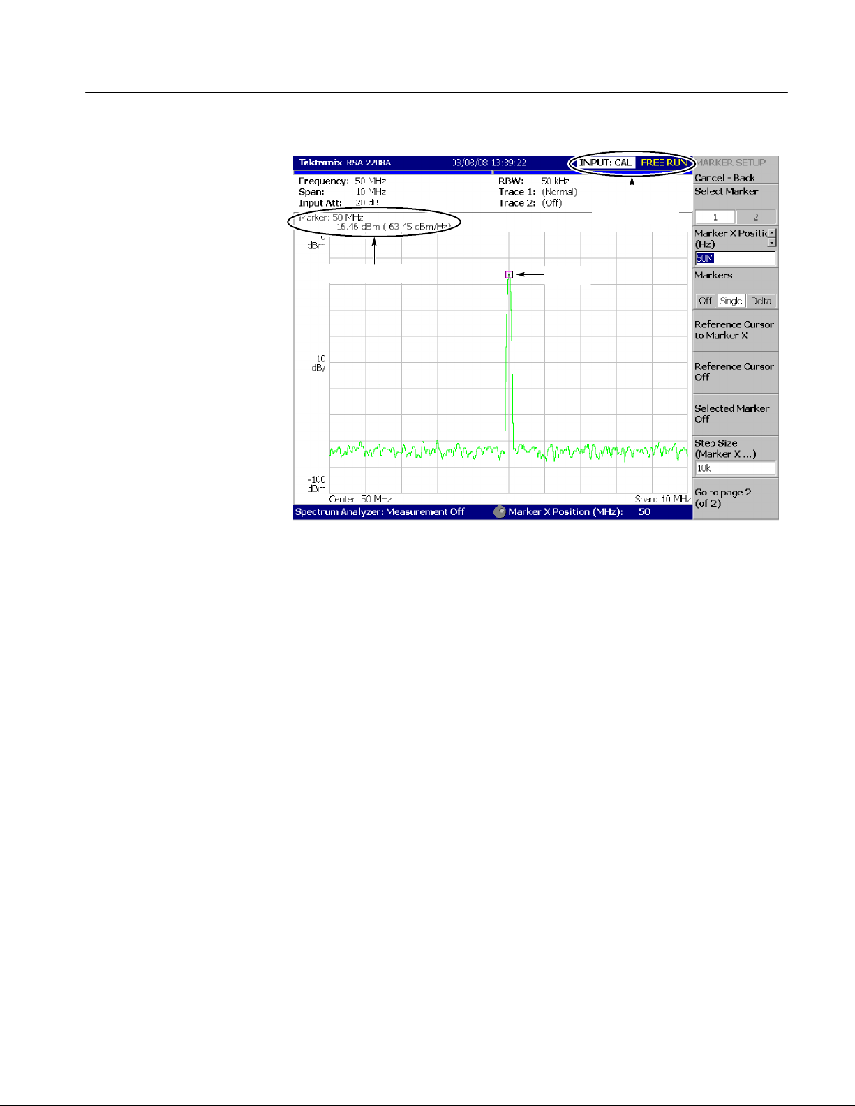
Status indicator
Brief Procedures
Marker readout
Marker
Figure 4- 1: Spectrum of the calibration signal (50 MHz, - 20 dBm)
5. Check the center frequency and peak amplitude using the marker:
a. Press the PEAK key on the front panel to place the m arker on the peak
(see Figure 4--1).
b. Check the marker readouts on screen. The frequency should be 50 MHz
and the amplitude should be approximately --20 dBm.
c. Press MARKER SETUP > Markers > Off.
Check that the marker disappears.
6. Check the RBW (Resolution Bandwidth) while changing the span setting.
a. Press the SPAN key on the front panel.
b. Confirm that the span is 10 MHz and the RB W is 50 kHz in the setup
display on t he upper part of the screen (see Figure 4--2).
RSA2203A & RSA2208A Service Manual
4- 5

Brief Procedures
Setup display
Span
RBW
Span setting
Figure 4- 2: Setup display
c. Using the general purpose knob, change the span setting as listed in
Table 4--1 and check that the RBW is displayed correctly.
Table 4- 1: Span and RBW
Span RBW
10 MHz 50 kHz
5MHz 20 kHz
100 kHz 500 Hz
1kHz 20 Hz
d. Using the numeric keypad, set the span back to 10 MHz.
(Press 1 > 0 > MHz, in that order, on t he keypad.)
7. Check the reference level:
a. Press the AMPLITUDE key on the front panel.
b. Make sure that the reference level is set to 0 dBm with the Ref Level
side key. C heck that 0 dBm is displayed on the upper left side of the
graticule (see Figure 4--3).
c. Use the general purpose knob to set the reference level to --30 dBm.
d. Confirm that A/D OVERFLOW is indicated in the red box at the top
center of the screen. Make s ure that --30 dBm is displayed on the upper
left side of the graticule and that the spectrum waveform is distorted as
shown in Figure 4--3.
e. Using the numeric keypad, set the reference level back to 0 dBm.
(Press 0 > ENTER, in that order, on the keypad.)
4- 6
RSA2203A & RSA2208A Service Manual

Reference level
Brief Procedures
A/D overflow indicator Reference level setting
Figure 4- 3: Reference level setting and A/D overflow indicator
Spectrogram
8. Check the spectrogram display:
a. Press S/A > S/ A with Spectrogram. Check that the spectrogram is
displayed on the lower side of the screen (see Figure 4--4).
Figure 4- 4: Spectrogram display
b. Press the RUN/STOP key on the front panel to stop data acquisition.
Confirm that the trace display freezes and PAUSE is displayed in the
status indicator at the top right of the screen.
RSA2203A & RSA2208A Service Manual
4- 7

Brief Procedures
Diagnostics
You can run the internal diagnostic program to check hardware states.
Table 4--2 shows the test items and their descriptions.
Table 4- 2: Internal diagnostic program
Menu item Description Possible failure
Temp Sensor Checks that the temperature sensor works correctly. RF5 module
Data Memory Checks that the acquisition memory works correctly. A41 board
The process is
graphically displayed
on the upper views.
Equipment
Required
Prerequisites Power on the analyzer and allow a 20 minute warm-up before doing
None
this procedure.
1. Press CAL > Service... > Password.
2. Enter 270833 andthenpresstheENTER key using the numeric keypad.
3. Press the DIAG side key.
4. Select the diagnostic menu item to be executed.
You may press the All side key to run all the tests.
5. Check the result shown in the lower left view with “Pass” or “Fail”.
4- 8
Figure 4- 5: Diagnostic screen
RSA2203A & RSA2208A Service Manual

Performance Tests
This section contains a collection of procedures for checking that the RSA2203A
and RSA2208A Real-Time Spectrum Analyzers perform as warranted.
STOP. These procedures extend the confidence level provided by the basic
procedures described on page 4--3. Perform the basic procedures first and then
perform the following procedures if desired.
There are two types of performance tests: Auto Tests and Manual Tests.
H Auto Tests use internal routines to verify that the analyzer functions properly
H Manual Tests supplement the Auto Tests to verify the analyzer performance
and was adjusted properly.
formally and report the test records.
RSA2203A & RSA2208A Service Manual
4- 9

Performance Tests
Prerequisites
The tests in this section comprise an extensive, valid confirmation of performance and functionality when the following requirements are met:
H The cabinet must be installed on the analyzer.
H The instrument must have passed the procedures under Brief Procedures
found on page 4--3.
H A signal-path compensation must have been done within the recommended
calibration interval and at a temperature within ±3 _C of the present
operating temperature. (If at the time you did the prerequisite Brief Proce-
dures, the temperature was within the limits just stated, consider this
prerequisite met.)
H The analyzer must have been last adjusted at an ambient temperature
between +20 _C and +30 _C, must have been operating for a warm-up
period of at least 20 minutes, and must be operating at an ambient temperature of between +10 _C and +40 _C. (The warm-up requirement is usually
met in the course of meeting the Brief Procedures prerequisites.)
H The SG flatness/spurious floppy disk(s) (Item 17 in Table 4--3) must be
prepared. For the procedure to create or update the flatness and spurious
correction files, refer to Making Flatness Correction Files on page 5--5 and
Making Spurious Correction Files on page 5--12.
Equipment Required
These procedures use external, traceable signal sources to directly check
warranted characteristics. Table 4--3 shows the required equipment.
Table 4- 3: Test equipment
Item number and
description
1. Signal generator
2. Signal generator Frequency range: 10 MHz to 8 GHz;
3. Signal generator Frequency range: 1 MHz to 8 GHz;
1
For RSA2203A, you can use the signal generator with the frequency range of 10 kHz to 3 GHz, for example Agilent 8648C.
1
Minimum requirements Example Purpose
Frequency range : 10 kHz to 3.5 GHz;
V ariable amplitude from --70 dBm to
+13 dBm into 50 Ω;
Accuracy: <±1 dB; Function: FM
Output level: --30 dBm to +10 dBm;
Accuracy: <±1dB
Output level: --30 dBm to +10 dBm;
Accuracy: <±1dB
Agilent 8648D Checking flatness in base-
band and RF1 band
Agilent 83712B with
option 1E1
Agilent E8257D with
option 1E1
(option UNX recommended)
Checking flatness in RF2 and
RF3 bands (RSA2208A only)
Checking flatness in all bands
4- 10
RSA2203A & RSA2208A Service Manual

Table 4- 3: Test equipment (Cont.)
Item number and
description
Performance Tests
PurposeExampleMinimum requirements
4. Signal generator Frequency: 2 GHz; Output:
≥--10 dBm; Digital modulation: QPSK;
Symbol rate: 4.096 M/s
5. Frequency counter Frequency range: 10 MHz;
Aging rate: <5×10
Accuracy: <0.01 ppm at 10 MHz
6. RF power meter 1MHzto8GHz Agilent E4418B Adjusting the signal generator
7. RF power sensor 10 MHz to 8 GHz; RF Flatness: <3%;
Uncertainty of calibration factor data:
<2% (RSS)
8. Power combiner Range: 500 MHz to 2 GHz; Isolation:
>18 dB; Insertion loss: <1.0 dB
9. BNC cable 50 Ω, 36 in, male-to-male BNC
connectors
10. N-N cable 50 Ω, 36 in, male-to-male N
connectors
11. N-SMA cable
(Three required)
12. GPIB cable
(Two required for
RSA2208A)
13. Terminator Impedance: 50 Ω; connectors: female
14. RF attenuator Ratio: 10 dB; impedance 50 Ω;
15. Mouse USB Standard accessary File operation
16. Keyboard USB Standard accessary File operation
17. SG flatness/spurious
floppy disk (for each
signal generator used)
50 Ω, 36 in, male N-to-male SMA
connectors
2m, double-shielded Tektronix part number
BNC input, male BNC output
Bandwidth: >8 GHz
Created or updated with the
procedures described on pages 5--5
and 5--12
-- 1 0
/day;
Rohde & Schwarz SMIQ03B Checking intermodulation
distortion
Agilent 53132A with
option 010
Agilent E4412A Adjusting the signal generator
Mini-Circuits ZAPD-21 Checking intermodulation
Tektronix part number
012-1341-XX
012-0991-XX
Tektronix part number
011-0049-01
Inmet 18N--10
Mini-Circuits BW-- S10W2
3.5 inch, 720 K or 1.44 MB,
DOS-compatible floppy disk
Checking the reference output frequency accuracy
output level
output level
distortion
Signal interconnection
Signal interconnection
Signal interconnection
Software-based tests
Signal termination for checking frequency accuracy
Checking flatness
Storing flatness and spurious
correction data for the signal
generators (Item 1, 2, and 3)
RSA2203A & RSA2208A Service Manual
4- 11

Performance Tests
Auto Tests
The auto tests use internal routines to verify specifications for the following
characteristics:
H Baseband flatness
H IF flatness
H RF flatness
H Spurious response
Use the following service PV menu and procedure to set parameters and perform
the tests.
Service PV Menu
Selects the PV (performance verification) test items and bands. Access this menu
by pressing CAL > Service... > Password (270833) > PV (see Figure 4--6).
RSA2208A only
4- 12
Figure 4- 6: Auto test initial screen
RSA2203A & RSA2208A Service Manual

Performance Tests
The PV menu has the following controls:
PV Select. Selects the test items as shown in Table 4--4.
Table 4- 4: Test item selection
PV Select
Test item All Spurious Other
Baseband flatness ✓ ✓
IF flatness ✓ ✓
RF flatness ✓ ✓
Spurious response ✓ ✓
NOTE. The baseband test is performed for Option 05 (DC --20 MHz baseband
frequency extension) only. For an instrument without Option 05, you can
include the baseband in your test although it is actually skipped.
All Band. Performs the tests in all bands: Baseband, RF1, RF2, and RF3.
RF2 and RF3 are for RSA2208A only.
Measurement bandwidth: 1 MHz to 3 GHz (RSA2203A) / 8 GHz (RSA2208A)
BB. Performs the tests i n the baseband.
Measurement bandwidth: 1 MHz to 20 MHz
RF1. P erforms the tests in the RF 1 band.
Measurement bandwidth:
10 MHz to 3 GHz (RSA2203A) / 3.5 GHz (RSA2208A)
BB+RF1. P erforms the tests i n the baseband and RF1 band.
Measurement bandwidth: 1 MHz to 3 GHz (RSA2203A) / 3.5 GHz (RSA2208A)
RF2+RF3. Performs the tests i n the RF2 and RF3 band.
Measurement bandwidth: 3.5 GHz to 8 GHz
RF1+RF2+RF3. Performs the tests in the RF1, RF2, and RF3 band.
Measurement bandwidth: 10 MHz to 8 GHz
Config... Sets the signal generator manufacturer and the GPIB address.
RSA2203A & RSA2208A Service Manual
4- 13

Performance Tests
H SG Type. Selects the manufacturer of the generator for the GPIB command
system: HP or Anritsu.
NOTE. The HP setting also supports Agilent and Rohde & Schwarz products.
H GPIB Address. Sets the GPIB address of the generator.
STOP. Select either of these two procedures, depending on the signal generator(s) you use:
H Procedure 1 below:
Uses one signal generator, Item 3, which covers all measurement bands:
Baseband, RF1, RF2, and RF3.
H Procedure 2 on page 4--17:
Uses two signal generators: Item 1, which covers the baseband and
RF1 band, and Item 2, which covers the RF2 and RF3 bands.
Procedure 1
RF2 and RF3 are for RSA2208A only.
Performs the auto tests using one signal generator (Item 3), which covers all
measurement bands: Baseband, RF1, RF2, and RF3 (RF2 and RF3 are for
RSA2208A only).
Equipment
Required
Prerequisites Refer to page 4--10
One signal generator (Item 3)
One 50 Ω N-N coaxial cable (Item 10)
One 10 dB attenuator (Item 14)
One GPIB cable (Item 12)
One SG flatness/spurious floppy disk (Item 17)
4- 14
RSA2203A & RSA2208A Service Manual
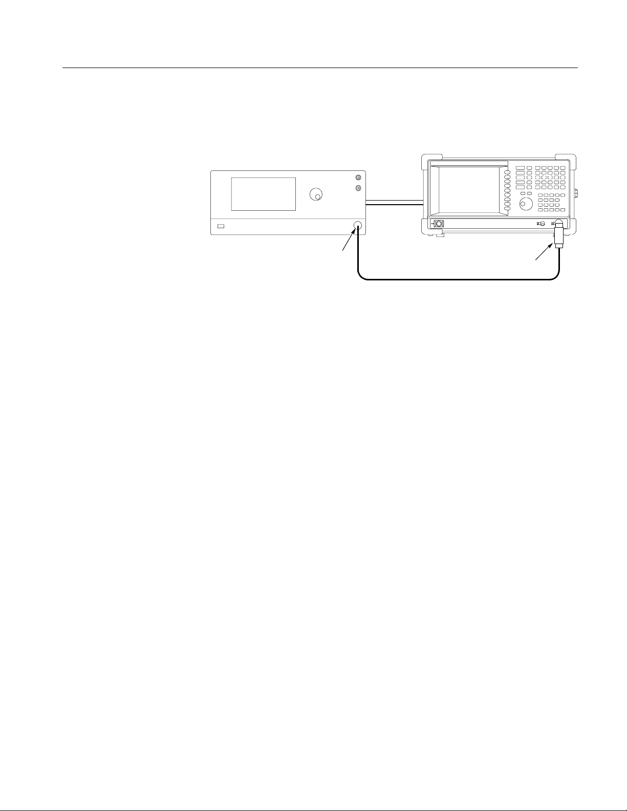
Performance Tests
1. Prepare for the test: See the following figure for the hookup.
RSA2203A/RSA2208A
Signal generator
GPIB cable
Output
50 Ω N-N coaxial cable
10 dB attenuator
a. Power off the analyzer and the generator.
b. Connect the analyzer and the generator with a GPIB cable.
c. Connect the analyzer INPUT through a 10 dB attenuator followed by a
50 Ω N-N coaxial cable to the generator output.
d. Power on the analyzer and the generator.
e. Set the GPIB address of the generator, ranging from 1 to 30.
f. Insert the SG flatness/spurious floppy disk (Item 17) for t he generator to
the floppy disk drive of the analyzer.
2. Perform the self calibration: Press CAL > Calibrate All.
3. Enter the PV menu:
a. Press Service... > Password in the CAL menu.
b. Enter 270833 andthenpressENTER using the numeric keypad.
c. Press the PV side key.
d. Set the GPIB address of the generator:
H Press the Config... side key.
H Press the SG Type side key to select the manufacturer of the
H Press the SG Address side key and set the generator address.
H Press the Cancel--Back side key.
RSA2203A & RSA2208A Service Manual
generator for the GPIB command system: HP or Anritsu.
4- 15
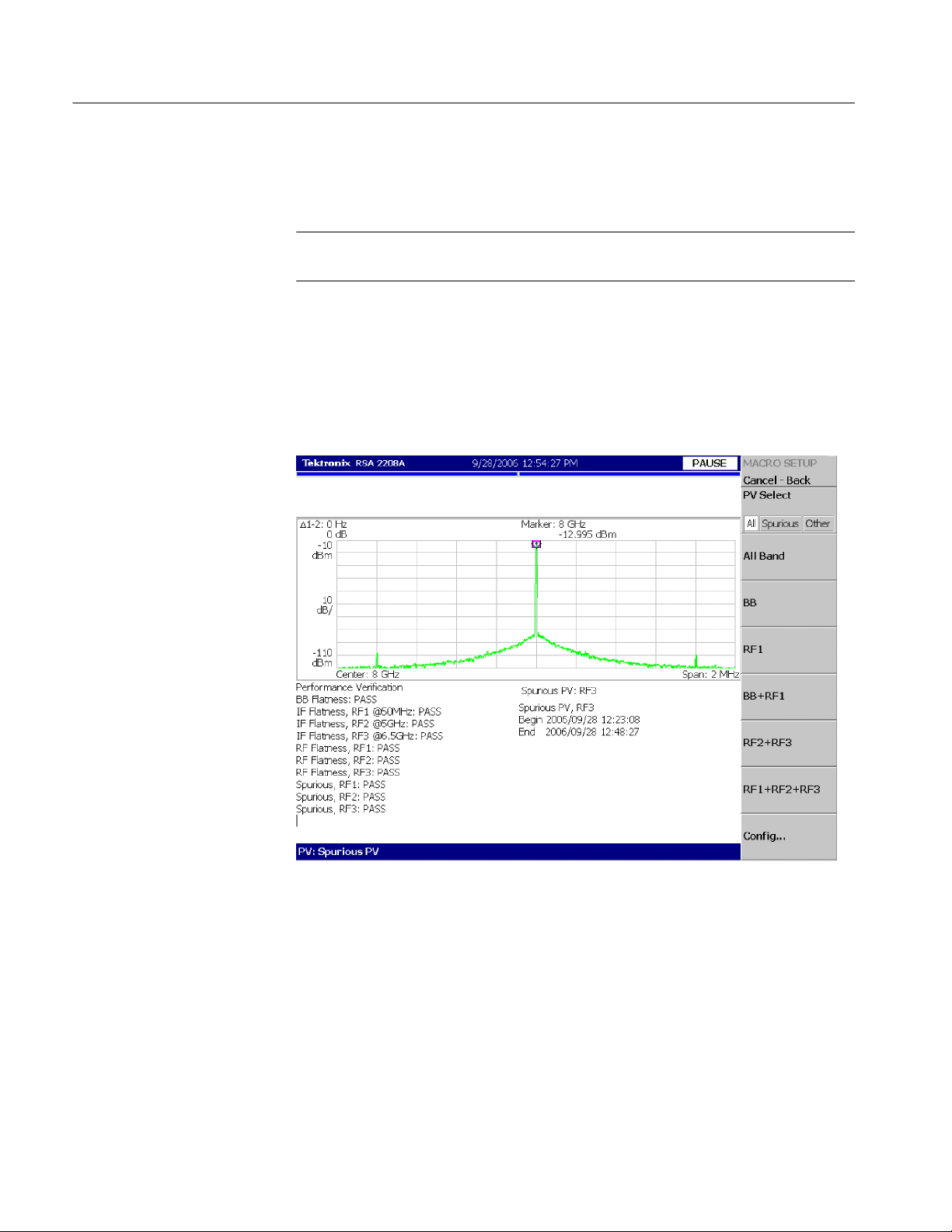
Performance Tests
4. Perform the tests in all bands:
Press the All Band side key to perform the tests.
NOTE. You can select the test items and bands as described in Service PV Menu
on page 4--12.
5. Check the test results:
Check the Pass/Fail results displayed on the lower left of the screen
(see Figure 4--7).
If the instrument fails any tests, go to When the Auto Tests Fail on
page 4--20.
4- 16
Figure 4- 7: Auto test result display example
6. Disconnect the test equipment:
a. Disconnect the cable from the analyzer input.
b. Turn off the analyzer and generators.
c. Disconnect the GPIB cables from all the ports.
RSA2203A & RSA2208A Service Manual

Performance Tests
A
/RSA
A
Procedure 2
Performs the auto tests using two signal generators: Item 1, which covers
the baseband and RF1 band, and Item 2, which covers the RF2 and RF3 bands
(RF2 and RF3 are for RSA2208A only).
Equipment
Required
Prerequisites Refer to page 4--10
Two signal generators (Items 1 and 2)
One 50 Ω N-N coaxial cable (Item 10)
One 10 dB attenuator (Item 14)
One GPIB cable (Item 12, two required)
One SG flatness/spurious floppy disk (Item 17, two required)
1. Prepare for the test:
Hook up the equipment as shown in the following figure.
GPIB cable
RSA2203
Signal generator (Item 1)Signal generator (Item 2)
GPIB cable
2208
Output
50 Ω N-N coaxial cable
10 dB attenuator
a. Power off the analyzer and the signal generators.
b. Connect the analyzer and the generators with GPIB cables.
c. Connect the analyzer INPUT through a 10 dB attenuator followed by a
50 Ω N-N coaxial cable to the generator (Item 1) output.
d. Power on the analyzer and the generators.
e. Set the GPIB address of the generators, ranging from 1 to 30.
Assign a unique address to each instrument.
f. Insert the SG flatness floppy/spurious disk (Item 17) for the generator
(Item 2) to the floppy disk drive of the analyzer.
2. Perform the self calibration: Press CAL > Calibrate All.
RSA2203A & RSA2208A Service Manual
4- 17

Performance Tests
3. Enter the PV menu:
a. Press Service... > Password in the CAL menu.
b. Enter 270833 andthenpressENTER using the numeric keypad.
c. Press the PV side key.
d. Set the GPIB address of the generator:
H Press the Config... side key.
H Press the SG Type side key to select the manufacturer of the
generator (Item 1) for the GPIB command system: HP or Anritsu.
H Press the SG Address side key and set the generator address.
H Press the Cancel--Back (top) side key.
4. Perform the tests in the baseband and RF1 band:
Press the BB+RF1 side key to perform the tests.
5. Check the test results:
Check the pass/fail results displayed on the lower left of the screen
(see Figure 4--7 on page 4--16).
If the instrument fails any tests, go to When the Auto Tests Fail on
page 4--20.
STOP. Steps 6 through 8 are the tests in the RF2 and RF3 bands for RSA2208A
only. For RSA2203A, skip to s tep 9.
6. Change the signal generator:
a. Disconnect the N--N cable from the signal generator (Item 1) output.
b. Connect the N--N cable to the signal generator (Item 2) output.
c. Set the GPIB address of the generator:
H Press the Config... side key.
H Press the SG Type side key to select the manufacturer of the
generator (Item 2) for the GPIB command system: HP or Anritsu.
H Press the GPIB Address side key and set the generator address.
4- 18
H Press the Cancel--Back (top) side key.
7. Perform the tests in the RF2 and RF3 bands:
Press the RF2+RF3 side key to perform the tests.
RSA2203A & RSA2208A Service Manual

8. Check the test results:
Check the pass/fail results displayed on the lower left of the screen
(see Figure 4--7 on page 4--16).
If the instrument fails any tests, go to When the Auto Tests Fail on
page 4--20.
9. Disconnect the test equipment:
a. Disconnect the N-N cable from the analyzer input.
b. Turn off the analyzer and generators.
c. Disconnect the GPIB cables from all the ports.
Performance Tests
RSA2203A & RSA2208A Service Manual
4- 19

Performance Tests
When the Auto Tests Fail
If any test results in Fail (see Figure 4--7 on page 4--16), perform calibration,
referring to Auto Calibration on page 5--19, and then perform the auto tests
again.
1. Perform the auto calibration for the failed test item as shown in Table 4--5.
Table 4- 5: Procedure for failed test item
Failed test item Procedure
BB Flatness Perform the baseband flatness calibration.
Use the All Band Calibration on page 5--21, but select BB in
the service Cal menu.
IF Flatness, RF1
IF Flatness, RF2
IF Flatness, RF3
RF Flatness, RF1
RF Flatness, RF2
RF Flatness, RF3
Spurious, RF1
Spurious, RF2
Spurious, RF3
Perform the IF flatness calibration.
Refer to All Band Calibration on page 5--21 for the procedure.
You can select RF1, RF2+RF3,orRF1+RF2+RF3 with
Cal Select in the service Cal menu for the band in which the
error occurred.
Perform the RF flatness calibration.
Refer to All Band Calibration on page 5--21 for the procedure.
You can select RF1, RF2+RF3,orRF1+RF2+RF3 with
Cal Select in the service Cal menu for the band in which the
error occurred.
Perform the spurious calibration.
Use the All Band Calibration on page 5--21, but select
Spurious wit h Cal Select in the service Cal menu.
You can select RF1, RF2+RF3,orRF1+RF2+RF3 in the
service Cal menu for the band in which the error occurred.
4- 20
2. Perform the auto tests again to check that the instrument passes.
If the instrument fails the spurious test again, go to the next section, Further
Spurious Test.
Further Spurious Test. Performs spurious test at the specified frequency.
1. Connect a USB mouse (Item 15) and keyboard (Item 16) to the USB ports
on the side panel of the analyzer.
2. Press MEASURE (front panel) > Spurious PV.
3. Set the GPIB address of the signal generator:
a. Press the SG side key to select the manufacturer of the generator for the
GPIB command system: HP or Anritsu.
b. Press the GPIB Address side key and set the generator address.
RSA2203A & RSA2208A Service Manual

Performance Tests
4. Check the error log:
Vi ew the error log in the following location using the mouse and keyboard:
NOTE. For accessing Windows XP on the analyzer, refer to the RSA2203A and
RSA2208A User Manual.
H Directory: C:\Program Files\Tektronix\wca200a\log
H File: spurious_RFxPV.log
(RFx = RF1, RF2, or RF3, depending on the test frequency)
Below is an example of the spurious_RF1PV.log file:
Spurious PV, RF1
Begin 2005/04/28 16:34:03
1000MHz: 67.5kHz, --73.065dB
2000MHz: 55.3kHz, --76.142dB
End 2005/04/28 17:02:05
Center frequency
Spurious offset frequency
from the center frequency
Difference in level between carrier
at the center frequency and
spurious at the offset frequency
5. Set test frequency:
a. Press the Band side key to select the band in which the error occurred.
For example, if an error occurred at 1000 MHz, select RF1.
b. Press the Start side key and set the frequency at which the error
occurred. For example, if an error occurred at 1000 MHz, enter 1000.
c. Press the Stop side key and set the same frequency as in Start (in this
example, 1000) to perform the measurement at the error frequency.
6. Perform the test: Press the Measurement side key to run the test.
Check that the test passes on the right bottom of the screen.
7. Repeat steps 5 and 6 for all the frequencies listed in the log file.
RSA2203A & RSA2208A Service Manual
4- 21

Performance Tests
Manual Tests
The manual tests include the following items:
H 10 MHz reference output
H Absolute amplitude accuracy
H Input attenuator setting uncertainty
H Spectrum purity
rd
H 3
H Frequency readout accuracy
H Spurious response
H Displayed average noise level
H Residual response
order intermodulation distortion
4- 22
RSA2203A & RSA2208A Service Manual

Performance Tests
10 MHz Reference Output
Test
Check that the output frequency from the REF OUT connector (on the rear
panel) is within the specified range for the analyzer.
Equipment
Required
Prerequisites Refer to page 4--10.
Frequency counter
CH1 input
50 Ω terminator
One frequency counter (Item 5)
One 50 Ω BNC coaxial cable (Item 9)
One 50 Ω terminator (Item 13)
The frequency counter must have been operating for a warm-up period
of at least 24 hours.
RSA2203A/RSA2208A (rear)
REF OUT
50 Ω BNC coaxial cable
Figure 4- 8: Initial test hookup
1. Prepare for the test:
a. Hook up the frequency counter: Connect REF OUT on the rear panel of
the analyzer through a 50 Ω precision coaxial cable and a 50 Ω precision
terminator to Channel 1 of the counter. See Figure 4--8.
b. Set the counter controls:
Function Frequency 1.................
Gate time 2 s................
2. Check the frequency: Check that the frequency counter reads
10 MHz ±1.2 Hz.
3. Disconnect the hookup: Disconnect the cable at REF OUT.
RSA2203A & RSA2208A Service Manual
4- 23

Performance Tests
Absolute Amplitude
Accuracy Test
Check that the absolute amplitude error is within the specified range for the
analyzer, using a power meter and a power sensor to set the signal generator
output accurately.
Equipment
Required
Prerequisites Refer to page 4--10.
One signal generator (Item 1)
One power meter (Item 6)
One power sensor (Item 7)
One 50 Ω N-N coaxial cables (Item 10)
1. Set up the power meter and sensor:
NOTE. Store the power sensor correction factors in the power meter, if you have
not yet done so. When you use the Agilent 437B power meter, refer to Storing Cal
Factors in the Power Meter on page 5--3.
a. Connect the power meter and the power sensor. See Figure 4-- 9 below.
Power meter
Power sensor
Sensor input
Figure 4- 9: Initial hookup for setting up the power meter and sensor
b. Warm up the power meter and sensor for more than 20 minutes.
c. Press ZERO on the power meter.
d. Connect the RF input of the power sensor to the power reference output
of the power meter. See Figure 4--10 on page 4--25.
e. Turn on POWER REF and execute the calibration.
f. Disconnect the RF input of the power sensor from the reference output
of the power meter.
4- 24
RSA2203A & RSA2208A Service Manual

Performance Tests
Power meter
Power reference output
Figure 4- 10: Hookup for calibrating the power sensor
STOP. Steps 2 through 5 are for Option 05 (Baseband frequency extension) only.
For the analyzer without Option 05, skip to step 6.
Baseband Test (Option 05 Only).
2. Set the signal generator output:
a. Hook up the instruments: Connect the signal generator (Item 1) output
through a 50 Ω N-N coaxial cable to the power sensor input. S ee
Figure 4--11.
Signal generator
Power meter
Output
Power sensor
Figure 4- 11: Hookup for setting the signal generator output
b. Set the signal generator controls:
Frequency 10 MHz................
Level --10 dBm....................
c. Set the power meter control:
RSA2203A & RSA2208A Service Manual
Frequency 10 MHz................
4- 25

Performance Tests
d. Adjust the output level of the signal generator so that the power meter
reads --10 dBm ±0.05 dBm.
e. Disconnect the cable from the power sensor input.
3. Prepare for the test:
a. Hook up the instruments: Connect the signal generator output through a
50 Ω N-N coaxial cable to the RSA2203A/RSA2208A INPUT.See
Figure 4--12.
RSA2203A/RSA2208A
Signal generator
Output
50 Ω N-N coaxial cable
Figure 4- 12: Hookup for checking the a bsolute amplitude accuracy
b. Initialize the analyzer:
H Press the SYSTEM key on the front panel.
H Press the Reset All to Factory Defaults side key.
c. Modify the default settings:
H Press the FREQUENCY/CHANNEL key on the front panel.
H With the Center Freq side key, set the frequency to 10 MHz using
the numeric keypad.
4. Check the amplitude:
a. Press the PEAK key on the front panel to place the m arker on the
signal peak.
b. Check that the marker readout is within --10 dBm ±0.3 dB.
4- 26
5. Disconnect the hookup: Disconnect the cable at the analyzer input.
RSA2203A & RSA2208A Service Manual

Performance Tests
RF ( RSA2203A) / RF1 (RSA2208A) Band Test.
6. Modify the signal generator output:
a. Hook up the test equipment: Connect the signal generator output through
a50Ω N-N coaxial cable to the power sensor input. See Figure 4--11 on
page 4--25.
b. Modify the signal generator controls:
Frequency 50 MHz................
Level --20 dBm....................
c. Modify the power meter control:
Frequency 50 MHz................
d. Adjust the output level of the signal generator so that the power meter
reads --20 dBm ±0.05 dBm.
e. Disconnect the cable from the power sensor input.
7. Modify the test hookup and preset the instrument controls:
a. Hook up the instruments: Connect the signal generator output through a
50 Ω N-N coaxial cable to the RSA2203A/RSA2208A INPUT.See
Figure 4--12 on page 4--26.
b. Initialize the analyzer:
Press SYSTEM > Reset All to Factory Defaults.
c. Calibrate the analyzer gain: Press CAL > Calibrate Gain.
d. Modify the analyzer controls:
H Press the FREQUENCY/CHANNEL key on the front panel.
H With the Center Freq side key, set the frequency to 50 MHz using
the numeric keypad.
H Press the AMPLITUDE key on the front panel.
H Press the RF Atten/Mixer side key to select RF Att.
H With the RF Att side key, set the attenuation to 0 dB.
8. Check the amplitude:
a. Press the PEAK key on the front panel to place the m arker on the
signal peak.
b. Check that the marker readout is within --20 dBm ±0.5 dB.
9. Disconnect the test equipment: Disconnect the cable at the analyzer input.
RSA2203A & RSA2208A Service Manual
4- 27
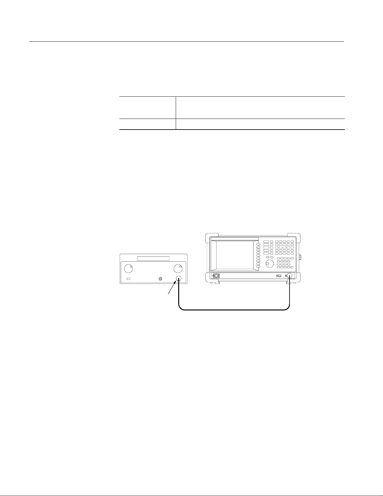
Performance Tests
Input Attenuator Setting
Uncertainty Test
Check the input attenuator setting error is within the specified range for the
analyzer.
Equipment
Required
Prerequisites Refer to page 4--10.
One signal generator (Item 1)
One 50 Ω N-N coaxial cables (Item 10)
1. Prepare for the test:
a. Set the generator controls:
Frequency 50 MHz................
Amplitude --25 dBm................
RF output On................
b. Hook up the generator: Connect the generator output through a 50 Ω
N-N coaxial cable to the analyzer INPUT. See Figure 4--13.
RSA2203A/RSA2208A
Signal generator
4- 28
Output
50 Ω N-N coaxial cable
Figure 4- 13: Initial test hookup
c. Initialize the analyzer:
H Press the SYSTEM key on the front panel.
H Press the Reset All to Factory Defaults side key.
RSA2203A & RSA2208A Service Manual

Performance Tests
d. Modify the default settings:
H Press the FREQUENCY/CHANNEL key on the front panel.
H With the Center Freq side key, set the frequency to 50 MHz using
the numeric keypad.
H Press the AMPLITUDE key on the front panel.
H With the Ref Level side key, set the reference level to --20 dBm
using the general purpose knob.
H Press the RF Atten/Mixer side key to select RF Att.
H With the RF Att side key, set the attenuation to 0 dB using the
numeric keypad or the general purpose knob.
2. Measure the reference amplitude at 0 dB attenuation:
a. Press the PEAK key on the front panel to place the m arker on the
signal peak.
b. Record the peak amplitude at the marker readout as the reference value.
(Let the value be P
)
0.
3. Check the amplitude for the attenuation from 10 to 30 dB:
a. Press AMPLITUDE > RF Att and set the attenuation (initially 10 dB).
b. Press the PEAK key on the front panel to place the marker on the
signal peak.
c. Record the peak amplitude at the marker readout. (Let the value be P
d. Check that the error (P
-- P0) is within ±0.5 dB.
X
e. Repeat substeps 3a through d forattenuationfrom10to30dBin10dB
steps.
4. Modify the generator controls:
Amplitude --5 dBm................
5. Modify the analyzer controls:
a. Press the AMPLITUDE key on the front panel.
b. With the Ref Level side key, set the reference level to 0 dBm using the
general purpose knob.
.)
X
c. Make sure that RF Att is set to 30 dB.
RSA2203A & RSA2208A Service Manual
4- 29

Performance Tests
6. Measure the reference amplitude at 30 dB attenuation:
a. Press the PEAK key on the front panel to place the m arker on the
signal peak.
b. Record the peak amplitude at the marker readout as the reference value.
(Let the value be P
)
1.
7. Check the amplitude for attenuation from 40 and 50 dB:
a. Press AMPLITUDE > RF Att and set the attenuation (initially 40 dB).
b. Press the PEAK key on the front panel to place the marker on the
signal peak.
c. Record the peak amplitude at the marker readout. (Let the value be P
d. Check that the error (P
-- P1) is within ±0.5 dB.
X
e. Repeat substeps 7a through d for attenuation of 40 and 50 dB.
8. Disconnect the test equipment: Disconnect the cable at the analyzer input.
.)
X
4- 30
RSA2203A & RSA2208A Service Manual

Performance Tests
Spectrum Purity Test
Check that the spectrum purity is within the specified range for the analyzer.
Equipment
Required
Prerequisites Refer to page 4--10.
Signal generator
One signal generator (Item 4)
One 50 Ω N-N coaxial cable (Item 10)
RSA2203A/RSA2208A
Output
50 Ω N --N coaxial cable
Figure 4- 14: Initial test hookup
1. Prepare for the test:
a. Initialize the analyzer:
H Press the SYSTEM key on the front panel.
H Press the Reset All to Factory Defaults side key.
b. Modify the default settings:
H Press the AMPLITUDE key on the front panel.
H Press the RF Atten/Mixer side key to select Mixer.
H With the Mixer Level side key, set the level to --15 dBm.
H Press the TRACE/AVG key.
H Press the side key Trace 1 Type. . . > Average.
H Press the Number Of Averages side key and set the value to 50
using the general purpose knob.
RSA2203A & RSA2208A Service Manual
4- 31

Performance Tests
c. Set the generator controls:
Frequency 1500 MHz................
Amplitude --5 dBm................
RF output On................
d. Hook up the s ignal generator: Connect the generator output through a
50 Ω N-N coaxial cable to the analyzer INPUT. See Figure 4--14.
2. Check phase noise for a span of 100 kHz:
a. Modify the analyzer controls:
H Press the SPAN key on the front panel.
H With the Span side key, set the span to 100 kHz using the general
purpose knob or the numeric keypad.
H Press the RBW/FFT key on the front panel.
H Press the RBW/FFT side key to select Man.
H With the RBW side key, set the RBW to 200 Hz.
b. Perform t he C/N (Carrier-to-Noise ratio) measurement:
H Press the MEASURE > C/N > MEAS SETUP key.
H Press the Offset Frequency side key and set the value to 10 kHz
using the general purpose knob.
H Press the Noise Bandwidth side key and set the value to 2 kHz
using the general purpose knob.
c. Check against limits: Read the phase noise (C/No) at the bottom of the
screen. Confirm that the value is 100 dB/Hz or more.
3. Check phase noise for a span of 1 MHz:
a. Modify the analyzer controls:
H Press the SPAN key on the front panel.
H With the Span side key, set the span to 1 MHz using the general
purpose knob or the numeric keypad.
H Press the RBW/FFT key on the front panel.
4- 32
H Press the RBW/FFT side key to select Man.
H With the RBW side key, set the RBW to 2 kHz.
RSA2203A & RSA2208A Service Manual

Performance Tests
b. Perform the C/N measurement:
H Select MEASURE > C/N > MEAS SETUP.
H Press the Offset Frequency side key and set the value to 100 kHz
using the general purpose knob.
H Press the Noise Bandwidth side key and set the value to 20 kHz
using the general purpose knob.
c. Check against limits: Read the phase noise (C/No) at the bottom of the
screen. Confirm that the value is 105 dB/Hz or more.
4. Check phase noise for a span of 5 MHz:
a. Modify the analyzer controls:
H Press the SPAN key on the front panel.
H With the Span side key, set the span to 5 MHz using the general
purpose knob or the numeric keypad.
H Press the RBW/FFT key on the front panel.
H Press the RBW/FFT side key to select Man.
H Press the Extended Resolution side key to select On.
H With the RBW side key, set the RBW to 5 kHz.
b. Perform the C/N measurement:
H Select MEASURE > C/N > MEAS SETUP.
H Press the Offset Frequency side key and set the value to 1 M Hz
using the general purpose knob.
H Press the Noise Bandwidth side key and set the value to 200 kHz
using the general purpose knob.
c. Check against limits: Read the phase noise (C/No) at the bottom of the
screen. Confirm that the value is 125 dB/Hz or more.
5. Disconnect the test equipment: Disconnect the cable at the analyzer input.
RSA2203A & RSA2208A Service Manual
4- 33
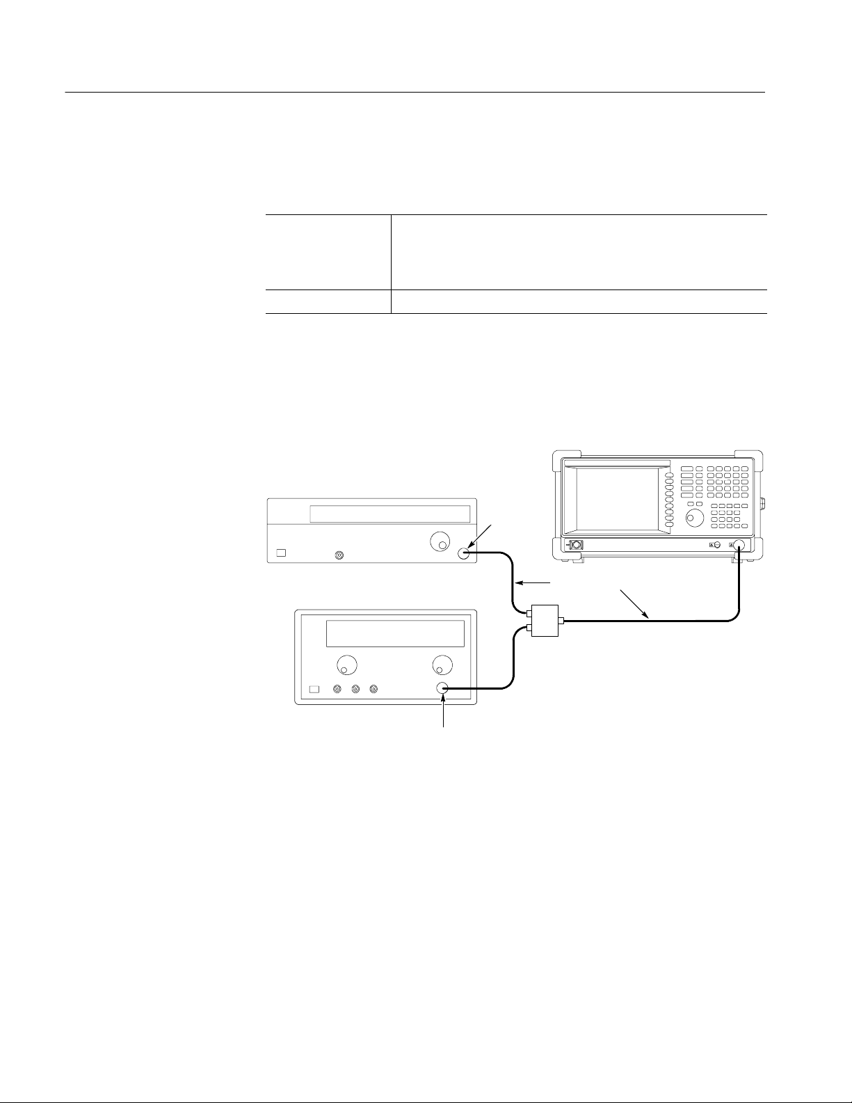
Performance Tests
3rdOrder Intermodulation
Distortion Test
Check that the 3
for the analyzer .
rd
order intermodulation distortion is within the specified range
Equipment
Required
Prerequisites Refer to page 4--10.
Two signal generators (Items 2 and 4)
One power combiner (Item 8)
Three 50 Ω N-SMA coaxial cables (Item 11)
1. Prepare for the test:
a. Connect each generator output through a 50 Ω N-SMA coaxial cable to
each power combiner input. See the figure below.
RSA2203A/RSA2208A
Signal generator
Output
N-SMA cable
Signal generator
Power
combiner
N-SMA cable
Output
b. Connect the power combiner output through a 50 Ω N-SMA coaxial
cable to the analyzer INPUT.
c. Set the signal generator (Item 2) controls:
Frequency 1999.85 MHz................
Level 0 dBm....................
ALC BW 100 Hz................
d. Set the signal generator (Item 4) controls:
Frequency 2000.15 MHz................
Level 0 dBm....................
ALC BW 100 Hz................
4- 34
RSA2203A & RSA2208A Service Manual

Performance Tests
e. Initialize the analyzer:
H Press the SYSTEM key on the front panel.
H Press the Reset All to Factory Defaults side key.
f. Modify the default controls:
H Press the FREQUENCY/CHANNEL key on the front panel.
H With the Center Freq side key, set the frequency to 2 GHz using the
numeric keypad.
H Press the SPAN key on the front panel.
H With the Span side key, set the span to 1 MHz using the general
purpose knob.
H Press the AMPLITUDE key on the front panel.
H With the Ref Level side, and set the level to 5 dBm using the
general purpose knob.
H Press the RF Atten/Mixer side key to select Rf Att.
H With the RF Att side key, set the attenuation to 15 dB using the
general purpose knob.
H Press the RBW/FFT key on the front panel.
H Press the RBW/FFT side key to select Man.
H Press the Extended Resolution side key to select On.
H Press the RBW side key, set the R BW to 2 kHz.
g. Modify the generator output level:
H Press MARKERS: A or " to place the marker on the signal of
1999.85 MHz.
H Adjust the generator (Item 2) output level so that the signal level is
--10 dBm.
H Press MARKERS: A or " to place the marker on the signal of
2000.15 MHz.
H Adjust the generator (Item 4) output level so that the signal level is
--10 dBm.
RSA2203A & RSA2208A Service Manual
4- 35

Performance Tests
2. Check the amplitude:
a. Modify the analyzer controls:
H Press TRACE/AVG > Trace 1 Typ e... > Average.
H Press the Number Of Averages side key and set the value to 50
using the general purpose knob.
H Press the MARKER SETUP key.
H Press the Markers side key to select Delta.
b. Measure the amplitude for the signals of 1999.55 MHz and
2000.45 MHz:
H Press the Select Marker side key to select 1.
H Place the first marker at the signal of 1999.55 MHz using the
MARKERS: A or " key.
H Press the Select Marker side key to select 2.
H Place the second marker at the signal of 2000.45 MHz using the
MARKERS: A or " key.
c. Check against limits: Read the first and the second marker readouts.
Confirm that t he larger value meets the requirement of --73 dBc.
3. Disconnect the test equipment: Disconnect the cable at the analyzer input.
4- 36
RSA2203A & RSA2208A Service Manual
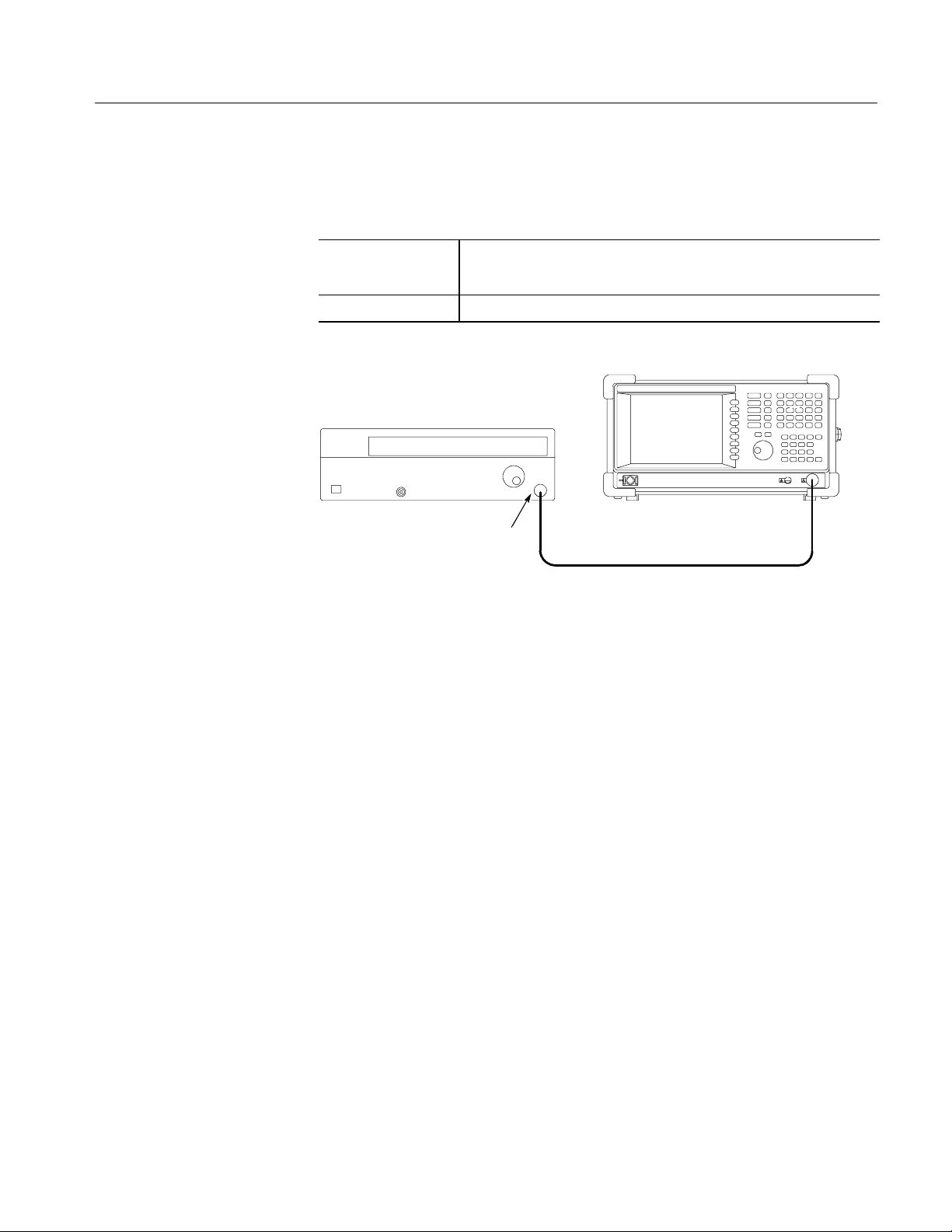
Performance Tests
Frequency Readout Test
Check that the frequency readout accuracy is within the specified range for the
analyzer at 10 MHz (Option 05 only), 2 GHz, 5 GHz, and 7 GHz.
Equipment
Required
Prerequisites Refer to page 4--10.
Signal generator
One signal generator (Item 2)
One 50 Ω N-N coaxial cable (Item 10)
RSA2203A/RSA2208A
Output
50 Ω N-N coaxial cable
Figure 4- 15: Initial test hookup
1. Prepare for the test:
a. Initialize the analyzer:
H Press the SYSTEM key on the front panel.
H Press the Reset All to Factory Defaults side key.
b. Set the generator controls:
Frequency 10 MHz................
Level --10 dBm....................
c. Hook up the signal generator: Connect the generator output through a
50 Ω N-N coaxial cable to the analyzer INPUT. See Figure 4--15.
RSA2203A & RSA2208A Service Manual
4- 37

Performance Tests
2. Check frequency accuracy in the baseband (Option 05 only):
a. Modify the analyzer default settings:
H Press the FREQUENCY/CHANNEL key on the front panel.
H With the Center Freq side key, set the frequency to 10 MHz using
the numeric keypad.
H Press the SPAN key on the front panel.
H With the Span side key, set the span to 1 MHz using the general
purpose knob.
b. Measure peak frequency:
H Press the PEAK key to place the marker on the signal peak.
H Read the marker readout. Confirm that the value is
10 MHz ±1kHz.
H Press MEASURE > Carrier Frequency.
H Read the measurement result at the bottom of the screen.
Confirm that the value is 10 MHz ±50 Hz (without Option 10) /
±1.2 Hz (with Option 10).
3. Check frequency accuracy in the RF (RSA2203A) /RF1 (RSA2208A) band:
a. Modify the generator control:
Frequency 2 GHz................
b. Modify the analyzer controls:
H Press the FREQUENCY/CHANNEL key on the front panel.
H With the Center Freq side key, set the frequency to 2 GHz using the
numeric keypad.
H Press the SPAN key on the front panel.
H With the Span side key, set the span to 1 MHz using the general
purpose knob.
4- 38
RSA2203A & RSA2208A Service Manual

Performance Tests
c. Measure peak frequency:
H Press the PEAK key to place the marker on the signal peak.
H Read the marker readout. Confirm that the value is
2 GHz ±5 kHz (without Option 10) / ±1.2 kHz (with Option 10).
H Press MEASURE > Carrier Frequency.
H Read the measurement result at the bottom of the screen.
Confirm that the value i s 2 GHz ±4 kHz (without Option 10) /
±210 Hz (with Option 10).
STOP. Steps 4 and 5 are the tests in the RF2 and RF3 bands for RSA2208A only.
For RSA2203A, skip to step 6.
4. Check frequency accuracy in the RF2 band for RSA2208A:
a. Modify the generator control:
Frequency 5 GHz................
b. Modify the analyzer controls:
H Press the FREQUENCY/CHANNEL key on the front panel.
H With the Center Freq side key, set the frequency to 5 GHz using the
numeric keypad.
c. Measure peak frequency:
H Press the PEAK key to place the marker on the signal peak.
H Read the marker readout. Confirm that the value is
5 GHz ±11 kHz (without Option 10) / ±1.5 kHz (with Option 10).
H Press MEASURE > Carrier Frequency.
H Read the measurement result at the bottom of the screen.
Confirm that the value i s 5 GHz ±10 kHz (without Option 10) /
±510 Hz (with Option 10).
RSA2203A & RSA2208A Service Manual
4- 39

Performance Tests
5. Check frequency accuracy in the RF3 band for RSA2208A:
a. Modify the generator control:
Frequency 7 GHz................
b. Modify the analyzer controls:
H Press the FREQUENCY/CHANNEL key on the front panel.
H With the Center Freq side key, set the frequency to 7 GHz using the
numeric keypad.
c. Measure peak frequency:
H Press the PEAK key to place the marker on the signal peak.
H Read the marker readout. Confirm that the value is
7 GHz ±15 kHz (without Option 10) / ±1.7 kHz (with Option 10).
H Press MEASURE > Carrier Frequency.
H Read the measurement result at the bottom of the screen.
Confirm that the value i s 7 GHz ±14 kHz (without Option 10) /
±710 Hz (with Option 10).
6. Disconnect the test equipment: Disconnect the cable at the analyzer input.
4- 40
RSA2203A & RSA2208A Service Manual

Performance Tests
Spurious Response Test
Check that the spurious response is within the specified range for the analyzer.
Equipment
Required
Prerequisites Refer to page 4--10.
Signal generator
One signal generator (Item 2)
One 50 Ω N-N coaxial cable (Item 10)
RSA2203A/RSA2208A
Output
50 Ω N-N coaxial cable
Figure 4- 16: Initial test hookup
1. Prepare for the test:
a. Initialize the analyzer:
H Press the SYSTEM key on the front panel.
H Press the Reset All to Factory Defaults side key.
b. Modify the default controls:
H Press the RBW/FFT key on the front panel.
H Press the RBW/FFT side key to select Man.
H With the RBW side key, set the value to 50 kHz using the general
purpose knob.
H Press the TRACE/AVG key on the front panel.
H Press the Tra ce 1 Type. . . side key and select Average.
H Press the Number Of Averages side key and set the value to 50.
H Press the MARKER SETUP key.
H Press the Markers side key to select Delta.
RSA2203A & RSA2208A Service Manual
4- 41

Performance Tests
c. Set the generator controls:
Level --5 dBm....................
d. Hook up the s ignal generator: Connect the generator output through a
50 Ω N-N coaxial cable to the analyzer INPUT. See Figure 4--16.
2. Check spurious response:
a. Modify the generator controls: Set the generator output frequency to the
value as shown in Table 4--6 (initially 10 MHz (with Option 05) / 2 GHz
(without Option 05)).
b. Modify the analyzer controls:
H Press the FREQUENCY/CHANNEL key on the front panel.
H With the Center Freq side key, set the frequency to the same value
as the generator output using the numeric keypad.
c. Measure the amplitude:
H Press the MARKER SETUP key.
H Press the Select Marker side key to select 1.
H Press the PEAK key and then the MARKERS: B (marker down)
key once to place the first marker at the peak on the noise floor.
H Press the Select Marker side key to select 2.
H Press the PEAK keytoplaceMarker2onthesignalpeak.
H Read the delta marker readout (∆1--2) on the screen. Check that the
components other than the carrier meet the requirement as shown in
Table 4--6 (initially --73 dBc).
d. Repeat substeps a through c until all frequency settings listed in
Table 4--6 are checked.
Table 4- 6: Spurious measurement
Band Frequency Spurious response
Baseband (Option 05 only) 10 MHz --73 dBc
RF (RSA2203A) / RF1 (RSA2208A) 2GHz --73 dBc
4- 42
RF2 (RSA2208A only) 5GHz --70 dBc
RF3 (RSA2208A only) 7GHz --70 dBc
3. Disconnect the test equipment: Disconnect the cable at the analyzer input.
RSA2203A & RSA2208A Service Manual

Performance Tests
Displayed Average Noise
Level Test
Check that the displayed average noise level is within the specified range for the
analyzer.
Equipment
Required
Prerequisites Refer to page 4--10.
RSA2203A/RSA2208A
None
Figure 4- 17: Initial test hookup
1. Prepare for the test:
a. Initialize the analyzer:
Press SYSTEM > Reset All to Factory Defaults.
b. Modify the analyzer controls:
H Press the SPAN key on the front panel.
H With the Span side key, set the span to 1 MHz using the general
purpose knob.
H Press the RBW/FFT key on the front panel.
H Press the RBW/FFT side key to select Man.
H With the RBW side key, set the value to 10 kHz using the general
purpose knob.
H Press the TRACE/AVG key on the front panel.
H Press the Tra ce 1 Type. . . side key and select Average.
H Press the Number Of Averages side key and set the value to 50.
H Press MEASURE > Channel Power.
H Press MEAS SETUP > Channel Bandwidth and set the value to
1 MHz using the general purpose knob.
RSA2203A & RSA2208A Service Manual
4- 43

Performance Tests
2. Check noise at 10 MHz in the baseband (Option 05 only):
a. Modify the analyzer control:
H Press the FREQUENCY/CHANNEL key on the front panel.
H With the Center Freq side key, set the frequency to 10 MHz using
the general purpose knob.
H Press the AMPLITUDE key on the front panel.
H With the Ref Level side key, set the level to --30 dBm using the
general purpose knob.
b. Check against limits: Read the measurement result of Density at the
bottom of the screen. Check that the value is --150 dBm/Hz or less.
3. Check noise at 2 GHz in the RF (RSA2203A) / RF1 (RSA2208A) band:
a. Modify the analyzer control:
H Press the FREQUENCY/CHANNEL key on the front panel.
H With the Center Freq side key, set the frequency to 2 GHz using the
general purpose knob.
H Press the AMPLITUDE key on the front panel.
H With the Ref Level side key, set the level to --40 dBm using the
general purpose knob.
H Press the RF Atten/Mixer side key to select RF Att.
H With the RF Att side key, set the attenuation to 0 dB using the
general purpose knob.
b. Check against limits: Read the measurement result of Density at the
bottom of the screen. Check that the value is --148 dBm/Hz or less.
4. Check noise at 3 GHz in the RF (RSA2203A) / RF1 (RSA2208A) band:
a. Modify the analyzer control:
H Press the FREQUENCY/CHANNEL key on the front panel.
H With the Center Freq side key, set the frequency to 3 GHz using the
general purpose knob.
4- 44
b. Check against limits: Read the measurement result of Density at the
bottom of the screen. Check that the value is --147 dBm/Hz or less.
RSA2203A & RSA2208A Service Manual

Performance Tests
5. Check noise at 7 GHz in the RF3 band for RSA2208A only:
a. Modify the analyzer control:
H Press the FREQUENCY/CHANNEL key on the front panel.
H With the Center Freq side key, set the frequency to 7 GHz using the
general purpose knob.
b. Check against limits: Read the measurement result of Density at the
bottom of the screen. Check that the value is --142 dBm/Hz or less.
RSA2203A & RSA2208A Service Manual
4- 45

Performance Tests
Residual Response Test
Check that the residual noise level is within the specified range for the analyzer.
Equipment
Required
Prerequisites Refer to page 4--10.
RSA2203A/RSA2208A
None
Figure 4- 18: Initial test hookup
1. Prepare for the test:
a. Initialize the analyzer:
H Press the SYSTEM key on the front panel.
H Press the Reset All to Factory Defaults side key.
b. Modify the default settings:
H Press the AMPLITUDE key on the front panel.
H With the Ref Level side key, set the level to --30 dBm using the
general purpose knob.
H Press the RBW/FFT key on the front panel.
H Press the RBW/FFT side key to select Man.
H With the RBW side key, set the RBW to 100 kHz using the general
purpose knob.
H Press the TRACE/AVG key on the front panel.
H Press the Tra ce 1 Type. . . side key and select Average.
H Press the Number Of Averages side key and set the value to 50
using the general purpose knob.
4- 46
RSA2203A & RSA2208A Service Manual

2. Check residual response in the baseband (Option 05 only):
a. Modify the analyzer controls:
H Press the FREQUENCY/CHANNEL key on the front panel.
H With the Center Freq side key, set the frequency to 10 MHz using
the general purpose knob.
H Press the SPAN key on the front panel.
H With the Span side key, set the span to 20 MHz using the general
purpose knob.
b. Measure residual response:
H Press the LINES key on the front panel.
H Press the Show Line side key to select Vertical.
H Press the Number Of Line key to select 1.
Performance Tests
H With the Line1 side key, set the value to 1 MHz using the numeric
keypad.
H Press the Show Line side key to select Horizontal.
H Press the Number Of Line key to select 1.
H With the Line1 side key, set the value to --93 dBm using the numeric
keypad.
c. Check against limits: Confirm that the residual signal level is --93 dBm
or less at 1 MHz or more.
3. Check residual response in the RF band (up to 3 GHz):
a. Modify the analyzer controls:
H Press the FREQUENCY/CHANNEL key on the front panel.
H With the Center Freq side key, set the frequency to 1.5 GHz using
the numeric keypad.
H Press the SPAN key on the front panel.
H With the Span side key, set the span to 3 GHz using the numeric
keypad.
RSA2203A & RSA2208A Service Manual
4- 47

Performance Tests
b. Measure residual response:
H Press the LINES key.
H Press the Show Line side key to select Vertical.
H Press the Number Of Line key to select 1.
H Press the Line1 side key and set t he value to 100 MHz.
H Press the Show Line side key to select Horizontal.
H Press the Number Of Line key to select 1.
H Press the Line1 side key and set t he value to --90 dBm using the
numeric keypad.
c. Check against limits: Confirm that the residual signal level is --90 dBm
or less at 100 MHz or more.
4. Check residual response in the RF1 band for RSA2208A only:
a. Modify the analyzer controls:
H Press the SPAN key on the front panel.
H With the Stop Freq side key, set the frequency to 3.5 GHz using the
numeric keypad.
b. Measure residual response: Press the PEAK key to place the marker at
the peak on the noise floor.
c. Check against limits: Read the marker readout. Confirm t hat the residual
signal level is --90 dBm or less within the whole bandwidth.
5. Check residual response in the RF2 band for RSA2208A only:
a. Modify the analyzer controls:
H Press the FREQUENCY/CHANNEL key on the front panel.
H With the Center Freq side key, set the frequency to 5 GHz using the
numeric keypad.
b. Measure residual response: Press the PEAK key to place the marker at
the peak on the noise floor.
c. Check against limits: Read the marker readout. Confirm t hat the residual
signal level is --85 dBm or less within the whole bandwidth.
4- 48
RSA2203A & RSA2208A Service Manual
 Loading...