

Page 1

xx
RMB2020
ZZZ
Rackmount Kit
Installation Instructions
www.tek.com
P075109801*
*
075-1098-01
Page 2

Copyright © Tektronix. All rights reserved. Licensed software products are owned by Tektronix or its subsidiaries
or suppliers, and are protected by national copyright laws and international treaty provisions.
Tektronix products are covered by U.S. and foreign patents, issued and pending. Information in this publication
supersedes that in all previously published material. Specifications and price change privileges reserved.
TEKTRONIX and TEK are registered trademarks of Tektronix, Inc.
Contacting Tektronix
Tektronix, Inc.
14150 SW Karl Braun Drive
P.O. Box 5 0 0
Beaverto
USA
For product information, sales, service, and technical support:
n, OR 97077
In North America, call 1-800-833-9200.
Worldwide, visit www.tek.com to find contacts in your area.
Page 3

Service safety summary
Only qualified personnel should perform service procedures. Read this Service
Safety Summary and the General Safety Summary in the product service manual
or the instru
Do Not Service Alone. Do not perform internal service or adjustments of this
product unless another person capable of rendering first aid and resuscitation is
present.
To prevent the instrument and rack from falling on the operator, two or more
installers should install the instrument into the rack cabinet. After completing the
installation procedure, the installers should verify that the instrumentandrack
cabinet
Disconnect Power. To avoid electric shock, switch off the instrument power, then
disconnect the power cord from the mains power.
UseCareWhenServicingWithPowerOn. Dangerousvoltagesorcurrentsmay
in this product. Disconnect power and disconnect test leads before removing
exist
protective panels, soldering, or replacing components.
To av
ction manual.
will not tip forward while the instrument is in the extended position.
oid electric shock, do not touch exposed connections.
RMB2020 Rackmount Kit Installation Instructions 1
Page 4

Kit description
Kit description
Products
These instructions describe the installation of the rackmount kit to your standard
bench-top instrument. The rackmount kit is a collection of parts that, once
installed, c
onfigure the instrument for mounting in a fixed position into a standard
19-inch equipment rack.
TBS2xx2 Series AllSerialNumbers
Kit parts list
Table 1: RMB2020 rackmount kit
Item Quanti
–
1 2 367-0
2 1 each 407-6065-00
3 1 each 407-6032-00
41each407
5
6 1 each 407-6073-00
–
ty
1 each 075-1098-00
1 each 407-6031-00
4
1
mber
Part nu
450-00
-6074-00
11-1275-00
2
TBS2xx2B S
The foll
Descri
TECH MANUAL: INSTRUCTIONS, THIS DOCUMENT
HANDLE, BOW; CARRYING
BRAC
BRACKET, TOP
BRACKET, LEFT SIDE
BR
BRACKET, RIGHT SIDE
SCREW, MACHINE, 6-32 X .312 PANHEAD T15, WITH THREAD LOCKING PATCH
eries AllSerialNumbers
owing table and figure show the parts list of the rackmount kit.
ption
KET, TOP HOLDER
ACKET, BOTTOM
2 RMB2020 Rackmount Kit Installation Instructions
Page 5
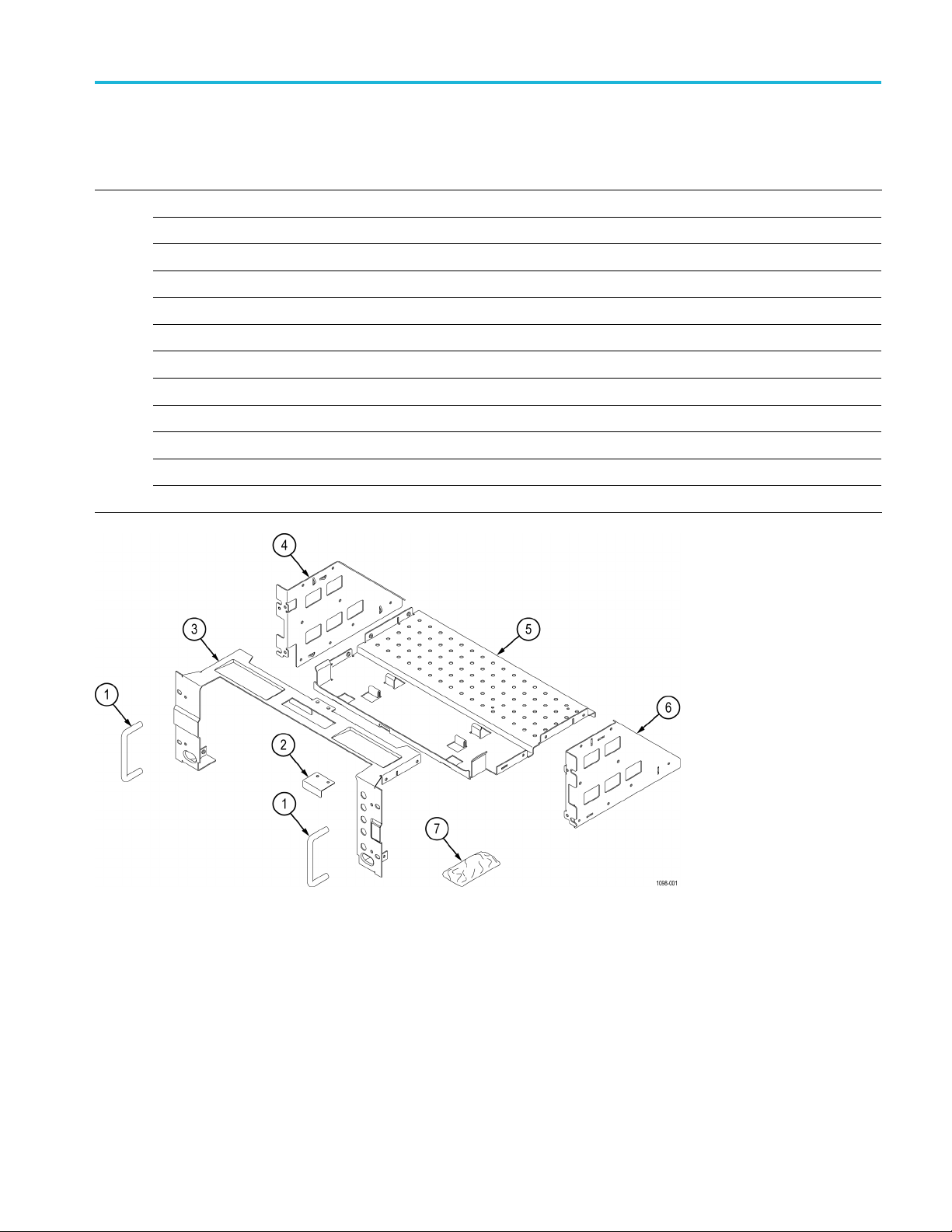
Table 1: RMB2020 rackmount kit, (cont.)
Item Quantity Part number Description
Kit description
7
1 each 016-2006-00 KIT, HARDWARE
4 210-0833-00
4 210-1061-00
4 210-1546-00
4 210-1547-00
4 210-1548-00
14 211-0507-00
4 211-0538-00
4 211-1218-00
4 211-1219-00
4 212-0591-00
4 213-0199-00
WASHER, RECESSED; 0.42 ID X 0.112 THK, STL NI PLATED, 0.588 OD
WASHER, FLAT; 0.203 ID X 0.625 OD X 0.062, ZINC P LATED STEEL
SCREW, MACHINE, PANHEAD 8-32 X .500, PHILLIPS
WASHER, LOCK NO. 8, SPLIT, .040 THICK
WASHER, FLAT 12 OD X 6.4 ID X 1.6 THK
SCREW, MACHINE; 6-32 X 0.312, PNH, STEEL, ZINC PLATE, T15 TORX
SCREW, MACHINE; 6-32 X 0.312, FLH, 100 DE G, ZINC PLATED STEEL, T10 TORX
SCREW, M6 X 16MM OVAL HEAD, PHILLIPS
SCREW, M5 X 16MM OVAL HEAD, PHILLIPS
SCREW, MACHINE; 10-32 X .750 OVAL HEAD, POZI
SCREW, MACHINE; 12-24 X 0.75, OVH, STL NP, POZ
Figure 1: Rackmount kit parts (part appearance may vary)
RMB2020 Rackmount Kit Installation Instructions 3
Page 6
Kit description
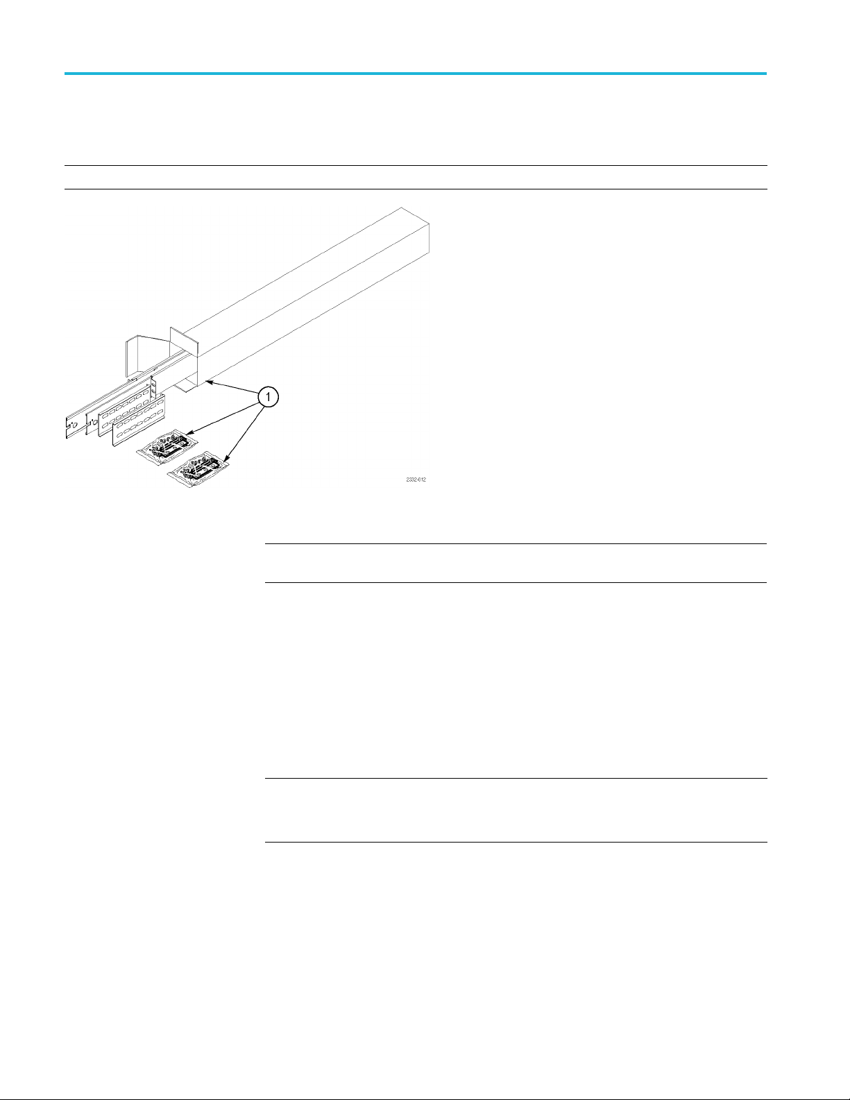
Table 2: Option
Item Quantity Part number Description
1 1 pair 351-1095-00
al accessories (must be ordered separately)
SLIDE ASSY; PAIR, W/STD HARDWARE KIT AND REAR BRACKET
Figure 2: Optional accessories
NOTE. The rack slides are not part of this kit. They are optional, and must be
ordered separately.
Environmental requirements
The fo
specifications and performance verification sections of the manual for your
instrument.
Table 3: Warranted characteristics
Characteristic Description
Temperature
Operating 0 °C to +50 °C (+32 °F to 122 °F)
Nonoperating
Humidity
Operating High: +30 °C to +50 °C, 5% to 60% relative humidity
Nonoperating
llowing environmental characteristics supersede those listed in the
–40 °C to +71 °C (–40 °F to 160 °F)
Low: 0 °C to +30 °C, 5% to 95% relative humidity
High: +30 °C to +55 °C, 5% to 60% relative humidity
Low: 0 °C to +30 °C 5% to 95% relative humidity
4 RMB2020 Rackmount Kit Installation Instructions
Page 7
Kit description
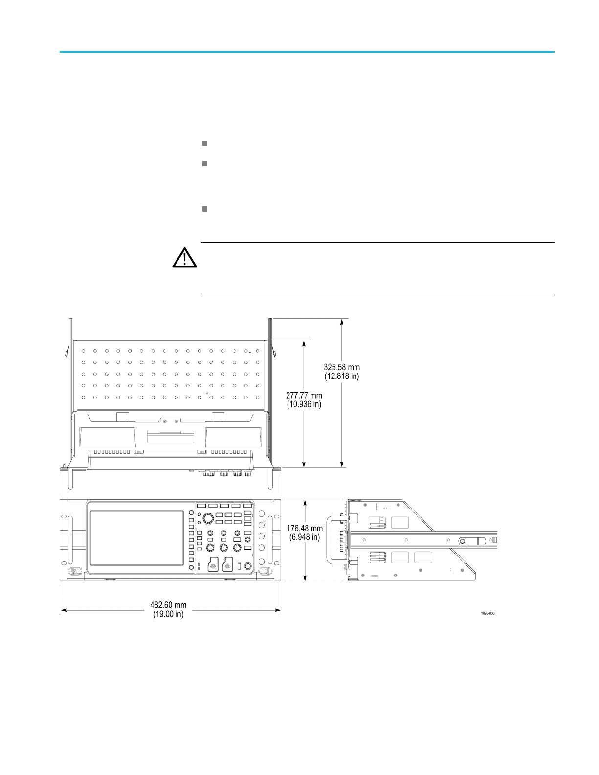
Clearance req
uirements
The rack in which the rack adapted instrument is mounted must provide the
following clearance requirements:
At least 176.48 mm (6.948 in) of vertical space
A minimum width of 488 mm (19.2 in) between the left- and right-front rails
in the rack. If possible, consider allowing at least 50.8 mm (2.0 in) on the
right side and rear of the instrument for adequate airflow.
A minimum inside depth of at least 277.77 mm (10.936 in) depth (from rack
mounting ear to back of instrument)
CAUTION.
instrument with enough clearance for air circulation and accommodation of the
power cord and mounting hardware. Failure to provide these clearances can
result in overheating and can cause instrument faults or failure.
Adhering to these clearance requirements provides the rack-mounted
Figure 3: Instrument with rack adapter installed
RMB2020 Rackmount Kit Installation Instructions 5
Page 8

Installation instructions
Installation instructions
This section contains the procedures needed to rackmount a TBS2xx2 or a
TBS2xx2B series instrument.
Minimum tool and equipment list
The following tools are required to attach the rack-adapter kit hardware, install
cabling har
equipment cabinet. All tools are standard tools that are readily available.
Table 4: Tools required for rackmount installation
Name Description
Screwdriver handle
(magnetic)
No. 2 Phillips or
PoziDriv tip
Straight tip Straight screwdriver tip for slotted screw heads
1/4 inch wrench
Torque driver
dware, and mount the rack-adapted instrument into a standard
Accepts 1/4-inch hexagonal head driver tips
Phillips or PoziDriv-driver tip for number 2 size screw heads
Wrench or nut driver is used to install slides
6.5 in long shaft; accepts 1/4-inch hexagonal head driver tips
6 RMB2020 Rackmount Kit Installation Instructions
Page 9

Install the oscilloscope in the rackmount
This section describes mounting the rackmount parts to the instrument.
1. Install the left and right side brackets to the bottom bracket using three pan
head screws (211-1275-00) on each side. Tighten these screws to 8 in-lb.
(See Figure 4.)
Installation instructions
Figure 4: Assembling the left and right mounting plates
RMB2020 Rackmount Kit Installation Instructions 7
Page 10

Installation instructions
2. Place the oscil
front feet and rear feet in the brackets. The front of the oscilloscope will
extend slightly beyond the front of the rackmount frame. (See Figure 5.)
3. Install top holder into top bracket with two flat head screws (211-0538-00).
(See Figure 5.)
4. Align the guides in the top bracket and the sides and then slide the bottom of
the top bracket into position. (See Figure 5.)
5. Attach the top bracket with 6 of the pan head screws (211-1275-00). (See
Figure 5.)
loscope into the rackmount frame. Position the oscilloscope’s
Figure 5: Installing the instrument in the enclosure
8 RMB2020 Rackmount Kit Installation Instructions
Page 11

Installation instructions
6. Make sure the ve
by rear case and black rubber of handle. (See Figure 6.)
7. Attach the han
split lock washers (210-1547-00) in each handle. Torque these screws to
16 in-lb. (See Figure 6.)
rtical side of top holder inserts into the gap, which is formed
dles, using two of the pan head screws (210-1546-00) and
Figure 6: Installing rackmount handles
RMB2020 Rackmount Kit Installation Instructions 9
Page 12

Installation instructions
Rackmount the oscilloscope without rack slides
If you did not order the optional rackmount slides, you may install the oscilloscope
into an equipment rack by following this procedure:
WARNING. To prevent the instrument from tipping or falling on the installers, this
procedure should be performed by two or more people.
1. Select the appropriate screws for your equipment rack from the kit; 10–32,
12–24, M5, or M6. Assemble them with the recessed and flat washers as
shown:
Figure 7: Rackmount hardware
2. Standard equipment racks use one of two mounting hole spacing methods.
Both methods use mounting holes spaced 0.5 inch apart, separated by a
1.25 inch gap. One method (A) places an additional mounting hole in the
e of the 1.25 inch gap (at 0.625, or 5/8, inch); the other method (B) does
middl
not. (See Figure 8.)
3. Sele
4. Slide the oscilloscope into the equipment rack so that the pin extending back
ct two 0.5 inch-spaced holes in the front rail. Verify that there are
clearances of 1.5 inch above the upper mounting hole and 5.50 inch below the
lower mounting hole. (See Figure 8.)
from the left side, just below the upper mounting hole, goes into the lower of
the 0.5 inch-spaced holes in the front rail. This pin is a locating guide, and
also an aid to holding the oscilloscope in place while securing the oscilloscope
to the instrument rack. (See Figure 8.)
10 RMB2020 Rackmount Kit Installation Instructions
Page 13

Installation instructions
5. Use the screws a
instrument rack.
nd washers from step 1 to attach the oscilloscope to the
Figure 8: Standard rack hole spacing
RMB2020 Rackmount Kit Installation Instructions 11
Page 14

Installation instructions
Rackmount the oscilloscope using optional rack slides
If you ordered the optional rackmount slides, this procedure assembles and installs
the slide-out tracks in the equipment rack, and then installs the oscilloscope in
the rack.
The slide-out tracks permit the oscilloscope to be extended out of the rack for
rear-panel and connector maintenance without removing the instrument from
the rack.
Install track assembly
WARNING. T
operator, install the instrument so that the operator is able to access all of its rear
devices without pushing down on the instrument.
Verify that the rack does not become unstable with the instrument fully extended.
Do not leave the instrument extended when finished accessing the rear panel.
NOTE. The rack hardware kit contains hardware for mounting the instrument in
several configurations. Not all of the hardware in the kit is needed.
1. Remove the front (chassis) section of each of the two tracks.
o prevent the rackmounted instrument from tipping forward on the
Figure 9: Removing front track section
12 RMB2020 Rackmount Kit Installation Instructions
Page 15

Installation instructions
2. Install the lef
the 10-32 x 3/8 inch slotted screws and the nuts with captured lockwashers.
Tighten to 28 in-lb.
t and right side track sections on the instrument using four of
Figure 10: Installing the left and right side track sections
RMB2020 Rackmount Kit Installation Instructions 13
Page 16

Installation instructions
WARNING. To be sure that the rackmount track locks, make sure the track button
latches are or
of the rackmount panel and the left-side latch is located toward the top of the
rackmount panel. If the button latches are not oriented correctly the instrument
could slide from the rack, which could cause personal injury or damage to the
instrument.
iented correctly: the right-side latch is located toward the bottom
Figure 11: Track orientation
14 RMB2020 Rackmount Kit Installation Instructions
Page 17

Installation instructions
Assemble the slide-out
track
1. Measure the dis
2. Align the rear bracket to the right slide-out track as shown.
NOTE. The rea
aligning the bracket and track, be sure to select a pair of holes that mount the
rear bracket so that the flange-to-flange distance matches the distance between
the front rail and rear rail measured in step 1.
3. Using a screwdriver with a number two Pozidriv tip, attach the rear bracket to
the right slide-out track using two screws (10-32) and a bar nut as illustrated.
Leave the screws loose to adjust the overall length of the slide-out track
assembly can be adjusted when installing it in the rack.
4. Step-Repeat steps 2 and 3 to assemble the left slide-out track assembly.
tance between the front and rear rail of the equipment rack.
r bracket has multiple pairs of mount-through holes. When
Figure 12: Slide track assembly
RMB2020 Rackmount Kit Installation Instructions 15
Page 18

Installation instructions
Mount the slide-out track
assemblies
1. Select the moun
the front rail, and verify that there is a 3.25 inch clearance above and below
those mounting holes.
ting position in the rack. Select two 0.5 inch-spaced holes in
Figure 13: Rackmount positions
16 RMB2020 Rackmount Kit Installation Instructions
Page 19

Installation instructions
2. Select the moun
To mount the slide-out tracks with their front and rear flanges outside the
front and rear
installation only if the rails have untapped holes.
To mount wit
method B. This mounting method assumes untapped holes.
ting method according to the rack type:
rails, use the mounting method A. Add a bar nut to the
h front and rear flanges inside the rails, use the mounting
Figure 14: Installation of slide-out track assemblies in rack (top view)
RMB2020 Rackmount Kit Installation Instructions 17
Page 20

Installation instructions
3. Install in rack
Using the method and hardware determined in step 2, attach the right
slide-out tra
fully, but lightly, seated so you can adjust mounting later.
4. Fix the leng
Tighten the screws left loose (step 3 in Assemble the slide-out track
section) to
track assembly.
5. To mount th
left slide-out track assembly.
:
ck assembly to its front and rear rails. The screws should be
th of the slide-out track assembly:
28 inch-lb, to fix the front to rear flange spacing of the slide-out
e left slide-out track assembly, repeat steps 3 and 4 to mount the
Figure 15: Installing the slide-out track to mount stand
18 RMB2020 Rackmount Kit Installation Instructions
Page 21

Installation instructions
Mount the oscilloscope
into the rack
Use the followi
WAR NI NG . To prevent the instrument from tipping or falling on the installers, two
or more people should install this instrument into the rack cabinet.
After completing the installation procedure, the installers should verify that the
instrument and r ack cabinet will not tip forward while the instrument is in the
extended pos
1. Install the instrument:
a. Working from the front of the rack, slide the inner track of each slide-out
track assembly until it extends out the front of the rack. Continue to slide
them out until they lock.
b. Insert the left and right tracks that extend from the rear of the instrument
into the ends of the tracks just extended. Make sure the tracks mounted
on the in
c. Slide the instrument backward until it stops.
d. Push to release the button latches, located on the outside each track, and
continue to slide the instrument all the way into the cabinet.
ng instructions to install and attach the instrument to the rack.
ition.
strument slip inside the inner tracks extended earlier.
2. Level the rackmounted instrument:
a. Tighten the four screws that were left loose at the rear of the rack (step
3inAssemble the slide-out track section), and then pull the instrument
part way out of the rack.
b. Be sure that the four screws that were left loose at the front of the rack
are loose enough to allow the slide-out track assemblies to seek their
mal positions.
nor
c. Retighten the four screws and push the instrument all the way into the
ck. If the tracks do not slide smoothly, readjust the level using the
ra
method just detailed.
hen leveling is completed, tighten the 10-32 screws using 28 inch-lb of
d.W
torque.
RMB2020 Rackmount Kit Installation Instructions 19
Page 22

Installation instructions
3. Attach the inst
a. Select four of the appropriate screws for your equipment rack from the
kit; 10-32, 12
b. Attach the instrument in the rack using the screws selected, with the
recessed wa
rument to the rack:
-24, M5, or M6.
shers and flat washers.
re 16: Securing the instrument to mount stand
Figu
WARNING. To prevent the rackmounted instrument from sliding forward and
causing personal injury or instrument damage, always attach the instrument to
the rack if the rack is moved (for example, if the rack is repositioned or relocated
to another room).
20 RMB2020 Rackmount Kit Installation Instructions
Page 23
Installation instructions
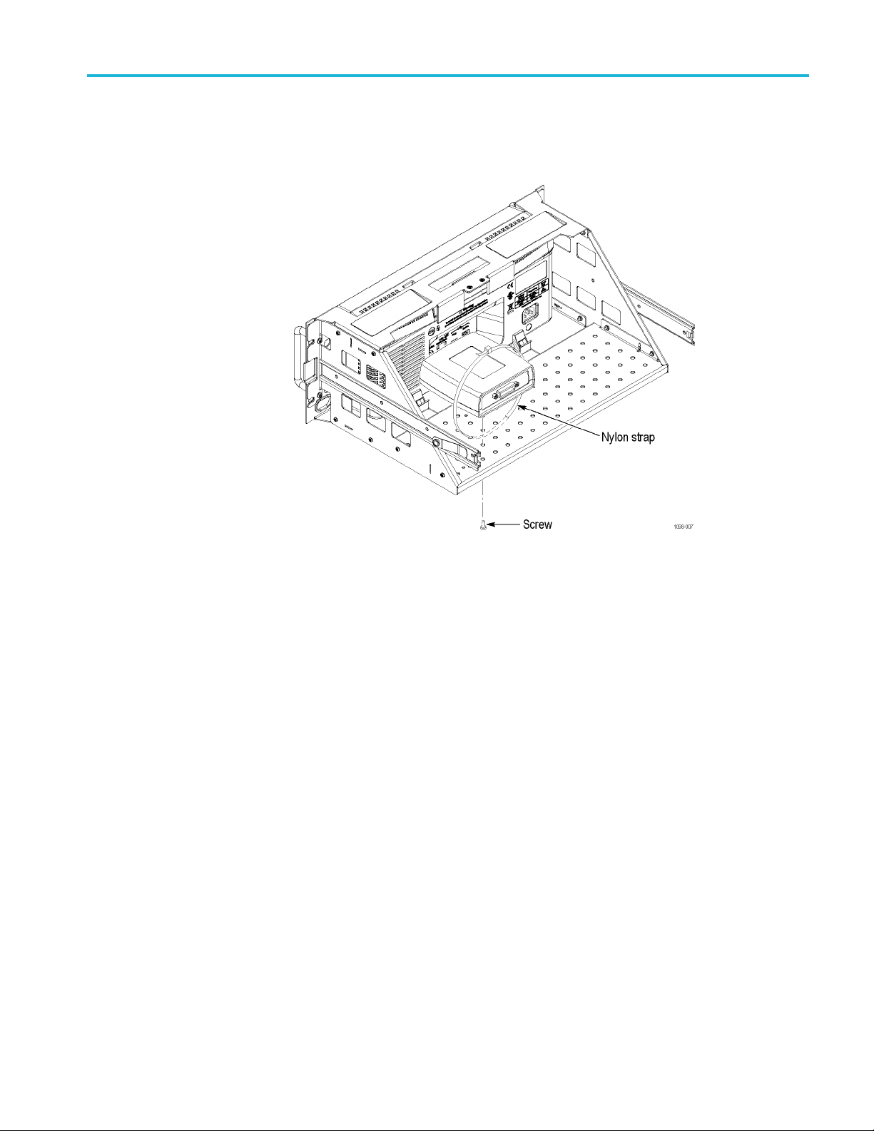
Mounting optional
accessories
The bottom brac
Tek-USB-488 to USA adapter mounted to the back support. Optional accessories
may be mounted with screws or use nylon straps to attach them.
ket has holes for mounting optional accessories. For example,
Figure 17: Mounting optional accessories to bottom bracket
RMB2020 Rackmount Kit Installation Instructions 21
 Loading...