


RFXpress® RFX100
Advanced RF/IF/IQ Waveform Creation and Editing Software for
the AWG5000/B & AWG7000/B Series Generators
PrintedHelpDocument
www.tektronix.com
077-0045-02

Copyright © Tektronix. All rights reserved. Licensed software products are owned by Tektronix or its
subsidiaries or suppliers, and are protected by national copyright laws and international treaty provisions.
Tektronix products are covered by U.S. and foreign patents, issued and pending. Information in this
publication supersedes that in all previously published m aterial. Specifications and price change privileges
reserved.
TEKTRONIX and TEK are registered trademarks of Tektronix, Inc.
Tektronix is pleased to acknowledge Mr Joan Mercade a s the author of portions of this Tektronix RFXpress
Software providing baseband and modulation functionality.
SourceGrid LICENSE, Copyright (c) 2006 www.devage.com, David Icardi
RFXpress RFX100 Online Help Version 2.0, part number 076-0081-02.
Contacting Tektronix
Tektronix,
14200 SW Karl Braun Drive
P.O . B o x 5 0 0
Beaverton, OR 97077
USA
Inc.
For product
In North America, call 1-800-833-9200.
Worldwide, visit ww w.tektronix.com to find contacts in your area.
information, sales, service, and technical support:

Table of Contents
Introduction
Welcome............................................................................................................. 1
Related Documentation ........... .................................. ................................ ............... 1
Conventions.......... ................................ .................................. ............................. 2
Feedback.......................... ................................ .................................. ................. 2
Getting Started
Minimum System Requirements................................. .................................. ............... 3
Ordering RFXpress.................................. ................................ ............................... 3
Installation........................................................................................................... 4
Connection Setups
Setup for RF Signal Generation. .................................. .................................. ......... 4
Setup for IF Signal Generation............................................................................... 5
Setup for AWG IQ Signal Generation....................................................................... 5
Table of Contents
Operating Basics
About Basic Operations............................................................................................ 9
Overview of the Software ........................................................................................ 10
Starting the Software .................... .................................. ................................ ........ 11
Using the Software to Create a Signal........................................................................... 11
Exiting the Software. .... . .... . .... ..... ... . . .... . .... ..... .... . .... . .... ... . . .... . .... . .... ..... .... . .... . .... ... . 12
File Name Extensions and Directories .......................................................................... 12
Applications, Setup Files, and Data Files ..................... ................................ .................. 12
Menus and Toolbars
Menu Bar ...................................................................................................... 13
Standard Toolbar.............................................................................................. 16
Status Bar ...................................................................................................... 17
Waveform List ............ .................................. ................................ .................. 17
Toolbar Options
Select Application ............................................................................................ 19
Signal Type.. .................................. .................................. .............................. 19
Compile................ .................................. ................................ ...................... 20
On/Off.............................. .................................. .................................. ........ 20
Run ................. .................................. ................................ .......................... 20
Dialog Boxes
Open Setup .................................................................................................... 21
Open Data ..................................................................................................... 21
Save Setup............. .................................. .................................. .................... 21
RFXpress RFX100 User Manual i

Table of Contents
Save Data ...... ................................ .................................. .............................. 21
Import Data from a File ...... .................................. ................................ .............. 21
Import from Tektronix Oscilloscope. . .... ..... ..... ... . . .... . .... . .... . .... . .... . .... . .... . .... . .... . .... .. 23
Find Instruments .............................................................................................. 25
Graph......................................... .................................. ................................ 26
Compile Settings.................................... .................................. ........................ 28
Option Installation............................................................................................ 31
Overview ...................... .................................. .................................. ............ 33
Generic Signal Dialog Boxes
Calibration for Generic and Radar Signals................................................................. 35
PRBS Editor ................................. .................................. ................................ 38
Data Source Values ........................................................................................... 39
Modulation File1(Samples).................................... ................................ .............. 40
Modulation File2(Symbols) ................................................................................. 41
Symbol Map........................... .................................. ................................ ...... 42
UWB-WiMedia Dialog Boxes
Calibration for UWB-WiMedia Signal ................................. .................................. .. 45
Marker Mapping .............................................................................................. 48
Tone Nulling. . .... . .... . .... . .... ... . . .... . .... . .... . .... . .... . .... ..... ..... .... . .... . .... . .... . .... . .... . .... 49
Hopping Pattern............................................................................................... 50
Process Preferences........................................................................................... 51
Custom Settings............................................................................................... 53
Frame Payload .......................... .................................. .................................. .. 54
Radar Dialog Boxes
Compile Settings for the Radar Application .............................................................. 55
Creating a Generic Signal
Setup
Single Carrier........................................ .................................. ........................ 59
Multi Carriers ... ................................ .................................. ............................ 60
Editing Carrier Details ....................................................................................... 61
Selecting the Base Data.. ................................ .................................. .................. 63
Modulation for Carriers ...................................................................................... 63
Filter for Carriers . .... ... . . ... . . .... . .... . .... . .... . .... . .... . .... ..... ..... ... . . .... . .... . .... . .... . .... . .... 64
Hopping
Hopping Parameters .......................................................................................... 66
Power Ramping
Power Ramping Parameters ................................................................................. 66
I/Q Impairments
Carrier Leakage for Single Carrier...................... .................................. .................. 67
Quadrature Error for Carriers................................................................................ 68
I/Q Imbalance for Carriers ............................... .................................. .................. 68
ii RFXpress RFX100 User Manual

Nonlinear Distortions for Carriers .......................................................................... 69
Hardware Skew for Carriers......................... .................................. ...................... 69
I/Q Swap for Carriers............................... .................................. ........................ 70
Distortion Addition
Amplifier Distortion for Carriers............................................................................ 70
MultiPath
Multipath Parameters for Carr iers ... . .... . .... . .... . .... . .... ..... . .... ... . . .... . .... . .... . .... . .... . .... . . 71
Interference Addition
Signal Addition for Carriers . .... . .... . .... . .... . .... ..... . .... ... . . .... . .... . .... . .... . .... . .... . .... . .... .. 72
Offset for Carriers ............................................................................................ 73
Sinusoidal for Carriers ... ................................ .................................. .................. 74
Creating a UWB-WiMedia Signal
Conformance Mode ............................................................................................... 77
Custom Mode ............................ .................................. .................................. ...... 77
Conformance Mode Setup
Packet Group Details for Conformance Mode............................................................. 78
Packet Details for Conformance Mode..................................... ................................ 80
Hopping Details for Conformance Mode .................................................................. 82
Custom Mode Setup
Packet Group Details for Custom Mode ............................... .................................. .. 83
Setting PPDU Details ... ..... ... . . .... . .... . .... . .... . .... . .... . .... . .... ... . . ... . . .... . .... . .... . .... . .... .. 84
PLCP Preamble ......................... .................................. .................................. .. 85
PLCP Header ............................ .................................. .................................. .. 86
PSDU............................. .................................. .................................. .......... 87
Packet Sync Sequence.................................. ................................ ...................... 87
PHY Header................................................................................................... 90
MAC Header .................................................................................................. 91
I/Q Impairments
Carrier Leakage for UWB-WiMedia . ................................ .................................. .... 91
Quadrature Error for UWB-WiMedia ...................................................................... 92
I/Q Imbalance for UWB-WiMedia........................................ ................................ .. 92
Nonlinear Distortion for UWB-WiMedia .................................................................. 93
Hardware Skew for UWB-WiMedia.................................. ................................ ...... 93
I/Q Swap for UWB-WiMedia ........................... ................................ .................... 94
Distortion Addition
Amplifier for UWB-WiMedia ............................................................................... 94
MultiPath
Multipath Parameters for UWB-WiMedia .. . . .... . .... . .... . .... ... . . .... . .... . .... . .... ... . . .... . .... . ... 95
Interference Addition
Signal Addition for UWB-WiMedia... . .... ... . . .... . .... . .... . .... ... . . .... . .... . .... . .... ... . . .... . .... . . 96
Offset for UWB-WiMedia ................................................................................... 97
Table of Contents
RFXpress RFX100 User Manual iii

Table of Contents
Gated Noise for UWB-WiMedia.. .................................. ................................ ........ 98
Sinusoidal for UWB-WiMedia ............ .................................. .............................. 101
Real-World Signal Interference ..... .................................. ................................ .... 102
Calibration for UWB-WiMedia Signals
Using Calibration for IF/RF Signals........................................................................... 105
Creating a Radar Signal
Carrier Setup ............................... ................................ .................................. .... 107
Pulse
Pulse Setup .. ................................ .................................. .............................. 107
Pulse Envelope.............................................................................................. 108
Staggered PRI ............................................................................................... 109
Modulation .................................................................................................. 111
Hopping...................................................................................................... 114
Pulse Impairments .. .................................. ................................ ...................... 114
I/Q Impairments
Hardware Skew for Radar ................................................................................. 115
Carrier Leakage for Radar ................................... .................................. ............ 116
Quadrature Error for Radar................................................................................ 116
I/Q Imbalance for Radar ................................................................................... 117
I/Q Swap for Radar ................. .................................. .................................. .... 117
Interference Addition
Signal Addition ... ... . . .... . .... . .... . .... . .... . .... ... . . .... . .... . .... . .... . .... . .... ... . . .... . .... . .... . .. 117
Noise ............... ................................ .................................. ........................ 118
Instrument Control
Controlling an Instrument . .... . .... . .... . .... . .... . .... ... . . .... . .... . .... . .... . .... . .... ..... ..... .... . .... . .. 119
Controlling an Arbitrary Waveform Generator (AWG) . .... ... . . .... . .... . .... . .... .... . .... . .... . .... . .... 120
Connecting to and Controlling an Oscilloscope.. . ... . . .... . .... . .... . .... . .... . ... . . .... . .... . .... . .... . .... 122
Connecting to and Contr olling a Performance Signal Generator (PSG).. . .... ..... . .... ... . . .... . .... . ... 123
Instrument Contol in the Radar Application
Controlling an Arbitrary Waveform Generator from the Radar Application . .... . .... . .... . .... . .... 125
Settings View . .... . ... . . .... . ..... ..... . .... . .... . .... . ... . . .... . ..... ..... . .... . .... . .... . ... . . .... . ..... .. 125
Sequence View ............................................................................................. 126
Trigger Options ............................................................................................. 127
Event Options ............................................................................................... 128
iv RFXpress RFX100 User Manual

Graphing
Zooming Graphs................................................................................................. 129
Pulse Shape....................................................................................................... 12
I(t), Q(t)................... ................................ .................................. ...................... 129
CCDF Plot.................................... .................................. .................................. 130
Spectrum.......................... .................................. ................................ .............. 131
Constellation Plotting .... . .... ... . . .... . .... . .... . .... . .... . .... ..... ..... ... . . .... . .... . .... . .... . .... . .... ... . 132
Eye Diagram ..................................................................................................... 133
Spectrogram...................................................................................................... 1
FFT of Coherent Pulse Interval ................................................................................ 134
Reference
Error Messages
Error Messages for Generic Signal . .................................. ................................ .... 137
Error Messag
Error Messages for Radar.................................................................................. 139
Miscellaneous Error Messages ............................................................................ 143
Miscellaneous Error Messages 2.... .................................. .................................. .. 145
Shortcut Keys .................. ................................ .................................. ................ 146
RFXpress Opt
AWG Spe cifications ............................................................................................. 148
Interleave ....... .................................. .................................. .............................. 148
PRBS Editor Starting Values....... .................................. .................................. ........ 150
Amplifier Distortions............ .................................. .................................. ............ 151
Nonlinear Impairments.................................. .................................. ...................... 151
Image Calib
Types of Modulation ............................................................................................ 153
Frequently Asked Questions ................................................................................... 157
Table of Contents
9
33
es for UWB-WiMedia ................................ .................................. .... 138
AWG Sequence Window-related errors ............................................................. 143
ions and AWG Models ......................................................................... 146
ration................................................................................................ 152
Index
RFXpress RFX100 User Manual v

Table of Contents
vi RFXpress RFX100 User Manual

Introduction Welc ome
Welcome
RFXpress RFX100 is a software application that creates digitally modulated baseband, IQ, IF, RF,
UWB-WiMedia, and Radar signals that can be generated through arbitrary waveform generators (AWG).
This software
arbitrary waveform generators and can also run from an external PC.
runs as an integral part of AWG5000/AWG5000B and AWG7000/AWG7000B series
Using RFXpre
modulation schemes and create single or multi-carrier signals where each carrier can be independently
defined. For each carrier, you can apply impairments such as quadrature error and I/Q imbalance, add
interferences such as sinusoidal interference, and define the graphs to create. Upon compilation, the signal
can be viewed as graphs, sent to an arbitrary waveform generator, and saved for later use. Compilation
options include sending signals directly to the AWG and completely eliminating the wrap-around
effects fo
continuously without any discontinuity or glitch in the tim e, frequency, modulation, or channel coding
domains. Waveform transfer a nd control of the AWG5000/AWG5000B and AWG7000/AWG7000B series
can be performed directly from RFXpress.
Waveforms captured from oscilloscopes and real-time spectrum analyzers can be modified in RFXpress
before they are regenerated.
You can create UltraWideBand WiMedia signals in the Conformance and Custom modes. In the
conformance mode, you can either select a standard setup or define your own setup based on the UWB
standards. In the Custom mode, you can create a customized signal by defining packet parameters and
setting processing preferences. The Calibration feature for the U WB-WiMedia module allows you to
correction files and apply these correction files to channels during compilation.
create
The RFXpress RFX100 radar application supports basic pulse generation of different shapes and
ation types.
modul
ss RFX100 (referred to as RFXpress), you can define baseband I and Q signals with various
und in arbitrary waveform generators. This provides seamless signals that can be played back
Related Documentation
In addition to this RFXpress Online Help, the following documentation is included with the software:
RFXpress Installation Manual (Tektronix part number 077-0160-XX). The installation manual has
information about installing and upgrading the software.
RFXpress User Manual (Tektronix part number 077-0045-XX). The user manual is adapted from
the online help and is available in PDF format.
RFXpress Quick Start User Manual (Tektronix part number 077-0159-XX). The quick start user
manual has information about using the software creating IF/IQ /RF signal output.
For WiMedia standards, please refer to the MultiBand OFDM Physical Layer Specification Version 1.2
(Draft) by WiMedia Alliance.
RFXpress RFX100 User Manual 1

Introduction Conventions
Conventions
The online help uses the following conventions:
When steps require a sequence of selections using the software interface, the ">" delimiter marks each
transition between a menu and an option. For example, File > Save.
DUT refers to the Device Under Test
Three dots (...) following a menu item indicates that the menu item will open a submenu.
The terms "signal" and "waveform" are used interchangeably.
Feedback
Tektronix, I
14200 SW Karl Braun Drive
P.O . B o x 5 0 0
Beaverton, OR 97077
USA
For product information, sales, service, and technical support:
In North Ame
Worldwide, visit www.tektronix.com to find contacts in your area.
nc.
rica, call 1-800-833-9200.
2 RFXpress RFX100 User Manual

Getting Started Minimum System Requirements
Minimum S ystem Requirements
RFXpress when installed on a personal computer runs in the offline mode. The m inim um requirements for
the offline version of the application are listed in the following table.
Table 1: Minimum system requirements
Supported OS Windows XP Professional Service Pack 2.1
Windows Vista Business Edition (English Language)
Minimum Requirements
xxx
You will need:
2.0 GHz or higher
512 MB RAM
15 GB free disk space
Microsoft Internet Explorer 6.01 or higher
.NET 2.0 runtime
1024 x 768 display resolution with 120 dpi font size
TekVisa version 3.3.0.14 or above to communicate with test instruments, such as oscilloscopes,
over LAN. If TekVisa is not already installed in your system, you can download the software from
www.tektronix.com/software.
MATLAB Runtime version 7.6 installed on your instrument.
.NET v2.0 installed on your instrument.
Ordering RFXpress
RFXpress can be ordered as follows:
Table 2: Ordering RFXpress
Part number Description
RFX100
Opt. UWBCF RFXpress plug-In for UWB-WiMedia IQ, IF, and RF
Opt. UWBCT RFXpress plug-in for UWB-WiMedia IQ, IF, and RF custom
Opt. RDR RFXpress plug-in for RADAR signal creation (requires
xxx
Base Software: RFXpress for General Purpose IQ, IF, and
RF signal creation
conformance signal creation (requires RFX100 as
prerequisite)
and conformance signal creation (requires RFX100 as
prerequisite and includes Option UWBCF)
RFX100 as prerequisite)
RFXpress RFX100 User Manual 3

Getting Started Installation
Installation
An installation wizard installs RFXpress. If you have not installed TekVisa version 3.3.0.14 , MATLAB
Runtime version 7.6, and .NET 2.0, you will be notified during installation. You can cancel the installation
any time durin
For details on how to install the software, refer to the RFXpress Installation Manual (Tektronix part
number 077-0
You can uninstall RFXpress in either of the two ways:
From Start > Programs > Tektronix RFXpress > Uninstall RFXpress.
From Add/Remove programs in Control panel.
g the process.
160-XX) available as a PDF on the CD-ROM.
Setup for RF Signal Generation
1. Start the RFXpress installed on the AWG.
2. From the toolbar, select the signal type as IF/RF.
3. Make connections as shown in the figure:
Connect the AWG Ch 1 Analog Output to the DUT where the R F Signal must be fed.
When using t
4. Click Compile. The waveform is compiled according to the default settings in the Compile Settings
window. The compiled waveform is displayed in the Waveform List. This IF/RF waveform will be
transferred to the AWG channel (Ch1) and this can also be seen in the Instrument Control > AWG tab.
he Interleave mode, the RF output should be taken from Interleave Output as shown.
5. ClickOn/OfftoturnonthechannelCh1.
6. Click Run to generate the signal on the AWG.
4 RFXpress RFX100 User Manual

Getting Started Setup for IF Signal Generation
See also:
C
alibration (see page 105)
Find Instruments (see page 25)
Setup for IF Signal Generation
1. Start the RFXpress installed o n the AWG.
2. From the toolb
3. Connect the AWG Ch 1 Analog O utput to the DUT where the IF Signal must be fed.
4. Click Compile. The waveform is compiled according to the default settings in the Compile Settings
window. The compiled waveform is displayed in the Waveform List. This IF waveform will be
transferre
5. Click On/Off to turn on the channel Ch1.
6. Click Run to generate the signal on the AWG.
See also:
C
alibration (see page 105)
Find Instruments (see page 25)
Setup for A
1. Start the R
2. From the toolbar, select the sign al type as IQ.
ar, select the signal type as IF/RF.
d to the AWG channels (Ch1) and this can also be seen in the Instrument Control > AWG tab.
WG IQ Signal Generation
FXpress installed on the AWG.
3. Make connections as shown in the figure:
Connect the AWG Ch1 Analog Output to the DUT where the I Signal must be fed.
Connect the AWG Ch2 Analog Output to the DUT where the Q Signal must be fed.
RFXpress RFX100 User Manual 5

Getting Started Setup for AWG IQ Signal G eneration
NOTE. Both ca bles must be the same length, otherwise you would need to deskew them.
4. Click Compile. The waveform is compiled according to the default settings in the Compile Settings.
The compiled waveform is displayed in the Waveform List. This waveform will be transferred to the
AWG channels (Ch1 and Ch2). This can also be seen in the Instrument Control > AWG tab.
5. ClickOn/OfftoturnonthechannelsCh1andCh2.
6. Click Run to generate the signal on the AWG.
Setup for AWG IQ Signal Generation with External Modulator
1. Start the RFXpress installed on the AWG.
2. Select the Signal type as IQ.
3. Make connections as shown in the figure:
Connect the AWG and Agilent performance signal generator® (E8267D with Option 015) through
LAN or GPIB.
Connect the AWG Ch1 Analog Output to the A gilent performance signal generator’s (PSG® )
external I Input (in the rear panel).
Connect the AWG Ch2 Analog Output to the A gilent performance signal generator’s (PSG®)
external Q Input (in the rear panel).
Connect the PSG’s RF output from the front to the DUT.
6 RFXpress RFX100 User Manual

Getting Started Setup for AWG IQ Signal G eneration
NOTE. Both cables must be the same length, otherwise you would need to deskew them.
4. Click Compile. The waveform is compiled according to the default settings in the Compile Settings
window. The compiled w aveform is displayed in the Waveform List. This waveform will be transferred
to the AWG channels (Ch1 and Ch2 ). This can also be seen in the Instrument Control > AWG tab.
5. ClickOn/OfftoturnonthechannelsCh1andCh2.
6. Click Run to generate the signal on the AWG.
See also:
ation (see page 105)
C
alibr
Find Instruments (see page 25)
RFXpress RFX100 User Manual 7

Getting Started Setup for AWG IQ Signal G eneration
8 RFXpress RFX100 User Manual

Operating Basics About Basic Operations
About B asic Operations
The basic operations section describes the software, tells how to start the software, use the menus and
toolbars, and describes the dialog boxes.
In this online help, all menu selections are indicated with Menu name and Menu options separated by
">". Youcanaccessacommandoramenuoptioninmore than one way. Several main menu options are
available in
which open with a right-click, are provided for editing, creating and viewing graphs, importing data from a
file or a Tektronix oscilloscope, and transferring a waveform to an arbitrary waveform generator.
Some dialog boxes also have a Help button that displays help for that dialog box.
a toolbar that you can use instead of selecting the option from the main menu. Shortcut menus,
Detailed op
Radar, Calibration for WiMedia Signals, Instrument Control, and Graphing. The References section lists
Error Messages, Shortcut Keys, and provides a note on Interleaving and Types of Modulation.
The following figure shows the application screen, the menu, the toolbar, and other elements of t he
user interface.
erations and parameters are described in the sections on Generic Signal, UWB-WiMedia,
RFXpress RFX100 User Manual 9

Operating Basics Overview of the Software
Overview of the Software
RFXpress is a software application that creates digitally modulated baseband, IQ, IF, RF, UWB-WiMedia,
and Radar signals that can be generated through arbitrary waveform generators (AWG). This softw are
runs as an integral part of AWG5000/AW G5000B and AWG7000/AWG7000B series arbitrary waveform
generators and can also run from an external PC.
Features of RFXpress
Baseband data generation: Define baseband I and Q signals using a variety of modulation schemes
such as, BPSK, QPSK, PI/4 QPSK, OQPSK, SDPSK, 8-PSK, O-8PSK, QAM16, QAM32, QAM64,
QAM128, QAM256, QAM256, QAM512, QAM1024, GMSK, 2-FSK, 4-FSK, 8 -FSK, 16-FSK,
32-FSK, AM, FM, and PM.
Multi-carrier setup: Define multiple RF/IF carriers in a single waveform. Each carrier can be
independently defined with parameters such as carrier frequency, symbol rate, modulation type, and
baseband filters.
Single or multiple pulse groups to form a pulse train: Each pul
with various predefined pulse shapes and user defi ned shapes for a pulse group.
Allows you to apply various modulation schemes or define your own.
Allows you to have Pulse- to-Pulse hopping within a pulse group and to apply impairments like Edge
Jitter, Width Jitter, Overshoot, Ripple and Droop on a pulse group.
IQ impairments: Apply impairments including quadrature error and quadrature imbalance.
Generate the following graphs:
Frequency Domain: Spectrum
I v Q: Constellation
Time Domain: I(t) and Q(t) vs. time, and Pulse shape
Statistical: CCDF and Eye Diagram
Time vs Frequency: Spectrogram and Coherent Pulse Interval
Distortion measurement for system calibration: To maintain system integrity and coherency with
Amplitude, Phase inband flatness, and skew between separate channels. The setup includes capturing
data from a TDS oscilloscope and a real-time spectrum analyzer and downloading the data to generate
the correction data.
Noise/interference generation and addition: Generate and add interference for waveforms. Generate
gated noise on specific frames designated by the user.
se group can be independently defined
Capture and Replay: Waveforms captured from oscilloscopes and real-time spectrum analyzers can
be modified in RFXpress before they are regenerated.
10 RFXpress RFX100 User Manual

Operating Basics Starting the Software
Wrap around: RFXpress completely eliminates all the wrap-around effects found in arbitrary
waveform generators, providing seamless signals that can be played back continuously without any
discontinuit
Connectivity between AWG, oscilloscope, and Agilent Performance Signal Generator® (PSG).
The ability to identify and connect to a Tektronix Arbitrary Signal Generator (AWG), a Tektronix
oscilloscope, and the Agilent PSG®, and
the AWG sequence mode is to optimize the memory and create large number of pulses.
y or glitch in the time, frequency, modulation, or channel c oding domains.
to configure their setups remotely. The radar application uses
Starting the Software
From the Start menu, click All Programs > Tektronix RFXpress > RFXpress. You can also double-click
the RFXpress shortcut on the desktop.
You can use the software in three modes:
RFXpress on any AWG5000/AWG5000B or AWG7000/AWG7000B series instrument. In this case,
the software automatically detects the AWG software. You can transfer data directly to the AWG. The
status bar shows "AWGXXXX Online".
RFXpress on a PC with the AWG software running in the offline mode. In this case, the AWG software
has to be started before starting RFXpress. You can transfer data to the AWG offline software. The
status bar shows "AWGXXXX Offline".
RFXpress on a PC without the AWG software. In this case, the software does not detect the AWG
software, and you cannot transfer data to the AWG (although you can create and store the waveform
for later use). The status bar shows "AWGXXXX Not Available".
UsingtheSoftwaretoCreateaSignal
Using RFXpress, you can generate a signal as follows:
1. Select an application or module: Generic Signal, UWB-WiMedia, or Radar.
2. Select the signal type: IF/RF or IQ.
3. For a Generic signal, select the number of carriers: Single or Multi-carrier. For a UWB signal, select
the m od e: Conformance or Custom. For a Radar signal, select the number of pulses.
4. For a Generic signal, define the carrier parameters: Frequency, Modulation, Amplitude, Filter and
others. For a UWB signal, select the setup and define the selected packet group and packet parameters.
For a Radar signal, select the pulse envelope, frequency, and other pulse par ameters.
5. Select the compilation options and compile the signal.
You can also specify the graphs that you want to create and view them in the Graph Preview window. You
can transfer the signal to an arbitrary waveform generator in the I nstrument Control window. Importing
files and replicating waveform files work with only the following instruments:
RFXpress RFX100 User Manual 11

Operating Basics Exiting the Software
Oscilloscopes: Tektronix TDS6000, DPO70000, and DPO7000 series
Arbitrary Waveform Generators: Tektronix AWG400, AWG500, AWG600, and AWG700 series
Real-time Spectrum Analyzers: Tektronix RSA3000 and RSA60000 series
Exiting the Software
Select File > Exit to exit the application. If you have not saved the waveforms, you are prompted to do so.
File Name Extensions and Directories
The software uses the following file name extensions:
Table 3: File name extensions and their descriptions
File name extension Description
.rfs Setup file of the selected application
.rfd Data file of the waveform (generic signal and ultra wide
band signal)
.smp
.rfc Correction file
xxx
Symbol file
The software uses the following directories:
Table 4: Directory names and their descriptions
Directory Description
C:\Program Files\Tektronix\RFXpress\System Contains the application files and executables
C:\Program Files\Tektronix\RFXpress\Documentation Contains the related documentation as text and PDF files
C:\Program Files\Tektronix\RFXpress\Samples Contains sample waveform files
xxx
Applications, Setup Files, and D ata Files
An application is a module that you can use to create specific types of waveforms, for example Generic
Signal and UWB-WiMedia. Applications that are available but have not been purchased appear in the
Application list but are disabled.
You can only have one Setup File (.rfs) open at a time and only one application in use at a tim e. If you
change the application, you will be prompted to save the open file.
12 RFXpress RFX100 User Manual
Operating Basics Menu Bar
Selecting an application: In the Select field, select an application from the list. When you select
an application (Generic Signal, UWB-WiMedia, or R adar), the default settings are displayed for the
currently sel
Setup File (.rfs): A Setup File is a collection of settings that describes a single or multiple waveforms.
Once you compi
Compiled data files for the current session appear in the Waveform List. After you select the Application,
a default Setup File opens automatically. If a setup file is open with unsaved c hanges and you try to
create a new file or change applications, you are prompted to save the file. Toopenanexistingsetup
file, select File > Open Setup.
The rfs file content varies depending on the selected application (Generic or UWB-WiMedia). By default,
thenameoftherfsfile is derived from the application name.
Data F ile (.rfd): You can save a compiled Setup File as a Data File using File > Save Data or Save Data
As. Files that you import from other instruments become data files. Select File > Save or Save As to save
these data files. To open an existing data file, select File > Open Data.
ected application.
le the setup file (using Waveform > Compile), you can save the file as a Data File (.rfd).
NOTE. Eac
information and sampling rate.
Menu Bar
The RFXpress menu has the following items:
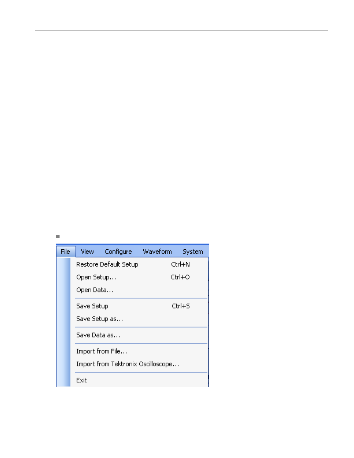
File
hrfdfile can store one of the three formats: IF/RF, I, and Q. An rfd file stores the version
RFXpress RFX100 User Manual 13

Operating Basic s Menu Bar
Use the File menu to:
Restore the default setup for the currently active application
Create new waveform setups
Open, close and save waveform setups (.rfs format)
Open, close and save data files (.rfd format)
t data from a file (created by another software)
Impor
Import data from a Tektronix oscilloscope
Exit the software
Vie w
Use the View menu to:
View the Standard toolbar
View the Status toolbar
Configure
Use the Configure menu to:
Select an application: Gen eric Signal, UWB-WiMedia, or Radar. UWB-WiMedia and Radar
are available only if they have been purchased
Open the Find Instruments dialog box to m ake instrument connections
Waveform
14 RFXpress RFX100 User Manual

Operating Basics Menu Bar
Use the Waveform menu to:
Compile the currently active Waveform Setup
Set Compilation options
Open the Graph Setup dialog box to select the graphs
System
Use the System menu to:
Run
Stop
Turn all channel outputs on o r o ff
Open the Ca
Window
libration dialog box and set the parameters to calibrate the signal
RFXpress RFX100 User Manual 15

Operating Basic s Standard Toolbar
Use the Window menu to:
View the Waveform List window
Preview the Graphs
Open Instrument Control window
Open the Overview window
Close all windows
Help
Use the Help menu to:
Open the online help
Displayhelpspecific to the currently active application
Display technical support on the Tektronix Web site
Display information about the application, such as version number
Standard Toolbar
The Standard toolbar is always displayed by default. Select View > S tandard toolbar to hide or show
the toolbar.
The Standard toolbar has the following options that you can select:
Select Application (see page 19)
Signal Type (see page 19)
Calibration (see page 35) Calibration for Generic Signal
Overview (see page 33)
Find Instruments (see page 25)
16 RFXpress RFX100 User Manual

Operating Basics Status Bar
Graph (see page 26)
Compile (see page 20) and Compile Settings (see page 28)
Status Bar
The S tatus Bar is always displayed by default. Select View > Status Bar to hide or show the status bar.
The status bar shows the selected application, the AWG mode, and the active waveform names. The
status of calibration (On/Off) is also displayed.
Waveform List
Window > Waveform List
The Waveform List is a floating window and can be moved anywhere in the display area. By default it
opens in the leftmost area of the display window. The Waveform List window can be kept open by
pushing the pin in the top right corner, or closed and opened as you like. To view the waveform list,
from the menu select Window > Waveform List.
After you select a signal to generate and set the parameters for it, you must compile it to create the data.
Once you compile a signal (using Compile from the toolbar), waveform data is created and added to the
waveform
data. The maximum number of w aveforms that can be displayed in the waveform list is 13,000. When
the number of waveforms exceeds this limit, a warning message appears: Number of waveforms is over
the maximum limit of 13,000.
To save a waveform that is available in the list, select the waveform and select File > Save Data or Save
Data As. You can also right-click the selected waveform and choose Save Data As. The compiled
waveform or data file is saved as a data file (.rfd) in the specified location. The data files are stored in the
path where the application is installed.
NOTE.
compile the waveform again from the setup, if you have saved the setup using File > Save Setup or Save
Setup As. The setup file is an rfs file.
You can select the following options from the shortcut menu:
list. The Waveform list displays the Name, Length, Sampling Rate and Format of the waveform
If you close the software without saving the compiled waveform, the waveform is lost. You can
RFXpress RFX100 User Manual 17

Operating Basic s Waveform List
Table 5: Shortcut menu options and their description
Selection
Description
Send to AWG Enabled only if the AWG software is running and when a
waveform is selected. Sends the selected waveform data
to an Arbitrary Waveform Generator. Select the channel to
which to send the data.
Show Graph Enabled only when a waveform is selected. Plots a graph of
the selected type: Frequency Spectrum, Time Domain and
CCDF. You can also select G
raph Settings... (see p age 26)
and choose the graphs from those available.
Save Data As... Enabled only when a waveform is selected. Saves the
selected waveform data as a .rfd file in the specified name
and location.
Import from File... (see page 21) Imports data into the software from a file. Choose the file
and location from which to import data.
Import from Tektronix Oscilloscope... (see page 23) Imports data from a Tektronix oscilloscope that is connected
to the instrument on which the software is running.
Delete All
Enabled only when a waveform or waveforms are available
in the Waveform List. Deletes all the waveforms shown in
the waveform list.
Delete
Enabled only when a waveform is selected. Deletes the
selected waveform.
Rename...
Enabled only when a waveform is selected. Opens a dialog
box that allows you to enter a waveform name.
xxx
You can also drag and drop a waveform from the Waveform List to Instrument Control. When you drag
and drop a waveform, the sampling rate is automatically set in the instrument.
The Rename…, Save As… and Delete buttons appear at the bottom of the Waveform List. These buttons
are available only when a waveform is selected.
18 RFXpress RFX100 User Manual

Operating Basics Select Application
Table 6: Waveform list buttons and their description
Selection
Rename...
Save... Saves the selected waveform as an .rfd file.
Delete
xxx
Description
Opens a dialog
waveform.
Deletes the selected waveform.
box and allows you to rename the selected
Generating Graphs
In the shortc
and CCDF. Not all the graphs are available for all waveform formats and all applications. The following
table lists the availability of the graphs for various waveform formats.
Table 7: Waveform formats and available graphs
format
When both I and Q
waveforms are selected
When I waveform is
selected
When Q waveform is
selected
When IF/RF waveform is
selected
xxx
For the Radar application, the available graphs are Spectrum, Spectrogram, CPI, I Vs Time, and Q Vs time.
ut menu, from the Graph option you can select the following graphs: Time Domain, Spectrum,
GraphsSelected waveform
CCDF Spectrum
Available Available Not available
Not available Not available Available
Not available Not available Available
Not available Available Available
Time domain
Select Application
Configure > Select Application
Before you create a new Waveform S etup and Setup File, you must identify the application. Do this by
clicking on the Application fi eld and selecting either Generic Signal, UWB-WiMedia, or Radar. The
default settings for the currently selected application will be displayed.
NOTE. The UWB-WiMedia Custom Mode and Radar are enabled only if you have purchased the options.
Signal Type
Set the signal type from the drop-down list to either IF/RF or IQ. Another way to select the signal type is
by using the C
RFXpress RFX100 User Manual 19
ompile Settings (see page 2 8) dialog box.

Operating Basic s Compile
Compile
Waveform > Compile
To compile a currently active waveform:
1. Click Compile in the Standard toolbar. The waveform is compiled and displayed in the Waveform List.
2. From th e Waveform List (see page 17), you can select Send to AWG, Show Graph, Save Data as,
On/Off
Click the On/Off button to turn on or turn off the arbitrary waveform generator (AWG)
channel output.
Run
Click the Run button to turn on or turn off the Run state of the arbitrary waveform generator
(AWG). If the application is running on an AWG or using an offline mode of the AWG software, the
compiled waveform is directly output to the channel. The channel is turned on and generates the signal.
The signal generation is indicated when the Run button changes to green.
Delete, or Rename the waveform.
20 RFXpress RFX100 User Manual

Operating Basics Open Setup
Open Setup
File > Open Setup
Youcanopenasetupfile from the selected location. All files have the file name extension .rfs.
Open Data
File > Open D ata
You can open a data file from the selected location. All files have the file name extension: .rfd.
Save Setup
File > Save Setup, File > Save Setup As...
You can save the setup file in any of the following formats: .rfs and .txt.
Use File > Save Setup to save an existing setup file with the same name. If you are saving the setup for the
first tim e, the Save Setup option works exactly as the Save Setup As... option.
Use File > Save Setup As... to save the setup file with another file name.
Save Data
File > Save Data, File > Save Data As...
You can save the data file in either .rfd or .txt format. You must compile a setup before you can save the
data. If you try to save a setup as data without compiling, you are prompted to compile the setup.
UseFile>SaveDatatosaveanexistingdatafile with the same name. If you are saving the data for the
first tim e, the Save Data option works exactly as the Save Data As... option.
UseFile>SaveDataAs... tosavethedatafile with another file name.
ort Data from a File
Imp
e > Import from File
Fil
RFXpress RFX100 User Manual 21

Operating Basics Import Data from a File
You can import a waveform file created in another software, and import the resulting waveform into
RFXpress. To import data from a file, select File > Import from file. This dialog box is displayed. Navigate
to the directo
ry of choice and select the file to import.
You can impor t files of the following types:
.wfm from oscilloscopes and arbitrary waveform generators
.iqt from real-time spectrum analyzers (RSA3000 series)
.tiq from real-time s pectrum analyzers (RSA6000 series)
.pat from arbitrary waveform generators
.isf from oscilloscopes
22 RFXpress RFX100 User Manual

Operating Basics Import from Tektronix Oscilloscope
.csv (comma separated file)
.txt (text file)
.mat (MATLAB) file
The following options are available:
Table 8: File import options and their description
Selection
Data Type: I Data, Q Data, IF/RF Data Select the data type to specify the type
CSV, Txt Format Specifies the parameters contained in
Overwrite waveform in list
Set as baseband signal
xxx
Description
of data contained in the file. Enabled
only when the file formats are .csv
and .txt
the csv or text file:
Time, Volt <cr><lf> (TDS CSV format)
Points, Volt <cr><lf>
Volt <cr><lf>
Volt <cr><lf>, AWG710 format
Enabled only when the file format is
.csv or .txt.
When selected, overwrites the
waveform present in the waveform list
without any warning.
When selected, replaces any existing
carriers with two carriers representing
the baseband signal. This option is
available only when an iqt or tiq file is
selected for import and the selected
application is Generic Signal.
A MATLAB (.mat) file should meet the following conditions:
Default value
IData
Time, Volt <cr><lf> (TDS CSV format)
Disabled
Disabled
It should contain a sampling rate and a variable with ‘n’ sample p
oints or values (n > 1).
The sampling rate s hould be of the format 1 x 1 and the points should be of the format 1 x n.
For example,
SamplingRate = 15e9
SamplePoints = [ 0.5 0.3 0.2 0.7 ….]
Import from Tektronix Oscilloscope
File > Import from Tektronix Oscilloscope
RFXpress RFX100 User Manual 23

Operating Basics Import from Tektronix Oscilloscope
You can import a waveform file from a Tektronix oscilloscope that is connected to your instrument into
RFXpress. To do this, select File > Import from Tektronix Oscilloscope. This dialog box is displayed.
A table displays a list of oscilloscopes on the network. Select an oscilloscope in the table a nd click
Connect to connect to it. You can connect to more than one oscilloscope at a time. Click Disconnect to
disconnect from an oscilloscope.
For a connected oscilloscope, you can set the following parameters:
Table 9: Waveform import options and their description
Selection
Data Source Select the data from which to acquire
Waveform Type Select the type of waveform: I, Q, or
Waveform Name Specify the waveform name. The
Acquisition Mode
Record Length
xxx
Description
the waveform data: Ch1 to Ch4,
Math1 to Math4, and Reference1 to
Reference4.
RFIF.
imported waveform is saved in the
specified name.
Set the acquisition mode to one of
the following: Samples, Peak De
Envelope, or Average.
Displays the record length of the
selected oscilloscope. Change the
record length by entering a ne
in the field.
tect,
w value
Default value
Ch1
I
N/A
Samples
N/A
24 RFXpress RFX100 User Manual

Operating Basics Find Instruments
Click Acquire to import the data. The specified waveform name is used to list the waveform in the
Waveform List.
Find Instruments
Configure > Find Instruments
You can find instruments on the network and connect to them.
1. Click Find Instruments to find other instruments on the network. The following dialog box opens. A
table lists the instruments found along with the Name of the instrument, Model, Status (connected or
not), and the Connection type (Ethernet or GPIB).
2. Select an instrument from the table. Use the following buttons to:
Table 10: Find instruments options and their description
Button Description
Connect Connect to the instrument selected in the table. Connect
is enabled by default if an instrument is highlighted in the
disabled if no instrument is highlighted.
table;
Disconnect
Refresh Refresh the list of instruments.
Import... (see page 23) Open the Import from Tektronix O scilloscope dialog box to
xxx
3. Click
Connect to connect to the selected instrument. The Status provides the current status during the
nect the connected instrument. Enabled only if
Discon
highlighted instrument is connected.
select a file to import.
refresh operation: Searching Instruments or Ready.
RFXpress RFX100 User Manual 25

Operating Basic s Graph
Graph
Waveform > Show Graph or Graph Settings
The software allows you to select the types of graphs before creating them. The graphs are displayed in
two modes: as a set in a small window (for preview), and as individual graphs in large independent
windows. At any time, a maximum of three graphs can be displayed in the small view.
To specify the graphs to create, click Graphs in th e toolbar or Waveform > Graph from the menu. The
Graph Setup dialog box opens.
Follow these steps to select the graphs to create:
1. Highlight a folder on the left. The graphs are grouped into the following folders: Frequency Domain, I
vs. Q, Statistical, and Time Domain.
2. Highlight a graph from Available Graphs on the right. Click Add to add the graph to the Selected
Graphs a rea or drag and drop the graph to the Selected Graphs area.
The following folders and graphs are available:
Frequency Domain: Spectrum
I Vs Q: Constellation
tical: CCDF and Eye Diagram
Statis
Time Domain: I & Q vs. time, and Pulse shape
Time vs Frequency: Spectrogram and Coherent Pulse Interval
The Spectrum (Frequency Domain), I & Q vs. time (Time Domain), and Spectrogram (Time vs
Frequency) graphs are available for the Generic, UWB-WiMEdia, and Radar applications. However,
the Coherent Pulse Interval is specific to the radar application.
26 RFXpress RFX100 User Manual

Operating Basics Graph
NOTE. Once three graphs are added to Selected Graphs, the software will not allow you to add any more
graphs. You m ust remove a graph before you can add another graph.
To remove a graph, highlight a graph in Selected Graphs and click Remove.
3. Click OK to view the graphs. the graphs are displayed in the Graph Preview tab. If you have selected
fewer than three graphs, the other window (or windows) will be empty.
You can also create graphs from the W
1. Select a waveform from the Waveform List.
2. Right-click to view the shortcut menu.
3. Select S
independent window.
how Graph and select the type of graph to generate. The graph is displayed in a large
aveform List (see page 17) as follows:
Graph Preview
Graph Preview is a tab in a window that is shared with Instrument Control. Click the Graph Window tab to
open it as a docked window.
When RFXpress first launches, Graph Preview is closed by default.
Large Graph Windows
1. In the Graph Preview tab, c lick Maximize to view a graph in a larger w indow. The selected graph is
displayed in a larger window.
RFXpress RFX100 User Manual 27

Operating Basic s Compile Settings
NOTE. When no graphs are selected, Maximize is not available.
The Zoom In and Zoom Out buttons are available in the following graphs: Spectrum, and I(t) Q(t)
Cursors, Cursor Readouts and the difference (Delta) between the cursors are available for the following
graphs: Spectrum, I(t) Q(t), and CCDF.
2. Click to close the graph and return to the small view.
Graphs from External Data
You can import data from a file (File > Import from File) and create graphs using the data. The imported
file is displayed in the W
andclickSh
ow Graph.
aveform List (see page 17). Select the file from the Waveform List, right-click,
Compile Settings
Waveform > Compile Settings
To specify compilation settings for the currently active Waveform Setup, click Compile Settings. This
dialog box is displayed.
28 RFXpress RFX100 User Manual

Operating Basics Compile Settings
RFXpre
on the signal format selected.
For e
The Correction Files option is available only when the selected application is UWB-WiMedia and the
Comp
ss supports generation of two signal types. The number of waveforms generated varies depending
and signals (IQ format): When the IQ signal format is selected, two baseband wa veforms I and
Baseb
Q are generated. You must specify the names of each waveform.
nals (IF/RF format): When the RF signal format is selected, the baseband waveforms I and Q are
RF sig
also generated. So after com piling, three different files are generated.
xample, if the waveform name is Test, the generated waveforms are: Test_I, Test_Q, and Test.
ile Button Prefs option is available only when the AWG software is detected.
RFXpress RFX100 User Manual 29

Operating Basic s Compile Settings
Table 11: Compile settings options and their description
Selection Description Range, Default
Waveform leng
Samples)
1
th (Symbols,
Specifies the t
ime domain length of
the resulting waveform. It can be
Determined by the maximum
waveform memo
expressed in Samples or Symbols.
Automatic
Calculates the waveform length
automatical
ly, based on the setup
Enabled
parameters and the AWG model. To
enter the waveform length, disable
this option.
Correction F
When compil
to these channels: Ch1, Ch2, Ch3,
Ch4
iles
ing apply correction files
Available a
nd enabled for each
channel on the instrument. For
two-channel instruments, only Ch1
and Ch2 are v
isible. When a channel
Disabled
is selected, the corrections are applied
from the file during compilation. If
no file exis
ts, you are prompted to
either create a correction file in the
Calibration window, or compile without
applying
Signal Fo
rmat
IF/RF Sets the s
IQ Sets the s
2
Oversamp
Automatic
ling
Specify t
Calcula
correction files.
ignal format to IF/RF.
ignal format to IQ.
he oversampling value.
tes the oversampling
N/A
N/A
Automatic
Enabled
automatically, based on the setup
parameters and the AWG model. To
e oversampling value, disable
enter th
this option.
RF Waveform Name Enter the name of the waveform to be
Waveform1
generated after compilation. Uses the
name en
tered here for the generated
RF waveform.
I Waveform Name Enter the name of the I waveform
Waveform1_I
to be generated after compilation.
he name entered here for the
Uses t
generated I waveform.
Q Waveform Name Enter the name of the Q waveform
Waveform1_Q
to be generated after compilation.
he name entered here for the
Uses t
generated Q waveform.
Compile Button Prefs
Compiles and sends to Compiles the currently active
Ch1
waveform setup and sends it to the
ified channel.
spec
value
ry of the instrument.
30 RFXpress RFX100 User Manual

Operating Basics Option Installation
Table 11: Compile settings options and their description (cont.)
Selection Description Range, Default value
Compile only Compiles the currently active
N/A
waveform setup.
Normalization
Mode
Select the normalization mode from
Auto
the following: Auto, Manual.
You can normalize a waveform such
that all points on it lie between +1
and –1.
Division factor
Enabled when the Normalization
0.01 to 100, 1
Mode is Manual. Specify the division
factortousetodividethewaveform
values.
Adjust for Wrap-Around When selected, adjusts the waveform
Enabled
for wrap around during oversampling.
When cleared, the following message
appears: The signal generated from
the AWG might have wrap-around
artifacts in continuous mode.
Overwrite waveform in list
When selected, overwrites any
Enabled
existing waveform of the same name
in the waveform list. When this option
is disabled, you are prompted to enter
a waveform file name.
xxx
1
If the Waveform Length is expressed in symbols, the number of samples is approximately given by the product of the number of symbols and the
sampling rate divided by the symbol rate.
2
For IF/RF signals, the sampling rate is approximately the product of the maximum carrier frequency and the oversampling. For IQ signals, the
sampling rate is approximately the product of the anchor carrier symbol rate and the oversampling. For UWB-WiMedia signals, sampling rate is
approximately the product of the highest band group centre frequency and the oversampling.
Click C ompile to compile the waveform. A progress bar is displayed during com pilation. You can abort
the compilation by clicking Cancel.
NOTE. When Adjust for Wrap-Around is enabled and the waveform length is set in samples, the symbol
rate of the compiled waveform may be close to, and not exactly the same as, the value specified in the
Setup tab. Similarly, when the waveform length is set in symbols, the carrier frequency of the compiled
waveform may be close to, and not exactly the same as, the value specified in the Setup tab.
Option Installation
System > Option Installation...
You can use the RFXpress application to generate wav eforms but you cannot transfer the waveform unless
you enable the function w ith a option (license) key.
RFXpress RFX100 User Manual 31

Operating Basics Option Installation
Click System > Option Installation.... This dialog box is displayed.
Table 12: Option installation information and their description
Selection
User Name Enter the user name.
Serial Number
Option Key String
Option Information The option information is displayed in the table.
xxx
Description
he serial number that is provided along with the
Enter t
software.
he option key string that is provided along with the
Enter t
software.
ClickCopyOptionInfotocopytheinformationinthetable to the clipboard. Click Apply to apply the
entered values.
32 RFXpress RFX100 User Manual

Operating Basics Overview
Overview
Window > Overview
Click Window > Overview to open the overview window. A block view of the active waveform appears
in a new window. This window is a floating window and can be moved around the screen. Each larger
grouping in the diagram corresponds to a tab.
The On/Off button in the upper right corner of each block in a block corresponds to the Turn On check
box in the appropriate group.
If the group does not ha ve a Turn On check box, then no On/Off button appears on the block.
If the check box is cleared, the button text is Off (red), and the block appears dimmed.
If the check box is selected, the button text is On (green) and the block a ppea rs active. The button on
the block and the check box in the group box are linked; if you change one, the change is reflected in
the other. The on/off values for each block correspond to the currently selected carrier or packet group.
For a Generic signal, you must select a carrier before you select the Overview option. The Overview
window for a carrier has the following blocks:
Setup includes Base Data, Modulation, and Filter/Window
Hopping
Power Ramping
I/Q Impairments includes Carrier Leakage, Nonlinear Distortions, I/Q Swap, Quad Error, and I/Q
Imbalance
RFXpress RFX100 User Manual 33

Operating Basic s Overview
Distortion Addition includes Amplifier Distortion
Multi-Path includes Define Path
Interference Addition includes Signal addition, O ffset, and Sinusoidal Interference
Hardware Skew
NOTE. When no carriers are selected in the Carrier table, selecting Overview will open the Overview
Window with all the On/Off buttons set to Off (default). Clicking the On/Off buttons will not have any effect.
For a UWB signal, you must select a packet group before you select the Overview option. The Overview
window has the following blocks:
Setup includes Packet Group, Packet Definitions, and Hopping
I/Q Imp
Imbalance
Disto
Multi-Path includes Define Path
Interference Addition includes Signal Addition, Offset, Gated Noise, Sinusoidal Interference, and
Real World Signal
Hardware Skew
Clicking a block (even if dimmed) brings the File window forward with the corresponding tab at front.
Within the tab, the first setting in the group box that corresponds to the block is highlighted.
34 RFXpress RFX100 User Manual
airments includes Carrier Leakage, Nonlinear Distortions, I/Q Swap, Quad Error, and I/Q
rtion Addition includes Amplifier Distortion

Operating Basics Calibration for Generic and Radar Signals
To turn on or turn off the calibration corrections, click Configure > Calibrat ion (see page 35).
For a Radar signal, you must select a pulse before you select the Overview option. The Overview window
has the following blocks:
Pulse includes Envelope, Amplitude Deviation, Staggered PRI, Jitter, Modulation, Hopping, and
Frequenc
I/Q Imp airm ents includes Carrier Leakage, Quad Error, I/Q Imbalance , and I/Q Swap
Interference Addition includes Noise and Signal Addition
Hardware Skew
yOffset
Calibration for Generic and Radar Signals
System > Calibration
To calib
common across channels. Before you s tart calibration, compile your setup so that the sampling rate
is automatically set in the Calibration dialog box. You will be prompted with a message to compile
your setup before you proceed with calibration. If you choose not to compile the setup, you must enter
the sampling rate manually.
The following dialog box is displa yed. The calibration settings are as follows:
rate the signal, click System > Calibration. A set of parameters called Calibration Settings are
RFXpress RFX100 User Manual 35

Operating Basics Calibration for Generic and Radar Signals
Table 13: Instrument setup option and description
Selection
Instrument Setup
Signal Type Select the signal type for calibration: RF, IF
xxx
The tab
le displays a list of instrum ents on the network. The instrument model, status, connection type, and
Description
Default value
IF
instrument name (alias) are shown but they are not editable. The following buttons are available:
Table 14: Instrument setup buttons and their description
Button Description
Connect Connects to the instrument selected in the table and updates the status to Connected in
ble.
the ta
Disconnect Disconnects the instrument selected in the table and updates the status in the table.
Test Connection Returns the current status of the instrument selected in the table and displays the status as
cted (in green) or Not Connected (in red).
Conne
xxx
The Calibration Settings are as follows. All the calibration settings that are set in RFXpress are updated
on the connected instrument.
36 RFXpress RFX100 User Manual

Operating Basics Calibration for Generic and Radar Signals
Table 15: Calibration setup options and their description
Selection
Calibration S
Sampling rate
Interleave (
Zeroing Enabled only
Start Frequency Enter the start frequency of the signal. 10 MHz to Sampling Rate*0.49 Hz,
End Frequency
Average (it
Frequency Resolution
Calibrat
Calibrat
page 152)
Select the correction file Browse and select the correction file.
When compiling, apply correction files
to: Chx
xxx
etup
(samples/sec)
see page 148)
erations)
e the Signal
e the Signal Image (see
Description
Displays the s
instrument. If you change the
sampling rate, it is updated in the
instrument.
Enabled if th
or IF.
available on the instrument.
Enter the end frequency of the signal. 10 MHz to Sampling Rate*0.49 Hz,
Enter the nu
sends and captures the signal through
the u ser defined configuration to
create an a
Enter the f
signal. T his is used to pick the number
of samples between start and end
frequenc
Select th
Select th
signal.
Only one correction file (rfc) is created;
informa
in it.
Applies
channels when you click Compile.
If the corrections file is not found,
you are
continue without applying calibration.
ampling rate of the
e signal type is either RF
when Interleave is
mber of times the software
verage.
requency resolution of the
ies.
is to correct the actual signal.
is to correct the image of the
tion on all the channels stored
corrections to the selected
warned. However, you can
Range, Default
N/A
N/A
N/A
10 MHz
Sampling Ra
1 to 100, 10
N/A
N/A
Disabled
N/A
N/A
value
te*0.49 Hz
You can plot the signal using the option in the Calibration dialog b ox. The amplitude and phase plot of the
calibration file is plotted only for a valid rfc file.
Click Calibrate to create the correction files. The correction file that is created can be used to pre-distort
the signal so that the final signal that is generated is an ideal signal.
Click OK to set the correction file and parameters that will be used during compile. In C
ompile Settings
(see page 28) if the option "When compiling apply correction files to these channels" is selected, the
ection fi le specified in the C alibration dialog box is used to apply corrections.
corr
RFXpress RFX100 User Manual 37

Operating Basic s PRBS Editor
NOTE. Interleave and Zeroing are available only on the AWG7000/AWG7000B series of instruments
with Option 06.
PRBS Editor
This dialog box is displayed upon clicking PRBS Editor when PRBS is set to User Defined in the Base
Data field (Setup tab).
ata source can generate different pseudo-random binary sequences. You can select PRBS 7, PRBS 9,
This d
PRBS 15, PRBS 16, PRBS 20, PRBS 21 and PRBS 23 in the field to the right of the PRBS button.
PRBS s
length of the generating shift register. F or instance, a shift register w ith 16 memory cells is required to
generate a PRBS 16 sequence. The pseudo-random sequence of a PRBS generator is determined by th e
number of registers and the feedback.
38 RFXpress RFX100 User Manual
equences are generated by a feedback shift register. The number (#) following PRBS indicates the

Operating Basics Data Source Values
Table 16: PRBS editor options and their description
Selection
Use different
Initial PRBS polynomial expression Enter an expression in the format
PRBS polyno
Shift regi
xxx
Click App
PRBS at beginning of segment
mial expression
ster initial value D1– D31
ly to effect the changes. Click Reset to Default to restore the editor to the default values. Refer
Description
When selected
polynomial expression. The polynomial that
you define will be used at the beginning of
every sequenc
between 1 and 31.
Xn1+Xn2+1 to add to the initial part of the
PRBS polynom
Xn ranges between 1 and 31. Enabled when
Use different PRBS at beginning of segment
is disabled
Enter an exp
Xn1+Xn2+1 to generate the pseudo-random
sequence. The value of Xn ranges between
1 and 31.
Enter valu
the sequence. The registers D1 through D31
can take the values 0 and 1.
, allows you to defineaPRBS
e. The value of X ranges
ial expression. The value of
.
ression in the format
es in the shift registers to create
to the Appendix for more information on the the taps and the seed (starting values).
See also:
Default value
Disabled
X31+X30+1
X31+X30+1
D1– D31
P
RBS Editor Startin g Values ( s ee page 150)
Data Source Values
This dialog box is displayed when you set the Base Data selection to File and browse for the file. The file
formats supported are .txt and .dat. Once you select a file, the data values are taken from that file.
The following conditions m ust be met for a valid file:
Any ASCII file, delimited or not, can be used as the data source.
The next bit will be gener ated by reading the file until a 0, 1, x, or X character is found. 0 and 1 will
add the corresponding bit to the sequence; the x and X c haracter will a dd a new random bit.
Any other intermediate character will be ignored.
When the end of the file has been reached, the file is read again from the beginning b ased on the
record length.
The data can be organized by columns or rows.
Any number of space, tab, or comma characters can be used as a delimiter.
Empty lines or invalid lines at the beginning and end of the file are ignored.
RFXpress RFX100 User Manual 39

Operating Basics Modulation File1(Samples)
Modulation F ile1(Samples)
This dialog box is displayed when File1(Samples) is selected in the Modulation field (Setup tab).
Table 17: Modulation File1(Samples) options and their description
Selection
External
Internal
File
Data Org Specify the organization of data within the selected file: I/Q, Q/I, I
Format
xxx
Description
Select External to specify an external file taken from a specified
path.
Select Internal to specify a file to be tak en from the Waveform
List. Click the icon next to the File field and a list of waveforms
appears.
Select the modulation file to be used by entering the path or
browsing to the file. The file formats supported are: .txt, .dat,
and .bin.
Only, or Q Only. When Internal is selected, the available options
are I Only and Q Only.
Specify the format of the selected file: ASCII, Binary(float), or
Binary(double). This option is not available when External is
selected.
Default value
External
N/A
N/A
IOnly
ASCII
The Data Org field is used to indicate the organization of data as follows within the selected file:
I/Q: The first value of data (until a delimiter) read is considered as I and the next as Q. This will
continue to the end of the fi le.
Q/I : The first value of data read (until a delimiter) is considered as Q and the next as I. This will
continue to the end of the fi le.
I Only: All the data read are considered as I, and Q is assigned to zero.
Q Only: All the data read are considered as Q, and I is assigned to zero.
NOTE. If you have defined different files for the I and Q components, then you must define two c arriers in
the list with the same basic parameters and select the corresponding component in the Data O rganization
field.
40 RFXpress RFX100 User Manual

Operating Basics Modulation File2(Symbols)
The Format fieldisusedtospecifythefile format. The following conditions must be met for a selected
file format:
When the file format is ASCII, the data should be in floating point precision. Spaces and tabs are
ignored. Any other characters are considered invalid. RFXpress stops reading data when it encounters
invalid data.
When the file format is Binary(float), the data should be in binary format with floating point precision.
When the file format is Binary(double), the data should be in binary format with double point precision.
When the end of the file has been reached, the file is read again from the beginning, based o n the Record
Length.
NOTE. The external file should contain signals with average power of 1 Vrms. You should scale the data
appropriat
ely to ensure that the file contains signals with an average power of 1 Vrms.
Modulation File2(Symbols)
This dialog box is displayed when File2(Symbols) is selected in the Modulation field (Setup tab).
Table 18: Modulation File2(Symbols) options and their description
Selection
File
Data Org Specify the organization of data within the selected file: I/Q, Q/I,
Format
xxx
Description
Select the modulation file to be used by entering the path or
browsing to the file. The file formats supported are: .txt, .dat,
and .bin
I Only, or Q Only
Specify the format of the selected file: ASCII, Binary(float), or
Binary(double)
Default value
N/A
IOnly
ASCII
TheDataOrgfield is used to indicate the organization of data as follows within the selected file:
I/Q: The first value of data read (until a delimiter) is considered as I and the next as Q. This will
continue to the end of the file.
RFXpress RFX100 User Manual 41

Operating Basic s Symbol Map
Q/I : The first value of data read (until a delimiter) is considered as Q and the next as I. This will
continue to the end of the fi le.
I Only: All the data read are considered as I, and Q is assigned to zero.
Q Only: All the data read are considered as Q, and I is assigned to zero.
NOTE. If you have defined different files for the I and Q components, then you must define two c arriers in
the list with the same basic parameters and select the corresponding component in the Data O rganization
field.
The Format fieldisusedtospecifythefile format. The following conditions must be met for a selected
file format:
When the file format is ASCII, the data should be in floating point precision. Spaces and tabs a re
ignored. A
invalid data.
ny other characters are considered invalid. RFXpress stops reading data when it encounters
When the fil
When the file format is Binary(double), the data should be in binary format with double point precision.
When the end of the file has been reached, the file is read again from the beginning, based on the Record
Length.
NOTE. The
appropriately to ensure that the file contains signals with an average power of 1 Vrms.
Symbol M
This dia
eformatisBinary(float), the data should be in binary format with floating point precision.
external file should contain signals with average power of 1 Vrms. You should scale the data
ap
log box is displayed when File3(Map) is selected in the M odulation field (Setup tab).
42 RFXpress RFX100 User Manual

Operating Basics Symbol Map
Use the symbol map editor to create user define d modulation schemes. The Symbol Map created is stored
in a bina
ry format. This is useful for unsupported modulation schemes and to introduce impairments
with the simulated waveform.
Table 19: Symbol map options and their description
Selection
Total symbols
Modulation mode
Rotation angle
Offset modulation Indicates whether to apply offset
Predefined map Causes a dropdown list to appear with
Add/Edit Symbols
Description
Displays the total number of symbols
entered.
Select the modulation mode: Normal,
Diff (Continuous), Diff (Alternate).
Sets the selected modulation mode.
Specify the rotation angle between I
and Q.
modulation or not: Yes, No. Selecting
Yes applies offset modulation.
the following selections: None, BPSK,
QPSK, QAM16, QAM32, QAM64,
QAM128, and QAM256.
Range, Default value
2 to 512, 4
Normal
–180° to +180°, 0°
No
QPSK
RFXpress RFX100 User Manual 43

Operating Basic s Symbol Map
Table 19: Symbol map options and their description (cont.)
Selection
I component
Description
Specify the I component of the
Range, Default value
–100 to +100, 1
modulation.
Q component Specify the Q component of the
–100 to +100, 1
modulation.
Magnitude
1
Specify the magnitude of the
0 to 141.421, 1.414214
modulation.
1
Phase
Specify the phase of the modulation. –180° to +180°, 45°
Map - Settings apply to all symbols
Offset I Specify the offset for the I component.
Offset Q Specify the offset for the Q component.
Rotation I/Q phase Specify the phase rotation between I
–100 to +100, 0
–100 to +100, 0
–180° to +180°, 0°
and Q.
Scale I axis (%) Specify the scale factor for the I
0% to 500%, 100%
component.
Scale Q axis (%) Specify the scale factor for the Q
0% to 500%, 100%
component.
xxx
1
The Magnitude and Phase parameters depend on the value of the I and Q components. If you change the value of the I and Q components, the
Magnitude and Phase values are recalculated and updated. Similarly, if you change the Magnitude and Phase values, the values of the I and Q
components are recalculated and updated.
Clicking Apply Offset, Apply Rotation, and Apply Phase applies the values to the Map Settings
parameters. The table is updated according to the newly applied values.
The following buttons work as listed:
Table 20: Symbol map buttons and their description
Selection
Circle... Defines a circular constellation with equal magnitude.
Add
Update
Delete
Default Settings Clears all the symbol map information and resets to default
Preview... Previews the table values as a plot.
Load
Save As Saves all the parameters in a user-specified file (.smp) and
xxx
Description
Opens a dialog box with the following parameters: Number
of Symbols, Radius, Phase offset.
Adds I, Q, Magnitude, and Phase values to the table.
Updates the selected row from the table.
Deletes the selected row from the table.
values. This is equivalent to opening the Symbol Map
dialog box.
Loads a previously saved symbol file (.smp) and displays
the values in the fields.
location.
44 RFXpress RFX100 User Manual

Operating Basics Calibration for UWB-WiMedia Signal
Circle
Click Circle to define a constellation window that allows you to create equally spaced symbols in a
circle of a specified radius. You can define an offset angle to rotate the constellation. The Circle dialog
box has the following options:
Table 21: Circle options and their description
Selection
Number of symbols Enter the number of symbols to use
Radius
Phase offse
Reset Phase
0 degrees
Half the an
signals
Reset
xxx
NOTE. Th
t
Offset
gle between consecutive
e ex t ernal file should contain signals with average power of 1 Vrms. You should scale the data
Description
while creati
Enter the rad
Enter the ph
Select this
offset to zero.
Press Reset to set the phase to 0
degrees.
Select thi
offset to half the angle between
consecutive signals.
Press Rese
half the angle between consecutive
signals.
Resets the phase offset to 0 or 90
dependin
offset.
ng the constellation.
ius of the circle.
ase offset.
option to set the phase
s option to set the phase
t to set the phase to
g on the selected phase
Range, Default
2 to 512, 4
–5.0 to +5.0, 1
–180° to +18
Selected
N/A
N/A
0°, 0°
appropriately to ensure that the file contains signals with an average power of 1 Vrms.
Calibration for UWB-WiMedia Signal
System > Calibration
To calibrate the signal, click System > Calibration. A set of parameters called Calibration Settings are
common across channels. Channel-specific settings are provided in each channel tab. Before you start
calibration, compile your setup so that the sampling rate is automatically set in the Calibration dialog box.
You will be prompted with a message to compile your setup before you proceed with calibration. If you
e not to compile the setup, you must enter the sampling rate manually.
choos
This dialog box is displayed. The calibration settings are as follows:
RFXpress RFX100 User Manual 45

Operating Basics Calibration for UWB-WiMedia Signal
Table 22: Instrument setup option and description
Selection
Instrument Setup
Signal Type Select the signal type for calibration: RF, IF
xxx
The table displays a list of instruments on the network. The instrument model, status, con
Description
Default value
IF
nection type, and
instrument name (alias) are shown but they are not editable. The following buttons are available:
Table 23: Instrument setup buttons and their description
Button Description
Connect Connects to the instrument selected in the table and updates the status to Connected in
the table.
Disconnect Disconnects the instrument selected in the table and updates the status in the table.
Test Connection Returns the current status of the instrument selected in the table and displays the status as
Connected (in green) or Not Connected (in red).
46 RFXpress RFX100 User Manual

Operating Basics Calibration for UWB-WiMedia Signal
Table 23: Instrument setup buttons and their description (cont.)
xxx
The Calibrat
ion Settings and Channel-specific settings are as follow s. All the calibration settings that are
set in RFXpress are updated on the connected instrument.
Table 24: Calibration setup options and their description
Selection
Calibratio
n Setup
Sample rate
(samples/sec)
Description
Displays th
e sampling rate of the
instrument. If you change the
sampling rate, the same is updated in
ment.
the signal type is either RF
Interleav
e (see page 148)
the instru
Enabled if
or IF.
Zeroing Enabled on
ly when Interleave is
available on the instrument.
Band Group Select the band group of the signal
from the following options: User
defined, B
andGroup1, BandGroup2,
BandGroup3, BandGroup4,
BandGroup5, and BandGroup6.
For direc
t RF generation, the
available options are: User Defined,
BandGroup1 and BandGroup2.
Calibration Reminder Select a reminder to create calibration
iodically: Once a day, Once a
files per
week, Once a month, and Never.
Average (iterations) Enter the number of times the software
sends and captures the signal through
rdefined configuration to
the use
create an average.
Generator Center Freq (MHz) Enter the center frequency for the
generated signal. This should
e as Band Group Center
be sam
Frequency when the signal type is RF.
Enabled only for signal type IF with
nge of 800 MHz to 10 GHz. Not
the ra
available for signal types RF and IQ.
Bandgroup Center Freq (MHz) Enter the center frequency for the
user defined band group. Enabled
hen BandGroup is set to
only w
User Defined for RF and IQ signals in
the range of 500 KHz to 10 GHz and
F signals in the range of 1 GHz to
for I
20 GHz.
Range, Defa
N/A
N/A
N/A
BandGroup1
Never
1 to 100,
10
N/A
N/A
ult value
RFXpress RFX100 User Manual 47

Operating Basic s Marker Mapping
Table 24: Calibration setup options and their description (cont.)
Selection
Sideband: Lower, Upper Set the sideband value to the lower
When compiling, apply corrections to
these channels: Ch1, Ch2, Ch3, Ch4
Bands: Band1, Band2, Band3
Channel-specific parameters
Amplitude (Vpp) Displays the amplitude of the channel.
Offset (V) Displays the offset of the channel.
Use the same amplitude and offset for
all channels
Select the Correction file Specify the correction file to create.
xxx
Description
or the upper limit. Enabled only for IF
signals.
Applies corrections to the selected
channels and bands (within the
selected BandGroup) when you c lick
Compile. If the corrections file is not
found, you are warned. However,
you can continue without applying
calibration.
To change it, set a new value for the
amplitude.
To change it, set a new value for the
offset.
Uses the amplitude and offset set for
a channel for all available channels.
The correction file that you specify will
be used when you compile the signal.
Range, Default value
Lower
N/A
N/A
N/A
N/A
N/A
The Calibration dialog box has an option to plot each band id. The amplitude and phase plot of the
calibration file is plotted only for a valid rfc file. You can plot any of the three bands by selecting the band.
Click Calibrate to create the correction files. The correction file that is created can be used to pre-distort
the signal so that the final signal that is generated is an ideal signal.
Click OK to set the correction file and parameters that will be used during compile. In C
(see page 28) if the option "When compiling apply correction files to these channels" is selected, the
correction file specified in the Calibration dialog box is used to apply corrections.
NOTE.
Interleave and Zeroing are available only on the AWG7000/AWG7000B series of instruments
with Option 06.
Marker Mapping
This dialog box is displayed when you click Marker Mapping... in the Setup tab (UWB-WiMedia) in both
tom and Conformance modes. The markers M1 and M2 are tightly coupled to the band ID. Marker
Cus
mapping is used to provide hopping information to the external RF hopper. The marker information
ompile Settings
48 RFXpress RFX100 User Manual

Operating Basics Tone Nulling
will be transferred along with IF/RF, I, and Q data. You can use marker information from any channel
where analog data is generated.
You can set the following options for markers M1 and M2. The marker pattern generated, based on the
following
settings, can be used for triggering an external device.
Table 25: Marker mapping options and their description
Selection
Band 1 Enter M1 and M2 values. The values
Band 2 Enter M1 and M2 values. The values
Band 3 Enter M1 and M2 values. The values
Marker delay (ns) N/A
xxx
NOTE. The Marker Mapping dialog box shows a warning message when the AWG is set with 10-bit
DAC resolution.
Tone Nulling
M1, M2 Description
Sets the marker pattern for Band 1
can be 0 or 1
Sets the marker pattern for Band 2
can be 0 or 1
Sets the marker pattern for Band 3
can be 0 or 1
Enter the marker delay in
nanoseconds. It defines the
delay in marker transition with
respect to the symbols.
Default value
0, 1
1, 0
1, 1
Range: –312.5 to
+ 312.5 ns
Default: 0.0 ns
This dialog box is displayed when you click Tone N ulling... in the Setup tab (UWB-WiMedia) in both
Custom and Conformance modes. For the selected Band Group, the tone nulling table shows the carrier
number, the amplitudes, and the phases of Band 1, Band 2, and Band 3 in dB. The amplitude and phase
fields are editable. Double-click the field and enter a new amplitude for the selected carrier and band.
RFXpress RFX100 User Manual 49

Operating Basic s Hopping Pattern
The amplitude values are relative to the amplitudes specified for each band. The tone nulling value ranges
between –
thetoneis40dBlessthanthatspecified for the band to which it belongs. The phase value ranges from
–180 degrees to +180 degrees.
Click Default to restore the band values to their default values.
Hoppin
This di
Mode (UWB-WiMedia). The hopping pattern for the selected Band Group and TF Code is displayed. The
X-axis (horizontal) shows Time and the Y-axis (vertical)shows the Center Frequencies for the selected
Band Group. The hopping pattern is not editable.
40 dB and +20 dB. For example, if a carrier or tone value is set to –40 dB, the amplitude of
g Pattern
alog box is displayed when you set the TF Code and click Hopping... in the Setup tab in the Custom
50 RFXpress RFX100 User Manual

Operating Basic s Process Preferences
To customize a hopping pattern, set the TF Code to User Defined. You can define a hopping pattern by
clicking
each band in a band group. After you have defined the hopping pattern, assign a TFC number (between
1 to 15) to the pattern and click OK.
the black squares in each column. This sets the frequency at which a packet is transmitted for
Process Preferences
This dialog box is displayed when you click Process Preferences in the Setup tab (UWB-WiMedia) in
the custom mode. The dialog box displays several parameters. In the custom mode, all these parameters
can be set for each PPDU or packet listed in the PPDUs in Group table. The fields corresponding to the
parameters are editable and take either Binary or Hexadecimal v alues . You can change these values and
use y our values when the packet is processed. When the parameters are enabled, the software uses your
s while processing the packet. When the paramete rs are disabled, the software uses calculated values
value
while processing the p acket.
RFXpress RFX100 User Manual 51

Operating Basic s Process Preferences
Table 26: Process preferences and their description
Selection
FCS If selected, processes the FCS value
HCS If selected, processes the HCS value
Reed-So
PHY header tail bits
Pad bits
FCS tail bits If selected, processes the FCS header
HCS tail bits If selected, processes the HCS tail
lomon
Description
set in the
value for FCS value is used.
set in the field. If cleared, the default
value fo
If selec
Reed-Solomon value set in the
field. If cleared, the default value for
Reed-So
If sele
tail bits value set in the field. If cleared,
the default value for PHY header tail
bits is
If sele
value set in the field. If cleared, the
default value for Pad bits is used.
tail b
the default value for FCS header tail
bits is used.
bits
the default value for HCS header tail
bits is used.
field. If cleared, the default
r HCS value is used.
ted, processes the
lomon value is used.
cted, processes the PHY header
used.
cted, processes the Pad tail bits
its value set in the field. If cleared,
value set in the field. If cleared,
Default value
Enabled
Enabled
Enabled
Enabled
Enabled
Enabled
Enabled
52 RFXpress RFX100 User Manual

Operating Basics Custom Settings
Table 26: Process preferences and their description (cont.)
Selection
Reed-Solomon tail bits If selected, processes the
Reserved bits
xxx
When you click Process This Packet in the custom mode, the software processes the packet and displays
the output in the fields.
Custom Settings
This dialog box is displayed when you click Rate (Selected PPDU Details) in the Setup tab
(UWB-WiMedia) in the Custom mode. It displays the custom settings that directly affect the data rate
of the selected PPDU.
Description
Reed-Solomon tail bits value set
in the field. If cleared, the default
value for Reed-Solomon tail bits is
used.
If selected, processes the Reserved
bits value set in the field. If cleared,
the default value for Reserved bits
value is used.
Default value
Enabled
Enabled
ettings in the custom mode are as follows:
The s
Table 27: Custom settings and their description
Selection
Modulation
Description
Select the modulation to QPSK or
DCM.
Default value
QPSK
RFXpress RFX100 User Manual 53

Operating Basic s Frame Payload
Table 27: Custom settings and their description (cont.)
Selection
Convolution encoder Select the convolution encoder and
Interleaver
Conjugate symmetry Select or clear conjugate symmetry.
Time domain spreading
xxx
Description
set it to one of the following selections:
1/3, 1/2, 5/8, 3/4.
Select or clear interleaver.
Select or clear time domain spreading.
Default value
Enabled, 5/8
Enabled
Disabled
Enabled
The follow ing table lists the PSDU data rate-dependent modulation parameters.
Table 28: P
Data rate (Mb/s)
53.3
80
106.7
160
200
320
400
480
xxx
SDU data rate-dependent modulation parameters
Modulatio
QPSK 1/3
QPSK 1/2
QPSK 1/3
QPSK 1/2
QPSK 5/8
DCM 1/2
DCM 5/8
DCM 3/4
n
Coding rate Conjugate
symmetry
Yes Yes
Yes Yes
No Yes
No Yes
No Yes
No No
No No
No No
TDS
NOTE. If you select one of the standard settings that results in a standard data rate, the MAC for the data
rate takes the bits from the standard. If the setting results in a non-standard data rate, the bit setting
will be " 11111".
Frame P
This d
(UWB-WMedia) in the Custom mode.
ayload
ialog box is displayed when you click Frame Payload (Selected PPDU Details) in the Setup tab
54 RFXpress RFX100 User Manual

Operating Basics Compile Settings for the Radar Application
Table 29: Frame payload options
Selection
Source Select the source for the data to be transmitted from the
File
Packet Data Length Displays the packet data length. Used along with the
xxx
Description
following selections: WiMedia Spec Example, All 0, All 1,
PRBS 7, PRBS 9, PRBS 15, PRBS 16, PRBS 20, PRBS
21, PRBS 23, and From File.
Select the file to be used by entering the path or browsing to
the file. Uses the specified file (.txt or .dat) as the source of
data to be transmitted.
payload data length and the number of packets to calculate
the data to be sent in one packet.
The following conditions m ust be met for a valid file:
Any ASCII file, delimited or not, can be used as the data source.
The next bit will be gener ated by reading the file until a 0, 1, x, or X character is found. 0 and 1 will
add the corresponding bit to the sequence while the x and X character will add a new random bit.
Any other intermediate character will be ignored.
When the
end of the file has be en reached, the file is read again from the beginning, based on the
Record Length.
The dat
a can be organized in columns or rows.
Any number of space, tab, comma characters can be used as a delimiter.
Empty lines or invalid lines at the beginning and end of the file are ignored.
Compile Settings for the Radar Application
Waveform > Compile Settings
To specify compilation settings for the currently active Waveform Setup, click Compile Settings. This
dialog box is displayed.
RFXpress RFX100 User Manual 55

Operating Basics Compile Settings for the Radar Application
RFXpress supports generation of two signal types. The number of waveforms generated varies depending
on the signal format selected.
Baseband signals (IQ format): When the IQ signal format is selected, two baseband waveforms I and
Q are generated. You must specify the names of each waveform.
RF signals (IF/RF format): When the RF signal format is selected, the baseband waveforms I and Q are
also generated. So after com piling, three different files are generated.
For example, if the waveform name is Test, the generated waveforms are: Test_1_I, Test_1_Q, and
Test_1_RF, where the number indicates the oulse index.
The Correction Files option is available for all applications and the Compile Button Prefs option is
available only when the AWG software is detected.
Table 30: Compile settings options for radar and their description
Selection Description Range, Default value
Signal Format
IF/RF Sets the signal format to IF/RF. N/A
IQ Sets the signal format to IQ. N/A
Sampling Rate Specify the sampling rate.
Automatic
Calculates the oversampling
automatically, based on the setup
parameters and the AWG model. To
enter the oversampling value, disable
this option.
Automatic
Enabled
56 RFXpress RFX100 User Manual

Operating Basics Compile Settings for the Radar Application
Table 30: Compile settings options for radar and their description (cont.)
Selection Description Range, Default value
Pulse Name
Enter the name of the pulse to be
Waveform1
generated after compilation. Uses the
name entered here for the generated
RF waveform.
Compile Button Prefs
Compiles and sends to Compiles the currently active
Ch1
waveform setup and sends it to the
specified channel.
Compile only Compiles the currently active
N/A
waveform setup.
Overwrite waveform in RFXpress list
When selected, overwrites any
Enabled
existing waveform of the same name
in the waveform list. When this option
is disabled, you are prompted to enter
a waveform file name.
I Invert
When selected, inverts the phase of
Disabled
the I signal.
Q Invert When selected, inverts the phase of
Disabled
the Q signal.
xxx
Click C ompile to compile the waveform. A progress bar is displayed during com pilation. You can abort
the compilation by clicking Cancel.
RFXpress RFX100 User Manual 57

Operating Basics Compile Settings for the Radar Application
58 RFXpress RFX100 User Manual

Creating a Generic S ignal Single Carrier
Single Carrier
In the Setup tab (Generic Signal) by default, Single Carrier is selected in the Carriers field. A carrier is
displayed in the carrier table and is selected. When Single Carrier is selected, you cannot add another
carrier; you must switch to Multi Carrier to add another carrier.
IF/RF Signal
When the signal type is IF/RF, the table displays the follow ing: Carrier number, Frequency (MHz),
Amplitude (d
default).
Bm), Symbol rate (MHz), Modulation, Filter, Alpha/B*T parameter, and State (ON by
TheSingleC
arrier group options show Frequency in Hz and Amplitude in dBm in 50-ohm load.
Table 31: Single carrier group options for IF/RF signal
Selection
Signal type: IF/RF
Frequency (Hz) Enter the carrier frequency in Hz.
Amplitude (dBm) Enter the amplitude of output signal in dB.
xxx
Description
Range, Default value
Depends on the instrument bandwidth, 10M
–100.00 dBm to +30 dBm, 0
IQ Signal
When the signal type is IQ, the table displays the following: Carrier number, Offset (MHz), Amplitude
(Vrms), Symbol rate (MHz), Modulation, Filter, Alpha/B*T parameter, and State (ON by default).
The Single Carrier group options show Baseband Offset in Hz and Amplitude in Vrms.
Table 32:
Selection
Signal type: IQ
Baseband Offset (MHz) Enter the carrier frequency offset in Hz.
Amplitude (Vrms) Enter the amplitude of output signal in Vrms.
xxx
Single carrier group options for IQ signal
Descript
ion
Range, Default value
Depends o
0to5Vrm
n the instrument bandwidth, 0
s, 1
RFXpress RFX100 User Manual 59

Creating a Generic S ignal Multi Carriers
NOTE. None of the items in the shortcut menu are available in the single carrier table.
Multi Carriers
In the Setup tab (Generic Signal), select Multi Carrier in the Carriers field. An anchor carrier is displayed
in the table. To add a car rier, in the Add Carrier field, type the number of carriers to add. The maximum
number of carriers you can have in the table is 512. Each row in the table corresponds to one carrier. If you
trytoenterm
A signal must be repeated to obtain a continuous output for AWGs. To avoid discontinuities at the
transition
all the “w rap-around” artifacts. For a modulated carrier, to have a signal free of wrap-around artifacts, a set
of conditions must be met by the signal:
An integer number of carrier cycles must be available in the segment for any given carrier.
ore than 512 carriers, you will be reminded that the maximum number of carriers is 512.
between the end and the beginning of any pair of segments, the application takes care to avoid
An integer
In general, it is difficult to meet these criteria for any given set of carriers if the record length in the target
instrumen
select one of the carriers as an anchor carrier to act as a reference. The application calculates the output
clock (sampling rate) to preserve some of the frequency characteristics of the anchor carrier. If record
length is expressed in samples, the carrier frequency will be preserved. If record length is expressed in
symbols, the symbol rate will be the p reserved. The actual clock output will be also influenced by the
maximum carrier frequency in the carrier table and the oversampling factor. The actual values for carrier
ncies and symbol rates will be shown in the carrier table after compilation.
freque
NOTE. For each carrier, you can define the parameters in each of the tabs: Setup, Hopping, P ower
Ramping, I/Q Impairments, Distortion Addition, Multi-Path, and Interference Addition.
number of symbols must be available in the segment for any given carrier.
tisafinite and integer number. This means that some rounding must be performed. You can
IF/RF Signal
When the signal type is IF/RF, the table displays the following: Carrier number, Frequency (MHz),
Amplitude (dBm), Symbol rate (MHz), Modulation, Filter, Alpha/B*T parameter, and State (ON by
default).
Select the B
group options allow you add carriers based on:
ase Data (see page 63) and set the Amplitude in dBm in 50-ohm load. The Multi Carrier
Center frequency, where you must provide the Center frequency and Bandwidth.
Range, w here you must provide the Base Frequency and Carrier Spacing.
60 RFXpress RFX100 User Manual

Creating a Generic S ignal Editing Carrier Details
Table 33: Multi carrier group options for IF/RF signal
Selection
Signal type: I
Center
Center Freque
Bandwidth (Hz) Enter the bandwidth of the carrier.
Range
Base frequen
Carrier spacing (Hz)
Phase shift Enter the phase shift between the
Random When selected, uses a random phase
xxx
F/RF
ncy (Hz)
cy (Hz)
Description
Enter the cent
carrier.
Enter the bas
carriers.
Enter the spa
carriers (degrees). Disabled when
Random is se
shift value
er frequency of the
e frequency of the
cing between carriers.
lected.
.
Range, Default
1 Hz to the maximum supported by
the AWG, 50 M Hz
1Hztothemaxi
the AWG, 100 MHz
1 Hz to the maximum supported by
the AWG, 10 MH
1Hztothemax
the AWG, 10 M Hz
–180° to +180°, 0°
Disabled
value
mum supported by
z
imum supported by
IQ Signal
When the signal type is IQ, the table displays the following: Carrier number, Offset (MHz), Amplitude
(Vrms), Symbol rate (MHz), Modulation, Filter, Alpha/B*T parameter, and State (ON by default).
Select the B
ase Data (see page 63) and set the Amplitude in Vrms. The Multi Carrier group options allow
you to enter the Initial Offset (Hz) and Carrier Spacing (Hz).
Table 34: Multi carrier group options for IQ signal
Selection
Signal type: IQ
Initial Offset (Hz) Enter the initial offset of the carriers.
Carrier Spacing (Hz) Enter the frequency spacing between
xxx
Editing Carrier Details
If you have more than one carrier and you select a carrier in the table, the Multi Carrier options change
to Selected Carrier options. You can set the options for each selected carrier. To edit carrier parameters,
highlight the carrier in the table, and then do one of the following:
Description
s.
carrier
Range, Default value
Depends on the instrument bandwidth
1 Hz to the maximum supported by
the AWG, 10 M Hz
RFXpress RFX100 User Manual 61

Creating a Generic Signal Editing Carrier Details
The values for all the settings are displayed in the corresponding fields for the selected carrier. As you
change the values in the fields, the new values are committed immediately.
In the table, double-click the parameter that you want to change and directly enter new values. If you
select File1 (samp les), File2 (Symbols) or File3 (Maps), the corresponding dialog boxes open for you to
edit the value
s. Changing the State to ON or OFF includes or excludes the carrier during compilation.
The Add, Delete and Set Anchor buttons work as follows:
Table 35: Carrier editing options
Selection
Add
Delete
Set Anchor Sets the selected carrier as the anchor carrier.
xxx
Description
Adds one or more carriers to the table. All of
the carrier parameters use default states.
Deletes the selected carrier from the table.
Select multiple carriers using the Shift or
Control keys and dragging the pointer. The
carriers are renumbered when you delete a
carrier from within the sequence.
By default, the first carrier in the table is the
anchor carrier.
State
Add is always enabled.
Delete is disabled when an empty row or no
carrier is selected in the table.
Set anchor is disabled when an empty row or
no carrier is selected in the table.
NOTE. When you add more than one carrier at a time, the Setup tab automatically shows options to
allow adding multiple carriers.
If you change from Multi Carrier to Single Carrier, the following message appears: The curre nt anchor
carrier will become the single carrier. Do y ou want to continue? You can click Continue and make the
anchor carrier the only carrier in the single carrier mode. You can click C ance l to cancel the operation.
Edit operations are available in the shortcut menu (when you right-click on a selected carrier in the table).
The available operations are: Cut, Copy, Paste, Delete, Delete All, and Set Anchor.
Table 36: Editing options in the shortcut menu
Selection
Cut Cuts the current selected row
Copy Copies the current selected row
Paste
Delete
Description
(carrier) and copies the contents to
clipboard.
(carrier) and copies the contents to
clipboard.
Pastes the contents from memory
on to the selected row or carrier
(replaces the selected row).
Deletes the selected row (carrier).
State
Enabled when a carrier is selected.
Enabled when a carrier is selected.
Enabled only after a cut or copy operation.
Enabled when a carrier is selected.
62 RFXpress RFX100 User Manual

Creating a Generic Signal Selecting the Base Data
Table 36: Editing options in the shortcut menu (cont.)
Selection
Delete All
Set Anchor Sets the currently selected row’s
xxx
Description
Deletes all the rows (carriers) i n the
table.
frequency as anchor frequency.
Selecting the Base Data
Follow these steps to select the base data for a signal:
1. Select the Setup tab.
2. Select a carrier from the table.
3. IntheBaseD
field:
Table 37: Multi carrier options for IF/RF signal
Selection
Base data
All 0
All 1
PRBS Select the PRBS type from the following: 7, 9, 15, 16, 20, 21, 23, and
Pattern
File
xxx
ata field, select the data source. The following table lists the choices for the Base Data
Description
Select the data source from the following: All 0, All 1, PRBS, Pattern, File. PRBS
Sends a sequence of binary 0 symbols. An example is a data sequence
with the length ten {d} = {0, 0, 0, 0, 0, 0, 0, 0, 0, 0}.
Sends a sequence of binary 1 symbols. An example is a data sequence
with the length ten {d} = {1, 1, 1, 1, 1, 1, 1, 1, 1, 1}.
User Defined.
To edit the bit sequence, select User Defined in the PRBS dropdown menu.
This causes the P
Enter a pattern of 0s and 1s up to a maximum of 80 digits in the text field
that appears.
Select the base data file to be used by entering the path or browsing to
the file. T he supported formats are .txt and .dat.
State
Always enabled.
Enabled when a carrier is selected.
Default value
N/A
N/A
9
RBS Editor… (see page 38) button to appear.
N/A
N/A
NOTE. If you try to compile the signal without specifying a base data file, the following message appears:
RFXpress cannot compile. You must select a file for base data first or change the selection.
Modulation for Carriers
Follow these steps to select the modulation parameters for a signal:
RFXpress RFX100 User Manual 63

Creating a Generic S ignal Filter for Carriers
1. Select the Setup tab.
2. Select a carrier from the table.
3. Set the following modulation parameters:
Table 3 8: Modulation options for carriers
Selection
Modulation
FSK Peak Deviation (Hz) Enter the FSK peak deviation value. Defined
ASK Mod Index (%) Enter the ASK modulation index. Defined
AM Mod Index (%) Enter the AM modulation index. Defined only
Phase Deviation
(degrees)
Frequency
Deviation (Hz)
Coding Specifies the coding parameter: None, Gray,
Symbol rate (Hz) Enter the symbol rate for modulation.
xxx
Description
Select a modulation type from the following:
No Mod, QPSK, BPSK,
PI/4 QPSK, OQPSK, 8-PSK, O-8PSK,
QAM-16, QAM-32, QAM-64, QAM-128,
QAM-256, QAM-512, QAM-1024, GMSK,
2-FSK, 4-FSK, 8-FSK, 16-FSK, 32-FSK,
ASK, AM, PM, FM, F
(see page 40), File2(Symbols) (see
page 40),File3(Maps) (see page 42), and
SDPSK.
only when the modulation type is set to FSK.
only when modulation type is set to ASK.
when modulation type is set to AM.
Enter the phase deviation. Defined only
when modulation type is set to PM.
Enter the frequency deviation. De fined only
when modulation type is set to FM.
Differential, Gray differential, NADC, TFTS,
and MSAT.
ile1(Samples)
Range, Default value
No Mod
Depends on the instrument bandwidth,
1000 KHz
0 to 200%, 1%
0 to 200%, 50%
0° to +180°, 10°
0 KHz to 10 GHz, 100 KHz
None
Depends on the instrument bandwidth
Default: 1 MHz
When the Modulation parameter is set to File1 (Samples), Base Data, Coding and Filter parameters are
not available. The Symbol Rate parameter changes to Input File Sample Rate. When the Modulation
parameter is set to File 2 (Symbols), Base Data and C oding parameters are unavailable. When Modulation
is set to AM, FM, or PM, the Symbol Rate parameter changes to Modulating Frequency.
You can edit the Modulation parameters from the table by selecting the values in the dropdown list for
the parameter. If you select File1 (samples), File2 (Symbols), or File3 (Maps), the corresponding dialog
boxes open for you to edit the values.
Filter for Carriers
Follow these steps to select the filter and window parameters for a signal:
64 RFXpress RFX100 User Manual

Creating a Generic Signal Filter for Carriers
1. Select the Setup tab.
2. Select a carrier from the table.
3. Set the following Filter/Window param eters. The Filter/Window parameters are not available when the
modulation type is Amplitude Modulation, Frequency Modulation or Phase Modulation.
Table 39: Filt
Selection
Filter
er options for carriers
Description
Select the filter from the following options:
Rectangular, Raised Cosine, Root Raised
Cosine, Gaus
sian (Dirac Delta), Gaussian
(Rectangular, Triangular, Edge), User
defined, and No Filter.
Alpha/B*T Enabled for Raised Cosine, Root Raised
ssian, and Gaussian-2.
ponse. To keep the pulse shape
Convolution length
(symbols)
Cosine, Gau
Enter the convolution length. Convolution
length is used to calculate the FIR filters
impulse res
symmetric, the convolution length has to be
given in odd number.
Window
1
Select the window type from the
following
: N one, Rectangular, Triangular,
Hamming, Hanning, Blackman, Kaiser,
Blackman-Harris, Exact Blackman, Flat Top,
Tapered C
osine, and Chebyshev Ripple.
Enabled for Raised Cosine, Root Raised
Cosine, Gaussian, Gaussian-2, Triangular,
and Edge.
Kaiser Pa
Chebyshe
rameter (dB)
v ripple
Enter the Kaiser parameter. Appears only
when Wind
Enter the
ow is set to Kaiser.
Chebyshev Ripple. Appears only
when Window is set to Chebyshev.
xxx
Range, Default value
No Filter
Raised Cosine: 0.0 to 1, 0.35
Root Raised
Cosine: 0.0 to 1, 0.35
Gaussian Filter B*T: 0.1 to 3.0, 0.5
3 to 201, 21 (odd numbers only)
None
1 to 10, 2.2
10 dB to 80 dB, 40 dB
RFXpress RFX100 User Manual 65

Creating a Generic Signal Hopping Parameters
1
The window parameter is available only for Chebyshev and Kaiser Windows.
4. When Filter is set to User Defined, a dialog box appears where you can select a file. The supported file
name extensions are .txt, .dat and .bin. The Format fieldisusedtospecifythefile format. Ensure that
the following conditions are met for a selected file format:
When the file format is ASCII, the data should be in floating point precision. Spaces and tabs
are ignored. Any other characters are considered invalid. RFXpress stops reading data when
it encounter
When the file format is Binary(float), the data should be in binary format with floating point
precision.
When the file format is Binary(double), the data should be in binary format with double point
precision.
Filters must be defined with 50 samples per symbol time as the software will take care of resampling
and interp
Filter coefficients m ust be in columns.
You can edit the Filter parameters from the table by selecting the values in the dropdown list for the
parameter.
s invalid data.
olate these values to the resolution required by any specific settings.
Hopping Parameters
Hopping allows you to add frequency and amplitude hopping for a selected carrier. You can add up to
100 hops f
Follow these steps to define carrier frequency/amplitude hopping:
1. Select a carrier and click Turn On.
2. Enter the start symbol, end symbol, relative amplitude in dB, and frequency offset in Hz for the selected
NOTE. The start symbol value has to be less than stop symbol value. If the s ymbol range is not completely
specified, then such ranges are considered as dead band.
3. Click Add to add the values to the table. Clicking Add with no values entered adds a row with all
Power
carrier. The relative amplitude and frequency offset can be positve or negative values. Based on the
start and stop symbol values, frequency deviation is applied to all the symbols within this range. Also
the rel
values set to 0.
Ramping Parameters
or a carrier.
ative amplitude value is taken for this range and the amplitude is changed.
Power
these steps to define power ramping for a signal:
66 RFXpress RFX100 User Manual
ramping allows you to define the power ramping profile for the signal to be transmitted. Follow

Creating a Generic Signal Carrier Leakage for Single Carrier
1. Select the Power Ramping tab.
2. Select a carrier from the table.
3. Select Turn On to include power ramping parameters. (Select Turn On again if you want to exclude
power ramp ing parameters for the carriers. By default, Turn On is set to off.)
4. Set the following power ramping parameters:
Table 40: Power ramping parameters for carriers
Selection Description Range, Default value
Ramp
Function
Time (secs) Enter the duration of ramp.
Position
Symbol Enter the location of the power
Level / dB Enter the level of the power ramping.
Periodically extended power ramping When selected, the time characteristic
xxx
Select the power ramping function
from the following: None, Linear and
Cosine.
ramping.
of the power ramping is continued
periodically until the end of the signal.
None
1nsto1sec,0.1usec
0 to depends on the instrument model
and option installed , 0
–60 dB to +20 dB, 0
Disabled
5. Click Add to add the power ramping parameters to the table and D elete to delete the power ramping
parameters from the table. The table contains the Symbol and Level/dB values that you entered.
Carrier Leakage for Single Carrier
Follow these steps to define carrier leakage for a signal:
1. Select the I/Q Impairments tab.
2. Select a carrier from the table.
3. Select Turn On to include carrier leakage (I and Q) impairments to the carrier. (Select Turn On again if
you want to exclude carrier leakage (I and Q) impairments. By default, Turn On is set to off.)
4. Set the carrier leakage for I and Q modulator signa l in percentage.
Table 41: Carrier leakage parameters for carriers
Selection
I (%) Enter the carrier leakage for the I
Q (%) Enter the carrier leakage for the Q
Description
signal.
signal.
Range, Default value
–50% to +50%, 0%
–50% to +50%, 0%
RFXpress RFX100 User Manual 67

Creating a Generic Signal Quadrature Error for Carriers
Table 41: Carrier leakage parameters for carriers (cont.)
xxx
Quadrature Er
Quadrature E
to define quadrature error for a signal:
1. Select the I/
2. Select a carrier from the table.
3. Select Turn On to include quadrature error for the ca rrier. (Select Turn On again if you want to exclude
quadrature error. By default, Turn On is set to off.)
4. Quadrature error is defined in degrees. A positive value indicates that the phase angle is greater than 90
degrees. Set the following parameter:
Table 42: Quadrature error parameters for carriers
Selection
Degrees Enter the phase angle between the I
xxx
I/Q Imbal
ance for C arriers
ror for C a rriers
rror allows you to control the phase angle between the I and Q signals. Follow these steps
Q Impairments tab.
Description
and Q signals.
Range, Default value
–30° to +30°, 0°
I/Q Imbal
ance allows you to create gain imbalance between I and Q. Follow these steps to define I/Q
imbalance for a signal:
1. Select t
he I/Q Impairments tab.
2. Select a carrier from the table.
3. Select Turn On to include I/Q imbalance for the carrier. (Select Turn On again if you want to exclude
I/Q imbalance. By default, Turn On is set to off.)
4. I/Q imbalance is defined in percentage. Set the following parameter:
Table 43: I/Q imbalance parameters for carriers
Selection
Percentage Enter the imbalance between the I
xxx
Description
and Q signals.
Range, Default value
–30% to +30%, 0%
68 RFXpress RFX100 User Manual

Creating a Generic Signal Nonlinear Distortions for Carriers
Nonlinear Distortions for Carriers
Nonlinear Distortions allow you to simulate the nonlinearity of IQ modulators. Follow these steps to
define nonlinear distortions for a signal:
1. Select the I/Q Impairments tab.
2. Select a carrier from the table.
3. Select Turn On to include nonlinear distortions for the carrier. (Select Turn On again if you want to
exclude nonlinear distortions. By default, Turn On is set to off.)
4. Set the following AM /AM and AM /PM parameters:
The variation of the signal amplitude with respect to the original amplitude is called AM/AM
conversion.
Table 44: AM/AM parameters for carriers
Selection
k2 dB
k3 dB
xxx
Description
Enter the second order coefficient for the
magnitude.
Enter the third order coefficient for the
magnitude.
Range, Default value
–3 dB to +3 dB, 0 dB
–3 dB to +3 dB, 0 dB
The variation of the phase with respect to the original amplitude is called AM/PM conversion.
Table 45: AM/PM parameters for carriers
Selection
k2 degrees
k3 degrees
xxx
Description
Enter the second order coefficient for the
phase.
Enter the third order coefficient for the phase. –30° to +30°, 0°
Range, Default value
–30° to +30°, 0°
See also:
onlinear Impairment s (see page 151)
N
Hardware Skew for Carr
Hardware skew is commo
iers
n for all carriers. The number of channels shown depends on the AWG model
being used. Follow these steps to de fine hardware skew for a signal:
1. Select the I/Q Impair
ments tab.
RFXpress RFX100 User Manual 69

Creating a Generic S ignal I/Q Swap for Carriers
2. Select Turn On to include hardware skew for the carrier. (Select Turn On again if you want to exclude
hardware skew. By default, Turn On is set to off.)
3. Set the following parameters:
Table 46: Hardware skew parameter for carriers
Selection
Channel N (ps) Enter a value for each channel.
xxx
Description
Adjusting the skew dynamically
updates the dialog box display. The
adjustment applies to analog output
and marker output.
I/Q Swap for Carriers
1. Select the I/Q Impairments tab.
2. Enable I/Q Swap to interchange I and Q signal outputs.
Amplifier Distortion for Carriers
Amplifier Distortion simulates the nonlinearity in the amplifier. You can set the amplifier distortion
to Non-Linear, Hardlimiting, or Softlimiting. Hardlimiting and softlimiting amplifiers affect only the
amplitude of the output signal. The phase of the output signal is not affected.
Follow these steps to define amplifier distortion for a s ignal:
Range, Default value
AWG7000/B: –100 ps to +100 ps, 0 ps
AWG5000/B: –5 ns to +5 ns, 0 ns
1. Select the Distortion Addition tab.
2. Select a carrier from the table.
3. Select Turn On to include ampli
fier distortion for the carrier. (Select Turn On again if you want to
exclude amplifier distortion. By default, Turn On is disabled.)
4. Set the following parameters
:
Table 47: Amplifier distortion parameters for carriers
Selection
Amplifier Select the amplifier distortion from the followi
Operating point Enter the operating point of the nonlinear amplifier.
Limiting Level
xxx
The following AM/AM parameters are available
Description
ng: Non-Linear,
Hardlimiting, and Softlimiting.
Enter the limiting level for the Hardlimiting and Softlimiting
amplifiers.
for a nonlinear amplifier:
Range, Default value
Non-Linear
0.01 to 1000, 0.01
0.1 to 1000, 0.1
70 RFXpress RFX100 User Manual

Creating a Generic Signal Multipath Parameters for Carriers
Table 48: AM/AM paramete r s for amplifier distortion
Selection
k3 (dB) Enter the thir
k5 (dB) Enter the fifth
xxx
Description
d order coefficient for the magnitude.
order coefficient for the magnitude.
The following AM/PM parameters are available for a nonlinear amplifier:
Table 49: AM/PM parameters for amplifier distortion
Selection
k3 (degrees) Enter the third order coefficient for the phase. –30° to +30°, 0°
k5 (degrees) Enter the fifth order coefficient for the phase. –30° to +30°, 0°
xxx
Description
See also:
A
mplifier Distortion s (see page 151)
Multipath Parameters for Carriers
Follow these steps to set multipath parameters for a signal:
1. Select the Multi-Path tab.
Range, Default
value
–3 dB to +3 dB, 0 dB
–3 dB to +3 dB, 0 dB
Range, Default value
2. Select a carrier from the table.
3. Select Turn On to define the path for the carrier. (Select Turn On again if you want to exclude multipath
parameters. By default, Turn On is disabled.)
4. Set the following parameters:
Table 50: Multipath parameters for carriers
Selection
Delay (symbols) Enter the delay in symbols from the
Amplitude (dB) Enter the amplitude in dB from the
Phase (deg) Enter the phase in degrees from the
xxx
Description
reference path. The delay can be
positive or negative. The delay values
cannot be repeated.
reference path. The amplitude is
always negative.
reference path. The phase can be
positive or negative.
Range, Default value
–80 to +80 symbols, 0 symbols
–60 to 0 dB, 0 dB
–180 to +180 degrees, 0 degree
5. Click Add to add the parameters to the table. Select one or more rows and click Delete to delete
it from the table.
RFXpress RFX100 User Manual 71

Creating a Generic S ignal Signal Addition for Carriers
You c a n define a maximum of ten multipaths, including the reference path that has the delay, amplitude
and phase values set to zero. You can neither delete the reference path with a d ela y of 0 symbols nor
change the del
ay value. However, you can change the amplitude and phase values. No two paths can
have the same delay value. The table rows are automatically sorted in the ascending order of the delay
value. The table contains the Delay, Amplitude, and Phase that you entered.
Depending on the entered delay value, the application might have to recompute the convolution length.
This happens if convolution length provided is not enough for the given multipaths. In this case, the
following message appears: Convolution length will be adjusted to take care of multipaths. Do you
want to adjust? You can choose to adjust or not adjust the convolution length.
Multi-path is created by applying the right algorithm to the baseband I and Q signals. The application
generates a new complex isolated pulse by conv olving the direct isolated pulse and the channel impulse
response (it is a complex impulse response at the baseband level). This implies that to have the right
convolut
ion, the total length of the resulting process must be long enough to accommodate the new
isolated pulse.
Signal Addition for Carriers
Follow these steps to define signal interference for a signal:
1. Select t
he Interference Addition tab.
2. Select Turn On to include signal interference for the carrier. (Select Turn O n again if you want to
exclude
signal interference. By default, Turn On is disabled.)
3. Set the following parameters:
Table 51: Signal addition parameters for carriers
Selection
Format
I/Q Specifies the signal format of the file to be added. I/Q
IF/RF Specifies the signal format of the file to be added. N/A
Add Interference via:
Software Specifies that the interference addition will be through software. Software
Hardware
Waveform_I Click the icon next to the Waveform_I field and a list of waveforms
Waveform_Q Click the icon next to the Waveform_Q field and a list of waveforms
Waveform_RF Click the icon next to the Waveform_RF field and a list of waveforms
xxx
Description
Specifies that the interference addition will be through hardware. N/A
appears. Select the I waveform to use.
appears. Select the Q waveform to use.
appears. Select the RF waveform to use.
Default value
N/A
N/A
N/A
When the Signal format is IQ, two interference channels are required, which means that an
AWG5000/AWG5000B series with four channels is required. If you do not have a 4-channel AWG, the
message appears: AWG has only X channels, cannot send interference data to channel.
72 RFXpress RFX100 User Manual

Creating a Generic Signal Offset for Carriers
When the Signal format is IF/RF, at least one channel should be available for interference, otherwise a
message appears: AWG7101, AWG7102 interleave mode cannot be used.
4. If you set Add Interference via to Hardware, the interference shouldgotoCh2andyouneedtoconnect
Ch1 output to Ch2 external signal a ddition input.
NOTE. The AWG
7000/AWG7000B series does not support external signal addition via hardware.
Signal Addition via Software
The follow ing table shows the combinations of the signal you want to generate after compilation and the
interference signal that you want to add.
Table 52: Valid combinations of Signal Addition via Software
Compilation format Add Signal format
IQ IQ
IF/RF IF/RF
IF/RF IQ Valid combination. I/Q interference signals
IQ IF/RF
xxx
Remarks
Valid combination.
Valid combination.
will be added before modulation.
Not a valid combination.
Signal Addition via Hardware
The follow ing table shows the combinations of the signal you want to generate after compilation and the
interference signal that you want to add.
Table 53: Valid combinations of Signal Addition via Hardware
Compilation format Add Signal format
IQ IQ
IF/RF IF/RF
IF/RF IQ
IQ IF/RF
xxx
Offset for Carriers
Follow these steps to add frequency offsets to a signal:
1. Select the Inter ference Addition tab.
2. Select a carrier from the table.
Remarks
Valid combination.
Valid combination.
Not a valid combination.
Not a valid combination.
RFXpress RFX100 User Manual 73

Creating a Generic Signal Sinusoidal for Carriers
3. Select Turn On to include frequency offsets for the carrier. (Select Turn On again if you want to exclude
frequency offsets. By default, Turn On is set to off.)
4. Set the following parameter:
Table 54: Offset parameters for carriers
Selection
Frequency (Hz) Enter the frequency offset to add. AWG7000 options 02/06: –2.9 GHz
xxx
Sinusoidal for C arriers
Follow these steps to add sinusoidal interference to a signal:
1. Select the Interference Addition tab.
2. Select a carrier from th
3. Select Turn On to include sinusoidal interference for the carrier. (Select Turn On again if you want to
exclude s inusoidal interference. By default, Turn On is set to off.)
etable.
Description
Range, Default value
to +2.9 G Hz , 0
AWG7000 standard option: –1.75 GHz
to +1.75 GHz, 0
AWG7000B options 02/06 : –6 to
+6 GHz, 0
AWG7000B standard option : –3 to
+3 Ghz, 0
AWG5000: –185 MHz to +185 MHz, 0
AWG5000B : –185 MHz to + 185 MHz,
0
4. Set the following parameters:
Table 55: Sinusoidal parameters for carriers
Selection
C/I (dB) Enter the carrier-to-interference ratio.
Offset from Carrier (Hz) Enter the offset from the carrier
Description
frequency.
Range, Default value
–40 dB to 40 dB, 20 dB
AWG7000 options 02/06: –2.9 GHz
to +2.9 G Hz , 0
AWG7000 standard option: –1.75 GHz
to +1.75 GHz, 0
AWG7000B options 02/06: –6 GHz to
+6 GHz, 0
AWG7000B standard option: –3 GHz
to +3 G Hz , 0
AWG5000: –185 MHz to +185 MHz, 0
AWG5000B: –185 MHz to +185 MHz,
0
74 RFXpress RFX100 User Manual

Creating a Generic Signal Sinusoidal for Carriers
Table 55: Sinusoidal parameters for carriers (cont.)
xxx
RFXpress RFX100 User Manual 75

Creating a Generic Signal Sinusoidal for Carriers
76 RFXpress RFX100 User Manual

Creating a UWB-WiMedia Signal Conformance Mode
Conformance Mode
For a selected signal type (IF/RF or IQ), you can generate a signal in either of these modes:
Conformance Mode
Custom Mode
In the conformance mode, all packet group settings conform to those defined in the standard. However,
you can change some of the parameters for a packet group conforming to the standard.
1. In the Select Setup field, select one of the following standard setups or select My Setup to create
your ow
W
may have made are lost unless you save the setup. The follow ing message is displayed: All altered
settings will be lost. Do you wish to continue?
n setup:
WiMedia Sp ec Example Packet
53.3, 80, and 106 Mbps Packets
480 Mbps Burst Mode Packets
hen you change the setup selection from one standard to another selection, any changes that you
However, when you change the setup selection from My Setup to another, changes to My Setup are
saved.
2. In the Add Number of Packet Groups field, type the number of packet groups to add. The maximum
number of packets is 100. Click Add to Table to add the packet group to the table. The newly added
packet group can be renamed by clicking the field and typing new text. Use the Up and Down arrow
buttons to move the packet group up or down.
Select a packet group from the table and click Delete to delete it. The subsequent packet groups
in the table are renumbered.
3. Click M
each packet group. Keeping M1 and M2 on indicate when symbols in each frequency hopping band
are being output. If the signal format is RF/IF, M1 and M2 of the channel where the RF/IF signal is
output will be used. If the signal format is IQ, M1 and M2 of the channel where the I signal is output
will be used.
arker Mapping... (see page 48) to set the marker (M1 and M2) levels to On (1) or Off (0) for
Custom Mode
For a selected signal type (IF/RF or IQ), you can generate a signal in either of these modes:
Conformance Mode
Custom Mode
In the custom mode, you can define packet parameters for a packet group. Most packet group settings will
be carried from the packet group param eters defined in the conformance mode.
RFXpress RFX100 User Manual 77

Creating a UWB-WiMedia Signal Packet Group Details for Conformance Mode
1. In the Selec t Setup field, select one of the following standard setups or select My Setup to create
your own setup:
WiMedia Spec Example Packet
53.3, 80, a nd 106 Mbps Packets
480 Mbps Burst Mode Packets
When you change the setup selection from one standard to another selection, any changes that you
may have made are lost unless you save the setup. The following message is displayed: All the altered
settings will be lost. Do you wish to continue?
However, when you change the setup selection from My Setup to another, changes to My Setup are
saved.
2. In the Add Number of Packet Groups field, type the number of packet groups to add. The maximum
number of packets is 100. Click Add to Table to add the packet group to the tab le. The newly added
packet group can be renamed by clicking the field and typing new text. The newly added packet
group will have one packet (or PPDU).
Select a packet group from the table and click Delete to delete it. The subsequent packet groups in the
table are renumbered. Use the Up and Down arrow buttons to move the packet group up or down.
For a selected packet group, the packets or PPDUs are displayed in a table.
3. In the Add Num be r of Packets field, type the number of packets to add. The maximum number of
packets in a packet group is 30. Click Add to Table to add the packets to the table. Use the Up and
Down arrow buttons to move the PPDUs up or down.
For a selected packet, the P
these values, process a selected packet, or set process preferences.
4. Click M
each packet group. Keeping M1 and M2 on indicate when symbols in each frequency hopping band
are b ei
output will be used. If the signal format is IQ, M1 and M2 of the channel where the I signal is output
will be used.
5. Click Restore All to Compliance to restore all the settings as set in the conformance mode.
6. Click
NOTE. When you switch to the Custom mode, settings from the Conformance mode are carried over. If
you switch back to Conformance mode, the settings will be the same as when you left the Conformance
mode. All the custom mode settings will be lost.
arker Mapping... (see page 48) to set the marker (M1 and M2) levels to On (1) or Off (0) for
ng output. If the signal format is RF/IF, M1 and M2 of the channel where the RF/IF signal is
P
rocess Preferences (see page 51) to set the processing preferences for the selected packet.
PDU details (see page 84) are displayed graphically. You can set or edit
Packet Group Details for Conformance Mode
The packet group details in the conformance mode are as follows:
78 RFXpress RFX100 User Manual

Creating a UWB-WiMedia Signal Packet Group Details for Conformance Mode
Table 56: Packet Group Details for Conformance mode
Selection
Repeat this group (times) Enter the number of times the group
Group start delay (symbols)
Group end delay (symbols)
Number of packets in group Enter the number of packets in a
Spacing between packets
Payload data source
File
xxx
Description
is repeated.
Enter the delay in symbols at the start
of a group.
Enter the delay in symbols at the end
of a group.
group. The maximum number would
be limited by the m emory size of AWG
that is the number of samples. This
will depend on the oversampling,
signal format (RF or IQ) and the center
frequency.
Enter the distance between the
packets to the specified value in
symbols, pMIFS, or pSIFS. The value
defines the time between packets.
Enter the source for the packet group
from the following selections: WiMedia
Spec Example, All 0 (Zeros), All 1
(Ones), PRBS 7, PRBS 9, PRBS 15,
PRBS 16, PRBS 20, PRBS 21, PRBS
23, and User Defined.
Select the payload data file (.txt or
.dat) to be used by entering the path
or browsing to the file. Enabled when
payload data source is set to User
Defined.
Range, Default value
1 to 100, 1
0 to 200, 32 symbols
0 to 200, 0 symbols
1 to 30, 1
The maximum number would be
limited by the memory size of AWG
(the number of samples). The
number of samples will depend on the
oversampling, signal format (RF or IQ)
and the center frequency.
Standard Mode: 6 to 200, 6 symbols
Burst Mode: 6 symbols
If Payload length is zero, the Packet
separation is fixedto32symbols(1
pSIFS).
WiMedia Spec Example
N/A
Click Tone Nulling (see page 49) to set the amplitudes for the b ands in each packet group.
The following conditions m ust be met for a valid file:
Any ASCII file, delimited or not, can used as the data source.
The nex
t bit will be generated b y reading the file until a 0, 1, x, or X character is found. 0 and 1 will
add the corresponding bit to the sequence; the x and X c haracter will a dd a new random bit.
Any oth
er intermediate character will be ignored.
RFXpress RFX100 User Manual 79

Creating a UWB-WiMedia Signal Packet Details for Conformance Mode
When the end of the file is reached, the file is read again from the beginning, based on the Record
Length.
The data can be organized in columns or rows.
Any number of space, tab, or comma characters can be used as a delimiter.
Empty lines or invalid lines at the beginning and end of the file are ignored.
NOTE. When a packet group is repeated many times, the end delay of one packet group and the start
delay of the next packet group are added.
NOTE. If Payload length is zero, the Packet separation is fixedto32symbols(1pSIFS).
Packet Details for Conformance Mode
The packet details in the conformance mode are as follows:
80 RFXpress RFX100 User Manual

Creating a UWB-WiMedia Signal Packet Details for Conformance Mode
Table 57: Packet Details for Conformance mode
Selection
MAC header Select the MAC
Data (HEX) Enter the MAC Header data in
Packet mode
Data rate (
Preamble type
Packet size (bytes) Enter the size of the packet in bytes. Standard Mode: 0 to 4095
xxx
Mbps)
Description
header type from the
following: WiMedia Spec Example, All
Zeros, All Ones, PRBS 7, PRBS 9,
PRBS 15, PRBS 1
21, PRBS 23, User Defined Data (in
Hex), and User Defined File.
hexadecimal. Enabled when MAC
Header is se
(in Hex).
Select the transmission mode for the
packet from the following: Standard,
Burst.
Select the
from the following: 53.3, 80, 106.7,
160, 200, 320, 400, and 480 Mbps.
Select the preamble type from
the follow
Standard preamble has 24 symbols
and a Burst preamble has 12 symbols.
ing: Standard, Burst. A
6, PRBS 20, PRBS
ttoUserDefined Data
data rate for the packet
Default value
The maximum le
header is 10 bytes. If you enter values
less than 10 bytes, the rest will be
padded with ze
A user specified file has the path
C:\Program Files\Tektronix\RFXpress\Syste
default.
Maximum leng
The default value depends on the
selected setup.
The defaul
selected setup.
When the Packet mode is set to
Standard, the preamble type is always
Standard.
When the Packet mode is set to Burst
and the data rate ≤200 Mbps, the
preamble
When the Packet mode is set to
Burst and the data rate > 200 Mbps,
preamble
Burst.
Burst Mode: 1 to 4095
The defau
selected setup.
ngth of the MAC
ros.
m\Samples\Mac.txtby
th is 10 bytes.
t value depends on the
type is always Standard.
type can be Standard or
lt values depend on the
NOTE. If
Payload length is zero, the Packet separation is fixedto32symbols(1pSIFS).
Auserdefine d file must meet the following conditions:
Input files are ASCII files with .txt extension.
The data should contain hexadecimal values and arranged in a single row (with no spaces or tabs).
Any other characters are invalid (including tab and space). The application stops reading data when it
encounters invalid data.
The maximum length of the file is 600 hex c haracters.
RFXpress RFX100 User Manual 81

Creating a UWB-WiMedia Signal Hopping Details for Conformance Mode
Hopping Details for Conformance M ode
The hopping details in the conf ormance mode are as follows:
Table 58: Hopping Details for Conformance mode
Selection
Band group
TF code
Band group center frequency (MHz) Displays the center frequency for
xxx
Description
Select a band group from the
following: BandGroup 1, BandG roup
2, BandGroup 3, BandGroup 4,
BandGroup 5, and BandGroup 6. Sets
the band group to use for transmission
for the select packet or PPDU.
Select the TF code from the following:
TFC 1, TFC 2, TFC 3, TFC 4, TFC
5, TFC 6, TFC 7, TFC 8, TFC 9, and
TFC 10. Sets the time frequency code
to use to define the hopping sequence
of the packet group.
the selected band group. You can
change the center frequency to your
requirement.
Range, Default value
1 to 6. The default values depend on
the quick setup selected. For a newly
added packet group, the default value
is 1.
1 to 10. The default values depend on
the quick setup selected. For a newly
added packet group, the default value
is 1.
The center frequency is restricted
by the sampling rate set for the
instrument and oversampling.
For a selected combination of Band Group and TF Code, the software displays the channel number. For
example, for Band Group 4 and TFC 8, the channel number is 96. The hopping pattern is dynamically
shown in the Time Vs Centre frequency table. The hopping pattern is as shown:
82 RFXpress RFX100 User Manual

Creating a UWB-WiMedia Signal Packet Group Details for Custom Mode
Packet Group Details for Custom Mode
The packet group settings in the custom mode are as follows:
Table 59: Packet Group Details for Custom Mode
Selection
Repeat this group (times) Enter the number of times the group
Group sta
Group end
Number of
Spacing between packets (symbols)
rt delay (symbols)
delay (symbols)
packets in group
Description
is repeat
Enter the delay in symbols at the start
of a group
Enter the delay in symbols at the end
of a group
Enter the
group.
Enter the distance between the
packets to the specified value in
symbols
the time between packets.
ed.
.
.
number of packets in a
, pMIFS, or pSIFS. Indicates
Range, Default value
1 to 100
0 to 200 symbols, 32
0 to 200 symbols, 0
1 to 100
The maxim
the memory size of AWG (the number
of samples). The number of samples
depends o
format (RF or IQ) and the center
frequency.
Standard Mode: 6 to 200, 6 symbols.
Burst Mo
um number is limited by
n the oversampling, signal
de: 6 symbols.
RFXpress RFX100 User Manual 83

Creating a UWB-WiMedia Signal Setting PPDU Details
Table 59: Packet Group Details for Custom Mode (cont.)
Selection
Band group
TF code
No hopping
Band group center frequency (MHz) Displays the center frequency for
xxx
Description
Select a band group from the
following: BandGroup 1, BandG roup
2, BandGroup 3, BandGroup 4,
BandGroup 5, and BandGroup 6. Sets
the band group to use to transmit the
selected packet or PPDU.
Select the TF code from the following:
User defined, TFC 1, TFC 2, TFC
3, TFC 4, TFC 5, TFC 6, TFC 7,
TFC 8, TFC 9, and TFC 10. Sets
the time frequency code to use to
define the hopping sequence of the
packet group. For Band G roup 5, the
selections are TFC 5, TFC 6, TFC 8,
and User Defined.
Select this option to generate s ignals
for the selected TF code without
hopping. However, markers still
continue to hop based on the TFC
pattern.
the selected band group. You can
change the center frequency to your
requirement. The changed frequency
is updated in the Hopping Pattern
dialog box.
Range, Default value
N/A
When User defined TFC is selected,
you can set your own hopping pattern
along with TFC number ranging
between 0 to 15. For standard
TFCs, TFC 1 to TFC 10, the hopping
sequence cannot be changed.
Disabled
N/A
NOTE. When a packet group is repeated many times, the end delay of one packet group and the start
delay of the next packet group are added.
NOTE. If you change the TF Code, the change is not reflected in the Packet Sync Sequence (Base Time
Domain Sequence and the Cover Sequence).
When the TF Code is set to User Defined, the Hopping Pattern (see page 50) dialog box is displayed.
You can d e fine the hopping pattern by clicking on the frequency bands. Assign a TFC number for the
pattern and click OK to save the hopping pattern.
Setting PPDU Details
The packet parameters for a selected packet are displayed graphically.
84 RFXpress RFX100 User Manual

Creating a UWB-WiMedia Signal PLCP Preamble
For a packet, you can set the PLCP Preamble (see page 85), PLCP Header (see page 86) and PSDU (see
page 87) parameters . Many parameters have either a dropdown list to select values from, or a text box to
enter valu
es (in hexadecimal or binary). Other parameters open the next le vel of choices or a dialog box.
Click P
select a p
rocess Preferences (see page 51) to set your preferences for the selected parameters. When you
articular parameter in the process preferences, your input for that parameter is used (instead of
the computed values).
When you c
lear a particular parameter i n the process preferences, your input for that parameter is ignored.
The software will use the computed values.
You c an i
nclude the PLCP Header and PSDU while processing the packet. By default they are enabled. To
exclude the PLCP Header, disable it. The resulting packet after processing w ill not include PLCP Header
information. Similarly, to exclude the PSDU, disable it. The resulting packet after processing will not
include PSDU Header information. Both you disable both, then resulting packet will not include PLCP
Header and PSDU Header information.
When you c lick Process This Packet, the PPDU frame is formed according to your preferences. After
processing, the packet value is displayed at the lower end of the box.
PLCP Preamble
You can view the PLCP Preamble parameters by clicking the + sign in the PLCP box. The following
options can be set the PLCP Preamble parameters:
Table 60: PLCP Preamble options for Custom Mode
Selection
Packet Sync Sequence (see page 87) Opens a dialog box with two tabs: Base Time Domain
Channel Estimation Sequence Displays the default channel estimation sequence value.
xxx
Displays
Sequence and Cover Sequence.
Enter a value between 1 and 1000.
RFXpress RFX100 User Manual 85

Creating a UWB-WiMedia Signal PLCP Header
PLCP Header
You can choose whether to include the PLCP Header in the packet. Select the check box to include the
PLCP Header in the packet. Clear the check box to exclude the PLCP Header in the packet.
The following options are available to set the PLCP Header parameters:
Table 61: PLCP Header options for Custom Mode
Selection
PHY Header (see page 90) Displays a set of parameters. N/A
Tail Bits
MAC Header (see page 91) Opens a dialog box where you can set
HCS Displays the current HCS value.
Tail Bits
Reed-Solomon Parity Bits Displays the current value of
Tail Bits
xxx
Displays
Displays the current value of the tail
bits. U se the text box to set another
value.
there MAC Header from the following:
WiMedia Spec Example, All Zeros, All
Ones, PRBS 7, PRBS 9, PRBS 15,
PRBS 16, PRBS 20, PRBS 21, PRBS
23, User Defined Data (in Hex), and
User Defined File.
HCS is either a calculated value or is
determined by the inputs. Use the text
box to set another value.
Displays the current value of the tail
bits. U se the text box to set another
value.
the Reed-Solomon Parity bits.
Reed-Solomon Parity is either a
calculated value or is determined by
the inputs. Use the text box to set
another value.
Displays the current value of the tail
bits. U se the text box to set another
value.
Default value
000000 bits
The maximum length of the MAC
header is 10 bytes. If you enter values
less than 10 bytes, the rest will be
padded with zeros.
The Mac header can be set for
individual packets by giving separate
files.
HCS depends on Non-Scrambled
MAC Header and PHY Header.
000000 bits
Reed-Solomon Parity bits depends
on Scrambled MAC Header+ HCS +
PHY Header.
0000 bits
You can set the following parameters in Process Preferences (see page 51) to take your input: Tail Bits,
HCS Tail Bits, Reed Solomon Parity Bits, and Tail Bits.
Auserdefined file MAC header must meet the following conditions:
Input files are ASCII files with .txt extension.
86 RFXpress RFX100 User Manual

Creating a UWB-WiMedia Signal PSDU
The data should be hexadecimal values and arranged in a single row (with no spaces or tabs). Any
other characters are invalid (including tab and space). The application stops reading data when it
encounters in
valid data.
The maximum length of the file is 600 hex c haracters.
PSDU
You can choose whether to include the PSDU in the packet. Select the check box to include the PLCP
Header in the packet. Clear the check box to exclude the PSDU in the packet.
The following options are available to set the PSDU. PSDU is enabled only if the Length field in PHY
header is not zero.
Table 62: PSDU options for Custom Mode
Selection
Frame Payload
File
FCS Displays the current value of the FCS. Use the text box to
Tail Bit s
Pad Bits
xxx
Displays
Displays the current value of the frame payload (data
source). Click within the box to open a dialog box where
you can choose the payload data source from the following:
WiMedia Spec Example, All Zeros, All Ones, PRBS 7,
PRBS 9, PRBS 15, PRBS 16, PRBS 20, PRBS 21, PRBS
23, and User Defined.
Select the payload data file(.txtor.dat)tobeusedby
entering the path or browsing to the file. Enabled when
payload data source is set to User Defined.
set another value. FCS is either a c alculated value or is
determined by the inputs. FCS is calculated on the Payload
data.
Displays the current value of the tail bits. Use the text box
to set another value.
Displays the current value of the pad bits. Use the text box
to set another value.
You can set the following parameters in Process Preferences (see page 51) to take your input: FCS,
Tail Bits, and Pad Bits.
The length of payload for each packet is taken from the Length fieldinthePHYheader.
Packet Sync Sequence
The Packet Sync Sequence dialog box has two tabs: Base Time Domain Sequence and Cover Sequence.
The Packet Sync File consists of the Base time domain sequence. It will consist of 128 values, which
will be used as the preamble.
RFXpress RFX100 User Manual 87

Creating a UWB-WiMedia Signal Packet Sync Sequence
The parameters that can be set are as follows:
88 RFXpress RFX100 User Manual

Creating a UWB-WiMedia Signal Packet Sync Sequence
Table 63: Packet Sync Sequence parameters for Custom Mode
Selection
Base Time Doma
TF Code Select the TF C
Cover Sequence
TF Code Select the TF Code from the following
Preamble t
Total synchronization sequence length
xxx
in Sequence
ype
Displays
ode from the following
selections: User defined, TFC 1 (Normal),
TFC 2 (Normal), TFC 3 (Normal),
TFC 4 (Normal
TFC 6 (Normal), TFC 7 (Normal),
TFC 8 (Normal), TFC 9 (Normal),
TFC 10 (Norma
TFC 2 (Alternate), TFC 3 ( Alternate),
TFC 4 (Alternate), TFC 5 ( Alternate),
TFC 6 (Alter
If you set the TF code to User Defined, browse
and select the file from which to take values.
selection
TFC 4, TFC 5, TFC 6, TFC 7, TFC 8, TFC 9,
and TFC 10.
When you se
can set the total synchronization length.
Select the preamble type: Standard or Burst.
Depending on the preamble type, the index will
change to
Displays
sequence length. For Standard Preamble,
the synchronization length is 24 and for Burst
Preambl
you set the TF Code to User Defined, you can
set the synchronization value between 1 and
24.
), TFC 5 (Normal),
l), TFC 1 ( Alternate),
nate), and TFC 7 (Alternate).
s: User defined, TFC 1, TFC 2, TFC 3,
t the TF code to User Defined, you
24 or 12.
the value of the synchronization
e the synchronization length is 12. If
Default value
TFC 1 (Normal)
TFC 1
Standard
1 to 24, 1
The Alternate TFC information is available in Appendix D of the latest release of MultiBand OFDM
Physical Layer Specification.
NOTE. The number of symbols in the time domain synchronization sequence is equal to the length of the
cover sequence.
The Time Domain Sequence table displays the Index and standard SBase values for the selected T F Code.
You can double-click on the SBase value in any row and edit it. When the TF Code is set to User Defined,
you must specify a file from which to take data.
The following conditions m ust be met for a valid file:
The file name extensions are .txt a nd .dat. The file consists of the Base Time Domain sequence o f 128
values which are used as the preamble.
RFXpress RFX100 User Manual 89

Creating a UWB-WiMedia Signal PHY Header
Time domain sequence val ues must be stored in columns. The file with the Base Time Domain
sequence should contain 128 data values. If the file contains more than 128 values, the other values will
be ignored. If
it contains less than 128 values, zeros will be added to make up the 128 values.
Thedatashouldbeinfloating point precision. Spaces and tabs are ignored. Any other characters,
including bla
nk lines, are considered invalid. RFXpress stops reading data when it encounters invalid
data.
The Cover Seq
can double-click the SCover value in any row and edit it. The total sequence synchronization length is
displayed. When the values are taken from an ASCII file, if file contains more than 128 va lues, the
rest are ignored.
Click Reset to Default to restore the SCover and SBase values to their default values.
PHY Header
The PHY Header parameters that can be set are as follows:
Table 64: PHY Header parameters for Custom Mode
Selection
Rsvd Displays the current value in the text box. Use this box to
ate (see page 53) Displays the data rate of the PHY header. Click Rate to
R
Length
Rsvd Displays the current value in the text box. Use this box to
Scrambler INIT Displays the initial value for scrambling. To change this,
Rsvd Displays the current value in the text box. Use this box to
Burst Mode
Preamble Type
TX TFC Displays the TX TFC number.
Band Group Displays the Band Group.
Rsvd Displays the current value in the text box. Use this box to
xxx
uence table displa ys the Index and standard SCover values for the selected TF Code. You
Displays
set another value.
display a dialog box to set the Modulation to DCM or QPSK,
Convolution Encoder to 1/3, 1/2, 5/8, or 3/4, Interleaver,
Conjugate Symmetry, and Time Spreading.
Displays the length of the PHY header in bytes between 0
to 4095. Use this field to set another length.
set another value.
select from Seed 00, Seed 01, Seed 10, and Seed 11.
set another value.
Displays the Burst Mode for the next packet. In each
packet, the next packet can be configured to: Standard and
Burst. The first packet is always Standard.
Displays the Preamble Type. To change this, select from
Standard and Burst.
set another value.
90 RFXpress RFX100 User Manual

Creating a UWB-WiMedia Signal MAC Header
You can set the Rsvd bits in Process Preferences (see page 51) to take your input.
MAC Header
This dialog box is displayed when you click MAC Header (Selected PPDU Details) in the Setup tab
(UWB-WiMedia) in the Custom mode. The MAC Header parameters that can be set are as follows:
Table 65: MAC Header parameters for Custom Mode
Selection
MAC Header Displays the default MAC Header. To
Field
xxx
Displays
change this, select from the following:
WiMedia Spec Example, All Zeros, All
Ones,PRBS7,PRBS9,PRBS15,
PRBS 16, PRBS 20, PRBS 21,
PRBS 23, and User Defined Data (in
Hex).
Enter the MAC Header data in
hexadecimal. Enabled when MAC
Header is set to User Defined Data
(in Hex).
Carrier Leakage for UWB-WiMedia
Follow these steps to define carrier leakage for a signal:
1. Select the I/Q Impairments tab.
2. Select Turn On to include carrier leakage (I and Q) impairments to a packet group. (Select Turn On
again if you want to exclude carrier leakage (I and Q) impairments. By default, Turn On is disabled.)
3. Set the carrier leakage for I and Q modulator signa l in percentage.
Default value
The maximum length of the MAC
header is 10 bytes. If you enter values
less than 10 bytes, the rest will be
padded with zeros.
D3C2368C8F360DBBEDBA
RFXpress RFX100 User Manual 91

Creating a UWB-WiMedia Signal Quadrature Error for UWB-WiMedia
Table 66: Carrier leakage parameters for UWB-WiMedia
Selection
I(%) Enterthecarr
Q (%) Enter the carrier leakage for the Q
xxx
Quadrature E
Quadrature E
to define quadrature error for a signal:
1. Select the I
2. Select Turn On to include quadrature error for a packet group. (Select Turn On again if you want to
exclude qua
3. Quadrature error is defined in degrees. A positive value indicates that the phase angle is greater than 90
degrees. S
Table 67: Quadrature error parameters for UWB-WiMedia
Description
signal.
signal.
ier leakage for the I
Range, Default
–50% to +50%, 0
–50% to +50%, 0%
value
%
rror for UWB-WiMedia
rror allows you to control the phase angle between the I and Q signals. Follow these steps
/Q Impairments tab.
drature error. By default, Turn On is disabled.)
et the following parameter:
Selection
Degrees Enter the phase angle between the I
xxx
Description
and Q signals.
I/Q Imbalance for UWB-WiMedia
I/Q Imbalance allows you to create gain imbalance between I
imbalance for a signal:
1. Select the I/Q Impairments tab.
2. Select Turn On to include I/Q imbalance for a packet group. (Select Turn On again if you want to
exclude I/Q imbalance. By default, Turn On is disabled.)
3. I/Q imbalance is defined in percentage. Set the following parameter:
Table 68: I/Q imbalance parameters for UWB-WiMedia
Selection
Percentage Enter the imbalance between the I
xxx
Description
and Q signals.
Range, Default value
–30° to +30° , 0°
and Q. Follow these steps to define I/Q
Range, Default value
–30% to +30%, 0%
92 RFXpress RFX100 User Manual
 Loading...