

Page 1

x
RFXpress® RFX100
Advanced RF/IF/IQ Waveform Creation and Editing Software
for the AWG70000, AWG5000 & AWG7000 Series Signal
Generators
ZZZ
Quick Start User Manual
*P077015911*
077-0159-11
Page 2

Page 3

xx
RFXpress® RFX100
Advanced RF/IF/IQ Waveform Creation and Editing Software
for the AWG70000, AWG5000 & AWG7000 Series Signal
Generators
ZZZ
Quick Start User Manual
www.tektronix.com
077-0159-11
Page 4

Copyright © Tektronix. All rights reserved. Licensed software products are owned by Tektronix or its subsidiaries or suppliers, and are
protected by na
tional copyright laws and international treaty provisions.
Tektronix pro
ducts are covered by U.S. and foreign patents, issued and pending. Information in this publication supersedes that in all
previously published material. Specifications and price change privileges reserved.
TEKTRONIX and TEK are registered trademarks of Tektronix, Inc.
MATLAB
RFXpress
®
. Copyright 1984 - 2008 The MathWorks, Inc.
®
RFX100 is a registered trademark of Tektronix, Inc.
Contacting Tektronix
Tektronix, Inc.
14150 SW Karl Braun Drive
P.O. Box 500
Beaverton, OR 97077
USA
For product information, sales, service, and technical support:
In North America, call 1-800-833-9200.
Worldwide, visit www.tektronix.com to find contacts in your area.
Page 5

Warranty
Tektronix warrants that the media on which this software product is furnished and the encoding of the programs on the media will be
free from defects in materials and workmanship for a period of three (3) months from the date of shipment. If any such medium or
encoding proves defective during the warranty period, Tektronix will provide a replacement in exchange for the defective medium.
Except as to the media on which this software product is furnished, this software product is provided “as is” without warranty of any
kind, either express or implied. Tektronix does not warrant that the functions contained in this software product will meet Customer's
requirements or that the operation of the programs will be uninterrupted or error-free.
In order to obtain s ervice under this warranty, Customer must notify Tektronix of the defect before the expiration of the warranty
period. If Tektronix is unable to provide a replacement that is free from defects in materials and workmanship within a reasonable
time thereafter, Customer may terminate the license for this software product and return this software product and any associated
materials for credit or refund.
THIS WARRANTY IS GIVEN BY TEKTRONIX WITH RESPECT TO THE PRODUCT IN LIEU OF ANY OTHER WARRANTIES,
EXPRESS OR IMPLIED. TEKTRONIX AND ITS VENDORS DISCLAIM ANY IMPLIED WARRANTIES OF MERCHANTABILITY OR
FITNESS FOR A PARTICULAR PURPOSE. TEKTRONIX' RESPONSIBILITY TO REPLACE DEFECTIVE MEDIA OR REFUND
CUSTOMER'S PAYMENT IS THE SOLE A ND EXCLUSIVE REMEDY PROVIDED TO THE CUSTOMER FOR BREACH OF
THIS WARRANTY. TEKTRONIX AND ITS VENDORS WILL NOT B E LIABLE FOR ANY INDIRECT, SPECIAL, INCIDENTAL, OR
CONSEQUENTIAL DAMAGES IRRESPECTIVE OF WHETHER TEKTRONIX OR THE VENDO R HAS ADVANCE NOTICE OF THE
POSSIBILITY OF SUCH DAMAGES.
[W9b – 15AUG04]
Page 6

Page 7

Table of Contents
General safety summary ..... . . . . . ..... . . . . . ....... . . . . ..... . . . . . ....... . . . . ..... . . . . . ...... . . . . . ...... . . . . ...... . . . . . ..... . . . . . ...... iii
Preface................................................................................................................................. v
Key Features.....................................................................................................................vi
Documentation .................................................................................................................. vii
Conventions Used in This Manual....... . . . . ....... . . . . . ...... . . . . ....... . . . . ...... . . . . . ....... . . . . ....... . . . . ...... . . . . . ..... viii
Installation.............................................................................................................................. 1
AWG70000 Series configurationutility .......................................................................................... 1
Starting the Software.............................................................................................................2
Closing the Software............................................................................................................. 2
Software Upgrades. ....... . . . . ...... . . . . . ....... . . . . ....... . . . . ...... . . . . . ..... . . . . . ...... . . . . . ....... . . . . ....... . . . . ...... . . . . . . 2
Using the Software .................................................................................................................... 3
Getting Acquainted with the
Generating a Single Carrier Signal.... . . . . . ...... . . . . ...... . . . . . ...... . . . . ...... . . . . . ..... . . . . . ....... . . . . ..... . . . . . ....... . . . . . 3
Generating a Multi-Carrier RF Signal . . . . ...... . . . . ....... . . . . ....... . . . . ..... . . . . . ...... . . . . . ..... . . . . . ....... . . . . ..... . . . . . ... 5
Replay a Captured Waveform to TestReceivers .............................................................................. 11
Calibrating a Generic RF Signal... . . . . ....... . . . . ..... . . . . . ...... . . . . . ..... . . . . . ...... . . . . . ..... . . . . . ....... . . . . ..... . . . . . ..... 16
Calibrating a Generic IQ Signal... . . . . . . ....... . . . . ........ . . . . ...... . . . . . ...... . . . . . ....... . . . . . ....... . . . . ........ . . . . ...... . . 23
Applying Calibration to an Imported Custom Signal . ...... . . . . . ....... . . . . ....... . . . . ...... . . . . . ..... . . . . . ...... . . . . . ....... . . 29
Characterizing a Low-pass Wideband Filter (DUT). . ....... . . . . ..... . . . . . ....... . . . . ..... . . . . . ....... . . . . ..... . . . . . ....... . . . . 35
Creating a UWB Waveform to Test Your Receivers ........................................................................... 40
Application Examples: Generic Signal.. . . . . ..... . . . . . ....... . . . . ....... . . . . ..... . . . . . ...... . . . . . ..... . . . . . ....... . . . . ..... . . . . . .....42
Simulating a Multi-Path Environment for a Generic Signal. . . . ....... . . . . ..... . . . . . ....... . . . . ....... . . . . ..... . . . . . ...... . . . . . 42
Creating a Hopping Waveform to Test Radio Signal Identification and Detection Systems ................................. 44
S-Parameter Emulation of a High Pass Filter.................................................................................. 48
Application Examples: UWB-WiMedia............................................................................................... 52
Characterize Receiver Design for Receiver Verification and Stress Test..................................................... 52
Using Calibration to Increase the Flatness of a UWB Signal Path to the DUT..... . . . . ...... . . . . . ....... . . . . . ..... . . . . . ..... 54
Introducing Real-World Impairments in a UWB Signal . . . . . ....... . . . . ...... . . . . . . ...... . . . . . ...... . . . . . ....... . . . . ....... . . . . 57
Application Examples: Radar . . . . . ..... . . . . . ...... . . . . . . ..... . . . . . ....... . . . . ...... . . . . . ....... . . . . ....... . . . . ...... . . . . . . ...... . . . .. 59
Generating an LFM Waveform with Coherent Carrier for Pulse Compression Radar.. . . . ..... . . . . . ....... . . . . ..... . . . . . .... 59
Generating a Hopping Radar Waveform: Creating a Pulse-to-Pulse Frequency Hopping Signal.. . . . . . ..... . . . . . ....... . . . 62
Creating Costa’s Modulation. ....... . . . . . ..... . . . . . ........ . . . . ...... . . . . . ....... . . . . . ..... . . . . . ........ . . . . ...... . . . . . ....... . . 67
Creating a Radar Waveform using Staggered PRI for Better R ange Ambiguity . ..... . . . . . ....... . . . . ....... . . . . ....... . . . . . 70
Simulating Multiple Targets for Radar Receiver Testing (Different Pulse Groups) . ...... . . . . ....... . . . . ..... . . . . . ....... . . . . 72
Simulating a Scanning Antenna with a Gaussian Shape. . . ....... . . . . ....... . . . . ....... . . . . ....... . . . . ....... . . . . ....... . . . . . 76
Application Examples: OFDM ....................................................................................................... 78
Create a TG3c Standard OFDM Symbol. . ..... . . . . . ...... . . . . ....... . . . . ...... . . . . ..... . . . . . ....... . . . . ...... . . . . ....... . . . . .. 78
Create a WiFi Signal using a Preset and Adding Impairments....... . . . . ...... . . . . . ....... . . . . ....... . . . . . ....... . . . . ...... . . 83
Application Examples: Environment ................................................................................................ 86
Create a Radar Signal with Wi-Fi and WiMAX Interference....... . . . . ...... . . . . . ....... . . . . . ..... . . . . . ........ . . . . ...... . . . . . 86
Index
Table of Content
Software........................................................................................... 3
s
RFXpress RFX100 Quick Start User Manual i
Page 8

Table of Content
s
ii RFXpress RFX100 Quick Start User Manual
Page 9

General safety s
ummary
General safet
Review the following safety precautions to avoid injury and prevent damage to this product or any products connected to it.
To avoid potential hazards, use this product only as specified.
Only qualified personnel should perform service procedures.
While using this product, you may need to access other parts of a larger system. Read the safety sections of the other
component manuals for warnings and cautions related to operating the system.
To avoid fire or personal injury
Connect and disconnect properly. Do not connect or disconnect probes or test leads while they are connected
to a voltag
Ground the
To avoid electric shock, the grounding conductor must be connected to earth ground. Before making connections to the input
or output terminals of the product, ensure that the product is properly grounded.
Observe all terminal ratings. To avoid fire or shock hazard, observe all ratings and markings on the product. Consult the
product m
Power di
must remain accessible to the user at all times.
Do not operate without covers. Do not operate this product with covers or panels removed.
e source.
product.
anual for further ratings information before making connections to the product.
sconnect.
y summary
This product is indirectly grounded through the grounding conductor of the mainframe power cord.
The power cord disconnects the product from the power source. Do not block the power cord; it
Do not operate with suspected failures. If you suspect that there is damage to this product, have it inspected by
qualified service personnel.
Avoid exposed circuitry. Do not touch exposed connections and components when power is present.
RFXpress RFX100 Quick Start User Manual iii
Page 10
General safety s
Termsinthismanual
These terms may appear in this manual:
WARNING. Warning statements identify conditions or practices that could result in injury or loss of life.
CAUTION. Caution statements identify conditions or practices that could result in damage to this product or other property.
ummary
iv RFXpress RFX100 Quick Start User Manual
Page 11

Preface
This document is targeted to product users and explains operation and/or installation procedures. It also provides information
about features and functions, and applications.
You can use RFXpress to:
Design, debug, and develop wideband wireless communications receivers
Generate UWB-WiMedia compliant and custom signals
Generate general purpose digitally modulated IQ, IF, and RF signals
Tektronix arbitrary waveform generators
The RFXpress software is designed to work with the following Tektronix arbitrary waveform generators:
AWG70000A series arbitrary waveform generators.
AWG7000C series arbitrary waveform generators.
AWG7000 and AWG7000B series arbitrary waveform generators have not been fully tested with RFXpress version
5.0 and ab
ove. RFXpress version 4.x is recommended for these products.
Preface
AWG5000
C series arbitrary waveform generators.
AWG5000
5.0 and above. RFXpress version 4.x is recommended for these products.
and AWG5000B series arbitrary waveform generators have not been fully tested with RFXpress version
Running the software
The RFXpress software can be run in several ways.
RFXpress Installed on a PC and connected to an AWG70000A Series arbitrary waveform generator via a LAN connection.
You must use the AWG70000 Series configuration utility to prepare RFXpress for use with an AWG70000A Series
arbitrary waveform generator. (See page 1, AWG70000 Series configuration utility.)
An integral part of an AWG5000C or AWG7000C series arbitrary waveform generators (RFXpress installed on the AWG).
As a standalone product installed on a PC.
RFXpress RFX100 Quick Start User Manual v
Page 12

Preface
Key Features
The RFXpress RFX100 is a software product that allows you to create digitally modulated baseband, IF, and RF signals that
can be generated through arbitrary waveform generators (AWG). This software allows you to:
Define baseband I and Q signals using various modulation schemes
Create single- and multi-carrier signals where each carrier is independently defined
Apply impairments such as quadrature error and imbalance or non-linear impairments
Add interferences during waveform creation
Remotely connect to Tektronix oscilloscopes and to an Agilent Performance Signal Generator (PSG®)
Remotely configure a Tektronix real-time spectrum analyzer and import I and Q trace data
Characterize a DUT and provide S-parameter emulation of RF components
Create multiple layers of modulation using subcarrier multiplexing
UWB-WiMedia
Direct RF generation of WiMedia BG1 to BG6 waveforms
Generate IQ and IF waveforms including band hopping for all band groups
Define the IF frequency, including TFC pattern
Generate WiMedia signals for MAC and PHY layers
Create UWB-WiMedia correction files, which can be automatically applied as compensation to accurately generate
s
signal
Use Gat
Create
edNoisetodefine noise profiles for each section of the UWB packet
tone nulling with intermediate values (–40 dB to +20 dB) for OFDM carrier mapping
vi RFXpress R FX100 Quick Start User Manual
Page 13

Radar
Create single or multiple pulse groups forming a pulse train
Define each pulse group independently or add different pulse groups to simulate simultaneous multiple target returns
Create different predefined pulse shapes including user defined shapes for a pulse group
Display a dynamic pulse plot showing the pulse shape, droop, and ripple parameters
Have pulse-to-pulse hopping within a pulse group
Apply impairments like Edge Jitter, Width Jitter, Overshoot, Ripple and Droop on a pulse group
Apply different modulation schemes including user defined modulation
Use the sequence mode to optimize the memory and create large numbers of pulses
Define antenna beam profile and simulate target returns
Define a staggered PRI with ramp and user-defined profiles, and add up to ten multi-paths
OFDM
Ability to configure all parameters of O FDM
Preface
Docum
RFXpress RFX100 Help, English Tektronix part number 076-0081-XX
RFXpress RFX100 User Manual, English, (PDF)
RFXpress RFX100 Quick Start User Manual, English (PDF)
RFXpress RFX100 Programmer Online Help, English
RFXpress RFX100 Programmer Manual (PDF), English
Custom build OFDM frames right from defining the base data, symbols, packets, and frames
Support for Reed Solomon, Convolution coding and Scrambling
Add Impairments, Phase Noise, Multi-path, and Quantization
Define frequency hopping and gated noise
Support for a variety of sub-carrier modulation (BPSK, QPS K, Q AM (16,32,64,256), and 8-PSK
Support for Tone Nulling and Clipping
Presets for WiFi and WiMAX standards
entation
Tektronix part number 077-0045-XX
Tektronix part number 077-0159-XX
Tektronix part number 076-0216-XX
Tektronix part number 077-0435-XX
RFXpress RFX100 Quick Start User Manual vii
Page 14

Preface
Conventions Used in This Manual
When steps require a sequence of selections using the software interface, the ">" delimiter marks each transition between a
menu and an option. For example, File > Save.
The document MultiBand OFDM Physical Layer Specification version 1.2 by WiMedia Alliance is referred to as the “WiMedia
standard” or “WiMedia specification”.
The term “DUT” refers to a device under test.
The terms “signal” and “waveform” are used interchangeably in this manual.
viii RFXpress RFX100 Quick Start User Manual
Page 15
Installation
The RFXpress installation w izard installs the following software:
RFXpress RFX100 software (including MATLAB and .NET framework)
TekV I SA
You can uninstall RFXpress in either of the two ways:
From Start > Programs > Tektronix RFXpress > Uninstall RFXpress.
From Add/Remove programs in Control Panel.
Minimum PC requirements
The minimum PC requirements to run RFXpress are as follows:
Supported OS: Windows 7 Professional
Minimum requirements:
Installation
2.0 GHz or higher
512 MB RAM
2GBfreediskspace
(Up to 1 TB may be required, depending on waveform length)
Microsoft Internet Explorer 6.01 or higher
.NET 4.0 runtime
AWG70000 Series configuration utility
To use RFXpress with an AWG70000 Series arbitrary waveform generator, you must run the AWG70000 Configuratio
Utility. This should be done before starting RFXpress. The utility only needs to be run once to provide RFXpress with the
AWG70000 Series model and its options. RFXpress stores these setting for all subsequent starts of RFXpress.
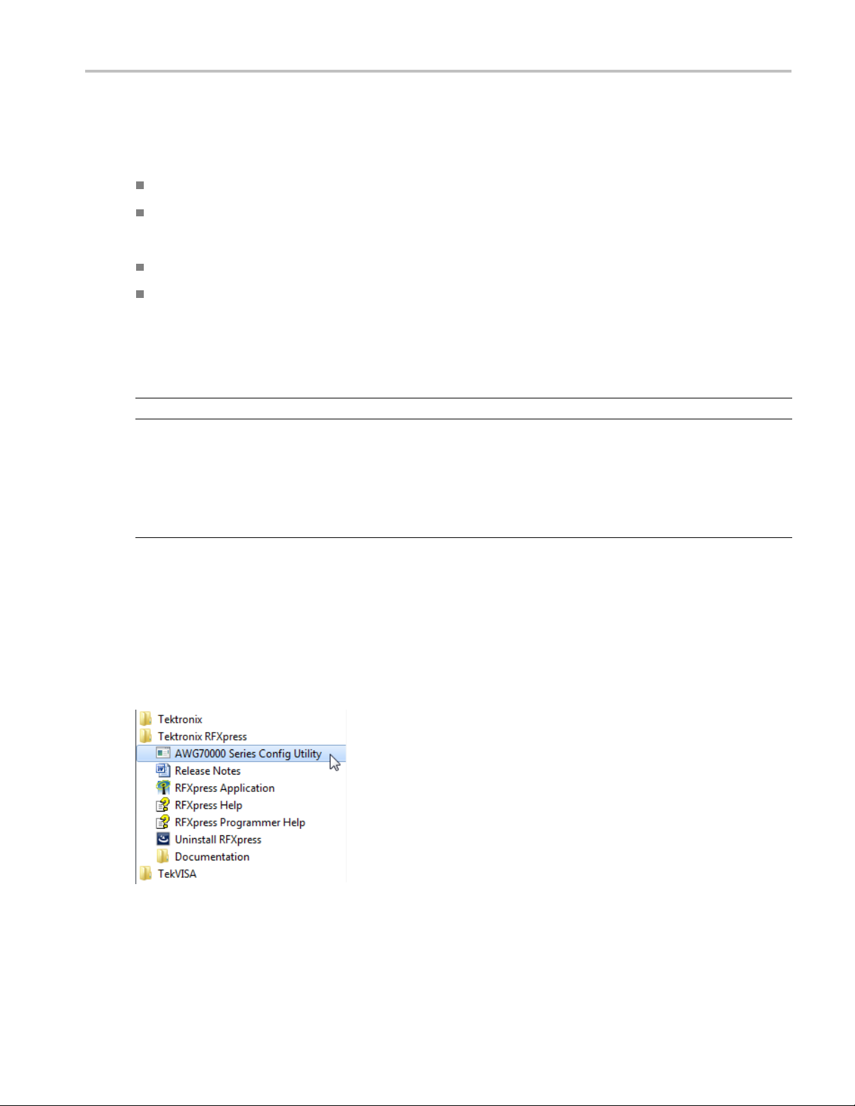
The configuration utility is located in the Tektronix RFXpress Program folder.
When the configuration utility starts, simply enter your AWG70000 Series model number and its options. This information
provides RFXpress with the information to properly adjust variables (such as sampling rate and waveform length) to
accommodate the features of the AWG70000 Series generators.
n
RFXpress RFX100 Quick Start User Manual 1
Page 16

Installation
NOTE. All instrument information entered here must match your AWG70000 Series instrument exactly, including all options.
Any mismatch of
information will cause a an error when attempting to connect to the instrument.
Starting the Software
Start the software in either of the following ways:
From Start > Program Files > Tektronix
Double-click the RFXpress icon on your desktop.
Closing the Software
Click File > Exit to close the software.
Software Upgrades
Periodic software upgrades may become available. The software is operational only if you have a valid option key for the
specific instrument model and serial number.
To check for upgrades:
1. Go to w ww.tektronix.com/software.
2. Enter the product name (RFXpress).
RFXpress, click RFXpress.
2 RFXpress RFX100 Quick Start User Manual
Page 17
Using the Softwa
re
Using the Soft
The procedures in this section show you how to use the software to create, compile, and graph signals.
ware
Getting Acquainted with the Software
Use the keyboard or mouse to make selections in the software.
Use menus, toolbars, check boxes, and on-screen buttons to control the software functions. Use Microsoft Windows
techniques to navigate menus and select or clear check boxes.
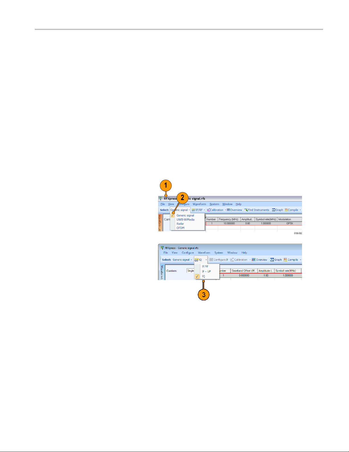
Generatin
g a Single Carrier Signal
This section shows you a step-by-step procedure for creating a single carrier QP SK baseband signal.
1. Start RFXpress.
2. From the toolbar, click Select > Generic
signal.
3. Set the signal type to IQ.
RFXpress RFX100 Quick Start User Manual 3
Page 18

Using the Softwa
4. Click Carriers > Single Carrier.
5. Select the carrier and set the following:
6. Ensure that the following parameters are
set:
re
Baseband Offset to 0 Hz.
Amplitude to 1 Vrms.
Modulation is QPSK.
Filter is Raised Cosine.
Symbol rate is 1 MHz.
Alpha/B*T is 0.35.
Window is None.
Compiling a Signal
Follow these steps to compile and generate a signal using the parameters that you just defined.
1. From the toolbar, click Compile >
Compile Settings.
4 RFXpress RFX100 Quick Start User Manual
Page 19

2. Retain the default values as they are.
Ensure that the Automatic options are
selected.
Using the Softwa
re
3. Click Compile
4. The compiled waveform is displayed in
the waveform list.
.
NOTE. If the waveform list is not visible, click Window > Waveform List to view it.
Generating a Multi-Carrier RF Signal
1. From the toolbar, click Select > Generic
signal.
2. Select the signal type as IF/RF.
RFXpress RFX100 Quick Start User Manual 5
Page 20

Using the Softwa
3. Select Multi Carrier.
re
4. You can either
delete the existing carrier and add new
ones. Select the carrier in the table and
click Delete
5. Click Add ca
6. Click Range
10 M and the Carrier spacing to 10 M.
7. Click Add.
8. Select the first carrier from the table.
In the Setup tab, set the Base data to
PRBS and select 15 from the adjacent
field.
add carriers directly or
.
rriers and type 3.
. Set the Base frequency to
9. Set the Modulation forthecarrierto
QPSK.
10. Repeat steps 8 and 9 for the remaining
carriers, setting the Base data to
S 21 and PRBS 7, and Modulation
PRB
to QPSK.
6 RFXpress RFX100 Quick Start User Manual
Page 21

Adding Power Ramping, I/Q Impairments, and Interference
Using the Softwa
re
1. Select the firs
the table. Select the Power
Ramping tab.
2. Select Turn on.
3. Set the Ramp parameters:
Function to Linear.
Time to 100 ns.
4. Set the Position parameters:
Symbol to 0.
Level to 0.00.
5. Click Add.
6. Repeat steps 4 and 5 two more
times, adding these parameters:
Symbol = 100
Level = –60 dB
and
t carrier from
Symbol
Level =
= 200
0dB
RFXpress RFX100 Quick Start User Manual 7
Page 22

Using the Softwa
7. Select the second carrier
from the table. Select the I/Q
Impairments t
re
ab.
8. In the Carrie
select Turn on . Set the following
parameters:
I to 5.0.
Q to 5.0.
9. Select the third carrier from the
table. Select the Interference
Additi
r Leakage group,
on tab.
10. In the O
ffset group, select Turn
on.SettheFrequency to 10 M.
8 RFXpress RFX100 Quick Start User Manual
Page 23

CompileSettingsandCompile
Using the Softwa
re
1. From the toolb
Compile Settings.
2. Clear Automatic.
3. Set the Waveform length to 500 k and
the units to sa m ples.
4. Clear Automatic.
5. Set the Oversampling to 6.00.
6. Click Compile.
ar, click Compile >
7. The compiled waveform is displayed in
veform list.
the wa
RFXpress RFX100 Quick Start User Manual 9
Page 24
Using the Softwa
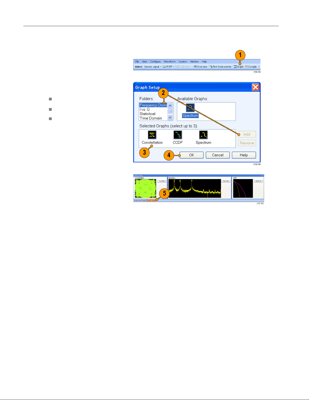
Previewing Graphs
re
1. From the toolb
2. In Graph S etup, select the folder and
click Add to add the following graphs:
Frequency Domain: Spectrum.
I Vs Q: Constellation.
Statistical: CCDF.
3. The graphs are added to the Selected
Graphs.
4. Click OK.
5. Click Graph Preview at the lower left of
the screen to view the graphs.
ar, click Graph.
10 RFXpress RFX100 Quick Start User Manual
Page 25
Replay a Captured Waveform to Test Receivers
You can capture a real-world signal in a real-time spectrum analyzer and play it back in multiple locations to test your DUTs.
Import an RTSA File
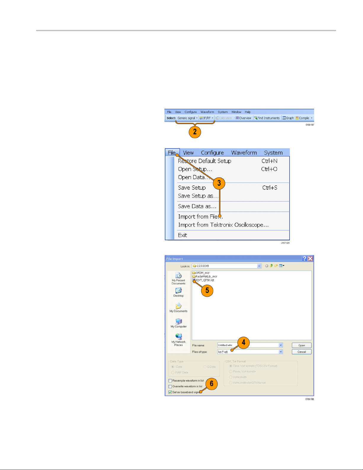
1. Start RFXpress.
2. Ensure that the selected application is
set to Generic signal and the signal type
is IF/RF.
3. From the menu, click File>Importfrom
File.
Using the Softwa
re
4. Select iqt in the Files of type field.
5. Select an iqt file.
6. Select Set as baseband signal.
RFXpress RFX100 Quick Start User Manual 11
Page 26
Using the Softwa
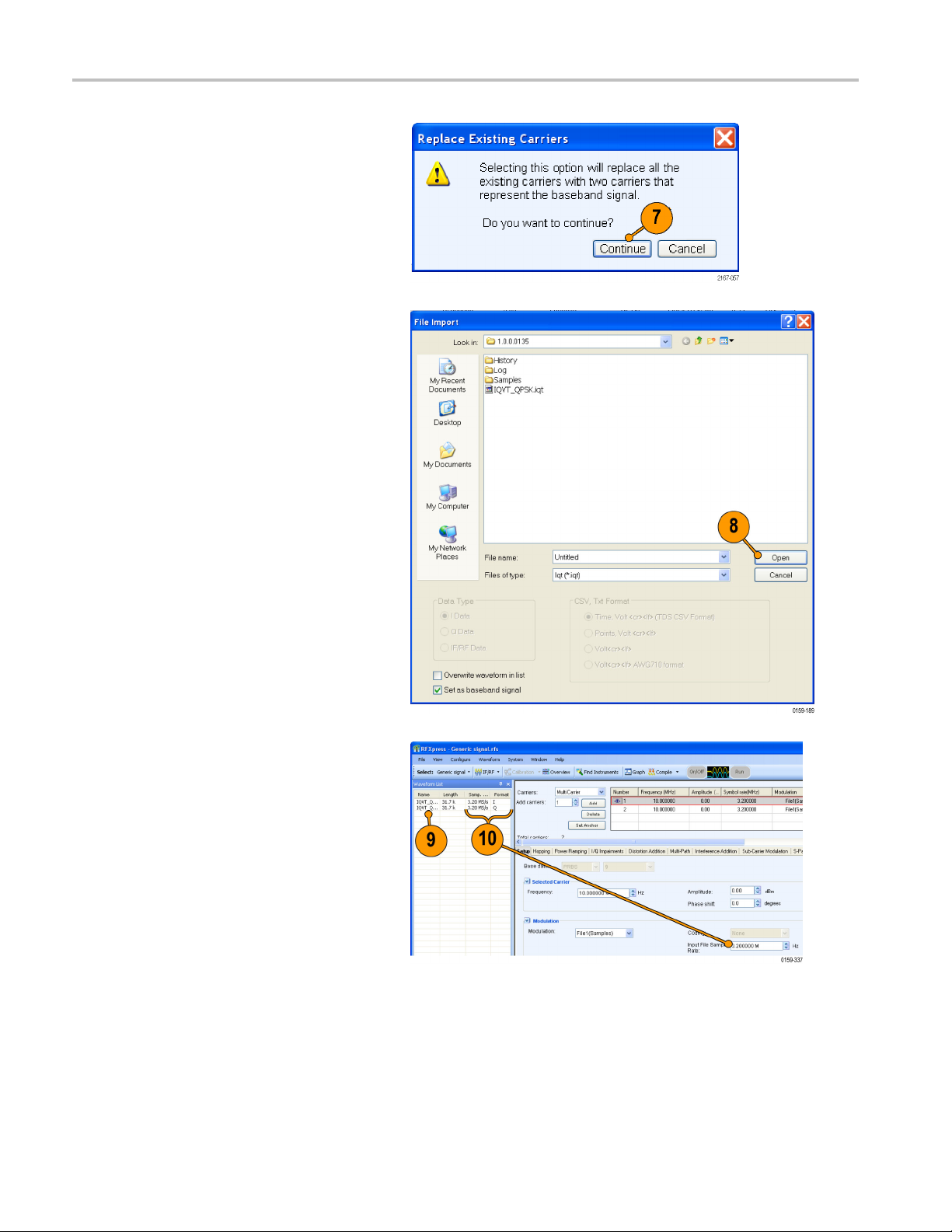
7. A message appears. Click Continue.
8. Click Open.
re
9. The wa
veform list displays the I and Q
signals.
10. O b serve that the Input File Sample
Rate automatically takes the v alue with
htheiqtfile was created.
whic
12 RFXpress RFX100 Quick Start User Manual
Page 27

11. Select the first carrier and set the
following:
Frequency to 50 M.
Amplitude to 0 dBm.
Using the Softwa
re
12. Click Inte
rference Addition.Inthe
Sinusoidal Interference group, select
Turn on.
13. Set the following:
C/I to 0 dB.
Offset from Carrier to –10 M.
14. Select
the second carrier and repeat
steps 11 through 13.
RFXpress RFX100 Quick Start User Manual 13
Page 28
Using the Softwa
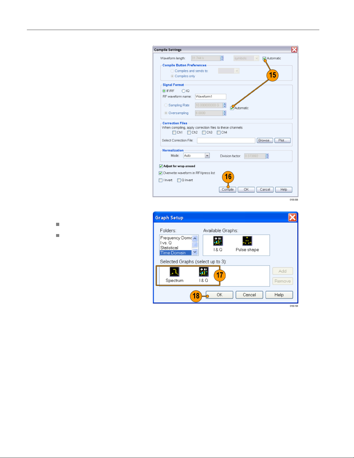
15. Click Compile > Compile Settings.
Ensure that Automatic is selected.
16. Click Compile. The software uses the
default compi
waveform.
re
le settings to generate the
17. Add the following graphs in Graph Setup:
Frequency Domain: Spectrum.
Time Domain: I & Q.
18. Click OK.
14 RFXpress RFX100 Quick Start User Manual
Page 29

19. The Spectrum graph is as shown.
Using the Softwa
re
RFXpress RFX100 Quick Start User Manual 15
Page 30
Using the Softwa
re
Calibrating a Generic RF Signal
When creating signals for testing wideband receivers, it is important that the test equipment generate signals with flat
frequency and linear phase response. As the signal bandwidth is increased, because of the DAC roll-off and bandwidth
limitation of the arbitrary waveform generator, the signal that is created does not have flat frequency and linear phase
response. Calibration (predistortion) is applied to signals to correct amplitude and phase distortions.
1. Set up the instruments as shown. The
instruments must be c onnected over a
LAN.
You will need:
A Tektronix AWG7122C with Option
06, running RFXpress software.
or
A Tektronix AWG70000A Series
instrument with the RFXpress
software running on a PC
connected to the AWG70000A
Series instrument.
A Tektronix DPO oscilloscope to
capture the signal. Ensure that the
oscilloscope is calibrated.
Connecting cable.
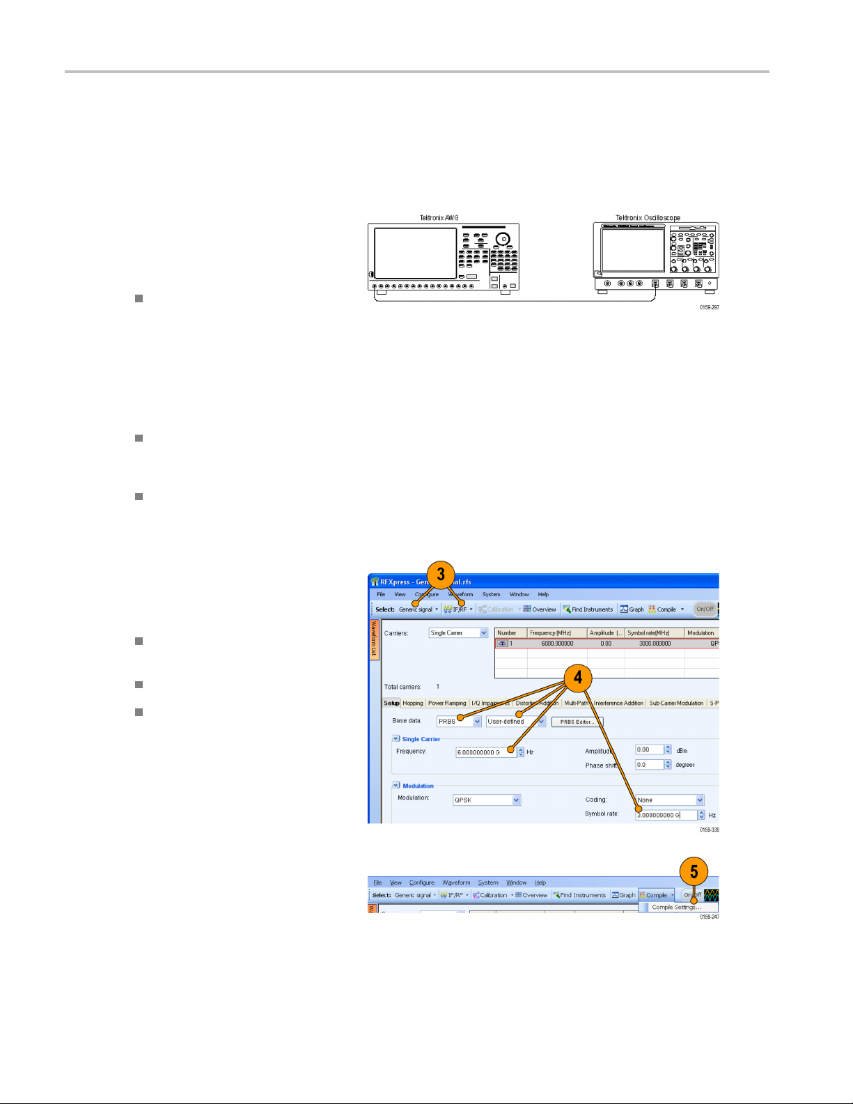
2. Start RFXpress.
3. From the toolbar, click Select > Generic
signal and signal type to IF/RF.
4. For the carrier, set the following:
Base data to PRBS and User
Defined.
Frequency to 6 GHz.
Symbol rate to 3 GHz.
5. From the toolbar, click Compile >
Compile Settings.
16 RFXpress RFX100 Quick Start User Manual
Page 31

Using the Softwa
re
6. Disable Automa
tic and set the
Waveform length to 200 k symbols.
7. Ensure that When compiling, apply
correction files to these channels is
disabled.
8. Click Compil
e.
9. Capture the waveform in the
oscilloscope. The signal spectrum
is observed using Tektronix Ultra
Wideband Spectral Analysis software.
RFXpress RFX100 Quick Start User Manual 17
Page 32

Using the Softwa
10. O b serve that the EVM value before
calibration is 22.99%.
11. From the toolbar, click Calibration.
NOTE. You will be prompted with a message
to compile your setup, if you have not already
done so. Click Continue to proceed with
calibration.
re
12. In the Calibration wizard, set the
following:
Calibration Type to RF.
Calibration using to Oscilloscope.
13. Click Next.
18 RFXpress RFX100 Quick Start User Manual
Page 33

14. The wizard displays a table of
instruments connected on the network.
Select the DPO
Connect. Observe that the status
changes to Connected.
oscilloscope and click
Using the Softwa
re
NOTE. You ca n
the status of the instrum ent.
15. Click Next.
16. Set the following:
Start Frequency to 3.5 GHz.
End Frequency to 8.5 GHz.
Frequency Resolution to 10 M.
Save the correction file to: for a
path and file name to generate and
save the
Select
17. Click N
click Test Connection to test
correction file.
Ch1.
ext.
RFXpress RFX100 Quick Start User Manual 19
Page 34

Using the Softwa
18. S e t the oscilloscope channel to Ch1.
Click Next to start calibration.
re
NOTE. The Illu
stration is a sample when
connected to an AWG7000C series
instrument with Option 06.
When connected to an AWG70000A Series
instrument,
the AWG Channel(s) indicates
Ch1.
19. Once the calibration is complete, click
Next to display the phase and amplitude
plots.
20 RFXpress RFX100 Quick Start User Manual
Page 35

20. Click Finish to exit the wizard.
21. From the toolbar, click Compile.
Using the Softwa
re
RFXpress RFX100 Quick Start User Manual 21
Page 36

Using the Softwa
22. Capture the calibrated waveform in the
oscilloscope. The signal spectrum is
observed usin
Spectral Analysis software.
23. O b serve that the EVM value after
calibration is 8.03%.
re
g Tektronix Ultra Wideband
22 RFXpress RFX100 Quick Start User Manual
Page 37

Calibrating a Generic IQ Signal
When creating signals for testing wideband receivers, it is important that the test equipment generate signals with flat
frequency and linear phase response. As the s ignal bandwidth is increased, because of the DAC roll-off and bandwidth
limitation of the arbitrary waveform generator, the signal that is created does not have flat frequency and linear phase
response. Calibration (predistortion) is applied to signals to correct amplitude and phase distortions.
1. Set up the instruments as shown. The
instruments must be connected over a
LAN.
You will need:
A Tektronix AWG7122C, running
RFXpress software.
or
A two channel TektronixAWG70000A
Series instrument with the
RFXpress sotfware running on
a PC connected to the AWG70000A
Series instrument.
A Tektronix DPO oscilloscope to
capture the signal. Ensure that the
oscilloscope is calibrated.
Using the Softwa
re
Connecting cables.
An IQ modulator to upconvert the
signal to RF.
2. Start RFXpress.
RFXpress RFX100 Quick Start User Manual 23
Page 38

Using the Softwa
3. From the toolbar, click Select > Generic
signal and signal type to IQ.
4. For the carrier, set the following:
re
Base data to PRBS and User
Defined.
Baseband Of
Amplitude t
Modulation
Symbol rat
5. Set the required carrier frequency in the
IQ modulator (for example, 4 GHz).
6. From the toolbar, click Compile >
Compile Settings.
fset to 0 Hz.
o0.25Vrms.
to QPSK.
e to 400 MHz.
24 RFXpress RFX100 Quick Start User Manual
Page 39

7. Retain the default values as they are.
8. Click Compile.
Using the Softwa
re
9. Capture the waveform in the
oscilloscope. The signal spectrum
and EVM are observed using SignalVu
software.
10. Observe that the EVM value before
calibration is 6.393%.
11. From the toolbar, c lick C a libration.
NOTE. You will be prompted with a message
to compile your setup, if you have not already
done so. Click Continue to proceed with
calibration.
RFXpress RFX100 Quick Start User Manual 25
Page 40

Using the Softwa
12. In the Calibration wizard, set the
following:
13. Click Next.
14. The wizard displays a table of
instruments connected on the network.
Select th
Connect. Observe that the status
changes to Connected.
re
Calibration Type to IQ.
Calibration using to Oscilloscope.
e DPO oscilloscope and click
NOTE. Yo
the status of the instrum ent.
15. Click N
u can click Test Connection to test
ext.
26 RFXpress RFX100 Quick Start User Manual
Page 41

16. Set the following:
IChannelto Ch1.
QChannelto Ch2.
Bandwidth to 588 MHz.
Baseband Offset to 0 Hz.
Frequency Resolution to 1 MHz.
Average to 1.
Carrier Frequency to the frequency
set in the IQ modulator (for example,
4GHz).
Using the Softwa
re
Save the co
path and file name to generate and
save the correction file.
17. Click Next.
18. Set the oscilloscope channel to Ch1.
Click Ne
rrection file to: for a
xt to start calibration.
RFXpress RFX100 Quick Start User Manual 27
Page 42

Using the Softwa
19. Once the calibration is complete, click
Next to display the phase and amplitude
plots.
20. Click Finish to exit the wizard.
re
21. From the toolbar, click Compile.
In the compiled waveform, the signal is
distorted with the calibration results.
pre-
28 RFXpress RFX100 Quick Start User Manual
Page 43

22. Capture the calibrated waveform in
the oscilloscope. The signal spectrum
and EVM are obs
software.
23. Observe that the EVM value after
calibration is 2.878%.
erved using SignalVu
Using the Softwa
re
ApplyingCalibrationtoanImportedCustomSignal
In this ex
1. Set up the instruments as shown. The
2. Start RFXpress.
3. From the toolbar, click Select > Generic
ample, you import an OFDM signal (not created using RFXpress) and calibrate it.
instruments must be connected over a
LAN.
You will need:
A Tektronix AWG7122C with Option
06, running RFXpress software.
or
A Tektronix AWG70000A Series
instrument with the RFXpress
are running on a PC
softw
connected to the AWG70000A
Series instrument.
A Tektronix DPO oscilloscope to
ure the signal. Ensure that the
capt
oscilloscope is calibrated.
Connecting cable.
signal and set the signal type to IF/RF.
RFXpress RFX100 Quick Start User Manual 29
Page 44

Using the Softwa
4. Select File > Import from File.
5. Select a file, for example RefSig.mat.
Set the Data Type to IF/RF Data and
click Open. RefSig.mat represents an
OFDM signal that cannot be directly
generated using RFXpress.
re
NOTE. If you import a .txt file, you are
prompted to enter the sampling rate.
30 RFXpress RFX100 Quick Start User Manual
Page 45

6. Select the signal and right-click. Select
SendtoAWG>Ch1.
Using the Softwa
re
NOTE. For AWG7
ensure that the output of the AWG Interleave
channel is connected to Channel 1 of the
oscilloscop
7. Capture the waveform on the
oscilloscope and observe the signal
spectrum
Spectral Analysis software. Note that the
frequency response is not flat.
000C Series instruments,
e.
using Tektronix Ultra Wideband
8. From th
9. Ensure that the signal type is RF and
e toolbar in RFXpress, click
Calibration. The calibration wizard
opens.
click Next.
RFXpress RFX100 Quick Start User Manual 31
Page 46

Using the Softwa
10. From the table of instruments connected
on the network, select a Tektronix
oscilloscope
Observe that the status changes to
Connected. Click Next.
re
and click Connect.
NOTE. Yo u ca n
the status of the instrum ent.
11. Set the following:
Start Frequency to 3.5 GHz.
End Frequency to 6.5 GHz.
NOTE. The start and end frequencies
ond to the bandwidth of the imported
corresp
OFDM signal.
Save the correction file to: for a
path an
save the correction file.
Select Ch1.
click Test Connection to test
d file name to generate and
12. Click Next.
13. Once the calibration is complete, click
Next to display the amplitude and phase
s. Click Finish to exit the wizard.
plot
32 RFXpress RFX100 Quick Start User Manual
Page 47

14. In the waveform list, select the signal and
right-click. Select Apply Calibration.
15. Select the correction file that was created
during calibration and click Open.
The correction file is applied to the
existing imported signal.
Using the Softwa
re
RFXpress RFX100 Quick Start User Manual 33
Page 48

Using the Softwa
16. To see the calibrated signal in the AWG,
select the file, right-click, and choose
Send to AWG > Ch
17. Capture the waveform on the
oscilloscope and observe the signal
spectrum
Spectral Analysis software. Note that the
frequency response is flat.
re
1.
using Tektronix Ultra Wideband
34 RFXpress RFX100 Quick Start User Manual
Page 49

Characterizing a Low-pass Wideband Filter (DUT)
You can determine the characteristics of a device under test, a low-pass wideband filter in this case, and store these
characteristics in a file. Use this file later as an input to the S-parameter feature.
1. Set up the instruments as shown. The
instruments must be connected over a
LAN.
You will need:
A Tektronix AWG7122C with Option
06, running RFXpress software.
or
A Tektronix AWG70000A Series
instrument with the RFXpress
software running on a PC
connected to the AWG70000A
Series instrument.
A Tektronix DPO72004 oscilloscope
to capture the signal. Ensure that the
oscilloscope is calibrated.
Connecting cable.
Using the Softwa
re
A low-pass wideband filter (the device
under test)
NOTE. For AWG7000C Series instruments,
ensure that the output of the AWG Interleave
channel is connected to Channel 1 of the
oscilloscope.
2. Start RFXpress.
Select DUT characterization from the
toolbar.
RFXpress RFX100 Quick Start User Manual 35
Page 50

Using the Softwa
3. The DUT Characterization wizard opens.
Click Next.
4. Select an oscilloscope from the list and
click Connect.
re
NOTE. If y
ou are unable to view a list of
connected instruments, click Refresh List.
5. Click Next.
6. Set the following Setup parameters:
Sampling Rate to 24 GS/s.
For AWG7000C Series instruments,
enable Interleave.
Select Ch1.
DAC Res to 8 bits.
36 RFXpress RFX100 Quick Start User Manual
Page 51

7. Set the other parameters as follows:
Start Frequency to 10 MHz.
End Frequency to 11.76 MHz.
Frequency Resolution to 10 MHz.
Average to 1 iteration.
8. Click Next.
9. Select the oscilloscope channel Ch1 to
connect the AWG channel to.
Using the Softwa
re
10. Click Next to start AWG calibration.
NOTE. AWG calibration may take up to
minutes.
10-15
11. Once calibration is over, click Next.
RFXpress RFX100 Quick Start User Manual 37
Page 52

Using the Softwa
12. A dd the low-pass wideband filter at
channel 1 of the oscilloscope.
13. Specify the output file name. Click Next.
re
NOTE. Charac
to 10-15 minutes.
14. Click Next.
terizing the DUT may take up
38 RFXpress RFX100 Quick Start User Manual
Page 53

15. Click Next.
The wizard displays phase and amplitude
plots.
16. Click Finish to exit the wizard.
Use the file with the DUT characteristics as
an input t
o S-parameter function.
Using the Softwa
re
RFXpress RFX100 Quick Start User Manual 39
Page 54

Using the Softwa
re
Creating a UWB Waveform to Test Your Receivers
You can create an ideal waveform and use it to test whether your receivers are operating within the WiMedia specifications.
1. Start RFXpress.
2. From the toolbar, click Select >
UWB-WiMedia.
3. By default, Conformance is selected.
4. From the Select Setup, select WiMedia
Spec Example Packet.
5. The WiMed
settings (according to Annex A of the
WiMedia specification document) are
display
6. Confirm t
Code 1.
7. Click Compile.
ia Spec Example Packet
ed in the fields in each tab.
he Hopping Pattern for TF
40 RFXpress RFX100 Quick Start User Manual
Page 55

8. Add the following graphs in Graph Setup:
Frequency Domain: Spectrum.
I Vs Q: Constellation.
Time Domain: I & Q.
9. Click OK.
10. The graphs are as shown.
Using the Softwa
re
RFXpress RFX100 Quick Start User Manual 41
Page 56

Application Exa
mples: Generic Signal
Application E
xamples: Generic Signal
Simulating a Multi-Path Environment for a Generic Signal
You can simulate multi-path to test your receiver's response to multi-paths.
1. Start RFXpress.
2. From the toolbar, ensure that Select >
Generic signal is selected.
3. Ensure that the signal type is set to
IF/RF.
4. Ensure that Single Carrier is selected.
Leave the default values for the carrier.
5. Click Multi-Path and select Turn on.
6. Set the following parameters:
Delay to 4 symbols.
Amplitude to –1 dB.
Phase to 30 degrees.
7. Click Add.
8. Repeat steps 6 and 7, setting the
following parameters:
Delay to 10 symbols.
Amplitude to –5 dB.
Phase to 60 degrees.
42 RFXpress RFX100 Quick Start User Manual
Page 57

9. In Graph Setup, add the following graph:
Time Domain: Pulse shape.
10. Click OK.
11. From the toolbar, click Compile.
12. The pulse shape is as shown.
Application Exa
mples: Generic Signal
RFXpress RFX100 Quick Start User Manual 43
Page 58

Application Exa
mples: Generic Signal
Creating a Hopping Waveform to Test Radio Signal Identification and Detection
Systems
A radio signal identification and detection receiver is assigned to gather information about all transmissions in the radio
band. The specific tasks of a receiver include the ability to detect and analyze the received transmission, estimate frequency
and modulation type, extract intelligence (information), and locate the source. This example addresses the challenges in
generating a wide range of real-world signals and hopping signals required to test these receivers.
1. Start RFXpress.
2. From the toolbar, click Select > Generic
signal.
3. Ensure that the signal type is set to
IF/RF.
4. Select Carrier to Multi-Carrier.
5. Select the carrier in the table and click
Delete.
6. In Add carriers, enter 6 and click Add.
7. Select the carriers one after another,
starting with the first carrier.
8. Enter the values for each carrier as in
Table 1. (See page 47.)
44 RFXpress RFX100 Quick Start User Manual
Page 59

9. Select the sixth carrier and click Set
Anchor.
10. Click the Hopping tab and select Turn
on.
11. Ensure that the Hop Frequency Pattern
is set to Cus
tom Table and Enter values
as is set to Frequency Offset.
12. Set the Hop Time Method to Symbol
Index, each Hop.
13. Update the values as shown in Table 2
for each carrier: (See page 47.)
Application Exa
mples: Generic Signal
14. From the toolbar, click Compile >
Compile Settings.
RFXpress RFX100 Quick Start User Manual 45
Page 60

Application Exa
15. Disable Automatic and set Waveform
16. Click Compile.
mples: Generic Signal
length to 384 symbols.
17. From the waveform list, select an IF/RF
waveform. Right-click and select Show
Graph > Spectrogram.
46 RFXpress RFX100 Quick Start User Manual
Page 61

Application Exa
mples: Generic Signal
18. The spectrogra
m is as shown.
Table 1: Carrier parameters
Carrier
Signal
number
131–6
2790
3 237 4 FM 30 KHz
4 432 10
5
6 673 0.5
frequency
(MHz)
131 1
Amplitude
(dBm) Modulation
QPSK
8-PSK
64-QAM
Pi 1/4 QPSK
BPSK
Symbol rate
(MHz) Filter Window
0.5
2 Root Raised
1
5
2
RC
Cosine
-
Gaussian
(Dirac Delta)
RC
RC
Blackman
Hamming
None
Hamming
Blackman
None
Table 2: Hopping parameters
Relative amplitude
Signal number Start symbol End symbol
1 1 127 0 –25
2 128 255 0 0
3 256 384 0 –50
(dB)
Frequency offset
(MHz)
RFXpress RFX100 Quick Start User Manual 47
Page 62

Application Exa
mples: Generic Signal
S-Parameter Emulation of a High Pass Filter
This example emulates the high pass filter on multitones from 50 MHz to 9.95 GHz and applies the high-pass filter
S-parameter characteristics on a calibrated multitone signal. To c alibrate a signal, see the calibration procedure. (See
page 23, Calibrating a Generic IQ Signal.)
1. Start RFXpress.
2. From the toolbar, click Select > Generic
signal.
3. Ensure that the signal type is set to
IF/RF.
4. Set Carriers to Multi Carrier.
5. Select the carrier and click Delete.
6. In Add c
Enter.
7. Click Range.
arriers, type 199 and press
48 RFXpress RFX100 Quick Start User Manual
Page 63

8. Set the following:
Base frequency to 50 M.
Carrier spacing to 50 M.
9. Click Add.
10. From the toolbar, click Compile
Settings.
11. Select the correction file (created during
on), and click Compile.
calibrati
To create the correction file, refer to the
calibration procedure. (See page 23,
ing a Generic IQ Signal.)
Calibrat
Application Exa
mples: Generic Signal
12. Capture the waveform in the
oscilloscope. The signal spectrum
is observed using Tektronix Ultra
Wideband Spectral Analysis software.
RFXpress RFX100 Quick Start User Manual 49
Page 64

Application Exa
13. Click the S-Parameters tab and select
14. B rowse the Touchstone file to emulate.
15. Select Full Bandwidth.
16. From the toolbar, click Compile.
NOTE. In the message box, click Continue
to proceed
17. O b serve the signal spectrum using
mples: Generic Signal
Turn On.
This example
high-pass filter with a cut-off of 5.5 GHz.
Tekt r oni
Analysis software.
uses a .s2p file for a
.
x Ultra Wideband Spectral
18. To verify the spectrum and the
meter, connect a high-pass filter
S-para
(DUT) as shown.
ktheS-Parameters tab and select
19. Clic
Turn On (toturnitoff).
50 RFXpress RFX100 Quick Start User Manual
Page 65

20. From the toolbar, click Compile.
21. Observe the signal spectrum using
Tektronix Ultra Wideband Spectral
Analysis software.
Application Exa
mples: Generic Signal
RFXpress RFX100 Quick Start User Manual 51
Page 66

Application Exa
mples: UWB-WiMedia
Application Examples: UWB-WiMedia
Characterize Receiver Design for R eceiver Verification and Stress Test
You can generate a signal and use it to test your receiver at conditions just outside the boundary values specified by the
WiMedia standard.
1. Start RFXpress.
2. From the toolbar, click Select >
UWB-WiMedia.
3. Set the signal type to IF/RF.
4. Select Custom.
5. From the Select Setup, select WiMedia
Spec Example Packet.
6. The default values for the selected setup
and packet are shown graphically.
7. For the selected packet group, set TF
Code to User Defined.
8. To define a hopping pattern: In each
column, click the frequency that you
want to use. Set the hopping pattern to:
323323.
9. Assign a TFC number for the pattern that
you defined and click OK.
52 RFXpress RFX100 Quick Start User Manual
Page 67

Adding Interference
Application Exa
mples: UWB-WiMedia
1. Click Interfe
2. In the Gated No
on.
3. Click Packets.
4. Click PLCP Header and set it to –10.0.
5. From the toolbar, click Compile.
6. In the Wave
waveform and right-click. Select Show
Graph > Time domain.
rence Addition.
ise group, select Turn
form List, select the IF/RF
7. Observe the noise in the header. The
f 10 dB is greater than the signal.
noise o
RFXpress RFX100 Quick Start User Manual 53
Page 68

Application Exa
mples: UWB-WiMedia
Using Calibration to Increase the Flatness of a UWB Signal Path to the DUT
The calibration feature allows you to generate correction files that you can use during compilation to predistort the signal,
thereby increasing the flatness of the signal.
1. Set up the instruments as shown. The
instruments must be c onnected over a
LAN.
You will need:
A Tektronix AWG7122C with Option
06, running RFXpress software.
or
A Tektronix AWG70000A Series
instrument with the RFXpress
software running on a PC
connected to the AWG70000A
Series instrument.
A Tektronix DPO70804 oscilloscope
to capture the signal. Ensure that the
oscilloscope is calibrated.
Connecting cable.
NOTE. For AWG7000C Series instruments,
ensure that the output of the AWG Interleave
channel is connected to Channel 1 of the
oscilloscope.
2. Start RFXpress.
3. From the toolbar, click Select >
UWB-WiMedia.
4. From the toolbar, click Calibration.
54 RFXpress RFX100 Quick Start User Manual
Page 69

5. The Calibration window displays a table
of instruments connected on the network.
Select the DPO
click Connect. Observe that the status
changes to Connected.
70804 oscilloscope and
Application Exa
mples: UWB-WiMedia
NOTE. You ca n
the status of the instrum ent.
6. Set the sign
7. Set the Samp
19.996576 GS/s.
8. For AWG7000C Series instruments,
select InterLeave.
9. Set the Average to 10.
10. Set the Band group to 2.
11. Select Bands: 1, 2, and 3.
12. Set While compiling, apply correction
files to to Ch1.
13. Set the Amplitude for Ch 1 to 0.5 Vpp.
14. Set the path for Select the correction
file.
15. Click C
file (.rfc). The calibration status is
continually updated.
click Test Connection to test
al type to RF.
ling rate to
alibrate to create the correction
16. Confirm that the correction file that was
nerated is selected.
just ge
RFXpress RFX100 Quick Start User Manual 55
Page 70

Application Exa
17. Set Band Group to Band Group 2.
18. From the toolbar, click Compile >
mples: UWB-WiMedia
Compile Settings.
19. Ensure that the correction file created
during calibration is applied to Ch1.
NOTE. Oversampling is calculated
automatically to achieve a sampling rate of
19.996576 GS/s.
20. Click Compile.
56 RFXpress RFX100 Quick Start User Manual
Page 71

Introducing Real-World Impairments in a UWB Signal
You can introduce real-world impairments in a UWB signal to test your receiver in a simulated real-world environment.
1. Start RFXpress.
2. From the toolbar, click Select >
UWB-WiMedia.
3. Ensure that the signal type is set to
IF/RF.
4. Ensure that the Mo de is Conformance
and the Selected setup is WiMedia
Spec Example Packet. Leave the default
values for the selected setup.
Application Exa
mples: UWB-WiMedia
5. Click Int
6. In the Re
group box, click Turn on.
7. Click Add WiFi signal (MIMO).
8. Set the following parameters:
erference Addition.
al World Signal Interference
Frequency to 2.4 GHz (default).
Amplitude to 30 dB.
RFXpress RFX100 Quick Start User Manual 57
Page 72

Application Exa
9. In Graph Setup, add the following graph:
10. Click OK.
11. From the toolbar, click Compile.
12. The spectrum is as shown.
mples: UWB-WiMedia
Frequency Domain: Spectrum
58 RFXpress RFX100 Quick Start User Manual
Page 73

Application Exa
mples: Radar
Application Examples: Radar
Generating an LFM Waveform with Coherent Carrier for Pulse Compression
Radar
Use the Radar plug-in to generate an LFM waveform with coherent carrier for pulse compression radar.
1. Start RFXpress.
2. From the toolbar, click Select > Radar.
3. Click the Carrier tab.
4. Keep the following defaults:
Carrier Magnitude (Peak) to 0 dBm.
Carrier Frequency to 100 MHz.
Coherent Carrier is selected.
RFXpress RFX100 Quick Start User Manual 59
Page 74

Application Exa
5. Select the Pulse tab and select the
6. Set the following:
mples: Radar
Pulse Envelope tab.
Pulse Shape to Rectangular
(default).
Start Time t
Pulse Width
Off Time to 1
NOTE. The PRF and PRI values are
calculated and automatically updated based
on the para
case, the PRF is 4.807 KHz and the PRI (in
the table) is 0.2080 ms.
Amplitud
0 dB (default).
Offset from Carrier Frequency to
0 Hz (default).
Repeat to 1 (default).
7. Click the Modulation tab.
8. Set the following:
Select Modulation to Linear
Frequ
Swee
o 0 ps (default).
to 10 µs at 100%.
98 µs.
meters that you just set. In this
e Relative to Carrier to
ency Modulation.
pRangeto 10 MHz.
uency Sweep to Low to High.
Freq
9. From the toolbar, click Compile
Settings.
60 RFXpress RFX100 Quick Start User Manual
Page 75

10. Ensure the following:
Signal Format is IF/RF.
Automatic is selected.
11. Click Compile.
Application Exa
mples: Radar
12. The compiled pulse is displayed in the
Waveform List. In the Waveform List,
select the I signal and right-click. Select
Show Graph > Time domain to display
the graph of the pulse.
13. Click Zoom In and select an area to
zoom.
RFXpress RFX100 Quick Start User Manual 61
Page 76

Application Exa
mples: Radar
Generating a Hopping Radar Waveform: Creating a Pulse-to-Pulse Frequency
Hopping Signal
Pulse-to-pulse hopping radar signals are also known as frequency agile waveforms. Pulse-to-pulse hopping is used in
electronic counter measures by rapidly switching the frequency of the transmitted energy and receiving only that frequency
during the receiving time window.
1. Start RFXpress.
2. From the toolbar, click Select > Radar.
3. In the Carrier tab, ensure that Coherent
Carrier is selected (default).
4. Carrier Frequency to 200 MHz.
62 RFXpress RFX100 Quick Start User Manual
Page 77

5. Select the Pulse tab and select the
Pulse Envelope tab.
6. Set the following:
Pulse Shape to Raised Cosine.
Start Time to 0 ps (default).
Rise Time to 0.1 µs at 20–80%.
Pulse Width to 15 µs at 50%.
Fall Time to 0.1 µs at 20–80%.
Off Time to 30 µs.
Application Exa
mples: Radar
NOTE. The P
calculated and automatically updated based
on the parameters that you just set. In this
case, the P
the table) is 0.0452 ms.
7. Click the Modulation tab and set Select
Modulation to No Modulation.
RF and PRI values are
RF is 22.102 KHz and the PRI (in
Amplitude Relative to Carrier to
0 dB (def
Offset f
0 Hz (default).
Repeat to 6.
ault).
rom Carrier Frequen c y to
RFXpress RFX100 Quick Start User Manual 63
Page 78

Application Exa
8. Click the Hopping tab and select Turn
9. Set the Pattern to Custom Table, then
NOTE. You cannot add more rows than the
repeat value (6 in this case).
10. Set the following:
mples: Radar
on.
click Add to ad
Frequency Offset for the first hop to
50 MHz.
Frequency Offset for the second hop
to 40 MHz.
drows.
Frequency Offset for the third hop to
–50 MHz.
Frequency Offset for the fourth hop
to 0 MHz.
Frequency Offset for the fifth hop to
30 MHz.
Frequency Offset for the sixth hop to
–30 MHz.
11. From the toolbar, click Compile
Settings.
64 RFXpress RFX100 Quick Start User Manual
Page 79

12. Ensure the following:
Signal Format is IF/RF.
Automatic is selected.
13. Click Compile.
NOTE. The Compile Settings display is
dependent on
the type of AWG connection
and may appear different.
Application Exa
mples: Radar
14. The compi
led pulse is displayed in the
Waveform List. In the Waveform List,
select the IF/RF signal and right-click.
Select S
how Graph > Spectrogram to
display the graph of the pulse.
RFXpress RFX100 Quick Start User Manual 65
Page 80

Application Exa
mples: Radar
15. The spectrogra
m is as shown.
NOTE. For better resolution, increase the
frame size and click Refresh.
16. The spectrogram as seen in a Tektronix
RSA6100A is as shown.
66 RFXpress RFX100 Quick Start User Manual
Page 81

Creating Costa’s Modulation
Use RFXpress to test receivers with Costa’s modulation, which are used for better range and Doppler resolution.
1. Start RFXpress.
2. From the toolbar, click Select > Radar.
3. Click the Carrier tab.
4. Leave the defaults for Coherent Carrier
(enabled) and Carrier Magnitude
(Peak).
5. Set the desired Carrier Frequency,for
example to 1 GHz.
Application Exa
mples: Radar
6. Select the Pulse tab and select the
Pulse En
7. Set the f
velope tab.
ollowing:
hape to Rectangular.
Pulse S
Pulse W
Off Tim
idth to 112 µs.
e to 100 µs.
RFXpress RFX100 Quick Start User Manual 67
Page 82

Application Exa
8. Click the Modulation tab and set Select
mples: Radar
Modulation to User Defined Step FM
AM.
You will create a Costa’s code of seven
steps with Δf = 42.4 MHz. The code that
will be used i
s 3605412.
9. In Add Steps e
10. Click Add.
11. In the table
Duration to
Frequency
12. Repeat ste
the code. Keep the duration constant
(16000 ns) and calculate the frequency
using the
42.4 * 3, 42.4 * 6, 42.4 * 0, and the rest).
13. From the
nter 7.
, enter the following:
16000 ns.
to 127.2 MHz.
p 11 for all the steps in
formula Δf * code (for example
toolbar, click Compile.
68 RFXpress RFX100 Quick Start User Manual
Page 83

14. In the waveform list, select IF/RF.
Right-click and select Show Graph >
Spectrogram.
15. The spectrogram is as shown.
Application Exa
mples: Radar
RFXpress RFX100 Quick Start User Manual 69
Page 84

Application Exa
mples: Radar
Creating a Radar Waveform using Staggered PRI for Better Range Ambiguity
One of the applications of Staggered PRI is in Moving Target Indication (MTI) Radars which have to resolve range and
Doppler ambiguities. This example shows how to create pulse-to-pulse staggering.
1. Start RFXpress.
2. From the toolbar, click Select > Radar.
Select the signal type as IF/RF.
3. Click the Carrier tab.
4. Leave the defaults for Coherent Carrier
(enabled) and Carrier Magnitude
(Peak).
5. Set the Carrier Frequency to 1 GHz.
6. Select the Pulse tab and select the
Pulse Envelope tab.
7. Set the following:
Pulse Shape to Rectangular.
Pulse Width to 11.2 µs.
Off Time to 100 µs.
Repeat to 5.
70 RFXpress RFX100 Quick Start User Manual
Page 85

8. Click the Staggered PRI tab and select
Turn on.
9. Set StaggeredPRI type to User Defined.
You will chan
adding a deviation. The PRI is calculated
as follows: Current PRI + deviation. The
deviation i
ge the PRI for each pulse by
s specified in the table.
Application Exa
mples: Radar
10. Click Add to
11. Enter the de
pulse.
12. Repeat steps 10 and 11 to enter the
deviation for the remaining pulses as:
0.1, –0.05
13. From the to
14. On the RSA, do the following:
Set the center frequency to 1 GHz.
Setthescaleto1ms.
Observe the signal on the RSA.
add a row to the table.
viation 0 (in ms) for the first
, 0.085, 0.13.
olbar, click Compile.
RFXpress RFX100 Quick Start User Manual 71
Page 86

Application Exa
mples: Radar
Simulating Multiple Targets for Radar Receiver Testing (Different Pulse
Groups)
Use RFXpress to simulate three targets. With the transmitter s ending a pulse of duration 5 µs with a PRI of 500 µs, this
example will simulate three targets – the first at 40 µs from the reference, the second at 120 µs, and the third at 300 µs.
1. Start RFXpress.
2. From the toolbar, click Select > Radar.
Set the signal type to IF/RF.
3. Click the Carrier tab.
4. Leave the defaults for Coherent Carrier
(enabled) and Carrier Magnitude
(Peak).
5. Set the Carrier Frequency to 1 GHz.
6. Select the Pulse tab and select the
Pulse Envelope tab.
7. Set the following:
Pulse Shape to Rectangular.
Start Time to 40 µs.
Pulse Width to 5 µs at 100%.
Off Time to 455 µs.
Amplitude Relative to Carrier to
0 dB (default).
Observe that the PRI is 500 µs.
72 RFXpress RFX100 Quick Start User Manual
Page 87

8. Click the Modulation tab and set
Select Modulation to Linear Frequency
Modulation.
Application Exa
mples: Radar
9. Set the follo
Sweep Range t
Frequency S
10. Click Add to add a pulse. Select the
newly added pulse.
11. Select the Pulse Envelope tab.
12. Select the pulse and set the following:
Pulse Shape to Rectangular.
wing:
o10MHz.
weep to Low to High.
Start Time to 120 µs.
Pulse Width to 5 µs at 100%.
Off Time to 375 µs.
Amplitude Relative to Carrier to
.
–2 dB
RFXpress RFX100 Quick Start User Manual 73
Page 88

Application Exa
13. Click the Modulation tab and set
mples: Radar
Select Modulation to Linear Frequency
Modulation.
14. Set the follow
Sweep Range t
Frequency Sw
15. Click Add
16. Select t
17. Select t
to add a pulse.
he Pulse Envelope tab.
he pulse and set the following:
hape to Rectangular.
Pulse S
ime to 300 µs.
Start T
ing:
o10MHz.
eep to Low to High.
Pulse W
Off Ti
Ampli
–3 dB.
idth to 5 µs at 100%.
me to 195 µs.
tude Relative to Carrier to
74 RFXpress RFX100 Quick Start User Manual
Page 89

18. Click the Modulation tab and set
Select Modulation to Linear Frequency
Modulation.
Application Exa
mples: Radar
19. Set the follo
wing:
Sweep Range t
Frequency S
20. Click Add Pu
lse Groups.
21. Click Check All.
22. Click OK.
o10MHz.
weep to Low to High.
m the toolbar, click Compile.
23. Fro
RFXpress RFX100 Quick Start User Manual 75
Page 90

Application Exa
24. Select an IF/RF waveform from the
25. The time domain graphs are as shown.
mples: Radar
waveform list. Right-click and select
Show Graph > Ti
me domain.
Simulating a Scanning Antenna with a Gaussian Shape
RFXpress can be use to simulate different types of beam patterns like Sinc, G aussian, or User-defined scan patterns. In this
example, you will simulate a Gaussian Beam pattern for a stationary target with Maximum Radial Axis (MRA) at 0 degrees.
1. Start RFXpress.
2. From the toolbar, click Select > Radar.
Select the signal type as IF/RF.
3. Click the Carrier tab.
4. Leave the defaults for Coherent Carrier
(enabled) and Carrier Magnitude
(Peak).
5. Set the Carrier Frequency to 3 GHz.
76 RFXpress RFX100 Quick Start User Manual
Page 91

6. Select the Pulse tab and select the
Pulse Envelope tab.
7. Set the following:
Pulse Shape to Rectangular.
Pulse Width to 5 µs.
Off Time to 50 µs.
Repeat to 20.
8. Click the Antenna tab and click Turn On.
9. Set the following:
Beam Type to Gaussian.
Beam Width to 0.05 degree.
Application Exa
mples: Radar
10. From the toolbar, click Compile.
11. Capture the waveform on the
oscilloscope and observe the signal
trum using Tektronix Ultra Wideband
spec
Spectral Analysis software.
RFXpress RFX100 Quick Start User Manual 77
Page 92

Application Exa
mples: OFDM
Application E
xamples: OFDM
Create a TG3c Standard OFDM Symbol
This example creates a 512-subcarrier OFDM symbol according to the timing and subcarrier frequency allocation in the
TG3c draft specification (refer to the timing and frequency allocation tables).
1. Start RFXpress.
2. From the toolbar, click Select > OFDM .
3. Click the Basic Setup tab.
4. Set the Frequency to5GHz.
5. Select Base Data 1 from the list.
6. Set the Data Source to PRBS and
PRBS Type to User Defined.
7. Select Base Data 2 from the list and
enter the Name as Pilot 1.
8. Set the Data Source to Pattern and
Pattern Data to 11.
9. Select Base Data 3 from the list and
enter the Name as Pilot 2.
10. Set the Data Source to Pattern and
Pattern Data to 10.
78 RFXpress RFX100 Quick Start User Manual
Page 93

11. Select Base Data 4.
12. Set the Data Source to PRBS and
PRBS Type to 9.
13. Click the Symbols tab.
14. Set Spacing between Carriers to
5.0625 M.
15. In Add new subcarriers, enter 510 and
click Add.
NOTE. The total number of subcarriers in
the list is 512.
Application Exa
mples: OFDM
RFXpress RFX100 Quick Start User Manual 79
Page 94

Application Exa
16. Set Type to Null.
mples: OFDM
17. Enter the subc
arriers: –256 – –186, 186
– 255.
NOTE. Separate the range with a dash (-)
and the range
18. Click Apply
s with a comma.
.
19. E nter –1, 0, 1 in the field and click Apply
to set the DC subcarriers to Null.
80 RFXpress RFX100 Quick Start User Manual
Page 95

20. Set Type to Pilot.
21. Keep the Modulation as QPSK and set
the Base Data to Pilot 1.
22. Enter the subcarriers:–166, –100, –56,
–12, 34, 122, 166.
23. Click Apply.
Application Exa
mples: OFDM
24. Set Type to Pilot.
25. Keep the Modulation as QPSK and set
the Base Data to Pilot 2.
26. Enter the subcarriers: –144, –122, –78,
–34, 12, 56, 78, 100, 144.
27. Click Apply.
RFXpress RFX100 Quick Start User Manual 81
Page 96

Application Exa
28. Set Type to Guard.
29. Set the Modulation to BPSK and set the
30. Enter the subcarriers: –185 – –178, 178
31. Click Apply.
mples: OFDM
Base Data to Base Data 4.
– 185.
32. Select Cyclic Pre fix.
33. Select Percent and enter 12.5.
This works out to 24.69 ns when cyclic
s specified in time.
prefixi
82 RFXpress RFX100 Quick Start User Manual
Page 97

34. Click the Frames tab.
35. Set Spacing between Packets to
100 μs.
36. Click Compile.
37. Observe the Spectrum graph.
Application Exa
mples: OFDM
Create
RFXpress RFX100 Quick Start User Manual 83
a WiFi Signal using a Preset and Adding Impairments
Use this example to create a WiFi signal using the provided preset file and add clipping, gated noise, and phase noise
to the signal.
1. Start RFXpress.
2. From the toolbar, click Select > OFDM.
3. From the menu, select Presets > WiFi >
802.11a 36 Mbit/s QAM16
Page 98

Application Exa
4. Click the Symbols tab.
5. In the Symbol List, select Payload1.
6. Enable Clipping Ratio and enter 2.
7. Repeat steps 4 and 5 for each of the
8. Click Compile.
9. Click the Packets tab.
10. Turn on Gated Noise and click the
mples: OFDM
payloads in the symbol list.
button to open the dialog box.
84 RFXpress RFX100 Quick Start User Manual
Page 99

11. Click Add.
12. Set Start Symbol ID and End Symbol
ID to 3.
13. Set S/N to –10 dB.
This adds no
ise to the third symbol or
header (SIGNAL_Symbol) of the packet.
14. Click OK.
Application Exa
mples: OFDM
15. Click Comp
ile.
16. Observe the signals on the AWG.
17. Click
18. Click
19. Click
20. Ensur
the Frames tab.
the Phase Noise tab.
Tur n On.
e that Time Model (1/f
α
) is
selected.
21. Select Profile as 1/f
0
.
NOTE. The VCO Bandwidth field is not
lable for this profile.
avai
Phase Noise to 30 degrees
22. Set
(integrated over a bandwidth of Sampling
Frequency/2).
23. Click Compile.
RFXpress RFX100 Quick Start User Manual 85
Page 100

Application Exa
mples: Environment
Application Examples: Environment
Create a Radar Signal with Wi-Fi and WiMAX Interference
This example uses the environment plug-in to generate a Radar signal that is interfered by adjacent channel WiFi and
WiMAX signals. This signal can be used to test the response of a Radar receiver.
1. Start RFXpress.
2. From the toolbar, click Select >
Environment.
By default, a Radar signal (Radar 1) is
displayed.
3. Set the Carrier Frequency to 1 GHz.
4. Click the Radar Configure... button.
5. Set the Pulse Width to 10 μs.
6. Set the Pulse Offtime to 40 μs.
7. Set the Pulse Repetition to 9.
8. If you need to create an advanced Radar
signal, select the check box and then
select the Advanced button to display
the advanced Radar configuration dialog.
NOTE. The advanced configuration dialog
contains all the Radar parameters available
in the Radar plug-in. Refer to the online help
for information about the Radar parameters.
9. Click OK in the Radar Configure dialog.
The Radar 1 signal changes are reflected in
the graphs.
86 RFXpress RFX100 Quick Start User Manual
 Loading...