

Page 1

User Manual
RFM210
DVB-T Measurement Receiver
071-1098-00
This document applies to firmware version
FW0722 Rev04 and above.
Warning
The servicing instructions are for use by qualified
personnel only. To avoid personal injury, do not
perform any servicing unless you are qualified to
do so. Refer to all safety summaries prior to
performing service.
www.tektronix.com
Page 2

Copyright © Tektronix, Inc. All rights reserved.
Tektronix products are covered by U.S. and foreign patents, issued and pending. Information in this publication supercedes
that in all previously published material. Specifications and price change privileges reserved.
Tektronix, Inc., P.O. Box 500, Beaverton, OR 97077
TEKTRONIX and TEK a re registered trademarks of Tektronix, Inc.
Page 3

WARRANTY
Tektronix warrants that the products that it manufactures a nd sells will be free from defects in materials and
workmanship for a period of one (1) year from the date of shipment. If a product proves defective during this
warranty period, Tektronix, at its option, either will repair the defective product without charge for parts and labor,
or will provide a replacement in exchange for t he defective product.
In order to obtain service under this warranty, Customer must notify Tektronix of the defect before the expiration
of the warrant y period and make suitable arrangements for the performance of service. Customer shall be
responsible for pac kaging and shipping the defective product to the service cent er designated by Tektronix, with
shipping charges prepaid. Tektronix shall pay for the return of the product to Customer if the shipment i s to a
location within the country in which the Tektronix service c enter is locate d. Customer shall be responsible for
paying all shipping charges, duties, taxes, and any other charges for products returned to any other locations.
This warranty shall not apply to any defect, failure or damage caused by improper use or improper or inadequate
maintenance and care. Tektronix sha ll not be obli gated to furnish service under this warranty a) to repa ir damage
resulting from attempts by personnel other than Tektronix representatives to install, repair or service the product;
b) to repair damage resulting from improper use or connection to incompatible equipment; c) to repair any
damage or malfunction caused by the use of non-Tektronix supplies; or d) to service a product that has been
modified or integrated with other products when the effect of such modification or i ntegration increases the time
or difficulty of servicing the product.
THIS W ARRANTY IS GIVEN BY TEKTRONIX IN LIEU OF ANY OTHER WARRANTIES, EXPRESS
OR IMPLIED. TEKTRONIX AND ITS VENDORS DISCLAIM ANY IMPLIED WARRANTIES OF
MERCHANTABILITY OR FITNESS FOR A PARTICULAR PURPOSE. TEKTRONIX’
RESPONSIBILITY TO REPAIR OR REPLACE DEFECTIVE PRODUCTS IS THE SOLE AND
EXCLUSIVE REMEDY PROVIDED TO THE CUSTOMER FOR BREACH OF THIS WARRANTY.
TEKTRONIX AND ITS VENDORS WILL NOT BE LIABLE FOR ANY INDIRECT, SPECIAL,
INCIDENTAL, OR CONSEQUENTIAL DAMAGES IRRESPECTIVE OF WHETHER TEKTRONIX OR
THE VENDOR HAS ADVANCE NOTICE OF THE POSSIBILITY OF SUCH DAMAGES.
Page 4

Page 5

Table of Contents
General Information
Installation
Introduction
List of Figures v............................................
List of Tables vi.............................................
General Safety Summary vii...................................
Service Safety Summary ix....................................
Contacting Tektronix xiii.............................................
General Information 1--1.......................................
Product Description 1--1..............................................
Front Panel Controls and Indicators 1--1..................................
Rear Panel Connectors 1--3............................................
Options 1--3........................................................
Installation 2--1...............................................
Checking the Environment Requirements 2--1.............................
Powering On the RFM210 2--2.........................................
DVB-T Transmission Principles 3--1..............................
RFM210 DVB-T Measurement Receiver 3--3.......................
Functional Block Diagram 3--3.........................................
Application Examples 3--5......................................
Using the RFM210 in the Measurement and Monitoring of
DVB-T Transmissions 3--5.........................................
Application A -- Direct Measurement and Monitoring of Transmitters for
Performance and Fault Diagnosis 3--5................................
Application B -- Provision of Standby Transport Stream (TS) at Transmitter Site
Through the Reception of Secondary Transmitted DVB-T Service 3--6......
Application C -- Reception Field Trials for the Collating of Measurement and
Coverage Data 3--7...............................................
Application Solutions for the RFM210 in Off-air Measurement and Monitoring 3--8
RFM210 DVB-T Measurement Receiver User Manual
i
Page 6

Table of Contents
Measurement
Operation
COFDMIQSignalAnalysis 4--1.................................
Modulation Error Ratio 4--1........................................
Signal to Noise Ratio 4--1..........................................
System Target Error (Mean and Deviation) 4--2........................
Amplitude Imbalance 4--2.........................................
Quadrature Error 4--2.............................................
Carrier Suppression 4--2...........................................
Phase Jitter 4--2..................................................
Bit Error Measurement 4--3.....................................
Pre-Viterbi Bit Error Ratio 4--3.....................................
Post-Viterbi Bit Error Ratio 4--3.....................................
UCE Error Rate (Post Reed Solomon) 4--3............................
Uncorrectable Errors (UCE) 4--3....................................
Remote BER logging 4--3.........................................
Initial Set-up 5--1..............................................
Menu Operation 5--1.................................................
Main Screen 5--1....................................................
Security Menu 5--2...................................................
DVB Options Menu 5--2..............................................
System Options Menu 5--2............................................
Input/Output Options Menu 5--3........................................
Monitoring Menu 5--3................................................
Alarm Setup Menu 5--3...............................................
DSP Setup Menu 5--4.................................................
Fault History Menu 5--4...............................................
System Status Menu 5--4..............................................
Output to VGA Monitor 5--5...........................................
Main Screen 5--7..............................................
Security Menu 5--9............................................
Main Screen to Security Menu 5--9......................................
Procedure to Lock or Unlock the Receiver 5--10............................
DVB Options Menu 5--13........................................
Main Screen to DVB Options Menu 5--13.................................
System Options Menu 5--17......................................
Main Screen to System Options Menu 5--17................................
Input/Output Options Menu 5--21................................
Main Screen t o Input/Output Options Menu 5--21...........................
Monitoring Menu 5--25..........................................
Main Screen to Monitoring Menu 5--25...................................
Alarm Setup Menu 5--31........................................
Main Screen to Alarm Setup Menu 5--31..................................
Setting Up Relays, Open Collector Alarms and Logging Parameters 5--33........
DSP Setup Menu 5--35..........................................
Main Screen to DSP Setup Menu 5--35....................................
ii
RFM210 DVB-T Measurement Receiver User Manual
Page 7

Specifications
Table of Contents
System Status Menu 5--39.......................................
Main Screen to System Status Menu 5--39.................................
Constellation Mode 5--43........................................
V iewing on a VGA Display 5--43........................................
Viewing on an Oscilloscope 5--44........................................
Channel State Mode 5--45.......................................
V iewing on VGA Display 5--45..........................................
Viewing on an Oscilloscope 5--45........................................
Remote Operation 5--47.........................................
Alarms 5--49...................................................
Calibration Mode 5--51..........................................
Enabling Calibration Mode 5--51........................................
Setting the END Level 5 --51............................................
Technical Specifications 6--1....................................
Description 6--9.....................................................
Tuner 6--9......................................................
RF Input 6--9....................................................
Baseband 6--9...................................................
A--D Conversion 6--10.............................................
Demodulation 6--10...............................................
Hierarchical Modes 6--10...........................................
Transport Stream (TS) Output 6--10...................................
Forward Error Correction (FEC) 6--10.................................
BER 6--10.......................................................
Channel Monitoring 6--11..........................................
Measurement Facilities 6--11........................................
Remote Control RS232 Serial Port 6--11...............................
Ethernet Port 6--11................................................
Certifications and Compliances 6--13..............................
Appendices
Appendix A: RFM210 Functional Check Procedure A--1.............
Part A – Local Operation A-- 1..........................................
Part B – Remote Operation A --4........................................
Appendix B: RS232 Remote Control B--1..........................
Serial Commands B--1................................................
Command String Format B--5..........................................
Reply String Format B--6..............................................
Checksum Calculation B--7............................................
Bypassing Checksum Calculation B--7...................................
Creating Command Files B--8..........................................
RFM210 DVB-T Measurement Receiver User Manual
iii
Page 8

Table of Contents
Operator Command Descriptions B--9....................................
Command B--9..................................................
Data fields B--9..................................................
Reply data fields B--9.............................................
Example B--9....................................................
Appendix C: Ethernet Setup and Operation C--1...................
How to Connect C--1.................................................
Using the Application Monitor C--3......................................
Changing the IP Address with the Application Monitor C--4..................
Upgrading Firmware C--5..............................................
Appendix D: RFM210 MIB D--1.................................
RFM210 MIB Definitions D--1.........................................
Appendix E: Channel Tables E--1................................
Appendix F: Firmware Upgrade Procedure F--1....................
Remote Download of Firmware F--1.....................................
Procedure to downloa d firmware update F--1..............................
Remote Control of DVB--T receiver in Download Mode via
RS232 connection F--2............................................
Serial Commands F--2................................................
Command String Format F--2..........................................
Reply String Format F--4..............................................
Checksum Calculation F--5............................................
Appendix G: Cleaning and Maintenance G--1......................
General Care G--1....................................................
Preventive Maintenance G--1...........................................
Cleaning the Exterior G--2.........................................
Repacking for Shipment G --2...........................................
Replacement Packaging G--2.......................................
Appendix H: DIP Switch Settings H--1............................
DIP Switch Function H-- 1.............................................
How to Change DIP Switch Settings H--2.................................
iv
RFM210 DVB-T Measurement Receiver User Manual
Page 9

List of Figures
Table of Contents
Figure 1--1: RFM210 DVB--T Measurement Receiver front panel
display, controls and indicators 1--1...........................
Figure 1--2: RFM210 DVB-T Measurement Receiver rear panel
connectors 1--3............................................
Figure 5--1: Example of output to VGA monitor 5--5................
Figure 5--2: Example of output to VGA monitor 5--43................
Figure A--1: Example of output to VGA monitor A--3................
Figure B--1: Location of RS232 serial port on rear panel B--1.........
Figure C--1: Ethernet Port Pin Numbering C--1.....................
Figure C--2: Test Port Pin Numbering C--2.........................
Figure H--1: Location of SW1 and SW2 H--3.......................
RFM210 DVB-T Measurement Receiver User Manual
v
Page 10

Table of Contents
List of Tables
Table 1--1: Front-panel LED indicators 1--2.......................
Table 1--2: Instrument Bandwidth/Attenuation Options 1--3.........
Table 1--3: Power Cords Available 1--4...........................
Table 6--1: RFM210 Technical Specifications 6--1..................
Table 6--2: Connectors Technical Specifications 6--4................
Table 6--3: Certifications and compliances 6--13.....................
Table C--1: Primary Ethernet Port Pin Assignment C--2.............
Table C--2: Test Port Pin Assignment C--2.........................
Table D--1: RFM210 Information group D--2......................
Table D--2: RFM210 Measurement group D--4.....................
Table D-- 3: RFM210 DVB Settings group D--7.....................
Table D--4: RFM210 DSP Settings group D--9......................
Table D-- 5: RFM210 Device Settings group D--11....................
Table D--6: RFM210 Presets group D--13...........................
Ta ble D--7: RFM210 Status group D--15............................
Table H--1: SW1 Switch Settings H--1.............................
Table H--2: SW2 Switch Settings H--2.............................
vi
RFM210 DVB-T Measurement Receiver User Manual
Page 11

General Safety Summary
Review the following safety precautions to avoid injury and prevent damage to
this product or any products connected to it. To avoid potential hazards, use this
product only as specified.
Only qualified personnel should perform service procedures.
To Avoid Fire or
Personal Injury
Use Proper Power Cord. Use only the power cord specified for this product and
certified for the country of use.
Ground the Product. This product is grounded through the grounding conductor
of the power cord. To avoid electric shock, the grounding conductor must be
connected to earth ground. Before making connections to the input or output
terminals of the product, ensure that the product is properly grounded.
Observe All Terminal Ratings. To avoid fire or shock hazard, observe all ratings
and markings on the product. Consult the product manual for further ratings
information before making connections to the product.
Do not apply a potential to any terminal, including the common terminal, that
exceeds the maximum rating of that terminal.
Do Not Operate Without Covers. Do not operate this product with covers or panels
removed.
Use Proper Fuse. Use only the fuse type and rating specified for this product.
Avoid Exposed Circuitry. Do not touch exposed connections and components
when power is present.
Do Not Operate With Suspected Failures. If you suspect there is damage to this
product, have it inspected by qualified service personnel.
Do Not Operate in Wet/Damp Conditions.
Do Not Operate in an Explosive Atmosphere.
Keep Product Surfaces Clean and Dry.
Provide Proper Ventilation. Refer to the manual’s installation instructions for
details on installing the product so it has proper ventilation.
Symbols and Terms
RFM210 DVB-T Measurement Receiver User Manual
Terms in this Manual. These terms may appear in this manual:
WARNING. Warning statements identify conditions or practices that could result
in injury or loss of life.
vii
Page 12

General Safety Summary
CAUTION. Caution statements identify conditions or practices that could result in
damage to this product or other property.
Terms on the Product. These terms may appear on the product:
DANGER indicates an injury hazard immediately accessible as you read the
marking.
WARNING indicates an injury hazard not immediately accessible as you read the
marking.
CAUTION indicates a hazard to property including the product.
Symbols on the Product. The following symbols may appear on the product:
CAUTION
Refer to Manual
WARNING
High Voltage
Protective Ground
(Earth) Terminal
viii
RFM210 DVB-T Measurement Receiver User Manual
Page 13

Service Safety Summary
Only qualified personnel should perform service procedures. Read this Service
Safety Summary and the General Safety Summary before performing any service
procedures.
Do Not Service Alone. Do not perform internal service or adjustments of this
product unless another person capable of rendering first aid and resuscitation is
present.
Disconnect Power. To avoid electric shock, switch off the instrument power, then
disconnect the power cord from the mains power.
Use Care When Servicing With Power On. Dangerous voltages or currents may
exist in this product. Disconnect power, remove battery (if applicable), and
disconnect test leads before removing protective panels, soldering, or replacing
components.
To avoid electric shock, do not touch exposed connections.
RFM210 DVB-T Measurement Receiver User Manual
ix
Page 14

Service Safety Summary
x
RFM210 DVB-T Measurement Receiver User Manual
Page 15

Preface
This manual describes the functions and use of the Tektronix RFM210 DVB-T
Measurement Receiver. The manual is organized into the following sections:
H General Information.
This section provides a product description, identifies front panel controls,
rear panel connectors and instrument options.
H Installation.
This section describes how to install the RFM210.
H Introduction.
This section provides a functional description of the RF M210, DVB-T
transmission principles and a number of application notes.
H Measurement.
This section explains COFDM signal analysis and BER (Bit Error Ratio).
H Operation.
This section describes how to set up the RFM210, the menu structure and
how to set menu selections.
H Specifications.
This section lists the electrical, physical, and environmental specifications
for your instrument. This section also describes the safety and EMC
standards with which the RFM210 complies.
H Appendices.
This section is comprised of the following appendices:
H Appendix A: RFM210 Functional Check Procedure. This appendix
provides a brief procedure to check if the RFM210 is operating properly.
H Appendix B: RS232 Remote Control. This appendix provides serial
interface requirements and commands for controlling the RFM210 over
the RS232 serial interface.
RFM210 DVB-T Measurement Receiver User Manual
xi
Page 16

Preface
H Appendix C: Ethernet Setup and Operation. This appendix describes
how to connect and setup the ethernet connection on the RFM210.
H Appendix D: RFM210 MIB. This appendix describes the MIB (Manage-
ment Interface Base) for interacting with the RFM210 over a TCP/IP
network.
H Appendix E: Channel Tables. This appendix describes the instrument
Channel Table.
H Appendix F: Firmware Upgrade Procedure. This appendix describes
how to perform a firmware upgrade procedure.
H Appendix G: Cleaning and Maintenance. This appendix describes how
to perform periodic user maintenance. This section does not include
repair or replacement procedures.
H Appendix H: DIP Switch Settings. This appendix describes the instru-
ment DIP switch settings.
xii
RFM210 DVB-T Measurement Receiver User Manual
Page 17

Contacting Tektronix
Preface
Phone 1-800-833-9200*
Address Tektronix, Inc.
Department or name (if known)
14200 SW Karl Bra un Drive
P.O. Box 500
Beaverton, OR 97077
USA
Web site www.tektronix.com
Sales support 1-800-833-9200, select option 1*
Service support 1-800-833-9200, select option 2*
Technical support Email: techsupport@tektronix.com
1-800-833-9200, select option 3*
6:00 a.m. -- 5:00 p.m. Pacific time
* This phone number is toll free in North America. After office hours, please leave a
voice mail message.
Outside North America, contact a Tektronix sales office or distributor; see the
Tektronix web site for a list of offices.
RFM210 DVB-T Measurement Receiver User Manual
xiii
Page 18

Preface
xiv
RFM210 DVB-T Measurement Receiver User Manual
Page 19

General Information
Page 20

Page 21
General Information
Product Description
The RFM210 DVB-T Measurement Receiver operates in accordance with the
ETSI EN 300 744 standard. The RFM210 provides both 2K and 8K carrier mode
options, and supports all DVB modulation options, guard intervals and FEC
rates. Different versions support VHF, UHF, and for 6/7/8 MHz bandwidths.
The RFM210 accepts a standard RF or baseband input and demodulates the
COFDM signal to give both SPI and ASI MPEG transport streams. BNC
connectors on the rear of the unit enable display of constellation and channel
state diagrams on a standard oscilloscope. A range of status and alarm outputs
are also available. A built-in Digital Signal Processor enables real-time
monitoring and measurement of the baseband modulating signals (I, Q) in
accordance with TR 101 290, including Modulation Error Ratio (MER)
measurement.
The RFM210 can be controlled from the front panel or from a PC using the rear
panel RS232 port. Selected parameters can be monitored and controlled via the
Ethernet port using Tektronix Network Monitoring software or other compatible
SNMP supervisory system.
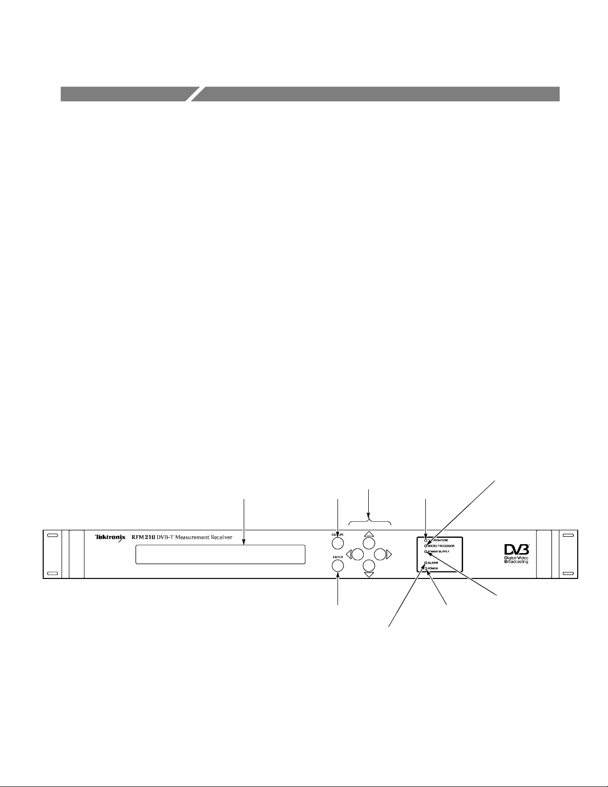
Front Panel Controls and Indicators
Menu Navigation
buttons
Display
Figure 1- 1: RFM210 DVB- T Measurement Receiver front panel display, controls and indicators
Display
The LCD display presents menus and measurement readouts.
Escape
Enter Power Indicator
Alarm Indicator
Temperature Indicator
Micro Processor Indicator
Power Supply
Indicator
RFM210 DVB-T Measurement Receiver User Manual
1- 1
Page 22

General Information
Escape
Enter
Menu Navigation Buttons
Used to move up a level within the menus.
Used to select choices within menus.
Used to change levels and select options within menus.
The following table describes the function of the front-panel LED indicators.
Table 1- 1: Front-panel LED indicators
Indicator Meaning when lit
Temperature The RFM210 internal temperature exceeds
normal parameters. Ensure that proper
clearance around the unit is provided for
cooling. If LED remains lit with proper
clearance, contact your local Tektronix Service
representative.
Micro Processor A micro processor fault has occurred. Contact
your local Tektronix Service representative.
Power Supply A power supply fault has occurred. Contact
your local Tektronix Service representative.
Alarm An Alarm condition has occured. See Alarm
Setup Menu on page 5--31 for more information on alarms.
Power Power is applied to the RFM210
1- 2
RFM210 DVB-T Measurement Receiver User Manual
Page 23
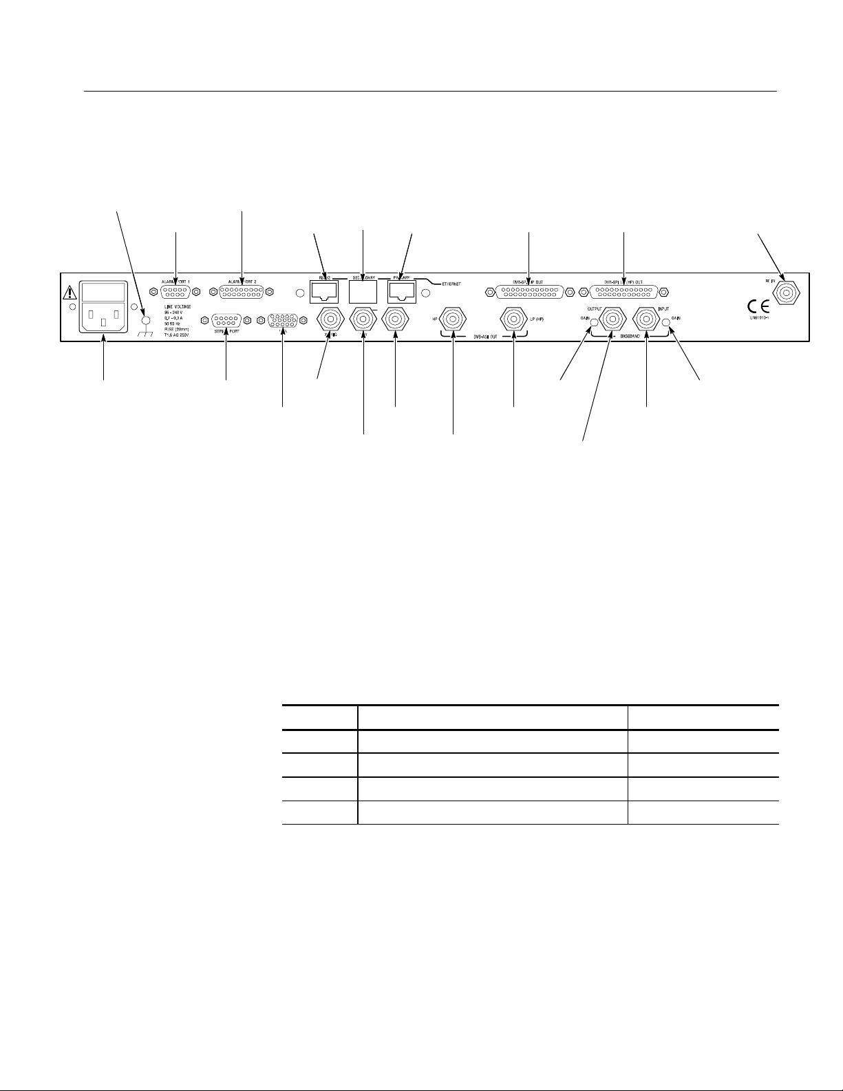
Rear Panel Connectors
General Information
Ground
Alarm Port 1
Power
Alarm Port 2
Serial Port
VGA
Tes t
X/TRIG
Secondary
(not used)
Y/W
Primary
(Ethernet)
Z
DVB--ASI
OUT LP (HP)
DVB--ASI
OUT HP
Figure 1- 2: RFM210 DVB-T Measurement Receiver rear panel connectors
Descriptions of the rear panel connectors are located in Table 6--2 on page 6--4.
DVB--SP
HP OUT
Gain Adjust
Baseband Output
DVB--SPI LP
(HP) OUT
Baseband Input
RF In
Gain Adjust
Options
Table 1--2 describes the configuration options available for the RFM210.
Table 1- 2: Instrument bandwidth/attenuation options
Option Description Default channel table
B6 6 MHz bandwidth USA008
B7 7 MHz bandwidth AUS013
B8 8 MHz bandwidth UK010
TN No attenuator n/a
Alternate channel tables can be loade provided they are for the same bandwidth.
See Appendix E, Channel Tables for more information.
RFM210 DVB-T Measurement Receiver User Manual
1- 3
Page 24
General Information
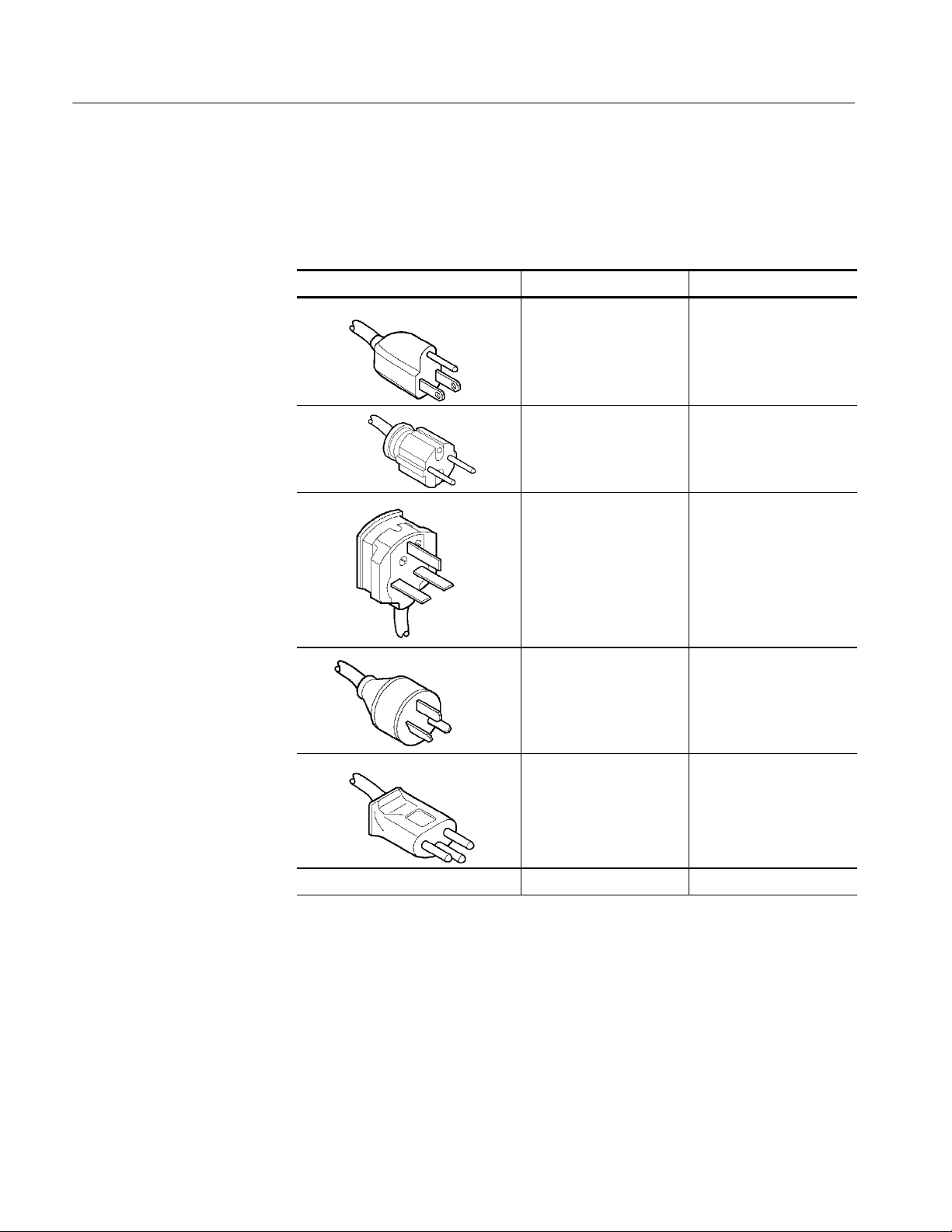
Table 1--3 describes the power cord options available for the RFM210. The
standard power cord is a Universal European plug configuration
Table 1- 3: Power cords available
Plug configuration Normal usage Option number
North America
125 V/15 A Plug
NEMA 5-15P
Europe
230 V
United Kingdom
230 V
Australia
230 V
A0
Standard
A2
A3
1- 4
Switzerland
230 V
No power cord supplied A99
A5
RFM210 DVB-T Measurement Receiver User Manual
Page 25

Installation
Page 26

Page 27
Installation
This chapter covers installation of the RFM210.
Checking the Environment Requirements
Read this section before attempting any installation procedures. This section
describes site considerations, power requirements, and ground connections for
your RFM210.
Site Considerations
Operating Requirements
The RFM210 requires no assembly and is designed to operate in standard
19-inch instrumentation rack. Always allow approximately 100 mm (4 inches) of
rear panel clearance for cable and power cord connections. Ensure that ventilation slots on the sides on the product are not obstructed and provide a free
airflow path.
CAUTION. Keep the sides of the RFM210 clear of obstructions to ensure proper
cooling.
The specifications in Technical Specifications, on page 6--1, list the operating
requirements for the RFM210. Power source, temperature, humidity, and altitude
are listed.
The unit is designed to operate from a single-phase power source having one of
its current-carrying conductors at or near earth ground (the neutral conductor).
Only the line conductor is fused for over-current protection.
Systems that have both current-carrying conductors live with respect to ground
(such as phase-to-phase on multiphase systems) must not be used as power
sources. A protective ground connection by way of the grounding conductor in
the power cord is essential for safe operation.
The mains outlets intended to supply the unit, should either be close to the unit
and easily accessible to the user or the unit mains inlet should be easily
accessible in the final installation.
RFM210 DVB-T Measurement Receiver User Manual
2- 1
Page 28

Installation
Powering On the RFM210
Perform the following step to power on the RFM210.
H Connect the power cord to the RFM210 and to the mains supply.
The RFM210 does not have a power switch. It will power up as soon as it is
connected to the m ains supply.
The RFM210 connects the chassis to the power cord safety ground. The chassis
is not designed to be “floated”. A rear-panel chassis ground screw is fitted, to
bond the product to a functional system ground if desired. This can be used to
improve chassis ground connections to other equipment.
2- 2
RFM210 DVB-T Measurement Receiver User Manual
Page 29

Introduction
Page 30

Page 31

DVB-T Transmission Principles
Transport
Stream
Coded Orthogonal Frequency Division Multiplexing (COFDM) is based on
phase / amplitude modulation using SINE / COSINE (Orthogonal) centered
carrier. The SINE / COSINE components are referred to as I / Q, (real /
imaginary). This system is an adaptation of I / Q data modulation.
COFDM
Modulator
Baseband
COFDM Signal
Up Converter
High Power
Amplifier
Encoded onto the I / Q data are two s ets of complex waveforms containing 1705
carriers in 2K IF FT (Inverse Fast Fourier Transform) mode and 6819 carriers in
8k IFFT mode. The amplitude and phase of all the carriers can be modulated. In
the 2K IFF T, there are 2048 I samples and 2048 Q samples sequentially
modulated on to a center carrier. This is referred to as a SYMBOL.
The 2048 I / Q samples are totally isolated (ORTHOGONAL) from each other,
because of the SINE / COSINE modulation. (In 2K mode, there are theoretically
2048 carriers available, however, in practice only 1705 carriers are used.) An
Inverse fast Fourier transform is calculated on both I and Q separately, providing
1705 separately generated carriers throughout the 2048 symbol period.
Each modulated I / Q carrier is described as a CONSTELLATION. (Thus, using
a 2048 I / Q sample system, 1705 different constellations conveying phase &
amplitude data can be modulated.) The data encoded onto the carriers is
randomized and spread throughout the frequency spectrum. In addition to this
FORWARD ERROR CORRECTION data is added to correct for data corruption.
RFM210 DVB-T Measurement Receiver User Manual
3- 1
Page 32

DVB-T Transmission Principles
3- 2
RFM210 DVB-T Measurement Receiver User Manual
Page 33
RFM210 DVB-T Measurement Receiver
The RFM210 fulfills a variety of roles for professional users in transmitter
performance monitoring or off-air signal monitoring of DVB-T services. It has
application in transmitter monitoring, field surveys, digital communications,
network performance monitoring, and as a general high quality off-air source of
MPEG transport streams (TS).
The RFM210 features include comprehensive TR 101 290 (formerly ETR290)
measurement, Constellation and Channel State display outputs and associated
Alarm outputs.
The receiver operates in accordance with ETSI EN 300 744. It provides both 2K
and 8K carrier options, supports all DVB-T modulation options, including the
hierarchical modes, and all guard interval options and FEC rates.
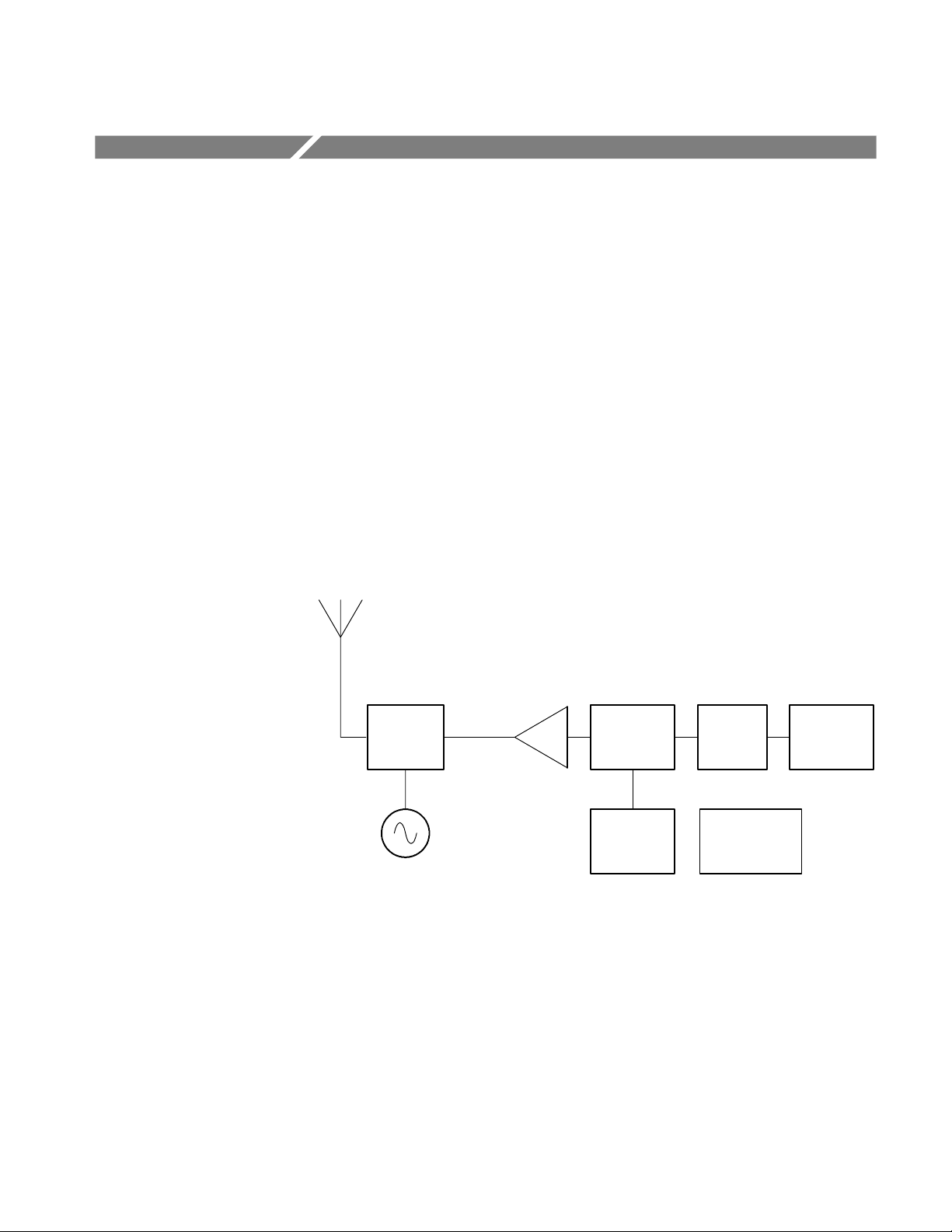
Functional Block Diagram
Baseband
Down
Converter
Modulated
I, Q Signal
ADC
COFDM
Demodulator
Digital Signal
Processor
Reed
Solomon
Decoder
Microprocessor
Control
Descrambler
The receiver accepts a UHF, VHF or external baseband input and demodulates
the COFDM signal to give an MPEG2 transport stream(s) output. The receiver
operates as a stand --alone system containing an embedded controller and DSP
(Digital Signal Processor), Alphanumeric display and keypad.
RFM210 DVB-T Measurement Receiver User Manual
3- 3
Page 34

RFM210 DVB-T Measurement Receiver
3- 4
RFM210 DVB-T Measurement Receiver User Manual
Page 35

Application Examples
Using the RFM210 in the Measurement and Monitoring of DVB-T Transmissions
This information provides a brief operational overview of the RFM210 Receiver
for three typical applications. Should you need advice for your DVB-T Measurement or Monitoring application please contact your local Tektronix representative.
Application A - Direct Measurement and Monitoring of Transmitters for Performance and Fault Diagnosis
Antenna
RFM210
Transmitter
To operate in this way a transducer fitted to the wave-guide provides a small RF
signal direct to the unit. (This signal level is required to match the specified
input level).
The RFM210 constantly monitors the performance of the transmission chain in
line with ETSI TR 101 290, and reports errors through the comprehensive Alarm
handling facilities and Windows support software.
RFM210 DVB-T Measurement Receiver User Manual
3- 5
Page 36
Application Examples
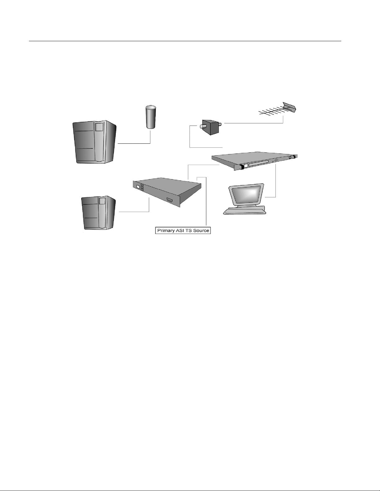
Application B - Provision of Standby Transport Stream (TS) at Transmitter Site
Through the Reception of Secondary Transmitted DVB-T Service
Remote Transmitter
Local Transmitter
Antenna
TS A/B Switch
CH Pass Filter
RFM210
For the RFM210 to operate correctly, we need to consider two points. One is the
presence and magnitude of other carriers in the VHF/UHF spectrum, and the
second is the signal input level. It is assumed that for this application the primary
function is the reliability of the standby path.
We recommend the receiving antenna be a high-gain directional design suitable
to provide the standby receiver with sufficient input level even if the transmitted
signal is low power for any reason, for example, maintenance. Consideration
must be given to the operational measurement window of the receiver in
acquiring reliable MER results.
3- 6
Next, we need to consider other carriers that could cause a disruption to the
receiver . The simplest way to ensure that the RFM210 responds only to the
required channel is to insert a channel pass filter at the RF input. Be sure to use a
quality filter, as a poor filter at this point can affect the measurement performance of the receiver.
RFM210 DVB-T Measurement Receiver User Manual
Page 37
Application Examples
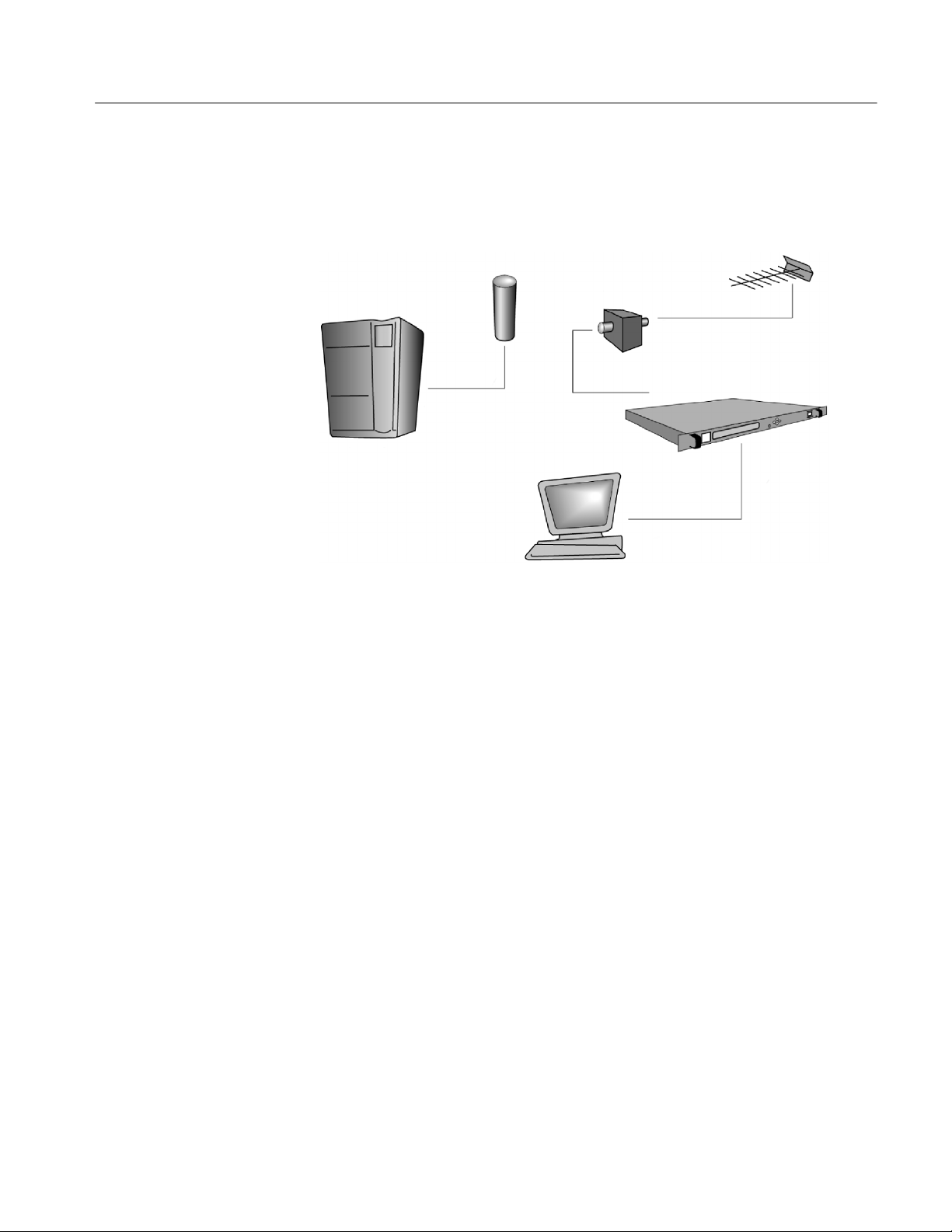
Application C - Reception Field Trials for the Collating of Measurement and Coverage Data
Antenna
Transmitter
The following paragraphs detail the considerations and approach to off-air
measurement and monitoring when using the RFM210 Receiver.
There are two important issues to consider in the acquisition of coverage data:
1. The application requires the measurement functions of the RFM210 and
therefore it requires sufficient input signal level in order to ensure that the
measurements are completed within the required ‘window’ of the receiver.
CH Pass Filter
RFM210
2. As a receiver is moved around a country its tuner will see a dynamic change
of RF carriers and strengths. In some localities and transmission networks
this issue of interfering carriers is more pronounced than others. Both
receivers in standard form have a wide band front end to the tuner. This
means that there is a potential for the automatic gain control (AGC) on the
tuner to be affected by the largest carrier that appears. This does not happen
with transmitter monitoring i.e. Application A.
This means that in the same way as in Application B, where we use channel
pass filtering to provide a safer environment for receiving a standby signal,
we need to do the same in this application to ensure the reliability and
repeatability of measurement data.
RFM210 DVB-T Measurement Receiver User Manual
3- 7
Page 38

Application Examples
Application Solutions for the RFM210 in Off-air Measurement and Monitoring
Solution 1
Solution 2
For the measurement and/or monitoring of one channel a single, quality, channel
pass filter is suitable. This filter should be positioned in series with the antenna
and any gain amplifier.
Suppose, for example, we are required to monitor approximately five DVB-T
Transmissions in a region. The best method is to use an RF amplifier driving the
five channel pass filters followed by a combiner. In this way the selective
filtering and the receiver may be moved to any area and once the input signal
level is assured, measurements can be taken with a high degree of i ntegrity.
RFM210
3- 8
RFM210 DVB-T Measurement Receiver User Manual
Page 39

Measurement
Page 40

Page 41

COFDM IQ Signal Analysis
The data transmitted using the COFDM modulation techniques are influenced by
distortions, which can cause irreparable errors in the modulator or in the
transmission link. Such errors are insufficient carrier suppression, phase and
amplitude errors within the baseband signals or noise, echoes or reflections and
multipath. In a real network, all of these effects coexist together, however, the
dominant impairments, in a DVB system, are noise and reflections.
Constellation diagrams allow baseband-modulating signals (I,Q) to be observed.
These show I amplitude versus Q amplitude at the symbol decision thresholds.
Normally a significant amount of symbols are used to produce such a diagram.
Many effects can be observed in a constellation diagram, such as noise,
interfering tone, IQ level imbalance, and others.
The noise and phase jitter, for instance, can be clearly recognized on the
constellation diagram but other interference contained in the signal can be only
recognize after precise evaluation of the transmission parameters. That is the
reason why several new measures have been introduced to quantify signal quality
and they are described in t he ETSI Technical Report TR 101 290. The RFM210
makes many of these measurements as part of its IQ analysis. These measurements are performed in 5 to 20 seconds, depending on the DVB-T parameters of
the received signal.
Modulation Error Ratio
Signal to Noise Ratio
The measurements calculated by the DSP are described in the following
paragraphs.
The Modulation Error R atio (MER) provides a single “figure of merit” analysis.
MER can be thought of as baseband SNR (Signal to Noise Ratio) in analog TV
systems. MER includes all type of signal impairment (not just noise), such as,
the effects of noise, carrier leakage, and IQ level and quadrature imbalance. The
MER is expressed as an average value in dB and percentage, and a peak value in
dB.
When the only error in the channel is noise, the ideal signal positions are
expanded to circular clouds. The difference between SNR and MER lies in which
perturbations of the received signal are included in the computation, so when the
only significant impairment is noise, SNR and MER are equivalent. SNR does
not account for modulation problems such as non-linearity, group delay and
flatness variation, filter mismatch and ingress. The unit of SNR is in dB.
RFM210 DVB-T Measurement Receiver User Manual
4- 1
Page 42

COFDM IQ Signal Analysis
System Target Error
(Mean and Deviation)
Amplitude Imbalance
Quadrature Error
Carrier Suppression
The displacement of the centers of the clouds in a constellation diagram from
their ideal symbol point reduces the noise immunity of the system and indicates
the presence of special kinds of distortions such as Amplitude Imbalance and
Quadrature Error. STE gives a global indication about the overall distortion
present on the raw data received by the system. System Target Error is a unitless
measure.
In the constellation diagram, an amplitude inequality is expressed as the
expansion of a signal component and compression of the other signal component. The Amplitude Imbalance separates the distortions of the I and Q signal in
amplitude from all other kind of distortions. The unit of Amplitude Imbalance is
in percentage (%).
The phase error is the phase angle between the cosine and sine components of
the carrier at 90_ in the modulator. If the two carriers that modulate the I and Q
signals are not orthogonal, a Quadrature error results. The unit of Quadrature
Error is in degrees (_).
The received channel should be flat across the band. For a 2K system, TPS
(Transmission Parameter Signalling) carriers are sent at the edge of band where a
transmitters output filter is not optimal.
Phase Jitter
For an 8K system, it is important that carrier suppression is good at the center
carrier, which is where the TPS carriers are sent.
A residual carrier is an unwanted coherent signal added to the center carrier of
the COFDM signal. It can be thought of as a special form of interference having
a frequency in the RF channel corresponding exactly to the carrier frequency. It
could be produced by DC offset voltages of the modulating I and/or Q signal or
by crosstalk from the modulating carrier within the modulator.
The Phase Jitter of an oscillator is due to fluctuations of its phase or frequency.
The phase jitter or phase noise is generated by converters in the transmission
path or by the I/Q modulator. In contrast to phase errors, phase jitter acts
simultaneously on the I and Q paths and its effect is that the carrier regeneration
cannot follow the phase fluctuations. The Phase Jitter is in degrees (_).
4- 2
RFM210 DVB-T Measurement Receiver User Manual
Page 43

Bit Error Measurement
Pre-Viterbi Bit Error Ratio
Post-Viterbi Bit Error Ratio
UCE Error Rate
(Post Reed Solomon)
Uncorrectable Errors
(UCE)
Remote BER logging
This is calculated from the number of bits corrected by the Viterbi decoder in
each second. The methodology for calculation defines the maximum pre-Viterbi
BER value as 1.67 × 10
This value is calculated from the number of bits corrected by the Reed-Solomon
decoder in each second, and is the most commonly quoted BER figure. A BER
as great as 2× 10
as the Quasi Error Free (QEF) point.
This gives the number of uncorrectable Errors (UCE) currently being detected in
each second. A poor RF channel results in too many errors for the Viterbi and
Reed Solomon decoders to correct. If UCEs are present, the MPEG decoded
pictures will become severely corrupted or completely lost.
This provides an accumulated count of all the Un-correctable errors (UCE) since
the error counter was last reset manually. The UCE count display within the
Monitoring Menu provides a Date Time stamp at the point of the last count reset.
The receiver can also provide BER data, via the Serial Port, for remote logging
on a PC or terminal. The current values of pre and post Viterbi BER, and the
UCE are available on demand.
-- 4
-- 2
, even though the real BER could be greater in value.
will still give a good decoded picture, and this rate is known
RFM210 DVB-T Measurement Receiver User Manual
4- 3
Page 44

Bit Error Measurement
4- 4
RFM210 DVB-T Measurement Receiver User Manual
Page 45

Operation
Page 46

Page 47

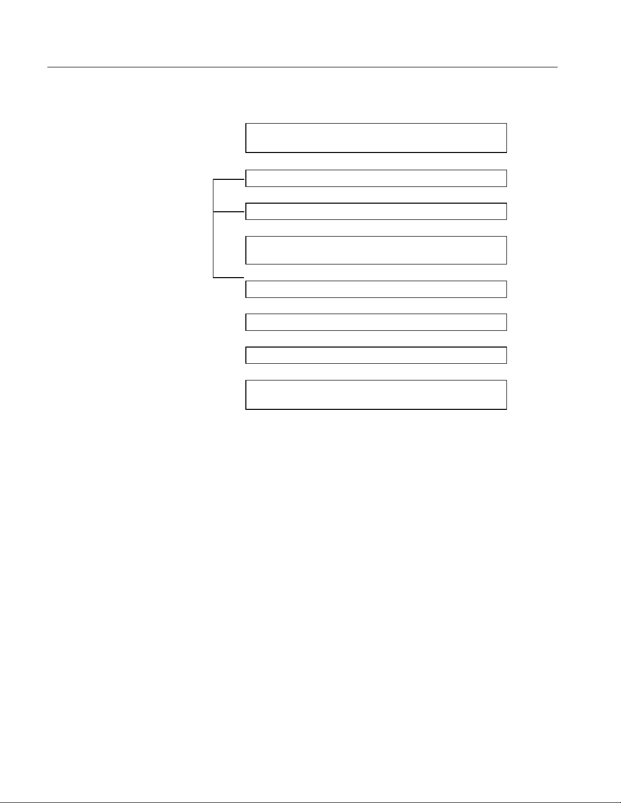
Initial Set-up
Menu Operation
In general, the two front panel switches labelled with up and down arrows YB
select the different screens, while the two front panel switches labelled with the
left and right arrows
highlighted (where applicable). Having highlighted an option, it is then
necessary to press the ENTER key to actually implement the selection. The
ESCAPE key is used to go up a menu level or to cancel parameter level settings.
Under some menu options, pressing ENTER allows setting of a parameter level.
While setting levels, the user is unable to scroll through the menu options until
level setting is complete by pressing ENTER (or ESCAPE to cancel). The
following section will give details of each displayed screen and their meaning.
The RFM210 receiver operates a number of Menu driven options. These are
classified into seven Menu headings and provide access to the vast majority
settings and control options of the unit.
A"allow the various options within the screen to be
Main Screen
On power-up the Main Screen displays the primary information of Channel
selection, Carrier Level, and UCE Count. In addition, the primary TR 101 290
measurements of MER and SNR are displayed, and alternated with the BER
measurement. The delay between display of MER/SNR and BER is 8 seconds.
Pressing the l eft and right arrows
ment to be displayed without waiting for the display timer. Normally when BER
is displayed the pre-Viterbi BER measurement will be shown. If the signal
quality degrades to such an extent that post-Viterbi BER is greater than zero it is
the post_viterbi BER level that is displayed. If baseband input is selected, this is
indicated on the main screen and the Channel selection and Carrier Level
indications are removed. If the unit is not synchronized for any reason, this is
indicated on the main screen and in this case the measurements are not displayed. You access the receiver’ s available menus from this screen with up and
down arrows
YB .
A"at any time allow the alternative measure-
RFM210 DVB-T Measurement Receiver User Manual
5- 1
Page 48

Initial Set-up
Security Menu
DVB Options Menu
Options available within the Security Menu allows you to:
1. Lock
2. Unlock
The lock facility prevents an operator from changing DVB-T or System
parameters while the unit is locked. In order to select or change settings within
the following menus it is required to unlock the unit. The lock status is stored so
that unlocking is not required every time the unit is powered up.
Options available within the DVB Options menu are:
1. Select Channel
System Options Menu
2. Modulation Options
3. FEC Settings
4. Hierarchical Mode
5. No of Carriers
6. Guard Interval
7. Select Programmed Channel
Options available within the System Options Menu:
1. Phase Correction
2. Equalizer Window
3. COFDM Spectrum
4. Time Date Setting
5. Set LCD Contrast
5- 2
6. Remote Comms Setting
7. IP Address
8. Program Channels
RFM210 DVB-T Measurement Receiver User Manual
Page 49

Input/Output Options Menu
Options available within the Input/Output Options Menu:
1. Input Source
2. ASI Output Mode
3. Transport Stream Setting (188/204 bytes)
4. Monitor Output
5. Constellation Mode
6. Single Carrier Setting
Monitoring Menu
Options available within the Monitoring Menu:
Initial Set-up
Alarm Setup Menu
1. I/Q Measurements*
2. Frequency Response Measurements
3. Pre/Post-Viterbi BER
4. Channel State Information (CSI)
5. Carrier Level**
6. Sync Lock Status
7. UCE, UCE Total Measurements
8. Fault History Select*
9. System Status Select*
* Pressing ENTER in these menu options selects lower level menus as described below.
** Not displayed if set to Baseband Input
Options within the Alarm Setup Menu:
1. Set Alarm Relays 1 and 2*
2. SetOpenCollectorAlarms1to8*
3. Set Warning/Fault logs*
*Pressing ENTER under any of these options allows detailed setup of the selected alarm.
RFM210 DVB-T Measurement Receiver User Manual
5- 3
Page 50

Initial Set-up
DSP Setup Menu
Fault History Menu
Selected when ENTER is pressed under the measurement menu, IQ measurement
option.
Options within the DSP Setup Menu:
1. Low/High Carrier Setting
2. Symbols Setting
3. END Calibration Setup
4. Transmitter/Receiver Setting
Selected when ENTER is pressed under the measurement menu, Fault History
option.
System Status Menu
Options within the Fault History Menu:
1. View Log
2. Clear Log
Selected when ENTER is pressed under the measurement menu, System Status
option.
Options within the System Status Menu:
1. V iew Alarm Status
2. View Power Supply Status
3. V iew Internal Temperature
4. View Product Information
5- 4
RFM210 DVB-T Measurement Receiver User Manual
Page 51

Output to VGA Monitor
Initial Set-up
You can get a quick view of the instrument settings and measurements by
connecting a monitor to the VGA connector on the rear panel. An example
readout is shown in Figure 5--1.
Time/Date
18:46:20
24--Aug--01
Signal Parameter
Channel : 50
Modulation : 64QAM
Hierarchy : Non-- H
COFDM Mode : 2K
Guard Int. : 1/32
Code rate : 2/3
Uncorrected Errors
UCE (total) : 01028
UCE (rate) : 0000
BER Measurements
Post Viterbi : 0.00s+00
Pre Viterbi : 1.98s--06
Channel State Info.
CSI Avgs : 013%
CSI Peak : 000
IO Measurements
MER : 28.52 dB
MER (rms) : 03.75 %
MER (p--p) : 019.25 dB
STEM : 1.09s--83
STED : 5.16s--84
Ampl. Imb : 0.0022 %
Quad. Err : 0.0019’
Carr. Supp : 69.78dB
Phase Jitt : 0.2265’
SNR : 28.50 dB
ENM : 09.93 dB
IQ Settings
Symbols : 0200
Lo Carrier : 0000
Hi Carrier : 1512
Freq. Measurements
Freq (mean) : +0.13 dB
Freq (p--p) : 1.98 dB
TEKTRONIX RFM 2 10 DVB--T
Figure 5- 1: Example of output to VGA monitor
RFM210 DVB-T Measurement Receiver User Manual
5- 5
Page 52

Initial Set-up
5- 6
RFM210 DVB-T Measurement Receiver User Manual
Page 53

Main Screen
The main screen provides the values of the most important parameter measurements, as well as the current channel setting and signal strength. A scrolling
display, (8 second delay) alternates between the Pre- or Post-Viterbi BER value,
and MER and SNR. It is possible to toggle between the measurement displays
without waiting for the delay to time out by pressing the ENTER key.
Channel: 28L Carrier Level: HHHHhhh
BER > Viterbi: 3.40e-05 UCE: 0000
Channel: 28L Carrier Level: HHHHhhh
MER: 28.5dB SNR: 29.1dB UCE: 0000
In the case of the BER display, whether Pre- or Post-Viterbi BER is shown
depends on the value of Post-Viterbi BER. With a good signal, Post-Viterbi BER
will be zero, and the Pre-Viterbi BER value is shown. If the signal degrades to
such an extent that you start to get Post-Viterbi errors, this is what will be
displayed on the Front Panel.
If the unit is set to External Baseband input, this is indicated on the Main Screen
and the channel setting and Carrier Level indications are not shown, as they do
not apply for baseband input signals. If the unit i s not in sync this is also
indicated on the front panel. Measurements are not valid if the sync is lost and
are therefore not shown.
Pre-Viterbi BER is calculated from the number of bits corrected by the Viterbi
decoder each second and post-Viterbi BER is calculated from the number of bits
corrected by the Reed-Solomon decoder in each second. Post-Viterbi BER is
generally the most useful BER figure. This screen also shows the number of
UnCorrectable Errors (UCE) currently being detected in each second. If there are
uncorrected errors present, then the BER cannot provide a true measure. A
Post-Viterbi BER as great as 2×10
good decoded picture, and this is known as the Quasi Error Free (QEF) point.
The carrier level bargraph gives an indication of received signal strength. The
first or left bar indicates >35 dBmV when filled, with each following bar a further
5 dB step. When 65 dBmV is reached, all bars are filled. Note the signal strength
refers only to the signal applied to the RF input connection and not the baseband
input source.
If the unit is set to show any other screen (except any screen under the monitoring menu), it will return to the main menu if no key is pressed within 60 seconds.
-- 4
(displayed as 2.00e--04) will still give a
RFM210 DVB-T Measurement Receiver User Manual
5- 7
Page 54

Main Screen
5- 8
RFM210 DVB-T Measurement Receiver User Manual
Page 55

Security Menu
The Security screen allows the user to unlock or l ock the unit. When the unit is
locked the user will be unable to change any of the parameters via t he front
panel, although it is still possible to change parameters through the remote
comms. It is possible to change the channel via the front panel when the unit is
locked, either through the main screen, the channel change screen or the
pre-programmed channel screen. The locked status is stored.
Main Screen to Security Menu
Main
Screen
Y f B
Channel: 28L Carrier Level:
BER > Viterbi: 3.40e-05 UCE:0000
YB
Security Menu ENTER
YB
Alarm Setup Menu
YB
Monitoring Menu
YB
Input/Output Options Menu
YB
System Options Menu
YB
DVB Options Menu
HHHHHhhh
RFM210 DVB-T Measurement Receiver User Manual
5- 9
Page 56
Security Menu
Main
Screen
Main
Screen
Channel: 28L Carrier Level:
BER > Viterbi: 3.40e-05 UCE:0000
Y f B
Enter:Unlock Escape:Cancel ENTER
OR
Enter:Lock Escape:Cancel ENTER
B
Enter Key Sequence: ENTER
B
Incorrect Key Sequence
OR
Unit Unlocked
OR
Unit Locked
Channel: 28L Carrier Level:
BER > Viterbi: 3.40e-05 UCE:0000
HHHHHhhh
SEQ
B (After 1 sec delay)
HHHHHhhh
Procedure to Lock or Unlock the Receiver
Depending on the current condition, the user is presented with one of the
following screens:
Enter: Unlock Escape: Cancel
Enter: Lock Escape: Cancel
Pressing ENTER changes the display to the following screen allowing the user
to enter the required four key sequence to Lock/Unlock the unit.
Enter Key Sequence:
The user must enter the correct key sequence (using the
keys) to lock/unlock the unit. As each key is pressed an asterisk ‘*’ is displayed
to acknowledge the key pressed.
If the incorrect key sequence is entered the following message is displayed for a
short period before being returned to the Lock/Unlock option above.
Incorrect Key Sequence
Y, ", A, B and ENTER
5- 10
RFM210 DVB-T Measurement Receiver User Manual
Page 57

Security Menu
If the correct key sequence was entered one of the following messages is
displayed (whichever is appropriate) for a short period before returning to the
main menu.
Unit Unlocked
Unit Locked
The ESCAPE key can be used at any time to abort the unlocking sequence and
return to the main menu.
The required key sequence for all units is
Y, ", A, B.
RFM210 DVB-T Measurement Receiver User Manual
5- 11
Page 58

Security Menu
5- 12
RFM210 DVB-T Measurement Receiver User Manual
Page 59

DVB Options Menu
Main Screen to DVB Options Menu
To access the DVB Options menu, press the front-panel navigation buttons to
display the DVB Options menu and t hen press the ENTER key.
Main
Screen
Channel: 28L Carrier Level:
BER > Viterbi: 3.40e-05 UCE:0000
Y f B
HHHHhhh
YB
Security Menu
YB
Alarm Setup Menu
YB
Monitoring Menu
YB
Input/Output Options Menu
YB
System Options Menu
YB
DVB Options Menu ENTER
RFM210 DVB-T Measurement Receiver User Manual
5- 13
Page 60

DVB Options Menu
Main
Screen
Channel: 28L Carrier Level:
HHHHhhh
BER > Viterbi: 3.40e-05 UCE:0000
YB
Programme:(1)23456 Channel:28L
Currently set to Prog: 1 Channel: 28L
YB
Guard Interval: (1/32) 1/16 1/18 1/4
Currently set to: 1/32
YB
COFDM Carrier Mode: (2K) 8K
Currently set to: 2K
YB
Hierarchy: (nonèH) a=1 a=2 a=4
Currently set to: NonèHierarchical
YB
LP Code Rate: 1/2 2/3 3/4 5/6 7/8
Currently set to: 2/3
YB
HP Code Rate: 1/2 2/3 3/4 5/6 7/8
Currently set to: 2/3
YB
MOD Options: (QPSK) 16QAM 64QAM
Currently set to: 64QAM
YB
Current Channel Setting: (28L)
Currently set to: 28L
5- 14
Y f B
Current Channel Setting: (28L)
Set to Channel: 28L
Pressing ENTER allows the channel to be changed. The high bit of the channel
indication starts flashing when ENTER is pressed indicating that the channel
can be incremented or decremented in steps of 10. Pressing the Left & Right
arrows
A"moves the cursor position allowing adjustment of the l ow bit and
offset. Pressing the Up and Down arrows increments or decrements the channel
at the cursor position. If the channel is adjusted above the maximum or below
the minimum allowable, the channel will scroll over accordingly .
RFM210 DVB-T Measurement Receiver User Manual
Page 61

DVB Options Menu
Once the required channel and offset has been selected on this screen, pressing
ENTER will set the new channel. The Current Channel S etting indication will
update on completion of the channel change.
If channel offsets are not available these are not displayed and cannot be set.
Programme: (1) 23456 Channel: 28L
Currently set to Prog: 1 Channel: 28L
The unit stores 6 pre--programmed channels. Left & right arrows
A"highlight
the option 1 to 6 and the channel setting of the highlighted option is displayed on
the right. ENTER selects the highlighted option and after successful setting the
display is updated. If the channel had previously been set via the serial communications or through the main screen or channel setting s creen, the current
program setting indication will be blank. See Configuration Menu section for
details of how to change the 6 programme settings.
Guard Interval: (1/32) 1/16 1/8 1/4
Currently set to: 1/32
The guard interval is a parameter of the transmitted signal and therefore the
receiver must be set accordingly. Left & right arrows
A"highlight the option,
while ENTER makes the selection.
COFDM Carrier Mode: (2K) 8K
Currently set to: 2K
The carrier mode (2K or 8K) is a parameter of the transmitted signal and
therefore the receiver must be set accordingly. Left & right arrows
A"highlight
the option, while ENTER makes the selection.
RFM210 DVB-T Measurement Receiver User Manual
5- 15
Page 62

DVB Options Menu
Hierarchy: (Non-H) a=1 a=2 a=4
Currently set to: Non-Hierarchical
The receiver is capable of receiving hierarchical modulation modes. The “a”
parameter in the Hierarchy screen refers to the scaling factor. Left & right arrows
A"highlight the option, while ENTER makes the selection.
LP Code Rate: 1/2 2/3 3/4 5/6 7/8
Currently set to: 2/3
YB
HP Code Rate: 1/2 2/3 3/4 5/6 7/8
Currently set to: 2/3
The Forward Error Correction (FEC) rate is also a parameter of the transmitted
signal and therefore the receiver must be set accordingly. Normally the unit will
automatically detect and set these parameters from the received TPS carriers, but
it can be set manually through this menu option. In non-hierarchical mode the
LP Code Rate setting has no effect. Left & right arrows
A"highlight the option,
while ENTER makes the selection.
MOD Options: (QPSK) 16QAM 64QAM
Currently set to: 64QAM
The modulation option is a parameter of the transmitted signal and therefore the
receiver must be set accordingly. Normally the unit will automatically detect and
set this parameter from the received TPS carriers, but it can be set manually
through this menu option. Left & right arrows
A"highlight the option, while
ENTER makes the selection.
5- 16
RFM210 DVB-T Measurement Receiver User Manual
Page 63

System Options Menu
Main Screen to System Options Menu
To access the System Options menu, press the front-panel navigation buttons to
display the S ystem Options menu and then press the ENTER key.
Main
Screen
Channel: 28L Carrier Level:
BER > Viterbi: 3.40e-05 UCE:0000
Y f B
HHHHhhh
YB
Security Menu
YB
Alarm Setup Menu
YB
Monitoring Menu
YB
Input/Output Options Menu
YB
System Options Menu ENTER
YB
DVB Options Menu
RFM210 DVB-T Measurement Receiver User Manual
5- 17
Page 64

System Options Menu
Main
Screen
Channel: 28L Carrier Level:
HHHHhhh
BER > Viterbi: 3.40e-05 UCE:0000
Y f B
Change Programme:(1)23456
Currently set to Channel: 21L
YB
Ethernet IP Address: 192.9.200.100
Enter to change
YB
Remote Comms.: (RS232) Ethernet
Currently set to: RS232
YB
Set LCD Contrast: Min HHHHhhhhhhh Max
A"to adjust Enter to store
YB
Push Enter to set time and date
Currently set to: 08èAugè01 17:03:25
YB
COFDM Spectrum: (normal) Inverted
Currently set to: Normal
YB
Equalizer Window: (Left Aligned) Center
Currently set to: Left Aligned
YB
Phase Correction: (Enabled) Disabled
Currently set to: Enabled
5- 18
Y f B
Change Programme: (1)23456
Currently set to Channel: 21L
This option allows setting of the 6 pre-programmed channels. Left & right
arrows
A"scroll through the 6 settings and the current setting for the high-
lighted programme is shown. ENTER allows the highlighted selection to be
adjusted. The high bit of the channel indication starts flashing indicating that the
channel can be incremented or decremented in steps of 10. Pressing the Left &
Right arrows
A"moves the cursor position allowing adjustment of the low bit
and offset. Pressing the Up and Down arrows increments or decrements the
channel at the cursor position. If the channel is adjusted above the maximum or
RFM210 DVB-T Measurement Receiver User Manual
Page 65

System Options Menu
below the minimum allowable, the channel will scroll over accordingly . Pushing
ENTER again sets the channel for the highlighted preset programme.
Ethernet IP Address: 192.9.200.100
Enter to change
This screen displays the IP address of the Ethernet module. The IP address is
read by the RFM210 on power up. This menu option also provides t he ability to
change the IP address. Pressing ENTER changes the display and causes the first
character of the first segment of the IP address to flash. The up down arrows
YB
change the value of the selected character, with values for each segment ranging
from 0 to 255. The left and right arrows
A" move the cursor to set other
segments. Press ENTER set the IP address. Pressing ESCAPE cancels the
configuration change and reverts back to the original setting.
Remote Comms.: (RS232) Ethernet
Currently set to: RS232
This menu selects whether the RS232 serial port or Ethernet Interface is active.
Left and right arrows
A"highlight the option, while ENTER makes the
selection.
Set LCD Contrast: Min HHHHhhhhhhh Max
A" to adjust Enter to store
Use this option if the contrast of the LCD display is too light or too dark. The
left and right arrows
A"change the setting (left to make the screen lighter, right
to make the screen darker). Once the required contrast is achieved, press
ENTER to store this setting. If the m enu is changed (by either the up down
arrows
YB,ortheESCAPE key) without first storing the setting, the contrast
will revert to the previous setting.
Push Enter to set time and date
Currently set to: 08-Aug-01 17:03:25
The receiver incorporates a real-time clock, primarily for use during automated
logging via the Remote Comms. Pushing ENTER allows the time and date to be
reset. The flashing item indicates the current selection and this can be adjusted
using the up down arrows
RFM210 DVB-T Measurement Receiver User Manual
YB, while the left and right arrows A" change the
5- 19
Page 66

System Options Menu
selected item. Note that the clock stops while adjustment is being carried out to
allow accurate setting of the seconds. Pushing ENTER again starts the clock and
allows scrolling of the menu.
COFDM Spectrum: (Normal) Inverted
Currently set to: Normal
If the COFDM signal is spectrally inverted during the up-conversion it will be
necessary to set this option to Inverted, otherwise Normal must be selected. Left
& right arrows
A"highlight the option, while ENTER makes the selection.
Equalizer Window: (Left Aligned) Centered
Currently set to: Left Aligned
This option selects the range, over which echoes can be equalized. Normally the
centered aligned option is selected. The option positions the window for best
results in the tolerance to delayed echoes. Left & right arrows
A"highlight the
option, while ENTER makes the selection.
Phase Correction: (Enabled) Disabled
Currently set to: Enabled
This option enables or disables the common phase correction capability of the
COFDM demodulator devices. Left & right arrows
A"highlight the option,
while ENTER makes the selection.
5- 20
RFM210 DVB-T Measurement Receiver User Manual
Page 67

Input/Output Options Menu
Main Screen to Input/Output Options Menu
To access the Input/Output Options menu, press the front-panel navigation
buttons to display the Input/Output Options menu and then press the ENTER
key.
Main
Screen
Channel: 28L Carrier Level:
BER > Viterbi: 3.40e-05 UCE:0000
Input/Output Options Menu ENTER
Y f B
HHHHhhh
YB
Security Menu
YB
Alarm Setup Menu
YB
Monitoring Menu
YB
YB
System Options Menu
YB
DVB Options Menu
RFM210 DVB-T Measurement Receiver User Manual
5- 21
Page 68

Input/Output Options Menu
Main
Screen
Channel: 28L Carrier Level:
HHHHhhh
BER > Viterbi: 3.40e-05 UCE:0000
Y f B
Single Carrier : (0034)
Change to: (0034) Enter/
A"to Change
YB
Constellation Mode.: (Single) All
Currently set to: Single
YB
Monitor Output: (Constltn) Chan State
Currently set to: Constltn
YB
Transport Stream: (188 Bytes) 204 Bytes
Currently set to: 188 Bytes
YB
ASI Output Mode: (Burst) Byte
Currently set to : Burst
YB
Input Source: (Int Tuner) Ext Baseband
Currently set to: Int Tuner
Y f B
5- 22
Single Carrier: (0034)
Change to: 0034 Enter/
A" to change
When the single carrier constellation display option is selected, this screen
enables a particular carrier to be chosen. In 2K carrier modes, the carriers are
numbered from 0 to 1704 (1705 in total); in 8K modes, the carriers are numbered
from 0 to 6816 (6817 in total). ENTER allows the selected carriers to be
changed. The flashing digit indicates which bit will be incremented or decremented by the Up and Down arrows. The Left & right arrows
A"move the cursor
position. Pushing ENTER once more makes the selection. If the number is
adjusted above the maximum allowable value or below 0 the value will scroll
over.
Pressing the Left & Right arrows A" without pressing ENTER is a convenient
method of selecting between adjacent carriers (
A decrements the carrier number
RFM210 DVB-T Measurement Receiver User Manual
Page 69

Input/Output Options Menu
and
" increments the carrier). If the number is adjusted above the maximum
allowable value or below 0 the value will scroll over.
Constellation Mode.: (Single) All
Currently set to: Single
When the constellation diagram is selected, the receiver shows either the
superimposed constellations of all the carriers, or the constellation of a specific
single carrier. This i s applicable only to the oscilloscope output and not the
constellation display on the VGA output. Left & right arrows
A"highlight the
option, while ENTER makes the selection.
Monitor Output: (Constltn) Chan State
Currently set to: Constltn
The receiver provides the option of displaying either the constellation diagram or
the channel state information display. To view either type, an oscilloscope must
be connected to the X/TRIG, Y/W outputs of the receiver. See page 5--43 for
connection information. The above screen allows selection of the required
option. This selection also affects the display shown on the VGA output. Left &
right arrows
A"highlight the option, while ENTER makes the selection.
Transport Stream: (188 Bytes) 204 Bytes
Currently set to: 188 Bytes
This screen allows the user to select packet lengths of 188 or 204 bytes. Left &
right arrows
A"highlight the option, while ENTER makes the selection.
ASI Output Mode: (Burst) Byte
Currently set to : Burst
This option selects whether of the ASI transport stream Output is in Burst or
Byte format. Note that the LVDS outputs are not affected by the setting of the
ASI Output mode. Left & right arrows
A"highlight the option, while ENTER
makes the selection.
RFM210 DVB-T Measurement Receiver User Manual
5- 23
Page 70

Input/Output Options Menu
Input Source: (Int Tuner) Ext Baseband
Currently set to: Int Tuner
This option selects the input signal source. If the unit is set to Int Tuner, the
output is derived from the signal applied to the RF input connection via the
internal UHF/VHF tuner. If the unit is set to Ext Baseband, the output is derived
from the signal applied to the Baseband input connection. Left and right arrows
A"highlight the option, while pressing ENTER makes the selection.
5- 24
RFM210 DVB-T Measurement Receiver User Manual
Page 71

Monitoring Menu
The monitoring screens allow the user to view the status of the receiver and the
quality of the signal being received.
Main Screen to Monitoring Menu
To access the Monitoring menu, press the front-panel navigation buttons to
display the Monitoring menu and then press the ENTER key.
Main
Screen
Y f B
Channel: 28L Carrier Level:
BER > Viterbi: 3.40e-05 UCE:0000
YB
Security Menu
YB
Alarm Setup Menu
YB
Monitoring Menu ENTER
YB
Input/Output Options Menu
YB
System Options Menu
YB
DVB Options Menu
HHHHhhh
RFM210 DVB-T Measurement Receiver User Manual
5- 25
Page 72

Monitoring Menu
Main
Screen
Channel: 28L Carrier Level:
HHHHhhh
BER > Viterbi: 3.40e-05 UCE:0000
Y f B
Press Enter to View
System Status Screens
YB
Fault History: (View Log) Clear Log
Scroll Through Log
YB
Monit Demod: UCE: 0000 Count: 01453 A"
Reset at 11:40:01 08-Aug-01 (Reset)
YB
Monit: TPS Frq Clk FFT Frm FEC2 FEC3 A"
nnnnnn n
YB
Carrier Level: HHHHHHHhhhh
YB
CSI Average: HHHHhhhhhh
CSI Av: 40% CSI Peak: 000
YB
BER Post Vit.: h hhhhhhhh 0.003+00
BER Pre Vit.:
H HHHhhhhh 2.82e-03
YB
Frequency Response
Mean:+0.21dB PkèPk:2.40dB
YB
IQ measurements A":Scroll Enter:Set
MER:28.26dB MER(rms):03.88%
Y f B
Press Enter to View
System Status Screens
Pressing the ENTER key enters the System Status menu.
5- 26
RFM210 DVB-T Measurement Receiver User Manual
Page 73

Monitoring Menu
Fault History: (View Log) Clear Log
Scroll Through Log
This menu option allows the user to View or Clear details of the 100 logged
faults as determined by the setup of the logging parameters.
Use the left & right arrows
A"to select the required option and ENTER to
view/clear the log.
When ‘View Log’ is selected, details of the latest log are shown. An example is
given below:
4448 S/N Ratio Status: Failure Alarmed
Level: 27.1dB 15:05:27 07-Aug-01
The screen shows the following:
The log number (0000 -- 9999);
The parameter for which the log was made;
Whether the log is for a Warning or Failure alarm;
Whether the log is made for an alarm occurrence or an alarm clear;
The Level of the parameter at the time of the log event;
The Time and Date of the Log.
If no Log events are stored the message “No F aults Logged” is displayed.
Use the up down arrows
arrow
Y is pressed while details of the latest Log are shown, the earliest Log
event is shown. Similarly, if the down arrow
YBto scroll through the stored log events. If the up
B is pressed while details of the
earliest Log are shown, the latest Log event is shown. If further Log events occur
whilst in this menu option, the display is not updated unless the earliest log
event is being viewed and becomes overwritten.
Pressing ENTER returns to the latest stored log event.
Pressing ESCAPE returns to the Monitoring Menu option.
When ‘View Log’ is selected the following screen is displayed:
Confirm Clear Fault Log:
Enter: Clear Escape: Cancel
Pressing ENTER clears the stored Log and returns to the Monitoring Menu
option.
Pressing ESCAPE cancels the clear Log option and returns to the Monitoring
Menu option.
RFM210 DVB-T Measurement Receiver User Manual
5- 27
Page 74

Monitoring Menu
Monit Demod: UCE:0000 Count:01453
A"
Reset at 11:40:01 08-Aug-01 (Reset)
This screen shows the number of UnCorrectable Errors (UCE) per second; that
is, the post Reed-Solomon error rate. The screen also provides a running count of
the number of UCEs since it was last reset.
Use the left & right arrows
A"to view the UCE and Total Error count of the
three Demodulator devices in the unit.
When hierarchical modes are being received the UCE monitoring applies to the
high priority (HP) stream for the Monitoring and HP Demodulator devices and
the LP stream for the LP Demodulator.
ENTER resets the UCE counter for all 3 devices.
Monit: TPS Frq Clk FFT Frm FEC2 FEC3
nnnnnnn
A"
This screen shows the current status of various synchronization parameters of the
demodulator devices:
TPS Transmission Parameter Signalling is correct.
Frq The receiver is frequency-locked to the received signal.
Clk The sampling frequency synchronization is locked to the
received signal.
FFT The Start FFT window synchronization is OK.
Frm The Frame synchronization i n the demodulator is OK.
FEC2 Deinterleaver/R-S decoder is synchronized.
FEC3 Descrambler is synchronized.
5- 28
Use the left & right arrows
A"to view sync status of the three Demodulator
devices in the unit.
Carrier Level: HHHHHHHhhhh
This screen gives an indication of the strength of the received RF signal, and is
similar to the bargraph displayed on the main screen. When the received signal is
greater than --65 dBmV the first bar is filled. More bars are filled as the signal
strength increases and all bars are filled when a signal strength of --35 dBmVis
reached. Note that this is only applicable to signals applied to the internal tuner.
When baseband input is selected this menu option is not available.
RFM210 DVB-T Measurement Receiver User Manual
Page 75

Monitoring Menu
CSI Average: HHHHhhhhhh
CSI Av: 40% CSI Peak: 000
The Channel State Information (CSI) score is a measure of the amount of noise
and interference present in the ensemble. For a Gaussian channel, the CS I Av is
related to the system Equivalent Noise Floor (ENF) by the empirical formula.
ENF = 20(K-C),
Where K = 2.676 and C = log10 (CSI Av %).
For example, 10% CSI Av is equivalent to --33.5 dBc ENF.
The CSI Average bargraph scale is calibrated such that each bar is equivalent to
10% but offset to show the average. Thus, with three bars filled the CSI average
is greater than 25% but less than 35%. The CSI score is calculated by averaging
the CSIs of all the data carriers over a symbol period.
The ‘CSI peak’ refers to the number of carriers, which exceed a CSI score of
62.5%.
BER Post Vit.: h hhhhhhhh 0.003+00
BER Pre Vit.: H HHHhhhhh 2.82e-03
This screen provides a simple display of the pre- and post-Viterbi BER. The first
(separated) bar on the bargraph display indicates that pre- or post-Viterbi errors
are present.
The post-Viterbi bargraph scale has high sensitivity and is centered about a BER
of 2× 10
-- 4
(displayed as 2.00e--04) which is the QEF point. If the bars are
unfilled, then the BER is below the QEF point; if they are filled, then the BER
exceeds the QEF point. The BER monitoring applies to the high priority (HP)
stream when hierarchical modes are being received.
The pre_Viterbi bargraph is scaled linearly from 0 to a BER of 1.67× 10
-- 2
(displayed as 1.67e--02). Due to the way the pre-Viterbi BER is calculated the
maximum possible value is 1.67×10
-- 2
even though the real BER could be greater
than this.
Frequency Response
Mean: +0.21dB Pk-Pk: 2.40dB
This screen displays the latest frequency response measurement. The measurement is taken once every 5 measurements of IQ data. A frequency response
measurement results in a m omentary break-up on the constellation output on the
RFM210 DVB-T Measurement Receiver User Manual
5- 29
Page 76

Monitoring Menu
VGA monitor and X-Y outputs as the demodulator device needs to change
modes in order to take this measurement.
It is possible to do an immediate frequency response measurement by pressing
the ENTER key whilst on this menu option.
IQ measurements
A": Scroll Enter: Set
MER: 28.26dB MER(rms): 03.88%
This screen displays the latest IQ measurements calculated by the DSP . Use the
left & right arrows
A"to scroll through the measurements. The measurements
are updated every time a new set of calculations is received from the DSP. The
measurements available to view on this menu option are as follows:
MER (dB); MER (rms);
MER (pk-pk); STEM;
STEM; Amplitude Imbalance;
Quadrature Error; Carrier Suppression;
Phase Jitter; Signal/Noise Ratio;
Estimated Noise Margin
Pressing the ENTER key enters the DSP setup menu.
5- 30
RFM210 DVB-T Measurement Receiver User Manual
Page 77

Alarm Setup Menu
The alarm option screen allows the user to set the parameter on which each of
the 2 alarm indicating relays operate.
Main Screen to Alarm Setup Menu
To access the Alarm Setup menu, press the front-panel navigation buttons to
display the Alarm Setup menu and then press the ENTER key.
Main
Screen
Channel: 28L Carrier Level:
BER > Viterbi: 3.40e-05 UCE:0000
Y f B
HHHHhhh
YB
Security Menu
YB
Alarm Setup Menu ENTER
YB
Monitoring Menu
YB
Input/Output Options Menu
YB
System Options Menu
YB
DVB Options Menu
RFM210 DVB-T Measurement Receiver User Manual
5- 31
Page 78

Alarm Setup Menu
Main
Screen
Channel: 28L Carrier Level:
BER > Viterbi: 3.40e-05 UCE:0000
Y f B
HHHHhhh
Set Log: (Warning Levels) Fault Levels
Push Enter to Set Log Levels
YB
Set Alarm: (1) 2345678
Push Enter to Set Up Alarm
YB
Set Relay : (1) 2
Push Enter to Set Up Relay
Y f B
Set Log : (Warning Levels) Fault Levels
Push Enter to Set Log Levels
This menu option allows setup of the Warning and Fault Logging parameters.
Theleft&rightarrows
A"make the selection and ENTER changes the display
to the Log setup screen.
Setting of the logging parameters is described in the Setting Up Relays, Open
Collector Alarms and Logging Parameters section below.
Set Alarm : (1) 2345678
Push Enter to Set Up Alarm
This menu option allows setup of the 8 Open Collector. The left & right arrows
A"select which alarm to set and pressing ENTER changes the display to the
Alarm setup screen.
Setting of the alarms is described in the Setting Up Relays, Open Collector
Alarms and Logging Parameters section below.
Set Relay : (1) 2
Push Enter to Set Up Relay
5- 32
RFM210 DVB-T Measurement Receiver User Manual
Page 79

This menu option allows setup of the 2 configurable volt--free relays. The left &
right arrows
A"select which relay to set and pressing ENTER changes the
display to the Relay setup screen.
Setting the relays is described in the Setting Up Relays, Open Collector Alarms
and Logging Parameters section below.
Setting Up Relays, Open Collector Alarms and Logging Parameters
Relay Setup Screen (example):
Relay 1 Set - MER (dB) Disabled
(Enable) Disable Level: 27.0
Alarm Setup Screen (example):
Alarm Setup Menu
Alarm 1 Set - Post Vit. BER Enabled
(Enable) Disable Level: 0.00e+00
Logging Setup Screen (example):
Warning Lev. - Phase Jitter Enabled
(Enable) Disable Level: 0.2
Each of the alarms can be set to indicate failure of up to 18 parameters, with the
level of each parameter independently set for each alarm. The current setup of all
alarms can be viewed and changed here.
On entering this menu, the setup of the first parameter for the selected alarm is
shown. Use the up down arrows
YB to scroll through parameters. Details of the
18 parameters available are as follows:
Parameter type Adjustment range
MER (dB) 15.0 -- 35.0
MER (rms) 00.0 -- 15.0
MER (pk-pk) 000.0 -- 200.0
Amplitude Imbalance (%) 0.00e+00 -- 5.00e--01
Quadrature Error (_) 0.00e+00 -- 5.00e--01
Carrier Suppression (dB) 45.0 -- 85.0
Phase Jitter (_) 0.0 -- 2.0
S/N Ratio (dB) 15.0 -- 35.0
System Target Error Mean 0.00e+00 -- 2.50e--02
RFM210 DVB-T Measurement Receiver User Manual
5- 33
Page 80

Alarm Setup Menu
Parameter type Adjustment range
System Target Error Deviation 0.00e+00 -- 1.00e--02
Frequency (pk-pk) 0.0 -- 9.9
Frequency (mean) 0.00e+00 -- 3.00e+00
Pre-Viterbi BER 0.00e+00 -- 1.75e--02
Post-Viterbi BER 0.00e+00 -- 5.32e--03
Sync. Loss N/A
Uncorrected Errors 00 -- 99
Over Temperature (_C) 00 -- 99
PSU Failure N/A
Each screen displays the following information:
The Alarm type and number currently being viewed/set up (e.g. relay1);
The parameter name currently being viewed;
Whether the alarm is Enabled or Disabled on that parameter;
The level at which the alarm is set to trip on this parameter.
To set up the alarm on the selected parameter use the left & right arrows A" to
move the cursor to the ‘Enable’, ‘Disable’, or ‘Level’ position. Move the cursor
to the ‘Enable’ or ‘Disable’ position and press ENTER to enable or disable the
alarm of the selected parameter. The change of status of the alarm will be
indicated on the screen.
To set the level, press ENTER while the cursor is over the ‘Level’ position. The
first character of the level will flash indicating that level setting is in progress.
Use the up down arrows
A"to move the cursor position. When an exponential level is being set, the
YB to set the required level and the left & right arrows
mantissa and exponent are set independently. Pressing ENTER stores and
enables the new level. Pressing ESCAPE will cancel the level setting and revert
back to the original value.
For the ‘Sync Loss’ and ‘PSU fail’ parameters, level setting is not applicable and
the level setting option is not available.
Pressing ESCAPE returns to the Alarm Setup Menu.
5- 34
RFM210 DVB-T Measurement Receiver User Manual
Page 81

DSP Setup Menu
The DSP Setup menu allows the user to set parameters relating to the DSP
measurements.
Main Screen to DSP Setup Menu
To access the DSP Setup menu, press the front-panel navigation buttons to
display the DSP Setup menu and then press the ENTER key.
Main
Screen
Y f B
Channel: 28L Carrier Level:
BER > Viterbi: 3.40e-05 UCE:0000
YB
Security Menu
YB
Alarm Setup Menu
YB
Monitoring Menu ENTER
YB
Input/Output Options Menu
YB
System Options Menu
YB
DVB Options Menu
HHHHhhh
RFM210 DVB-T Measurement Receiver User Manual
5- 35
Page 82

DSP Setup Menu
Main
Screen
Channel: 28L Carrier Level:
BER > Viterbi: 3.40e-05 UCE:0000
f
HHHHhhh
IQ measurements A": Scroll Enter: Set
MER: 28.26dB MER(rms): 03.88%
Y f B
Measurement Mode: (Transmitter) Receiver
Currently set to: Transmitter
YB
Calibration: Disabled on Channel: 28L
(Enable) Disable Level: 30.5
YB
DSP Symbols Set Up (Enter to Set)
Symbols per Measurement: (0200)
YB
DSP Carrier Range Set Up
Low Carrier (0000) High Carrier 1512
Y f B
ENTER
Measurement Mode: (Transmitter) Receiver
Currently set to: Transmitter
When the unit is set to Transmitter mode, IQ and frequency response measurements will only be made when full synchronization is achieved. If results are
requested via the remote comms when the unit is not in sync, the Loss of Sync
reply will be sent. In Receiver mode, measurements will be taken whether or not
synchronization is achieved. Left & right arrows
A"highlight the option, while
ENTER makes the selection.
Pressing ESCAPE will return to the Monitoring Menu.
Calibration: Disabled on Channel: 28L
(Enable) Disable Level: 30.5
This Menu allows viewing and setup of the END (Equivalent Noise Degradation) calibration for correction of MER and SNR Measurements. The screen
shows the correct status of the END calibration (Whether it is enabled or
disabled, the channel on which END was calibrated, and the END calibration
5- 36
RFM210 DVB-T Measurement Receiver User Manual
Page 83

DSP Setup Menu
level). If the END has not yet been set, this is indicated by the word ‘None’ for
the calibrated channel indication.
To set up END use the left & right arrows
A"to move the cursor to the
‘Enable’, ‘Disable’, or ‘Level’ position. Move the cursor to the ‘Enable’ or
‘Disable’ position and press ENTER to enable or disable the END. The change
of status of END calibration will be indicated on the screen. The calibrated
channel will be automatically updated to the current channel setting.
To set the END level, press ENTER while the cursor is over the ‘Level’
position. The first character of the level will flash indicating that level setting is
in progress. Use the up down arrows
right arrows
A"to move the cursor position. Pressing ENTER stores and
YB to set the required level and the left &
enables the new END level. Pressing ESCAPE will cancel the level setting and
revert back to the original value.
Pressing ESCAPE will return to the Monitoring Menu.
DSP Symbols Set Up (Enter to Set)
Symbols per Measurement: (0200)
This menu option sets t he number of symbols on which IQ measurements are
taken. ENTER enables setting of the number of symbols. When setting is
enabled, the first character of the highlighted option flashes. Use the up down
arrows
YB to set the number of symbols, and the left & right arrows A"to
change the cursor position. Pressing ENTER stores and enables the number of
symbols. Pressing ESCAPE will cancel the level setting and revert back to the
original setting.
If the number of symbols is adjusted above 9999 or below 0000, the level will
scroll over accordingly.
Pressing ESCAPE will return to the Monitoring Menu.
DSP Carrier Range Set Up
Low Carrier (0000) High Carrier 1512
This menu option sets the upper and lower carrier numbers on which IQ
measurements are taken. Left & right arrows
Low carrier or High Carrier, while ENTER enables setting. When setting is
enabled, the first character of the highlighted option flashes. Use the up down
arrows
YB to set the carrier number, and the left & right arrows A"to change
the cursor position. Pressing ENTER stores and enables the new carrier number.
Pressing ESCAPE will cancel the level setting and revert back to the original
setting.
RFM210 DVB-T Measurement Receiver User Manual
A"highlight whether to set the
5- 37
Page 84

DSP Setup Menu
If setting the Low carrier, the maximum value allowed i s the value of the High
carrier. If this is exceeded, the carrier number will scroll over to zero. If the
carrier number is adjusted below zero, the value will scroll over t o the setting of
the High carrier.
If setting the High carrier, the minimum value allowed is the value of t he Low
carrier. If this is exceeded, the carrier number will scroll over to the maximum
carrier number. If the High carrier number is set above the maximum carrier
number, the value will scroll over to t he setting of the Low carrier. The maximum carrier number is 1512 in 2K mode and 6048 in 8K mode.
Pressing ESCAPE will return to the Monitoring Menu.
5- 38
RFM210 DVB-T Measurement Receiver User Manual
Page 85

System Status Menu
The System Status screens allow the user to view the status and details of the
unit
Main Screen to System Status Menu
To access the System Status menu, press the front-panel navigation buttons to
display the System Status menu and then press the ENTER key.
Main
Screen
Channel: 28L Carrier Level:
BER > Viterbi: 3.40e-05 UCE:0000
Y f B
HHHHhhh
YB
Security Menu
YB
Alarm Setup Menu
YB
Monitoring Menu ENTER
YB
Input/Output Options Menu
YB
System Options Menu
YB
DVB Options Menu
RFM210 DVB-T Measurement Receiver User Manual
5- 39
Page 86

System Status Menu
Main
Screen
Channel: 28L Carrier Level:
BER > Viterbi: 3.40e-05 UCE:0000
f
IQ measurements A": Scroll Enter: Set
MER: 28.26dB MER(rms): 03.88%
B
Press Enter to View
System Status Screens
Y f B
Type: RFM210 DVB-T Freq:UHF B/W: 8MHz
SN: GB88000 FW0722 Rev 01 Chan:UK010
YB
Internal Temperature: 37.50 ∞C
YB
+5VD +5VA +12V -12V -5V 3.3V 2.5V 28V
nnnnnnnn
YB
Alarm: 12345678 Relay:123
Status: nnnnnnnn nnn
HHHHhhh
ENTER
Y f B
Type: RFM210 DVB-T Freq:UHF B/W: 8MHz
SN: GB88000 FW0722 Rev 01 Chan: UK010
This screen gives a summary of the unit details. Included on this menu option is
the following information:
Unit Type;
Frequency (UHF, VHF, Wideband, or Cable);
Bandwidth (6 MHz, 7 MHz, or 8 MHz);
Unit Serial Number
Main Micro firmware number and revision status;
Selected Channel plan.
Pressing ESCAPE will return to the Monitoring Menu.
5- 40
RFM210 DVB-T Measurement Receiver User Manual
Page 87

System Status Menu
Internal Temperature: 37.50 _C
This screen shows the internal temperature of the unit. The value is updated
every second.
Pressing ESCAPE will return to the Monitoring Menu.
Alarm: 12345678 Relay:123
Status: nnnnnnnn nnn
This screen shows the status of the 8 open collector alarms and the 3 alarms
relays. A tick under the alarm number indicates a healthy state and a cross
indicates a fail state. Failure of any of these alarms will cause the alarm LED on
the front panel to flash as a warning to the user.
Pressing ESCAPE will return to the Monitoring Menu.
+5VD +5VA +12V -12V -5V 3.3V 2.5V 28V
n nn n nnnn
This screen shows the status of the 8 power supplies within the unit. A tick under
the appropriate label indicates a healthy power supply. If the level of any power
rail drops below a pre-determined level this i s indicated by a cross under the
failed power rail label. Failure of any power rail will also result in the red power
supply LED on the front panel being illuminated.
Pressing ESCAPE will return to the Monitoring Menu.
RFM210 DVB-T Measurement Receiver User Manual
5- 41
Page 88

System Status Menu
5- 42
RFM210 DVB-T Measurement Receiver User Manual
Page 89

Constellation Mode
The Constellation Mode provides the user with an analog display of the
magnitude and phase of each of the data points, along with the continual and
TPS pilots. The scattered pilots that are used for equalization appear as zero
value.
To view the Constellation, the Monitor Output in the Input/Output Options
menu must be set to Constltn. See page 5--23 for instructions on setting the
Monitor Output.
ViewingonaVGADisplay
Connect a standard VGA monitor to the rear panel 15-pin VGA connector. The
Constellation will appear in the top center portion of the display. See Figure 5--2.
Time/Date
18:46:20
24--Aug--01
Signal Parameter
Channel : 50
Modulation : 64QAM
Hierarchy : Non-- H
COFDM Mode : 2K
Guard Int. : 1/32
Code rate : 2/3
Uncorrected Errors
UCE (total) : 01028
UCE (rate) : 0000
BER Measurements
Post Viterbi : 0.00s+00
Pre Viterbi : 1.98s--06
Channel State Info.
CSI Avgs : 013%
CSI Peak : 000
TEKTRONIX RFM 2 10 DVB--T
Figure 5- 2: Example of output to VGA monitor
IO Measurements
MER : 28.52 dB
MER (rms) : 03.75 %
MER (p--p) : 019.25 dB
STEM : 1.09s--83
STED : 5.16s--84
Ampl. Imb : 0.0022 %
Quad. Err : 0.0019’
Carr. Supp : 69.78dB
Phase Jitt : 0.2265’
SNR : 28.50 dB
ENM : 09.93 dB
IQ Settings
Symbols : 0200
Lo Carrier : 0000
Hi Carrier : 1512
Freq. Measurements
Freq (mean) : +0.13 dB
Freq (p--p) : 1.98 dB
RFM210 DVB-T Measurement Receiver User Manual
5- 43
Page 90

Constellation Mode
Viewing on an Oscilloscope
T o view a constellation display, the receiver should be connected to an oscilloscope operating in X-Y mode (that is, time base off) as shown in the following
table.
RFM210 Oscilloscope
BNC X/TRIG output X input at 500 mV/div
BNC Y/W output Y input at 500 mV/div
BNC Z output Z input
The oscilloscope should have a Y and X-axis bandwidth of at least 1 MHz to
avoid distorting the constellation.
When using an oscilloscope, the user has the option of displaying the constellation from either one particular carrier or the ensemble of carriers. This is selected
using the Single or All settings under the Constellation Mode in the Input/Out-
put Options menu. See page 5-- 23. The single carrier option is particularly
useful when investigating frequency selective channel impairments.
5- 44
RFM210 DVB-T Measurement Receiver User Manual
Page 91

Channel State Mode
The Channel State Mode displays the amount of noise and interference present
on each carrier within the ensemble. This display is particularly useful when
investigating the effect of co-channel interference.
To view the Channel State, the Monitor Output in the Input/Output Options
menu must be set to Chan State. See page 5--23 for instructions on setting the
Monitor Output.
ViewingonVGADisplay
Connect a standard VGA monitor to the rear panel 15-pin VGA connector. The
Channel State will appear in the top center portion of the display. The display
shows the ensemble span along the horizontal axis (Carrier 0 appears on the
left-hand side and the highest-numbered carrier on the right-hand side). The
degradation is shown on the vertical axis.
Viewing on an Oscilloscope
To view channel state, the RFM210 should be connected to an oscilloscope as
follows:
RFM210 Oscilloscope
BNC Y/W output Channel 1 input at 50 mV/div
BNC X/TRIG output Channel 2 input at 500 mV/div
The oscilloscope vertical mode should be set to CH 1 only. The time base should
be set t o 20 µs/div in 2K mode, and 50 µs/div in 8K mode. Time base triggering
should be from channel 2.
The display will show the ensemble span along the horizontal axis. (Carrier 0
appears on the left-hand side, and the highest numbered carrier on the right-hand
side). The degradation level is shown on the vertical axis.
RFM210 DVB-T Measurement Receiver User Manual
5- 45
Page 92

Channel State Mode
5- 46
RFM210 DVB-T Measurement Receiver User Manual
Page 93

Remote Operation
You can control the RFM210 via the RS232 port on the rear panel or you can use
SNMP networking via the rear-panel Ethernet port.
To establish the communication between a PC and the RFM210 via the RS232
port, it is necessary to use a 1 to 1 RS-232 cable and set up serial communication
as described in the Appendix B of this manual. Full definition of serial control
commands are provided in Appendix B, which provides the user the option to
design a custom serial program or to interface the receiver to an existing control
package or system.
To communicate with the RFM210 over an SNMP network, you will need to
refer to the MIB Table information in Appendix D.
RFM210 DVB-T Measurement Receiver User Manual
5- 47
Page 94

Remote Operation
5- 48
RFM210 DVB-T Measurement Receiver User Manual
Page 95

Alarms
The RFM210 offers an extremely versatile range of Alarm features. Detail on
configuring the Alarm features of this unit is available i n Alarm Setup on
page 5--31, while connection detail is given under Technical Specifications on
page 6--1 of this manual.
Alarm 1 Relay Configurable for Alarm on 18 measure-
ment Parameters including IQ Analysis
Alarm 2 Relay Configurable as Alarm 1
Alarm 3 Relay Critical Alarm for PSU fail
Alarm 1--8 Open collector outputs Configurable for Alarm on 18 measure-
ment Parameters including IQ Analysis
All Alarms are configurable via the front panel.
RFM210 DVB-T Measurement Receiver User Manual
5- 49
Page 96

Alarms
5- 50
RFM210 DVB-T Measurement Receiver User Manual
Page 97

Calibration Mode
Transmission system monitoring is usually accomplished by observing changes
to the MER. The absolute reading is typically not as important as the variation in
the reading. For those situations where it is desired to match the RFM210 MER
reading to that of a laboratory-grade reference receiver, a Calibration Mode is
provided.
When Calibration Mode is enabled, the RFM210 displays an MER that is
calculated from the actual MER measurement and a special calibration offset,
called Equivalent Noise Degradation or END. The END value represents the
difference in receiver noise floor between the RFM210 and the laboratory
receiver. Over a limited range of MER variation, proper selection of the END
value results in both receivers giving comparable measurements.
Enabling Calibration Mode
Go into the DSP Setup Menu by scrolling down to the Monitoring Menu and
pressing ENTER twice. Scroll down until the Calibration menu is displayed.
Select Calibration ENABLE. See page 5--36. The END level must be set before
accurate MER readings are displayed.
Setting the END Level
Calculating END
The END level i s set in the Calibration menu, using the cursor keys. To set the
END Level, both the RFM210 and the reference receiver must be connected to
the DVB--T signal being monitored, so that MER readings are available from
both instruments. The END Level may be determined in two ways: by calculation, or by trail and error.
END is determined from the following formula:
−MERa
END = 10 log10
where:
MERa is the uncorrected RFM210 MER reading in dB.
MERb is the reference receiver MER reading in dB.
END is the END Level that should be entered into the RFM210 LEVEL field.
10
− 10
−MERb
10
RFM210 DVB-T Measurement Receiver User Manual
5- 51
Page 98

Calibration Mode
Example END Calculation
Trial and Error
Determination of END
As an example, suppose the RFM210 MER measurement is 29.18 dB (calibration DISABLEd) and the Reference receiver MER measurement is 35.0 dB. The
calculation of the END level would be:
END = 10 log10
−29.18
10
− 10
−35.0
10
= 30.5 dB
Now enter 30.5 under Calibration LEVEL, and select Calibration ENABLE.
Exit the DSP Setup menu. The RFM210 MER will now read approximately
35 dB.
In this method, repeated trial values of END LEVEL are entered until the
RFM210 corrected MER reads identically to that of the Reference receiver.
Select Calibration ENABLE, and choose a trial END LEVEL. Selecting the
starting trial value is simplified by noting that LEVEL is always greater than the
RFM210 uncorrected MER value. P ress the ESCAPE key once, and observe the
MER reading. If it is lower than the reference receiver value, re--enter the
Calibration menu and lower the LEVEL. If the MER is higher than the reference
receiver, raise the LEVEL. This procedure converges quite quickly and has the
advantage of requiring no calculation.
Note that the END value is specific to a given RF channel. Calibration mode is
individually set on each channel, and the unique END Value for that channel
must be determined if Calibration is to be used.
When Calibration is enabled, the MER reading may drift more, especially if
there is a substantial difference between the reference receiver and uncorrected
RFM210 MER readings. To get the same measurement stability as when
Calibration is disabled, the number of symbols should be increased. For
example, for 2K systems, if 200 symbols are selected with Calibration disabled,
then between 300 and 400 symbols should be used with Calibration enabled.
5- 52
RFM210 DVB-T Measurement Receiver User Manual
Page 99

Specifications
Page 100

 Loading...